EP3808944A1 - Maintenance system with tubular assembly for servicing a turbomachine - Google Patents
Maintenance system with tubular assembly for servicing a turbomachine Download PDFInfo
- Publication number
- EP3808944A1 EP3808944A1 EP20201115.1A EP20201115A EP3808944A1 EP 3808944 A1 EP3808944 A1 EP 3808944A1 EP 20201115 A EP20201115 A EP 20201115A EP 3808944 A1 EP3808944 A1 EP 3808944A1
- Authority
- EP
- European Patent Office
- Prior art keywords
- tubular body
- tip end
- accordance
- tubular
- assembly
- Prior art date
- Legal status (The legal status is an assumption and is not a legal conclusion. Google has not performed a legal analysis and makes no representation as to the accuracy of the status listed.)
- Pending
Links
- 238000012423 maintenance Methods 0.000 title description 32
- 230000007935 neutral effect Effects 0.000 claims abstract description 38
- 230000007246 mechanism Effects 0.000 claims description 17
- 238000004873 anchoring Methods 0.000 claims description 11
- 239000000463 material Substances 0.000 claims description 7
- 238000003780 insertion Methods 0.000 claims description 5
- 230000037431 insertion Effects 0.000 claims description 5
- 238000000034 method Methods 0.000 description 23
- 238000007689 inspection Methods 0.000 description 10
- 230000008439 repair process Effects 0.000 description 6
- 238000010586 diagram Methods 0.000 description 3
- 230000006870 function Effects 0.000 description 3
- 238000011065 in-situ storage Methods 0.000 description 3
- 239000012528 membrane Substances 0.000 description 3
- 230000000712 assembly Effects 0.000 description 2
- 238000000429 assembly Methods 0.000 description 2
- 230000008901 benefit Effects 0.000 description 2
- 239000000567 combustion gas Substances 0.000 description 2
- 238000004891 communication Methods 0.000 description 2
- 230000000087 stabilizing effect Effects 0.000 description 2
- 238000005452 bending Methods 0.000 description 1
- 230000008859 change Effects 0.000 description 1
- 230000008878 coupling Effects 0.000 description 1
- 238000010168 coupling process Methods 0.000 description 1
- 238000005859 coupling reaction Methods 0.000 description 1
- 230000003247 decreasing effect Effects 0.000 description 1
- 230000000694 effects Effects 0.000 description 1
- 239000012530 fluid Substances 0.000 description 1
- 239000000446 fuel Substances 0.000 description 1
- 238000005297 material degradation process Methods 0.000 description 1
- 239000000203 mixture Substances 0.000 description 1
- HLXZNVUGXRDIFK-UHFFFAOYSA-N nickel titanium Chemical compound [Ti].[Ti].[Ti].[Ti].[Ti].[Ti].[Ti].[Ti].[Ti].[Ti].[Ti].[Ni].[Ni].[Ni].[Ni].[Ni].[Ni].[Ni].[Ni].[Ni].[Ni].[Ni].[Ni].[Ni].[Ni] HLXZNVUGXRDIFK-UHFFFAOYSA-N 0.000 description 1
- 229910001000 nickel titanium Inorganic materials 0.000 description 1
- 230000000737 periodic effect Effects 0.000 description 1
- 239000007921 spray Substances 0.000 description 1
- 230000000007 visual effect Effects 0.000 description 1
Images


Classifications
-
- F—MECHANICAL ENGINEERING; LIGHTING; HEATING; WEAPONS; BLASTING
- F01—MACHINES OR ENGINES IN GENERAL; ENGINE PLANTS IN GENERAL; STEAM ENGINES
- F01D—NON-POSITIVE DISPLACEMENT MACHINES OR ENGINES, e.g. STEAM TURBINES
- F01D21/00—Shutting-down of machines or engines, e.g. in emergency; Regulating, controlling, or safety means not otherwise provided for
- F01D21/003—Arrangements for testing or measuring
-
- F—MECHANICAL ENGINEERING; LIGHTING; HEATING; WEAPONS; BLASTING
- F01—MACHINES OR ENGINES IN GENERAL; ENGINE PLANTS IN GENERAL; STEAM ENGINES
- F01D—NON-POSITIVE DISPLACEMENT MACHINES OR ENGINES, e.g. STEAM TURBINES
- F01D25/00—Component parts, details, or accessories, not provided for in, or of interest apart from, other groups
-
- B—PERFORMING OPERATIONS; TRANSPORTING
- B23—MACHINE TOOLS; METAL-WORKING NOT OTHERWISE PROVIDED FOR
- B23P—METAL-WORKING NOT OTHERWISE PROVIDED FOR; COMBINED OPERATIONS; UNIVERSAL MACHINE TOOLS
- B23P6/00—Restoring or reconditioning objects
- B23P6/002—Repairing turbine components, e.g. moving or stationary blades, rotors
-
- F—MECHANICAL ENGINEERING; LIGHTING; HEATING; WEAPONS; BLASTING
- F01—MACHINES OR ENGINES IN GENERAL; ENGINE PLANTS IN GENERAL; STEAM ENGINES
- F01D—NON-POSITIVE DISPLACEMENT MACHINES OR ENGINES, e.g. STEAM TURBINES
- F01D25/00—Component parts, details, or accessories, not provided for in, or of interest apart from, other groups
- F01D25/28—Supporting or mounting arrangements, e.g. for turbine casing
- F01D25/285—Temporary support structures, e.g. for testing, assembling, installing, repairing; Assembly methods using such structures
-
- F—MECHANICAL ENGINEERING; LIGHTING; HEATING; WEAPONS; BLASTING
- F01—MACHINES OR ENGINES IN GENERAL; ENGINE PLANTS IN GENERAL; STEAM ENGINES
- F01D—NON-POSITIVE DISPLACEMENT MACHINES OR ENGINES, e.g. STEAM TURBINES
- F01D5/00—Blades; Blade-carrying members; Heating, heat-insulating, cooling or antivibration means on the blades or the members
- F01D5/005—Repairing methods or devices
-
- G—PHYSICS
- G01—MEASURING; TESTING
- G01M—TESTING STATIC OR DYNAMIC BALANCE OF MACHINES OR STRUCTURES; TESTING OF STRUCTURES OR APPARATUS, NOT OTHERWISE PROVIDED FOR
- G01M15/00—Testing of engines
- G01M15/14—Testing gas-turbine engines or jet-propulsion engines
-
- G—PHYSICS
- G02—OPTICS
- G02B—OPTICAL ELEMENTS, SYSTEMS OR APPARATUS
- G02B23/00—Telescopes, e.g. binoculars; Periscopes; Instruments for viewing the inside of hollow bodies; Viewfinders; Optical aiming or sighting devices
- G02B23/24—Instruments or systems for viewing the inside of hollow bodies, e.g. fibrescopes
- G02B23/2476—Non-optical details, e.g. housings, mountings, supports
- G02B23/2484—Arrangements in relation to a camera or imaging device
-
- F—MECHANICAL ENGINEERING; LIGHTING; HEATING; WEAPONS; BLASTING
- F05—INDEXING SCHEMES RELATING TO ENGINES OR PUMPS IN VARIOUS SUBCLASSES OF CLASSES F01-F04
- F05D—INDEXING SCHEME FOR ASPECTS RELATING TO NON-POSITIVE-DISPLACEMENT MACHINES OR ENGINES, GAS-TURBINES OR JET-PROPULSION PLANTS
- F05D2230/00—Manufacture
- F05D2230/72—Maintenance
-
- F—MECHANICAL ENGINEERING; LIGHTING; HEATING; WEAPONS; BLASTING
- F05—INDEXING SCHEMES RELATING TO ENGINES OR PUMPS IN VARIOUS SUBCLASSES OF CLASSES F01-F04
- F05D—INDEXING SCHEME FOR ASPECTS RELATING TO NON-POSITIVE-DISPLACEMENT MACHINES OR ENGINES, GAS-TURBINES OR JET-PROPULSION PLANTS
- F05D2270/00—Control
- F05D2270/80—Devices generating input signals, e.g. transducers, sensors, cameras or strain gauges
- F05D2270/804—Optical devices
- F05D2270/8041—Cameras
Definitions
- the field of the disclosure relates generally to turbomachine maintenance and, more particularly, to systems and a method for use in performing maintenance within a confined space of a turbomachine.
- At least some known turbine engines include an outer case and at least one rotor that includes multiple stages of rotating airfoils, i.e., blades, which rotate with respect to the outer case.
- the outer case includes multiple stages of stationary airfoils, i.e., guide vanes.
- the blades and guide vanes are arranged in alternating stages.
- shrouds are disposed on the radially inner surfaces of a stator to form a ring seal around tips of the blades. Together, the blades, guide vanes, and shrouds define a primary flowpath inside the compressor and turbine sections of the rotary machine. This flowpath, combined with a flowpath through the combustor, defines a primary cavity within the turbine engine.
- the components of the turbine engine experience at least some material degradation as a function of the components' service history. Accordingly, for at least some known turbine engines, periodic inspections, such as borescope inspections, are performed to assess the condition of the turbine engine between service intervals. However, it may be difficult to inspect certain regions within the turbine engine with conventional borescope inspection techniques.
- at least some known turbine engines are at least partially disassembled from an airframe and moved to a facility to allow repair and/or replacement of damaged components at regularly scheduled service intervals. For example, damaged components the turbine engines are primarily repaired at overhaul or component repair facilities that are offsite from a location of the airframe. However, disassembling turbine engines for regular service and inspection is a costly and time-consuming endeavor.
- a system for use in servicing a turbomachine includes a first tubular body including an interior channel.
- the first tubular body is bendable between a neutral shape or a biased shape, with the first tubular body being bent when in the neutral shape.
- a second tubular body includes a tip end, wherein the second tubular body is translatable within the interior channel.
- the second tubular body is bendable between a neutral shape and a biased shape, with the second tubular body being bent when in the neutral shape.
- the first tubular body and the second tubular body are rotatable to selectively orient the tip end in multiple degrees of freedom.
- the system also includes a steering cable extending from the tip end, wherein the steering cable is configured to bias the tip end for selective orientation in additional degrees of freedom.
- a system for use in servicing a turbomachine includes a guide tube including an interior, and a tubular assembly sized for insertion within, and deployable from, the interior of the guide tube.
- the tubular assembly includes a first tubular body including an interior channel, and the first tubular body is bendable between a neutral shape or a biased shape, with the first tubular body being bent when in the neutral shape.
- a second tubular body of the tubular assembly includes a tip end. The second tubular body is translatable within the interior channel, and is bendable between a neutral shape and a biased shape, with the second tubular body being bent when in the neutral shape.
- the first tubular body and the second tubular body are rotatable to selectively orient the tip end in multiple degrees of freedom.
- the system also includes a steering cable extending from the tip end, wherein the steering cable is configured to bias the tip end for selective orientation in additional degrees of freedom, and a payload coupled to the tip end.
- a method of servicing a turbomachine includes disassembling the turbomachine to provide access to a confined space within the turbomachine, wherein the confined space includes a maintenance location.
- the method also includes positioning a tubular assembly within the confined space, the tubular assembly including a first tubular body having an interior channel, and the first tubular body being bent when in a neutral shape.
- a second tubular body of the tubular assembly has a tip end, wherein the second tubular body is translatable within the interior channel, and the second tubular body being bent when in a neutral shape.
- a payload is coupled to the tip end.
- the method also includes rotating at least one of the first tubular body and the second tubular body to selectively orient the tip end in multiple degrees of freedom to position the payload proximate the maintenance location, biasing, with a steering cable, the tip end for selective orientation in additional degrees of freedom to position the payload proximate the maintenance location, and performing an operation at the maintenance location with the payload.
- Approximating language may be applied to modify any quantitative representation that could permissibly vary without resulting in a change in the basic function to which it is related. Accordingly, a value modified by a term or terms, such as “about”, “approximately”, and “substantially”, are not to be limited to the precise value specified. In at least some instances, the approximating language may correspond to the precision of an instrument for measuring the value.
- range limitations may be combined and/or interchanged, such ranges are identified and include all the sub-ranges contained therein unless context or language indicates otherwise.
- Embodiments of the present disclosure relate to systems and a method for use in performing maintenance within a confined space of a turbomachine, such as a turbine engine.
- the systems described herein include a tubular assembly including a first tubular body and a second tubular body.
- the second tubular body is sized for insertion within the first tubular body.
- the first tubular body is rotatable relative to its longitudinal axis when positioned within the confined space, and the second tubular body is rotatable and translatable relative to the first tubular body.
- the first and second tubular bodies are each bendable between a neutral shape and a biased shape.
- the bodies are bent when in the neutral shape, such that a tip end of the second tubular body is selectively orientable in multiple degrees of freedom by rotating one or both of the first and second tubular bodies.
- a steering cable extending from the tip end may also be used to bias the tip end for selective orientation in additional degrees of freedom.
- a payload may be coupled to the tip end.
- the tubular assembly enables the payload to be maneuvered around obstacles within the turbine engine for positioning the payload proximate a maintenance location.
- the payload may then perform an operation at the maintenance location such as, but not limited to, an inspection operation.
- the systems and method described herein enable in-situ inspection of turbine engine components that are positioned in confined or hard-to-reach locations.
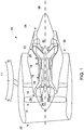
- FIG. 1 is a schematic diagram of an exemplary turbine engine 10 coupled to an airframe 11.
- Turbine engine 10 includes a fan assembly 12, a low-pressure or booster compressor assembly 14, a high-pressure compressor assembly 16, and a combustor assembly 18.
- Fan assembly 12, booster compressor assembly 14, high-pressure compressor assembly 16, and combustor assembly 18 are coupled in flow communication.
- Turbine engine 10 also includes a high-pressure turbine assembly 20 coupled in flow communication with combustor assembly 18 and a low-pressure turbine assembly 22.
- Fan assembly 12 includes an array of fan blades 24 extending radially outward from a rotor disk 26.
- Low-pressure turbine assembly 22 is coupled to fan assembly 12 and booster compressor assembly 14 through a first drive shaft 28, and high-pressure turbine assembly 20 is coupled to high-pressure compressor assembly 16 through a second drive shaft 30.
- Turbine engine 10 has an inlet 32 and a core exhaust 34.
- Turbine engine 10 further includes a centerline 36 about which fan assembly 12, booster compressor assembly 14, high-pressure compressor assembly 16, and turbine assemblies 20 and 22 rotate.
- FIG. 2 is a box diagram illustrating an exemplary turbine engine 10 and system 100 that may be used to deliver a payload within turbine engine 10.
- turbine engine 10 further includes an outer case 102 having an access point 104 defined therein.
- turbine engine 10 may be at least partially disassembled while coupled to airframe 11 (shown in FIG. 1 ) to define access point 104.
- Example access points may include, but are not limited to, borescope ports, ignitor ports, and the like.
- Access point 104 provides access to a confined space 106 and to an attachment point 108 within turbine engine 10.
- Confined space 106 is defined by components of turbine engine 10, as will be described in more detail below, and includes a maintenance location 110 in which an operation is to be performed.
- System 100 is positionable within confined space 106 to facilitate performing the maintenance operation at maintenance location 110.
- system 100 may be routed from exterior of outer case 102, through access point 104, and through turbine engine 10 to be positioned within confined space 106.
- system 100 is coupleable to attachment point 108 to facilitate positioning and stabilizing system 100 within turbine engine 10, and for enabling performance of the operation by system 100 within confined space 106.
- attachment point 108 is defined by blades 112 within turbine engine 10.
- system 100 couples to attachment point 108 by being mounted directly to one of blades 112, or by wedging itself between adjacent blades 112, for example.
- FIG. 3 is a perspective illustration of system 100.
- system 100 includes a guide tube 114, a tubular assembly 116, and a payload 118 coupled to tubular assembly 116.
- Guide tube 114 has a first portion 120, a second portion 122 having an open end 124, and an interior 126 extending through first portion 120 and second portion 122.
- First portion 120 and second portion 122 are oriented obliquely or perpendicularly relative to each other to enable guide tube 114 to be selectively oriented in multiple directions when being routed through turbine engine 10.
- Tubular assembly 116 is sized for insertion within, for deployment from, interior 126 of guide tube 114. For example, as shown in FIG. 3 , tubular assembly 116 is deployed from guide tube 114 for extension from open end 124.
- tubular assembly 116 is partially or fully retractable within interior 126 of guide tube 114.
- system 100 and more specifically tubular assembly 116, is positionable within confined space 106 (shown in FIG. 2 ) to facilitate positioning payload 118 proximate maintenance location 110 (shown in FIG. 2 ).
- tubular assembly 116 is routed through turbine engine 10 towards confined space 106 while at least partially retracted within guide tube 114.
- tubular assembly 116 is routable through turbine engine 10 in a controlled and predictable manner.
- guide tube 114 is a rigid structure having a predetermined shape, whereas tubular assembly 116 has a naturally bent shape when deployed from guide tube 114.
- guide tube 114 has a diameter of less than about 1 inch, which enables guide tube 114 to be routable through tight spaces within turbine engine 10.
- Tubular assembly 116 includes a first tubular body 128 and a second tubular body 130.
- First tubular body 128 has an interior channel 132
- second tubular body 130 is translatable and rotatable within interior channel 132.
- First tubular body 128 and second tubular body 130 are fabricated from a flexible material such as, but not limited to, a superelastic material such as nitinol, or a polymeric material.
- first tubular body 128 and second tubular body 130 are bendable between a neutral shape and a biased shape. The biased shape is formed when a biasing force is applied to first tubular body 128 and/or second tubular body 130, and the neutral shape is formed when the biasing force is removed therefrom.
- first tubular body 128 includes a first section 134, a second section 136, and a first bend 138 defined therebetween such that first section 134 and second section 136 are oriented obliquely or perpendicularly relative to each other when in the neutral shape.
- Second tubular body 130 includes a first section 140, a second section 142, and a second bend 144 defined therebetween such that first section 140 and second section 142 are oriented obliquely or perpendicularly relative to each other when in the neutral shape.
- Second tubular body 130 includes a tip end 146, and payload 118 is coupled to tip end 146.
- Payload 118 is any device, mechanism, or object that enables system 100 to maintain turbine engine 10, such as at maintenance location 110.
- Example payloads include, but are not limited to, a sensor, such as an eddy current sensor, a repair tool, a dispense tool (e.g., a spray or paste dispenser), and the like.
- system 100 also includes a camera 148 coupled to tip end 146. Camera 148 is operable to provide real-time visual feedback to an operator, for example, to facilitate routing tubular assembly system 100 through turbine engine 10, and to facilitate positioning payload 118 proximate maintenance location 110.
- Anchoring mechanism 150 is any device that enables tubular assembly 116 to be coupled to attachment point 108 within turbine engine 10 (both shown in FIG. 2 ).
- anchoring mechanism 150 may couple tubular assembly 116 to attachment point 108 with a physical attachment, such as a clamp, or with a suction attachment.
- anchoring mechanism 150 is an inflatable membrane 152 that selectively receives fluid, such as air, therein. Inflatable membrane 152 is deflated when tubular assembly 116 is retracted within guide tube 114, and is selectively inflatable when tubular assembly 116 is deployed from guide tube 114. When inflated, inflatable membrane 152 is sized to wedge itself between adjacent blades 112 (shown in FIG. 2 ), defining attachment point 108 to facilitate stabilizing tubular assembly 116 within confined space 106 (shown in FIG. 2 ).
- first tubular body 128 and second tubular body 130 are rotatable to selectively orient tip end 146 in multiple degrees of freedom.
- first tubular body 128 is rotatable relative to a first rotational axis 154
- second tubular body 130 is rotatable relative to a second rotational axis 156.
- First rotational axis 154 and second rotational axis 156 are oriented obliquely or perpendicularly relative to each other.
- second tubular body 130 is dependently rotatable with first tubular body 128, and is independently rotatable relative to first tubular body 128. As such, the orientation of tip end 146 is selected based on the rotation of first tubular body 128 and second tubular body 130.
- FIG. 4 is an enlarged view of a portion of system 100 (shown in FIG. 2 ), the portion being in a first operational position
- FIG. 5 is an enlarged view of the portion being in a second operational position
- system 100 includes a steering cable 158 extending from tip end 146 of second tubular body 130.
- Steering cable 158 may be used to bias tip end 146 for selective orientation in additional degrees of freedom.
- steering cable 158 is pullable in a pulling direction to provide a biasing force 160 to tip end 146.
- the biasing force facilitates further bending second tubular body 130 relative to the neutral shape (shown in FIG. 4 ).
- system 100 may include more than one steering cable 158, connected at the same or different longitudinal locations of second tubular body 130, to bias tip end 146.
- second tubular body 130 includes a plurality of slots 162.
- the plurality of slots 162 are positioned in a location along second tubular body 130 that facilitates the selective orientation of tip end 146 in the additional degrees of freedom. Slots 162 facilitate decreasing the stiffness of select regions of second tubular body 130 to enable second tubular body 130 to be elastically bendable upon application of tensile biasing force 160 via steering cable 158. Thus, slots 162 are positioned proximate tip end 146 to facilitate selectively orientating tip end 146 by pulling steering cable 158 with varying force.
- FIG. 6 is a schematic illustration of a portion of system 100 (shown in FIG. 2 ), the portion being in a first operational mode
- FIG. 7 is a schematic illustration of the portion being in a second operational mode.
- first tubular body 128 includes a first longitudinal section 164 and a second longitudinal section 166
- second tubular body 130 includes a first longitudinal section 168 and a second longitudinal section 170.
- First longitudinal sections 164 and 168 are selectively detachable from second longitudinal sections 166 and 170.
- an attachment mechanism 172 is coupled between first longitudinal section 164 and second longitudinal section 166. Attachment mechanism 172 may be any mechanism that enables system 100 to function as described herein.
- attachment mechanism 172 is capable of holding first longitudinal section 164 and second longitudinal section 166 together with a retaining force, releasing first longitudinal section 164 from second longitudinal section 166 when a force greater than the retaining force is applied, and then enabling re-attachment of first longitudinal section 164 and second longitudinal section 166 at a later time.
- Example attachment mechanisms 172 include, but are not limited to, a magnet and cables.
- attachment mechanism 172 includes a first magnet pair 174 coupled between first longitudinal section 164 and second longitudinal section 166, and a second magnet pair 176 coupled between first longitudinal section 168 and second longitudinal section 170.
- FIG. 8 is a schematic illustration of a portion of the turbine engine 10 having system 100 positioned therein.
- turbine engine 10 is partially disassembled to provide access to confined space 106 within turbine engine 10.
- confined space 106 is at least partially defined by components of turbine engine 10, and may include maintenance location 110 in which an operation is to be performed.
- System 100 is positioned within confined space 106 to facilitate performing an operation at maintenance location 110.
- system 100 is routed from access point 104 and through turbine engine 10 for positioning within confined space 106.
- Anchoring mechanism 150 is used to couple tubular assembly 116 to attachment point 108.
- the orientation of tubular assembly 116 may then be selectively modified, as described above, to facilitate positioning payload 118 (shown in FIG. 3 ) proximate maintenance location 110.
- Payload 118 may then perform an operation at maintenance location 110.
- payload 118 may be used to detect potential damage to components at maintenance location 110.
- anchoring mechanism 150 facilitates coupling tubular assembly 116 to blades 112 of turbine engine 10, and tubular assembly 116 is oriented to extend in a substantially radial direction relative to centerline 36 to reach maintenance location 110.
- tubular assembly 116 is orientatable in any direction relative to centerline 36.
- tubular assembly 116 is anchored on a rotor of turbine engine 10, and the rotor is turned to circumferentially position tubular assembly 116 proximate to maintenance location 110, positioned at a different circumferential location relative to centerline 36.
- second longitudinal sections 166 and 170 detach from first longitudinal sections 164 and 168, and travel with the rotating stage as it is rotated.
- system 100 may be used to deliver payload 118 and/or perform maintenance within turbine engine 10 without having to remove and then re-route system 100 through turbine engine 10.
- An exemplary technical effect of the systems and methods described herein includes at least one of: (a) enabling in-situ delivery of a maintenance payload within a turbine engine; (b) increasing the accessibility of difficult-to-reach locations within a turbine assembly for inspection and/or in-situ repair; (c) reducing the time that turbine engines are out of service for maintenance; and (d) reducing unplanned service outages for a turbine engine.
- Exemplary embodiments of methods and systems for use in delivering a maintenance payload within turbine engines are not limited to the specific embodiments described herein, but rather, components of systems and/or steps of the methods may be utilized independently and separately from other components and/or steps described herein.
- the methods and systems may also be used in combination with other systems requiring inspection and/or repair of components, and are not limited to practice with only the systems and methods as described herein.
- the exemplary embodiment can be implemented and utilized in connection with many other applications, equipment, and systems that may benefit from using a service apparatus for inspection and/or repair.
Landscapes
- Engineering & Computer Science (AREA)
- Physics & Mathematics (AREA)
- Mechanical Engineering (AREA)
- General Engineering & Computer Science (AREA)
- General Physics & Mathematics (AREA)
- Multimedia (AREA)
- Astronomy & Astrophysics (AREA)
- Optics & Photonics (AREA)
- Chemical & Material Sciences (AREA)
- Combustion & Propulsion (AREA)
- Structures Of Non-Positive Displacement Pumps (AREA)
Abstract
Description
- The field of the disclosure relates generally to turbomachine maintenance and, more particularly, to systems and a method for use in performing maintenance within a confined space of a turbomachine.
- At least some known turbine engines include an outer case and at least one rotor that includes multiple stages of rotating airfoils, i.e., blades, which rotate with respect to the outer case. In addition, the outer case includes multiple stages of stationary airfoils, i.e., guide vanes. The blades and guide vanes are arranged in alternating stages. In at least some known rotary machines, shrouds are disposed on the radially inner surfaces of a stator to form a ring seal around tips of the blades. Together, the blades, guide vanes, and shrouds define a primary flowpath inside the compressor and turbine sections of the rotary machine. This flowpath, combined with a flowpath through the combustor, defines a primary cavity within the turbine engine.
- During operation, the components of the turbine engine experience at least some material degradation as a function of the components' service history. Accordingly, for at least some known turbine engines, periodic inspections, such as borescope inspections, are performed to assess the condition of the turbine engine between service intervals. However, it may be difficult to inspect certain regions within the turbine engine with conventional borescope inspection techniques. As an alternative to conducting borescope inspections, at least some known turbine engines are at least partially disassembled from an airframe and moved to a facility to allow repair and/or replacement of damaged components at regularly scheduled service intervals. For example, damaged components the turbine engines are primarily repaired at overhaul or component repair facilities that are offsite from a location of the airframe. However, disassembling turbine engines for regular service and inspection is a costly and time-consuming endeavor.
- In one aspect, a system for use in servicing a turbomachine is provided. The system includes a first tubular body including an interior channel. The first tubular body is bendable between a neutral shape or a biased shape, with the first tubular body being bent when in the neutral shape. A second tubular body includes a tip end, wherein the second tubular body is translatable within the interior channel. The second tubular body is bendable between a neutral shape and a biased shape, with the second tubular body being bent when in the neutral shape. The first tubular body and the second tubular body are rotatable to selectively orient the tip end in multiple degrees of freedom. The system also includes a steering cable extending from the tip end, wherein the steering cable is configured to bias the tip end for selective orientation in additional degrees of freedom.
- In another aspect, a system for use in servicing a turbomachine is provided. The system includes a guide tube including an interior, and a tubular assembly sized for insertion within, and deployable from, the interior of the guide tube. The tubular assembly includes a first tubular body including an interior channel, and the first tubular body is bendable between a neutral shape or a biased shape, with the first tubular body being bent when in the neutral shape. A second tubular body of the tubular assembly includes a tip end. The second tubular body is translatable within the interior channel, and is bendable between a neutral shape and a biased shape, with the second tubular body being bent when in the neutral shape. The first tubular body and the second tubular body are rotatable to selectively orient the tip end in multiple degrees of freedom. The system also includes a steering cable extending from the tip end, wherein the steering cable is configured to bias the tip end for selective orientation in additional degrees of freedom, and a payload coupled to the tip end.
- In yet another aspect, a method of servicing a turbomachine is provided. The method includes disassembling the turbomachine to provide access to a confined space within the turbomachine, wherein the confined space includes a maintenance location. The method also includes positioning a tubular assembly within the confined space, the tubular assembly including a first tubular body having an interior channel, and the first tubular body being bent when in a neutral shape. A second tubular body of the tubular assembly has a tip end, wherein the second tubular body is translatable within the interior channel, and the second tubular body being bent when in a neutral shape. A payload is coupled to the tip end. The method also includes rotating at least one of the first tubular body and the second tubular body to selectively orient the tip end in multiple degrees of freedom to position the payload proximate the maintenance location, biasing, with a steering cable, the tip end for selective orientation in additional degrees of freedom to position the payload proximate the maintenance location, and performing an operation at the maintenance location with the payload.
- These and other features, aspects, and advantages of the present disclosure will become better understood when the following detailed description is read with reference to the accompanying drawings in which like characters represent like parts throughout the drawings, wherein:
-
FIG. 1 is a schematic illustration of an exemplary turbomachine; -
FIG. 2 is a box diagram illustrating an exemplary turbomachine and system that may be used to deliver a payload within the turbomachine; -
FIG. 3 is a perspective illustration of the system shown inFIG. 2 ; -
FIG. 4 is an enlarged view of a portion of the system shown inFIG. 2 , the portion being in a first operational position; -
FIG. 5 is an enlarged view of the portion of the system shown inFIG. 4 , the portion being in a second operational position; -
FIG. 6 is a schematic illustration of a portion of the system shown inFIG. 2 , the portion being in a first operational mode; -
FIG. 7 is a schematic illustration of the portion of the system shown inFIG. 6 , the portion being in a second operational mode; and -
FIG. 8 is a schematic illustration of a portion of the turbomachine shown inFIG. 1 having the system shown inFIG. 3 positioned therein. - Unless otherwise indicated, the drawings provided herein are meant to illustrate features of embodiments of this disclosure. These features are believed to be applicable in a wide variety of systems comprising one or more embodiments of this disclosure. As such, the drawings are not meant to include all conventional features known by those of ordinary skill in the art to be required for the practice of the embodiments disclosed herein.
- In the following specification and the claims, reference will be made to a number of terms, which shall be defined to have the following meanings.
- The singular forms "a", "an", and "the" include plural references unless the context clearly dictates otherwise.
- "Optional" or "optionally" means that the subsequently described event or circumstance may or may not occur, and that the description includes instances where the event occurs and instances where it does not.
- Approximating language, as used herein throughout the specification and claims, may be applied to modify any quantitative representation that could permissibly vary without resulting in a change in the basic function to which it is related. Accordingly, a value modified by a term or terms, such as "about", "approximately", and "substantially", are not to be limited to the precise value specified. In at least some instances, the approximating language may correspond to the precision of an instrument for measuring the value. Here and throughout the specification and claims, range limitations may be combined and/or interchanged, such ranges are identified and include all the sub-ranges contained therein unless context or language indicates otherwise.
- Embodiments of the present disclosure relate to systems and a method for use in performing maintenance within a confined space of a turbomachine, such as a turbine engine. In the exemplary embodiment, the systems described herein include a tubular assembly including a first tubular body and a second tubular body. The second tubular body is sized for insertion within the first tubular body. The first tubular body is rotatable relative to its longitudinal axis when positioned within the confined space, and the second tubular body is rotatable and translatable relative to the first tubular body. In addition, the first and second tubular bodies are each bendable between a neutral shape and a biased shape. The bodies are bent when in the neutral shape, such that a tip end of the second tubular body is selectively orientable in multiple degrees of freedom by rotating one or both of the first and second tubular bodies. A steering cable extending from the tip end may also be used to bias the tip end for selective orientation in additional degrees of freedom. A payload may be coupled to the tip end. As such, the tubular assembly enables the payload to be maneuvered around obstacles within the turbine engine for positioning the payload proximate a maintenance location. The payload may then perform an operation at the maintenance location such as, but not limited to, an inspection operation. As such, the systems and method described herein enable in-situ inspection of turbine engine components that are positioned in confined or hard-to-reach locations.
-
FIG. 1 is a schematic diagram of anexemplary turbine engine 10 coupled to anairframe 11.Turbine engine 10 includes afan assembly 12, a low-pressure orbooster compressor assembly 14, a high-pressure compressor assembly 16, and acombustor assembly 18.Fan assembly 12,booster compressor assembly 14, high-pressure compressor assembly 16, andcombustor assembly 18 are coupled in flow communication.Turbine engine 10 also includes a high-pressure turbine assembly 20 coupled in flow communication withcombustor assembly 18 and a low-pressure turbine assembly 22.Fan assembly 12 includes an array offan blades 24 extending radially outward from arotor disk 26. Low-pressure turbine assembly 22 is coupled tofan assembly 12 andbooster compressor assembly 14 through afirst drive shaft 28, and high-pressure turbine assembly 20 is coupled to high-pressure compressor assembly 16 through asecond drive shaft 30.Turbine engine 10 has aninlet 32 and acore exhaust 34.Turbine engine 10 further includes acenterline 36 about whichfan assembly 12,booster compressor assembly 14, high-pressure compressor assembly 16, andturbine assemblies 20 and 22 rotate. - In operation, some of the air entering
turbine engine 10 throughinlet 32 is channeled throughfan assembly 12 towardsbooster compressor assembly 14. Compressed air is discharged frombooster compressor assembly 14 towards high-pressure compressor assembly 16. Highly compressed air is channeled from high-pressure compressor assembly 16 towardscombustor assembly 18, mixed with fuel, and the mixture is combusted withincombustor assembly 18. High temperature combustion gas generated bycombustor assembly 18 is channeled throughturbine assemblies 20 and 22. Combustion gas is subsequently discharged fromturbine engine 10 viacore exhaust 34 and afan exhaust 38. -
FIG. 2 is a box diagram illustrating anexemplary turbine engine 10 andsystem 100 that may be used to deliver a payload withinturbine engine 10. In the exemplary embodiment,turbine engine 10 further includes anouter case 102 having anaccess point 104 defined therein. For example,turbine engine 10 may be at least partially disassembled while coupled to airframe 11 (shown inFIG. 1 ) to defineaccess point 104. Example access points may include, but are not limited to, borescope ports, ignitor ports, and the like.Access point 104 provides access to a confinedspace 106 and to anattachment point 108 withinturbine engine 10. Confinedspace 106 is defined by components ofturbine engine 10, as will be described in more detail below, and includes amaintenance location 110 in which an operation is to be performed. -
System 100 is positionable within confinedspace 106 to facilitate performing the maintenance operation atmaintenance location 110. For example,system 100 may be routed from exterior ofouter case 102, throughaccess point 104, and throughturbine engine 10 to be positioned within confinedspace 106. In some embodiments,system 100 is coupleable toattachment point 108 to facilitate positioning and stabilizingsystem 100 withinturbine engine 10, and for enabling performance of the operation bysystem 100 within confinedspace 106. In the exemplary embodiment,attachment point 108 is defined byblades 112 withinturbine engine 10. As will be described in more detail below,system 100 couples toattachment point 108 by being mounted directly to one ofblades 112, or by wedging itself betweenadjacent blades 112, for example. -
FIG. 3 is a perspective illustration ofsystem 100. In the exemplary embodiment,system 100 includes aguide tube 114, atubular assembly 116, and apayload 118 coupled totubular assembly 116.Guide tube 114 has afirst portion 120, asecond portion 122 having anopen end 124, and an interior 126 extending throughfirst portion 120 andsecond portion 122.First portion 120 andsecond portion 122 are oriented obliquely or perpendicularly relative to each other to enableguide tube 114 to be selectively oriented in multiple directions when being routed throughturbine engine 10.Tubular assembly 116 is sized for insertion within, for deployment from,interior 126 ofguide tube 114. For example, as shown inFIG. 3 ,tubular assembly 116 is deployed fromguide tube 114 for extension fromopen end 124. - Alternatively,
tubular assembly 116 is partially or fully retractable withininterior 126 ofguide tube 114. As noted above,system 100, and more specificallytubular assembly 116, is positionable within confined space 106 (shown inFIG. 2 ) to facilitatepositioning payload 118 proximate maintenance location 110 (shown inFIG. 2 ). In operation,tubular assembly 116 is routed throughturbine engine 10 towards confinedspace 106 while at least partially retracted withinguide tube 114. As such,tubular assembly 116 is routable throughturbine engine 10 in a controlled and predictable manner. For example, guidetube 114 is a rigid structure having a predetermined shape, whereastubular assembly 116 has a naturally bent shape when deployed fromguide tube 114. In addition, in one embodiment, guidetube 114 has a diameter of less than about 1 inch, which enablesguide tube 114 to be routable through tight spaces withinturbine engine 10. -
Tubular assembly 116 includes a firsttubular body 128 and a secondtubular body 130. Firsttubular body 128 has aninterior channel 132, and secondtubular body 130 is translatable and rotatable withininterior channel 132. Firsttubular body 128 and secondtubular body 130 are fabricated from a flexible material such as, but not limited to, a superelastic material such as nitinol, or a polymeric material. As such, firsttubular body 128 and secondtubular body 130 are bendable between a neutral shape and a biased shape. The biased shape is formed when a biasing force is applied to firsttubular body 128 and/or secondtubular body 130, and the neutral shape is formed when the biasing force is removed therefrom. In one embodiment, the biasing force is applied bysecond portion 122 ofguide tube 114 when firsttubular body 128 and secondtubular body 130 are retracted therein. The neutral shape is formed when firsttubular body 128 is deployed fromguide tube 114 by a predetermined distance, and when secondtubular body 130 is deployed from firsttubular body 128 by a predetermined distance. For example, firsttubular body 128 includes afirst section 134, asecond section 136, and afirst bend 138 defined therebetween such thatfirst section 134 andsecond section 136 are oriented obliquely or perpendicularly relative to each other when in the neutral shape. Secondtubular body 130 includes afirst section 140, asecond section 142, and asecond bend 144 defined therebetween such thatfirst section 140 andsecond section 142 are oriented obliquely or perpendicularly relative to each other when in the neutral shape. - Second
tubular body 130 includes atip end 146, andpayload 118 is coupled to tipend 146.Payload 118 is any device, mechanism, or object that enablessystem 100 to maintainturbine engine 10, such as atmaintenance location 110. Example payloads include, but are not limited to, a sensor, such as an eddy current sensor, a repair tool, a dispense tool (e.g., a spray or paste dispenser), and the like. In the exemplary embodiment,system 100 also includes acamera 148 coupled to tipend 146.Camera 148 is operable to provide real-time visual feedback to an operator, for example, to facilitate routingtubular assembly system 100 throughturbine engine 10, and to facilitatepositioning payload 118proximate maintenance location 110. -
System 100 also includes ananchoring mechanism 150 coupled totubular assembly 116.Anchoring mechanism 150 is any device that enablestubular assembly 116 to be coupled toattachment point 108 within turbine engine 10 (both shown inFIG. 2 ). For example,anchoring mechanism 150 may coupletubular assembly 116 toattachment point 108 with a physical attachment, such as a clamp, or with a suction attachment. In the exemplary embodiment,anchoring mechanism 150 is aninflatable membrane 152 that selectively receives fluid, such as air, therein.Inflatable membrane 152 is deflated whentubular assembly 116 is retracted withinguide tube 114, and is selectively inflatable whentubular assembly 116 is deployed fromguide tube 114. When inflated,inflatable membrane 152 is sized to wedge itself between adjacent blades 112 (shown inFIG. 2 ), definingattachment point 108 to facilitate stabilizingtubular assembly 116 within confined space 106 (shown inFIG. 2 ). - In operation, first
tubular body 128 and secondtubular body 130 are rotatable to selectively orienttip end 146 in multiple degrees of freedom. For example, when deployed, firsttubular body 128 is rotatable relative to a firstrotational axis 154, and secondtubular body 130 is rotatable relative to a secondrotational axis 156. Firstrotational axis 154 and secondrotational axis 156 are oriented obliquely or perpendicularly relative to each other. In addition, in one embodiment, secondtubular body 130 is dependently rotatable with firsttubular body 128, and is independently rotatable relative to firsttubular body 128. As such, the orientation oftip end 146 is selected based on the rotation of firsttubular body 128 and secondtubular body 130. -
FIG. 4 is an enlarged view of a portion of system 100 (shown inFIG. 2 ), the portion being in a first operational position, andFIG. 5 is an enlarged view of the portion being in a second operational position. In the exemplary embodiment,system 100 includes asteering cable 158 extending fromtip end 146 of secondtubular body 130.Steering cable 158 may be used to biastip end 146 for selective orientation in additional degrees of freedom. For example, in operation, steeringcable 158 is pullable in a pulling direction to provide a biasingforce 160 to tipend 146. The biasing force facilitates further bending secondtubular body 130 relative to the neutral shape (shown inFIG. 4 ). In some embodiments,system 100 may include more than onesteering cable 158, connected at the same or different longitudinal locations of secondtubular body 130, to biastip end 146. - In the exemplary embodiment, second
tubular body 130 includes a plurality ofslots 162. The plurality ofslots 162 are positioned in a location along secondtubular body 130 that facilitates the selective orientation oftip end 146 in the additional degrees of freedom.Slots 162 facilitate decreasing the stiffness of select regions of secondtubular body 130 to enable secondtubular body 130 to be elastically bendable upon application oftensile biasing force 160 viasteering cable 158. Thus,slots 162 are positionedproximate tip end 146 to facilitate selectively orientatingtip end 146 by pullingsteering cable 158 with varying force. -
FIG. 6 is a schematic illustration of a portion of system 100 (shown inFIG. 2 ), the portion being in a first operational mode, andFIG. 7 is a schematic illustration of the portion being in a second operational mode. In the exemplary embodiment, firsttubular body 128 includes a firstlongitudinal section 164 and a secondlongitudinal section 166, and secondtubular body 130 includes a firstlongitudinal section 168 and a secondlongitudinal section 170. Firstlongitudinal sections longitudinal sections attachment mechanism 172 is coupled between firstlongitudinal section 164 and secondlongitudinal section 166.Attachment mechanism 172 may be any mechanism that enablessystem 100 to function as described herein. For example,attachment mechanism 172 is capable of holding firstlongitudinal section 164 and secondlongitudinal section 166 together with a retaining force, releasing firstlongitudinal section 164 from secondlongitudinal section 166 when a force greater than the retaining force is applied, and then enabling re-attachment of firstlongitudinal section 164 and secondlongitudinal section 166 at a later time.Example attachment mechanisms 172 include, but are not limited to, a magnet and cables. In one embodiment,attachment mechanism 172 includes afirst magnet pair 174 coupled between firstlongitudinal section 164 and secondlongitudinal section 166, and asecond magnet pair 176 coupled between firstlongitudinal section 168 and secondlongitudinal section 170. -
FIG. 8 is a schematic illustration of a portion of theturbine engine 10 havingsystem 100 positioned therein. In the exemplary embodiment,turbine engine 10 is partially disassembled to provide access to confinedspace 106 withinturbine engine 10. As described above, confinedspace 106 is at least partially defined by components ofturbine engine 10, and may includemaintenance location 110 in which an operation is to be performed.System 100 is positioned within confinedspace 106 to facilitate performing an operation atmaintenance location 110. For example,system 100 is routed fromaccess point 104 and throughturbine engine 10 for positioning within confinedspace 106.Anchoring mechanism 150 is used to coupletubular assembly 116 toattachment point 108. The orientation oftubular assembly 116 may then be selectively modified, as described above, to facilitate positioning payload 118 (shown inFIG. 3 )proximate maintenance location 110.Payload 118 may then perform an operation atmaintenance location 110. For example, whenpayload 118 is a sensor,payload 118 may be used to detect potential damage to components atmaintenance location 110. - In the exemplary embodiment,
anchoring mechanism 150 facilitates couplingtubular assembly 116 toblades 112 ofturbine engine 10, andtubular assembly 116 is oriented to extend in a substantially radial direction relative to centerline 36 to reachmaintenance location 110. However,tubular assembly 116 is orientatable in any direction relative tocenterline 36. In one embodiment,tubular assembly 116 is anchored on a rotor ofturbine engine 10, and the rotor is turned to circumferentially positiontubular assembly 116 proximate tomaintenance location 110, positioned at a different circumferential location relative tocenterline 36. In such an embodiment, secondlongitudinal sections longitudinal sections system 100 may be used to deliverpayload 118 and/or perform maintenance withinturbine engine 10 without having to remove and then re-routesystem 100 throughturbine engine 10. - An exemplary technical effect of the systems and methods described herein includes at least one of: (a) enabling in-situ delivery of a maintenance payload within a turbine engine; (b) increasing the accessibility of difficult-to-reach locations within a turbine assembly for inspection and/or in-situ repair; (c) reducing the time that turbine engines are out of service for maintenance; and (d) reducing unplanned service outages for a turbine engine.
- Exemplary embodiments of methods and systems for use in delivering a maintenance payload within turbine engines are not limited to the specific embodiments described herein, but rather, components of systems and/or steps of the methods may be utilized independently and separately from other components and/or steps described herein. For example, the methods and systems may also be used in combination with other systems requiring inspection and/or repair of components, and are not limited to practice with only the systems and methods as described herein. Rather, the exemplary embodiment can be implemented and utilized in connection with many other applications, equipment, and systems that may benefit from using a service apparatus for inspection and/or repair.
- Although specific features of various embodiments of the disclosure may be shown in some drawings and not in others, this is for convenience only. In accordance with the principles of the disclosure, any feature of a drawing may be referenced and/or claimed in combination with any feature of any other drawing.
- This written description uses examples to disclose the embodiments, including the best mode, and also to enable any person skilled in the art to practice the embodiments, including making and using any devices or systems and performing any incorporated methods. The patentable scope of the disclosure is defined by the claims, and may include other examples that occur to those skilled in the art. Such other examples are intended to be within the scope of the claims if they have structural elements that do not differ from the literal language of the claims, or if they include equivalent structural elements with insubstantial differences from the literal language of the claims.
- Further aspects of the invention are provided by the subject matter of the following clauses:
- 1. A system for use in servicing a turbomachine, the system comprising:
- a first tubular body comprising an interior channel, wherein the first tubular body is bendable between a neutral shape or a biased shape, the first tubular body being bent when in the neutral shape;
- a second tubular body comprising a tip end, wherein the second tubular body is translatable within the interior channel, and is bendable between a neutral shape and a biased shape, the second tubular body being bent when in the neutral shape, wherein the first tubular body and the second tubular body are rotatable to selectively orient the tip end in multiple degrees of freedom; and
- a steering cable extending from the tip end, wherein the steering cable is configured to bias the tip end for selective orientation in additional degrees of freedom.
- 2. The system in accordance with any preceding clause, wherein the second tubular body is dependently rotatable with the first tubular body, and is independently rotatable relative to the first tubular body.
- 3. The system in accordance with any preceding clause, wherein the second tubular body further comprises a plurality of slots defined therein, the plurality of slots positioned in a location along the second tubular body that facilitates the selective orientation of the tip end in the additional degrees of freedom.
- 4. The system in accordance with any preceding clause, wherein the first tubular body and the second tubular body each comprise a first longitudinal section and a second longitudinal section that are selectively detachable from each other.
- 5. The system in accordance with any preceding clause further comprising an anchoring mechanism configured to couple the first tubular body to an attachment point within the turbomachine.
- 6. The system in accordance with any preceding clause further comprising a camera coupled to the tip end of the second tubular body.
- 7. The system in accordance with any preceding clause, wherein at least one of the first tubular body and the second tubular body are fabricated from a superelastic material.
- 8. A system for use in servicing a turbomachine, the system comprising:
- a guide tube comprising an interior;
- a tubular assembly sized for insertion within, and deployable from, the interior of the guide tube, the tubular assembly comprising:
- a first tubular body comprising an interior channel, wherein the first tubular body is bendable between a neutral shape or a biased shape, the first tubular body being bent when in the neutral shape; and
- a second tubular body comprising a tip end, wherein the second tubular body is translatable within the interior channel, and is bendable between a neutral shape and a biased shape, the second tubular body being bent when in the neutral shape, wherein the first tubular body and the second tubular body are rotatable to selectively orient the tip end in multiple degrees of freedom;
- a steering cable extending from the tip end, wherein the steering cable is configured to bias the tip end for selective orientation in additional degrees of freedom; and
- a payload coupled to the tip end.
- 9. The system in accordance with any preceding clause, wherein the guide tube has a diameter of less than about 1 inch.
- 10. The system in accordance with any preceding clause, wherein the second tubular body is dependently rotatable with the first tubular body, and is independently rotatable relative to the first tubular body.
- 11. The system in accordance with any preceding clause, wherein the second tubular body further comprises a plurality of slots defined therein, the plurality of slots positioned in a location along the second tubular body that facilitates the selective orientation of the tip end in the additional degrees of freedom.
- 12. The system in accordance with any preceding clause, wherein the first tubular body and the second tubular body each comprise a first longitudinal section and a second longitudinal section that are selectively detachable from each other.
- 13. The system in accordance with any preceding clause further comprising an anchoring mechanism configured to couple the first tubular body and the second tubular body to an attachment point within the turbomachine.
- 14. The system in accordance with any preceding clause, wherein at least one of the first tubular body and the second tubular body are fabricated from a superelastic material.
- 15. A method of servicing a turbomachine, the method comprising:
- providing access to a confined space within the turbomachine, wherein the confined space includes a maintenance location;
- positioning a tubular assembly within the confined space, the tubular assembly including:
- a first tubular body having an interior channel, the first tubular body being bent when in a neutral shape; and
- a second tubular body having a tip end, wherein the second tubular body is translatable within the interior channel, the second tubular body being bent when in a neutral shape, wherein a payload is coupled to the tip end;
- rotating at least one of the first tubular body and the second tubular body to selectively orient the tip end in multiple degrees of freedom to position the payload proximate the maintenance location;
- biasing, with a steering cable, the tip end for selective orientation in additional degrees of freedom to position the payload proximate the maintenance location; and
- performing a maintenance operation at the maintenance location with the payload.
- 16. The method in accordance with any preceding clause, wherein rotating at least one of the first tubular body and the second tubular body comprises:
- selectively rotating the first tubular body, wherein the second tubular body is dependently rotatable with the first tubular body; and
- selectively rotating the second tubular body independently of the first tubular body.
- 17. The method in accordance with any preceding clause, wherein the first tubular body and the second tubular body each comprise a first longitudinal section and a second longitudinal section that are selectively detachable from each other, the method further comprising:
- positioning the tubular assembly within a rotating stage of the turbomachine;
- anchoring the first longitudinal section to an attachment point within the rotating stage; and
- rotating the rotating stage such that the first longitudinal section detaches from the second longitudinal section.
- 18. The method in accordance with any preceding clause, wherein providing access to a confined space comprises disassembling the machine.
- 19. The method in accordance with any preceding clause, wherein providing access to a confined space comprises defining an access point in an outer case of the turbomachine, the method further comprising routing the tubular assembly from the access point and through the turbomachine for positioning within the confined space.
- 20. The method in accordance with any preceding clause, wherein guiding the tubular assembly comprises:
routing a guide tube from the access point towards the confined space, wherein the guide tube contains the tubular assembly therein; and
deploying the tubular assembly from the guide tube into the confined space.
Claims (14)
- A system for use in servicing a turbomachine, the system comprising:a first tubular body (128) comprising an interior channel (132), wherein the first tubular body (128) is bendable between a neutral shape or a biased shape, the first tubular body (128) being bent when in the neutral shape;a second tubular body (130) comprising a tip end (146), wherein the second tubular body (130) is translatable within the interior channel (132), and is bendable between a neutral shape and a biased shape, the second tubular body (130) being bent when in the neutral shape, wherein the first tubular body (128) and the second tubular body (130) are rotatable to selectively orient the tip end (146) in multiple degrees of freedom; anda steering cable (158) extending from the tip end (146), wherein the steering cable (158) is configured to bias the tip end (146) for selective orientation in additional degrees of freedom.
- The system in accordance with Claim 1, wherein the second tubular body (130) is dependently rotatable with the first tubular body (128), and is independently rotatable relative to the first tubular body (128).
- The system in accordance with Claim 1 or 2, wherein the second tubular body (130) further comprises a plurality of slots (162) defined therein, the plurality of slots (162) positioned in a location along the second tubular body (130) that facilitates the selective orientation of the tip end (146) in the additional degrees of freedom.
- The system in accordance with any of Claims 1 to 3, wherein the first tubular body (128) and the second tubular body (130) each comprise a first longitudinal section (164) and a second longitudinal section (166) that are selectively detachable from each other.
- The system in accordance with any of Claims 1 to 4 further comprising an anchoring mechanism (150) configured to couple the first tubular body (128) to an attachment point (108) within the turbomachine.
- The system in accordance with any of Claims 1 to 5 further comprising a camera (148) coupled to the tip end (146) of the second tubular body (130).
- The system in accordance with any of Claims 1 to 6, wherein at least one of the first tubular body (128) and the second tubular body (130) are fabricated from a superelastic material.
- A system for use in servicing a turbomachine, the system comprising:a guide tube (114) comprising an interior (126);a tubular assembly (116) sized for insertion within, and deployable from, the interior (126) of the guide tube (114), the tubular assembly (116) comprising:a first tubular body (128) comprising an interior channel (132), wherein the first tubular body (128) is bendable between a neutral shape or a biased shape, the first tubular body (128) being bent when in the neutral shape; anda second tubular body (130) comprising a tip end (146), wherein the second tubular body (130) is translatable within the interior channel (132), and is bendable between a neutral shape and a biased shape, the second tubular body (130) being bent when in the neutral shape, wherein the first tubular body (128) and the second tubular body (130) are rotatable to selectively orient the tip end (146) in multiple degrees of freedom;a steering cable (158) extending from the tip end (146), wherein the steering cable (158) is configured to bias the tip end (146) for selective orientation in additional degrees of freedom; anda payload (118) coupled to the tip end (146).
- The system in accordance with Claim 8, wherein the guide tube (114) has a diameter of less than about 1 inch.
- The system in accordance with Claim 8 or 9, wherein the second tubular body (130) is dependently rotatable with the first tubular body (128), and is independently rotatable relative to the first tubular body (128).
- The system in accordance with any of Claims 8 to 10, wherein the second tubular body (130) further comprises a plurality of slots (162) defined therein, the plurality of slots (162) positioned in a location along the second tubular body (130) that facilitates the selective orientation of the tip end (146) in the additional degrees of freedom.
- The system in accordance with any of Claims 8 to 11, wherein the first tubular body (128) and the second tubular body (130) each comprise a first longitudinal section (164) and a second longitudinal section (166) that are selectively detachable from each other.
- The system in accordance with any of Claims 8 to 12 further comprising an anchoring mechanism (150) configured to couple the first tubular body (128) and the second tubular body (130) to an attachment point (108) within the turbomachine.
- The system in accordance with any of Claims 8 to 13, wherein at least one of the first tubular body (128) and the second tubular body (130) are fabricated from a superelastic material.
Applications Claiming Priority (1)
| Application Number | Priority Date | Filing Date | Title |
|---|---|---|---|
| US16/653,424 US11480068B2 (en) | 2019-10-15 | 2019-10-15 | Systems and method of servicing a turbomachine |
Publications (1)
| Publication Number | Publication Date |
|---|---|
| EP3808944A1 true EP3808944A1 (en) | 2021-04-21 |
Family
ID=72826779
Family Applications (1)
| Application Number | Title | Priority Date | Filing Date |
|---|---|---|---|
| EP20201115.1A Pending EP3808944A1 (en) | 2019-10-15 | 2020-10-09 | Maintenance system with tubular assembly for servicing a turbomachine |
Country Status (3)
| Country | Link |
|---|---|
| US (1) | US11480068B2 (en) |
| EP (1) | EP3808944A1 (en) |
| CN (1) | CN112664278B (en) |
Cited By (1)
| Publication number | Priority date | Publication date | Assignee | Title |
|---|---|---|---|---|
| EP4647762A1 (en) * | 2024-05-08 | 2025-11-12 | RTX Corporation | Inspecting internal powerplant component using inspection scope |
Families Citing this family (2)
| Publication number | Priority date | Publication date | Assignee | Title |
|---|---|---|---|---|
| DE102018209609A1 (en) * | 2018-06-14 | 2019-12-19 | MTU Aero Engines AG | Inspection procedure and system |
| EP4201603A1 (en) * | 2021-12-21 | 2023-06-28 | Rolls-Royce plc | Means for stiffening a continuum arm robot |
Citations (11)
| Publication number | Priority date | Publication date | Assignee | Title |
|---|---|---|---|---|
| FR2186213A1 (en) * | 1972-05-30 | 1974-01-11 | American Optical Corp | |
| US3841764A (en) * | 1969-12-09 | 1974-10-15 | Secr Defence | Intrascope |
| US4298312A (en) * | 1979-07-24 | 1981-11-03 | Purex Corporation | Damaged vane locating method and apparatus |
| US4659195A (en) * | 1986-01-31 | 1987-04-21 | American Hospital Supply Corporation | Engine inspection system |
| US5155941A (en) * | 1989-09-18 | 1992-10-20 | Olympus Optical Co., Ltd. | Industrial endoscope system having a rotary treatment member |
| DE10052679A1 (en) * | 1999-10-26 | 2001-05-31 | Circon Corp | Endoscope has control section and shaft with frame, and pipe containing slits |
| EP1811136A2 (en) * | 2006-01-24 | 2007-07-25 | Rolls-Royce plc | A method of securing a component in an engine |
| US20080064921A1 (en) * | 2006-06-13 | 2008-03-13 | Intuitive Surgical, Inc. | Guide tube control of minimally invasive surgical instruments |
| WO2011058008A1 (en) * | 2009-11-10 | 2011-05-19 | Siemens Aktiengesellschaft | Inspection device and method for positioning an inspection device |
| EP2623731A1 (en) * | 2012-02-06 | 2013-08-07 | Rolls-Royce Deutschland Ltd & Co KG | Device and process for the processing of high pressure turbine blade in a gas turbine |
| US20150088161A1 (en) * | 2013-09-20 | 2015-03-26 | Canon U.S.A., Inc. | Control apparatus and tendon-driven device |
Family Cites Families (37)
| Publication number | Priority date | Publication date | Assignee | Title |
|---|---|---|---|---|
| US7169141B2 (en) | 1998-02-24 | 2007-01-30 | Hansen Medical, Inc. | Surgical instrument |
| US20030135204A1 (en) | 2001-02-15 | 2003-07-17 | Endo Via Medical, Inc. | Robotically controlled medical instrument with a flexible section |
| US6817974B2 (en) | 2001-06-29 | 2004-11-16 | Intuitive Surgical, Inc. | Surgical tool having positively positionable tendon-actuated multi-disk wrist joint |
| US7591783B2 (en) | 2003-04-01 | 2009-09-22 | Boston Scientific Scimed, Inc. | Articulation joint for video endoscope |
| US6943570B2 (en) | 2003-09-26 | 2005-09-13 | Honeywell International, Inc. | Device for detecting a crack on a turbine blade of an aircraft engine |
| JP4980899B2 (en) | 2004-06-25 | 2012-07-18 | カーネギー メロン ユニバーシティ | Steerable follow-the-reader device |
| CA2630061C (en) | 2005-11-15 | 2015-03-17 | Johns Hopkins University | An active cannula for bio-sensing and surgical intervention |
| JP5722542B2 (en) | 2006-09-14 | 2015-05-20 | コーニンクレッカ フィリップス エヌ ヴェ | Active cannula system |
| US20110015490A1 (en) | 2008-03-20 | 2011-01-20 | Koninklijke Philips Electronics N.V. | Method and system for cannula positioning |
| GB0808432D0 (en) | 2008-05-12 | 2008-06-18 | Rolls Royce Plc | An inspection arrangement |
| EP2303157A1 (en) | 2008-06-25 | 2011-04-06 | Koninklijke Philips Electronics N.V. | Nested cannulae for minimally invasive surgery |
| CN102084382A (en) | 2008-06-26 | 2011-06-01 | 皇家飞利浦电子股份有限公司 | Method and system for fast precise path planning |
| US20110201887A1 (en) | 2008-10-17 | 2011-08-18 | Koninklijke Philips Electronics N.V. | Interlocking nested cannula |
| EP2381865A1 (en) | 2008-12-23 | 2011-11-02 | Koninklijke Philips Electronics N.V. | Nested cannula configuration for use with endoscope |
| WO2010076674A1 (en) | 2008-12-29 | 2010-07-08 | Koninklijke Philips Electronics, N.V. | Planning and assembly of compensating concentric cannulas |
| EP2381868A1 (en) | 2008-12-29 | 2011-11-02 | Koninklijke Philips Electronics B.V. | Planning for curvature interactions, multiple radii of curvature and adaptive neighborhoods |
| BRPI0918308A2 (en) | 2008-12-29 | 2020-08-04 | Koninklijke Philips Electronics N.V. | method for planning a route according to a surgical application, and system for planning a route according to a surgical application |
| US20120029288A1 (en) | 2009-03-31 | 2012-02-02 | Koninklijke Philips Electronics N.V. | Helical continuous curvature tubes for nested cannulas |
| WO2011057031A1 (en) | 2009-11-04 | 2011-05-12 | Triune Ip Llc | Remote manipulation apparatus and system |
| US10737398B2 (en) | 2010-07-08 | 2020-08-11 | Vanderbilt University | Continuum devices and control methods thereof |
| WO2013026012A1 (en) | 2011-08-18 | 2013-02-21 | President And Fellows Of Harvard College | Hybrid snake robot for minimally invasive intervention |
| WO2013074970A1 (en) | 2011-11-16 | 2013-05-23 | Vanderbilt University | Motive device for use in magnetically-sensitive environments |
| US9539726B2 (en) | 2012-04-20 | 2017-01-10 | Vanderbilt University | Systems and methods for safe compliant insertion and hybrid force/motion telemanipulation of continuum robots |
| US9333650B2 (en) | 2012-05-11 | 2016-05-10 | Vanderbilt University | Method and system for contact detection and contact localization along continuum robots |
| JP6084296B2 (en) | 2013-02-25 | 2017-02-22 | オリンパス株式会社 | Medical system |
| US9282993B1 (en) | 2013-03-15 | 2016-03-15 | Southern Methodist University | Steerable extendable devices |
| US10238457B2 (en) | 2013-09-13 | 2019-03-26 | Vanderbilt University | System and method for endoscopic deployment of robotic concentric tube manipulators for performing surgery |
| WO2015073943A1 (en) | 2013-11-18 | 2015-05-21 | Vanderbilt University | System and apparatus for performing transforminal therapy |
| US10548630B2 (en) | 2014-02-11 | 2020-02-04 | Vanderbilt University | System, method, and apparatus for configuration, design, and operation of an active cannula robot |
| US10434644B2 (en) | 2014-11-03 | 2019-10-08 | The Board Of Trustees Of The Leland Stanford Junior University | Position/force control of a flexible manipulator under model-less control |
| WO2016191364A1 (en) | 2015-05-22 | 2016-12-01 | The University Of North Carolina At Chapel Hill | Methods, systems, and computer readable media for controlling a concentric tube probe |
| US20160346513A1 (en) | 2015-05-26 | 2016-12-01 | Vanderbilt University | Surgical device tip with arc length varying curvature |
| US10441371B2 (en) | 2015-10-02 | 2019-10-15 | Vanderbilt University | Concentric tube robot |
| US10307214B2 (en) | 2015-11-23 | 2019-06-04 | Vanderbilt University | Modular sterilizable robotic system for endonasal surgery |
| US10912620B2 (en) | 2016-01-06 | 2021-02-09 | Vanderbilt University | Snare tool manipulator system |
| US10822950B2 (en) * | 2016-06-17 | 2020-11-03 | General Electric Company | System and method for performing an in situ repair of an internal component of a gas turbine engine |
| US10494926B2 (en) * | 2017-08-28 | 2019-12-03 | General Electric Company | System and method for maintaining machines |
-
2019
- 2019-10-15 US US16/653,424 patent/US11480068B2/en active Active
-
2020
- 2020-10-09 EP EP20201115.1A patent/EP3808944A1/en active Pending
- 2020-10-15 CN CN202011102817.1A patent/CN112664278B/en active Active
Patent Citations (11)
| Publication number | Priority date | Publication date | Assignee | Title |
|---|---|---|---|---|
| US3841764A (en) * | 1969-12-09 | 1974-10-15 | Secr Defence | Intrascope |
| FR2186213A1 (en) * | 1972-05-30 | 1974-01-11 | American Optical Corp | |
| US4298312A (en) * | 1979-07-24 | 1981-11-03 | Purex Corporation | Damaged vane locating method and apparatus |
| US4659195A (en) * | 1986-01-31 | 1987-04-21 | American Hospital Supply Corporation | Engine inspection system |
| US5155941A (en) * | 1989-09-18 | 1992-10-20 | Olympus Optical Co., Ltd. | Industrial endoscope system having a rotary treatment member |
| DE10052679A1 (en) * | 1999-10-26 | 2001-05-31 | Circon Corp | Endoscope has control section and shaft with frame, and pipe containing slits |
| EP1811136A2 (en) * | 2006-01-24 | 2007-07-25 | Rolls-Royce plc | A method of securing a component in an engine |
| US20080064921A1 (en) * | 2006-06-13 | 2008-03-13 | Intuitive Surgical, Inc. | Guide tube control of minimally invasive surgical instruments |
| WO2011058008A1 (en) * | 2009-11-10 | 2011-05-19 | Siemens Aktiengesellschaft | Inspection device and method for positioning an inspection device |
| EP2623731A1 (en) * | 2012-02-06 | 2013-08-07 | Rolls-Royce Deutschland Ltd & Co KG | Device and process for the processing of high pressure turbine blade in a gas turbine |
| US20150088161A1 (en) * | 2013-09-20 | 2015-03-26 | Canon U.S.A., Inc. | Control apparatus and tendon-driven device |
Cited By (1)
| Publication number | Priority date | Publication date | Assignee | Title |
|---|---|---|---|---|
| EP4647762A1 (en) * | 2024-05-08 | 2025-11-12 | RTX Corporation | Inspecting internal powerplant component using inspection scope |
Also Published As
| Publication number | Publication date |
|---|---|
| US20210108536A1 (en) | 2021-04-15 |
| CN112664278B (en) | 2023-10-31 |
| US11480068B2 (en) | 2022-10-25 |
| CN112664278A (en) | 2021-04-16 |
Similar Documents
| Publication | Publication Date | Title |
|---|---|---|
| US11739695B2 (en) | Gas turbine engine maintenance tool | |
| US12420953B2 (en) | Inspection and repair tool | |
| US11111813B2 (en) | Gas turbine engine maintenance method | |
| US10213883B2 (en) | System and method for in situ repair of gas turbine engine casing clearance | |
| EP3808944A1 (en) | Maintenance system with tubular assembly for servicing a turbomachine | |
| US20230085301A1 (en) | Systems and Method For Use In Servicing A Machine | |
| CN107214470A (en) | The live expandable bladder of combustion gas turbine repaired on the wing | |
| US12195202B1 (en) | System and method for servicing aircraft engines | |
| EP4592021A1 (en) | Method and apparatus for servicing engines | |
| EP3859126A1 (en) | Gas turbine engine inspection and maintenance tool | |
| US7717666B2 (en) | Methods and apparatus for rotary machinery inspection | |
| EP4610638A1 (en) | Boroscope guide fixture | |
| US12253009B1 (en) | Instrumented stator with extended internal passages |
Legal Events
| Date | Code | Title | Description |
|---|---|---|---|
| PUAI | Public reference made under article 153(3) epc to a published international application that has entered the european phase |
Free format text: ORIGINAL CODE: 0009012 |
|
| STAA | Information on the status of an ep patent application or granted ep patent |
Free format text: STATUS: THE APPLICATION HAS BEEN PUBLISHED |
|
| AK | Designated contracting states |
Kind code of ref document: A1 Designated state(s): AL AT BE BG CH CY CZ DE DK EE ES FI FR GB GR HR HU IE IS IT LI LT LU LV MC MK MT NL NO PL PT RO RS SE SI SK SM TR |
|
| AX | Request for extension of the european patent |
Extension state: BA ME |
|
| STAA | Information on the status of an ep patent application or granted ep patent |
Free format text: STATUS: REQUEST FOR EXAMINATION WAS MADE |
|
| 17P | Request for examination filed |
Effective date: 20211021 |
|
| RBV | Designated contracting states (corrected) |
Designated state(s): AL AT BE BG CH CY CZ DE DK EE ES FI FR GB GR HR HU IE IS IT LI LT LU LV MC MK MT NL NO PL PT RO RS SE SI SK SM TR |
|
| STAA | Information on the status of an ep patent application or granted ep patent |
Free format text: STATUS: EXAMINATION IS IN PROGRESS |
|
| 17Q | First examination report despatched |
Effective date: 20230324 |