EP3808687A1 - Method for monitoring the sate of a conveying system and conveying system with state monitoring - Google Patents
Method for monitoring the sate of a conveying system and conveying system with state monitoring Download PDFInfo
- Publication number
- EP3808687A1 EP3808687A1 EP19203228.2A EP19203228A EP3808687A1 EP 3808687 A1 EP3808687 A1 EP 3808687A1 EP 19203228 A EP19203228 A EP 19203228A EP 3808687 A1 EP3808687 A1 EP 3808687A1
- Authority
- EP
- European Patent Office
- Prior art keywords
- images
- conveyor
- conveyor system
- transport device
- conveyor line
- Prior art date
- Legal status (The legal status is an assumption and is not a legal conclusion. Google has not performed a legal analysis and makes no representation as to the accuracy of the status listed.)
- Withdrawn
Links
Images
Classifications
-
- B—PERFORMING OPERATIONS; TRANSPORTING
- B65—CONVEYING; PACKING; STORING; HANDLING THIN OR FILAMENTARY MATERIAL
- B65G—TRANSPORT OR STORAGE DEVICES, e.g. CONVEYORS FOR LOADING OR TIPPING, SHOP CONVEYOR SYSTEMS OR PNEUMATIC TUBE CONVEYORS
- B65G43/00—Control devices, e.g. for safety, warning or fault-correcting
- B65G43/02—Control devices, e.g. for safety, warning or fault-correcting detecting dangerous physical condition of load carriers, e.g. for interrupting the drive in the event of overheating
-
- B—PERFORMING OPERATIONS; TRANSPORTING
- B65—CONVEYING; PACKING; STORING; HANDLING THIN OR FILAMENTARY MATERIAL
- B65G—TRANSPORT OR STORAGE DEVICES, e.g. CONVEYORS FOR LOADING OR TIPPING, SHOP CONVEYOR SYSTEMS OR PNEUMATIC TUBE CONVEYORS
- B65G2203/00—Indexing code relating to control or detection of the articles or the load carriers during conveying
- B65G2203/02—Control or detection
- B65G2203/0266—Control or detection relating to the load carrier(s)
- B65G2203/0275—Damage on the load carrier
-
- B—PERFORMING OPERATIONS; TRANSPORTING
- B65—CONVEYING; PACKING; STORING; HANDLING THIN OR FILAMENTARY MATERIAL
- B65G—TRANSPORT OR STORAGE DEVICES, e.g. CONVEYORS FOR LOADING OR TIPPING, SHOP CONVEYOR SYSTEMS OR PNEUMATIC TUBE CONVEYORS
- B65G2203/00—Indexing code relating to control or detection of the articles or the load carriers during conveying
- B65G2203/04—Detection means
- B65G2203/041—Camera
Definitions
- the present invention relates to a method for condition monitoring when operating a conveyor system and to a conveyor system with wear detection according to the independent claims.
- the present invention relates in particular to the technical field of conveyor systems within an airport for pieces of luggage and general cargo.
- One of the goals of every airport operator is to reduce breakdowns in baggage handling to a minimum. In practice, this means that the baggage conveyor systems are kept “alive” during operation and time-based maintenance is carried out outside of operating hours.
- Airport baggage handling systems must be able to sort and transport several thousand pieces of baggage per hour quickly and with great reliability.
- DCV systems Direction Coded Vehicles
- DCV systems Direct Coded Vehicles
- Potential system problems can be identified by the visual condition of the components, misalignment or debris, or unexpected objects such as lost luggage or tools left behind during maintenance.
- Performing system visits for the physical inspection and verification of components is extremely resource-intensive due to the length of the system in a DCV system and its effectiveness depends to a large extent on the skills, training, care and personal judgment of individual employees.
- the system environment for such surveys, especially in DCV tunnels is often difficult and dangerous, which reduces the frequency with which system inspections are carried out.
- the system inspections are not carried out often enough to identify existing problems.
- a well-trained human employee overlooks things (for example a slowly loosening screw) or interprets them incorrectly, so that system inspections are not sufficient to prevent system failures.
- the present invention is therefore based on the object of enabling fast, reliable and regular status monitoring in conveyor systems, in particular baggage conveyor systems, and more particularly in DCV systems.
- occurring maintenance problems can be identified at an early stage and operational resources can be used to rectify and maintain problems and failures are directed to failures rather than firefighting.
- This object is achieved by the solutions described in the independent claims.
- the availability of this solution as a retrofit simplifies installation and maintenance compared to stationary installations, especially due to the length of the system.
- the method is suitable for all conveyor systems, but is particularly well suited for airport baggage conveyor systems in which, due to their length, stationary installations mean a great deal of installation and expense.
- An existing conveyor system simply has to be additionally equipped with a measuring transport device and have a background system adapted for analyzing the images, with either an existing background system of the conveyor system being adapted for this purpose or a background system specially provided for this being able to be used.
- a transport device should be understood to mean any active or passive conveying unit. This includes both means of transport for active transport (e.g. a driverless transport vehicle) that drive their conveyor line automatically, under their own power, as well as transport aids for passive transport (e.g. transport trays) that lie on a conveyor line from this, typically via belts and / or rollers , are driven.
- active transport e.g. a driverless transport vehicle
- passive transport e.g. transport trays
- the background system can be arranged on the measuring transport device or in a stationary manner; in the case of a stationary arrangement, wireless information transmission is possible.
- An arrangement on the measurement vehicle has the advantage that smaller amounts of data (only those images that are used to determine a change in status and that lead to a message) have to be transmitted.
- the measuring transport device can be designed as a normal transport device plus image display device or as a special measuring transport device with additional functionality (eg background system or the like).
- the image is recorded from the perspective of the measuring transport device, so that the positioning of the image display device is decisive.
- a location stamp comprises the positioning and thus the perspective of the image display device, so that images with the same location stamp always deliver the same viewing angle from the same position regardless of the time of the recording.
- the location stamp is obtained from any location information of the transport device that may already be present.
- the location information is typically routinely transmitted to a higher-level background system.
- the images can be recorded at defined positions of the conveyor system, for example specified by a grid and / or orientation points of the conveyor line, so that two or more images with an identical location stamp are created over time. This choice can be combined in order to achieve a good compromise between analysis effort and sufficiently frequent condition monitoring.
- Positioning, accuracy and viewing angle of the camera are matched to the corresponding conveyor system.
- the conveyor system can be covered without the need for the covered conveyor system to overlap too much on the images.
- the image can image thermal radiation and / or optical radiation.
- the images with the same location stamp can be analyzed with regard to deviations in the physical position of the imaged parts and / or temperature and / or missing parts.
- the measuring transport device can capture at least one camera for recording the images, the camera being arranged and fastened on a transport device and being transported on this along the conveyor route.
- the camera acts as an imaging device.
- the images identified in method step c) as change in status of the conveyor system can be used together with the images identified Changes in state can be made available to a human operator for further decision-making.
- the transport device can be designed as a Destination Coded Vehicle (DCV) or as a driverless transport vehicle (FTF - Automated Guided Vehicle, AGV).
- DCV Destination Coded Vehicle
- FFF Driverless transport vehicle
- the images can be recorded at defined positions of the conveyor system, for example specified by a grid and / or orientation points of the conveyor line, so that two or more images with identical location stamps are present over time.
- the measuring transport device can be designed to record images that image thermal radiation and / or optical radiation.
- the background system can be designed to analyze the images with the same location stamp with regard to deviations in the physical position of the imaged parts and / or temperature and / or missing parts.
- the measuring transport device can comprise at least one camera for recording the images, the camera being arranged and fastened on a transport device and being transportable on this along the conveying path.
- the height and lens of the camera are matched to the conveyor system and the camera can be aligned in all directions.
- the images recognized as a change in the state of the conveyor system can be made accessible to a human operator for further decision-making, together with the recognized change in state.
- the conveyor system can be an individual carrier system (ICS), for example an airport baggage conveyor system.
- ICS individual carrier system
- the conveyor system is adapted for transport devices such as Destination Coded Vehicles (DCV) or driverless transport vehicles (FTF - Automated Guided Vehicle, AGV).
- DCV Destination Coded Vehicles
- FFF Driverless transport vehicles
- the background system can be arranged on the measuring transport device and can be transported along the conveyor line.
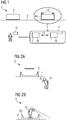
- Figure 1 shows an airport baggage handling system 2 according to an embodiment of the invention. Luggage items are moved along a conveying path 4 on transport devices 8 configured as containers 8 or differently.
- a transport device 8 designed as a measuring transport device 8m comprises detectors 10 for recording images 12 of the airport baggage handling system 2, the positioning of the measuring transport device 8m on the conveyor line 4 and the positioning of the detector 10 on the measuring transport device 8m, field of view and Resolution of the detector 10 define a location stamp 16 assigned to each image 12.
- At least one further detection device is arranged on the measuring transport device 8m and encompassed by the conveyor system.
- the further detection device detects, for example, oscillations and / or vibrations and / or temperature and / or smoke (non-exhaustive list) and sends the measured values to the background system 6, which analyzes the measured values and signals changes and / or abnormalities with a message.
- the background system 6 can also receive further measured values from stationary detection devices or otherwise.
- the transport devices 8 are active transport units 8 (and thus transport means 8 for active transport, e.g. AGV) or passive transport units 8 (and thus transport aids / conveying aids 8 for passive transport, e.g. transport trays without their own drive).
- Active conveyor units 8 have a motor or some other drive and travel on their conveyor line 4 automatically, which means that the conveyor line 4 itself is quite inexpensive and uncomplicated becomes realizable and is easy to maintain.
- Passive conveyor units 8 are driven by the conveyor line 4 itself, typically via belts and / or rollers, and therefore require a more complex route, but have much cheaper containers (mostly simple plastic tubs).
- the transport devices 8 comprise an active or passive load suspension device.
- the conveyor system 2 is adapted for transport devices 8 such as Destination Coded Vehicles (DCV) or automated guided vehicles (AGV).
- the conveyor system 2 is designed as an individual conveyor system.
- the conveyor line 4 can be completely or at least partially overlapping the same for all transport devices 8, 8m of the system (for example, in the case of a conveyor belt and passive transport devices 8) or different transport devices 8, 8m have individual, only very little or not at all overlapping conveyor lines 4 on the Conveyance level of the conveyor system 2 (for example, with active transport devices 8).
- Images 12 with the same location stamp 16 are therefore always recorded from the same perspective with an identical viewing angle.
- a time stamp t is also assigned to each recorded image 12.
- images 12, 12 'with identical location stamps 16 and time stamps t, t' that differ from one another can be used to analyze changes in the status of airport baggage handling system 2.
- the location stamp 16 can be obtained from location information of the transport device 8 that is typically already recorded in an airport baggage conveyor system 2 (in the case of direction coded vehicles, the location information is usually transmitted regularly to a background system 6 anyway).
- the measuring transport device 8m is designed as a conventional transport device 8 plus image display device (camera) 10 or as a special measuring transport device 8m with additional functionality.
- An analysis of the images 12, 12 ′ with identical location stamps 16 is carried out by a background system 6.
- the background system 6 is either at least partially arranged on the measuring transport device 8m, so that only the result of the analysis has to be transmitted, or the images 12, 12 'are transmitted to a stationary background system 6 and analyzed there.
- data are preferably transmitted wirelessly.
- Their time stamps t, t 'and their location stamps 16, 16' are transmitted together with the images 12, 12 '.
- the analysis determines a change in the state of the images 12, 12 ', with changes in the state of the conveyor system 2 itself (loosening screw, changed temperature of areas / parts of the conveyor system 2 and signs of wear and tear that can be identified as a result and / or otherwise, ...) and / or also abandoned or forgotten items (items of luggage and / or transport devices 8, 8m that have fallen from the conveyor line 4, broken and fallen parts of the conveyor system 2, forgotten maintenance items such as screwdrivers or the like, ).
- the background system detects a change in status between images 12, 12 'with the same location stamp 16 and time stamps t, t' that differ from one another, this is signaled with a message and transmitted to a computer 18, which can be included in the background system 6, so that a human assessment of this change of state can take place and determines the urgency of the maintenance of this change of state can be. With an appropriate configuration of the background system 6, this assessment can also be carried out automatically.
- Figure 2a shows a stationary status monitoring in which an observer 10 or detector 10 (human and / or machine) monitors the conveyor line 4 and the conveyor system 2 from a perspective that does not move with the transport device 8.
- the transport device 8 moves past the detector 10, so that in particular the state of the transport device 8 and of the small part of the conveyor line 4 which is in the field of view of the detector 10 is monitored.
- the detector 10 In order to image the entire conveying path 4, the detector 10 must move along the conveying path 4.
- the container fleet is monitored in a stationary manner, the observer 10 checking the containers 8 driving past.
- the positions at which images 12 are recorded are determined in a manner adapted to the respective conveyor system 2.
- the positions can be determined at regular intervals according to a grid - with another image 12 being recorded when the measuring transport device 8m passes again at the same point and with the same perspective (corresponds to the same location stamp 16).
- the spacing of the grid points is determined in a manner adapted to the imaging accuracy of the images 12 and their field of view.
- Figure 2b shows a condition monitoring system according to the invention that moves with it, in which the detector 10 moves together with the measuring transport device 8m.
- the measuring transport device 8m differs from the normal transport device 8 at least in that the measuring transport device 8m has a detector (image creation device) 10.
- the detector 10 moves together with the measuring transport device 8m along the conveyor line 4 and the sections lying to the side and in front of or behind the conveyor line 4 can be visually monitored.
- the measuring transport device 8m can also comprise, in addition to an optical detector 10, a vibration sensor or the like as a further detector.
- the data recorded by this additional detector are also analyzed by the background system 6.
- the state of the conveyor system 2 itself is ascertained by an observer 10 who travels with the measuring transport device 8m along the conveyor line 4.
- the components of the conveyor system 2 can be checked which are in the viewing angle of the observer 10 during the passage. By selecting the positioning of the observer 10 and his viewing angle, the area of the conveyor system 2 that can be analyzed to determine changes in state is determined. Images 12, temperatures, vibrations or distances, for example, can be viewed, viewed and analyzed.
- regular status measurements are carried out on the basis of the images 12 that have been recorded by the measuring transport device 8m, so that the system components, in particular critical components of the conveyor system 2 are monitored.
- the images 12, which can include thermal images, RGB images (visual images), vibration and sound measurements, are recorded, collected on an evaluation server 6 and analyzed.
- the evaluation server 6 can additionally receive further sensory data of the conveyor system 2 from other stationary and / or mobile detectors 10 '. The analysis is transmitted to the system operator / operator.
- the surveys that is to say the recording of images 12, 12 'and their analysis, take place regularly (daily, weekly or on every or every nth passage of the measuring transport device 8m). Since the detector 10 is carried along with the normal transport devices 8 on its measuring transport device 8m, surveys can be carried out without changes to the operating plan of the airport baggage handling system 2 being necessary.
- Components that can typically be detected by an image 12 and can be analyzed in a meaningful way for the reliability of the airport baggage handling system 2 are listed below.
- Motor drive, pulley and bearing temperature can be examined for changes in state using thermal images 12, 12 '.
- Incorrect assembly can be detected by visual image analysis.
- Loosening screw heads can be recognized by tracking a rotary movement of these same screw heads in subsequent images 12, 12 '(same location stamp 16, time stamps t, t' that differ from one another). Changes in the vibration pattern between conveyor line transitions and connections can be measured.
- Foreign bodies can be recognized on the basis of the images 12, since they are indicated on an image 12 by worn belts or other signs of wear and tear on parts subject to wear.
- Images 12 are reliably recorded for each decisive system component.
- the analysis by the background system can include post-processing by image processing of individual images 12 or of at least two images 12, 12 'recorded at different times t, t' but with the same location stamp 16. In this way, changes can be quantified and recognized over time.
- the solution according to the invention detects changes in the state of individual components by comparing current images 12 with historical images 12 'acquired at an earlier point in time t'. If changes in status are detected, this is signaled with a message and the status change detected is classified with regard to its urgency for further, more precise analysis. With this urgency queuing, the system 2 can accommodate changes due to environmental conditions, e.g. B. Changes in the ambient temperature, take into account. A message can also be triggered if a component differs significantly from other components of the same type within the system 2.
- the human or machine operator is given an overview of the current and historical images 12, 12 'and if necessary, further relevant, current and historical system data (ambient temperature, etc.) are made available with which the historical images 12 ', possibly including current measurement data, can be searched and checked. This allows the operator to judge whether a physical inspection or maintenance event should be triggered via a new work order list. In a subsequent shift, other operators can also closely monitor the components on the basis of which a message was triggered and any entries made by the previous operator in this work order list and, if necessary, adjust the order of this work order list.
- current and historical system data ambient temperature, etc.
- decisions and measures taken by an operator are fully checked and stored on the basis of a message from the background system 6.
- An open work order in the work order list is retained until the maintenance of this work order has been completed and future status monitors have provided evidence that the component in question has been reset to a normal state that does not result in a status change being recognized by the background system 6.
- the operator can be allowed to re-examine historical analyzes. These can be compared with the analyzes and / or measurements collected since the maintenance task was completed, so that valuable confirmation of a successful maintenance task can be obtained.
- the state or the image 12 can be used as a future new reference for new images 12 and measurements immediately after the maintenance task has been completed.
- the solution according to the invention offers a very reliable system 2 and method which continuously supplies a background system 6, which includes a database for storage and access, with images 12 and, if necessary, additional device temperature, device contour and device displacement data, so that wear or impending problems that can possibly lead to downtime, can be detected at an early stage. Monitoring the condition of the conveyor system 2 can thus be carried out in an uncomplicated and reliable manner.
Abstract
Zur Zustandsüberwachung beim Betreiben eines Fördersystems (2) nimmt eine Mess-Transportvorrichtung (8m), die entlang einer Förderstrecke (4) transportiert wird, Abbilder (12) des Fördersystems (2) auf, die mit einem Zeitstempel (t) und Ortsstempel (16) versehen und an ein Hintergrundsystem (6) übermittelt werden. Im Hintergrundsystem (6) werden die Abbilder (12) einer Analyse unterzogen, wobei Abbilder (12) mit gleichem Ortsstempel (16) miteinander verglichen werden und Abweichungen zwischen den Abbildern (12) mit gleichem Ortsstempel (16) als Zustandsveränderung des Fördersystems (2) erkannt und mit einer Meldung signalisiert werden.To monitor the status of a conveyor system (2), a measuring transport device (8m), which is transported along a conveyor line (4), records images (12) of the conveyor system (2) with a time stamp (t) and location stamp (16 ) and transmitted to a background system (6). In the background system (6), the images (12) are subjected to an analysis, images (12) with the same location stamp (16) being compared with one another and deviations between the images (12) with the same location stamp (16) as a change in the state of the conveyor system (2) recognized and signaled with a message.
Description
Die vorliegende Erfindung bezieht sich auf ein Verfahren zur Zustandsüberwachung beim Betreiben eines Fördersystems sowie auf ein Fördersystem mit Verschleißerkennung gemäß den unabhängigen Patentansprüchen.The present invention relates to a method for condition monitoring when operating a conveyor system and to a conveyor system with wear detection according to the independent claims.
Die vorliegende Erfindung betrifft insbesondere das technische Gebiet von Fördersystemen innerhalb eines Flughafens für Gepäckstücke und Stückgüter. Ein Ziel eines jeden Flughafenbetreibers ist es, Ausfälle bei der Gepäckabfertigung auf ein Minimum zu reduzieren. In der Praxis bedeutet dies, dass die Gepäckfördersysteme während des Betriebs "am Leben" gehalten werden und eine zeitbasierte Wartung ausserhalb der Betriebszeiten durchgeführt wird.The present invention relates in particular to the technical field of conveyor systems within an airport for pieces of luggage and general cargo. One of the goals of every airport operator is to reduce breakdowns in baggage handling to a minimum. In practice, this means that the baggage conveyor systems are kept "alive" during operation and time-based maintenance is carried out outside of operating hours.
Der Ausfall von nur einer Komponente kann zum Ausfall oder zur Verlangsamung wichtiger Bestandteile des Gepäckfördersystems führen. Dies kann für den betreffenden Flughafen und seine Passagiere sehr schnell zu Chaos führen, wobei Gepäckstücke ihre Flüge verpassen, und schlimmstenfalls Flugverspätungen und -ausfälle auftreten. Im Rahmen von leistungsbasierten Serviceverträgen mit strengen KPIs in Bezug auf Systemverfügbarkeit und -zuverlässigkeit können dem Gepäckfördersystem-Betreiber hierdurch hohe finanzielle Sanktionen verhängt werden.Failure of just one component can cause critical parts of the baggage handling system to fail or slow down. This can very quickly lead to chaos for the airport in question and its passengers, with pieces of luggage missing their flights and, in the worst case, flight delays and cancellations. In the context of performance-based service contracts with strict KPIs in relation to system availability and reliability, the baggage handling system operator can be subject to high financial sanctions.
Flughafen-Gepäckfördersysteme müssen schnell und hochgradig zuverlässig dazu in der Lage sein, mehrere Tausend Gepäckstücke pro Stunde zu sortieren und zu transportieren. Es existieren Systeme zur Überwachung und Steuerung technischer Prozesse mittels eines Computer-Systems, die bei der Überwachung von Flughafen-Gepäckfördersystemen zur Anwendung kommen. Diese Systeme können Ausfälle von Abschnitten eines Fördersystems anzeigen, beispielsweise wenn diese Abschnitte nicht mehr für die Gepäckabfertigung verfügbar sind. Unerwartete Systemausfälle sollten aber vermieden werden.Airport baggage handling systems must be able to sort and transport several thousand pieces of baggage per hour quickly and with great reliability. There are systems for monitoring and controlling technical processes by means of a computer system that are used to monitor airport baggage handling systems. These Systems can indicate failures of sections of a conveyor system, for example if these sections are no longer available for baggage handling. However, unexpected system failures should be avoided.
Die Bewirtschaftung von DCV-Systemen (Direction Coded Vehicles) ist besonders herausfordernd, da diese sehr lang sind (ca. 200 km in einem großen Flughafen) und tausende individuelle Komponenten umfassen. Potentielle Systemprobleme können anhand des visuellen Zustands der Komponenten, Fehlausrichtungen oder Ablagerungen oder unerwarteter Objekte wie verlorene Gepäckstücken oder bei Wartung zurückgelassene Werkzeuge identifiziert werden. Das Durchführen von Systembegehungen für die physische Inspektion und Überprüfung von Komponenten ist aufgrund der Systemlänge in einem DCV-System äußerst ressourcenintensiv und die Effektivität hängt in hohem Maße von den Fähigkeiten, der Ausbildung, der Sorgfalt und dem persönlichen Urteilsvermögen einzelner Mitarbeiter ab. Zudem ist die Systemumgebung für solche Vermessungen, insbesondere in DCV-Tunneln, oft schwierig und gefährlich, was die Häufigkeit verringert, mit der Systembegehungen durchgeführt werden. Zwangsläufig werden die Systembegehungen somit nicht oft genug durchgeführt, um bestehende Probleme zu erkennen. Zudem übersieht auch ein gut geschulter menschlicher Mitarbeiter Dinge (beispielsweise eine sich langsam lösende Schraube) oder interpretiert sie falsch, so dass Systembegehungen nicht ausreichen, um Systemausfälle zu verhindern.The management of DCV systems (Direction Coded Vehicles) is particularly challenging because they are very long (approx. 200 km in a large airport) and include thousands of individual components. Potential system problems can be identified by the visual condition of the components, misalignment or debris, or unexpected objects such as lost luggage or tools left behind during maintenance. Performing system visits for the physical inspection and verification of components is extremely resource-intensive due to the length of the system in a DCV system and its effectiveness depends to a large extent on the skills, training, care and personal judgment of individual employees. In addition, the system environment for such surveys, especially in DCV tunnels, is often difficult and dangerous, which reduces the frequency with which system inspections are carried out. Inevitably, the system inspections are not carried out often enough to identify existing problems. In addition, a well-trained human employee overlooks things (for example a slowly loosening screw) or interprets them incorrectly, so that system inspections are not sufficient to prevent system failures.
Der vorliegenden Erfindung liegt daher die Aufgabe zugrunde, eine schnelle, zuverlässige und regelmäßige Zustandsüberwachung in Fördersystemen, insbesondere Gepäckfördersystemen, noch insbesonderer in DCV-Systemen, zu ermöglichen. So können auftretende Wartungsprobleme frühzeitig erkannt und die operativen Ressourcen auf die Behebung und Wartung von Problemen und Ausfällen anstatt auf Brandbekämpfung von Ausfällen gelenkt werden. Diese Aufgabe wird durch die in den unabhängigen Ansprüchen beschriebenen Lösungen gelöst. Eine Verfügbarkeit dieser Lösung als Retrofit vereinfacht, insbesondere aufgrund der Systemlänge, die Installation und Wartung im Vergleich zu stationären Installationen.The present invention is therefore based on the object of enabling fast, reliable and regular status monitoring in conveyor systems, in particular baggage conveyor systems, and more particularly in DCV systems. In this way, occurring maintenance problems can be identified at an early stage and operational resources can be used to rectify and maintain problems and failures are directed to failures rather than firefighting. This object is achieved by the solutions described in the independent claims. The availability of this solution as a retrofit simplifies installation and maintenance compared to stationary installations, especially due to the length of the system.
Diese Aufgabe wird durch die in den unabhängigen Ansprüchen angegebenen Merkmale gelöst.This object is achieved by the features specified in the independent claims.
Die erfindungsgemäße Lösung sieht ein Verfahren zur Zustandsüberwachung beim Betreiben eines Fördersystems vor, das mindestens eine Förderstrecke umfasst, wobei entlang der Förderstrecke Transportvorrichtungen transportierbar sind. Durchgeführt werden die Verfahrensschritte:
- a) Aufnahme von Abbildern des Fördersystems, insbesondere der Förderstrecke, aufgenommen von einer sich entlang der Förderstrecke bewegenden Mess-Transportvorrichtung und Generieren eines Zeitstempels und eines Ortsstempels für jedes Abbild.
- b) Das aufgenommene Abbild wird zusammen mit einem Zeitstempel und einem Ortsstempel an ein Hintergrundsystem übermittelt.
- c) Im Hintergrundsystem werden die Abbilder einer Analyse unterzogen, wobei Abbilder mit gleichem Ortsstempel miteinander verglichen werden und Abweichungen zwischen den Abbildern mit gleichem Ortsstempel als Zustandsveränderung des Fördersystems erkannt und mit einer Meldung signalisiert werden.
- a) Recording of images of the conveyor system, in particular of the conveyor line, recorded by a measuring transport device moving along the conveyor line and generation of a time stamp and a location stamp for each image.
- b) The recorded image is transmitted to a background system together with a time stamp and a location stamp.
- c) In the background system, the images are subjected to an analysis, images with the same location stamp being compared with one another and discrepancies between the images with the same location stamp being recognized as a change in the state of the conveyor system and signaled with a message.
Das Verfahren eignet sich für sämtliche Fördersysteme, eignet sich aber insbesondere sehr gut für Flughafen-Gepäckfördersysteme, bei denen aufgrund ihrer Länge stationäre Installationen einen großen Installations- und Kostenaufwand bedeuten. Ein bestehendes Fördersystem muss einfach zusätzlich mit einer Mess-Transportvorrichtung ausgestattet werden und über ein zum Analysieren der Abbilder adaptiertes Hintergrundsystem verfügen, wobei entweder ein bereits vorhandenes Hintergrundsystem des Fördersystems hierzu angepasst oder ein hierfür eigens vorgesehenes Hintergrundsystem herangezogen werden kann.The method is suitable for all conveyor systems, but is particularly well suited for airport baggage conveyor systems in which, due to their length, stationary installations mean a great deal of installation and expense. An existing conveyor system simply has to be additionally equipped with a measuring transport device and have a background system adapted for analyzing the images, with either an existing background system of the conveyor system being adapted for this purpose or a background system specially provided for this being able to be used.
Unter einer Transportvorrichtung soll jegliche aktive oder passive Fördereinheit verstanden werden. Hierunter fallen sowohl Transportmittel zum aktiven Transport (z.B. ein fahrerloses Transportfahrzeug), die ihre Förderstrecke selbsttätig, aus eigener Kraft, befahren, als auch Transporthilfsmittel zum passiven Transport (z.B. Transportwannen) die auf einer Förderstrecke aufliegend von dieser, typischerweise über Bänder und/oder Rollen, angetrieben werden.A transport device should be understood to mean any active or passive conveying unit. This includes both means of transport for active transport (e.g. a driverless transport vehicle) that drive their conveyor line automatically, under their own power, as well as transport aids for passive transport (e.g. transport trays) that lie on a conveyor line from this, typically via belts and / or rollers , are driven.
Das Hintergrundsystem kann auf der Mess-Transportvorrichtung oder stationär angeordnet sein, bei einer stationären Anordnung bietet sich eine drahtlose Informationsübertragung an. Eine Anordnung auf dem Messvehikel hat den Vorteil, dass geringere Datenmengen (nur diejenigen Abbilder, anhand derer eine Zustandsveränderung festgestellt wird und die zu einer Meldung führen) übertragen werden müssen.The background system can be arranged on the measuring transport device or in a stationary manner; in the case of a stationary arrangement, wireless information transmission is possible. An arrangement on the measurement vehicle has the advantage that smaller amounts of data (only those images that are used to determine a change in status and that lead to a message) have to be transmitted.
Die Mess-Transportvorrichtung kann als gewöhnliche Transportvorrichtung plus Abbilderstellvorrichtung oder als spezielle Mess-Transportvorrichtung mit weiterer Funktionalität (z.B. Hintergrundsystem o.ä.) ausgestaltet sein. Die Aufnahme des Abbilds erfolgt aus der Perspektive der Mess-Transportvorrichtung, so dass die Positionierung der Abbilderstellvorrichtung entscheidend ist. Ein Ortsstempel umfasst die Positionierung und somit die Perspektive der Abbilderstellvorrichtung, so dass Abbilder mit gleichem Ortsstempel unabhängig vom Aufnahmezeitpunkt immer den gleichen Blickwinkel aus der gleichen Position liefern.The measuring transport device can be designed as a normal transport device plus image display device or as a special measuring transport device with additional functionality (eg background system or the like). The image is recorded from the perspective of the measuring transport device, so that the positioning of the image display device is decisive. A location stamp comprises the positioning and thus the perspective of the image display device, so that images with the same location stamp always deliver the same viewing angle from the same position regardless of the time of the recording.
Gemäß einer Ausführungsform wird der Ortsstempel erhalten von einer evtl. bereits vorhandenen Ortsinformation der Transportvorrichtung. Bei einem Direction Coded Vehicle wird die Ortsinformation typischerweise routinemäßig an ein übergeordnetes Hintergrundsystem übermittelt.According to one embodiment, the location stamp is obtained from any location information of the transport device that may already be present. In the case of a direction coded vehicle, the location information is typically routinely transmitted to a higher-level background system.
Die erfindungsgemäße Lösung kann durch verschiedene, jeweils für sich vorteilhafte und, sofern nicht anders ausgeführt, beliebig miteinander kombinierbarer Ausgestaltungen weiter verbessert werden. Auf diese Ausgestaltungsformen und die mit ihnen verbundenen Vorteile wird im Folgenden eingegangen.The solution according to the invention can be further improved by various configurations which are advantageous per se and, unless stated otherwise, can be combined with one another as desired. These embodiments and the advantages associated with them are discussed below.
Um wahlweise eine vollständige visuelle Abdeckung des Fördersystems, die mit einem höheren Analyseaufwand einhergeht, und/oder eine nur strategische visuelle Abdeckung, beispielsweise von besonders fehler- bzw. wartungsanfälligen Abschnitten, zu erzielen, können die Abbilder aufgenommenen werden an definierten Positionen des Fördersystems, beispielsweise vorgeben durch ein Raster und/oder Orientierungspunkte der Förderstrecke, so dass im zeitlichen Verlauf zwei oder mehr Abbilder mit identischem Ortsstempel entstehen. Diese Wahl kann kombiniert werden, um einen guten Kompromiss zwischen Analyseaufwand und genügend häufiger Zustandsüberwachung zu erreichen.In order to optionally achieve complete visual coverage of the conveyor system, which is associated with a higher analysis effort, and / or only strategic visual coverage, for example of particularly error-prone or maintenance-prone sections, the images can be recorded at defined positions of the conveyor system, for example specified by a grid and / or orientation points of the conveyor line, so that two or more images with an identical location stamp are created over time. This choice can be combined in order to achieve a good compromise between analysis effort and sufficiently frequent condition monitoring.
Positionierung, Genauigkeit und Blickwinkel der Kamera sind auf das entsprechende Fördersystem abgestimmt. Auf diese Weise kann das Fördersystem abgedeckt werden, ohne dass zu große Überschneidungen des abgedeckten Fördersystems auf den Abbildern notwendig sind.Positioning, accuracy and viewing angle of the camera are matched to the corresponding conveyor system. In this way, the conveyor system can be covered without the need for the covered conveyor system to overlap too much on the images.
Gemäß einer Ausführungsform kann das Abbild Wärmestrahlung und/oder optische Strahlung abbilden.According to one embodiment, the image can image thermal radiation and / or optical radiation.
Gemäß einer weiteren Ausführungsform können im Verfahrensschritt c) die Abbilder mit gleichem Ortsstempel analysiert werden hinsichtlich Abweichungen physikalischer Lage abgebildeter Teile und/oder Temperatur und/oder fehlender Teile.According to a further embodiment, in method step c) the images with the same location stamp can be analyzed with regard to deviations in the physical position of the imaged parts and / or temperature and / or missing parts.
Gemäß einer Ausführungsform kann die Mess-Transportvorrichtung mindestens eine Kamera zur Aufnahme der Abbilder erfassen, wobei die Kamera auf einer Transportvorrichtung angeordnet und befestigt ist und auf dieser entlang der Förderstrecke transportiert wird. Die Kamera agiert als Abbilderstellvorrichtung.According to one embodiment, the measuring transport device can capture at least one camera for recording the images, the camera being arranged and fastened on a transport device and being transported on this along the conveyor route. The camera acts as an imaging device.
Um einem menschlichen Operator eine Rückmeldung über die Art der erkannten Zustandsveränderung zu geben, der dann über das weitere Vorgehen, beispielsweise betreffend den Wartungsbedarf, dieser erkannten Zustandsveränderung entscheiden zu können, können die im Verfahrensschritt c) als Zustandsveränderung des Fördersystems erkannten Abbilder gemeinsam mit den erkannten Zustandsveränderung einem menschlichen Operator zur weiteren Entscheidung zugänglich gemacht werden.In order to provide a human operator with feedback on the type of change in status detected, who can then decide on the further course of action, for example with regard to the maintenance requirement, of this change in status, the images identified in method step c) as change in status of the conveyor system can be used together with the images identified Changes in state can be made available to a human operator for further decision-making.
Gemäß einer Ausführungsform kann die Transportvorrichtung ausgestaltet sein als Destination Coded Vehicle (DCV) oder als fahrerloses Transportfahrzeug (FTF - Automated Guided Vehicle, AGV).According to one embodiment, the transport device can be designed as a Destination Coded Vehicle (DCV) or as a driverless transport vehicle (FTF - Automated Guided Vehicle, AGV).
Hinsichtlich einer Vorrichtung wird die vorstehend genannte Aufgabe gelöst durch ein Fördersystem umfassend mindestens eine Förderstrecke zum Transport von Transportvorrichtungen, eine Mess-Transportvorrichtung und ein Hintergrundsystem. Entlang der Förderstrecke sind Transportvorrichtungen transportierbar.
- a) Die Mess-Transportvorrichtung ist ausgestaltet zur Aufnahme von Abbildern des Fördersystems, insbesondere der Förderstrecke, und zum Generieren eines Zeitstempels und eines Ortsstempels für jedes Abbild während einer Bewegung der Mess-Transportvorrichtung entlang der Förderstrecke.
- b) Die Mess-Transportvorrichtung ist ausgestaltet zur Übermittlung der aufgenommenen Abbilder zusammen mit dem jeweiligen Zeitstempel und dem jeweiligen Ortsstempel an das Hintergrundsystem.
- c) das Hintergrundsystem (6) ausgestaltet ist zum Analysieren der Abbilder (12) indem die Abbilder (12) mit gleichem Ortsstempel (16) miteinander verglichen werden und Abweichungen zwischen den Abbildern (12) mit gleichem Ortsstempel (16) als Zustandsveränderung des Fördersystems (2) erkannt und mit einer Meldung signalisiert werden.
- a) The measuring transport device is designed to record images of the conveyor system, in particular the conveyor line, and to generate a time stamp and a location stamp for each image while the measuring transport device is moving along the conveyor line.
- b) The measuring transport device is designed to transmit the recorded images together with the respective time stamp and the respective location stamp to the background system.
- c) the background system (6) is designed to analyze the images (12) in that the images (12) with the same location stamp (16) are compared with one another and deviations between the images (12) with the same location stamp (16) as a change in the state of the conveyor system ( 2) can be recognized and signaled with a message.
Gemäß einer Ausführungsform können die Abbilder aufgenommenen werden an definierten Positionen des Fördersystems, beispielsweise vorgeben durch ein Raster und/oder Orientierungspunkte der Förderstrecke, so dass im zeitlichen Verlauf zwei oder mehr Abbilder mit identischem Ortsstempel vorliegen.According to one embodiment, the images can be recorded at defined positions of the conveyor system, for example specified by a grid and / or orientation points of the conveyor line, so that two or more images with identical location stamps are present over time.
Gemäß einer Ausführungsform kann die Mess-Transportvorrichtung ausgestaltet sein zur Aufnahme von Abbildern die Wärmestrahlung und/oder optische Strahlung abbilden.According to one embodiment, the measuring transport device can be designed to record images that image thermal radiation and / or optical radiation.
Gemäß einer weiteren Ausführungsform kann das Hintergrundsystem ausgestaltet sein, die Abbilder mit gleichem Ortsstempel zu analysieren hinsichtlich Abweichungen physikalischer Lage abgebildeter Teile und/oder Temperatur und/oder fehlender Teile.According to a further embodiment, the background system can be designed to analyze the images with the same location stamp with regard to deviations in the physical position of the imaged parts and / or temperature and / or missing parts.
Gemäß noch einer weiteren Ausführungsform kann die Mess-Transportvorrichtung mindestens eine Kamera zur Aufnahme der Abbilder umfassen, wobei die Kamera auf einer Transportvorrichtung angeordnet und befestigt ist und auf dieser entlang der Förderstrecke transportierbar ist. Höhe und Linse der Kamera ist auf das Fördersystem abgestimmt und die Kamera kann in alle Richtungen ausgerichtet werden.According to yet another embodiment, the measuring transport device can comprise at least one camera for recording the images, the camera being arranged and fastened on a transport device and being transportable on this along the conveying path. The height and lens of the camera are matched to the conveyor system and the camera can be aligned in all directions.
Um eine erkannte Zustandsveränderung individuell zu beurteilen, können die als Zustandsveränderung des Fördersystems erkannten Abbilder gemeinsam mit der erkannten Zustandsveränderung einem menschlichen Operator zur weiteren Entscheidung zugänglich gemacht werden.In order to individually assess a recognized change in state, the images recognized as a change in the state of the conveyor system can be made accessible to a human operator for further decision-making, together with the recognized change in state.
Gemäß einer Ausführungsform kann das Fördersystem ein individuelles Fördersystem (Individual Carrier System ICS), beispielsweise ein Flughafen-Gepäckfördersystem, sein. Das Fördersystem ist so adaptiert für Transportvorrichtungen wie Destination Coded Vehicles (DCV) oder fahrerlose Transportfahrzeuge (FTF - Automated Guided Vehicle, AGV).According to one embodiment, the conveyor system can be an individual carrier system (ICS), for example an airport baggage conveyor system. The conveyor system is adapted for transport devices such as Destination Coded Vehicles (DCV) or driverless transport vehicles (FTF - Automated Guided Vehicle, AGV).
Gemäß einer weiteren Ausführungsform kann das Hintergrundsystem auf der Mess-Transportvorrichtung angeordnet sein und entlang der Förderstrecke transportierbar sein.According to a further embodiment, the background system can be arranged on the measuring transport device and can be transported along the conveyor line.
Ausführungsformen der Erfindung werden nachfolgend anhand der Figuren beispielsweise näher erläutert. Dabei zeigen:
- Figur 1
- ein erfindungsgemäßes Fördersystem;
- Figur 2a
- eine stationäre Zustandsüberwachung;
- Figur 2b
- eine mitbewegende Zustandsüberwachung.
- Figure 1
- a conveyor system according to the invention;
- Figure 2a
- stationary condition monitoring;
- Figure 2b
- a moving condition monitoring.
Gemäß einer weiteren Ausführungsform ist auf der Mess-Transportvorrichtung 8m noch mindestens eine weitere Detektionsvorrichtungen angeordnet und vom Fördersystem umfasst. Die weitere Detektionsvorrichtung detektiert beispielsweise Schwingungen und/oder Vibrationen und/oder Temperatur und/oder Rauch (nicht abschließende Aufzählung) und übersendet die gemessenen Werten an das Hintergrundsystem 6, welches die Messwerte analysiert und Änderungen und/oder Auffälligkeiten mit einer Meldung signalisiert. Das Hintergrundsystem 6 kann weitere Messwerte auch von stationären Detektionsvorrichtungen oder anderweitig erhalten.According to a further embodiment, at least one further detection device is arranged on the measuring
Die Transportvorrichtungen 8 sind aktive Fördereinheiten 8 (und somit Transportmittel 8 für einen aktiven Transport, z.B. AGV) oder passive Fördereinheiten 8 (und somit Transporthilfsmittel/Förderhilfsmittel 8 für einen passiven Transport, z.B. Transportwannen ohne eigenen Antrieb). Aktive Fördereinheiten 8 besitzen einen Motor oder einen anderen Antrieb und befahren ihre Förderstrecke 4 selbsttätig, wodurch die Förderstrecke 4 an sich recht günstig und unkompliziert realisierbar wird und einfach wartbar ist. Passive Fördereinheiten 8 werden von der Förderstrecke 4 selber, typischerweise über Bänder und/oder Rollen, angetrieben, benötigen dadurch eine komplexere Streckenführung, haben allerdings wesentlich günstigere Behälter (meist einfache Plastikwannen). Die Transportvorrichtungen 8 umfassen ein aktives oder passives Lastaufnahmemittel. Gemäß einer Ausführungsform ist das Fördersystem 2 adaptiert für Transportvorrichtungen 8 wie Destination Coded Vehicles (DCV) oder fahrerlose Transportfahrzeuge (FTF - automated guided vehicles, AGV). Das Fördersystem 2 ist gemäß einer Ausführungsform als individuelles Fördersystem ausgestaltet.The
Die Förderstrecke 4 kann komplett oder zumindest teilweise überlappend die gleiche sein für alle Transportvorrichtungen 8, 8m des Systems (beispielsweise bei einem Förderband und passiven Transportvorrichtungen 8) oder unterschiedliche Transportvorrichtungen 8, 8m weisen individuelle, nur sehr wenig oder gar nicht überlappende Förderstrecken 4 auf der Förderebene des Fördersystems 2 auf (beispielsweise bei aktiven Transportvorrichtungen 8).The
Abbilder 12 mit gleichem Ortsstempel 16 sind also stets aus der gleichen Perspektive mit identischem Blickwinkel aufgenommen. Jedem aufgenommenen Abbild 12 wird zudem ein Zeitstempel t zugeordnet. So können Abbilder 12, 12' mit identischem Ortsstempel 16 und voneinander abweichendem Zeitstempel t, t' zur Analyse von Zustandsänderungen des Flughafen-Gepäckfördersystem 2 herangezogen werden. Der Ortsstempel 16 kann von einer in einem Flughafen-Gepäckfördersystem 2 typischerweise bereits erfassten Ortsinformation der Transportvorrichtung 8 erhalten werden (bei Direction Coded Vehicles wird die Ortsinformation ohnehin meist regelmäßig an ein Hintergrundsystem 6 übermittelt).
Die Mess-Transportvorrichtung 8m ist als gewöhnliche Transportvorrichtung 8 plus Abbilderstellvorrichtung (Kamera) 10 oder als spezielle Mess-Transportvorrichtung 8m mit weiterer Funktionalität ausgestaltet.The measuring
Eine Analyse der Abbilder 12, 12' mit identischem Ortsstempel 16 wird von einem Hintergrundsystem 6 durchgeführt. Das Hintergrundsystem 6 ist entweder zumindest teilweise auf der Mess-Transportvorrichtung 8m angeordnet, so dass nur das Ergebnis der Analyse übermittelt werden muss, oder die Abbilder 12, 12' werden an ein stationäres Hintergrundsystem 6 übermittelt und dort analysiert. Bei einem stationären Hintergrundsystem 6 werden Daten vorzugsweise drahtlos übertragen. Zusammen mit den Abbildern 12, 12' werden ihre Zeitstempel t, t' und ihre Ortsstempel 16, 16' übertragen.An analysis of the
Die Analyse ermittelt eine Zustandsveränderung der Abbilder 12, 12', wobei als Zustandsveränderung Veränderungen des Fördersystems 2 selber (locker werdende Schraube, veränderte Temperatur von Gebieten/Teilen des Fördersystems 2 und hierdurch und/oder anderweitig erkennbare Abnutzungserscheinungen, ...) und/oder auch herrenlose bzw. vergessene Gegenstände (von der Förderstrecke 4 gefallene Gepäckstücke und/oder Transportvorrichtungen 8, 8m, kaputte und heruntergefallene Teile des Fördersystems 2, vergessene Wartungsgegenstände wie Schraubenzieher o.ä., ...). Wenn das Hintergrundsystem eine Zustandsveränderung zwischen Abbildern 12, 12' mit gleichem Ortsstempel 16 und voneinander abweichenden Zeitstempeln t, t' feststellt, wird dies mit einer Meldung signalisiert und an einen Computer 18, der von dem Hintergrundsystem 6 umfasst sein kann, übermittelt, damit eine menschliche Einschätzung dieser Zustandsveränderung stattfinden kann und die Dringlichkeit der Wartung ebendieser Zustandsveränderung bestimmt werden kann. Diese Einschätzung kann bei entsprechender Konfiguration des Hintergrundsystems 6 auch maschinell durchgeführt werden.The analysis determines a change in the state of the
Die Positionen, an welchen Abbilder 12 aufgenommen werden, werden angepasst an das jeweilige Fördersystem 2 bestimmt. Die Positionen können in regelmäßigen Abständen gemäß einem Raster festgelegt werden - wobei bei einem erneuten Durchgang der Mess-Transportvorrichtung 8m an derselben Stelle und bei gleicher Perspektive (entspricht dem gleichen Ortsstempel 16) ein weiteres Abbild 12 aufgenommen wird. Der Abstand der Rasterpunkte wird angepasst an die Abbildungsgenauigkeit der Abbilder 12 und ihr Blickfeld bestimmt. Je mehr Abbilder 12 entlang der Förderstrecke 4 aufgenommen werden, umso höher ist der Analyseaufwand. Ein guter Kompromiss kann es sein, in regelmäßigen zeitlichen Abständen, aber dennoch nicht bei jedem Durchgang der Mess-Transportvorrichtung 8m, das gesamte Fördersystem 2 (bzw. der von der Mess-Transportvorrichtung 8m her erfassbare Teil) vollständig visuell abzubilden und von besonders fehler- bzw. wartungsanfälligen Abschnitten oder von strategisch wichtigen Abschnitten (z.B. Weichen) bei jedem Durchgang der Mess-Transportvorrichtung 8m Abbilder 12 aufzunehmen und zu analysieren.The positions at which
Erfindungsgemäß werden regelmäßige Zustandsmessungen vorgenommen anhand von den Abbildern 12, die von der Mess-Transportvorrichtung 8m aus aufgenommenen worden sind, so dass die Systemkomponenten, insbesondere kritische Komponenten des Fördersystems 2, überwacht werden. Die Abbilder 12, welche Wärmebilder, RGB-Bilder (visuelle Bilder), Vibrations- und Schallmessungen umfassen können, werden erfasst, auf einem Auswertungsserver 6 gesammelt und analysiert. Der Auswertungsserver 6 kann zusätzlich weitere sensorische Daten des Fördersystems 2 von anderen, stationären und/oder mobilen Detektoren 10' erhalten. Die Analyse wird an den Systembetreiber/Operator übermittelt.According to the invention, regular status measurements are carried out on the basis of the
Die Erhebungen, also die Aufnahme von Abbildern 12, 12' und deren Analyse erfolgt regelmäßig (täglich, wöchentlich oder bei jeder oder jeder x-ten Durchfahrt der Mess-Transportvorrichtung 8m). Da der Detektor 10 auf seiner Mess-Transportvorrichtung 8m mit den normalen Transportvorrichtungen 8 mitgeführt wird, können Erhebungen durchgeführt werden, ohne dass Änderungen am Betriebsplan des Flughafen-Gepäckfördersystems 2 notwendig sind.The surveys, that is to say the recording of
Typischerweise von einem Abbild 12 erfassbar und für die Zuverlässigkeit des Flughafen-Gepäckfördersystems 2 sinnvollerweise analysierbare Komponenten werden im Folgenden aufgelistet. Motorantrieb, Riemenscheibe und Lagertemperatur können unter Verwendung von Wärmebildern 12, 12' auf Zustandsveränderungen untersucht werden. Fehlerhafte Montage kann durch visuelle Bildanalyse erkannt werden. Sich lösende Schraubenköpfe können durch Nachverfolgung einer Drehbewegung ebendieser Schraubenköpfe in nachfolgenden Abbildern 12, 12' (gleicher Ortsstempel 16, voneinander abweichende Zeitstempel t, t') erkannt werden. Veränderungen im Vibrationsmuster zwischen Förderstreckenübergängen und -verbindungen sind messbar. Fremdkörper können anhand der Abbilder 12 erkannt werden, da sie durch abgenutzte Riemen oder andere Abnutzungserscheinungen von Verschleißteilen auf einem Abbild 12 angedeutet werden. Der Zustand von Förderbändern der Förderstrecke 4 ist auf einem Abbild 12 mit entsprechendem Blickwinkel sichtbar und kann analysiert werden. Ebenso sind fehlende, falsch ausgerichtete oder zerbrochene Komponenten wie Halterungen, Führungsschienen o.ä. sicht- und analysierbar. Bei einem hinreichend gut zur Analyse eines spezifischen Fördersystems 2 trainiertem Hintergrundsystem 6 kann ein Vorhandensein eines unerwarteten Objekts bereits anhand eines einzelnen Abbilds 12 erkannt werden.Components that can typically be detected by an
Es werden zuverlässig Abbilder 12 (Wärmebilder und sichtbare Bilder) für jedes entscheidende Systemkomponente erfasst. Die Analyse durch das Hintergrundsystem kann eine Nachbearbeitung durch Bildverarbeitung von einzelnen Abbildern 12 oder von mindestens zwei zu unterschiedlichen Zeiten t, t' aber mit gleichem Ortsstempel 16 aufgenommen Abbildern 12, 12' umfassen. So können können Änderungen im Laufe der Zeit quantifiziert und erkannt werden.Images 12 (thermal images and visible images) are reliably recorded for each decisive system component. The analysis by the background system can include post-processing by image processing of
Die erfindungsgemäße Lösung erkennt Änderungen im Zustand einzelner Komponenten, indem aktuelle Abbilder 12 mit zu einem früheren Zeitpunkt t' erfassten, historischen Abbildern 12' verglichen werden. Wenn Zustandsänderungen festgestellt werden, wird dies mit einer Meldung signalisiert und die festgestellte Zustandsänderung wird hinsichtlich ihrer Dringlichkeit zur weiteren, genaueren Analyse eingeordnet. Bei dieser Einordnung in eine Warteschlange gemäß Dringlichkeit kann das System 2 Änderungen aufgrund von Umgebungsbedingungen, wie z. B. Änderungen der Umgebungstemperatur, berücksichtigen. Eine Meldung kann auch ausgelöst werden, wenn eine Komponente erheblich von anderen Komponenten desselben Typs innerhalb des Systems 2 abweicht.The solution according to the invention detects changes in the state of individual components by comparing
Dem menschlichen oder maschinellen Operator wird eine Übersicht der aktuellen und historischen Abbilder 12, 12' und allenfalls weiterer relevanter, aktueller und historischer Systemdaten (Umgebungstemperatur, etc.) zur Verfügung gestellt, mit der die historischen Abbilder 12', u.U. einschließlich aktueller Vermessungsdaten durchsucht und überprüft werden können. So kann der Operator beurteilen, ob ein physisches Inspektions- oder Wartungsereignis über eine neue Arbeitsauftragsliste ausgelöst werden soll. In einer nachfolgenden Schicht können auch andere Operatoren die Komponenten, anhand derer eine Meldung ausgelöst worden ist und allfällige Eingaben des früheren Operators in diese Arbeitsauftragsliste weiter genau beobachten und gegebenenfalls die Reihenfolge ebendieser Arbeitsauftragsliste anpassen.The human or machine operator is given an overview of the current and
Gemäß einer Ausführungsform werden anhand einer Meldung des Hintergrundsystems 6 von einem Operator getroffene Entscheidungen und Maßnahmen vollständig überprüft und abgespeichert. Ein offener Arbeitsauftrag der Arbeitsauftragsliste wird so lange beibehalten, bis die Wartung dieses Arbeitsauftrags abgeschlossen ist und zukünftige Zustandsüberwachungen einen Nachweis erbracht haben, dass die fragliche Komponente wieder in einen Normalzustand zurückversetzt worden ist, die nicht zu einer Erkennung als Zustandsveränderung durch das Hintergrundsystem 6 führt. Dem Operator kann erlaubt werden, historische Analysen erneut zu überprüfen. Diese können mit den seit Abschluss der Wartungsaufgabe gesammelten Analysen und/oder Messungen verglichen werden, so dass eine wertvolle Bestätigung für eine erfolgreiche Wartungsaufgabe erhalten werden kann. Durch den Abschluss eines Arbeitsauftrags aus der Arbeitsauftragsliste durch eine durchgeführte Wartung kann der Zustand bzw. das Abbild 12 direkt nach Abschluss der Wartungsaufgabe als zukünftige neue Referenz für neue Abbilder 12 und Messungen herangezogen werden.According to one embodiment, decisions and measures taken by an operator are fully checked and stored on the basis of a message from the
Die erfindungsgemäße Lösung bietet ein sehr zuverlässiges System 2 und Verfahren, welches ein Hintergrundsystem 6, welches eine Datenbank zur Abspeicherung und zum Zugriff umfasst, kontinuierlich mit Abbildern 12 und allenfalls zusätzlich Gerätetemperatur-, Gerätekontur- und Geräteverschiebungsdaten versorgt, sodass Verschleiß oder bevorstehende Probleme, die möglicherweise zu Ausfallzeiten führen können, frühzeitig erkannt werden können. Eine Zustandsüberwachung des Fördersystems 2 kann so unkompliziert und zuverlässig durchgeführt werden.The solution according to the invention offers a very
- 22
- FördersystemConveyor system
- 44th
- FörderstreckeConveyor line
- 66th
- HintergrundsystemBackground system
- 88th
- TransportvorrichtungTransport device
- 8m8m
- Mess-TransportvorrichtungMeasuring transport device
- 1010
- Kameracamera
- 1212th
- Abbildimage
- tt
- Zeitstempeltime stamp
- 1616
- OrtsstempelLocal stamp
- 1818th
- Computercomputer
Claims (15)
die Abbilder (12) aufgenommenen werden an definierten Positionen des Fördersystems (2), beispielsweise vorgeben durch ein Raster und/oder Orientierungspunkte der Förderstrecke (4), so dass im zeitlichen Verlauf zwei oder mehr Abbilder (12) mit identischem Ortsstempel (16) entstehen.The method of claim 1 wherein
the images (12) are recorded at defined positions of the conveyor system (2), for example specified by a grid and / or orientation points of the conveyor line (4), so that two or more images (12) with identical location stamps (16) are created over time .
das Abbild (12) Wärmestrahlung und/oder optische Strahlung abbildet.Method according to one of claims 1 to 2, characterized in that
the image (12) images thermal radiation and / or optical radiation.
im Verfahrensschritt c) werden die Abbilder (12) mit gleichem Ortsstempel (16) analysiert hinsichtlich Abweichungen physikalischer Lage abgebildeter Teile und/oder Temperatur und/oder fehlender Teile.Method according to one of claims 1 to 3, characterized in that
In method step c), the images (12) with the same location stamp (16) are analyzed with regard to deviations in the physical position of the imaged parts and / or temperature and / or missing parts.
die Mess-Transportvorrichtung (8m) mindestens eine Kamera (10) zur Aufnahme der Abbilder (12) umfasst, wobei die Kamera (10) auf einer Transportvorrichtung (8) angeordnet und befestigt ist und auf dieser entlang der Förderstrecke (4) transportiert wird.Method according to one of claims 1 to 4, characterized in that
the measuring transport device (8m) comprises at least one camera (10) for recording the images (12), the camera (10) being arranged and fastened on a transport device (8) and being transported along the conveyor line (4) on this.
die im Verfahrensschritt c) als Zustandsveränderung des Fördersystems (2) erkannten Abbilder (12) gemeinsam mit den erkannten Zustandsveränderung einem menschlichen Operator zur weiteren Entscheidung zugänglich gemacht werden.A method according to any one of claims 1 to 5, wherein
the images (12) recognized in method step c) as a change in the state of the conveyor system (2), together with the recognized change in state, are made available to a human operator for further decision-making.
die Transportvorrichtung (8) ausgestaltet ist als Destination Coded Vehicle (DCV) oder als fahrerloses Transportfahrzeug (FTF - Automated Guided Vehicle, AGV).Method according to one of claims 1 to 6, characterized in that
the transport device (8) is designed as a Destination Coded Vehicle (DCV) or as a driverless transport vehicle (FTF - Automated Guided Vehicle, AGV).
die Abbilder (12) aufgenommenen werden an definierten Positionen des Fördersystems (2), beispielsweise vorgeben durch ein Raster und/oder Orientierungspunkte der Förderstrecke (4), so dass im zeitlichen Verlauf zwei oder mehr Abbilder (12) mit identischem Ortsstempel (16) vorliegen.Conveyor system (2) according to claim 8, wherein
the images (12) recorded are at defined positions of the conveyor system (2), for example specified by a grid and / or orientation points of the conveyor line (4), so that two or more images (12) with an identical location stamp (16) are available over time .
dadurch gekennzeichnet, dass
die Mess-Transportvorrichtung (8m) ausgestaltet ist zur Aufnahme von Abbildern (12) die Wärmestrahlung und/oder optische Strahlung abbilden.Conveyor system (2) according to one of claims 8 to 9,
characterized in that
the measuring transport device (8m) is designed to record images (12) which image thermal radiation and / or optical radiation.
dadurch gekennzeichnet, dass
das Hintergrundsystem (6) ausgestaltet ist, die Abbilder (12) mit gleichem Ortsstempel (16) zu analysieren hinsichtlich Abweichungen physikalischer Lage abgebildeter Teile und/oder Temperatur und/oder fehlender Teile.Conveyor system (2) according to one of claims 8 to 10,
characterized in that
the background system (6) is designed to analyze the images (12) with the same location stamp (16) with regard to deviations in the physical position of the imaged parts and / or temperature and / or missing parts.
dadurch gekennzeichnet, dass
die Mess-Transportvorrichtung (8m) mindestens eine Kamera (10) zur Aufnahme der Abbilder (12) umfasst, wobei die Kamera (10) auf einer Transportvorrichtung (8) angeordnet und befestigt ist und auf dieser entlang der Förderstrecke (4) transportierbar ist.Conveyor system (2) according to one of claims 8 to 11,
characterized in that
the measuring transport device (8m) comprises at least one camera (10) for recording the images (12), wherein the camera (10) is arranged and fastened on a transport device (8) and can be transported on this along the conveyor line (4).
dadurch gekennzeichnet, dass
die als Zustandsveränderung des Fördersystems (2) erkannten Abbilder (12) gemeinsam mit der erkannten Zustandsveränderung einem menschlichen Operator zur weiteren Entscheidung zugänglich gemacht werden.Conveyor system (2) according to one of claims 8 to 12,
characterized in that
the images (12) recognized as a change in the state of the conveyor system (2), together with the recognized change in state, are made accessible to a human operator for further decision-making.
dadurch gekennzeichnet, dass
das Fördersystem (2) ein individuelles Fördersystem (2) (Individual Carrier System ICS), beispielsweise ein Flughafen-Gepäckfördersystem, ist.Conveyor system (2) according to one of claims 8 to 13,
characterized in that
the conveyor system (2) is an individual conveyor system (2) (Individual Carrier System ICS), for example an airport baggage conveyor system.
dadurch gekennzeichnet, dass
das Hintergrundsystem (6) auf der Mess-Transportvorrichtung (8m) angeordnet ist und entlang der Förderstrecke (4) transportierbar ist.Conveyor system (2) according to one of claims 8 to 14,
characterized in that
the background system (6) is arranged on the measuring transport device (8m) and can be transported along the conveyor line (4).
Priority Applications (1)
| Application Number | Priority Date | Filing Date | Title |
|---|---|---|---|
| EP19203228.2A EP3808687A1 (en) | 2019-10-15 | 2019-10-15 | Method for monitoring the sate of a conveying system and conveying system with state monitoring |
Applications Claiming Priority (1)
| Application Number | Priority Date | Filing Date | Title |
|---|---|---|---|
| EP19203228.2A EP3808687A1 (en) | 2019-10-15 | 2019-10-15 | Method for monitoring the sate of a conveying system and conveying system with state monitoring |
Publications (1)
| Publication Number | Publication Date |
|---|---|
| EP3808687A1 true EP3808687A1 (en) | 2021-04-21 |
Family
ID=68281024
Family Applications (1)
| Application Number | Title | Priority Date | Filing Date |
|---|---|---|---|
| EP19203228.2A Withdrawn EP3808687A1 (en) | 2019-10-15 | 2019-10-15 | Method for monitoring the sate of a conveying system and conveying system with state monitoring |
Country Status (1)
| Country | Link |
|---|---|
| EP (1) | EP3808687A1 (en) |
Cited By (1)
| Publication number | Priority date | Publication date | Assignee | Title |
|---|---|---|---|---|
| CN113682763A (en) * | 2021-09-01 | 2021-11-23 | 陕西竹园嘉原矿业有限公司 | Intelligent speed regulation and foreign matter identification system for coal flow transportation |
Citations (5)
| Publication number | Priority date | Publication date | Assignee | Title |
|---|---|---|---|---|
| WO2002055362A1 (en) * | 2001-01-15 | 2002-07-18 | Forsythe, Wayne, Jeffrey | Railway safety system |
| US20120274772A1 (en) * | 2011-04-27 | 2012-11-01 | Trimble Navigation Limited | Railway Track Monitoring |
| US20160152416A1 (en) * | 2013-07-15 | 2016-06-02 | Thomas FUHLBRIDGE | Conveyor Inspection With Unmanned Vehicle Carying Sensor Structure |
| US20190039633A1 (en) * | 2017-08-02 | 2019-02-07 | Panton, Inc. | Railroad track anomaly detection |
| US20190193946A1 (en) * | 2017-12-22 | 2019-06-27 | Flexible Steel Lacing Company | Apparatus and method for monitoring conveyor systems |
-
2019
- 2019-10-15 EP EP19203228.2A patent/EP3808687A1/en not_active Withdrawn
Patent Citations (5)
| Publication number | Priority date | Publication date | Assignee | Title |
|---|---|---|---|---|
| WO2002055362A1 (en) * | 2001-01-15 | 2002-07-18 | Forsythe, Wayne, Jeffrey | Railway safety system |
| US20120274772A1 (en) * | 2011-04-27 | 2012-11-01 | Trimble Navigation Limited | Railway Track Monitoring |
| US20160152416A1 (en) * | 2013-07-15 | 2016-06-02 | Thomas FUHLBRIDGE | Conveyor Inspection With Unmanned Vehicle Carying Sensor Structure |
| US20190039633A1 (en) * | 2017-08-02 | 2019-02-07 | Panton, Inc. | Railroad track anomaly detection |
| US20190193946A1 (en) * | 2017-12-22 | 2019-06-27 | Flexible Steel Lacing Company | Apparatus and method for monitoring conveyor systems |
Cited By (1)
| Publication number | Priority date | Publication date | Assignee | Title |
|---|---|---|---|---|
| CN113682763A (en) * | 2021-09-01 | 2021-11-23 | 陕西竹园嘉原矿业有限公司 | Intelligent speed regulation and foreign matter identification system for coal flow transportation |
Similar Documents
| Publication | Publication Date | Title |
|---|---|---|
| EP2937279B1 (en) | Freight loading system for loading and unloading of an item of freight, method for creating and/or updating a loading plan | |
| EP2212180B1 (en) | Determining the remaining service life of a vehicle component | |
| EP2076458B1 (en) | Device for monitoring a conveying system | |
| EP1390779B1 (en) | X-ray system comprising an x-ray source, a detector assembly and an aperture | |
| EP3625740B1 (en) | System and method for controlling a material flow at an intersection | |
| EP2444320A2 (en) | Freight loading system and method for detecting a movement of an item of freight on a freight deck | |
| EP3517398B1 (en) | Method for interior state monitoring, as well as a vehicle having interior state monitoring device | |
| WO2018087341A1 (en) | Inspection method, data processing system and inspection system for inspecting a vehicle in the operating state | |
| EP3445538B1 (en) | Method for controlling a plurality of mobile driverless manipulator systems | |
| DE102016224212A1 (en) | Automated free space detection using differential analysis for vehicles | |
| EP3401702B1 (en) | Sensor system | |
| EP3808687A1 (en) | Method for monitoring the sate of a conveying system and conveying system with state monitoring | |
| EP0994761B1 (en) | Shelving | |
| DE102011078191A1 (en) | Apparatus for monitoring cargo and for displaying loading information through airport luggage-loading station, has optical imaging unit that captures images of cargo at loading point at loading station, and transfer point | |
| EP3670007B1 (en) | Method for determining a state of a sorting installation, functional unit and sorting installation | |
| EP2835326B1 (en) | Picking system equiped with connectable storing modules, access detection and position sensors | |
| EP4157762A1 (en) | Method for the machine-based determination of the functional state of support rollers of a belt conveyor system, computer program and machine-readable data carrier | |
| DE102019107462A1 (en) | System and method for the automated checking of the functional status of components of a transport network in an intralogistics system | |
| EP3291152A1 (en) | Monitoring of a transport path | |
| DE102020212604A1 (en) | Method for inspecting a facility, preferably a conveyor system | |
| EP3581528B1 (en) | Device and method for monitoring the maintenance status of a conveyor | |
| BE1027171B1 (en) | Method and device for the automated operation of a material extraction system that can be used primarily in open-cast mining | |
| EP3367128B1 (en) | Surveillance arrangement | |
| WO2021213796A1 (en) | Device and method for ascertaining a usage behavior of a passenger when using a public means of transportation | |
| DE102020108460A1 (en) | Conveyor system and method for operating such a conveyor system |
Legal Events
| Date | Code | Title | Description |
|---|---|---|---|
| PUAI | Public reference made under article 153(3) epc to a published international application that has entered the european phase |
Free format text: ORIGINAL CODE: 0009012 |
|
| STAA | Information on the status of an ep patent application or granted ep patent |
Free format text: STATUS: THE APPLICATION HAS BEEN PUBLISHED |
|
| AK | Designated contracting states |
Kind code of ref document: A1 Designated state(s): AL AT BE BG CH CY CZ DE DK EE ES FI FR GB GR HR HU IE IS IT LI LT LU LV MC MK MT NL NO PL PT RO RS SE SI SK SM TR |
|
| AX | Request for extension of the european patent |
Extension state: BA ME |
|
| STAA | Information on the status of an ep patent application or granted ep patent |
Free format text: STATUS: THE APPLICATION IS DEEMED TO BE WITHDRAWN |
|
| 18D | Application deemed to be withdrawn |
Effective date: 20211022 |