EP3808662A1 - Adjustable aiming aircraft light assembly - Google Patents
Adjustable aiming aircraft light assembly Download PDFInfo
- Publication number
- EP3808662A1 EP3808662A1 EP19214304.8A EP19214304A EP3808662A1 EP 3808662 A1 EP3808662 A1 EP 3808662A1 EP 19214304 A EP19214304 A EP 19214304A EP 3808662 A1 EP3808662 A1 EP 3808662A1
- Authority
- EP
- European Patent Office
- Prior art keywords
- assembly
- reflector
- rail
- worm screw
- proximal end
- Prior art date
- Legal status (The legal status is an assumption and is not a legal conclusion. Google has not performed a legal analysis and makes no representation as to the accuracy of the status listed.)
- Granted
Links
Images




Classifications
-
- B—PERFORMING OPERATIONS; TRANSPORTING
- B64—AIRCRAFT; AVIATION; COSMONAUTICS
- B64D—EQUIPMENT FOR FITTING IN OR TO AIRCRAFT; FLIGHT SUITS; PARACHUTES; ARRANGEMENT OR MOUNTING OF POWER PLANTS OR PROPULSION TRANSMISSIONS IN AIRCRAFT
- B64D47/00—Equipment not otherwise provided for
- B64D47/02—Arrangements or adaptations of signal or lighting devices
- B64D47/04—Arrangements or adaptations of signal or lighting devices the lighting devices being primarily intended to illuminate the way ahead
-
- B—PERFORMING OPERATIONS; TRANSPORTING
- B64—AIRCRAFT; AVIATION; COSMONAUTICS
- B64D—EQUIPMENT FOR FITTING IN OR TO AIRCRAFT; FLIGHT SUITS; PARACHUTES; ARRANGEMENT OR MOUNTING OF POWER PLANTS OR PROPULSION TRANSMISSIONS IN AIRCRAFT
- B64D47/00—Equipment not otherwise provided for
- B64D47/02—Arrangements or adaptations of signal or lighting devices
-
- F—MECHANICAL ENGINEERING; LIGHTING; HEATING; WEAPONS; BLASTING
- F16—ENGINEERING ELEMENTS AND UNITS; GENERAL MEASURES FOR PRODUCING AND MAINTAINING EFFECTIVE FUNCTIONING OF MACHINES OR INSTALLATIONS; THERMAL INSULATION IN GENERAL
- F16H—GEARING
- F16H19/00—Gearings comprising essentially only toothed gears or friction members and not capable of conveying indefinitely-continuing rotary motion
- F16H19/02—Gearings comprising essentially only toothed gears or friction members and not capable of conveying indefinitely-continuing rotary motion for interconverting rotary or oscillating motion and reciprocating motion
- F16H19/04—Gearings comprising essentially only toothed gears or friction members and not capable of conveying indefinitely-continuing rotary motion for interconverting rotary or oscillating motion and reciprocating motion comprising a rack
-
- F—MECHANICAL ENGINEERING; LIGHTING; HEATING; WEAPONS; BLASTING
- F21—LIGHTING
- F21S—NON-PORTABLE LIGHTING DEVICES; SYSTEMS THEREOF; VEHICLE LIGHTING DEVICES SPECIALLY ADAPTED FOR VEHICLE EXTERIORS
- F21S41/00—Illuminating devices specially adapted for vehicle exteriors, e.g. headlamps
- F21S41/10—Illuminating devices specially adapted for vehicle exteriors, e.g. headlamps characterised by the light source
- F21S41/14—Illuminating devices specially adapted for vehicle exteriors, e.g. headlamps characterised by the light source characterised by the type of light source
- F21S41/141—Light emitting diodes [LED]
- F21S41/143—Light emitting diodes [LED] the main emission direction of the LED being parallel to the optical axis of the illuminating device
-
- F—MECHANICAL ENGINEERING; LIGHTING; HEATING; WEAPONS; BLASTING
- F21—LIGHTING
- F21S—NON-PORTABLE LIGHTING DEVICES; SYSTEMS THEREOF; VEHICLE LIGHTING DEVICES SPECIALLY ADAPTED FOR VEHICLE EXTERIORS
- F21S41/00—Illuminating devices specially adapted for vehicle exteriors, e.g. headlamps
- F21S41/10—Illuminating devices specially adapted for vehicle exteriors, e.g. headlamps characterised by the light source
- F21S41/14—Illuminating devices specially adapted for vehicle exteriors, e.g. headlamps characterised by the light source characterised by the type of light source
- F21S41/141—Light emitting diodes [LED]
- F21S41/151—Light emitting diodes [LED] arranged in one or more lines
-
- F—MECHANICAL ENGINEERING; LIGHTING; HEATING; WEAPONS; BLASTING
- F21—LIGHTING
- F21S—NON-PORTABLE LIGHTING DEVICES; SYSTEMS THEREOF; VEHICLE LIGHTING DEVICES SPECIALLY ADAPTED FOR VEHICLE EXTERIORS
- F21S41/00—Illuminating devices specially adapted for vehicle exteriors, e.g. headlamps
- F21S41/10—Illuminating devices specially adapted for vehicle exteriors, e.g. headlamps characterised by the light source
- F21S41/19—Attachment of light sources or lamp holders
- F21S41/192—Details of lamp holders, terminals or connectors
-
- F—MECHANICAL ENGINEERING; LIGHTING; HEATING; WEAPONS; BLASTING
- F21—LIGHTING
- F21S—NON-PORTABLE LIGHTING DEVICES; SYSTEMS THEREOF; VEHICLE LIGHTING DEVICES SPECIALLY ADAPTED FOR VEHICLE EXTERIORS
- F21S41/00—Illuminating devices specially adapted for vehicle exteriors, e.g. headlamps
- F21S41/30—Illuminating devices specially adapted for vehicle exteriors, e.g. headlamps characterised by reflectors
- F21S41/32—Optical layout thereof
- F21S41/36—Combinations of two or more separate reflectors
-
- F—MECHANICAL ENGINEERING; LIGHTING; HEATING; WEAPONS; BLASTING
- F21—LIGHTING
- F21S—NON-PORTABLE LIGHTING DEVICES; SYSTEMS THEREOF; VEHICLE LIGHTING DEVICES SPECIALLY ADAPTED FOR VEHICLE EXTERIORS
- F21S41/00—Illuminating devices specially adapted for vehicle exteriors, e.g. headlamps
- F21S41/30—Illuminating devices specially adapted for vehicle exteriors, e.g. headlamps characterised by reflectors
- F21S41/39—Attachment thereof
-
- F—MECHANICAL ENGINEERING; LIGHTING; HEATING; WEAPONS; BLASTING
- F21—LIGHTING
- F21S—NON-PORTABLE LIGHTING DEVICES; SYSTEMS THEREOF; VEHICLE LIGHTING DEVICES SPECIALLY ADAPTED FOR VEHICLE EXTERIORS
- F21S41/00—Illuminating devices specially adapted for vehicle exteriors, e.g. headlamps
- F21S41/50—Illuminating devices specially adapted for vehicle exteriors, e.g. headlamps characterised by aesthetic components not otherwise provided for, e.g. decorative trim, partition walls or covers
- F21S41/55—Attachment thereof
-
- B—PERFORMING OPERATIONS; TRANSPORTING
- B64—AIRCRAFT; AVIATION; COSMONAUTICS
- B64D—EQUIPMENT FOR FITTING IN OR TO AIRCRAFT; FLIGHT SUITS; PARACHUTES; ARRANGEMENT OR MOUNTING OF POWER PLANTS OR PROPULSION TRANSMISSIONS IN AIRCRAFT
- B64D2203/00—Aircraft or airfield lights using LEDs
-
- F—MECHANICAL ENGINEERING; LIGHTING; HEATING; WEAPONS; BLASTING
- F21—LIGHTING
- F21W—INDEXING SCHEME ASSOCIATED WITH SUBCLASSES F21K, F21L, F21S and F21V, RELATING TO USES OR APPLICATIONS OF LIGHTING DEVICES OR SYSTEMS
- F21W2104/00—Exterior vehicle lighting devices for decorative purposes
-
- F—MECHANICAL ENGINEERING; LIGHTING; HEATING; WEAPONS; BLASTING
- F21—LIGHTING
- F21W—INDEXING SCHEME ASSOCIATED WITH SUBCLASSES F21K, F21L, F21S and F21V, RELATING TO USES OR APPLICATIONS OF LIGHTING DEVICES OR SYSTEMS
- F21W2107/00—Use or application of lighting devices on or in particular types of vehicles
- F21W2107/30—Use or application of lighting devices on or in particular types of vehicles for aircraft
-
- F—MECHANICAL ENGINEERING; LIGHTING; HEATING; WEAPONS; BLASTING
- F21—LIGHTING
- F21Y—INDEXING SCHEME ASSOCIATED WITH SUBCLASSES F21K, F21L, F21S and F21V, RELATING TO THE FORM OR THE KIND OF THE LIGHT SOURCES OR OF THE COLOUR OF THE LIGHT EMITTED
- F21Y2115/00—Light-generating elements of semiconductor light sources
- F21Y2115/10—Light-emitting diodes [LED]
Definitions
- the present disclosure relates to aircraft lighting systems, and, more specifically, to aircraft light assembly with adjustable aiming.
- Aircraft often have one or more light assemblies which may be adjusted after installation on an aircraft by an aircraft manufacturer. Various manufacturers desire different light angles for their aircraft lighting systems.
- the space envelope reserved for the light assembly may include the volume occupied by the light assembly in any of the adjustable orientation.
- the aircraft light assembly comprises a reflector assembly including a reflector housing and a reflector; a printed wiring assembly (PWA) comprising a frame, a middle rail, and a light emitting diode (LED), the frame having a proximal end rail and a distal end rail, the middle rail extending from the proximal end rail to the distal end rail, the LED coupled to the middle rail and disposed proximate the reflector, the proximate end rail comprising a first PWA worm gear; and a bezel assembly comprising a frame and a first worm screw disposed in a slot of the frame, the first worm screw configured to translate the PWA in a first direction.
- PWA printed wiring assembly
- LED light emitting diode
- the first worm screw engages the first PWA worm gear.
- the reflector housing may comprise a proximal end having a proximal end slot, the first worm screw disposed within the proximal end slot.
- the reflector housing may comprise a proximal end having a reflector worm gear.
- the first worm screw may engage the reflector worm gear.
- the aircraft light assembly may further comprise a coating disposed between the frame of the PWA and the reflector assembly.
- the frame of the PWA may further comprise a first side rail extending from the proximal end rail and the distal end rail, and a second side rail opposite the first side rail and extending from the proximal end rail and the distal end rail, wherein the middle rail is disposed between the first side rail and the second side rail, and wherein the first side rail comprises a second PWA worm gear.
- the bezel assembly may further comprise a second worm screw, wherein the second worm screw engages the second PWA worm gear.
- the second worm screw may be configured to translate the PWA in a second direction, the second direction being perpendicular to the first direction, wherein the first direction and the second direction define a plane.
- the aircraft light assembly may comprise: a reflector assembly including a reflector housing and a reflector, the reflector housing comprising a proximal end, a distal end, a first side, and a second side, the first side extending from the proximal end to the distal end, and the second side extending from the proximal end to the distal end, the proximal end comprising a first reflector housing worm gear; a printed wiring assembly (PWA) comprising a frame and a LED configured to emit light toward the reflector; and a bezel assembly comprising a frame and a first worm screw disposed in a slot of the frame, the first worm screw configured to translate the reflector assembly in a first direction.
- PWA printed wiring assembly
- the first worm screw may engage the first reflector housing worm gear.
- the frame may comprise a proximal end rail having a proximal end slot, the first worm screw disposed within the proximal end slot.
- the frame may comprise a proximal end rail having a PWA worm gear.
- the first worm screw may engage the PWA worm gear.
- the light assembly may further comprise a coating disposed between the frame of the PWA and the reflector assembly.
- the first side may comprise a second reflector housing worm gear.
- the bezel assembly may further comprise a second worm screw, wherein the second worm screw engages the second reflector housing worm gear.
- the second worm screw may be configured to translate the reflector assembly in a second direction, the second direction being perpendicular to the first direction, wherein the first direction and the second direction define a plane.
- the aircraft may comprise: a light assembly comprising: a reflector assembly including a reflector housing and a reflector; a printed wiring assembly (PWA) comprising a frame and a light emitting diode (LED); and a bezel assembly comprising a frame, a first worm screw, and a second worm screw, the frame comprising a proximal end rail, a distal end rail, a side rail, a first side rail extending from the proximal end rail to the distal end rail, and a second side rail extending from the proximal end rail to the distal end rail and disposed opposite the first side rail, the first worm screw disposed in a first slot of the proximal end rail of the frame, the second worm screw disposed in a second slot of the first side rail of the frame, wherein the first worm screw is configured to translate at least one of the PWA and the reflector assembly in a first direction, and wherein the second worm screw is configured to translate at least
- the light assembly is configured to adjust a beam direction of the LED based on translating at least one of the PWA and the reflector assembly in a plane defined by the first direction and the second direction.
- any of the method or process descriptions may be executed in any order and are not necessarily limited to the order presented.
- any reference to singular includes plural embodiments, and any reference to more than one component or step may include a singular embodiment or step.
- any reference to attached, fixed, coupled, connected or the like may include permanent, removable, temporary, partial, full and/or any other possible attachment option.
- any reference to without contact (or similar phrases) may also include reduced contact or minimal contact. Surface shading lines may be used throughout the figures to denote different parts but not necessarily to denote the same or different materials.
- tail refers to the direction associated with a tail (e.g., the back end) of an aircraft, or generally, to the direction of exhaust of a gas turbine engine.
- forward refers to the direction associated with a nose (e.g., the front end) of the aircraft, or generally, to the direction of flight or motion.
- an aircraft 10 in accordance with various embodiments may comprise aircraft systems, for example, one or more landing gear such as landing gear 12, which may generally support aircraft 10 when aircraft is not flying, allowing aircraft 10 to taxi, take off, and land without damage.
- Aircraft 10 may include one or more exterior lamps 14 such as, for example, landing lights 16, taxi lights 17, and navigation lights 18.
- Exterior lamps 14 such as, for example, landing lights 16, taxi lights 17, and navigation lights 18.
- Aircraft 10 may include any number of other exterior lamps 14 such as logo lights, runway turnoff lights, engine scan lights, anti-collision lights, strobe lights, beacon lights, cargo compartment lights, obstruction lights, landing gear lights, and/or the like.
- the aircraft light assembly 100 may be a taxi light (e.g., taxi lights 17), a landing light (e.g., landing lights 16), or the like.
- the aircraft light assembly 100 may comprise a housing 110, a reflector assembly 120, a printed wiring assembly 130, a bezel assembly 140, and a lens assembly 150.
- the housing 110 may comprise a plurality of apertures 112. Each aperture in the plurality of apertures may be configured to couple the housing to an aircraft.
- each aperture in the plurality of apertures 112 may comprise an insert configured to receive a bolt and couple the housing to an aircraft.
- the housing 110 may be made of any material known in the art.
- the housing 110 could be made of plastic, aluminum, a composite material, or the like.
- the reflector assembly 120 comprises a reflector housing 122 and a first reflector 124.
- the reflector assembly 120 may comprise a second reflector 126 and a third reflector 128. Although illustrated with three reflectors, any number of reflectors is within the scope of this disclosure.
- Each reflector 124, 126, 128 may be coupled to the reflector housing 122 by any method known in the art, such as press fit, an adhesive, or the like.
- Each reflector 124, 126, 128 may be made of any material known in the art.
- each reflector 124, 126, 128 is made of aluminum, plastic, or the like.
- each reflector 124, 126, 128 may have a concave side proximate the printed wiring assembly 130.
- the printed wiring assembly 130 comprises a frame 132 defining a perimeter of the printed wiring assembly 130.
- the printed wiring assembly 130 further comprises a middle rail 134 extending from a proximal end 131 of the frame 132 in a first direction (e.g., the z-direction) to a distal end 133 of the frame 132.
- the middle rail 134 may be disposed between a first side rail 135 and a second side rail 136 of frame 132.
- each side rail 135, 136 of frame 132 may be substantially parallel to middle rail 134.
- middle rail 134 may comprise a protrusion 138 extending substantially perpendicular to middle rail 134.
- Protrusion 138 may be configured to receive a light emitting diode (LED).
- the printed wiring assembly 130 may be made of any material known in the art.
- the printed wiring assembly 130 may be made of polyimide epoxy, a metal core, such as aluminum-copper, or the like.
- the bezel assembly 140 comprises a frame 142, a fin support 144, and a fin 146.
- the fin support 144 may extend from a proximal end 141 of frame 142 in the first direction (i.e., the z-direction) to a distal end 143 of the frame 142.
- the frame 142 may further comprise a plurality of apertures 145 configured to couple the bezel assembly 140 to the housing 110 and to couple the reflector assembly 120 and/or the printed wiring assembly 130 to the housing assembly.
- the bezel assembly 140 may be configured to receive a first lens 152 of the lens assembly 150 between the fin support 144 and a first side rail 147 of frame 142.
- the bezel assembly 140 may be configured to receive a second lens 154 of the lens assembly 150 between the fin support 144 and a second side rail 149 of frame 142.
- the printed wiring assembly 300 comprises a frame 310, a middle rail 320, and a first light emitting diode (LED) 330.
- the frame 310 comprises a proximal end rail 312, a distal end rail 314, a first side rail 316, and a second side rail 318.
- Each rail of frame 310 may comprise a worm gear.
- proximal end rail 312 may comprise a proximal worm gear 313
- distal end rail 314 may comprise a distal worm gear 315.
- first side rail 316 may comprise a first side worm gear 317
- second side rail 318 may comprise a second side worm gear 319.
- a "worm gear” as described herein is a gear having teeth that twist either clockwise (e.g., a right hand helical gear) or teeth that twist counter-clockwise (e.g., a left hand helical gear).
- Each worm gear may be configured to interface with a worm screw from a bezel assembly to adjust a positioning of the printed wiring assembly 300.
- the printed wiring assembly 300 may further comprise a first support rail 340 extending from first side rail 316 to second side rail 318.
- the first support rail 340 may be disposed between proximal end rail 312 and distal end rail 314.
- the first support rail 340 may be proximate to distal end rail 314.
- the printed wiring assembly 300 may further comprise a second support rail 350 extending from first side rail 316 to second side rail 318.
- the second support rail 350 may be disposed between first support rail 340 and proximal end rail 312.
- the middle rail 320 may further comprise a first protrusion 322 extending towards first side rail 316 and disposed between first support rail 340 and distal end rail 314.
- the middle rail 320 may further comprise a second protrusion 324 extending towards second side rail 318 and disposed between second support rail 350 and proximal end rail 312.
- the printed wiring assembly 300 may further comprise a second LED 332 coupled to the first protrusion 322.
- the printed wiring assembly 300 may further comprise a third LED 334 coupled to the second protrusion 324.
- the first LED 330 is coupled to the middle rail 320 proximate a center of middle rail 320.
- the reflector assembly 400 comprises a reflector housing 410 and a first reflector 420.
- the reflector housing 410 comprises a reflector frame 411 including a proximal end 412, a distal end 414 opposite the proximal end 412, a first side 416 extending from the proximal end 412 to the distal end 414, and a second side 418 opposite the first side 416 and extending between the proximal end 412 and the distal end 414.
- Each side and each end of the reflector housing 410 may comprise a worm gear.
- proximal end 412 may comprise a proximal worm gear 413, and/or distal end 414 may comprise a distal worm gear 415.
- first side 416 may comprise a first side worm gear 417, and second side 418 may comprise a second side worm gear 419.
- a "worm gear" as described herein is a gear having teeth that twist either clockwise (e.g., a right hand helical gear) or teeth that twist counter-clockwise (e.g., a left hand helical gear).
- Each worm gear may be configured to interface with a worm screw from a bezel assembly to adjust a positioning of reflector assembly 400.
- the reflector assembly 400 may further comprise a second reflector 422 disposed between the first reflector 420 and distal end 414. Similarly, the reflector assembly 400 may further comprise a third reflector 424 disposed between the first reflector and proximal end 412.
- the bezel assembly 500 comprises a frame 510.
- the frame 510 comprises a proximal end rail 512, a distal end rail 514, a first side rail 516, and a second side rail 518.
- Each rail may comprise a slot configured to receive a worm screw.
- proximal end rail 512 may have a proximal end rail slot 513 and distal end rail 514 may have a distal end rail slot 515.
- first side rail 516 may have a first side rail slot 517 and second side rail 518 may have a second side rail slot 519.
- the bezel assembly 500 may further comprise a first worm screw 522 and a second worm screw 526.
- first worm screw 522 may be disposed in proximal end rail 512 and second worm screw 526 may be disposed in first side rail 516.
- first worm screw 522 is configured to engage proximal worm gear 313 of printed wiring assembly 300 and/or proximal worm gear 413 of reflector assembly 400.
- the first worm screw 522 may be configured to translate the printed wiring assembly 300 and/or the reflector assembly 400, and bezel assembly 500 along a first direction (e.g., along the x-axis).
- a user may rotate a head of first worm screw 522 counter-clockwise, the printed wiring assembly 300 may move opposite the first direction (e.g. in the - X direction).
- the second worm screw 526 may be configured to translate the printed wiring assembly 300 and/or the reflector assembly 400, and bezel assembly 500 along a second direction (e.g., along the z-axis).
- the second direction may be substantially perpendicular to the first direction.
- the proximal worm gear 313 of printed wiring assembly 300 may be configured to translate printed wiring assembly 300 in an opposite direction of proximal worm gear 413 of reflector assembly 400.
- a user may rotate a head of first worm screw 522 counter-clockwise, the printed wiring assembly 300 may move in the negative X direction and the reflector assembly 400 may move in the X-direction.
- bezel assembly 500 may be configured to translate in the same direction as the printed wiring assembly 300 or the reflector assembly 400.
- bezel assembly 500 may further comprise a third worm screw 524 disposed in distal end rail 514 of bezel assembly 500 and a fourth worm screw 528 disposed in second side rail 518 of bezel assembly 500.
- first worm screw 522 and third worm screw 524 are twisted in opposite directions to translate bezel assembly 500 in a first direction.
- first worm screw 522 may be twisted counter-clockwise and third worm screw 524 may be twisted clockwise to translate in the -X direction.
- printed wiring assembly 600 may be in accordance with the printed wiring assembly 300, except each worm gear is replaced with a respective slot.
- printed wiring assembly 600 comprises a frame 610 including a plurality of slots.
- the frame 610 comprises a proximal end rail 612, a distal end rail 614, a first side rail 616, and a second side rail 618.
- Each rail of frame 610 may comprise a slot.
- proximal end rail 612 may comprise a proximal slot 613 and distal end rail 614 may comprise a distal slot 615.
- first side rail 616 may comprise a first side slot 617
- second side rail 618 may comprise a second side slot 619.
- each slot is configured to have disposed therebetween a worm screw.
- each slot may be configured to remain separated from the worm screw.
- the reflector assembly 700 may be in accordance with reflector assembly 400, except each worm gear is replaced with a respective slot.
- the reflector assembly 700 comprises a reflector housing 710.
- the reflector housing 710 comprises a reflector frame 711 including a proximal end 712, a distal end 714 opposite the proximal end 712, a first side 716 extending from the proximal end 712 to the distal end 714, and a second side 718 opposite the first side 716 and extending between the proximal end 712 and the distal end 714.
- Each side and each end of the reflector housing 710 may comprise a slot.
- proximal end 712 may comprise a proximal slot 713, and/or distal end 714 may comprise a distal slot 715.
- first side 716 may comprise a first side slot 717, and second side 718 may comprise a second side slot 719.
- each slot is configured to have disposed therebetween a worm screw. In various embodiments, each slot may be configured to remain separated from the worm screw.
- the aircraft light assembly 800 comprises a printed wiring assembly 300, a reflector assembly 700, and a bezel assembly 500.
- a coating is disposed between printed wiring assembly 300 and reflector assembly 700.
- the coating may be disposed on the frame 310 of printed wiring assembly 300, on the reflector housing 710 of reflector assembly 700, or both.
- the coating is an acetal resin, or any other synthetic polymer known in the art.
- the coating may be configured to allow the printed wiring assembly 300 and bezel assembly 500 to translate relative to the reflector assembly 700 without binding due to friction.
- the aircraft light assembly 810 comprises a printed wiring assembly 600, a reflector assembly 400, and a bezel assembly 500.
- a first coating is disposed between printed wiring assembly 600 and reflector assembly 400.
- a second coating may also be disposed between the bezel assembly 500 and the printed wiring assembly 600.
- the first coating may be disposed on the frame 610 of the printed wiring assembly 600, on the reflector housing 410 of reflector assembly 400, or both.
- the second coating may be disposed on frame 510, on printed wiring assembly 600, or both.
- the first coating and the second coating are an acetal resin, or any other synthetic polymer known in the art.
- the first coating and the second coating may be configured to allow the reflector assembly 400 and bezel assembly 500 to translate relative to the printed wiring assembly 600 without binding up due to friction.
- the aircraft light assembly 820 comprises a printed wiring assembly 902, a reflector assembly 904, and a bezel assembly 500.
- Printed wiring assembly 902 may be a hybrid of printed wiring assembly 300 and printed wiring assembly 600 (e.g., printed wiring assembly 902 may have first side worm gear 317, second side worm gear 319, proximal end slot 613, and distal end slot 615) and reflector assembly 904 may be a hybrid of reflector assembly 400 and reflector assembly 700 (e.g., reflector assembly 904 may have a proximal end worm gear 413 and a distal end worm gear 415).
- a hybrid configuration, as described may allow the printed wiring assembly 902 to translate vertically only (i.e., along Z-axis from FIG.5 ) and reflector assembly 904 to translate horizontally only (i.e., along X-axis from FIG. 5 ), or vice versa.
- a coating is disposed between printed wiring assembly 902 and reflector assembly 904.
- the coating may be disposed on the frame of printed wiring assembly 902, on the reflector housing of reflector assembly 904, or both.
- the coating is an acetal resin, or any other synthetic polymer known in the art.
- the coating may be configured to allow the printed wiring assembly 300 and bezel assembly 500 to translate relative to the reflector assembly 700 without binding due to friction.
- an LED in a neutral position compared to an LED in a shifted position is illustrated.
- the reflector 910 directs the light projected from the LED 920A in the opposite direction of the initial direction (i.e., the reflector 910 reflects the emitted light directly back at the LED 920A along the Y-axis).
- the reflector 910 By translating LED 920B a shifted distance e along the x-axis a shifted beam direction may be achieved.
- a shifted beam direction 930 can be calculated as an angle ⁇ relative to the ⁇ -direction (e.g., angle ⁇ is equal to the arc-tangent of shifted distance e divided by distance d).
- aircraft light assemblies 800, 810, and 820 allow shifting of an LED relative to a respective reflector within 360° of a plane (e.g., X-Z plane), which allows more customizable beam directions for an aircraft lighting system.
- each element of reflector assembly 120 may alternatively be applied to lens assembly 150 to adjust lens assembly 150 relative to the various components of aircraft light assembly 100.
- references to "various embodiments,” “one embodiment,” “an embodiment,” “an example embodiment,” etc. indicate that the embodiment described may include a particular feature, structure, or characteristic, but every embodiment may not necessarily include the particular feature, structure, or characteristic. Moreover, such phrases are not necessarily referring to the same embodiment. Further, when a particular feature, structure, or characteristic is described in connection with an embodiment, it is submitted that it is within the knowledge of one skilled in the art to affect such feature, structure, or characteristic in connection with other embodiments whether or not explicitly described. After reading the description, it will be apparent to one skilled in the relevant art(s) how to implement the disclosure in alternative embodiments.
Landscapes
- Engineering & Computer Science (AREA)
- General Engineering & Computer Science (AREA)
- Physics & Mathematics (AREA)
- Microelectronics & Electronic Packaging (AREA)
- Optics & Photonics (AREA)
- Aviation & Aerospace Engineering (AREA)
- Mechanical Engineering (AREA)
- Non-Portable Lighting Devices Or Systems Thereof (AREA)
- Fastening Of Light Sources Or Lamp Holders (AREA)
Abstract
Description
- The present disclosure relates to aircraft lighting systems, and, more specifically, to aircraft light assembly with adjustable aiming.
- Aircraft often have one or more light assemblies which may be adjusted after installation on an aircraft by an aircraft manufacturer. Various manufacturers desire different light angles for their aircraft lighting systems. The space envelope reserved for the light assembly may include the volume occupied by the light assembly in any of the adjustable orientation.
- An aircraft light assembly is disclosed herein. The aircraft light assembly comprises a reflector assembly including a reflector housing and a reflector; a printed wiring assembly (PWA) comprising a frame, a middle rail, and a light emitting diode (LED), the frame having a proximal end rail and a distal end rail, the middle rail extending from the proximal end rail to the distal end rail, the LED coupled to the middle rail and disposed proximate the reflector, the proximate end rail comprising a first PWA worm gear; and a bezel assembly comprising a frame and a first worm screw disposed in a slot of the frame, the first worm screw configured to translate the PWA in a first direction.
- In various embodiments, the first worm screw engages the first PWA worm gear. The reflector housing may comprise a proximal end having a proximal end slot, the first worm screw disposed within the proximal end slot. The reflector housing may comprise a proximal end having a reflector worm gear. The first worm screw may engage the reflector worm gear. The aircraft light assembly may further comprise a coating disposed between the frame of the PWA and the reflector assembly. The frame of the PWA may further comprise a first side rail extending from the proximal end rail and the distal end rail, and a second side rail opposite the first side rail and extending from the proximal end rail and the distal end rail, wherein the middle rail is disposed between the first side rail and the second side rail, and wherein the first side rail comprises a second PWA worm gear. The bezel assembly may further comprise a second worm screw, wherein the second worm screw engages the second PWA worm gear. The second worm screw may be configured to translate the PWA in a second direction, the second direction being perpendicular to the first direction, wherein the first direction and the second direction define a plane.
- An aircraft light assembly is disclosed herein. The aircraft light assembly may comprise: a reflector assembly including a reflector housing and a reflector, the reflector housing comprising a proximal end, a distal end, a first side, and a second side, the first side extending from the proximal end to the distal end, and the second side extending from the proximal end to the distal end, the proximal end comprising a first reflector housing worm gear; a printed wiring assembly (PWA) comprising a frame and a LED configured to emit light toward the reflector; and a bezel assembly comprising a frame and a first worm screw disposed in a slot of the frame, the first worm screw configured to translate the reflector assembly in a first direction.
- In various embodiments, the first worm screw may engage the first reflector housing worm gear. The frame may comprise a proximal end rail having a proximal end slot, the first worm screw disposed within the proximal end slot. The frame may comprise a proximal end rail having a PWA worm gear. The first worm screw may engage the PWA worm gear. The light assembly may further comprise a coating disposed between the frame of the PWA and the reflector assembly. The first side may comprise a second reflector housing worm gear. The bezel assembly may further comprise a second worm screw, wherein the second worm screw engages the second reflector housing worm gear. The second worm screw may be configured to translate the reflector assembly in a second direction, the second direction being perpendicular to the first direction, wherein the first direction and the second direction define a plane.
- An aircraft is disclosed herein. The aircraft may comprise: a light assembly comprising: a reflector assembly including a reflector housing and a reflector; a printed wiring assembly (PWA) comprising a frame and a light emitting diode (LED); and a bezel assembly comprising a frame, a first worm screw, and a second worm screw, the frame comprising a proximal end rail, a distal end rail, a side rail, a first side rail extending from the proximal end rail to the distal end rail, and a second side rail extending from the proximal end rail to the distal end rail and disposed opposite the first side rail, the first worm screw disposed in a first slot of the proximal end rail of the frame, the second worm screw disposed in a second slot of the first side rail of the frame, wherein the first worm screw is configured to translate at least one of the PWA and the reflector assembly in a first direction, and wherein the second worm screw is configured to translate at least one of the PWA and the reflector assembly in a second direction, wherein the second direction is perpendicular to the first direction.
- In various embodiments, the light assembly is configured to adjust a beam direction of the LED based on translating at least one of the PWA and the reflector assembly in a plane defined by the first direction and the second direction.
- The foregoing features and elements may be combined in various combinations without exclusivity, unless expressly indicated otherwise. These features and elements as well as the operation thereof will become more apparent in light of the following description and the accompanying drawings. It should be understood, however, the following description and drawings are intended to be exemplary in nature and non-limiting.
- The subject matter of the present disclosure is particularly pointed out and distinctly claimed in the concluding portion of the specification. A more complete understanding of the present disclosure, however, may best be obtained by referring to the detailed description and claims when considered in connection with the figures, wherein like numerals denote like elements.
-
FIG. 1 illustrates an aircraft, in accordance with various embodiments; -
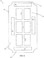
FIG. 2 illustrates an aircraft light assembly, in accordance with various embodiments; -
FIG. 3 illustrates a printed wiring assembly for use in an aircraft light assembly, in accordance with various embodiments; -
FIG. 4 illustrates a reflector assembly for use in an aircraft light assembly, in accordance with various embodiments; -
FIG. 5 illustrates a bezel assembly for use in an aircraft light assembly, in accordance with various embodiments; -
FIG. 6 illustrates a printed wiring assembly for use in an aircraft light assembly, in accordance with various embodiments; -
FIG. 7 illustrates a reflector assembly for use in an aircraft light assembly, in accordance with various embodiments; -
FIG. 8A illustrates an aircraft light assembly, in accordance with various embodiments; -
FIG. 8B illustrates an aircraft light assembly, in accordance with various embodiments; -
FIG. 8C illustrates an aircraft light assembly, in accordance with various embodiments; and -
FIG. 9 illustrates a comparison between a light emitting diode (LED) in a neutral position compared to a shifted position in a light assembly, in accordance with various embodiments. - All ranges and ratio limits disclosed herein may be combined. It is to be understood that unless specifically stated otherwise, references to "a," "an," and/or "the" may include one or more than one and that reference to an item in the singular may also include the item in the plural.
- The detailed description of exemplary embodiments herein makes reference to the accompanying drawings, which show exemplary embodiments by way of illustration. While these exemplary embodiments are described in sufficient detail to enable those skilled in the art to practice the exemplary embodiments of the disclosure, it should be understood that other embodiments may be realized and that logical changes and adaptations in design and construction may be made in accordance with this disclosure and the teachings herein. Thus, the detailed description herein is presented for purposes of illustration only and not limitation.
- The scope of the disclosure is defined by the appended claims and their legal equivalents rather than by merely the examples described. For example, the steps recited in any of the method or process descriptions may be executed in any order and are not necessarily limited to the order presented. Furthermore, any reference to singular includes plural embodiments, and any reference to more than one component or step may include a singular embodiment or step. Also, any reference to attached, fixed, coupled, connected or the like may include permanent, removable, temporary, partial, full and/or any other possible attachment option. Additionally, any reference to without contact (or similar phrases) may also include reduced contact or minimal contact. Surface shading lines may be used throughout the figures to denote different parts but not necessarily to denote the same or different materials.
- As used herein, "aft" refers to the direction associated with a tail (e.g., the back end) of an aircraft, or generally, to the direction of exhaust of a gas turbine engine. As used herein, "forward" refers to the direction associated with a nose (e.g., the front end) of the aircraft, or generally, to the direction of flight or motion.
- With reference to
FIG. 1 , anaircraft 10 in accordance with various embodiments may comprise aircraft systems, for example, one or more landing gear such as landing gear 12, which may generally supportaircraft 10 when aircraft is not flying, allowingaircraft 10 to taxi, take off, and land without damage.Aircraft 10 may include one or more exterior lamps 14 such as, for example, landinglights 16, taxi lights 17, andnavigation lights 18.Aircraft 10 may include any number of other exterior lamps 14 such as logo lights, runway turnoff lights, engine scan lights, anti-collision lights, strobe lights, beacon lights, cargo compartment lights, obstruction lights, landing gear lights, and/or the like. - With reference now to
FIG. 2 , an exploded view of an aircraft light assembly, in accordance with various embodiments, is illustrated. The aircraftlight assembly 100 may be a taxi light (e.g., taxi lights 17), a landing light (e.g., landing lights 16), or the like. In various embodiments, the aircraftlight assembly 100 may comprise ahousing 110, areflector assembly 120, a printedwiring assembly 130, abezel assembly 140, and alens assembly 150. - The
housing 110 may comprise a plurality ofapertures 112. Each aperture in the plurality of apertures may be configured to couple the housing to an aircraft. For example, each aperture in the plurality ofapertures 112 may comprise an insert configured to receive a bolt and couple the housing to an aircraft. Thehousing 110 may be made of any material known in the art. For example, thehousing 110 could be made of plastic, aluminum, a composite material, or the like. - The
reflector assembly 120 comprises areflector housing 122 and afirst reflector 124. In various embodiments, thereflector assembly 120 may comprise asecond reflector 126 and athird reflector 128. Although illustrated with three reflectors, any number of reflectors is within the scope of this disclosure. Eachreflector reflector housing 122 by any method known in the art, such as press fit, an adhesive, or the like. Eachreflector reflector reflector wiring assembly 130. - The printed
wiring assembly 130 comprises aframe 132 defining a perimeter of the printedwiring assembly 130. The printedwiring assembly 130 further comprises amiddle rail 134 extending from aproximal end 131 of theframe 132 in a first direction (e.g., the z-direction) to adistal end 133 of theframe 132. Themiddle rail 134 may be disposed between afirst side rail 135 and asecond side rail 136 offrame 132. In various embodiments, eachside rail frame 132 may be substantially parallel tomiddle rail 134. In various embodiments,middle rail 134 may comprise aprotrusion 138 extending substantially perpendicular tomiddle rail 134. "Substantially perpendicular," as described herein is perpendicular +/- 5°, and "substantially parallel" as described herein is parallel +/- 5°.Protrusion 138 may be configured to receive a light emitting diode (LED). The printedwiring assembly 130 may be made of any material known in the art. For example, the printedwiring assembly 130 may be made of polyimide epoxy, a metal core, such as aluminum-copper, or the like. - The
bezel assembly 140 comprises aframe 142, afin support 144, and afin 146. Thefin support 144 may extend from aproximal end 141 offrame 142 in the first direction (i.e., the z-direction) to adistal end 143 of theframe 142. Theframe 142 may further comprise a plurality ofapertures 145 configured to couple thebezel assembly 140 to thehousing 110 and to couple thereflector assembly 120 and/or the printedwiring assembly 130 to the housing assembly. Thebezel assembly 140 may be configured to receive afirst lens 152 of thelens assembly 150 between thefin support 144 and afirst side rail 147 offrame 142. Similarly, thebezel assembly 140 may be configured to receive asecond lens 154 of thelens assembly 150 between thefin support 144 and asecond side rail 149 offrame 142. Although depicted with two lenses, any number of lenses is within the scope of this disclosure. - Referring now to
FIG. 3 , a printedwiring assembly 300, in accordance with various embodiments, is illustrated. The printedwiring assembly 300 comprises aframe 310, amiddle rail 320, and a first light emitting diode (LED) 330. Theframe 310 comprises aproximal end rail 312, adistal end rail 314, afirst side rail 316, and asecond side rail 318. Each rail offrame 310 may comprise a worm gear. For example,proximal end rail 312 may comprise aproximal worm gear 313 anddistal end rail 314 may comprise adistal worm gear 315. Similarly,first side rail 316 may comprise a firstside worm gear 317, andsecond side rail 318 may comprise a secondside worm gear 319. In various embodiments, a "worm gear" as described herein is a gear having teeth that twist either clockwise (e.g., a right hand helical gear) or teeth that twist counter-clockwise (e.g., a left hand helical gear). Each worm gear may be configured to interface with a worm screw from a bezel assembly to adjust a positioning of the printedwiring assembly 300. - The printed
wiring assembly 300 may further comprise afirst support rail 340 extending fromfirst side rail 316 tosecond side rail 318. Thefirst support rail 340 may be disposed betweenproximal end rail 312 anddistal end rail 314. Thefirst support rail 340 may be proximate todistal end rail 314. The printedwiring assembly 300 may further comprise asecond support rail 350 extending fromfirst side rail 316 tosecond side rail 318. Thesecond support rail 350 may be disposed betweenfirst support rail 340 andproximal end rail 312. - The
middle rail 320 may further comprise afirst protrusion 322 extending towardsfirst side rail 316 and disposed betweenfirst support rail 340 anddistal end rail 314. Themiddle rail 320 may further comprise asecond protrusion 324 extending towardssecond side rail 318 and disposed betweensecond support rail 350 andproximal end rail 312. - The printed
wiring assembly 300 may further comprise asecond LED 332 coupled to thefirst protrusion 322. The printedwiring assembly 300 may further comprise athird LED 334 coupled to thesecond protrusion 324. In various embodiments, thefirst LED 330 is coupled to themiddle rail 320 proximate a center ofmiddle rail 320. - Referring now to
FIG. 4 , areflector assembly 400 in accordance with various embodiments, is illustrated. Thereflector assembly 400 comprises areflector housing 410 and afirst reflector 420. Thereflector housing 410 comprises areflector frame 411 including aproximal end 412, adistal end 414 opposite theproximal end 412, afirst side 416 extending from theproximal end 412 to thedistal end 414, and asecond side 418 opposite thefirst side 416 and extending between theproximal end 412 and thedistal end 414. Each side and each end of thereflector housing 410 may comprise a worm gear. For example,proximal end 412 may comprise aproximal worm gear 413, and/ordistal end 414 may comprise adistal worm gear 415. Similarly,first side 416 may comprise a firstside worm gear 417, andsecond side 418 may comprise a secondside worm gear 419. In various embodiments, a "worm gear" as described herein is a gear having teeth that twist either clockwise (e.g., a right hand helical gear) or teeth that twist counter-clockwise (e.g., a left hand helical gear). Each worm gear may be configured to interface with a worm screw from a bezel assembly to adjust a positioning ofreflector assembly 400. - The
reflector assembly 400 may further comprise asecond reflector 422 disposed between thefirst reflector 420 anddistal end 414. Similarly, thereflector assembly 400 may further comprise athird reflector 424 disposed between the first reflector andproximal end 412. - Referring now to
FIG. 5 , abezel assembly 500, in accordance with various embodiments, is illustrated. Thebezel assembly 500 comprises aframe 510. Theframe 510 comprises aproximal end rail 512, adistal end rail 514, afirst side rail 516, and asecond side rail 518. Each rail may comprise a slot configured to receive a worm screw. For example,proximal end rail 512 may have a proximalend rail slot 513 anddistal end rail 514 may have a distalend rail slot 515. Similarly,first side rail 516 may have a firstside rail slot 517 andsecond side rail 518 may have a secondside rail slot 519. - The
bezel assembly 500 may further comprise afirst worm screw 522 and asecond worm screw 526. In various embodiments,first worm screw 522 may be disposed inproximal end rail 512 andsecond worm screw 526 may be disposed infirst side rail 516. In various embodiments,first worm screw 522 is configured to engageproximal worm gear 313 of printedwiring assembly 300 and/orproximal worm gear 413 ofreflector assembly 400. In various embodiments, thefirst worm screw 522 may be configured to translate the printedwiring assembly 300 and/or thereflector assembly 400, andbezel assembly 500 along a first direction (e.g., along the x-axis). For example, a user may rotate a head offirst worm screw 522 counter-clockwise, the printedwiring assembly 300 may move opposite the first direction (e.g. in the - X direction). Similarly, thesecond worm screw 526 may be configured to translate the printedwiring assembly 300 and/or thereflector assembly 400, andbezel assembly 500 along a second direction (e.g., along the z-axis). In various embodiments, the second direction may be substantially perpendicular to the first direction. - In various embodiments, when printed
wiring assembly 300 andreflector assembly 400 are used in combination, theproximal worm gear 313 of printedwiring assembly 300 may be configured to translate printedwiring assembly 300 in an opposite direction ofproximal worm gear 413 ofreflector assembly 400. For example, a user may rotate a head offirst worm screw 522 counter-clockwise, the printedwiring assembly 300 may move in the negative X direction and thereflector assembly 400 may move in the X-direction. In various embodiments,bezel assembly 500 may be configured to translate in the same direction as the printedwiring assembly 300 or thereflector assembly 400. - In various embodiments,
bezel assembly 500 may further comprise athird worm screw 524 disposed indistal end rail 514 ofbezel assembly 500 and afourth worm screw 528 disposed insecond side rail 518 ofbezel assembly 500. In various embodiments,first worm screw 522 andthird worm screw 524 are twisted in opposite directions to translatebezel assembly 500 in a first direction. For example,first worm screw 522 may be twisted counter-clockwise andthird worm screw 524 may be twisted clockwise to translate in the -X direction. - Referring now to
FIG. 6 , a printedwiring assembly 600, in accordance with various embodiments, is illustrated. Printedwiring assembly 600 may be in accordance with the printedwiring assembly 300, except each worm gear is replaced with a respective slot. For example, printedwiring assembly 600 comprises aframe 610 including a plurality of slots. Theframe 610 comprises aproximal end rail 612, adistal end rail 614, afirst side rail 616, and asecond side rail 618. Each rail offrame 610 may comprise a slot. For example,proximal end rail 612 may comprise aproximal slot 613 anddistal end rail 614 may comprise adistal slot 615. Similarly,first side rail 616 may comprise afirst side slot 617, andsecond side rail 618 may comprise asecond side slot 619. In various embodiments, each slot is configured to have disposed therebetween a worm screw. In various embodiments, each slot may be configured to remain separated from the worm screw. - Referring now to
FIG. 7 , areflector assembly 700, in accordance with various embodiments, is illustrated. Thereflector assembly 700 may be in accordance withreflector assembly 400, except each worm gear is replaced with a respective slot. For example, thereflector assembly 700 comprises areflector housing 710. Thereflector housing 710 comprises areflector frame 711 including aproximal end 712, a distal end 714 opposite theproximal end 712, afirst side 716 extending from theproximal end 712 to the distal end 714, and asecond side 718 opposite thefirst side 716 and extending between theproximal end 712 and the distal end 714. Each side and each end of thereflector housing 710 may comprise a slot. For example,proximal end 712 may comprise aproximal slot 713, and/or distal end 714 may comprise adistal slot 715. Similarly,first side 716 may comprise afirst side slot 717, andsecond side 718 may comprise asecond side slot 719. In various embodiments, each slot is configured to have disposed therebetween a worm screw. In various embodiments, each slot may be configured to remain separated from the worm screw. - Referring now to
FIG. 8A , a portion of an aircraftlight assembly 800, in accordance with various embodiments, is illustrated. The aircraftlight assembly 800 comprises a printedwiring assembly 300, areflector assembly 700, and abezel assembly 500. In various embodiments, a coating is disposed between printedwiring assembly 300 andreflector assembly 700. The coating may be disposed on theframe 310 of printedwiring assembly 300, on thereflector housing 710 ofreflector assembly 700, or both. In various embodiments, the coating is an acetal resin, or any other synthetic polymer known in the art. The coating may be configured to allow the printedwiring assembly 300 andbezel assembly 500 to translate relative to thereflector assembly 700 without binding due to friction. - Referring now to
FIG. 8B , a portion of an aircraftlight assembly 810, in accordance with various embodiments, is illustrated. The aircraftlight assembly 810 comprises a printedwiring assembly 600, areflector assembly 400, and abezel assembly 500. In various embodiments, a first coating is disposed between printedwiring assembly 600 andreflector assembly 400. A second coating may also be disposed between thebezel assembly 500 and the printedwiring assembly 600. The first coating may be disposed on theframe 610 of the printedwiring assembly 600, on thereflector housing 410 ofreflector assembly 400, or both. The second coating may be disposed onframe 510, on printedwiring assembly 600, or both. In various embodiments, the first coating and the second coating are an acetal resin, or any other synthetic polymer known in the art. The first coating and the second coating may be configured to allow thereflector assembly 400 andbezel assembly 500 to translate relative to the printedwiring assembly 600 without binding up due to friction. - Referring now to
FIG. 8C , a portion of an aircraftlight assembly 820, in accordance with various embodiments, is illustrated. The aircraftlight assembly 820 comprises a printedwiring assembly 902, areflector assembly 904, and abezel assembly 500. Printedwiring assembly 902 may be a hybrid of printedwiring assembly 300 and printed wiring assembly 600 (e.g., printedwiring assembly 902 may have firstside worm gear 317, secondside worm gear 319,proximal end slot 613, and distal end slot 615) andreflector assembly 904 may be a hybrid ofreflector assembly 400 and reflector assembly 700 (e.g.,reflector assembly 904 may have a proximalend worm gear 413 and a distal end worm gear 415). A hybrid configuration, as described may allow the printedwiring assembly 902 to translate vertically only (i.e., along Z-axis fromFIG.5 ) andreflector assembly 904 to translate horizontally only (i.e., along X-axis fromFIG. 5 ), or vice versa. In various embodiments, a coating is disposed between printedwiring assembly 902 andreflector assembly 904. The coating may be disposed on the frame of printedwiring assembly 902, on the reflector housing ofreflector assembly 904, or both. In various embodiments, the coating is an acetal resin, or any other synthetic polymer known in the art. The coating may be configured to allow the printedwiring assembly 300 andbezel assembly 500 to translate relative to thereflector assembly 700 without binding due to friction. - Referring now to
FIG. 9 , an LED in a neutral position compared to an LED in a shifted position, in accordance with various embodiments, is illustrated. As shown, when anLED 920A is in a neutral position and directed towards areflector 910, thereflector 910 directs the light projected from theLED 920A in the opposite direction of the initial direction (i.e., thereflector 910 reflects the emitted light directly back at theLED 920A along the Y-axis). By translatingLED 920B a shifted distance e along the x-axis a shifted beam direction may be achieved. For example, based on a distance d thatLED 920A is away from a focal point ofreflector 910 whenLED 920A is in a neutral position and the shifted distance e, a shiftedbeam direction 930 can be calculated as an angle α relative to the γ-direction (e.g., angle α is equal to the arc-tangent of shifted distance e divided by distance d). As such, aircraftlight assemblies - Although described herein with respect to
reflector assembly 120, each element ofreflector assembly 120 may alternatively be applied tolens assembly 150 to adjustlens assembly 150 relative to the various components of aircraftlight assembly 100. - Benefits and other advantages have been described herein with regard to specific embodiments. Furthermore, the connecting lines shown in the various figures contained herein are intended to represent exemplary functional relationships and/or physical couplings between the various elements. It should be noted that many alternative or additional functional relationships or physical connections may be present in a practical system. However, the benefits, advantages, and any elements that may cause any benefit or advantage to occur or become more pronounced are not to be construed as critical, required, or essential features or elements of the disclosure. The scope of the disclosure is accordingly to be limited by nothing other than the appended claims, in which reference to an element in the singular is not intended to mean "one and only one" unless explicitly so stated, but rather "one or more." Moreover, where a phrase similar to "at least one of A, B, or C" is used in the claims, it is intended that the phrase be interpreted to mean that A alone may be present in an embodiment, B alone may be present in an embodiment, C alone may be present in an embodiment, or that any combination of the elements A, B and C may be present in a single embodiment; for example, A and B, A and C, B and C, or A and B and C.
- Systems, methods and apparatus are provided herein. In the detailed description herein, references to "various embodiments," "one embodiment," "an embodiment," "an example embodiment," etc., indicate that the embodiment described may include a particular feature, structure, or characteristic, but every embodiment may not necessarily include the particular feature, structure, or characteristic. Moreover, such phrases are not necessarily referring to the same embodiment. Further, when a particular feature, structure, or characteristic is described in connection with an embodiment, it is submitted that it is within the knowledge of one skilled in the art to affect such feature, structure, or characteristic in connection with other embodiments whether or not explicitly described. After reading the description, it will be apparent to one skilled in the relevant art(s) how to implement the disclosure in alternative embodiments.
Claims (15)
- An aircraft light assembly, comprising:a reflector assembly (120) including a reflector housing (122) and a reflector (124);a printed wiring assembly, PWA, (130) comprising a frame (132), a middle rail (134), and a light emitting diode, LED, the frame having a proximal end rail (312) and a distal end rail (314), the middle rail extending from the proximal end rail to the distal end rail, the LED coupled to the middle rail and disposed proximate the reflector, the proximate end rail comprising a first PWA worm gear (317, 319); anda bezel assembly (500) comprising a frame (510) and a first worm screw (522) disposed in a slot of the frame, the first worm screw configured to translate the PWA in a first direction.
- The aircraft light assembly of claim 1, wherein the first worm screw engages the first PWA worm gear.
- The aircraft light assembly of claim 2, wherein the reflector housing comprises a proximal end having a proximal end slot (713), the first worm screw disposed within the proximal end slot.
- The aircraft light assembly of claim 1, wherein the reflector housing comprises a proximal end having a reflector worm gear.
- The aircraft light assembly of claim 4, wherein the first worm screw engages the reflector worm gear.
- The aircraft light assembly of any preceding claim, further comprising a coating disposed between the frame of the PWA and the reflector assembly.
- The aircraft light assembly of any preceding claim, wherein the frame of the PWA further comprises a first side rail (316) extending from the proximal end rail and the distal end rail, and a second side rail (318) opposite the first side rail and extending from the proximal end rail and the distal end rail, wherein the middle rail is disposed between the first side rail and the second side rail, and wherein the first side rail comprises a second PWA worm gear, and optionally wherein the bezel assembly further comprises a second worm screw (526), wherein the second worm screw engages the second PWA worm gear, and optionally wherein the second worm screw is configured to translate the PWA in a second direction, the second direction being perpendicular to the first direction, wherein the first direction and the second direction define a plane.
- An aircraft light assembly, comprising:a reflector assembly (120) including a reflector housing (122) and a reflector (124), the reflector housing comprising a proximal end, a distal end, a first side, and a second side, the first side extending from the proximal end to the distal end, and the second side extending from the proximal end to the distal end, the proximal end comprising a first reflector housing worm gear;a printed wiring assembly, PWA, (300) comprising a frame and a LED configured to emit light toward the reflector; anda bezel assembly (500) comprising a frame (510) and a first worm screw (522) disposed in a slot of the frame, the first worm screw configured to translate the reflector assembly in a first direction.
- The aircraft light assembly of claim 8, wherein the first worm screw engages the first reflector housing worm gear.
- The aircraft light assembly of claim 9, wherein the frame comprises a proximal end rail having a proximal end slot (713), the first worm screw disposed within the proximal end slot.
- The aircraft light assembly of claim 8, 9 or 10, wherein the frame comprises a proximal end rail having a PWA worm gear.
- The aircraft light assembly of claim 11, wherein the first worm screw engages the PWA worm gear.
- The aircraft light assembly of any preceding claim, further comprising a coating disposed between the frame of the PWA and the reflector assembly, and optionally wherein the first side comprises a second reflector housing worm gear, and optionally wherein the bezel assembly further comprises a second worm screw, wherein the second worm screw engages the second reflector housing worm gear, and optionally wherein the second worm screw is configured to translate the reflector assembly in a second direction, the second direction being perpendicular to the first direction, wherein the first direction and the second direction define a plane.
- An aircraft comprising:
a light assembly (100) comprising:a reflector assembly (120) including a reflector housing and a reflector;a printed wiring assembly, PWA, (300) comprising a frame and a light emitting diode (LED); anda bezel assembly (500) comprising a frame, a first worm screw, and a second worm screw, the frame comprising a proximal end rail, a distal end rail, a side rail, a first side rail extending from the proximal end rail to the distal end rail, and a second side rail extending from the proximal end rail to the distal end rail and disposed opposite the first side rail, the first worm screw disposed in a first slot of the proximal end rail of the frame, the second worm screw disposed in a second slot of the first side rail of the frame,wherein the first worm screw is configured to translate at least one of the PWA and the reflector assembly in a first direction, andwherein the second worm screw is configured to translate at least one of the PWA and the reflector assembly in a second direction, wherein the second direction is perpendicular to the first direction. - The aircraft of claim 14, wherein the light assembly is configured to adjust a beam direction of the LED based on translating at least one of the PWA and the reflector assembly in a plane defined by the first direction and the second direction.
Applications Claiming Priority (1)
| Application Number | Priority Date | Filing Date | Title |
|---|---|---|---|
| US16/653,580 US10773826B1 (en) | 2019-10-15 | 2019-10-15 | Adjustable aiming aircraft light assembly |
Publications (2)
| Publication Number | Publication Date |
|---|---|
| EP3808662A1 true EP3808662A1 (en) | 2021-04-21 |
| EP3808662B1 EP3808662B1 (en) | 2023-01-25 |
Family
ID=68835046
Family Applications (1)
| Application Number | Title | Priority Date | Filing Date |
|---|---|---|---|
| EP19214304.8A Active EP3808662B1 (en) | 2019-10-15 | 2019-12-06 | Adjustable aiming aircraft light assembly |
Country Status (2)
| Country | Link |
|---|---|
| US (1) | US10773826B1 (en) |
| EP (1) | EP3808662B1 (en) |
Families Citing this family (3)
| Publication number | Priority date | Publication date | Assignee | Title |
|---|---|---|---|---|
| US11543115B1 (en) * | 2021-06-18 | 2023-01-03 | Goodrich Corporation | Heat dissipating light assembly |
| EP4389614B1 (en) | 2022-12-21 | 2025-08-27 | Goodrich Lighting Systems GmbH & Co. KG | Exterior aircraft light, aircraft comprising an exterior aircraft light, and method of assembling an exterior aircraft light |
| US12349250B2 (en) * | 2023-01-19 | 2025-07-01 | Goodrich Lighting Systems, Inc. | Night vision imaging system (NVIS) compatible lighting with an adjustable melanopic photopic ratio |
Citations (3)
| Publication number | Priority date | Publication date | Assignee | Title |
|---|---|---|---|---|
| US20100220478A1 (en) * | 2008-02-15 | 2010-09-02 | PerkinElmer LED Solutions, Inc. | Staggered led based high-intensity light |
| EP2514673A1 (en) * | 2011-04-19 | 2012-10-24 | Honeywell International Inc. | Control-surface-mounted landing and taxi lights |
| EP3326918A1 (en) * | 2016-11-18 | 2018-05-30 | Goodrich Lighting Systems, Inc. | Multi-beam light |
Family Cites Families (16)
| Publication number | Priority date | Publication date | Assignee | Title |
|---|---|---|---|---|
| US6076943A (en) * | 1995-10-04 | 2000-06-20 | Lassovsky; Leon A. | Luminaire |
| US6244728B1 (en) | 1999-12-13 | 2001-06-12 | The Boeing Company | Light emitting diode assembly for use as an aircraft position light |
| US7093958B2 (en) * | 2002-04-09 | 2006-08-22 | Osram Sylvania Inc. | LED light source assembly |
| US20040057463A1 (en) * | 2002-09-23 | 2004-03-25 | Fon-Hsiung Fu | Light emitting bicycle bell with power generating means |
| US7665862B2 (en) | 2006-09-12 | 2010-02-23 | Cree, Inc. | LED lighting fixture |
| US8002435B2 (en) | 2008-06-13 | 2011-08-23 | Philips Electronics Ltd Philips Electronique Ltee | Orientable lens for an LED fixture |
| EP2596281B1 (en) * | 2010-07-22 | 2017-03-29 | Schneider Electric Industries SAS | Lamp with orientable lighting source |
| TW201224331A (en) * | 2010-12-06 | 2012-06-16 | Foxsemicon Integrated Tech Inc | LED lamp |
| EP2474446A1 (en) | 2011-01-11 | 2012-07-11 | Goodrich Lighting Systems, Inc. | An aircraft light |
| CN102646373B (en) * | 2012-04-23 | 2013-10-23 | 吴小刚 | LED display module with quick mounting-demounting structure |
| US9395070B2 (en) * | 2013-07-19 | 2016-07-19 | Semiconductor Energy Laboratory Co., Ltd. | Support of flexible component and light-emitting device |
| US9816672B1 (en) * | 2013-11-18 | 2017-11-14 | Cooper Technologies Company | Configurable light source |
| US9885460B2 (en) * | 2015-12-21 | 2018-02-06 | Yi-Wen Tang | Light assembly |
| IL255517B (en) * | 2016-11-23 | 2021-06-30 | Lighting And Supplies Inc | Shabbat bulb with gear controlled blackout mechanism |
| US10690326B2 (en) * | 2017-08-10 | 2020-06-23 | Abl Ip Holding Llc | Tracked grid light with two axes of intelligent locomotion |
| US10829244B2 (en) | 2018-02-08 | 2020-11-10 | Honeywell International Inc. | LED lighting devices with high extraction efficiencies |
-
2019
- 2019-10-15 US US16/653,580 patent/US10773826B1/en active Active
- 2019-12-06 EP EP19214304.8A patent/EP3808662B1/en active Active
Patent Citations (3)
| Publication number | Priority date | Publication date | Assignee | Title |
|---|---|---|---|---|
| US20100220478A1 (en) * | 2008-02-15 | 2010-09-02 | PerkinElmer LED Solutions, Inc. | Staggered led based high-intensity light |
| EP2514673A1 (en) * | 2011-04-19 | 2012-10-24 | Honeywell International Inc. | Control-surface-mounted landing and taxi lights |
| EP3326918A1 (en) * | 2016-11-18 | 2018-05-30 | Goodrich Lighting Systems, Inc. | Multi-beam light |
Also Published As
| Publication number | Publication date |
|---|---|
| US10773826B1 (en) | 2020-09-15 |
| EP3808662B1 (en) | 2023-01-25 |
Similar Documents
| Publication | Publication Date | Title |
|---|---|---|
| US10773826B1 (en) | Adjustable aiming aircraft light assembly | |
| US9651211B2 (en) | Multi-function optical system with shared exit optic | |
| EP2574837B1 (en) | Light for an aircraft | |
| EP3670356B1 (en) | Combined forward navigation and anti-collision light for an aircraft and aircraft comprising the same | |
| US10246199B2 (en) | Lighting device for aircraft allowing the integration of additional functions at its center | |
| EP2924340B1 (en) | Exterior light unit for an aircraft or other vehicle and aircraft comprising the same | |
| EP2985229B1 (en) | Exterior aircraft light unit and aircraft comprising the same | |
| EP3326918A1 (en) | Multi-beam light | |
| US20160332746A1 (en) | Very low profile anti collision light | |
| US20130335979A1 (en) | Led runway lighting assembly and dedicated optical device | |
| US20240183515A1 (en) | Exterior decorative lighting | |
| US10815004B2 (en) | Lens structure for a light unit, light unit, and aircraft comprising such light unit | |
| EP3812286B1 (en) | Anti-collision light assembly | |
| US20140092601A1 (en) | Light Guide Fixture System | |
| US12078326B2 (en) | Aircraft light with support board and kinematic coupling fixture and aircraft comprising the same | |
| GB2540264A (en) | Navigation lights | |
| US20140098555A1 (en) | Headlamp Having an Integrated Low and High Beam Assembly | |
| EP2147863A2 (en) | Integrated position light overlap baffles | |
| EP3851382B1 (en) | Halo light assembly | |
| US12420950B1 (en) | Multifunctional wingtip lights | |
| US20210062994A1 (en) | Vehicle lamp assembly | |
| EP4403473B1 (en) | Aircraft headlight, aircraft comprising an aircraft headlight and method of manufacturing an aircraft headlight | |
| US11577856B1 (en) | Dual sided aircraft light assembly | |
| EP4378835B1 (en) | Exterior decorative lighting | |
| RU2481206C2 (en) | Device of vehicle light signaling with permanent light sources |
Legal Events
| Date | Code | Title | Description |
|---|---|---|---|
| PUAI | Public reference made under article 153(3) epc to a published international application that has entered the european phase |
Free format text: ORIGINAL CODE: 0009012 |
|
| STAA | Information on the status of an ep patent application or granted ep patent |
Free format text: STATUS: THE APPLICATION HAS BEEN PUBLISHED |
|
| AK | Designated contracting states |
Kind code of ref document: A1 Designated state(s): AL AT BE BG CH CY CZ DE DK EE ES FI FR GB GR HR HU IE IS IT LI LT LU LV MC MK MT NL NO PL PT RO RS SE SI SK SM TR |
|
| AX | Request for extension of the european patent |
Extension state: BA ME |
|
| STAA | Information on the status of an ep patent application or granted ep patent |
Free format text: STATUS: REQUEST FOR EXAMINATION WAS MADE |
|
| 17P | Request for examination filed |
Effective date: 20211021 |
|
| RBV | Designated contracting states (corrected) |
Designated state(s): AL AT BE BG CH CY CZ DE DK EE ES FI FR GB GR HR HU IE IS IT LI LT LU LV MC MK MT NL NO PL PT RO RS SE SI SK SM TR |
|
| GRAP | Despatch of communication of intention to grant a patent |
Free format text: ORIGINAL CODE: EPIDOSNIGR1 |
|
| STAA | Information on the status of an ep patent application or granted ep patent |
Free format text: STATUS: GRANT OF PATENT IS INTENDED |
|
| RIC1 | Information provided on ipc code assigned before grant |
Ipc: F21W 107/30 20180101ALI20220811BHEP Ipc: B64D 47/02 20060101AFI20220811BHEP |
|
| INTG | Intention to grant announced |
Effective date: 20220901 |
|
| GRAS | Grant fee paid |
Free format text: ORIGINAL CODE: EPIDOSNIGR3 |
|
| GRAA | (expected) grant |
Free format text: ORIGINAL CODE: 0009210 |
|
| STAA | Information on the status of an ep patent application or granted ep patent |
Free format text: STATUS: THE PATENT HAS BEEN GRANTED |
|
| AK | Designated contracting states |
Kind code of ref document: B1 Designated state(s): AL AT BE BG CH CY CZ DE DK EE ES FI FR GB GR HR HU IE IS IT LI LT LU LV MC MK MT NL NO PL PT RO RS SE SI SK SM TR |
|
| REG | Reference to a national code |
Ref country code: GB Ref legal event code: FG4D |
|
| REG | Reference to a national code |
Ref country code: CH Ref legal event code: EP |
|
| REG | Reference to a national code |
Ref country code: AT Ref legal event code: REF Ref document number: 1545763 Country of ref document: AT Kind code of ref document: T Effective date: 20230215 Ref country code: IE Ref legal event code: FG4D |
|
| REG | Reference to a national code |
Ref country code: DE Ref legal event code: R096 Ref document number: 602019024744 Country of ref document: DE |
|
| REG | Reference to a national code |
Ref country code: LT Ref legal event code: MG9D |
|
| REG | Reference to a national code |
Ref country code: NL Ref legal event code: MP Effective date: 20230125 |
|
| REG | Reference to a national code |
Ref country code: AT Ref legal event code: MK05 Ref document number: 1545763 Country of ref document: AT Kind code of ref document: T Effective date: 20230125 |
|
| PG25 | Lapsed in a contracting state [announced via postgrant information from national office to epo] |
Ref country code: NL Free format text: LAPSE BECAUSE OF FAILURE TO SUBMIT A TRANSLATION OF THE DESCRIPTION OR TO PAY THE FEE WITHIN THE PRESCRIBED TIME-LIMIT Effective date: 20230125 |
|
| PG25 | Lapsed in a contracting state [announced via postgrant information from national office to epo] |
Ref country code: RS Free format text: LAPSE BECAUSE OF FAILURE TO SUBMIT A TRANSLATION OF THE DESCRIPTION OR TO PAY THE FEE WITHIN THE PRESCRIBED TIME-LIMIT Effective date: 20230125 Ref country code: PT Free format text: LAPSE BECAUSE OF FAILURE TO SUBMIT A TRANSLATION OF THE DESCRIPTION OR TO PAY THE FEE WITHIN THE PRESCRIBED TIME-LIMIT Effective date: 20230525 Ref country code: NO Free format text: LAPSE BECAUSE OF FAILURE TO SUBMIT A TRANSLATION OF THE DESCRIPTION OR TO PAY THE FEE WITHIN THE PRESCRIBED TIME-LIMIT Effective date: 20230425 Ref country code: LV Free format text: LAPSE BECAUSE OF FAILURE TO SUBMIT A TRANSLATION OF THE DESCRIPTION OR TO PAY THE FEE WITHIN THE PRESCRIBED TIME-LIMIT Effective date: 20230125 Ref country code: LT Free format text: LAPSE BECAUSE OF FAILURE TO SUBMIT A TRANSLATION OF THE DESCRIPTION OR TO PAY THE FEE WITHIN THE PRESCRIBED TIME-LIMIT Effective date: 20230125 Ref country code: HR Free format text: LAPSE BECAUSE OF FAILURE TO SUBMIT A TRANSLATION OF THE DESCRIPTION OR TO PAY THE FEE WITHIN THE PRESCRIBED TIME-LIMIT Effective date: 20230125 Ref country code: ES Free format text: LAPSE BECAUSE OF FAILURE TO SUBMIT A TRANSLATION OF THE DESCRIPTION OR TO PAY THE FEE WITHIN THE PRESCRIBED TIME-LIMIT Effective date: 20230125 Ref country code: AT Free format text: LAPSE BECAUSE OF FAILURE TO SUBMIT A TRANSLATION OF THE DESCRIPTION OR TO PAY THE FEE WITHIN THE PRESCRIBED TIME-LIMIT Effective date: 20230125 |
|
| PG25 | Lapsed in a contracting state [announced via postgrant information from national office to epo] |
Ref country code: SE Free format text: LAPSE BECAUSE OF FAILURE TO SUBMIT A TRANSLATION OF THE DESCRIPTION OR TO PAY THE FEE WITHIN THE PRESCRIBED TIME-LIMIT Effective date: 20230125 Ref country code: PL Free format text: LAPSE BECAUSE OF FAILURE TO SUBMIT A TRANSLATION OF THE DESCRIPTION OR TO PAY THE FEE WITHIN THE PRESCRIBED TIME-LIMIT Effective date: 20230125 Ref country code: IS Free format text: LAPSE BECAUSE OF FAILURE TO SUBMIT A TRANSLATION OF THE DESCRIPTION OR TO PAY THE FEE WITHIN THE PRESCRIBED TIME-LIMIT Effective date: 20230525 Ref country code: GR Free format text: LAPSE BECAUSE OF FAILURE TO SUBMIT A TRANSLATION OF THE DESCRIPTION OR TO PAY THE FEE WITHIN THE PRESCRIBED TIME-LIMIT Effective date: 20230426 Ref country code: FI Free format text: LAPSE BECAUSE OF FAILURE TO SUBMIT A TRANSLATION OF THE DESCRIPTION OR TO PAY THE FEE WITHIN THE PRESCRIBED TIME-LIMIT Effective date: 20230125 |
|
| REG | Reference to a national code |
Ref country code: DE Ref legal event code: R097 Ref document number: 602019024744 Country of ref document: DE |
|
| PG25 | Lapsed in a contracting state [announced via postgrant information from national office to epo] |
Ref country code: SM Free format text: LAPSE BECAUSE OF FAILURE TO SUBMIT A TRANSLATION OF THE DESCRIPTION OR TO PAY THE FEE WITHIN THE PRESCRIBED TIME-LIMIT Effective date: 20230125 Ref country code: RO Free format text: LAPSE BECAUSE OF FAILURE TO SUBMIT A TRANSLATION OF THE DESCRIPTION OR TO PAY THE FEE WITHIN THE PRESCRIBED TIME-LIMIT Effective date: 20230125 Ref country code: EE Free format text: LAPSE BECAUSE OF FAILURE TO SUBMIT A TRANSLATION OF THE DESCRIPTION OR TO PAY THE FEE WITHIN THE PRESCRIBED TIME-LIMIT Effective date: 20230125 Ref country code: DK Free format text: LAPSE BECAUSE OF FAILURE TO SUBMIT A TRANSLATION OF THE DESCRIPTION OR TO PAY THE FEE WITHIN THE PRESCRIBED TIME-LIMIT Effective date: 20230125 Ref country code: CZ Free format text: LAPSE BECAUSE OF FAILURE TO SUBMIT A TRANSLATION OF THE DESCRIPTION OR TO PAY THE FEE WITHIN THE PRESCRIBED TIME-LIMIT Effective date: 20230125 |
|
| PG25 | Lapsed in a contracting state [announced via postgrant information from national office to epo] |
Ref country code: SK Free format text: LAPSE BECAUSE OF FAILURE TO SUBMIT A TRANSLATION OF THE DESCRIPTION OR TO PAY THE FEE WITHIN THE PRESCRIBED TIME-LIMIT Effective date: 20230125 |
|
| PLBE | No opposition filed within time limit |
Free format text: ORIGINAL CODE: 0009261 |
|
| STAA | Information on the status of an ep patent application or granted ep patent |
Free format text: STATUS: NO OPPOSITION FILED WITHIN TIME LIMIT |
|
| 26N | No opposition filed |
Effective date: 20231026 |
|
| PG25 | Lapsed in a contracting state [announced via postgrant information from national office to epo] |
Ref country code: SI Free format text: LAPSE BECAUSE OF FAILURE TO SUBMIT A TRANSLATION OF THE DESCRIPTION OR TO PAY THE FEE WITHIN THE PRESCRIBED TIME-LIMIT Effective date: 20230125 |
|
| PG25 | Lapsed in a contracting state [announced via postgrant information from national office to epo] |
Ref country code: IT Free format text: LAPSE BECAUSE OF FAILURE TO SUBMIT A TRANSLATION OF THE DESCRIPTION OR TO PAY THE FEE WITHIN THE PRESCRIBED TIME-LIMIT Effective date: 20230125 |
|
| REG | Reference to a national code |
Ref country code: CH Ref legal event code: PL |
|
| PG25 | Lapsed in a contracting state [announced via postgrant information from national office to epo] |
Ref country code: LU Free format text: LAPSE BECAUSE OF NON-PAYMENT OF DUE FEES Effective date: 20231206 |
|
| PG25 | Lapsed in a contracting state [announced via postgrant information from national office to epo] |
Ref country code: MC Free format text: LAPSE BECAUSE OF FAILURE TO SUBMIT A TRANSLATION OF THE DESCRIPTION OR TO PAY THE FEE WITHIN THE PRESCRIBED TIME-LIMIT Effective date: 20230125 |
|
| REG | Reference to a national code |
Ref country code: BE Ref legal event code: MM Effective date: 20231231 |
|
| PG25 | Lapsed in a contracting state [announced via postgrant information from national office to epo] |
Ref country code: MC Free format text: LAPSE BECAUSE OF FAILURE TO SUBMIT A TRANSLATION OF THE DESCRIPTION OR TO PAY THE FEE WITHIN THE PRESCRIBED TIME-LIMIT Effective date: 20230125 Ref country code: LU Free format text: LAPSE BECAUSE OF NON-PAYMENT OF DUE FEES Effective date: 20231206 |
|
| REG | Reference to a national code |
Ref country code: IE Ref legal event code: MM4A |
|
| PG25 | Lapsed in a contracting state [announced via postgrant information from national office to epo] |
Ref country code: IE Free format text: LAPSE BECAUSE OF NON-PAYMENT OF DUE FEES Effective date: 20231206 |
|
| PG25 | Lapsed in a contracting state [announced via postgrant information from national office to epo] |
Ref country code: BE Free format text: LAPSE BECAUSE OF NON-PAYMENT OF DUE FEES Effective date: 20231231 |
|
| PG25 | Lapsed in a contracting state [announced via postgrant information from national office to epo] |
Ref country code: CH Free format text: LAPSE BECAUSE OF NON-PAYMENT OF DUE FEES Effective date: 20231231 |
|
| PG25 | Lapsed in a contracting state [announced via postgrant information from national office to epo] |
Ref country code: IE Free format text: LAPSE BECAUSE OF NON-PAYMENT OF DUE FEES Effective date: 20231206 Ref country code: CH Free format text: LAPSE BECAUSE OF NON-PAYMENT OF DUE FEES Effective date: 20231231 Ref country code: BE Free format text: LAPSE BECAUSE OF NON-PAYMENT OF DUE FEES Effective date: 20231231 |
|
| PG25 | Lapsed in a contracting state [announced via postgrant information from national office to epo] |
Ref country code: BG Free format text: LAPSE BECAUSE OF FAILURE TO SUBMIT A TRANSLATION OF THE DESCRIPTION OR TO PAY THE FEE WITHIN THE PRESCRIBED TIME-LIMIT Effective date: 20230125 |
|
| PG25 | Lapsed in a contracting state [announced via postgrant information from national office to epo] |
Ref country code: BG Free format text: LAPSE BECAUSE OF FAILURE TO SUBMIT A TRANSLATION OF THE DESCRIPTION OR TO PAY THE FEE WITHIN THE PRESCRIBED TIME-LIMIT Effective date: 20230125 |
|
| PG25 | Lapsed in a contracting state [announced via postgrant information from national office to epo] |
Ref country code: CY Free format text: LAPSE BECAUSE OF FAILURE TO SUBMIT A TRANSLATION OF THE DESCRIPTION OR TO PAY THE FEE WITHIN THE PRESCRIBED TIME-LIMIT; INVALID AB INITIO Effective date: 20191206 |
|
| PG25 | Lapsed in a contracting state [announced via postgrant information from national office to epo] |
Ref country code: HU Free format text: LAPSE BECAUSE OF FAILURE TO SUBMIT A TRANSLATION OF THE DESCRIPTION OR TO PAY THE FEE WITHIN THE PRESCRIBED TIME-LIMIT; INVALID AB INITIO Effective date: 20191206 |
|
| PG25 | Lapsed in a contracting state [announced via postgrant information from national office to epo] |
Ref country code: TR Free format text: LAPSE BECAUSE OF FAILURE TO SUBMIT A TRANSLATION OF THE DESCRIPTION OR TO PAY THE FEE WITHIN THE PRESCRIBED TIME-LIMIT Effective date: 20230125 |
|
| PGFP | Annual fee paid to national office [announced via postgrant information from national office to epo] |
Ref country code: DE Payment date: 20251126 Year of fee payment: 7 |
|
| PGFP | Annual fee paid to national office [announced via postgrant information from national office to epo] |
Ref country code: GB Payment date: 20251119 Year of fee payment: 7 |
|
| PGFP | Annual fee paid to national office [announced via postgrant information from national office to epo] |
Ref country code: FR Payment date: 20251120 Year of fee payment: 7 |
|
| P01 | Opt-out of the competence of the unified patent court (upc) registered |
Free format text: CASE NUMBER: UPC_APP_0019038_3808662/2025 Effective date: 20251222 |