EP3808582A1 - Roof system for a vehicle - Google Patents
Roof system for a vehicle Download PDFInfo
- Publication number
- EP3808582A1 EP3808582A1 EP19203508.7A EP19203508A EP3808582A1 EP 3808582 A1 EP3808582 A1 EP 3808582A1 EP 19203508 A EP19203508 A EP 19203508A EP 3808582 A1 EP3808582 A1 EP 3808582A1
- Authority
- EP
- European Patent Office
- Prior art keywords
- slide
- cams
- curves
- roof
- roof system
- Prior art date
- Legal status (The legal status is an assumption and is not a legal conclusion. Google has not performed a legal analysis and makes no representation as to the accuracy of the status listed.)
- Granted
Links
Images


Classifications
-
- E—FIXED CONSTRUCTIONS
- E05—LOCKS; KEYS; WINDOW OR DOOR FITTINGS; SAFES
- E05D—HINGES OR SUSPENSION DEVICES FOR DOORS, WINDOWS OR WINGS
- E05D15/00—Suspension arrangements for wings
- E05D15/56—Suspension arrangements for wings with successive different movements
- E05D15/565—Suspension arrangements for wings with successive different movements for raising wings before sliding
-
- B—PERFORMING OPERATIONS; TRANSPORTING
- B60—VEHICLES IN GENERAL
- B60J—WINDOWS, WINDSCREENS, NON-FIXED ROOFS, DOORS, OR SIMILAR DEVICES FOR VEHICLES; REMOVABLE EXTERNAL PROTECTIVE COVERINGS SPECIALLY ADAPTED FOR VEHICLES
- B60J7/00—Non-fixed roofs; Roofs with movable panels, e.g. rotary sunroofs
- B60J7/02—Non-fixed roofs; Roofs with movable panels, e.g. rotary sunroofs of sliding type, e.g. comprising guide shoes
- B60J7/04—Non-fixed roofs; Roofs with movable panels, e.g. rotary sunroofs of sliding type, e.g. comprising guide shoes with rigid plate-like element or elements, e.g. open roofs with harmonica-type folding rigid panels
- B60J7/043—Sunroofs e.g. sliding above the roof
-
- E—FIXED CONSTRUCTIONS
- E05—LOCKS; KEYS; WINDOW OR DOOR FITTINGS; SAFES
- E05D—HINGES OR SUSPENSION DEVICES FOR DOORS, WINDOWS OR WINGS
- E05D15/00—Suspension arrangements for wings
- E05D15/28—Suspension arrangements for wings supported on arms movable in horizontal plane
- E05D15/30—Suspension arrangements for wings supported on arms movable in horizontal plane with pivoted arms and sliding guides
-
- B—PERFORMING OPERATIONS; TRANSPORTING
- B60—VEHICLES IN GENERAL
- B60J—WINDOWS, WINDSCREENS, NON-FIXED ROOFS, DOORS, OR SIMILAR DEVICES FOR VEHICLES; REMOVABLE EXTERNAL PROTECTIVE COVERINGS SPECIALLY ADAPTED FOR VEHICLES
- B60J7/00—Non-fixed roofs; Roofs with movable panels, e.g. rotary sunroofs
- B60J7/02—Non-fixed roofs; Roofs with movable panels, e.g. rotary sunroofs of sliding type, e.g. comprising guide shoes
- B60J7/024—Non-fixed roofs; Roofs with movable panels, e.g. rotary sunroofs of sliding type, e.g. comprising guide shoes characterised by the height regulating mechanism of the sliding panel
-
- B—PERFORMING OPERATIONS; TRANSPORTING
- B60—VEHICLES IN GENERAL
- B60J—WINDOWS, WINDSCREENS, NON-FIXED ROOFS, DOORS, OR SIMILAR DEVICES FOR VEHICLES; REMOVABLE EXTERNAL PROTECTIVE COVERINGS SPECIALLY ADAPTED FOR VEHICLES
- B60J7/00—Non-fixed roofs; Roofs with movable panels, e.g. rotary sunroofs
- B60J7/02—Non-fixed roofs; Roofs with movable panels, e.g. rotary sunroofs of sliding type, e.g. comprising guide shoes
- B60J7/04—Non-fixed roofs; Roofs with movable panels, e.g. rotary sunroofs of sliding type, e.g. comprising guide shoes with rigid plate-like element or elements, e.g. open roofs with harmonica-type folding rigid panels
- B60J7/043—Sunroofs e.g. sliding above the roof
- B60J7/0435—Sunroofs e.g. sliding above the roof pivoting upwardly to vent mode and moving at the outside of the roof to fully open mode
-
- B—PERFORMING OPERATIONS; TRANSPORTING
- B60—VEHICLES IN GENERAL
- B60J—WINDOWS, WINDSCREENS, NON-FIXED ROOFS, DOORS, OR SIMILAR DEVICES FOR VEHICLES; REMOVABLE EXTERNAL PROTECTIVE COVERINGS SPECIALLY ADAPTED FOR VEHICLES
- B60J7/00—Non-fixed roofs; Roofs with movable panels, e.g. rotary sunroofs
- B60J7/02—Non-fixed roofs; Roofs with movable panels, e.g. rotary sunroofs of sliding type, e.g. comprising guide shoes
- B60J7/04—Non-fixed roofs; Roofs with movable panels, e.g. rotary sunroofs of sliding type, e.g. comprising guide shoes with rigid plate-like element or elements, e.g. open roofs with harmonica-type folding rigid panels
- B60J7/057—Driving or actuating arrangements e.g. manually operated levers or knobs
-
- B—PERFORMING OPERATIONS; TRANSPORTING
- B60—VEHICLES IN GENERAL
- B60J—WINDOWS, WINDSCREENS, NON-FIXED ROOFS, DOORS, OR SIMILAR DEVICES FOR VEHICLES; REMOVABLE EXTERNAL PROTECTIVE COVERINGS SPECIALLY ADAPTED FOR VEHICLES
- B60J7/00—Non-fixed roofs; Roofs with movable panels, e.g. rotary sunroofs
- B60J7/02—Non-fixed roofs; Roofs with movable panels, e.g. rotary sunroofs of sliding type, e.g. comprising guide shoes
- B60J7/04—Non-fixed roofs; Roofs with movable panels, e.g. rotary sunroofs of sliding type, e.g. comprising guide shoes with rigid plate-like element or elements, e.g. open roofs with harmonica-type folding rigid panels
- B60J7/057—Driving or actuating arrangements e.g. manually operated levers or knobs
- B60J7/0573—Driving or actuating arrangements e.g. manually operated levers or knobs power driven arrangements, e.g. electrical
-
- E—FIXED CONSTRUCTIONS
- E05—LOCKS; KEYS; WINDOW OR DOOR FITTINGS; SAFES
- E05Y—INDEXING SCHEME ASSOCIATED WITH SUBCLASSES E05D AND E05F, RELATING TO CONSTRUCTION ELEMENTS, ELECTRIC CONTROL, POWER SUPPLY, POWER SIGNAL OR TRANSMISSION, USER INTERFACES, MOUNTING OR COUPLING, DETAILS, ACCESSORIES, AUXILIARY OPERATIONS NOT OTHERWISE PROVIDED FOR, APPLICATION THEREOF
- E05Y2201/00—Constructional elements; Accessories therefor
- E05Y2201/60—Suspension or transmission members; Accessories therefor
- E05Y2201/622—Suspension or transmission members elements
- E05Y2201/638—Cams; Ramps
-
- E—FIXED CONSTRUCTIONS
- E05—LOCKS; KEYS; WINDOW OR DOOR FITTINGS; SAFES
- E05Y—INDEXING SCHEME ASSOCIATED WITH SUBCLASSES E05D AND E05F, RELATING TO CONSTRUCTION ELEMENTS, ELECTRIC CONTROL, POWER SUPPLY, POWER SIGNAL OR TRANSMISSION, USER INTERFACES, MOUNTING OR COUPLING, DETAILS, ACCESSORIES, AUXILIARY OPERATIONS NOT OTHERWISE PROVIDED FOR, APPLICATION THEREOF
- E05Y2201/00—Constructional elements; Accessories therefor
- E05Y2201/60—Suspension or transmission members; Accessories therefor
- E05Y2201/622—Suspension or transmission members elements
- E05Y2201/684—Rails; Tracks
-
- E—FIXED CONSTRUCTIONS
- E05—LOCKS; KEYS; WINDOW OR DOOR FITTINGS; SAFES
- E05Y—INDEXING SCHEME ASSOCIATED WITH SUBCLASSES E05D AND E05F, RELATING TO CONSTRUCTION ELEMENTS, ELECTRIC CONTROL, POWER SUPPLY, POWER SIGNAL OR TRANSMISSION, USER INTERFACES, MOUNTING OR COUPLING, DETAILS, ACCESSORIES, AUXILIARY OPERATIONS NOT OTHERWISE PROVIDED FOR, APPLICATION THEREOF
- E05Y2900/00—Application of doors, windows, wings or fittings thereof
- E05Y2900/50—Application of doors, windows, wings or fittings thereof for vehicles
- E05Y2900/53—Type of wing
- E05Y2900/542—Roof panels
Definitions
- the invention relates to a roof system for a vehicle according to the preamble of claim 1.
- Such roof system is known from the prior art.
- the curves are provided in a wall of the body of the slide and the cams and curves are made such that both cams will stay in their curve when they cross the other curve. This is accomplished for example by making one curve deeper than the other and/or by providing one cam with another cross section than the other cam.
- the first measure solves the problem for one cam, but not completely for the other one.
- the second measure may cause problems in other areas, for example if a non-circular cam must move through a bend, the cross-section of the curve must be adapted.
- the curves are arranged in substantially parallel walls of the body of the slide that face away from each other.
- cams By providing the curves in opposite walls of the body of the slide that face away from each other, the cams will never be able to enter the other curve because they are on the other side of the body. Therefore, it is easy to use cams in the form of a cam having the same circular cross-section. No additional measures for such cams are required.
- the curves and body may have such depth that the curves overlap each other in depth direction of the body of the slide, such that the body will show a through hole at the position where the curves are crossing. Such through hole at the crossing will not interfere as long as the cams are not able to enter it. This is normally not a problem as the cams will not be able to move in a direction perpendicularly to the plane of the curves.
- Each curve may thus have a depth that is larger than half of the thickness of the body of the slide, which means that a relatively thin body for the slide may be used and therefore a small Y-package (in transverse direction of the roof system) can be obtained.
- both cams may be provided on the support in the form of a lever, said lever being forked having two legs, one on each side of the slide and carrying one of the cams. In this way the lever of the support may cooperate with both sides of the slide body.
- one cam may be provided on the support to move the support when the slide is driven, and the other cam may be provided on a locking member to lock the slide with respect to the guide rail.
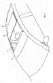
- Fig. 1 shows part of a vehicle, in particular an automobile, which comprises at least a roof opening 1 defined in a (stationary) roof part 2.
- a closure here in the form of a closure panel 3, is movable between a closed position (not shown) in which it closes the roof opening 1, and an open position (as shown) in which it opens the roof opening 1 and in which it is positioned at least partially above the roof part 2, here the fixed roof part adjoining the rear edge of the roof opening 1.
- a roof system (which is also known as a top slider roof) could comprise additional elements, such as for example a tiltable wind deflector positioned ahead of the roof opening 1, or further movable or stationary panels, for example in a position behind the panel 3 when it is in its closed position.
- the roof part behind the roof opening 1 is formed by a roof panel 3' which may be a stationary roof panel or a movable panel.
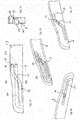
- Fig. 2 and 3 show the parts of an operating mechanism for closure panel 3 in order to move it between the closed and open positions.
- One of the longitudinal sides of closure panel 3 is shown in Fig. 3 , and it is noted that the same parts albeit in mirror image are present on the other longitudinal side of panel 3.
- the panel 3 comprises a glass or plastic transparent or metal non-transparent sheet supported on the longitudinal sides by a panel bracket fixed to sheet, for example by encapsulation material and/or any other means (not shown).
- a stationary guide rail 4 having several guide grooves in which parts of the operating mechanism are slidably guided.
- the guide rails 4 are straight or slightly curved in order to follow the curvature of the vehicle roof.
- the operating mechanism comprises a front device 5 to move the front side of closure panel 1 in vertical direction and a rear device 6 to move the rear side of closure panel 3 in vertical direction, i.e. up and down.
- both devices are also used to move closure panel 3 in longitudinal or horizontal direction, i.e. back and forth.
- the front and rear devices 5, 6 here each comprise a lever 7, 8 respectively as a panel support, the movements of which are controlled by a driving slide 9 guided in a groove in the respective guide rail 4 and driven by an electric motor 27 or the like through elongated drive elements, such as cables 28.
- both curve 12 and curve 13 have a depth that is more than half of the thickness of the body of driving slide 9, so that they will overlap each other when seen in a transverse cross-section. As a result they will intersect, resulting into a through hole 14 in the body of driving slide 9 at the point of intersection. This is, however, no problem as long as both cams 10, 11 are not present at the intersection at the same time.
- Figs. 3 , 5 and 6 show that cams 10, 11 do indeed not interfere.
- cam 11 is at the intersection, i.e. through hole 14, and in Fig. 5 , cam 10 has just passed through hole 14, while cam 11 is already a considerable distance from through hole 14.
- Fig. 4 also shows how both cams are formed on lever 8. It makes clear that the lower part of lever 8 is forked thereby forming legs 15, 16 straddling driving slide 9, such that cams 10, 11 point towards the inside of legs 15, 16. Of course, cams 10, 11 must not be aligned, but should be offset, as seen in side view, if they are stationary with respect to each other.
- Figs. 3 and 4 also show that cams 10, 11 are different in size and cross-section. Cam 10 is larger than cam 11 and has a non-circular cross-section, while cam 10 has a circular cross-section. This is however not necessary on behalf of the crossing curves 12, 13. The depth of curves 12, 13 may also be chosen at will, and therefore may be different or the same, whatever is best for guiding their cams 10, 11. Cams having a circular cross-section are preferred as they need less spacious curves.
- Figs. 7 - 17 show a second embodiment of the invention.
- a driving slide 9 now comprising a single guide curve 17 cooperating with two guide cams 18, 19.
- a locking or coupling curve 20 provided in the other wall of the body of driving slide 9, so that guide curve 17 and locking curve 20 face away from each other. They also intersect, resulting in a through hole 21, see for a comparative shape of through hole 21 Figs. 15 - 17 .
- Locking curve 20 is used to couple or uncouple driving slide 9 to or from locking lever 22 by means of a coupling cam 23.
- Locking lever 22 controls the longitudinal movement of lever 7 of front device 5.
- Figs. 7, 8 and 9 show that guide cam 18 or 19 and coupling cam 23 are never at through hole 21 at the same time, so that they do not interfere with each other.
- Figs. 14 - 17 show that guide curve 17 and locking curve 20 have a depth that extends almost the complete thickness of the body of driving slide 9, i.e. substantially more than half the thickness of the body of driving slide 9. Because a body part on both sides of each curve 17, 20 remain at the intersection, cams 18, 23 will continue to follow its curve when passing the intersection at through hole 21.
- the invention provides an operating mechanism for a roof system in which a slide may have a small thickness, while still including crossing curves, thus obtaining a small package in Y-direction.
- the cams will be supported well, due to their depth of engagement into their corresponding curves.
- Cams and pins may have all kinds of shapes and are not limited to the cross-sectional shapes shown in the drawings.
- the curve construction could also be used in other operating mechanisms, such as for tilt-sliding roofs, spoiler roofs and the like. Other movements of the closure panel could be effected if desired.
- the cams may be provided on other parts of the operating mechanism, either both on the same part or on different parts.
Landscapes
- Engineering & Computer Science (AREA)
- Mechanical Engineering (AREA)
- Lock And Its Accessories (AREA)
- Fittings On The Vehicle Exterior For Carrying Loads, And Devices For Holding Or Mounting Articles (AREA)
Abstract
Description
- The invention relates to a roof system for a vehicle according to the preamble of
claim 1. - Such roof system is known from the prior art. In this prior art roof system, the curves are provided in a wall of the body of the slide and the cams and curves are made such that both cams will stay in their curve when they cross the other curve. This is accomplished for example by making one curve deeper than the other and/or by providing one cam with another cross section than the other cam. The first measure solves the problem for one cam, but not completely for the other one. The second measure may cause problems in other areas, for example if a non-circular cam must move through a bend, the cross-section of the curve must be adapted.
- It is one of the objects of the present invention to provide a roof system in which these problems are solved or at least reduced.
- For this purpose, the curves are arranged in substantially parallel walls of the body of the slide that face away from each other.
- By providing the curves in opposite walls of the body of the slide that face away from each other, the cams will never be able to enter the other curve because they are on the other side of the body. Therefore, it is easy to use cams in the form of a cam having the same circular cross-section. No additional measures for such cams are required.
- The curves and body may have such depth that the curves overlap each other in depth direction of the body of the slide, such that the body will show a through hole at the position where the curves are crossing. Such through hole at the crossing will not interfere as long as the cams are not able to enter it. This is normally not a problem as the cams will not be able to move in a direction perpendicularly to the plane of the curves.
- Each curve may thus have a depth that is larger than half of the thickness of the body of the slide, which means that a relatively thin body for the slide may be used and therefore a small Y-package (in transverse direction of the roof system) can be obtained.
- In one embodiment, both cams may be provided on the support in the form of a lever, said lever being forked having two legs, one on each side of the slide and carrying one of the cams. In this way the lever of the support may cooperate with both sides of the slide body.
- In another embodiment, one cam may be provided on the support to move the support when the slide is driven, and the other cam may be provided on a locking member to lock the slide with respect to the guide rail.
- Other embodiments are of course conceivable.
- Further details and advantages of the invention will become more clear from the following description of embodiments of the roof system with reference to the drawings.
-
Fig. 1 is perspective view of a vehicle roof comprising an embodiment of a roof system according to the invention. -
Fig. 2 is a simplified exploded view of the roof system ofFig. 1 . -
Fig. 3 is a side view of detail III inFig. 2 on a larger scale and showing a part of the operating mechanism on one side of the roof system. -
Fig. 4 is a sectional view according to the line IV-IV on a larger scale. -
Fig. 5 and 6 are views similar to that ofFig. 4 , but showing the operating mechanism in different positions. -
Fig. 7, 8 and9 are views similar to that ofFig. 4 , but showing a second embodiment of the operating mechanism in three different positions. -
Fig. 10, 11 and 12 are sectional views according to the lines X, XI and XII, respectively, inFigs. 7 and 8 . -
Fig. 13 is a simplified side view of a part of a slide in the operating mechanism ofFig. 7 at the position of two crossing curves. -
Fig. 14 is a sectional view according to the line XIV-XIV inFig. 13 on a slightly larger scale. -
Figs. 15, 16 and 17 show the part of the slide ofFig. 13 in three different manners. -
Fig. 1 shows part of a vehicle, in particular an automobile, which comprises at least aroof opening 1 defined in a (stationary)roof part 2. A closure, here in the form of aclosure panel 3, is movable between a closed position (not shown) in which it closes the roof opening 1, and an open position (as shown) in which it opens the roof opening 1 and in which it is positioned at least partially above theroof part 2, here the fixed roof part adjoining the rear edge of the roof opening 1. - As is known per se such a roof system (which is also known as a top slider roof) could comprise additional elements, such as for example a tiltable wind deflector positioned ahead of the
roof opening 1, or further movable or stationary panels, for example in a position behind thepanel 3 when it is in its closed position. In fact, in the present embodiment, the roof part behind theroof opening 1 is formed by a roof panel 3' which may be a stationary roof panel or a movable panel. -
Fig. 2 and3 show the parts of an operating mechanism forclosure panel 3 in order to move it between the closed and open positions. One of the longitudinal sides ofclosure panel 3 is shown inFig. 3 , and it is noted that the same parts albeit in mirror image are present on the other longitudinal side ofpanel 3. Thepanel 3 comprises a glass or plastic transparent or metal non-transparent sheet supported on the longitudinal sides by a panel bracket fixed to sheet, for example by encapsulation material and/or any other means (not shown). At each longitudinal side edge of roof opening 1 there is provided on a frame 26 or other stationary part a stationary guide rail 4 having several guide grooves in which parts of the operating mechanism are slidably guided. The guide rails 4 are straight or slightly curved in order to follow the curvature of the vehicle roof. - To move
closure panel 3 in longitudinal (along the guide rail 4) and vertical (substantially perpendicular to the guide rail 4) directions, the operating mechanism comprises afront device 5 to move the front side ofclosure panel 1 in vertical direction and arear device 6 to move the rear side ofclosure panel 3 in vertical direction, i.e. up and down. Of course, both devices are also used to moveclosure panel 3 in longitudinal or horizontal direction, i.e. back and forth. The front andrear devices lever slide 9 guided in a groove in the respective guide rail 4 and driven by anelectric motor 27 or the like through elongated drive elements, such ascables 28. - The control of
levers slide 9 takes place by cam-curve connections, in the case oflever 8 ofrear device 6 bycams lever 8engaging guide curves driving slide 9. As is clear fromFig. 3 ,guide curves cams wrong guide curve guide curves slide 9. - As is shown in
Fig. 4 , bothcurve 12 andcurve 13 have a depth that is more than half of the thickness of the body of drivingslide 9, so that they will overlap each other when seen in a transverse cross-section. As a result they will intersect, resulting into a throughhole 14 in the body of drivingslide 9 at the point of intersection. This is, however, no problem as long as bothcams Figs. 3 ,5 and 6 show thatcams Fig. 3 ,cam 11 is at the intersection, i.e. throughhole 14, and inFig. 5 ,cam 10 has just passed throughhole 14, whilecam 11 is already a considerable distance from throughhole 14. -
Fig. 4 also shows how both cams are formed onlever 8. It makes clear that the lower part oflever 8 is forked thereby forminglegs 15, 16straddling driving slide 9, such that cams 10, 11 point towards the inside oflegs 15, 16. Of course,cams Figs. 3 and 4 also show thatcams Cam 10 is larger thancam 11 and has a non-circular cross-section, whilecam 10 has a circular cross-section. This is however not necessary on behalf of thecrossing curves curves cams -
Figs. 7 - 17 show a second embodiment of the invention. In this embodiment, there is again adriving slide 9 now comprising asingle guide curve 17 cooperating with twoguide cams coupling curve 20 provided in the other wall of the body of drivingslide 9, so thatguide curve 17 andlocking curve 20 face away from each other. They also intersect, resulting in athrough hole 21, see for a comparative shape of throughhole 21Figs. 15 - 17 .Locking curve 20 is used to couple oruncouple driving slide 9 to or from lockinglever 22 by means of acoupling cam 23.Locking lever 22 controls the longitudinal movement oflever 7 offront device 5. - When
coupling cam 23 is in horizontal curve portion 20' (inFig. 7 and 8 ), drivingslide 9 can move with respect to lockinglever 22, which is then locked with respect to guide rail 4 (by means oflocking cam 24 inrecess 25 in guide rail 4). When couplingcam 23 moves intoinclined curve portion 20" of lockingcurve 20, lockinglever 22 is locked with respect to drivingslide 9 and unlocked from guide rail 4 (lockingcam 24 is out of recess 25), so that bothslides Fig. 9 . -
Figs. 7, 8 and9 show that guidecam coupling cam 23 are never at throughhole 21 at the same time, so that they do not interfere with each other. -
Figs. 14 - 17 show that guidecurve 17 andlocking curve 20 have a depth that extends almost the complete thickness of the body of drivingslide 9, i.e. substantially more than half the thickness of the body of drivingslide 9. Because a body part on both sides of eachcurve cams hole 21. - From the foregoing it will be clear that the invention provides an operating mechanism for a roof system in which a slide may have a small thickness, while still including crossing curves, thus obtaining a small package in Y-direction. Despite the small package in Y-direction, the cams will be supported well, due to their depth of engagement into their corresponding curves.
- The invention is not limited to the embodiment shown in the drawings and described above, which may be varied in different manners within the scope of the invention. Features of different embodiment may be combined in other ways. Cams and pins may have all kinds of shapes and are not limited to the cross-sectional shapes shown in the drawings. The curve construction could also be used in other operating mechanisms, such as for tilt-sliding roofs, spoiler roofs and the like. Other movements of the closure panel could be effected if desired. The cams may be provided on other parts of the operating mechanism, either both on the same part or on different parts.
Claims (8)
- Roof system for a vehicle having a roof opening (1) in a roof part (2) thereof, comprising:
at least a closure (3) which is movable between a closed position in which it closes the roof opening and an open position in which it opens the roof opening, the closure being movable by an operating mechanism including at least a guide rail (4) extending in a longitudinal direction of the roof system, a closure support (8) and a slide (9) which is slidable in the guide rail and cooperates at least with the closure support, said slide (9) comprises a body and at least two curves (12, 13; 17, 20) provided in the body and each cooperating with at least a cam (10, 11; 19, 23), the cams being provided on at least the closure support (8) and the curves having such extent that they cross each other between their ends, characterized in that the curves (12, 13; 17, 20) are arranged in substantially parallel walls of the body of the slide (9) that face away from each other. - Roof system according to claim 1, wherein the curves (12, 13; 17, 20) and body of the slide (9) have such depth that the curves overlap each other in depth direction of the body of the slide, such that the body will show a through hole (14; 21) at the position where the curves are crossing.
- Roof system according to claim 2, wherein each curve (12, 13; 17, 20) has a depth that is larger than half of the thickness of the body of the slide (9).
- Roof system according to claim 1, 2 or 3, wherein both cams (10, 11) are provided on the support (8) in the form of a lever, said lever being forked having two legs (15, 16), one on each side of the slide and carrying one of the cams (10, 11) .
- Roof system according to claim 1, 2 or 3, wherein one cam (19) is provided on the support (8) to move the support when the slide (9) is driven, and the other cam (23) is provided on a locking member (22) to lock the slide (9) with respect to the guide rail (4).
- Roof system according to any of the preceding claims, wherein the cams (10, 11; 19, 23) are each in the form of a cam having a circular cross-section.
- Roof system according to claim 6, wherein the cams (19, 23) have the same cross-section.
- Roof system according to any of claims 1 - 5, wherein the cams (10, 11; 19, 23) have different cross-sectional shapes and/or dimensions.
Priority Applications (3)
| Application Number | Priority Date | Filing Date | Title |
|---|---|---|---|
| EP19203508.7A EP3808582B1 (en) | 2019-10-16 | 2019-10-16 | Roof system for a vehicle |
| CN202010999390.3A CN112659863B (en) | 2019-10-16 | 2020-09-22 | Roof systems for vehicles |
| US17/069,474 US11655660B2 (en) | 2019-10-16 | 2020-10-13 | Roof system for a vehicle |
Applications Claiming Priority (1)
| Application Number | Priority Date | Filing Date | Title |
|---|---|---|---|
| EP19203508.7A EP3808582B1 (en) | 2019-10-16 | 2019-10-16 | Roof system for a vehicle |
Publications (2)
| Publication Number | Publication Date |
|---|---|
| EP3808582A1 true EP3808582A1 (en) | 2021-04-21 |
| EP3808582B1 EP3808582B1 (en) | 2023-06-07 |
Family
ID=68289885
Family Applications (1)
| Application Number | Title | Priority Date | Filing Date |
|---|---|---|---|
| EP19203508.7A Active EP3808582B1 (en) | 2019-10-16 | 2019-10-16 | Roof system for a vehicle |
Country Status (3)
| Country | Link |
|---|---|
| US (1) | US11655660B2 (en) |
| EP (1) | EP3808582B1 (en) |
| CN (1) | CN112659863B (en) |
Families Citing this family (1)
| Publication number | Priority date | Publication date | Assignee | Title |
|---|---|---|---|---|
| CN219467506U (en) * | 2022-10-11 | 2023-08-04 | 福州明芳汽车部件工业有限公司 | sunroof device |
Citations (5)
| Publication number | Priority date | Publication date | Assignee | Title |
|---|---|---|---|---|
| DE4424509A1 (en) * | 1993-07-13 | 1995-01-19 | Aisin Seiki | Sun roof device for a vehicle |
| GB2320055A (en) * | 1996-08-30 | 1998-06-10 | Ohi Seisakusho Co Ltd | Sliding shoe for sun roof device |
| DE102006050851A1 (en) * | 2006-10-27 | 2008-04-30 | Webasto Ag | Double-sided slotted cover lifting guide structure for controlling lifting movement of cover, has slotted guide mounted on side of lifting cover support |
| DE102007003354A1 (en) * | 2007-01-17 | 2008-07-31 | Webasto Ag | Vehicle roof has roof part which closes or partially releases roof opening in roof of vehicle, and roof part moves into exhaust position with upward formed rear edge |
| DE102014014170A1 (en) * | 2014-09-24 | 2016-03-24 | Webasto SE | Openable vehicle roof with an adjustable lid |
Family Cites Families (5)
| Publication number | Priority date | Publication date | Assignee | Title |
|---|---|---|---|---|
| EP3034343B1 (en) * | 2014-12-17 | 2020-05-13 | Inalfa Roof Systems Group B.V. | Roof system for a vehicle |
| DE102015201587A1 (en) * | 2015-01-29 | 2016-08-04 | Bos Gmbh & Co. Kg | Drive system for a movable roof part of a roof module of a motor vehicle |
| EP3106331A1 (en) * | 2015-06-15 | 2016-12-21 | Webasto SE | Sliding roof device for motor vehicle |
| US10239391B1 (en) * | 2017-09-26 | 2019-03-26 | AISIN Technical Center of America, Inc. | Sliding apparatus for sunroof of an automobile |
| CN109367373B (en) * | 2018-12-13 | 2024-06-21 | 江苏德福来汽车部件有限公司 | Skylight machinery group |
-
2019
- 2019-10-16 EP EP19203508.7A patent/EP3808582B1/en active Active
-
2020
- 2020-09-22 CN CN202010999390.3A patent/CN112659863B/en active Active
- 2020-10-13 US US17/069,474 patent/US11655660B2/en active Active
Patent Citations (5)
| Publication number | Priority date | Publication date | Assignee | Title |
|---|---|---|---|---|
| DE4424509A1 (en) * | 1993-07-13 | 1995-01-19 | Aisin Seiki | Sun roof device for a vehicle |
| GB2320055A (en) * | 1996-08-30 | 1998-06-10 | Ohi Seisakusho Co Ltd | Sliding shoe for sun roof device |
| DE102006050851A1 (en) * | 2006-10-27 | 2008-04-30 | Webasto Ag | Double-sided slotted cover lifting guide structure for controlling lifting movement of cover, has slotted guide mounted on side of lifting cover support |
| DE102007003354A1 (en) * | 2007-01-17 | 2008-07-31 | Webasto Ag | Vehicle roof has roof part which closes or partially releases roof opening in roof of vehicle, and roof part moves into exhaust position with upward formed rear edge |
| DE102014014170A1 (en) * | 2014-09-24 | 2016-03-24 | Webasto SE | Openable vehicle roof with an adjustable lid |
Also Published As
| Publication number | Publication date |
|---|---|
| US11655660B2 (en) | 2023-05-23 |
| EP3808582B1 (en) | 2023-06-07 |
| CN112659863A (en) | 2021-04-16 |
| US20210115719A1 (en) | 2021-04-22 |
| CN112659863B (en) | 2025-09-23 |
Similar Documents
| Publication | Publication Date | Title |
|---|---|---|
| EP2078630B1 (en) | Open roof construction for a vehicle | |
| EP3832060B1 (en) | Power slide window | |
| EP2955042B1 (en) | Vehicle sunroof device | |
| US11331988B2 (en) | Roof system for a vehicle | |
| JP4164112B2 (en) | Stopper structure in sunroof device | |
| US20160200183A1 (en) | Arrangement for a Vehicle Roof with a Cover | |
| EP3808582B1 (en) | Roof system for a vehicle | |
| EP3832061B1 (en) | Power slide window | |
| US20050023868A1 (en) | Motor vehicle roof | |
| US11273693B2 (en) | Roof system for a vehicle | |
| KR20130139168A (en) | Car Open Loop System | |
| EP3106331A1 (en) | Sliding roof device for motor vehicle | |
| US11541732B1 (en) | Vehicle door assembly | |
| EP3661778B1 (en) | Open roof construction for a vehicle | |
| JP7752751B2 (en) | Device for vehicle roof and vehicle roof | |
| US11607937B2 (en) | Roof system for a vehicle | |
| US7367614B2 (en) | Multi-panel sunshade device | |
| US20050001447A1 (en) | Actuating device for open/close member of vehicle | |
| US20240408945A1 (en) | Arrangement for moving a cover for a vehicle roof, and vehicle roof | |
| CN118144520A (en) | Roof systems for vehicles |
Legal Events
| Date | Code | Title | Description |
|---|---|---|---|
| PUAI | Public reference made under article 153(3) epc to a published international application that has entered the european phase |
Free format text: ORIGINAL CODE: 0009012 |
|
| STAA | Information on the status of an ep patent application or granted ep patent |
Free format text: STATUS: THE APPLICATION HAS BEEN PUBLISHED |
|
| AK | Designated contracting states |
Kind code of ref document: A1 Designated state(s): AL AT BE BG CH CY CZ DE DK EE ES FI FR GB GR HR HU IE IS IT LI LT LU LV MC MK MT NL NO PL PT RO RS SE SI SK SM TR |
|
| AX | Request for extension of the european patent |
Extension state: BA ME |
|
| STAA | Information on the status of an ep patent application or granted ep patent |
Free format text: STATUS: REQUEST FOR EXAMINATION WAS MADE |
|
| 17P | Request for examination filed |
Effective date: 20210928 |
|
| RBV | Designated contracting states (corrected) |
Designated state(s): AL AT BE BG CH CY CZ DE DK EE ES FI FR GB GR HR HU IE IS IT LI LT LU LV MC MK MT NL NO PL PT RO RS SE SI SK SM TR |
|
| GRAP | Despatch of communication of intention to grant a patent |
Free format text: ORIGINAL CODE: EPIDOSNIGR1 |
|
| STAA | Information on the status of an ep patent application or granted ep patent |
Free format text: STATUS: GRANT OF PATENT IS INTENDED |
|
| INTG | Intention to grant announced |
Effective date: 20221117 |
|
| GRAS | Grant fee paid |
Free format text: ORIGINAL CODE: EPIDOSNIGR3 |
|
| GRAA | (expected) grant |
Free format text: ORIGINAL CODE: 0009210 |
|
| STAA | Information on the status of an ep patent application or granted ep patent |
Free format text: STATUS: THE PATENT HAS BEEN GRANTED |
|
| AK | Designated contracting states |
Kind code of ref document: B1 Designated state(s): AL AT BE BG CH CY CZ DE DK EE ES FI FR GB GR HR HU IE IS IT LI LT LU LV MC MK MT NL NO PL PT RO RS SE SI SK SM TR |
|
| REG | Reference to a national code |
Ref country code: GB Ref legal event code: FG4D |
|
| REG | Reference to a national code |
Ref country code: CH Ref legal event code: EP Ref country code: AT Ref legal event code: REF Ref document number: 1573980 Country of ref document: AT Kind code of ref document: T Effective date: 20230615 |
|
| REG | Reference to a national code |
Ref country code: DE Ref legal event code: R096 Ref document number: 602019029904 Country of ref document: DE |
|
| REG | Reference to a national code |
Ref country code: LT Ref legal event code: MG9D |
|
| REG | Reference to a national code |
Ref country code: NL Ref legal event code: MP Effective date: 20230607 |
|
| PG25 | Lapsed in a contracting state [announced via postgrant information from national office to epo] |
Ref country code: SE Free format text: LAPSE BECAUSE OF FAILURE TO SUBMIT A TRANSLATION OF THE DESCRIPTION OR TO PAY THE FEE WITHIN THE PRESCRIBED TIME-LIMIT Effective date: 20230607 Ref country code: NO Free format text: LAPSE BECAUSE OF FAILURE TO SUBMIT A TRANSLATION OF THE DESCRIPTION OR TO PAY THE FEE WITHIN THE PRESCRIBED TIME-LIMIT Effective date: 20230907 Ref country code: ES Free format text: LAPSE BECAUSE OF FAILURE TO SUBMIT A TRANSLATION OF THE DESCRIPTION OR TO PAY THE FEE WITHIN THE PRESCRIBED TIME-LIMIT Effective date: 20230607 |
|
| REG | Reference to a national code |
Ref country code: AT Ref legal event code: MK05 Ref document number: 1573980 Country of ref document: AT Kind code of ref document: T Effective date: 20230607 |
|
| PG25 | Lapsed in a contracting state [announced via postgrant information from national office to epo] |
Ref country code: RS Free format text: LAPSE BECAUSE OF FAILURE TO SUBMIT A TRANSLATION OF THE DESCRIPTION OR TO PAY THE FEE WITHIN THE PRESCRIBED TIME-LIMIT Effective date: 20230607 Ref country code: NL Free format text: LAPSE BECAUSE OF FAILURE TO SUBMIT A TRANSLATION OF THE DESCRIPTION OR TO PAY THE FEE WITHIN THE PRESCRIBED TIME-LIMIT Effective date: 20230607 Ref country code: LV Free format text: LAPSE BECAUSE OF FAILURE TO SUBMIT A TRANSLATION OF THE DESCRIPTION OR TO PAY THE FEE WITHIN THE PRESCRIBED TIME-LIMIT Effective date: 20230607 Ref country code: LT Free format text: LAPSE BECAUSE OF FAILURE TO SUBMIT A TRANSLATION OF THE DESCRIPTION OR TO PAY THE FEE WITHIN THE PRESCRIBED TIME-LIMIT Effective date: 20230607 Ref country code: HR Free format text: LAPSE BECAUSE OF FAILURE TO SUBMIT A TRANSLATION OF THE DESCRIPTION OR TO PAY THE FEE WITHIN THE PRESCRIBED TIME-LIMIT Effective date: 20230607 Ref country code: GR Free format text: LAPSE BECAUSE OF FAILURE TO SUBMIT A TRANSLATION OF THE DESCRIPTION OR TO PAY THE FEE WITHIN THE PRESCRIBED TIME-LIMIT Effective date: 20230908 |
|
| PG25 | Lapsed in a contracting state [announced via postgrant information from national office to epo] |
Ref country code: FI Free format text: LAPSE BECAUSE OF FAILURE TO SUBMIT A TRANSLATION OF THE DESCRIPTION OR TO PAY THE FEE WITHIN THE PRESCRIBED TIME-LIMIT Effective date: 20230607 |
|
| PG25 | Lapsed in a contracting state [announced via postgrant information from national office to epo] |
Ref country code: SK Free format text: LAPSE BECAUSE OF FAILURE TO SUBMIT A TRANSLATION OF THE DESCRIPTION OR TO PAY THE FEE WITHIN THE PRESCRIBED TIME-LIMIT Effective date: 20230607 |
|
| PG25 | Lapsed in a contracting state [announced via postgrant information from national office to epo] |
Ref country code: IS Free format text: LAPSE BECAUSE OF FAILURE TO SUBMIT A TRANSLATION OF THE DESCRIPTION OR TO PAY THE FEE WITHIN THE PRESCRIBED TIME-LIMIT Effective date: 20231007 |
|
| PG25 | Lapsed in a contracting state [announced via postgrant information from national office to epo] |
Ref country code: SM Free format text: LAPSE BECAUSE OF FAILURE TO SUBMIT A TRANSLATION OF THE DESCRIPTION OR TO PAY THE FEE WITHIN THE PRESCRIBED TIME-LIMIT Effective date: 20230607 Ref country code: SK Free format text: LAPSE BECAUSE OF FAILURE TO SUBMIT A TRANSLATION OF THE DESCRIPTION OR TO PAY THE FEE WITHIN THE PRESCRIBED TIME-LIMIT Effective date: 20230607 Ref country code: RO Free format text: LAPSE BECAUSE OF FAILURE TO SUBMIT A TRANSLATION OF THE DESCRIPTION OR TO PAY THE FEE WITHIN THE PRESCRIBED TIME-LIMIT Effective date: 20230607 Ref country code: PT Free format text: LAPSE BECAUSE OF FAILURE TO SUBMIT A TRANSLATION OF THE DESCRIPTION OR TO PAY THE FEE WITHIN THE PRESCRIBED TIME-LIMIT Effective date: 20231009 Ref country code: IS Free format text: LAPSE BECAUSE OF FAILURE TO SUBMIT A TRANSLATION OF THE DESCRIPTION OR TO PAY THE FEE WITHIN THE PRESCRIBED TIME-LIMIT Effective date: 20231007 Ref country code: EE Free format text: LAPSE BECAUSE OF FAILURE TO SUBMIT A TRANSLATION OF THE DESCRIPTION OR TO PAY THE FEE WITHIN THE PRESCRIBED TIME-LIMIT Effective date: 20230607 Ref country code: CZ Free format text: LAPSE BECAUSE OF FAILURE TO SUBMIT A TRANSLATION OF THE DESCRIPTION OR TO PAY THE FEE WITHIN THE PRESCRIBED TIME-LIMIT Effective date: 20230607 Ref country code: AT Free format text: LAPSE BECAUSE OF FAILURE TO SUBMIT A TRANSLATION OF THE DESCRIPTION OR TO PAY THE FEE WITHIN THE PRESCRIBED TIME-LIMIT Effective date: 20230607 |
|
| PG25 | Lapsed in a contracting state [announced via postgrant information from national office to epo] |
Ref country code: PL Free format text: LAPSE BECAUSE OF FAILURE TO SUBMIT A TRANSLATION OF THE DESCRIPTION OR TO PAY THE FEE WITHIN THE PRESCRIBED TIME-LIMIT Effective date: 20230607 |
|
| REG | Reference to a national code |
Ref country code: DE Ref legal event code: R097 Ref document number: 602019029904 Country of ref document: DE |
|
| PLBE | No opposition filed within time limit |
Free format text: ORIGINAL CODE: 0009261 |
|
| STAA | Information on the status of an ep patent application or granted ep patent |
Free format text: STATUS: NO OPPOSITION FILED WITHIN TIME LIMIT |
|
| PG25 | Lapsed in a contracting state [announced via postgrant information from national office to epo] |
Ref country code: DK Free format text: LAPSE BECAUSE OF FAILURE TO SUBMIT A TRANSLATION OF THE DESCRIPTION OR TO PAY THE FEE WITHIN THE PRESCRIBED TIME-LIMIT Effective date: 20230607 |
|
| PG25 | Lapsed in a contracting state [announced via postgrant information from national office to epo] |
Ref country code: SI Free format text: LAPSE BECAUSE OF FAILURE TO SUBMIT A TRANSLATION OF THE DESCRIPTION OR TO PAY THE FEE WITHIN THE PRESCRIBED TIME-LIMIT Effective date: 20230607 |
|
| 26N | No opposition filed |
Effective date: 20240308 |
|
| PG25 | Lapsed in a contracting state [announced via postgrant information from national office to epo] |
Ref country code: SI Free format text: LAPSE BECAUSE OF FAILURE TO SUBMIT A TRANSLATION OF THE DESCRIPTION OR TO PAY THE FEE WITHIN THE PRESCRIBED TIME-LIMIT Effective date: 20230607 Ref country code: IT Free format text: LAPSE BECAUSE OF FAILURE TO SUBMIT A TRANSLATION OF THE DESCRIPTION OR TO PAY THE FEE WITHIN THE PRESCRIBED TIME-LIMIT Effective date: 20230607 Ref country code: MC Free format text: LAPSE BECAUSE OF FAILURE TO SUBMIT A TRANSLATION OF THE DESCRIPTION OR TO PAY THE FEE WITHIN THE PRESCRIBED TIME-LIMIT Effective date: 20230607 |
|
| REG | Reference to a national code |
Ref country code: CH Ref legal event code: PL |
|
| REG | Reference to a national code |
Ref country code: BE Ref legal event code: MM Effective date: 20231031 |
|
| PG25 | Lapsed in a contracting state [announced via postgrant information from national office to epo] |
Ref country code: LU Free format text: LAPSE BECAUSE OF NON-PAYMENT OF DUE FEES Effective date: 20231016 |
|
| GBPC | Gb: european patent ceased through non-payment of renewal fee |
Effective date: 20231016 |
|
| PG25 | Lapsed in a contracting state [announced via postgrant information from national office to epo] |
Ref country code: LU Free format text: LAPSE BECAUSE OF NON-PAYMENT OF DUE FEES Effective date: 20231016 |
|
| PG25 | Lapsed in a contracting state [announced via postgrant information from national office to epo] |
Ref country code: GB Free format text: LAPSE BECAUSE OF NON-PAYMENT OF DUE FEES Effective date: 20231016 |
|
| PG25 | Lapsed in a contracting state [announced via postgrant information from national office to epo] |
Ref country code: CH Free format text: LAPSE BECAUSE OF NON-PAYMENT OF DUE FEES Effective date: 20231031 |
|
| PG25 | Lapsed in a contracting state [announced via postgrant information from national office to epo] |
Ref country code: GB Free format text: LAPSE BECAUSE OF NON-PAYMENT OF DUE FEES Effective date: 20231016 Ref country code: CH Free format text: LAPSE BECAUSE OF NON-PAYMENT OF DUE FEES Effective date: 20231031 |
|
| PG25 | Lapsed in a contracting state [announced via postgrant information from national office to epo] |
Ref country code: BE Free format text: LAPSE BECAUSE OF NON-PAYMENT OF DUE FEES Effective date: 20231031 |
|
| PG25 | Lapsed in a contracting state [announced via postgrant information from national office to epo] |
Ref country code: IE Free format text: LAPSE BECAUSE OF NON-PAYMENT OF DUE FEES Effective date: 20231016 |
|
| PG25 | Lapsed in a contracting state [announced via postgrant information from national office to epo] |
Ref country code: IE Free format text: LAPSE BECAUSE OF NON-PAYMENT OF DUE FEES Effective date: 20231016 |
|
| PG25 | Lapsed in a contracting state [announced via postgrant information from national office to epo] |
Ref country code: BG Free format text: LAPSE BECAUSE OF FAILURE TO SUBMIT A TRANSLATION OF THE DESCRIPTION OR TO PAY THE FEE WITHIN THE PRESCRIBED TIME-LIMIT Effective date: 20230607 |
|
| PG25 | Lapsed in a contracting state [announced via postgrant information from national office to epo] |
Ref country code: BG Free format text: LAPSE BECAUSE OF FAILURE TO SUBMIT A TRANSLATION OF THE DESCRIPTION OR TO PAY THE FEE WITHIN THE PRESCRIBED TIME-LIMIT Effective date: 20230607 |
|
| PG25 | Lapsed in a contracting state [announced via postgrant information from national office to epo] |
Ref country code: CY Free format text: LAPSE BECAUSE OF FAILURE TO SUBMIT A TRANSLATION OF THE DESCRIPTION OR TO PAY THE FEE WITHIN THE PRESCRIBED TIME-LIMIT; INVALID AB INITIO Effective date: 20191016 |
|
| PG25 | Lapsed in a contracting state [announced via postgrant information from national office to epo] |
Ref country code: HU Free format text: LAPSE BECAUSE OF FAILURE TO SUBMIT A TRANSLATION OF THE DESCRIPTION OR TO PAY THE FEE WITHIN THE PRESCRIBED TIME-LIMIT; INVALID AB INITIO Effective date: 20191016 |
|
| PG25 | Lapsed in a contracting state [announced via postgrant information from national office to epo] |
Ref country code: TR Free format text: LAPSE BECAUSE OF FAILURE TO SUBMIT A TRANSLATION OF THE DESCRIPTION OR TO PAY THE FEE WITHIN THE PRESCRIBED TIME-LIMIT Effective date: 20230607 |
|
| PGFP | Annual fee paid to national office [announced via postgrant information from national office to epo] |
Ref country code: DE Payment date: 20251029 Year of fee payment: 7 |
|
| PGFP | Annual fee paid to national office [announced via postgrant information from national office to epo] |
Ref country code: FR Payment date: 20251027 Year of fee payment: 7 |