EP3808169B1 - A pile-covering hood - Google Patents
A pile-covering hood Download PDFInfo
- Publication number
- EP3808169B1 EP3808169B1 EP20201129.2A EP20201129A EP3808169B1 EP 3808169 B1 EP3808169 B1 EP 3808169B1 EP 20201129 A EP20201129 A EP 20201129A EP 3808169 B1 EP3808169 B1 EP 3808169B1
- Authority
- EP
- European Patent Office
- Prior art keywords
- cover
- pole
- shaped
- locking element
- cover cap
- Prior art date
- Legal status (The legal status is an assumption and is not a legal conclusion. Google has not performed a legal analysis and makes no representation as to the accuracy of the status listed.)
- Active
Links
Images

Classifications
-
- A—HUMAN NECESSITIES
- A01—AGRICULTURE; FORESTRY; ANIMAL HUSBANDRY; HUNTING; TRAPPING; FISHING
- A01G—HORTICULTURE; CULTIVATION OF VEGETABLES, FLOWERS, RICE, FRUIT, VINES, HOPS OR SEAWEED; FORESTRY; WATERING
- A01G17/00—Cultivation of hops, vines, fruit trees, or like trees
- A01G17/04—Supports for hops, vines, or trees
- A01G17/06—Trellis-work
-
- A—HUMAN NECESSITIES
- A01—AGRICULTURE; FORESTRY; ANIMAL HUSBANDRY; HUNTING; TRAPPING; FISHING
- A01G—HORTICULTURE; CULTIVATION OF VEGETABLES, FLOWERS, RICE, FRUIT, VINES, HOPS OR SEAWEED; FORESTRY; WATERING
- A01G13/00—Protection of plants
- A01G13/20—Protective coverings for plants
- A01G13/21—Protective coverings for plants providing overhead protection, i.e. canopies
-
- E—FIXED CONSTRUCTIONS
- E04—BUILDING
- E04H—BUILDINGS OR LIKE STRUCTURES FOR PARTICULAR PURPOSES; SWIMMING OR SPLASH BATHS OR POOLS; MASTS; FENCING; TENTS OR CANOPIES, IN GENERAL
- E04H17/00—Fencing, e.g. fences, enclosures, corrals
- E04H17/006—Caps or covers for posts
Definitions
- the present invention is applicable to the agricultural sector and in particular to crop equipment.
- the present invention relates to crop covers.
- the structure of such covers comprises a series of poles connected together by steel wires and ropes, held in tension by special anchors fixed in the ground, on which protective nets and sheets are installed, in order to substantially form a roof to protect the crop.
- caps are inserted on the top of the latter.
- pole-cover caps are press-fitted onto the upper ends of the poles to which they adhere, thus avoiding loosening. In some instances, as a precaution, it is provided to insert an additional screw tightening to permanently secure the cap to the pole.
- pole-cover caps comprise grooves for the passage of wires and ropes, and a series of locking elements adapted to couple the components of the cover to the structure.
- the locking elements consist of a set of screw elements, metal or plastic washers, and nuts, which are generally coupled to a threaded screw associated with the cap.
- the plastic washers used in the known devices can be co-moulded with metal elements.
- the installation of the cover structure would be simplified if the ridge wire (longitudinal wire) were initially only partially fixed to the pole-cover cap, and following the installation of all the components of the cover, the wire could be tensioned and permanently fixed to the cap.
- the ridge wire is completely locked to the pole-cover cap, and following the completion of the installation of the cover, the locking elements are loosened to allow the tensioning of the wire and the consequent definitive locking.
- the ridge wire can only be attached to the pole-cover cap when all the cover components have been assembled.
- problems arise related to the stability of the cover during installation.
- pole-cover caps which comprise a snap plug which is inserted into the shaped body. Such plug creates a pressure on the ridge wire so as to lock it during the installation of the structure.
- a cap provided with a snap plug does not allow an adjustable pressure to be exerted on the ridge wire. Consequently, it is not possible to partially fix the wire to the cap to allow the installation of the entire structure and only then put the wire in tension and thus definitively lock it.
- pole-cover caps described in patent documents EP2353370 A1 and CN 206707403 U are also known, which have a fixing system which provides for screwing on a threaded screw.
- the object of the present invention is to provide a pole-cover cap according to claim 1 which allows at least partially overcoming the drawbacks highlighted above.
- an object of the present invention is to provide a pole-cover cap which can ensure an adequate fixing of the components of a crop cover (wires, ropes, nets and sheets) to a pole structure.
- a further object of the present invention is to provide a pole-cover cap in which the fixing of the cover elements to the structure is simplified with respect to the locking systems present in the prior art.
- an object of the present invention is to provide a pole-cover cap which allows a partial fixing of the ridge wire during the installation of the structure.
- a further object of the present invention is to provide a pole-cover cap in which the fixing elements allow an adjustable pressure to be exerted on the ridge wire.
- Another object of the present invention is to provide a pole-cover cap in which the locking system is easily reversible, so as to be able to unlock the cover elements when necessary.
- the pole-cover cap of the invention which can be associated with the head of cover poles, comprises a hollow body and a fixing assembly of a cover.
- such fixing assembly comprises a plurality of locking elements coupled to each other and each dedicated to the fixing to the pole-cover cap of corresponding components of the cover.
- locking elements is comprised a first locking element capable of fixing a ridge wire to the cap, i.e., the wire which longitudinally joins the poles.
- the shaped body comprises at least one groove to allow the passage of the aforementioned ridge wire on the pole-cover cap.
- the shaped body comprises a recess obtained at the top thereof and intersecting the aforementioned groove.
- Such recess is shaped to accommodate therein at least a portion of the first locking element so that the latter compresses the ridge wire on the recess.
- the side surface of the first locking element has a first shaping and the corresponding inner surface of the recess has a second shaping. Furthermore, such shapings are obtained so as to allow the coupling of the first locking element in the recess by rotation.
- the pole-cover cap of the invention thus allows to ensure an adequate fixing of the cover components to the structure.
- the coupling between the first locking element and the shaped body of the cap is such as to simplify the fixing operations with respect to the known systems.
- the coupling between the first locking element and the shaped body occurs by rotation.
- this allows to adjust the pressure exerted by the first locking element on the ridge wire, depending on the rotation angle impressed.
- said coupling by rotation allows a partial fixing of the ridge wire to the pole-cover cap. This allows to install all the components of the cover without incurring structural problems and then correctly tension the ridge wire before definitively fixing it to the cap.
- the coupling by rotation operation is easily reversible, allowing to meet the need to decouple the first locking element from the pole-cover cap.
- a pole-cover cap 1 which can be associated with the head of crop cover support poles. It comprises a hollow body 3 adapted to accommodate the head of the respective pole in the cavity thereof. It further comprises a fixing assembly 4 of the cover.
- the fixing assembly 4 comprises a plurality of locking elements 6 coupled to each other and each of them dedicated to fixing corresponding components of the cover.
- locking elements 6 are typically, but not necessarily, screw elements such as washers, nuts and screws.
- the components of the cover are generally wires, ropes (longitudinal and transverse to the structure of the cover), protective nets and/or sheets.
- each locking element is dedicated to fixing multiple components of the cover or where multiple locking elements are necessary to fix a single component.
- a first locking element 7 capable of fixing a ridge wire to the pole-cover cap 1.
- the first locking element 7 is a washer. Obviously, such aspect should not be considered limiting for different embodiments of the first locking element.
- the shaped body 3 comprises at the top thereof a groove 9 for the passage of the ridge wire on the cap 1.
- such shaped body 3 comprises an additional groove 10 for the passage of ropes transverse to the ridge wire.
- the shaped body may comprise multiple grooves or only one.
- the shaped body 3 also comprises a recess 12, obtained at the top thereof, intersecting the grooves 9 and 10 and shaped to accommodate therein a portion of the first locking element 7 so as to compress the ridge wire in the recess 12 itself.
- the side surface 14 of the first locking element 7 has a first shaping 15 and the corresponding inner surface 17 of the recess 12 has a second shaping 18 shaped to couple with the first shaping 15.
- the shapings 15 and 18 are such as to allow the mutual coupling thereof by rotation of the first locking element 7 in the recess 12, and consequently, to couple the first locking element 7 to the cap 1.
- the pole-cover cap 1 of the invention thus allows to ensure an adequate fixing of the cover components to the structure.
- the coupling by rotation of the first locking element 7 to the shaped body 3 advantageously allows to simplify the operations of fixing the ridge wire to the poles with respect to the known systems.
- the same coupling by rotation allows the pressure exerted on the ridge wire to be adjusted.
- a more or less intense pressure is exerted on the ridge wire.
- the possibility of adjusting the pressure exerted on the ridge wire allows to obtain a partial fixing of the wire to the cap 1 of the invention. Consequently, the pole-cover cap 1 of the invention allows to first install the cover with a first tensioning of the ridge wire and without incurring structural problems. At the end of the installation of all the components, the cap 1 of the invention allows to proceed with the definitive tensioning and fixing of the ridge wire without in any way affecting the other components of the cover.
- the coupling between the first locking element 7 and the shaped body 3 is easily reversible, simplifying any disassembly of the cover.
- the first shaping 15 comprises a substantially wedge-shaped protrusion 20, while the second shaping 18 comprises a substantially counter-wedge-shaped groove 21 adapted to accommodate the wedge-shaped protrusion 20.
- the manufacture of the first and the second shaping is a feature which should not be understood in a limiting sense for the present invention.
- the second shaping comprises a substantially wedge-shaped protrusion and the first shaping comprises a substantially counter-wedge-shaped groove adapted to accommodate such protrusion.
- the first shaping comprises a first thread while the second shaping comprises a second thread counter-shaped on the first to allow the screwing of the first locking element in the recess.
- the two shapings are such as to allow a bayonet-type engagement of the first locking element in the recess.
- the first locking element 7 has a through hole 25 to allow the passage of a junction group 26 of the other locking elements 6 forming the fixing assembly 4.
- the presence of a through hole 25 allows an independent coupling of the other locking elements 6 with respect to the first element 7.
- the shaped body 3 comprises a hole 28 on the side surface 29 thereof shaped to be struck by a fixing screw (not represented herein) of the pole-cover cap 1 to the pole head.
- the use of a fixing screw allows a more stable coupling of the cap 1 to the top of the poles.
- the coupling is interlocking or where there are multiple holes to accommodate multiple fixing screws.
- the object of the invention is also a crop cover comprising:
- pole-cover cap of the invention achieves all the intended objects.
- the pole-cover cap of the invention allows an adequate fixing of the components of a crop cover to a pole structure.
- the cap of the invention allows for a simplified fixing with respect to the locking systems present in the prior art.
- the pole-cover cap of the invention allows a partial fixing of the ridge wire during the assembly of the cover.
- the fixing elements of the invention allow an adjustable pressure to be exerted on the ridge wire, further simplifying the aforementioned assembly.
Landscapes
- Life Sciences & Earth Sciences (AREA)
- Environmental Sciences (AREA)
- Health & Medical Sciences (AREA)
- General Health & Medical Sciences (AREA)
- Toxicology (AREA)
- Botany (AREA)
- Catching Or Destruction (AREA)
- Closures For Containers (AREA)
- Suspension Of Electric Lines Or Cables (AREA)
Description
- The present invention is applicable to the agricultural sector and in particular to crop equipment.
- In more detail, the present invention relates to crop covers.
- In the agricultural sector there is often a need to provide crop cover systems to protect the crops from atmospheric agents.
- The structure of such covers comprises a series of poles connected together by steel wires and ropes, held in tension by special anchors fixed in the ground, on which protective nets and sheets are installed, in order to substantially form a roof to protect the crop.
- To allow a proper fixing of wires and ropes of the structure and to protect the nets and sheets from possible damage caused by the rough surfaces of the poles, generally in concrete, caps are inserted on the top of the latter.
- These pole-cover caps are press-fitted onto the upper ends of the poles to which they adhere, thus avoiding loosening. In some instances, as a precaution, it is provided to insert an additional screw tightening to permanently secure the cap to the pole.
- The most well-known type of pole-cover caps comprise grooves for the passage of wires and ropes, and a series of locking elements adapted to couple the components of the cover to the structure.
- Typically, the locking elements consist of a set of screw elements, metal or plastic washers, and nuts, which are generally coupled to a threaded screw associated with the cap.
- However, this fixing system is complex, as the number of screw elements necessary to secure the longitudinal wires, the transverse ropes and the net to the cap is very high.
- To reduce the number of elements required for the locking, the plastic washers used in the known devices can be co-moulded with metal elements.
- However, the decrease in the elements in use due to the co-moulding of the washers is not such as to lead to a significant simplification of the assembly of the cover.
- In particular, the installation of the cover structure would be simplified if the ridge wire (longitudinal wire) were initially only partially fixed to the pole-cover cap, and following the installation of all the components of the cover, the wire could be tensioned and permanently fixed to the cap.
- However, this procedure is not applicable using the pole-cover caps described heretofore.
- Usually, therefore, the ridge wire is completely locked to the pole-cover cap, and following the completion of the installation of the cover, the locking elements are loosened to allow the tensioning of the wire and the consequent definitive locking.
- However, the loosening of the locking elements after installation entails a large burden in terms of time and operational complexity. Moreover, the other components of the cover may lose their optimal arrangement.
- Alternatively, the ridge wire can only be attached to the pole-cover cap when all the cover components have been assembled. However, following this installation procedure problems arise related to the stability of the cover during installation.
- According to the state of the art, pole-cover caps are also known which comprise a snap plug which is inserted into the shaped body. Such plug creates a pressure on the ridge wire so as to lock it during the installation of the structure.
- However, the use of a snap mechanism makes the removal of the plug very difficult, thus complicating any replacement of the cover elements.
- In addition, a cap provided with a snap plug does not allow an adjustable pressure to be exerted on the ridge wire. Consequently, it is not possible to partially fix the wire to the cap to allow the installation of the entire structure and only then put the wire in tension and thus definitively lock it.
- The pole-cover caps described in patent documents
EP2353370 A1 andCN 206707403 U are also known, which have a fixing system which provides for screwing on a threaded screw. - However, the aforementioned documents do not overcome the drawbacks mentioned above; in fact, the screw fixing described is complex and does not allow the adjustment of the pressure on the ridge wire.
- The object of the present invention is to provide a pole-cover cap according to
claim 1 which allows at least partially overcoming the drawbacks highlighted above. - In particular, an object of the present invention is to provide a pole-cover cap which can ensure an adequate fixing of the components of a crop cover (wires, ropes, nets and sheets) to a pole structure.
- A further object of the present invention is to provide a pole-cover cap in which the fixing of the cover elements to the structure is simplified with respect to the locking systems present in the prior art.
- In particular, an object of the present invention is to provide a pole-cover cap which allows a partial fixing of the ridge wire during the installation of the structure.
- A further object of the present invention is to provide a pole-cover cap in which the fixing elements allow an adjustable pressure to be exerted on the ridge wire.
- Another object of the present invention is to provide a pole-cover cap in which the locking system is easily reversible, so as to be able to unlock the cover elements when necessary.
- Said objects, as well as others which will become clearer below, are achieved by a pole-cover cap according to the following claims, which are to be considered an integral part of the present patent.
- In particular, the pole-cover cap of the invention, which can be associated with the head of cover poles, comprises a hollow body and a fixing assembly of a cover.
- According to an aspect of the invention, such fixing assembly comprises a plurality of locking elements coupled to each other and each dedicated to the fixing to the pole-cover cap of corresponding components of the cover. In particular, among such locking elements is comprised a first locking element capable of fixing a ridge wire to the cap, i.e., the wire which longitudinally joins the poles.
- According to another aspect of the invention, the shaped body comprises at least one groove to allow the passage of the aforementioned ridge wire on the pole-cover cap.
- According to a further aspect of the invention, the shaped body comprises a recess obtained at the top thereof and intersecting the aforementioned groove. Such recess is shaped to accommodate therein at least a portion of the first locking element so that the latter compresses the ridge wire on the recess.
- According to another aspect of the invention, the side surface of the first locking element has a first shaping and the corresponding inner surface of the recess has a second shaping. Furthermore, such shapings are obtained so as to allow the coupling of the first locking element in the recess by rotation.
- Advantageously, the pole-cover cap of the invention thus allows to ensure an adequate fixing of the cover components to the structure.
- Still advantageously, the coupling between the first locking element and the shaped body of the cap is such as to simplify the fixing operations with respect to the known systems.
- In fact, the coupling between the first locking element and the shaped body occurs by rotation. Advantageously, this allows to adjust the pressure exerted by the first locking element on the ridge wire, depending on the rotation angle impressed.
- Furthermore, still advantageously, said coupling by rotation allows a partial fixing of the ridge wire to the pole-cover cap. This allows to install all the components of the cover without incurring structural problems and then correctly tension the ridge wire before definitively fixing it to the cap.
- Still advantageously, the coupling by rotation operation is easily reversible, allowing to meet the need to decouple the first locking element from the pole-cover cap.
- From what has been stated above, it is evident that the objects described are also achieved by a crop cover according to claim 8 comprising:
- at least a plurality of support poles;
- a plurality of cover components among which there is at least one ridge wire;
- a plurality of pole-cover caps according to the above and each associated with a respective pole for coupling the cover components thereto.
- Further features and advantages of the invention will become more evident in light of the detailed description of a preferred but not exclusive embodiment of a pole-cover cap according to the invention, illustrated by way of non-limiting example with the aid of the accompanying drawings, in which:
-
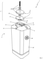
FIG. 1 shows an axonometric exploded view of a pole-cover cap according to the invention; -
FIG. 2 represents a detail of the pole-cover cap ofFIG. 1 in a sectional view. - With reference to the above mentioned figures, and in particular to
FIG. 1 , a pole-cover cap 1 is described which can be associated with the head of crop cover support poles. It comprises ahollow body 3 adapted to accommodate the head of the respective pole in the cavity thereof. It further comprises afixing assembly 4 of the cover. - According to an aspect of the invention, the
fixing assembly 4 comprises a plurality oflocking elements 6 coupled to each other and each of them dedicated to fixing corresponding components of the cover.Such locking elements 6 are typically, but not necessarily, screw elements such as washers, nuts and screws. The components of the cover, on the other hand, are generally wires, ropes (longitudinal and transverse to the structure of the cover), protective nets and/or sheets. - In aspects not falling under the scope of the invention, each locking element is dedicated to fixing multiple components of the cover or where multiple locking elements are necessary to fix a single component.
- According to an aspect of the invention, between the locking
elements 6 of thecap 1 there is afirst locking element 7 capable of fixing a ridge wire to the pole-cover cap 1. - According to the described embodiment, the
first locking element 7 is a washer. Obviously, such aspect should not be considered limiting for different embodiments of the first locking element. - According to another aspect of the invention, the shaped
body 3 comprises at the top thereof agroove 9 for the passage of the ridge wire on thecap 1. - Furthermore, in the embodiment of the invention which is described, such
shaped body 3 comprises anadditional groove 10 for the passage of ropes transverse to the ridge wire. Obviously, the shaped body may comprise multiple grooves or only one. - According to a further aspect of the invention, the shaped
body 3 also comprises arecess 12, obtained at the top thereof, intersecting thegrooves first locking element 7 so as to compress the ridge wire in therecess 12 itself. - In particular, the
side surface 14 of thefirst locking element 7 has a first shaping 15 and the correspondinginner surface 17 of therecess 12 has a second shaping 18 shaped to couple with thefirst shaping 15. More specifically, theshapings first locking element 7 in therecess 12, and consequently, to couple thefirst locking element 7 to thecap 1. - Advantageously, the pole-
cover cap 1 of the invention thus allows to ensure an adequate fixing of the cover components to the structure. - In particular, the coupling by rotation of the
first locking element 7 to the shapedbody 3 advantageously allows to simplify the operations of fixing the ridge wire to the poles with respect to the known systems. - Still advantageously, the same coupling by rotation allows the pressure exerted on the ridge wire to be adjusted. In fact, depending on the rotation angle impressed by the operator during the installation of the
first locking element 7, a more or less intense pressure is exerted on the ridge wire. - Still advantageously, the possibility of adjusting the pressure exerted on the ridge wire allows to obtain a partial fixing of the wire to the
cap 1 of the invention. Consequently, the pole-cover cap 1 of the invention allows to first install the cover with a first tensioning of the ridge wire and without incurring structural problems. At the end of the installation of all the components, thecap 1 of the invention allows to proceed with the definitive tensioning and fixing of the ridge wire without in any way affecting the other components of the cover. - Still advantageously, the coupling between the
first locking element 7 and the shapedbody 3 is easily reversible, simplifying any disassembly of the cover. - According to the embodiment described, the first shaping 15 comprises a substantially wedge-shaped
protrusion 20, while the second shaping 18 comprises a substantially counter-wedge-shapedgroove 21 adapted to accommodate the wedge-shapedprotrusion 20. - Obviously, the manufacture of the first and the second shaping is a feature which should not be understood in a limiting sense for the present invention. In particular, an alternative embodiment is not excluded where the second shaping comprises a substantially wedge-shaped protrusion and the first shaping comprises a substantially counter-wedge-shaped groove adapted to accommodate such protrusion.
- Further, according to a different embodiment variant not shown in the figures, the first shaping comprises a first thread while the second shaping comprises a second thread counter-shaped on the first to allow the screwing of the first locking element in the recess.
- According to the invention, the two shapings are such as to allow a bayonet-type engagement of the first locking element in the recess.
- According to another aspect of the invention, the
first locking element 7 has a throughhole 25 to allow the passage of ajunction group 26 of theother locking elements 6 forming the fixingassembly 4. - Advantageously, the presence of a through
hole 25 allows an independent coupling of theother locking elements 6 with respect to thefirst element 7. - Obviously, this aspect should not be considered limiting for different embodiments where the other locking elements are coupled to the cap by means of a plurality of junction groups.
- According to the described embodiment of the invention, the shaped
body 3 comprises ahole 28 on theside surface 29 thereof shaped to be struck by a fixing screw (not represented herein) of the pole-cover cap 1 to the pole head. - Advantageously, the use of a fixing screw allows a more stable coupling of the
cap 1 to the top of the poles. In other embodiments, the coupling is interlocking or where there are multiple holes to accommodate multiple fixing screws. - From what has been said it is evident that the object of the invention is also a crop cover comprising:
- at least a plurality of support poles;
- a plurality of cover components among which there is at least one ridge wire;
- a plurality of pole-cover caps according to the above and each associated with a respective pole for coupling the cover components thereto.
- A complete description of the crop cover of the invention is omitted here, since it would replicate what is already written about the same during the description of the pole-
cover cap 1. What is observed is that it achieves all the aforementioned advantages. - In light of the foregoing, it is understood that the pole-cover cap of the invention achieves all the intended objects.
- In particular, the pole-cover cap of the invention allows an adequate fixing of the components of a crop cover to a pole structure.
- Furthermore, the cap of the invention allows for a simplified fixing with respect to the locking systems present in the prior art.
- In fact, the pole-cover cap of the invention allows a partial fixing of the ridge wire during the assembly of the cover. On closer inspection, however, the fixing elements of the invention allow an adjustable pressure to be exerted on the ridge wire, further simplifying the aforementioned assembly.
- Finally, the locking system of the ridge wire to the cap of the invention is easily reversible.
- The invention is defined by the appended claims. In embodiments not covered by the claims all the details and steps may furthermore be replaced by other technically equivalent elements, and the materials may be different depending on the needs.
Claims (8)
- A pole-cover cap, which can be associated with the head of crop cover support poles, comprising a shaped hollow body (3) and a fixing assembly (4) of a cover, said fixing assembly (4) comprising a plurality of locking elements (6) coupled to each other and each dedicated to fixing corresponding components of the cover, among said locking elements (6) being comprised a first locking element (7) capable of fixing a ridge wire to said pole-cover cap (1), said shaped body (3) comprises:- at least one groove (9) obtained on the top of said shaped body (3) for the passage of the ridge wire;- at least one recess (12) obtained on the top of said shaped body (3), intersecting said groove (9) and shaped to accommodate therein at least a portion of said first locking element (7) so as to compress the ridge wire in said recess (12),the side surface (14) of said first locking element (7) having a first shaping (15) and the corresponding inner surface (17) of said recess (12) having a second shaping (18) such as to allow the mutual coupling thereof by rotation of said first locking element (7) in said recess (12),characterized in that said first and second shapes are shaped so as to allow a bayonet-type engagement of said first locking element (7) in said recess (12).
- A pole-cover cap according to claim 1, characterized in that said first shaping (15) comprises a substantially wedge-shaped protrusion (20) and said second shaping (18) comprises a substantially counter-wedge-shaped groove (21) adapted to accommodate said wedge-shaped protrusion (20).
- A pole-cover cap according to claim 1, characterized in that said second shaping comprises a substantially wedge-shaped protrusion and said first shaping comprises a substantially counter-wedge-shaped groove adapted to accommodate said wedge-shaped protrusion.
- A pole-cover cap according to claim 1, characterized in that said first shaping comprises a first thread and said second shaping comprises a second counter-shaped thread on said first thread.
- A pole-cover cap according to any one of the previous claims, characterized in that said first locking element (7) has a through hole (25) to allow the passage of a junction group (26) of one or more of said locking elements (6) composing said fixing assembly (4).
- A pole-cover cap according to any one of the previous claims, characterized in that said first locking element (7) is a washer.
- A pole-cover cap according to any one of the previous claims, characterized in that said shaped body (3) comprises at least one hole (28) on the side surface (29) thereof shaped to be struck by a fixing screw of said pole-cover cap (1) to the pole head.
- A crop cover comprising:- at least a plurality of support poles;- a plurality of cover components among which there is at least one ridge wire;- a plurality of pole-cover caps (1) according to one or more of the previous claims, each associated with one respective of said poles to couple said cover components to said poles.
Applications Claiming Priority (1)
| Application Number | Priority Date | Filing Date | Title |
|---|---|---|---|
| IT102019000018746A IT201900018746A1 (en) | 2019-10-14 | 2019-10-14 | A CAP CAPS |
Publications (3)
| Publication Number | Publication Date |
|---|---|
| EP3808169A1 EP3808169A1 (en) | 2021-04-21 |
| EP3808169B1 true EP3808169B1 (en) | 2024-04-17 |
| EP3808169C0 EP3808169C0 (en) | 2024-04-17 |
Family
ID=69701336
Family Applications (1)
| Application Number | Title | Priority Date | Filing Date |
|---|---|---|---|
| EP20201129.2A Active EP3808169B1 (en) | 2019-10-14 | 2020-10-09 | A pile-covering hood |
Country Status (2)
| Country | Link |
|---|---|
| EP (1) | EP3808169B1 (en) |
| IT (1) | IT201900018746A1 (en) |
Family Cites Families (2)
| Publication number | Priority date | Publication date | Assignee | Title |
|---|---|---|---|---|
| DE102010001692A1 (en) * | 2010-02-09 | 2011-08-11 | BayWa Aktiengesellschaft, 81925 | Hood for placing on a concrete post |
| CN206707403U (en) * | 2017-03-27 | 2017-12-05 | 威海新元果业技术服务有限公司 | Concrete stake stake top fixation with steel wire component |
-
2019
- 2019-10-14 IT IT102019000018746A patent/IT201900018746A1/en unknown
-
2020
- 2020-10-09 EP EP20201129.2A patent/EP3808169B1/en active Active
Also Published As
| Publication number | Publication date |
|---|---|
| IT201900018746A1 (en) | 2021-04-14 |
| EP3808169C0 (en) | 2024-04-17 |
| EP3808169A1 (en) | 2021-04-21 |
Similar Documents
| Publication | Publication Date | Title |
|---|---|---|
| US10148004B2 (en) | Roof-mount antenna mounting structure | |
| US10132480B2 (en) | Landscape light | |
| JP3157675U (en) | Connecting device for tree support device | |
| US5295727A (en) | Bicycle seat adjusting device | |
| US5178397A (en) | Lacrosse stick head frame | |
| US9554570B2 (en) | Bird control assemblies for protecting wires | |
| KR20120122118A (en) | a bolt, nut burglarproof cap | |
| EP3808169A1 (en) | A pile-covering hood | |
| US6928671B2 (en) | Tie down assembly for pool covers and pool cover incorporating same | |
| US4750401A (en) | Lug nut assembly for drums | |
| US2935304A (en) | Chain fence | |
| US20060150483A1 (en) | Tree support assembly | |
| US6459026B1 (en) | Drum tensioner holding | |
| AT400778B (en) | MEMBRANOPHONE AND ATTENUATOR FOR A MEMBRANOPHONE | |
| DE10148409C2 (en) | Protection device for the turnbuckle of a conga | |
| KR101336915B1 (en) | a bolt, nut burglarproof cap | |
| FI82972C (en) | SKRUVFOERBINDNING. | |
| US9799311B2 (en) | Marching tenor drum assembly having unitary multiple-drum mounting frame | |
| KR100320687B1 (en) | Safety manhole with double lid | |
| JP7166617B2 (en) | Railing support structure | |
| KR200410319Y1 (en) | Rock Fixation Device for Rockfall Protection | |
| FR2658730A1 (en) | Special profile for football or rugby goals | |
| JP7043432B2 (en) | Fastening fixture and fastening structure | |
| JP7274744B2 (en) | Attachment device for competition goals | |
| CA3138408C (en) | Lockable adjustable standoff |
Legal Events
| Date | Code | Title | Description |
|---|---|---|---|
| PUAI | Public reference made under article 153(3) epc to a published international application that has entered the european phase |
Free format text: ORIGINAL CODE: 0009012 |
|
| STAA | Information on the status of an ep patent application or granted ep patent |
Free format text: STATUS: THE APPLICATION HAS BEEN PUBLISHED |
|
| AK | Designated contracting states |
Kind code of ref document: A1 Designated state(s): AL AT BE BG CH CY CZ DE DK EE ES FI FR GB GR HR HU IE IS IT LI LT LU LV MC MK MT NL NO PL PT RO RS SE SI SK SM TR |
|
| AX | Request for extension of the european patent |
Extension state: BA ME |
|
| STAA | Information on the status of an ep patent application or granted ep patent |
Free format text: STATUS: REQUEST FOR EXAMINATION WAS MADE |
|
| 17P | Request for examination filed |
Effective date: 20211021 |
|
| RBV | Designated contracting states (corrected) |
Designated state(s): AL AT BE BG CH CY CZ DE DK EE ES FI FR GB GR HR HU IE IS IT LI LT LU LV MC MK MT NL NO PL PT RO RS SE SI SK SM TR |
|
| STAA | Information on the status of an ep patent application or granted ep patent |
Free format text: STATUS: EXAMINATION IS IN PROGRESS |
|
| 17Q | First examination report despatched |
Effective date: 20230503 |
|
| GRAP | Despatch of communication of intention to grant a patent |
Free format text: ORIGINAL CODE: EPIDOSNIGR1 |
|
| STAA | Information on the status of an ep patent application or granted ep patent |
Free format text: STATUS: GRANT OF PATENT IS INTENDED |
|
| INTG | Intention to grant announced |
Effective date: 20240105 |
|
| GRAS | Grant fee paid |
Free format text: ORIGINAL CODE: EPIDOSNIGR3 |
|
| GRAA | (expected) grant |
Free format text: ORIGINAL CODE: 0009210 |
|
| STAA | Information on the status of an ep patent application or granted ep patent |
Free format text: STATUS: THE PATENT HAS BEEN GRANTED |
|
| AK | Designated contracting states |
Kind code of ref document: B1 Designated state(s): AL AT BE BG CH CY CZ DE DK EE ES FI FR GB GR HR HU IE IS IT LI LT LU LV MC MK MT NL NO PL PT RO RS SE SI SK SM TR |
|
| REG | Reference to a national code |
Ref country code: GB Ref legal event code: FG4D |
|
| REG | Reference to a national code |
Ref country code: CH Ref legal event code: EP |
|
| REG | Reference to a national code |
Ref country code: IE Ref legal event code: FG4D Ref country code: DE Ref legal event code: R096 Ref document number: 602020029068 Country of ref document: DE |
|
| U01 | Request for unitary effect filed |
Effective date: 20240507 |
|
| U07 | Unitary effect registered |
Designated state(s): AT BE BG DE DK EE FI FR IT LT LU LV MT NL PT SE SI Effective date: 20240521 |
|
| PG25 | Lapsed in a contracting state [announced via postgrant information from national office to epo] |
Ref country code: IS Free format text: LAPSE BECAUSE OF FAILURE TO SUBMIT A TRANSLATION OF THE DESCRIPTION OR TO PAY THE FEE WITHIN THE PRESCRIBED TIME-LIMIT Effective date: 20240817 |
|
| PG25 | Lapsed in a contracting state [announced via postgrant information from national office to epo] |
Ref country code: HR Free format text: LAPSE BECAUSE OF FAILURE TO SUBMIT A TRANSLATION OF THE DESCRIPTION OR TO PAY THE FEE WITHIN THE PRESCRIBED TIME-LIMIT Effective date: 20240417 |
|
| PG25 | Lapsed in a contracting state [announced via postgrant information from national office to epo] |
Ref country code: GR Free format text: LAPSE BECAUSE OF FAILURE TO SUBMIT A TRANSLATION OF THE DESCRIPTION OR TO PAY THE FEE WITHIN THE PRESCRIBED TIME-LIMIT Effective date: 20240718 |
|
| PG25 | Lapsed in a contracting state [announced via postgrant information from national office to epo] |
Ref country code: ES Free format text: LAPSE BECAUSE OF FAILURE TO SUBMIT A TRANSLATION OF THE DESCRIPTION OR TO PAY THE FEE WITHIN THE PRESCRIBED TIME-LIMIT Effective date: 20240417 |
|
| PG25 | Lapsed in a contracting state [announced via postgrant information from national office to epo] |
Ref country code: PL Free format text: LAPSE BECAUSE OF FAILURE TO SUBMIT A TRANSLATION OF THE DESCRIPTION OR TO PAY THE FEE WITHIN THE PRESCRIBED TIME-LIMIT Effective date: 20240417 |
|
| PG25 | Lapsed in a contracting state [announced via postgrant information from national office to epo] |
Ref country code: PL Free format text: LAPSE BECAUSE OF FAILURE TO SUBMIT A TRANSLATION OF THE DESCRIPTION OR TO PAY THE FEE WITHIN THE PRESCRIBED TIME-LIMIT Effective date: 20240417 Ref country code: NO Free format text: LAPSE BECAUSE OF FAILURE TO SUBMIT A TRANSLATION OF THE DESCRIPTION OR TO PAY THE FEE WITHIN THE PRESCRIBED TIME-LIMIT Effective date: 20240717 Ref country code: IS Free format text: LAPSE BECAUSE OF FAILURE TO SUBMIT A TRANSLATION OF THE DESCRIPTION OR TO PAY THE FEE WITHIN THE PRESCRIBED TIME-LIMIT Effective date: 20240817 Ref country code: HR Free format text: LAPSE BECAUSE OF FAILURE TO SUBMIT A TRANSLATION OF THE DESCRIPTION OR TO PAY THE FEE WITHIN THE PRESCRIBED TIME-LIMIT Effective date: 20240417 Ref country code: GR Free format text: LAPSE BECAUSE OF FAILURE TO SUBMIT A TRANSLATION OF THE DESCRIPTION OR TO PAY THE FEE WITHIN THE PRESCRIBED TIME-LIMIT Effective date: 20240718 Ref country code: ES Free format text: LAPSE BECAUSE OF FAILURE TO SUBMIT A TRANSLATION OF THE DESCRIPTION OR TO PAY THE FEE WITHIN THE PRESCRIBED TIME-LIMIT Effective date: 20240417 Ref country code: RS Free format text: LAPSE BECAUSE OF FAILURE TO SUBMIT A TRANSLATION OF THE DESCRIPTION OR TO PAY THE FEE WITHIN THE PRESCRIBED TIME-LIMIT Effective date: 20240717 |
|
| U20 | Renewal fee for the european patent with unitary effect paid |
Year of fee payment: 5 Effective date: 20241031 |
|
| REG | Reference to a national code |
Ref country code: DE Ref legal event code: R097 Ref document number: 602020029068 Country of ref document: DE |
|
| PG25 | Lapsed in a contracting state [announced via postgrant information from national office to epo] |
Ref country code: CZ Free format text: LAPSE BECAUSE OF FAILURE TO SUBMIT A TRANSLATION OF THE DESCRIPTION OR TO PAY THE FEE WITHIN THE PRESCRIBED TIME-LIMIT Effective date: 20240417 |
|
| PG25 | Lapsed in a contracting state [announced via postgrant information from national office to epo] |
Ref country code: SK Free format text: LAPSE BECAUSE OF FAILURE TO SUBMIT A TRANSLATION OF THE DESCRIPTION OR TO PAY THE FEE WITHIN THE PRESCRIBED TIME-LIMIT Effective date: 20240417 Ref country code: RO Free format text: LAPSE BECAUSE OF FAILURE TO SUBMIT A TRANSLATION OF THE DESCRIPTION OR TO PAY THE FEE WITHIN THE PRESCRIBED TIME-LIMIT Effective date: 20240417 |
|
| PG25 | Lapsed in a contracting state [announced via postgrant information from national office to epo] |
Ref country code: SM Free format text: LAPSE BECAUSE OF FAILURE TO SUBMIT A TRANSLATION OF THE DESCRIPTION OR TO PAY THE FEE WITHIN THE PRESCRIBED TIME-LIMIT Effective date: 20240417 |
|
| PG25 | Lapsed in a contracting state [announced via postgrant information from national office to epo] |
Ref country code: SM Free format text: LAPSE BECAUSE OF FAILURE TO SUBMIT A TRANSLATION OF THE DESCRIPTION OR TO PAY THE FEE WITHIN THE PRESCRIBED TIME-LIMIT Effective date: 20240417 Ref country code: SK Free format text: LAPSE BECAUSE OF FAILURE TO SUBMIT A TRANSLATION OF THE DESCRIPTION OR TO PAY THE FEE WITHIN THE PRESCRIBED TIME-LIMIT Effective date: 20240417 Ref country code: RO Free format text: LAPSE BECAUSE OF FAILURE TO SUBMIT A TRANSLATION OF THE DESCRIPTION OR TO PAY THE FEE WITHIN THE PRESCRIBED TIME-LIMIT Effective date: 20240417 Ref country code: CZ Free format text: LAPSE BECAUSE OF FAILURE TO SUBMIT A TRANSLATION OF THE DESCRIPTION OR TO PAY THE FEE WITHIN THE PRESCRIBED TIME-LIMIT Effective date: 20240417 |
|
| PLBE | No opposition filed within time limit |
Free format text: ORIGINAL CODE: 0009261 |
|
| STAA | Information on the status of an ep patent application or granted ep patent |
Free format text: STATUS: NO OPPOSITION FILED WITHIN TIME LIMIT |
|
| 26N | No opposition filed |
Effective date: 20250120 |
|
| REG | Reference to a national code |
Ref country code: CH Ref legal event code: PL |
|
| GBPC | Gb: european patent ceased through non-payment of renewal fee |
Effective date: 20241009 |
|
| PG25 | Lapsed in a contracting state [announced via postgrant information from national office to epo] |
Ref country code: MC Free format text: LAPSE BECAUSE OF FAILURE TO SUBMIT A TRANSLATION OF THE DESCRIPTION OR TO PAY THE FEE WITHIN THE PRESCRIBED TIME-LIMIT Effective date: 20240417 |
|
| PG25 | Lapsed in a contracting state [announced via postgrant information from national office to epo] |
Ref country code: GB Free format text: LAPSE BECAUSE OF NON-PAYMENT OF DUE FEES Effective date: 20241009 |
|
| PG25 | Lapsed in a contracting state [announced via postgrant information from national office to epo] |
Ref country code: CH Free format text: LAPSE BECAUSE OF NON-PAYMENT OF DUE FEES Effective date: 20241031 |
|
| PG25 | Lapsed in a contracting state [announced via postgrant information from national office to epo] |
Ref country code: IE Free format text: LAPSE BECAUSE OF NON-PAYMENT OF DUE FEES Effective date: 20241009 |
|
| U20 | Renewal fee for the european patent with unitary effect paid |
Year of fee payment: 6 Effective date: 20251031 |
|
| PG25 | Lapsed in a contracting state [announced via postgrant information from national office to epo] |
Ref country code: CY Free format text: LAPSE BECAUSE OF FAILURE TO SUBMIT A TRANSLATION OF THE DESCRIPTION OR TO PAY THE FEE WITHIN THE PRESCRIBED TIME-LIMIT; INVALID AB INITIO Effective date: 20201009 |
|
| PG25 | Lapsed in a contracting state [announced via postgrant information from national office to epo] |
Ref country code: HU Free format text: LAPSE BECAUSE OF FAILURE TO SUBMIT A TRANSLATION OF THE DESCRIPTION OR TO PAY THE FEE WITHIN THE PRESCRIBED TIME-LIMIT; INVALID AB INITIO Effective date: 20201009 |