EP3807738B1 - Auxiliary control electronic device of mobile terminal - Google Patents
Auxiliary control electronic device of mobile terminal Download PDFInfo
- Publication number
- EP3807738B1 EP3807738B1 EP19857741.3A EP19857741A EP3807738B1 EP 3807738 B1 EP3807738 B1 EP 3807738B1 EP 19857741 A EP19857741 A EP 19857741A EP 3807738 B1 EP3807738 B1 EP 3807738B1
- Authority
- EP
- European Patent Office
- Prior art keywords
- holding portion
- main body
- mobile terminal
- disposed
- internal space
- Prior art date
- Legal status (The legal status is an assumption and is not a legal conclusion. Google has not performed a legal analysis and makes no representation as to the accuracy of the status listed.)
- Active
Links
Images








Classifications
-
- G—PHYSICS
- G06—COMPUTING OR CALCULATING; COUNTING
- G06F—ELECTRIC DIGITAL DATA PROCESSING
- G06F1/00—Details not covered by groups G06F3/00 - G06F13/00 and G06F21/00
- G06F1/16—Constructional details or arrangements
- G06F1/1613—Constructional details or arrangements for portable computers
- G06F1/1632—External expansion units, e.g. docking stations
-
- H—ELECTRICITY
- H04—ELECTRIC COMMUNICATION TECHNIQUE
- H04B—TRANSMISSION
- H04B1/00—Details of transmission systems, not covered by a single one of groups H04B3/00 - H04B13/00; Details of transmission systems not characterised by the medium used for transmission
- H04B1/38—Transceivers, i.e. devices in which transmitter and receiver form a structural unit and in which at least one part is used for functions of transmitting and receiving
- H04B1/3827—Portable transceivers
- H04B1/3888—Arrangements for carrying or protecting transceivers
-
- A—HUMAN NECESSITIES
- A63—SPORTS; GAMES; AMUSEMENTS
- A63F—CARD, BOARD, OR ROULETTE GAMES; INDOOR GAMES USING SMALL MOVING PLAYING BODIES; VIDEO GAMES; GAMES NOT OTHERWISE PROVIDED FOR
- A63F13/00—Video games, i.e. games using an electronically generated display having two or more dimensions
- A63F13/20—Input arrangements for video game devices
- A63F13/24—Constructional details thereof, e.g. game controllers with detachable joystick handles
-
- A—HUMAN NECESSITIES
- A63—SPORTS; GAMES; AMUSEMENTS
- A63F—CARD, BOARD, OR ROULETTE GAMES; INDOOR GAMES USING SMALL MOVING PLAYING BODIES; VIDEO GAMES; GAMES NOT OTHERWISE PROVIDED FOR
- A63F13/00—Video games, i.e. games using an electronically generated display having two or more dimensions
- A63F13/90—Constructional details or arrangements of video game devices not provided for in groups A63F13/20 or A63F13/25, e.g. housing, wiring, connections or cabinets
- A63F13/92—Video game devices specially adapted to be hand-held while playing
-
- A—HUMAN NECESSITIES
- A63—SPORTS; GAMES; AMUSEMENTS
- A63F—CARD, BOARD, OR ROULETTE GAMES; INDOOR GAMES USING SMALL MOVING PLAYING BODIES; VIDEO GAMES; GAMES NOT OTHERWISE PROVIDED FOR
- A63F13/00—Video games, i.e. games using an electronically generated display having two or more dimensions
- A63F13/90—Constructional details or arrangements of video game devices not provided for in groups A63F13/20 or A63F13/25, e.g. housing, wiring, connections or cabinets
- A63F13/98—Accessories, i.e. detachable arrangements optional for the use of the video game device, e.g. grip supports of game controllers
-
- G—PHYSICS
- G06—COMPUTING OR CALCULATING; COUNTING
- G06F—ELECTRIC DIGITAL DATA PROCESSING
- G06F1/00—Details not covered by groups G06F3/00 - G06F13/00 and G06F21/00
- G06F1/16—Constructional details or arrangements
- G06F1/1613—Constructional details or arrangements for portable computers
- G06F1/1633—Constructional details or arrangements of portable computers not specific to the type of enclosures covered by groups G06F1/1615 - G06F1/1626
- G06F1/1635—Details related to the integration of battery packs and other power supplies such as fuel cells or integrated AC adapter
-
- G—PHYSICS
- G06—COMPUTING OR CALCULATING; COUNTING
- G06F—ELECTRIC DIGITAL DATA PROCESSING
- G06F1/00—Details not covered by groups G06F3/00 - G06F13/00 and G06F21/00
- G06F1/16—Constructional details or arrangements
- G06F1/20—Cooling means
- G06F1/203—Cooling means for portable computers, e.g. for laptops
-
- H—ELECTRICITY
- H05—ELECTRIC TECHNIQUES NOT OTHERWISE PROVIDED FOR
- H05K—PRINTED CIRCUITS; CASINGS OR CONSTRUCTIONAL DETAILS OF ELECTRIC APPARATUS; MANUFACTURE OF ASSEMBLAGES OF ELECTRICAL COMPONENTS
- H05K7/00—Constructional details common to different types of electric apparatus
- H05K7/20—Modifications to facilitate cooling, ventilating, or heating
- H05K7/20009—Modifications to facilitate cooling, ventilating, or heating using a gaseous coolant in electronic enclosures
- H05K7/20136—Forced ventilation, e.g. by fans
- H05K7/20154—Heat dissipaters coupled to components
-
- H—ELECTRICITY
- H05—ELECTRIC TECHNIQUES NOT OTHERWISE PROVIDED FOR
- H05K—PRINTED CIRCUITS; CASINGS OR CONSTRUCTIONAL DETAILS OF ELECTRIC APPARATUS; MANUFACTURE OF ASSEMBLAGES OF ELECTRICAL COMPONENTS
- H05K7/00—Constructional details common to different types of electric apparatus
- H05K7/20—Modifications to facilitate cooling, ventilating, or heating
- H05K7/20009—Modifications to facilitate cooling, ventilating, or heating using a gaseous coolant in electronic enclosures
- H05K7/20136—Forced ventilation, e.g. by fans
- H05K7/20172—Fan mounting or fan specifications
-
- H—ELECTRICITY
- H05—ELECTRIC TECHNIQUES NOT OTHERWISE PROVIDED FOR
- H05K—PRINTED CIRCUITS; CASINGS OR CONSTRUCTIONAL DETAILS OF ELECTRIC APPARATUS; MANUFACTURE OF ASSEMBLAGES OF ELECTRICAL COMPONENTS
- H05K7/00—Constructional details common to different types of electric apparatus
- H05K7/20—Modifications to facilitate cooling, ventilating, or heating
- H05K7/2039—Modifications to facilitate cooling, ventilating, or heating characterised by the heat transfer by conduction from the heat generating element to a dissipating body
- H05K7/20409—Outer radiating structures on heat dissipating housings, e.g. fins integrated with the housing
-
- H—ELECTRICITY
- H04—ELECTRIC COMMUNICATION TECHNIQUE
- H04B—TRANSMISSION
- H04B1/00—Details of transmission systems, not covered by a single one of groups H04B3/00 - H04B13/00; Details of transmission systems not characterised by the medium used for transmission
- H04B1/38—Transceivers, i.e. devices in which transmitter and receiver form a structural unit and in which at least one part is used for functions of transmitting and receiving
- H04B1/3827—Portable transceivers
Definitions
- the disclosure relates to an auxiliary control device capable of supporting a mobile terminal while enabling the mobile terminal to be manipulated more freely and conveniently.
- Mobile terminals may perform various functions in a complex manner, thereby producing a high performance in order to realize an advanced performance.
- a touch screen may be mainly used as an input means of the mobile terminal.
- US2015/174482 discloses a game controller for use with handheld game devices, which includes a cradle for holding the smartphone.
- the cradle is pivotable between an open position, extending from a base of the game controller, and a closed position in which the cradle is about a bottom wall of the base.
- US2016/107082 discloses a game controller device including an assembling component and at least one input module.
- the at least one input module is movably connected to a side of the assembling component to have a first using position and a second using position.
- US2015/031452 discloses a game controller assembly which is mechanically and communicatively connected to a user computing device to be used to play games.
- the game controller assembly is detachably coupled mechanically and electrically to the user computing device.
- a touch screen which is a primary input means of the mobile terminal, it may be difficult or inconvenient to perform an elaborate manipulation when using a particular application.
- an auxiliary electronic controller of a mobile terminal according to claim 1 is provided.
- the disclosure provides an auxiliary control device that can be manipulated elaborately and conveniently when a mobile terminal is manipulated.
- the disclosure further provides an auxiliary control device that can solve a power shortage problem and a performance deterioration problem caused by heat generation that may occur in a process of using a mobile terminal.
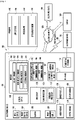
- Fig. 1 is a block diagram illustrating an electronic device 101 in a network environment 100 according to certain embodiments.
- the electronic device 101 in the network environment 100 may communicate with an electronic device 102 via a first network 198 (e.g., a short-range wireless communication network), or an electronic device 104 or a server 108 via a second network 199 (e.g., a long-range wireless communication network).
- the electronic device 101 may communicate with the electronic device 104 via the server 108.
- the electronic device 101 may include a processor 120, memory 130, an input device 150, a sound output device 155, a display device 160, an audio module 170, a sensor module 176, an interface 177, a haptic module 179, a camera module 180, a power management module 188, a battery 189, a communication module 190, a subscriber identification module (SIM) 196, or an antenna module 197.
- at least one (e.g., the display device 160 or the camera module 180) of the components may be omitted from the electronic device 101, or one or more other components may be added in the electronic device 101.
- some of the components may be implemented as single integrated circuitry.
- the sensor module 176 e.g., a fingerprint sensor, an iris sensor, or an illuminance sensor
- the display device 160 e.g., a display
- an haptic module 179 e.g., a camera module 180
- a power management module 188 e.g., the display
- the processor 120 may execute, for example, software (e.g., a program 140) to control at least one other component (e.g., a hardware or software component) of the electronic device 101 coupled with the processor 120, and may perform various data processing or computation. According to one embodiment, as at least part of the data processing or computation, the processor 120 may load a command or data received from another component (e.g., the sensor module 176 or the communication module 190) in volatile memory 132, process the command or the data stored in the volatile memory 132, and store resulting data in non-volatile memory 134.
- software e.g., a program 140
- the processor 120 may load a command or data received from another component (e.g., the sensor module 176 or the communication module 190) in volatile memory 132, process the command or the data stored in the volatile memory 132, and store resulting data in non-volatile memory 134.
- the processor 120 may include a main processor 121 (e.g., a central processing unit (CPU) or an application processor (AP)), and an auxiliary processor 123 (e.g., a graphics processing unit (GPU), an image signal processor (ISP), a sensor hub processor, or a communication processor (CP)) that is operable independently from, or in conjunction with, the main processor 121.
- auxiliary processor 123 may be adapted to consume less power than the main processor 121, or to be specific to a specified function.
- the auxiliary processor 123 may be implemented as separate from, or as part of the main processor 121.
- the auxiliary processor 123 may control at least some of functions or states related to at least one component (e.g., the display device 160, the sensor module 176, or the communication module 190) among the components of the electronic device 101, instead of the main processor 121 while the main processor 121 is in an inactive (e.g., sleep) state, or together with the main processor 121 while the main processor 121 is in an active state (e.g., executing an application).
- the auxiliary processor 123 e.g., an image signal processor or a communication processor
- the memory 130 may store various data used by at least one component (e.g., the processor 120 or the sensor module 176) of the electronic device 101.
- the various data may include, for example, software (e.g., the program 140) and input data or output data for a command related thererto.
- the memory 130 may include the volatile memory 132 or the non-volatile memory 134.
- the program 140 may be stored in the memory 130 as software, and may include, for example, an operating system (OS) 142, middleware 144, or an application 146.
- OS operating system
- middleware middleware
- application application
- the input device 150 may receive a command or data to be used by other component (e.g., the processor 120) of the electronic device 101, from the outside (e.g., a user) of the electronic device 101.
- the input device 150 may include, for example, a microphone, a mouse, or a keyboard.
- the sound output device 155 may output sound signals to the outside of the electronic device 101.
- the sound output device 155 may include, for example, a speaker or a receiver.
- the speaker may be used for general purposes, such as playing multimedia or playing record, and the receiver may be used for an incoming calls. According to an embodiment, the receiver may be implemented as separate from, or as part of the speaker.
- the display device 160 may visually provide information to the outside (e.g., a user) of the electronic device 101.
- the display device 160 may include, for example, a display, a hologram device, or a projector and control circuitry to control a corresponding one of the display, hologram device, and projector.
- the display device 160 may include touch circuitry adapted to detect a touch, or sensor circuitry (e.g., a pressure sensor) adapted to measure the intensity of force incurred by the touch.
- the audio module 170 may convert a sound into an electrical signal and vice versa. According to an embodiment, the audio module 170 may obtain the sound via the input device 150, or output the sound via the sound output device 155 or a headphone of an external electronic device (e.g., an electronic device 102) directly (e.g., wiredly) or wirelessly coupled with the electronic device 101.
- an external electronic device e.g., an electronic device 102
- directly e.g., wiredly
- wirelessly e.g., wirelessly
- the sensor module 176 may detect an operational state (e.g., power or temperature) of the electronic device 101 or an environmental state (e.g., a state of a user) external to the electronic device 101, and then generate an electrical signal or data value corresponding to the detected state.
- the sensor module 176 may include, for example, a gesture sensor, a gyro sensor, an atmospheric pressure sensor, a magnetic sensor, an acceleration sensor, a grip sensor, a proximity sensor, a color sensor, an infrared (IR) sensor, a biometric sensor, a temperature sensor, a humidity sensor, or an illuminance sensor.
- the interface 177 may support one or more specified protocols to be used for the electronic device 101 to be coupled with the external electronic device (e.g., the electronic device 102) directly (e.g., wiredly) or wirelessly.
- the interface 177 may include, for example, a high definition multimedia interface (HDMI), a universal serial bus (USB) interface, a secure digital (SD) card interface, or an audio interface.
- HDMI high definition multimedia interface
- USB universal serial bus
- SD secure digital
- a connecting terminal 178 may include a connector via which the electronic device 101 may be physically connected with the external electronic device (e.g., the electronic device 102).
- the connecting terminal 178 may include, for example, a HDMI connector, a USB connector, a SD card connector, or an audio connector (e.g., a headphone connector),
- the haptic module 179 may convert an electrical signal into a mechanical stimulus (e.g., a vibration or a movement) or electrical stimulus which may be recognized by a user via his tactile sensation or kinesthetic sensation.
- the haptic module 179 may include, for example, a motor, a piezoelectric element, or an electric stimulator.
- the camera module 180 may capture a still image or moving images.
- the camera module 180 may include one or more lenses, image sensors, image signal processors, or flashes.
- the power management module 188 may manage power supplied to the electronic device 101.
- the power management module 188 may be implemented as at least part of, for example, a power management integrated circuit (PMIC).
- PMIC power management integrated circuit
- the battery 189 may supply power to at least one component of the electronic device 101.
- the battery 189 may include, for example, a primary cell which is not rechargeable, a secondary cell which is rechargeable, or a fuel cell.
- the communication module 190 may support establishing a direct (e.g., wired) communication channel or a wireless communication channel between the electronic device 101 and the external electronic device (e.g., the electronic device 102, the electronic device 104, or the server 108) and performing communication via the established communication channel.
- the communication module 190 may include one or more communication processors that are operable independently from the processor 120 (e.g., the application processor (AP)) and supports a direct (e.g., wired) communication or a wireless communication.
- AP application processor
- the communication module 190 may include a wireless communication module 192 (e.g., a cellular communication module, a short-range wireless communication module, or a global navigation satellite system (GNSS) communication module) or a wired communication module 194 (e.g., a local area network (LAN) communication module or a power line communication (PLC) module).
- a wireless communication module 192 e.g., a cellular communication module, a short-range wireless communication module, or a global navigation satellite system (GNSS) communication module
- GNSS global navigation satellite system
- wired communication module 194 e.g., a local area network (LAN) communication module or a power line communication (PLC) module.
- LAN local area network
- PLC power line communication
- a corresponding one of these communication modules may communicate with the external electronic device via the first network 198 (e.g., a short-range communication network, such as BluetoothTM, wireless-fidelity (Wi-Fi) direct, or infrared data association (IrDA)) or the second network 199 (e.g., a long-range communication network, such as a cellular network, the Internet, or a computer network (e.g., LAN or wide area network (WAN)).
- the first network 198 e.g., a short-range communication network, such as BluetoothTM, wireless-fidelity (Wi-Fi) direct, or infrared data association (IrDA)
- the second network 199 e.g., a long-range communication network, such as a cellular network, the Internet, or a computer network (e.g., LAN or wide area network (WAN)
- These various types of communication modules may be implemented as a single component (e.g., a single chip), or may be implemented as multi components (e.
- the wireless communication module 192 may identify and authenticate the electronic device 101 in a communication network, such as the first network 198 or the second network 199, using subscriber information (e.g., international mobile subscriber identity (IMSI)) stored in the subscriber identification module 196.
- subscriber information e.g., international mobile subscriber identity (IMSI)
- the antenna module 197 may transmit or receive a signal or power to or from the outside (e.g., the external electronic device) of the electronic device 101.
- the antenna module 197 may include one or more antennas, and, therefrom, at least one antenna appropriate for a communication scheme used in the communication network, such as the first network 198 or the second network 199, may be selected, for example, by the communication module 190 (e.g., the wireless communication module 192).
- the signal or the power may then be transmitted or received between the communication module 190 and the external electronic device via the selected at least one antenna.
- At least some of the above-described components may be coupled mutually and communicate signals (e.g., commands or data) therebetween via an inter-peripheral communication scheme (e.g., a bus, general purpose input and output (GPIO), serial peripheral interface (SPI), or mobile industry processor interface (MIPI)).
- an inter-peripheral communication scheme e.g., a bus, general purpose input and output (GPIO), serial peripheral interface (SPI), or mobile industry processor interface (MIPI)
- commands or data may be transmitted or received between the electronic device 101 and the external electronic device 104 via the server 108 coupled with the second network 199.
- Each of the electronic devices 102 and 104 may be a device of a same type as, or a different type, from the electronic device 101.
- all or some of operations to be executed at the electronic device 101 may be executed at one or more of the external electronic devices 102, 104, or 108. For example, if the electronic device 101 should perform a function or a service automatically, or in response to a request from a user or another device, the electronic device 101, instead of, or in addition to, executing the function or the service, may request the one or more external electronic devices to perform at least part of the function or the service.
- the one or more external electronic devices receiving the request may perform the at least part of the function or the service requested, or an additional function or an additional service related to the request, and transfer an outcome of the performing to the electronic device 101.
- the electronic device 101 may provide the outcome, with or without further processing of the outcome, as at least part of a reply to the request.
- a cloud computing, distributed computing, or client-server computing technology may be used, for example.
- the electronic device may be one of various types of electronic devices.
- the electronic devices may include, for example, a portable communication device (e.g., a smart phone), a computer device, a portable multimedia device, a portable medical device, a camera, a wearable device, or a home appliance. According to an embodiment of the disclosure, the electronic devices are not limited to those described above.
- each of such phrases as “A or B,” “at least one of A and B,” “at least one of A or B,” “A, B, or C,” “at least one of A, B, and C,” and “at least one of A, B, or C,” may include all possible combinations of the items enumerated together in a corresponding one of the phrases.
- such terms as “1st” and “2nd,” or “first” and “second” may be used to simply distinguish a corresponding component from another, and does not limit the components in other aspect (e.g., importance or order).
- an element e.g., a first element
- the element may be coupled with the other element directly (e.g., wiredly), wirelessly, or via a third element.
- module may include a unit implemented in hardware, hardware programmed by software, and may interchangeably be used with other terms, for example, “logic,” “logic block,” “part,” or “circuitry”.
- a module may be a single integral component, or a minimum unit or part thereof, adapted to perform one or more functions.
- the module may be implemented in a form of an application-specific integrated circuit (ASIC).
- ASIC application-specific integrated circuit
- Certain embodiments as set forth herein may be implemented as software (e.g., the program 140) including one or more instructions that are stored in a storage medium (e.g., internal memory 136 or external memory 138) that is readable by a machine (e.g., the electronic device 101).
- a processor e.g., the processor 120
- the machine e.g., the electronic device 101
- the one or more instructions may include a code generated by a complier or a code executable by an interpreter.
- the machine-readable storage medium may be provided in the form of a non-transitory storage medium.
- non-transitory simply means that the storage medium is a tangible device, and does not include a signal (e.g., an electromagnetic wave), but this term does not differentiate between where data is semi-permanently stored in the storage medium and where the data is temporarily stored in the storage medium.
- a method may be included and provided in a computer program product.
- the computer program product may be traded as a product between a seller and a buyer.
- the computer program product may be distributed in the form of a machine-readable storage medium (e.g., compact disc read only memory (CD-ROM)), or be distributed (e.g., downloaded or uploaded) online via an application store (e.g., Play StoreTM), or between two user devices (e.g., smart phones) directly. If distributed online, at least part of the computer program product may be temporarily generated or at least temporarily stored in the machine-readable storage medium, such as memory of the manufacturer's server, a server of the application store, or a relay server.
- CD-ROM compact disc read only memory
- an application store e.g., Play StoreTM
- two user devices e.g., smart phones
- each component e.g., a module or a program of the above-described components may include a single entity or multiple entities. According to certain embodiments, one or more of the above-described components may be omitted, or one or more other components may be added. Alternatively or additionally, a plurality of components (e.g., modules or programs) may be integrated into a single component. In such a case, according to certain embodiments, the integrated component may still perform one or more functions of each of the plurality of components in the same or similar manner as they are performed by a corresponding one of the plurality of components before the integration.
- operations performed by the module, the program, or another component may be carried out sequentially, in parallel, repeatedly, or heuristically, or one or more of the operations may be executed in a different order or omitted, or one or more other operations may be added.
- an auxiliary electronic controller can be used to control the mobile terminal.
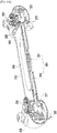
- FIG. 2A is a perspective view illustrating a top surface 210a of an auxiliary control electronic device 200 (alternatively referred to as an "auxiliary electronic controller")according to an embodiment of the disclosure
- FIG. 2B is a diagram illustrating a state in which a mobile terminal 300 is seated in the auxiliary control electronic device 200 of FIG. 2A .
- the auxiliary control electronic device 200 may include a main body 210, first holding portion 220, and second holding portion 230.
- the top surface 210a may mean a surface in which the mobile terminal 300 is seated based on the main body 210
- the bottom surface 210b may mean a surface opposite to the top surface 210a
- a top surface of the first holding portion 220 and the second holding portion 230 may mean a surface positioned in the same direction as that of the top surface based on the main body 210, and a bottom surface thereof may mean a surface opposite to the top surface.
- a direction of the top surface and the bottom surface is not absolute; and, when a direction of any one surface is changed, a direction of the other surface may be also changed corresponding thereto.
- the main body 210 may include a seating portion 240 and a radiating structure formed under the seating portion 240 (not shown in Figures 2A, 2B because of obscuring by the 240, but shown in FIG. 5B , 250).
- the radiating structure under the seating portion be used to radiate heat from a mobile terminal seated in the seating portion 240.
- the seating portion 240 is a space in which the mobile terminal 300 may be seated and may be formed at the top surface of the main body 210.
- the seating portion 240 may be formed to correspond to a size of the mobile terminal 300.
- the mobile terminal 300 may be seated in the seating portion 240 using a separate adapter (not illustrated).
- the separate adapter can be a ring-like structure in a shape and size corresponding to the seating portion 240 and having an opening corresponding to the mobile terminal 300 having a smaller size.
- an internal space may be formed under the seating portion 240.
- a radiating structure may be formed to dissipate heat formed by the mobile terminal 300.
- a front opening 211 may be formed to connect an outer space of the top surface 210a side of the main body 210 and an internal space of the main body 210.
- a radiating structure may be disposed under the seating portion 240, and one surface of a heat sink (obscured by the seating portion 240, but see Figure 5B , 251) disposed under the seating portion 240 may contact the mobile terminal 300 seated in the seating portion 240 through the front opening 211.
- a thermal conductive sheet 255 may be attached to correspond to the size of the front opening 211, and the thermal conductive sheet 255 may contact the mobile terminal 300.
- the heat sink 251 may be disposed directly under the conductive sheet 255.
- the first holding portion 220 may be formed at one side corner of the main body 210 and may include a first control panel 223 (which, in certain embodiments, can comprise physical direction keys and a joystick), first communication interface 226, and second communication interface 227.
- first control panel 223 which, in certain embodiments, can comprise physical direction keys and a joystick
- first communication interface 226, and second communication interface 227 may be formed at one side corner of the main body 210 and may include a first control panel 223 (which, in certain embodiments, can comprise physical direction keys and a joystick), first communication interface 226, and second communication interface 227.
- the first holding portion 220 is a portion which is formed to accommodate a user grip or hold when using the auxiliary control electronic device 200 and may have a thickness larger than that of the main body 210.
- the first holding portion 220 may have an internal space therein, and a first ventilation fan to be described later (see Figure 4C , 222), a battery (not illustrated), and an eccentric motor (not illustrated) may be disposed in the internal space.
- the first control panel 223 may be positioned at the center of one side corner of the main body 210 and be formed at a top surface of the first holding portion 220.
- a position of the first control panel 223 may correspond to a position in which a user's thumb is easily positioned in a state in which the user holds the first holding portion 220.
- the first control panel 223 may maintain a predetermined distance from the top surface of the main body 210 in the first holding portion 220 and protrude in a direction of the main body 210.
- a vertical distance between the protruding portion of the first control panel 223 and a top surface of the main body 210 may correspond to a thickness of the mobile terminal 300. As part of the mobile terminal 300 is inserted between the protruding portion of the first control panel 223 and the main body 210, a coupling state of the mobile terminal 300 and the auxiliary control electronic device 200 may be more secure.
- the first communication interface 226 may be formed in a wall surface of a connected portion of the first holding portion 220 and the main body 210; and, more specifically, the first communication interface 226 may be formed in a space between the first control panel 223 and the top surface of the main body 210.
- the first communication interface 226 may be, for example, a universal serial bus (USB) terminal.
- the first communication interface 226 may be coupled to the mobile terminal 300 in a process in which the mobile terminal 300 is inserted into a space between the protruding portion of the first control panel 223 and the top surface of the main body 210.
- the mobile terminal 300 may be connected to the first communication interface 226 to communicate with the auxiliary control electronic device 200, thereby transferring control signals of the first control panel 223 and a second control panel 233 and a fourth control panel 234 to be described later to the mobile terminal 300.
- the second control panel 224 and the fourth control panel 234 can comprise a trigger key.
- the first communication interface 226 may use a wireless communication method such as Bluetooth or Wi-Fi. Because the mobile terminal 300 mounted in the auxiliary control electronic device 200 is small, when an adapter is used, it may be difficult for the mobile terminal 300 to be connected to the USB terminal, and when the USB terminal is in an unavailable state, the mobile terminal 300 and the auxiliary control electronic device 200 may be connected with a wireless communication method.
- a wireless communication method such as Bluetooth or Wi-Fi.
- a battery (not illustrated) according to an embodiment of the disclosure may be disposed in the first holding portion 220 or the second holding portion 230 or at both the first holding portion 220 and the second holding portion 230, and provide power to the mobile terminal 300 through the first communication interface 226. Further, the battery may supply power to a first ventilation fan 222 disposed in the first holding portion 220 and/or a second ventilation fan (obscured by 230, but see FIG. 4A , 232) to be described later.
- the second communication interface 227 may be formed in the first holding portion 220 and be connected to the first communication interface 226 and the battery.
- the second communication interface 227 may be, for example, a port for inserting a USB terminal and receive power from the outside to charge the battery, and perform a data communication port function for connecting the mobile terminal 300 to another external device.
- the second communication interface 227 may be positioned at the lower end of the first holding portion 220 to be disposed at a position that would not generally be covered by a user's hand when holding the first holding portion 220. This can include the side of the lower end of the first holding portion 220.
- the second holding portion 230 may be formed at the other side corner of the main body 210 and include a second control panel 233.
- the second holding portion 230 is shaped to accommodate a user grip when using the auxiliary control electronic device 200, and may be formed of a thickness larger than that of the main body 210.
- the second holding portion 230 may have an internal space therein and a second ventilation fan 232 to be described later, a battery (not illustrated), and an eccentric motor (not illustrated) may be disposed in the internal space.
- the second holding portion 230 is formed at the other side corner of the main body 210, but it may be hinge-coupled to the main body 210 to rotate within a predetermined range.
- the second holding portion 230 may be bent and rotate in a rear direction of the main body 210 in a state coupled to the main body 210, as in the first holding portion 220.
- a state in which the second holding portion 230 is coupled to the main body 210, as in the first holding portion 220 it is referred to as a fixed state; and a state in which the second holding portion 230 is bent and rotates in a rear direction of the main body 210 may be referred to as an opening state.
- a range in which the second holding portion 230 rotates in the opening state may be a range that avoids interference with a mobile terminal 300 seated in the seating portion 240 of the main body 210 by a rotation of the second holding portion 230.
- the second holding portion 230 can be shaped such that when rotated about the hinge, no portion of the second holding portion 230 collides with the space occupied by the mobile terminal 300.
- the second control panel 233 may be positioned at the center of the other side corner of the main body 210 and be formed at a top surface of the second holding portion 230.
- a position of the second control panel 233 may correspond to a position proximate to the location of a user's thumb, when the user holds the second holding portion 230.
- the second control panel 233 may maintain a predetermined distance from the top surface of the main body 210 in the second holding portion 230 based on a fixed state of the second holding portion 230 and be protruded in a direction of the main body 210.
- a distance between the second holding portion 230 and the top surface of the main body 210 may correspond to a thickness of the mobile terminal 300.
- the second holding portion 230 After the mobile terminal 300 is seated in the seating portion 240, by rotating the second holding portion 230 in a front direction of the main body 210, the second holding portion 230 may be changed to a fixed state; and, as the mobile terminal 300 is inserted between the second control panel 233 of the second holding portion 230 and the main body 210, a coupling state of the mobile terminal 300 and the auxiliary control electronic device 200 may be more secured.
- FIG. 3A is a diagram illustrating a lower portion of a bottom surface of the auxiliary control electronic device 200 according to an embodiment of the disclosure
- FIG. 3B is a diagram illustrating an upper portion of a bottom surface of the auxiliary control electronic device 200 according to an embodiment of the disclosure.
- a rear opening 213 may be formed at a bottom surface of the main body 210 according to an embodiment of the disclosure.
- the rear opening 213 may connect an internal space of the main body 210 to the outside of the main body 210. Air supplied by the first ventilation fan disposed inside the first holding portion 220 or the second ventilation fan 232 disposed inside the second holding portion 230 may flow along radiation fins 253 of the radiating structure under the seating portion 240 and be discharged to the rear opening 213.
- a third control panel 224 may be formed.
- the third control panel 224 may be disposed to protrude from the bottom surface of the first holding portion 220 in a state close to the upper end of the bottom surface of the first holding portion 220.
- the protruded third control panel 224 may elastically rotate using one side corner as a rotation axis, like a trigger. When an external force operates, the third control panel 224 may be inserted into the first holding portion 220; and, when the external force is removed, the third control panel 224 may be protruded to the bottom surface of the first holding portion 220.
- the third control panel 224 may be inserted into the first holding portion 220 only when an external force operates that is larger than the sum of a load of the auxiliary control electronic device 200 and a load of the mobile terminal 300 mounted in the auxiliary control electronic device 200. Accordingly, the auxiliary control electronic device 200 may be used as a cradle.
- the auxiliary control electronic device 200 may be used as a cradle.
- the auxiliary control electronic device 200 may be used as a cradle by adjusting a point at which the third control panel 224 contacts a bottom surface in order to support the auxiliary control electronic device 200 and a protruding angle of the third control panel 224 so that a position of a rotation axis of the third control panel 224 is perpendicular to the bottom surface.
- a fourth control panel 234 may be formed.
- the fourth control panel 234 may be disposed to protrude from the bottom surface of the second holding portion 230 in a state close to the upper end of the bottom surface of the second holding portion 230.
- the protruded fourth control panel 234 may rotate elastically using one side corner as the rotation axis.
- the fourth control panel 234 may be inserted into the second holding portion 230; and, when an external force is removed, the fourth control panel 234 may be protruded to the bottom surface of the second holding portion 230.
- the fourth control panel 234 may be inserted into the second holding portion 230 only when an external force operates that is larger than the sum of a load of the auxiliary control electronic device 200 and a load of the mobile terminal 300 mounted in the auxiliary control electronic device 200.
- the auxiliary control electronic device 200 may be used as a cradle.
- the auxiliary control electronic device 200 may be used as a cradle by adjusting a point at which the fourth control panel 234 contacts a bottom surface in order to support the auxiliary control electronic device 200 and a protruding angle of the fourth control panel 234 so that a position of a rotation axis of the fourth control panel 234 is perpendicular to the bottom surface.
- a third communication interface 236 may be formed.
- the third communication interface 236 may be a port for inserting, for example, an earphone plug for voice communication (microphone and/or speaker).
- the third communication interface 236 may be positioned at the low end of the second holding portion 230 to be disposed so as not to be covered by the hands of the user when holding the second holding portion 230.
- a position of the third communication interface 236 is not limited to the low end of the second holding portion 230 and may be positioned at any position so as not to be covered by the user's hands when the user holds the second holding portion 230.
- a position of the first communications interface 226 to the third communication interface 236 according to an embodiment of the disclosure may be elsewhere in the first holding portion 220 or the second holding portion 230.
- FIGS. 4A to 4C are diagrams illustrating a process of inserting a mobile terminal 300 into an auxiliary control electronic device 200 taken along line A-A of FIG. 2A .
- FIG. 4A is a diagram illustrating the second holding portion 230 in a fixed state
- FIG. 4B is a diagram illustrating the second holding portion 230 in an opening state
- FIG. 4C is a diagram illustrating the mobile terminal 300 seated in the seating portion 240.
- a first vent 215 and/or a second vent 217 may be formed.
- the first vent 215 may connect an internal space of the first holding portion 230 and an internal space of the main body 210
- the second vent 217 may connect an internal space of the second holding portion 230 and an internal space of the main body 210.
- a radiating structure 250 may be disposed.
- the radiating structure 250 may include a heat sink 251 and radiation fins 253.
- One surface of the heat sink 251 may contact the mobile terminal 300 through the front opening 211 of the main body 210.
- a heat generated in the mobile terminal 300 may be transferred to the heat sink 251 to be diffused into the radiating fins 253 and be cooled by air supplied by the first ventilation fan 222 and the second ventilation fan 232.
- a heat conductive sheet 255 may be attached to one surface of the heat sink 251, which may increase heat transfer efficiency from the mobile terminal 300 to the heat sink 251.
- the radiating fins 253 may be disposed at the other surface of the heat sink 251 according to an embodiment of the disclosure and be disposed side by side in a direction of the air-flow created by the first vent 215 and the second vent 217.
- the radiating fins 253 may be disposed side by side in a lateral direction based on a state illustrated in FIG. 4A .
- the center of the heat sink 251 may be formed to protrude further than an end portion positioned toward the first holding portion 220 and the second holding portion 230 of the heat sink 251.
- the protruding portion may correspond to a position of the rear opening 213 of the main body 210.
- the protruding portion may guide to discharge wind supplied from the first vent 215 and the second vent 217 to the rear opening 213 via the radiation fins 253.
- the protruding portion of the first control panel 223 may maintain a predetermined vertical distance from the top surface of the main body 210 in the first holding portion 220 and protrude in a direction of the main body 210.
- the vertical distance between the first control panel 223 and the top surface of the main body 210 may correspond to a thickness of the mobile terminal 300.
- the second control panel 233 may maintain a predetermined distance from the top surface of the main body 210 in the second holding portion 230 and may protrude in a direction of the main body 210.
- a vertical distance between the a protruding portion of the second control panel 233 and the top surface of the main body 210 may correspond to a thickness of the mobile terminal 300.
- the first holding portion 220 may have an internal space therein and include at least one of a first ventilation fan 222, an eccentric motor or a battery.
- the first ventilation fan 222 may blow air to an internal space of the main body 210 through the first vent 215.
- the supplied air may flow along the radiation fins 253 and be discharged through the rear opening 213.
- the eccentric motor may operate according to a manipulation of the mobile terminal 300 to transfer a vibration to the user through the first holding portion 220.
- the battery according to an embodiment of the disclosure may supply power to the mobile terminal 300 through the first communication interface 226.
- the battery may supply power for an operation of the first ventilation fan 222.
- the second holding portion 230 may have an internal space therein and include at least one of a second ventilation fan 232, an eccentric motor or a battery.
- the second ventilation fan 232 may blow air to an internal space of the main body 210 through the second vents 217.
- the air flow along the radiation fins 253 can be discharged through the rear opening 213.
- the eccentric motor may operate according to a manipulation of the mobile terminal 300 to transfer a vibration to the user through the second holding portion 230.
- the battery according to an embodiment of the disclosure may be electrically connected to the first communication interface 226 to supply power to the mobile terminal 300.
- the battery may be connected to the first communication interface 226 by various methods and be connected through, for example, a flexible printed circuit board (FPCB).
- the battery may supply power for an operation of the second ventilation fan 232.
- FIGS. 5A to 5C are diagrams illustrating the radiating structure 250 of the auxiliary control electronic device 200 according to an embodiment of the disclosure.
- FIG. 5A is a cross-sectional view illustrating the auxiliary control electronic device 200 in which the mobile terminal 300 is seated;
- FIG. 5B is a diagram illustrating a bottom surface of the first holding portion 220, a bottom surface of the main body 210, and the radiating structure 250;
- FIG. 5C is a diagram illustrating the heat sink 251 and the radiation fins 253.
- One surface of the heat sink 251 may contact the mobile terminal 300 through the front opening 211 of the main body 210.
- the heat conductive sheet 255 may be attached to one surface of the heat sink 251, which may increase heat transfer efficiency between the mobile terminal 300 and the heat sink 251.
- the radiating fins 253 may be disposed to the other surface of the heat sink 251 according to an embodiment of the disclosure and be disposed side by side in a direction of the air-flow establish by the first vent 215 and the second vent 217.
- a central portion of the heat sink 251 may protrude further than an end portion positioned towards the first holding portion 220 and the second holding portion 230 of the heat sink 251.
- the protruding portion may correspond to a position of the rear opening 213 of the main body 210.
- the protruding portion may be guided so that the air-flow established by the first vent 215 and the second vent 217 is discharged to the rear opening 213 via the radiation fins 253.
- a height (or thickness) of the radiating fins 253 gradually lowers as they approach the center of the heat sink 251; thus, a height of an end portion of the radiating fins 253 may be formed to be uniform over the entire heat sink 251.
- FIGS 6A and 6B are diagrams illustrating the radiating fins 253 and the heat sink 251 according to an embodiment of the disclosure.
- the heat sink 251 and the radiation fins 253 may protrude in a front direction of the main body 210 at an internal space of the main body 210 or may be inserted towards the bottom of the main body 210.
- an elastic member 257 disposed between a bottom surface of the main body 210 and the heat sink 251 may press the heat sink 251 to the top surface of the main body 210.
- the mobile terminal 300 is seated in the seating portion 240 of the main body 210, one surface of the heat sink 251 is pressed; thus, the heat sink 251 may be inserted into an internal space of the main body 210.
- the elastic member 257 presses the heat sink 251 close contact of the mobile terminal 300 (seated in the seating portion 240) and the heat sink 251 may be maintained.
- FIGS. 7A to 7C are diagrams illustrating a process of inserting the mobile terminal 300 into the auxiliary control electronic device 200 according to an embodiment of the disclosure.
- the second holding portion 230 As illustrated in FIG. 7A , by bending and rotating the second holding portion 230 of a fixed state to a bottom surface of the main body 210, as illustrated in FIG. 7B , the second holding portion 230 is in an opening state, and by sliding the mobile terminal 300 to the seating portion 240, the mobile terminal 300 may be fitted and coupled between the first control panel 223 and the main body 210. By rotating again the second holding portion 230 in a front direction of the main body 210, the second holding portion 230 is in a fixed state; thus, the mobile terminal 300 may be fixed by the second control panel 233.
- a process of separating the mobile terminal 300 may be performed in the reverse order of the above-described process.
- the second holding portion 230 By bending and rotating the second holding portion 230 in a fixed state to a bottom surface of the main body 210, the second holding portion 230 is in an opening state, by performing a sliding movement of the mobile terminal 300, the mobile terminal 300 is separated, and by rotating the second holding portion 230 to the top surface of the main body 210, the second holding portion 230 is in a fixed state; thus, the mobile terminal 300 may be separated.
- FIG. 8 is a diagram illustrating a state of supporting the auxiliary control electronic device 200 according to an embodiment of the disclosure.
- the third control panel 224 and the fourth control panel 234 may be formed at a bottom surface of the first holding portion 220 and a bottom surface of the second holding portion 230, respectively.
- the third control panel 224 may be disposed to protrude from the bottom surface of the first holding portion 220 in a state close to the upper end of the bottom surface of the first holding portion 220
- the fourth control panel 234 may be disposed to protrude from the bottom surface of the second holding portion 230 in a state close to the upper end of the bottom surface of the second holding portion 230.
- the third control panel 224 and the fourth control panel 234 may be inserted into the first holding portion 220 or the second holding portion 230 only when an external force operates that is larger than the sum of a load of the auxiliary control electronic device 200 and a load of the mobile terminal 300 mounted in the auxiliary control electronic device 200. Therefore, the auxiliary control electronic device 200 may be used as a cradle of the mobile terminal 300 by using the third control panel 224 and the fourth control panel 234, as illustrated in FIG. 8 .
- the auxiliary control electronic device 200 of the mobile terminal 300 may include a main body 210 having a seating portion 240 configured to seat the mobile terminal 300 at a top surface and having a radiating structure 250 therein; a first holding portion 220 formed at one side corner of the main body 210; and a second holding portion 230 hinge-coupled to the other side corner facing one side corner of the main body 210 to rotate to a bottom surface of the main body 210.
- the main body 210 may have an internal space therein, and a front opening 211 and a rear opening 213 may be formed at the top surface and the bottom surface, respectively, to enable the outside of the main body 210 and the internal space to be connected.
- the first holding portion 220 may have an internal space therein and be connected to an internal space through a first vent 215 formed in one side corner of the main body 210
- the second holding portion 230 may have an internal space therein and be connected to the internal space through a second vent 217 formed in the other side corner of the main body 210.
- the radiating structure 250 may include a heat sink 251 disposed at an internal space of the main body 210 and having one surface contacting the mobile terminal seated in the seating portion 240 through the front opening 211 and radiating fins 253 disposed at the other surface of the heat sink 251 and formed side by side in a direction of the first holding portion 220 and the second holding portion 230.
- the other surface of the heat sink 251 may be formed to protrude towards the center from an end portion of the first holding portion 220 side and an end portion of the second holding portion 230 side.
- a first ventilation fan 222 may be disposed at the internal space of the first holding portion 220, and the first ventilation fan 222 may supply air to the internal space of the main body 210 through the first vent 215; and a second ventilation fan 232 may be disposed in the internal space of the second holding portion 230, and the second ventilation fan 232 may supply air to the internal space of the main body 210 through the second vent 217.
- a height of the radiating fins 253 may be formed to be lower as they advance to the center from an end portion of the first holding portion 220 side and an end portion of the second holding portion 230 side to enable the radiating fins 253 protruded from the heat sink 251 to have a uniform height.
- a thermal conductive sheet 255 may be disposed to correspond to the front opening 211 of the main body 210.
- the auxiliary control electronic device may further include an elastic member 257 disposed between the heat sink 251 and the bottom surface of the main body 210 and configured to press the heat sink 251 to the top surface of the main body 210.
- the auxiliary control electronic device may further include a first control panel 223 disposed at a top surface of the first holding portion 220 and disposed at a position of the center of one side corner of the main body 210 and a second control panel 233 disposed at a top surface of the second holding portion 230 and disposed at a position of the center of the other side corner of the main body 210, wherein the first control panel 223 and the second control panel 233 may be partially protruded towards the main body 210 to be overlapped by a predetermined distance in a front direction of the main body 210.
- the auxiliary control electronic device may further include a third control panel 224 disposed to protrude from a bottom surface of the first holding portion 220 at the upper end of the bottom surface of the first holding portion 220, configured to elastically rotate using one side corner as a rotation axis, inserted into the first holding portion 220 when an external force operates, and protruded to the bottom surface of the first holding portion 220 when an external force is removed; and a fourth control panel 234 disposed to protrude from the bottom surface of the second holding portion 230 at the upper end of the bottom surface of the second holding portion 230, configured to rotate elastically using one side corner as a rotation axis, inserted into the second holding portion 230 when an external force operates, and protruded to the bottom surface of the second holding portion 230 when an external force is removed.
- a third control panel 224 disposed to protrude from a bottom surface of the first holding portion 220 at the upper end of the bottom surface of the first holding portion 220, configured to elastically rotate using one side corner as
- An eccentric motor may be disposed at the internal space of the first holding portion 220 or the internal space of the second holding portion 230.
- the auxiliary control electronic device may further include a battery configured to supply power to the first ventilation fan 222 and the second ventilation fan 232 at an internal space of the first holding portion 220 and an internal space of the second holding portion 230.
- the battery may supply power to the mobile terminal seated in the seating portion 240.
- the auxiliary control electronic device may further include a first communication interface 226 disposed in the first holding portion 220 to be connected to the mobile terminal.
- the auxiliary control electronic device may further include a second communication interface 227 disposed in the first holding portion 220 and electrically connected to the battery and the first communication interface 226.
- the auxiliary control electronic device may further include a third communication interface 236 disposed in the second holding portion 230 and electrically connected to the first communication interface 226.
- the mobile terminal when manipulating the mobile terminal with the auxiliary control electronic device, the mobile terminal can be manipulated elaborately and conveniently; and, even though the mobile terminal is used for a long time, a performance deterioration problem caused by power shortage and heat generation can be prevented.
- auxiliary control electronic device can perform a function of a cradle that can support the mobile terminal.
Landscapes
- Engineering & Computer Science (AREA)
- Multimedia (AREA)
- Theoretical Computer Science (AREA)
- Physics & Mathematics (AREA)
- Microelectronics & Electronic Packaging (AREA)
- Human Computer Interaction (AREA)
- Computer Hardware Design (AREA)
- Thermal Sciences (AREA)
- General Physics & Mathematics (AREA)
- General Engineering & Computer Science (AREA)
- Power Engineering (AREA)
- Computer Networks & Wireless Communication (AREA)
- Signal Processing (AREA)
- Telephone Set Structure (AREA)
- Telephone Function (AREA)
Description
- The disclosure relates to an auxiliary control device capable of supporting a mobile terminal while enabling the mobile terminal to be manipulated more freely and conveniently.
- Mobile terminals may perform various functions in a complex manner, thereby producing a high performance in order to realize an advanced performance. As an input means of the mobile terminal, a touch screen may be mainly used.
-
US2015/174482 discloses a game controller for use with handheld game devices, which includes a cradle for holding the smartphone. The cradle is pivotable between an open position, extending from a base of the game controller, and a closed position in which the cradle is about a bottom wall of the base. -
US2016/107082 discloses a game controller device including an assembling component and at least one input module. The at least one input module is movably connected to a side of the assembling component to have a first using position and a second using position. -
US2015/031452 discloses a game controller assembly which is mechanically and communicatively connected to a user computing device to be used to play games. The game controller assembly is detachably coupled mechanically and electrically to the user computing device. - With a touch screen, which is a primary input means of the mobile terminal, it may be difficult or inconvenient to perform an elaborate manipulation when using a particular application.
- The above information is presented as background information only to assist with an understanding of the present disclosure. No determination has been made, and no assertion is made, as to whether any of the above might be applicable as prior art with regard to the present disclosure.
- In accordance with an aspect of the disclosure, an auxiliary electronic controller of a mobile terminal according to claim 1 is provided.
- The disclosure provides an auxiliary control device that can be manipulated elaborately and conveniently when a mobile terminal is manipulated.
- The disclosure further provides an auxiliary control device that can solve a power shortage problem and a performance deterioration problem caused by heat generation that may occur in a process of using a mobile terminal.
- The objects, features, and advantages of the disclosure will be more apparent from the following detailed description in conjunction with the accompanying drawings, in which:
-
FIG. 1 is a block diagram illustrating an electronic device in a network environment according to certain embodiments of the disclosure; -
FIGS. 2A and 2B are front perspective views illustrating an auxiliary control electronic device according to an embodiment of the disclosure; -
FIGS. 3A and 3B are rear perspective views illustrating an auxiliary control electronic device according to an embodiment of the disclosure; -
FIGS. 4A to 4C are diagrams illustrating a process of inserting a mobile terminal into an auxiliary control electronic device taken along line A-A ofFIG. 2A ; -
FIGS. 5A to 5C are diagrams illustrating a radiating structure of an auxiliary control electronic device according to an embodiment of the disclosure; -
FIGS. 6A and6B are diagrams illustrating radiating fins and a radiating plate according to an embodiment of the disclosure; -
FIGS. 7A to 7C are diagrams illustrating a process of inserting a mobile terminal into an auxiliary control electronic device according to an embodiment of the disclosure; and -
FIG. 8 is a diagram illustrating a support state of an auxiliary control electronic device according to an embodiment of the disclosure. -
Fig. 1 is a block diagram illustrating anelectronic device 101 in anetwork environment 100 according to certain embodiments. Referring toFig. 1 , theelectronic device 101 in thenetwork environment 100 may communicate with anelectronic device 102 via a first network 198 (e.g., a short-range wireless communication network), or anelectronic device 104 or aserver 108 via a second network 199 (e.g., a long-range wireless communication network). According to an embodiment, theelectronic device 101 may communicate with theelectronic device 104 via theserver 108. According to an embodiment, theelectronic device 101 may include aprocessor 120,memory 130, aninput device 150, asound output device 155, adisplay device 160, anaudio module 170, asensor module 176, aninterface 177, ahaptic module 179, acamera module 180, apower management module 188, abattery 189, acommunication module 190, a subscriber identification module (SIM) 196, or anantenna module 197. In some embodiments, at least one (e.g., thedisplay device 160 or the camera module 180) of the components may be omitted from theelectronic device 101, or one or more other components may be added in theelectronic device 101. In some embodiments, some of the components may be implemented as single integrated circuitry. For example, the sensor module 176 (e.g., a fingerprint sensor, an iris sensor, or an illuminance sensor) may be implemented as embedded in the display device 160 (e.g., a display). - The
processor 120 may execute, for example, software (e.g., a program 140) to control at least one other component (e.g., a hardware or software component) of theelectronic device 101 coupled with theprocessor 120, and may perform various data processing or computation. According to one embodiment, as at least part of the data processing or computation, theprocessor 120 may load a command or data received from another component (e.g., thesensor module 176 or the communication module 190) involatile memory 132, process the command or the data stored in thevolatile memory 132, and store resulting data innon-volatile memory 134. According to an embodiment, theprocessor 120 may include a main processor 121 (e.g., a central processing unit (CPU) or an application processor (AP)), and an auxiliary processor 123 (e.g., a graphics processing unit (GPU), an image signal processor (ISP), a sensor hub processor, or a communication processor (CP)) that is operable independently from, or in conjunction with, themain processor 121. Additionally or alternatively, theauxiliary processor 123 may be adapted to consume less power than themain processor 121, or to be specific to a specified function. Theauxiliary processor 123 may be implemented as separate from, or as part of themain processor 121. - The
auxiliary processor 123 may control at least some of functions or states related to at least one component (e.g., thedisplay device 160, thesensor module 176, or the communication module 190) among the components of theelectronic device 101, instead of themain processor 121 while themain processor 121 is in an inactive (e.g., sleep) state, or together with themain processor 121 while themain processor 121 is in an active state (e.g., executing an application). According to an embodiment, the auxiliary processor 123 (e.g., an image signal processor or a communication processor) may be implemented as part of another component (e.g., thecamera module 180 or the communication module 190) functionally related to theauxiliary processor 123. - The
memory 130 may store various data used by at least one component (e.g., theprocessor 120 or the sensor module 176) of theelectronic device 101. The various data may include, for example, software (e.g., the program 140) and input data or output data for a command related thererto. Thememory 130 may include thevolatile memory 132 or thenon-volatile memory 134. - The
program 140 may be stored in thememory 130 as software, and may include, for example, an operating system (OS) 142,middleware 144, or anapplication 146. - The
input device 150 may receive a command or data to be used by other component (e.g., the processor 120) of theelectronic device 101, from the outside (e.g., a user) of theelectronic device 101. Theinput device 150 may include, for example, a microphone, a mouse, or a keyboard. - The
sound output device 155 may output sound signals to the outside of theelectronic device 101. Thesound output device 155 may include, for example, a speaker or a receiver. The speaker may be used for general purposes, such as playing multimedia or playing record, and the receiver may be used for an incoming calls. According to an embodiment, the receiver may be implemented as separate from, or as part of the speaker. - The
display device 160 may visually provide information to the outside (e.g., a user) of theelectronic device 101. Thedisplay device 160 may include, for example, a display, a hologram device, or a projector and control circuitry to control a corresponding one of the display, hologram device, and projector. According to an embodiment, thedisplay device 160 may include touch circuitry adapted to detect a touch, or sensor circuitry (e.g., a pressure sensor) adapted to measure the intensity of force incurred by the touch. - The
audio module 170 may convert a sound into an electrical signal and vice versa. According to an embodiment, theaudio module 170 may obtain the sound via theinput device 150, or output the sound via thesound output device 155 or a headphone of an external electronic device (e.g., an electronic device 102) directly (e.g., wiredly) or wirelessly coupled with theelectronic device 101. - The
sensor module 176 may detect an operational state (e.g., power or temperature) of theelectronic device 101 or an environmental state (e.g., a state of a user) external to theelectronic device 101, and then generate an electrical signal or data value corresponding to the detected state. According to an embodiment, thesensor module 176 may include, for example, a gesture sensor, a gyro sensor, an atmospheric pressure sensor, a magnetic sensor, an acceleration sensor, a grip sensor, a proximity sensor, a color sensor, an infrared (IR) sensor, a biometric sensor, a temperature sensor, a humidity sensor, or an illuminance sensor. - The
interface 177 may support one or more specified protocols to be used for theelectronic device 101 to be coupled with the external electronic device (e.g., the electronic device 102) directly (e.g., wiredly) or wirelessly. According to an embodiment, theinterface 177 may include, for example, a high definition multimedia interface (HDMI), a universal serial bus (USB) interface, a secure digital (SD) card interface, or an audio interface. - A connecting
terminal 178 may include a connector via which theelectronic device 101 may be physically connected with the external electronic device (e.g., the electronic device 102). According to an embodiment, the connectingterminal 178 may include, for example, a HDMI connector, a USB connector, a SD card connector, or an audio connector (e.g., a headphone connector), - The
haptic module 179 may convert an electrical signal into a mechanical stimulus (e.g., a vibration or a movement) or electrical stimulus which may be recognized by a user via his tactile sensation or kinesthetic sensation. According to an embodiment, thehaptic module 179 may include, for example, a motor, a piezoelectric element, or an electric stimulator. - The
camera module 180 may capture a still image or moving images. According to an embodiment, thecamera module 180 may include one or more lenses, image sensors, image signal processors, or flashes. - The
power management module 188 may manage power supplied to theelectronic device 101. According to one embodiment, thepower management module 188 may be implemented as at least part of, for example, a power management integrated circuit (PMIC). - The
battery 189 may supply power to at least one component of theelectronic device 101. According to an embodiment, thebattery 189 may include, for example, a primary cell which is not rechargeable, a secondary cell which is rechargeable, or a fuel cell. - The
communication module 190 may support establishing a direct (e.g., wired) communication channel or a wireless communication channel between theelectronic device 101 and the external electronic device (e.g., theelectronic device 102, theelectronic device 104, or the server 108) and performing communication via the established communication channel. Thecommunication module 190 may include one or more communication processors that are operable independently from the processor 120 (e.g., the application processor (AP)) and supports a direct (e.g., wired) communication or a wireless communication. According to an embodiment, thecommunication module 190 may include a wireless communication module 192 (e.g., a cellular communication module, a short-range wireless communication module, or a global navigation satellite system (GNSS) communication module) or a wired communication module 194 (e.g., a local area network (LAN) communication module or a power line communication (PLC) module). A corresponding one of these communication modules may communicate with the external electronic device via the first network 198 (e.g., a short-range communication network, such as BluetoothTM, wireless-fidelity (Wi-Fi) direct, or infrared data association (IrDA)) or the second network 199 (e.g., a long-range communication network, such as a cellular network, the Internet, or a computer network (e.g., LAN or wide area network (WAN)). These various types of communication modules may be implemented as a single component (e.g., a single chip), or may be implemented as multi components (e.g., multi chips) separate from each other. Thewireless communication module 192 may identify and authenticate theelectronic device 101 in a communication network, such as thefirst network 198 or thesecond network 199, using subscriber information (e.g., international mobile subscriber identity (IMSI)) stored in thesubscriber identification module 196. - The
antenna module 197 may transmit or receive a signal or power to or from the outside (e.g., the external electronic device) of theelectronic device 101. According to an embodiment, theantenna module 197 may include one or more antennas, and, therefrom, at least one antenna appropriate for a communication scheme used in the communication network, such as thefirst network 198 or thesecond network 199, may be selected, for example, by the communication module 190 (e.g., the wireless communication module 192). The signal or the power may then be transmitted or received between thecommunication module 190 and the external electronic device via the selected at least one antenna. - At least some of the above-described components may be coupled mutually and communicate signals (e.g., commands or data) therebetween via an inter-peripheral communication scheme (e.g., a bus, general purpose input and output (GPIO), serial peripheral interface (SPI), or mobile industry processor interface (MIPI)).
- According to an embodiment, commands or data may be transmitted or received between the
electronic device 101 and the externalelectronic device 104 via theserver 108 coupled with thesecond network 199. Each of theelectronic devices electronic device 101. According to an embodiment, all or some of operations to be executed at theelectronic device 101 may be executed at one or more of the externalelectronic devices electronic device 101 should perform a function or a service automatically, or in response to a request from a user or another device, theelectronic device 101, instead of, or in addition to, executing the function or the service, may request the one or more external electronic devices to perform at least part of the function or the service. The one or more external electronic devices receiving the request may perform the at least part of the function or the service requested, or an additional function or an additional service related to the request, and transfer an outcome of the performing to theelectronic device 101. Theelectronic device 101 may provide the outcome, with or without further processing of the outcome, as at least part of a reply to the request. To that end, a cloud computing, distributed computing, or client-server computing technology may be used, for example. - The electronic device according to certain embodiments may be one of various types of electronic devices. The electronic devices may include, for example, a portable communication device (e.g., a smart phone), a computer device, a portable multimedia device, a portable medical device, a camera, a wearable device, or a home appliance. According to an embodiment of the disclosure, the electronic devices are not limited to those described above.
- It should be appreciated that certain embodiments of the present disclosure and the terms used therein are not intended to limit the technological features set forth herein to particular embodiments and include various changes, equivalents, or replacements for a corresponding embodiment. With regard to the description of the drawings, similar reference numerals may be used to refer to similar or related elements. It is to be understood that a singular form of a noun corresponding to an item may include one or more of the things, unless the relevant context clearly indicates otherwise. As used herein, each of such phrases as "A or B," "at least one of A and B," "at least one of A or B," "A, B, or C," "at least one of A, B, and C," and "at least one of A, B, or C," may include all possible combinations of the items enumerated together in a corresponding one of the phrases. As used herein, such terms as "1st" and "2nd," or "first" and "second" may be used to simply distinguish a corresponding component from another, and does not limit the components in other aspect (e.g., importance or order). It is to be understood that if an element (e.g., a first element) is referred to, with or without the term "operatively" or "communicatively", as "coupled with," "coupled to," "connected with," or "connected to" another element (e.g., a second element), it means that the element may be coupled with the other element directly (e.g., wiredly), wirelessly, or via a third element.
- As used herein, the term "module" may include a unit implemented in hardware, hardware programmed by software, and may interchangeably be used with other terms, for example, "logic," "logic block," "part," or "circuitry". A module may be a single integral component, or a minimum unit or part thereof, adapted to perform one or more functions. For example, according to an embodiment, the module may be implemented in a form of an application-specific integrated circuit (ASIC).
- Certain embodiments as set forth herein may be implemented as software (e.g., the program 140) including one or more instructions that are stored in a storage medium (e.g.,
internal memory 136 or external memory 138) that is readable by a machine (e.g., the electronic device 101). For example, a processor (e.g., the processor 120) of the machine (e.g., the electronic device 101) may invoke at least one of the one or more instructions stored in the storage medium, and execute it, with or without using one or more other components under the control of the processor. This allows the machine to be operated to perform at least one function according to the at least one instruction invoked. The one or more instructions may include a code generated by a complier or a code executable by an interpreter. The machine-readable storage medium may be provided in the form of a non-transitory storage medium. Wherein, the term "non-transitory" simply means that the storage medium is a tangible device, and does not include a signal (e.g., an electromagnetic wave), but this term does not differentiate between where data is semi-permanently stored in the storage medium and where the data is temporarily stored in the storage medium. - According to an embodiment, a method according to certain embodiments of the disclosure may be included and provided in a computer program product. The computer program product may be traded as a product between a seller and a buyer. The computer program product may be distributed in the form of a machine-readable storage medium (e.g., compact disc read only memory (CD-ROM)), or be distributed (e.g., downloaded or uploaded) online via an application store (e.g., Play StoreTM), or between two user devices (e.g., smart phones) directly. If distributed online, at least part of the computer program product may be temporarily generated or at least temporarily stored in the machine-readable storage medium, such as memory of the manufacturer's server, a server of the application store, or a relay server.
- According to certain embodiments, each component (e.g., a module or a program) of the above-described components may include a single entity or multiple entities. According to certain embodiments, one or more of the above-described components may be omitted, or one or more other components may be added. Alternatively or additionally, a plurality of components (e.g., modules or programs) may be integrated into a single component. In such a case, according to certain embodiments, the integrated component may still perform one or more functions of each of the plurality of components in the same or similar manner as they are performed by a corresponding one of the plurality of components before the integration. According to certain embodiments, operations performed by the module, the program, or another component may be carried out sequentially, in parallel, repeatedly, or heuristically, or one or more of the operations may be executed in a different order or omitted, or one or more other operations may be added.
- While the
electronic device 101 ofFigure 1 can be controlled by a touch screen, it would be advantageous to diversify the ways that theelectronic device 101 can be controlled. For example, an auxiliary electronic controller can be used to control the mobile terminal. -
FIG. 2A is a perspective view illustrating atop surface 210a of an auxiliary control electronic device 200 (alternatively referred to as an "auxiliary electronic controller")according to an embodiment of the disclosure, andFIG. 2B is a diagram illustrating a state in which amobile terminal 300 is seated in the auxiliary controlelectronic device 200 ofFIG. 2A . - The auxiliary control
electronic device 200 according to an embodiment of the disclosure may include amain body 210, first holdingportion 220, and second holdingportion 230. - When describing the auxiliary control
electronic device 200 according to an embodiment of the disclosure, thetop surface 210a may mean a surface in which themobile terminal 300 is seated based on themain body 210, and thebottom surface 210b may mean a surface opposite to thetop surface 210a. A top surface of thefirst holding portion 220 and thesecond holding portion 230 may mean a surface positioned in the same direction as that of the top surface based on themain body 210, and a bottom surface thereof may mean a surface opposite to the top surface. When describing themain body 210, thefirst holding portion 220, and thesecond holding portion 230, a direction of the top surface and the bottom surface is not absolute; and, when a direction of any one surface is changed, a direction of the other surface may be also changed corresponding thereto. - The
main body 210 according to an embodiment of the disclosure may include aseating portion 240 and a radiating structure formed under the seating portion 240 (not shown inFigures 2A, 2B because of obscuring by the 240, but shown inFIG. 5B , 250). The radiating structure under the seating portion be used to radiate heat from a mobile terminal seated in theseating portion 240. - The
seating portion 240 according to the embodiment of the disclosure is a space in which themobile terminal 300 may be seated and may be formed at the top surface of themain body 210. Theseating portion 240 may be formed to correspond to a size of themobile terminal 300. When wanting to seat themobile terminal 300 having a size smaller than that of theseating portion 240, themobile terminal 300 may be seated in theseating portion 240 using a separate adapter (not illustrated). - The separate adapter can be a ring-like structure in a shape and size corresponding to the
seating portion 240 and having an opening corresponding to themobile terminal 300 having a smaller size. - In the
main body 210 according to an embodiment of the disclosure, an internal space may be formed under theseating portion 240. In the internal space of themain body 210, a radiating structure may be formed to dissipate heat formed by themobile terminal 300. At a top surface of themain body 210, afront opening 211 may be formed to connect an outer space of thetop surface 210a side of themain body 210 and an internal space of themain body 210. At the internal space of themain body 210, a radiating structure may be disposed under theseating portion 240, and one surface of a heat sink (obscured by theseating portion 240, but seeFigure 5B , 251) disposed under theseating portion 240 may contact themobile terminal 300 seated in theseating portion 240 through thefront opening 211. At one surface of the heat sink, a thermalconductive sheet 255 may be attached to correspond to the size of thefront opening 211, and the thermalconductive sheet 255 may contact themobile terminal 300. In certain embodiments, theheat sink 251 may be disposed directly under theconductive sheet 255. - The
first holding portion 220 according to an embodiment of the disclosure may be formed at one side corner of themain body 210 and may include a first control panel 223 (which, in certain embodiments, can comprise physical direction keys and a joystick),first communication interface 226, andsecond communication interface 227. - The
first holding portion 220 according to an embodiment of the disclosure is a portion which is formed to accommodate a user grip or hold when using the auxiliary controlelectronic device 200 and may have a thickness larger than that of themain body 210. Thefirst holding portion 220 may have an internal space therein, and a first ventilation fan to be described later (seeFigure 4C , 222), a battery (not illustrated), and an eccentric motor (not illustrated) may be disposed in the internal space. - The
first control panel 223 according to an embodiment of the disclosure may be positioned at the center of one side corner of themain body 210 and be formed at a top surface of thefirst holding portion 220. A position of thefirst control panel 223 may correspond to a position in which a user's thumb is easily positioned in a state in which the user holds thefirst holding portion 220. Thefirst control panel 223 may maintain a predetermined distance from the top surface of themain body 210 in thefirst holding portion 220 and protrude in a direction of themain body 210. A vertical distance between the protruding portion of thefirst control panel 223 and a top surface of themain body 210 may correspond to a thickness of themobile terminal 300. As part of themobile terminal 300 is inserted between the protruding portion of thefirst control panel 223 and themain body 210, a coupling state of themobile terminal 300 and the auxiliary controlelectronic device 200 may be more secure. - The
first communication interface 226 according to an embodiment of the disclosure may be formed in a wall surface of a connected portion of thefirst holding portion 220 and themain body 210; and, more specifically, thefirst communication interface 226 may be formed in a space between thefirst control panel 223 and the top surface of themain body 210. Thefirst communication interface 226 may be, for example, a universal serial bus (USB) terminal. Thefirst communication interface 226 may be coupled to themobile terminal 300 in a process in which themobile terminal 300 is inserted into a space between the protruding portion of thefirst control panel 223 and the top surface of themain body 210. Themobile terminal 300 may be connected to thefirst communication interface 226 to communicate with the auxiliary controlelectronic device 200, thereby transferring control signals of thefirst control panel 223 and asecond control panel 233 and afourth control panel 234 to be described later to themobile terminal 300. In certain embodiments, thesecond control panel 224 and thefourth control panel 234 can comprise a trigger key. - The
first communication interface 226 according to an embodiment of the disclosure may use a wireless communication method such as Bluetooth or Wi-Fi. Because themobile terminal 300 mounted in the auxiliary controlelectronic device 200 is small, when an adapter is used, it may be difficult for themobile terminal 300 to be connected to the USB terminal, and when the USB terminal is in an unavailable state, themobile terminal 300 and the auxiliary controlelectronic device 200 may be connected with a wireless communication method. - A battery (not illustrated) according to an embodiment of the disclosure may be disposed in the
first holding portion 220 or thesecond holding portion 230 or at both thefirst holding portion 220 and thesecond holding portion 230, and provide power to themobile terminal 300 through thefirst communication interface 226. Further, the battery may supply power to afirst ventilation fan 222 disposed in thefirst holding portion 220 and/or a second ventilation fan (obscured by 230, but seeFIG. 4A , 232) to be described later. - The
second communication interface 227 according to an embodiment of the disclosure may be formed in thefirst holding portion 220 and be connected to thefirst communication interface 226 and the battery. Thesecond communication interface 227 may be, for example, a port for inserting a USB terminal and receive power from the outside to charge the battery, and perform a data communication port function for connecting themobile terminal 300 to another external device. - The
second communication interface 227 may be positioned at the lower end of thefirst holding portion 220 to be disposed at a position that would not generally be covered by a user's hand when holding thefirst holding portion 220. This can include the side of the lower end of thefirst holding portion 220. - The
second holding portion 230 according to an embodiment of the disclosure may be formed at the other side corner of themain body 210 and include asecond control panel 233. - The
second holding portion 230 according to an embodiment of the disclosure is shaped to accommodate a user grip when using the auxiliary controlelectronic device 200, and may be formed of a thickness larger than that of themain body 210. Thesecond holding portion 230 may have an internal space therein and asecond ventilation fan 232 to be described later, a battery (not illustrated), and an eccentric motor (not illustrated) may be disposed in the internal space. - The
second holding portion 230 according to an embodiment of the disclosure is formed at the other side corner of themain body 210, but it may be hinge-coupled to themain body 210 to rotate within a predetermined range. For example, thesecond holding portion 230 may be bent and rotate in a rear direction of themain body 210 in a state coupled to themain body 210, as in thefirst holding portion 220. When a state in which thesecond holding portion 230 is coupled to themain body 210, as in thefirst holding portion 220, it is referred to as a fixed state; and a state in which thesecond holding portion 230 is bent and rotates in a rear direction of themain body 210 may be referred to as an opening state. A range in which thesecond holding portion 230 rotates in the opening state may be a range that avoids interference with amobile terminal 300 seated in theseating portion 240 of themain body 210 by a rotation of thesecond holding portion 230. Thesecond holding portion 230 can be shaped such that when rotated about the hinge, no portion of thesecond holding portion 230 collides with the space occupied by themobile terminal 300. - The
second control panel 233 according to an embodiment of the disclosure may be positioned at the center of the other side corner of themain body 210 and be formed at a top surface of thesecond holding portion 230. A position of thesecond control panel 233 may correspond to a position proximate to the location of a user's thumb, when the user holds thesecond holding portion 230. Thesecond control panel 233 may maintain a predetermined distance from the top surface of themain body 210 in thesecond holding portion 230 based on a fixed state of thesecond holding portion 230 and be protruded in a direction of themain body 210. A distance between thesecond holding portion 230 and the top surface of themain body 210 may correspond to a thickness of themobile terminal 300. After themobile terminal 300 is seated in theseating portion 240, by rotating thesecond holding portion 230 in a front direction of themain body 210, thesecond holding portion 230 may be changed to a fixed state; and, as themobile terminal 300 is inserted between thesecond control panel 233 of thesecond holding portion 230 and themain body 210, a coupling state of themobile terminal 300 and the auxiliary controlelectronic device 200 may be more secured. -
FIG. 3A is a diagram illustrating a lower portion of a bottom surface of the auxiliary controlelectronic device 200 according to an embodiment of the disclosure, andFIG. 3B is a diagram illustrating an upper portion of a bottom surface of the auxiliary controlelectronic device 200 according to an embodiment of the disclosure. - At a bottom surface of the
main body 210 according to an embodiment of the disclosure, arear opening 213 may be formed. Therear opening 213 may connect an internal space of themain body 210 to the outside of themain body 210. Air supplied by the first ventilation fan disposed inside thefirst holding portion 220 or thesecond ventilation fan 232 disposed inside thesecond holding portion 230 may flow alongradiation fins 253 of the radiating structure under theseating portion 240 and be discharged to therear opening 213. - At a bottom surface of the
first holding portion 220 according to an embodiment of the disclosure, athird control panel 224 may be formed. Thethird control panel 224 may be disposed to protrude from the bottom surface of thefirst holding portion 220 in a state close to the upper end of the bottom surface of thefirst holding portion 220. The protrudedthird control panel 224 may elastically rotate using one side corner as a rotation axis, like a trigger. When an external force operates, thethird control panel 224 may be inserted into thefirst holding portion 220; and, when the external force is removed, thethird control panel 224 may be protruded to the bottom surface of thefirst holding portion 220. Thethird control panel 224 may be inserted into thefirst holding portion 220 only when an external force operates that is larger than the sum of a load of the auxiliary controlelectronic device 200 and a load of themobile terminal 300 mounted in the auxiliary controlelectronic device 200. Accordingly, the auxiliary controlelectronic device 200 may be used as a cradle. - Alternatively, by adjusting a protruding angle of the
third control panel 224, the auxiliary controlelectronic device 200 may be used as a cradle. For example, the auxiliary controlelectronic device 200 may be used as a cradle by adjusting a point at which thethird control panel 224 contacts a bottom surface in order to support the auxiliary controlelectronic device 200 and a protruding angle of thethird control panel 224 so that a position of a rotation axis of thethird control panel 224 is perpendicular to the bottom surface. - At a bottom surface of the
second holding portion 230 according to an embodiment of the disclosure, afourth control panel 234 may be formed. Thefourth control panel 234 may be disposed to protrude from the bottom surface of thesecond holding portion 230 in a state close to the upper end of the bottom surface of thesecond holding portion 230. The protrudedfourth control panel 234 may rotate elastically using one side corner as the rotation axis. When an external force operates, thefourth control panel 234 may be inserted into thesecond holding portion 230; and, when an external force is removed, thefourth control panel 234 may be protruded to the bottom surface of thesecond holding portion 230. Thefourth control panel 234 may be inserted into thesecond holding portion 230 only when an external force operates that is larger than the sum of a load of the auxiliary controlelectronic device 200 and a load of themobile terminal 300 mounted in the auxiliary controlelectronic device 200. - By adjusting a protruding angle of the
fourth control panel 234, the auxiliary controlelectronic device 200 may be used as a cradle. For example, the auxiliary controlelectronic device 200 may be used as a cradle by adjusting a point at which thefourth control panel 234 contacts a bottom surface in order to support the auxiliary controlelectronic device 200 and a protruding angle of thefourth control panel 234 so that a position of a rotation axis of thefourth control panel 234 is perpendicular to the bottom surface. - In the
second holding portion 230 according to an embodiment of the disclosure, athird communication interface 236 may be formed. Thethird communication interface 236 may be a port for inserting, for example, an earphone plug for voice communication (microphone and/or speaker). Thethird communication interface 236 may be positioned at the low end of thesecond holding portion 230 to be disposed so as not to be covered by the hands of the user when holding thesecond holding portion 230. However, a position of thethird communication interface 236 is not limited to the low end of thesecond holding portion 230 and may be positioned at any position so as not to be covered by the user's hands when the user holds thesecond holding portion 230. - A position of the
first communications interface 226 to thethird communication interface 236 according to an embodiment of the disclosure may be elsewhere in thefirst holding portion 220 or thesecond holding portion 230. -
FIGS. 4A to 4C are diagrams illustrating a process of inserting amobile terminal 300 into an auxiliary controlelectronic device 200 taken along line A-A ofFIG. 2A . -
FIG. 4A is a diagram illustrating thesecond holding portion 230 in a fixed state,FIG. 4B is a diagram illustrating thesecond holding portion 230 in an opening state, andFIG. 4C is a diagram illustrating themobile terminal 300 seated in theseating portion 240. - With reference to
FIGS. 4A to 4C , in themain body 210 according to an embodiment of the disclosure, afirst vent 215 and/or asecond vent 217 may be formed. Thefirst vent 215 may connect an internal space of thefirst holding portion 230 and an internal space of themain body 210, and thesecond vent 217 may connect an internal space of thesecond holding portion 230 and an internal space of themain body 210. - In the internal space of the
main body 210 according to an embodiment of the disclosure, a radiatingstructure 250 may be disposed. The radiatingstructure 250 may include aheat sink 251 andradiation fins 253. - One surface of the
heat sink 251 according to an embodiment of the disclosure may contact themobile terminal 300 through thefront opening 211 of themain body 210. A heat generated in themobile terminal 300 may be transferred to theheat sink 251 to be diffused into the radiatingfins 253 and be cooled by air supplied by thefirst ventilation fan 222 and thesecond ventilation fan 232. A heatconductive sheet 255 may be attached to one surface of theheat sink 251, which may increase heat transfer efficiency from themobile terminal 300 to theheat sink 251. - The radiating
fins 253 may be disposed at the other surface of theheat sink 251 according to an embodiment of the disclosure and be disposed side by side in a direction of the air-flow created by thefirst vent 215 and thesecond vent 217. For example, the radiatingfins 253 may be disposed side by side in a lateral direction based on a state illustrated inFIG. 4A . The center of theheat sink 251 may be formed to protrude further than an end portion positioned toward thefirst holding portion 220 and thesecond holding portion 230 of theheat sink 251. The protruding portion may correspond to a position of therear opening 213 of themain body 210. The protruding portion may guide to discharge wind supplied from thefirst vent 215 and thesecond vent 217 to therear opening 213 via theradiation fins 253. - With reference to
FIGS. 4A to 4C , the protruding portion of thefirst control panel 223 may maintain a predetermined vertical distance from the top surface of themain body 210 in thefirst holding portion 220 and protrude in a direction of themain body 210. The vertical distance between thefirst control panel 223 and the top surface of themain body 210 may correspond to a thickness of themobile terminal 300. Thesecond control panel 233 may maintain a predetermined distance from the top surface of themain body 210 in thesecond holding portion 230 and may protrude in a direction of themain body 210. A vertical distance between the a protruding portion of thesecond control panel 233 and the top surface of themain body 210 may correspond to a thickness of themobile terminal 300. As themobile terminal 300 is inserted between thefirst control panel 223 and themain body 210 and thesecond control panel 233 and the main body, a coupling state of themobile terminal 300 and the auxiliary controlelectronic device 200 may be firmly maintained. - The
first holding portion 220 according to an embodiment of the disclosure may have an internal space therein and include at least one of afirst ventilation fan 222, an eccentric motor or a battery. - The
first ventilation fan 222 according to an embodiment of the disclosure may blow air to an internal space of themain body 210 through thefirst vent 215. The supplied air may flow along theradiation fins 253 and be discharged through therear opening 213. - The eccentric motor according to an embodiment of the disclosure may operate according to a manipulation of the
mobile terminal 300 to transfer a vibration to the user through thefirst holding portion 220. - The battery according to an embodiment of the disclosure may supply power to the
mobile terminal 300 through thefirst communication interface 226. In addition, the battery may supply power for an operation of thefirst ventilation fan 222. - The
second holding portion 230 according to an embodiment of the disclosure may have an internal space therein and include at least one of asecond ventilation fan 232, an eccentric motor or a battery. - The
second ventilation fan 232 according to an embodiment of the disclosure may blow air to an internal space of themain body 210 through the second vents 217. The air flow along theradiation fins 253 can be discharged through therear opening 213. - The eccentric motor according to an embodiment of the disclosure may operate according to a manipulation of the
mobile terminal 300 to transfer a vibration to the user through thesecond holding portion 230. - The battery according to an embodiment of the disclosure may be electrically connected to the
first communication interface 226 to supply power to themobile terminal 300. The battery may be connected to thefirst communication interface 226 by various methods and be connected through, for example, a flexible printed circuit board (FPCB). In addition, the battery may supply power for an operation of thesecond ventilation fan 232. -
FIGS. 5A to 5C are diagrams illustrating the radiatingstructure 250 of the auxiliary controlelectronic device 200 according to an embodiment of the disclosure. -
FIG. 5A is a cross-sectional view illustrating the auxiliary controlelectronic device 200 in which themobile terminal 300 is seated;FIG. 5B is a diagram illustrating a bottom surface of thefirst holding portion 220, a bottom surface of themain body 210, and the radiatingstructure 250; andFIG. 5C is a diagram illustrating theheat sink 251 and theradiation fins 253. - One surface of the
heat sink 251 according to an embodiment of the disclosure may contact themobile terminal 300 through thefront opening 211 of themain body 210. The heatconductive sheet 255 may be attached to one surface of theheat sink 251, which may increase heat transfer efficiency between themobile terminal 300 and theheat sink 251. - The radiating
fins 253 may be disposed to the other surface of theheat sink 251 according to an embodiment of the disclosure and be disposed side by side in a direction of the air-flow establish by thefirst vent 215 and thesecond vent 217. A central portion of theheat sink 251 may protrude further than an end portion positioned towards thefirst holding portion 220 and thesecond holding portion 230 of theheat sink 251. The protruding portion may correspond to a position of therear opening 213 of themain body 210. The protruding portion may be guided so that the air-flow established by thefirst vent 215 and thesecond vent 217 is discharged to therear opening 213 via theradiation fins 253. A height (or thickness) of the radiatingfins 253 gradually lowers as they approach the center of theheat sink 251; thus, a height of an end portion of the radiatingfins 253 may be formed to be uniform over theentire heat sink 251. -
FIGS 6A and6B are diagrams illustrating the radiatingfins 253 and theheat sink 251 according to an embodiment of the disclosure. - The
heat sink 251 and theradiation fins 253 according to an embodiment of the disclosure may protrude in a front direction of themain body 210 at an internal space of themain body 210 or may be inserted towards the bottom of themain body 210. As illustrated inFIG. 6B , anelastic member 257 disposed between a bottom surface of themain body 210 and theheat sink 251 may press theheat sink 251 to the top surface of themain body 210. As themobile terminal 300 is seated in theseating portion 240 of themain body 210, one surface of theheat sink 251 is pressed; thus, theheat sink 251 may be inserted into an internal space of themain body 210. As theelastic member 257 presses theheat sink 251, close contact of the mobile terminal 300 (seated in the seating portion 240) and theheat sink 251 may be maintained. -
FIGS. 7A to 7C are diagrams illustrating a process of inserting themobile terminal 300 into the auxiliary controlelectronic device 200 according to an embodiment of the disclosure. - As illustrated in
FIG. 7A , by bending and rotating thesecond holding portion 230 of a fixed state to a bottom surface of themain body 210, as illustrated inFIG. 7B , thesecond holding portion 230 is in an opening state, and by sliding themobile terminal 300 to theseating portion 240, themobile terminal 300 may be fitted and coupled between thefirst control panel 223 and themain body 210. By rotating again thesecond holding portion 230 in a front direction of themain body 210, thesecond holding portion 230 is in a fixed state; thus, themobile terminal 300 may be fixed by thesecond control panel 233. - A process of separating the
mobile terminal 300 according to an embodiment of the disclosure may be performed in the reverse order of the above-described process. By bending and rotating thesecond holding portion 230 in a fixed state to a bottom surface of themain body 210, thesecond holding portion 230 is in an opening state, by performing a sliding movement of themobile terminal 300, themobile terminal 300 is separated, and by rotating thesecond holding portion 230 to the top surface of themain body 210, thesecond holding portion 230 is in a fixed state; thus, themobile terminal 300 may be separated. -
FIG. 8 is a diagram illustrating a state of supporting the auxiliary controlelectronic device 200 according to an embodiment of the disclosure. - The
third control panel 224 and thefourth control panel 234 according to an embodiment of the disclosure may be formed at a bottom surface of thefirst holding portion 220 and a bottom surface of thesecond holding portion 230, respectively. Thethird control panel 224 may be disposed to protrude from the bottom surface of thefirst holding portion 220 in a state close to the upper end of the bottom surface of thefirst holding portion 220, and thefourth control panel 234 may be disposed to protrude from the bottom surface of thesecond holding portion 230 in a state close to the upper end of the bottom surface of thesecond holding portion 230. - The
third control panel 224 and thefourth control panel 234, according to an embodiment of the disclosure, may be inserted into thefirst holding portion 220 or thesecond holding portion 230 only when an external force operates that is larger than the sum of a load of the auxiliary controlelectronic device 200 and a load of themobile terminal 300 mounted in the auxiliary controlelectronic device 200. Therefore, the auxiliary controlelectronic device 200 may be used as a cradle of themobile terminal 300 by using thethird control panel 224 and thefourth control panel 234, as illustrated inFIG. 8 . - The auxiliary control
electronic device 200 of themobile terminal 300 according to an embodiment of the disclosure may include amain body 210 having aseating portion 240 configured to seat themobile terminal 300 at a top surface and having a radiatingstructure 250 therein; afirst holding portion 220 formed at one side corner of themain body 210; and asecond holding portion 230 hinge-coupled to the other side corner facing one side corner of themain body 210 to rotate to a bottom surface of themain body 210. - The
main body 210 may have an internal space therein, and afront opening 211 and arear opening 213 may be formed at the top surface and the bottom surface, respectively, to enable the outside of themain body 210 and the internal space to be connected. - The
first holding portion 220 may have an internal space therein and be connected to an internal space through afirst vent 215 formed in one side corner of themain body 210, and thesecond holding portion 230 may have an internal space therein and be connected to the internal space through asecond vent 217 formed in the other side corner of themain body 210. - The radiating
structure 250 may include aheat sink 251 disposed at an internal space of themain body 210 and having one surface contacting the mobile terminal seated in theseating portion 240 through thefront opening 211 and radiatingfins 253 disposed at the other surface of theheat sink 251 and formed side by side in a direction of thefirst holding portion 220 and thesecond holding portion 230. - The other surface of the
heat sink 251 may be formed to protrude towards the center from an end portion of thefirst holding portion 220 side and an end portion of thesecond holding portion 230 side. - A
first ventilation fan 222 may be disposed at the internal space of thefirst holding portion 220, and thefirst ventilation fan 222 may supply air to the internal space of themain body 210 through thefirst vent 215; and asecond ventilation fan 232 may be disposed in the internal space of thesecond holding portion 230, and thesecond ventilation fan 232 may supply air to the internal space of themain body 210 through thesecond vent 217. - A height of the radiating
fins 253 may be formed to be lower as they advance to the center from an end portion of thefirst holding portion 220 side and an end portion of thesecond holding portion 230 side to enable the radiatingfins 253 protruded from theheat sink 251 to have a uniform height. - At one surface of the
heat sink 251, a thermalconductive sheet 255 may be disposed to correspond to thefront opening 211 of themain body 210. - The auxiliary control electronic device may further include an
elastic member 257 disposed between theheat sink 251 and the bottom surface of themain body 210 and configured to press theheat sink 251 to the top surface of themain body 210. - The auxiliary control electronic device may further include a
first control panel 223 disposed at a top surface of thefirst holding portion 220 and disposed at a position of the center of one side corner of themain body 210 and asecond control panel 233 disposed at a top surface of thesecond holding portion 230 and disposed at a position of the center of the other side corner of themain body 210, wherein thefirst control panel 223 and thesecond control panel 233 may be partially protruded towards themain body 210 to be overlapped by a predetermined distance in a front direction of themain body 210. - The auxiliary control electronic device may further include a
third control panel 224 disposed to protrude from a bottom surface of thefirst holding portion 220 at the upper end of the bottom surface of thefirst holding portion 220, configured to elastically rotate using one side corner as a rotation axis, inserted into thefirst holding portion 220 when an external force operates, and protruded to the bottom surface of thefirst holding portion 220 when an external force is removed; and afourth control panel 234 disposed to protrude from the bottom surface of thesecond holding portion 230 at the upper end of the bottom surface of thesecond holding portion 230, configured to rotate elastically using one side corner as a rotation axis, inserted into thesecond holding portion 230 when an external force operates, and protruded to the bottom surface of thesecond holding portion 230 when an external force is removed. - An eccentric motor may be disposed at the internal space of the
first holding portion 220 or the internal space of thesecond holding portion 230. - The auxiliary control electronic device may further include a battery configured to supply power to the
first ventilation fan 222 and thesecond ventilation fan 232 at an internal space of thefirst holding portion 220 and an internal space of thesecond holding portion 230. - The battery may supply power to the mobile terminal seated in the
seating portion 240. - The auxiliary control electronic device may further include a
first communication interface 226 disposed in thefirst holding portion 220 to be connected to the mobile terminal. - The auxiliary control electronic device may further include a
second communication interface 227 disposed in thefirst holding portion 220 and electrically connected to the battery and thefirst communication interface 226. - The auxiliary control electronic device may further include a
third communication interface 236 disposed in thesecond holding portion 230 and electrically connected to thefirst communication interface 226. - As described above, when manipulating the mobile terminal with the auxiliary control electronic device, the mobile terminal can be manipulated elaborately and conveniently; and, even though the mobile terminal is used for a long time, a performance deterioration problem caused by power shortage and heat generation can be prevented.
- Further, the auxiliary control electronic device can perform a function of a cradle that can support the mobile terminal.
Claims (15)
- An auxiliary electronic controller (200) of a mobile terminal (300), comprising:a main body (210) having a seating portion (240) configured to seat the mobile terminal (300) at a top surface (210a) of the main body (210), and having a radiating structure (250) disposed therein;a first holding portion (220) shaped to accommodate a user grip and formed at one side of the main body (210); anda second holding portion (230) shaped to accommodate the user grip and hinge-coupled to another side facing the one side of the main body (210), wherein the second holding portion is configured to rotate to a bottom surface (210b) of the main body (210) such that the second holding portion (230) is in an opening state, andwherein the first holding portion (220) includes a first control panel (223) and the second holding portion (230) includes a second control panel (233).
- The auxiliary electronic controller (200) of claim 1, wherein the main body (210) has an internal space therein,wherein the top surface (210a) comprises a front opening (211) to connect the internal space to an outside of the main body (210), andwherein the bottom surface (210b) comprises a rear opening (213) to connect the internal space to the outside of the main body (210).
- The auxiliary electronic controller (200) of claim 2, wherein the first holding portion (220) has an internal space therein and the internal space in the first holding portion (220) is connected to the internal space of the main body (210) through a first vent (215) formed at one side of the main body (210),wherein the second holding portion (230) has an internal space therein and the internal space in the second holding portion (230) is connected to the internal space of the main body (210) through a second vent (217) formed in the other side of the main body (210),wherein a first ventilation fan (222) is disposed at the internal space of the first holding portion (220), and the first ventilation fan (222) is configured to blow air to the internal space of the main body (210) through the first vent (215), andwherein a second ventilation fan (232) is disposed at the internal space of the second holding portion, and the second ventilation fan (232) is configured to blow air to the internal space of the main body (210) through the second vent.
- The auxiliary electronic controller (200) of claim 3, further comprising a battery (189) configured to supply power to the first ventilation fan (222) and the second ventilation fan (232).
- The auxiliary electronic controller (200) of claim 4, wherein the battery (189) is configured to supply power to a terminal connectable to the mobile terminal (300) when the mobile terminal (300) is seated in the seating portion (240).
- The auxiliary electronic controller (200) of claim 5, further comprising:a first communication interface (226) disposed in the first holding portion (220) to be connected to the mobile terminal (300),a second communication interface (227) disposed in the first holding portion (220) and electrically connected to the battery (189) and the first communication interface (226), anda third communication interface (236) disposed in the second holding portion (230) and electrically connected to the first communication interface (226).
- The auxiliary electronic controller (200) of claim 6,wherein the first control panel (223) is disposed at a top surface of the first holding portion (220) and disposed at a position of a center of one side of the main body (210),wherein the second control panel (233) is disposed at a top surface of the second holding portion (230) and disposed at a position of a center of the other side of the main body (210), andwherein the first control panel (223) and the second control panel (233) partially protrude towards the main body (210) to overlap by a predetermined distance over the top surface (210a) of the main body (210).
- The auxiliary electronic controller (200) of claim 7, further comprising:a third control panel (224) disposed to protrude from a bottom surface of the first holding portion (220) at an upper end of the bottom surface of the first holding portion (220), configured to elastically rotate using one side as a rotation axis, and configured to insert into the first holding portion (220) when an external force operates and protrude to the bottom surface of the first holding portion (220) when the external force is removed; anda fourth control panel (234) disposed to protrude from a bottom surface of the second holding portion (230) at an upper end of the bottom surface of the second holding portion, configured to rotate elastically using one side as a rotation axis, and configured to insert into the second holding portion (230) when the external force operates and protrudes to the bottom surface of the second holding portion (230) when the external force is removed.
- The auxiliary electronic controller (200) of claim 2, wherein the radiating structure (250) comprises:a heat sink (251) disposed at the internal space of the main body (210) and having one surface contacting the mobile terminal (300) seated in the seating portion (240) through the front opening (211); andradiating fins (253) disposed at another surface of the heat sink (251) and formed adjacently in a direction of the first holding portion (220) and the second holding portion.
- The auxiliary electronic controller (200) of claim 9, wherein the another surface of the heat sink (251) protrudes towards a center from an end portion of the first holding portion side and an end portion of the second holding portion (230).
- The auxiliary electronic controller (200) of claim 9, wherein a height of the radiating fins (253) is lower as the radiating fins (253) advance to a center from an end portion of the first holding portion (220) and an end portion of the second holding portion.
- The auxiliary electronic controller (200) of claim 9, wherein at one surface of the heat sink (251), a thermal conductive sheet is disposed to correspond to the front opening (211) of the main body (210).
- The auxiliary electronic controller (200) of claim 9, further comprising an elastic member disposed between the heat sink (251) and the bottom surface (210b) of the main body (210) and configured to press the heat sink (251) to the top surface (210a) of the main body (210).
- The auxiliary electronic controller (200) of claim 3, wherein an eccentric motor is disposed at the internal space of the first holding portion (220) or the internal space of the second holding portion.
- The auxiliary electronic controller (200)of claim 1, wherein the second holding portion (230) is configured to rotate to the bottom surface (210b) of the main body (210) such that the mobile terminal (300) is seated in the seating portion (240),wherein the seating portion (240) is configured to slidably receive the mobile terminal (300), andwherein the mobile terminal (300) is fixed to the seating portion (240) by rotating the second holding portion (230) to the top surface (210a) of the main body (210) after seating the mobile terminal (300) in the seating portion (240).
Applications Claiming Priority (2)
| Application Number | Priority Date | Filing Date | Title |
|---|---|---|---|
| KR1020180107096A KR102509159B1 (en) | 2018-09-07 | 2018-09-07 | Control apparatus of portable teminal |
| PCT/KR2019/011521 WO2020050669A1 (en) | 2018-09-07 | 2019-09-06 | Auxiliary control electronic device of mobile terminal |
Publications (3)
| Publication Number | Publication Date |
|---|---|
| EP3807738A1 EP3807738A1 (en) | 2021-04-21 |
| EP3807738A4 EP3807738A4 (en) | 2021-04-21 |
| EP3807738B1 true EP3807738B1 (en) | 2023-01-04 |
Family
ID=69719368
Family Applications (1)
| Application Number | Title | Priority Date | Filing Date |
|---|---|---|---|
| EP19857741.3A Active EP3807738B1 (en) | 2018-09-07 | 2019-09-06 | Auxiliary control electronic device of mobile terminal |
Country Status (5)
| Country | Link |
|---|---|
| US (1) | US11027191B2 (en) |
| EP (1) | EP3807738B1 (en) |
| KR (1) | KR102509159B1 (en) |
| CN (1) | CN112639668B (en) |
| WO (1) | WO2020050669A1 (en) |
Families Citing this family (27)
| Publication number | Priority date | Publication date | Assignee | Title |
|---|---|---|---|---|
| USD937933S1 (en) * | 2019-02-07 | 2021-12-07 | Razer (Asia-Pacific) Pte. Ltd. | Controller |
| US12121800B2 (en) * | 2020-03-03 | 2024-10-22 | Backbone Labs, Inc. | Haptics for touch-input hardware interfaces of a game controller |
| TWI771666B (en) * | 2020-03-25 | 2022-07-21 | 大陸商東莞寶德電子有限公司 | Game controller |
| JP7547100B2 (en) * | 2020-07-03 | 2024-09-09 | 任天堂株式会社 | Game Controller |
| US12465846B2 (en) * | 2020-09-25 | 2025-11-11 | Apple Inc. | Magnetically attachable gaming accessory |
| TWI768538B (en) * | 2020-11-11 | 2022-06-21 | 寶德科技股份有限公司 | Gaming controller |
| CN113521726A (en) * | 2021-07-19 | 2021-10-22 | 上海光楔网络科技有限公司 | Control method for external connection of hand game |
| US20230059744A1 (en) * | 2021-08-18 | 2023-02-23 | David Petrosian Mkervali | Exoskeleton for mobile devices |
| EP4357881A4 (en) * | 2021-10-19 | 2024-11-06 | Samsung Electronics Co., Ltd. | ELECTRONIC DEVICE COMPRISING A VENT STRUCTURE AND A HEAT DISSIPATION STRUCTURE |
| CN114007383B (en) * | 2021-10-27 | 2023-08-18 | 广州小鸡快跑网络科技有限公司 | A gamepad and cooling method thereof |
| CN216479907U (en) * | 2021-12-29 | 2022-05-10 | 广州中天鑫电子科技有限公司 | Structure for planar and vertical placement of PS5 host |
| CN217794460U (en) * | 2022-07-21 | 2022-11-15 | 深圳市七熊科技有限公司 | Game paddle shell and game paddle |
| US12337231B2 (en) * | 2022-08-01 | 2025-06-24 | Dexin Corp. | Control assembly with multiple-angle positioning hinge |
| TWI846071B (en) * | 2022-09-28 | 2024-06-21 | 寶德科技股份有限公司 | Control assembly for portable electronic device |
| US11911694B1 (en) * | 2022-10-10 | 2024-02-27 | T2M, Inc. | Cloud gaming system |
| US11717746B1 (en) * | 2022-10-12 | 2023-08-08 | T2M, Inc. | Video gaming system |
| US11957973B1 (en) * | 2022-10-13 | 2024-04-16 | T2M, Inc. | Video gaming system |
| CN115475390A (en) * | 2022-10-21 | 2022-12-16 | 湖北工业大学 | Multifunctional mobile phone handle |
| US12074946B2 (en) | 2022-11-04 | 2024-08-27 | Backbone Labs, Inc. | System and method for automatic content capability detection |
| US12070678B2 (en) | 2022-12-21 | 2024-08-27 | Backbone Labs, Inc. | Dynamically changing button indicia for a game controller |
| US12324983B2 (en) | 2022-12-23 | 2025-06-10 | Backbone Labs, Inc. | Universal mobile game controller |
| US12558612B2 (en) | 2022-12-23 | 2026-02-24 | Backbone Labs, Inc. | Universal mobile game controller |
| WO2024148214A1 (en) * | 2023-01-06 | 2024-07-11 | Backbone Labs, Inc. | Open and close features for game controller bridge |
| DE112024000619T5 (en) * | 2023-01-23 | 2025-11-20 | Embracer Freemode Inc. | Handheld game control unit and thumbstick arrangement |
| US12427403B2 (en) | 2023-07-27 | 2025-09-30 | Backbone Labs, Inc. | Mobile game controller and method for connecting to a wireless audio device |
| US12370440B2 (en) | 2023-12-01 | 2025-07-29 | OhSnap Gaming LLC | Magnetic sliding controller accessory for mobile phone gaming |
| US20250242267A1 (en) * | 2024-01-26 | 2025-07-31 | Guangzhou Zhongtianxin Electronic Technology Co.,Ltd | Horizontal charging stand for ps5 console |
Family Cites Families (51)
| Publication number | Priority date | Publication date | Assignee | Title |
|---|---|---|---|---|
| KR100430081B1 (en) | 2001-06-07 | 2004-05-04 | (주)아스트로네스트 | Game pad connectable to personal portable terminal |
| JP2003018275A (en) * | 2001-07-04 | 2003-01-17 | Hori Co Ltd | Extended controller to be used in combination with mobile telephone set |
| KR20050033187A (en) | 2003-10-06 | 2005-04-12 | 주식회사 큐라이프 | Game pad with suction plate for holding a mobile terminal thereon |
| US20050078086A1 (en) * | 2003-10-09 | 2005-04-14 | Grams Richard E. | Method and apparatus for controlled display |
| JP2005321287A (en) | 2004-05-07 | 2005-11-17 | Sony Corp | Cooling device, electronic equipment, heat sink and heat dissipation fin |
| US20060252537A1 (en) * | 2005-04-21 | 2006-11-09 | Wen-An Wu | Portable wireless control apparatus |
| JP2007021065A (en) * | 2005-07-21 | 2007-02-01 | Aruze Corp | Controller for portable game console |
| KR200410988Y1 (en) | 2005-12-23 | 2006-03-09 | 김동주 | Cell phone case |
| US8953029B2 (en) | 2009-05-08 | 2015-02-10 | Sony Computer Entertainment America Llc | Portable device interaction via motion sensitive controller |
| KR20110116892A (en) | 2010-04-20 | 2011-10-26 | 박태현 | Gamepad Devices for Mobile Phones |
| KR20120007334A (en) | 2010-07-14 | 2012-01-20 | 한영수 | Gamepad with deployable removable structure for mobile terminal |
| CN102799230B (en) * | 2011-05-26 | 2015-12-09 | 英华达(上海)科技有限公司 | Portable product bogey |
| CN103049041A (en) * | 2011-10-12 | 2013-04-17 | 鸿富锦精密工业(深圳)有限公司 | Gamepad and component of tablet computer |
| US20130106687A1 (en) * | 2011-10-26 | 2013-05-02 | Bladepad, Llc | Electronic communication between a gamepad and an electronic device |
| US8788348B2 (en) * | 2011-12-20 | 2014-07-22 | Wikipad, Inc. | Combination game controller and point of sale input device |
| US10092830B2 (en) * | 2011-12-20 | 2018-10-09 | Wikipad, Inc. | Game controller with flexible bridge supporting point of sale input device |
| US8812987B2 (en) * | 2011-12-20 | 2014-08-19 | Wikipad, Inc. | Virtual multiple sided virtual rotatable user interface icon queue |
| US9841824B2 (en) * | 2011-12-20 | 2017-12-12 | Wikipad, Inc. | Combination computing device and game controller with flexible bridge and supporting a keyboard module |
| US8529357B2 (en) * | 2011-12-20 | 2013-09-10 | Wikipad, Inc. | Combination tablet computer and game controller with flexible bridge section |
| US8944912B2 (en) * | 2011-12-20 | 2015-02-03 | Wikipad, Inc. | Combination game controller and information input device for a tablet computer |
| US9592452B2 (en) * | 2011-12-20 | 2017-03-14 | Wikipad, Inc. | Combination computing device and game controller with flexible bridge section |
| US9005025B2 (en) * | 2011-12-20 | 2015-04-14 | Wikipad, Inc. | Game controller |
| US9841786B2 (en) * | 2011-12-20 | 2017-12-12 | Wikipad, Inc. | Combination computing device and game controller with flexible bridge and supporting a transaction apparatus |
| US9839842B2 (en) * | 2011-12-20 | 2017-12-12 | Wikipad, Inc. | Computing device and game controller with flexible bridge supporting a keyboard module |
| US9005026B2 (en) * | 2011-12-20 | 2015-04-14 | Wikipad, Inc. | Game controller for tablet computer |
| US9764231B2 (en) * | 2011-12-20 | 2017-09-19 | Wikipad, Inc. | Combination computing device and game controller with touch screen input |
| US9757649B2 (en) * | 2011-12-20 | 2017-09-12 | Wikipad, Inc. | Game controller with flexible bridge supporting touch screen |
| US20160051902A1 (en) * | 2011-12-20 | 2016-02-25 | Wikipad, Inc. | Combination computing device and game controller with flexible bridge section |
| US9592453B2 (en) * | 2011-12-20 | 2017-03-14 | Wikipad, Inc. | Combination computing device and game controller with flexible bridge section |
| US20130184077A1 (en) * | 2012-01-17 | 2013-07-18 | ION Audio, LLC | Game controller for a pivotable handheld computing device |
| US9216349B2 (en) * | 2012-04-05 | 2015-12-22 | Michael Paul South | Gripping controllers for portable computing devices |
| US20130341214A1 (en) * | 2012-06-20 | 2013-12-26 | Zagg Intellectual Property Holding Co., Inc. | Gaming accessory for a portable electronic device, gaming systems and methods |
| CN102861435A (en) * | 2012-08-25 | 2013-01-09 | 李御成 | Game handle for mobile phone |
| US8905845B2 (en) * | 2013-03-13 | 2014-12-09 | Bby Solutions, Inc. | Gaming controller system |
| US20140364231A1 (en) * | 2013-06-10 | 2014-12-11 | Bensussen Deutsch & Associates, Inc. | Controllers for use with mobile devices |
| US20140364232A1 (en) * | 2013-06-10 | 2014-12-11 | Bensussen Deutsch & Associates, Inc. | Controllers for use with mobile devices |
| TW201500088A (en) * | 2013-06-17 | 2015-01-01 | Ozaki Int Co Ltd | Game inputting device and game controlling method |
| US9539507B2 (en) | 2013-07-11 | 2017-01-10 | Incipio, Llc | Apparatus and method for controller accessory |
| WO2015013601A1 (en) * | 2013-07-25 | 2015-01-29 | Immersa Labs, Inc. | Game controller for a portable computing device |
| US9802118B2 (en) * | 2013-12-19 | 2017-10-31 | Activision Publishing, Inc. | Game controller with clamp for portable device |
| TWM477970U (en) * | 2014-01-17 | 2014-05-11 | Giga Byte Tech Co Ltd | External control pad |
| FR3019058B1 (en) * | 2014-03-27 | 2016-03-18 | Bigben Interactive Sa | ADAPTABLE KNOB FOR TOUCH TABLET |
| TW201609228A (en) | 2014-05-22 | 2016-03-16 | 維基帕德有限公司 | Game controller |
| TWM494350U (en) * | 2014-08-04 | 2015-01-21 | Dexin Corp | A combination of various portable electronic devices |
| CN104258565B (en) * | 2014-10-16 | 2017-05-17 | 英业达科技有限公司 | Game controller suite |
| KR20150039605A (en) * | 2015-03-23 | 2015-04-10 | 김정훈 | Protective case for mobile terminalproviding real time vibration feedback |
| CN104801047B (en) * | 2015-04-03 | 2018-05-15 | 苏州市职业大学 | A kind of multi-functional mobile phone game paddle |
| US20170056762A1 (en) | 2015-08-31 | 2017-03-02 | Eran Gafni | Devices and methods for applying external controlers to mobile electronic devices of any shape or make |
| KR20170062876A (en) | 2015-11-30 | 2017-06-08 | 삼성전자주식회사 | Head-mounted display device with a detachable device |
| US10272325B1 (en) * | 2017-06-09 | 2019-04-30 | James F. Nevarez | Game controller for hand-held electronic devices having a touch screen display |
| JP7060910B2 (en) * | 2018-02-27 | 2022-04-27 | 任天堂株式会社 | Game controller |
-
2018
- 2018-09-07 KR KR1020180107096A patent/KR102509159B1/en active Active
-
2019
- 2019-09-06 EP EP19857741.3A patent/EP3807738B1/en active Active
- 2019-09-06 WO PCT/KR2019/011521 patent/WO2020050669A1/en not_active Ceased
- 2019-09-06 US US16/562,550 patent/US11027191B2/en active Active
- 2019-09-06 CN CN201980057645.XA patent/CN112639668B/en active Active
Also Published As
| Publication number | Publication date |
|---|---|
| US20200078670A1 (en) | 2020-03-12 |
| EP3807738A1 (en) | 2021-04-21 |
| KR20200028686A (en) | 2020-03-17 |
| CN112639668A (en) | 2021-04-09 |
| EP3807738A4 (en) | 2021-04-21 |
| CN112639668B (en) | 2024-06-28 |
| KR102509159B1 (en) | 2023-03-14 |
| WO2020050669A1 (en) | 2020-03-12 |
| US11027191B2 (en) | 2021-06-08 |
Similar Documents
| Publication | Publication Date | Title |
|---|---|---|
| US11027191B2 (en) | Auxiliary control electronic device of mobile terminal | |
| EP3999933B1 (en) | Foldable electronic device including electronic pen | |
| EP3811179B1 (en) | Electronic device including stand member | |
| US11006024B2 (en) | Pop-up and rotational camera and electronic device including the same | |
| EP4177717B1 (en) | Foldable electronic device for controlling screen rotation, and operating method therefor | |
| US12517641B2 (en) | Slidable electronic device and control method therefor | |
| US11545778B2 (en) | Input/output connector and electronic device including the same | |
| US11853546B2 (en) | Electronic device for controlling input mode according to folding angle, and method therefor | |
| EP3952262A1 (en) | Electronic device comprising rotating camera | |
| US11476895B2 (en) | External device including at least one antenna, and electronic device and method for improving antenna performance using same | |
| EP4262178A1 (en) | Accessory and electronic device comprising same | |
| US11917781B2 (en) | Electronic device including tray | |
| EP4730924A1 (en) | Circuit board assembly and electronic device including same | |
| US20260003401A1 (en) | Electronic device comprising thickness compensation member | |
| EP4351114A1 (en) | Electronic device comprising elastic member | |
| US20260029826A1 (en) | Accessory device including plurality of magnets | |
| EP4715518A1 (en) | Electronic device including foot | |
| EP4608076A1 (en) | Printed circuit board including fixing part and electronic device comprising same | |
| US20260086606A1 (en) | Electronic device including structure for adjusting distance between housings | |
| US20260140535A1 (en) | Electronic device and method for displaying rotated screen, and non-transitory computer-readable recording medium |
Legal Events
| Date | Code | Title | Description |
|---|---|---|---|
| STAA | Information on the status of an ep patent application or granted ep patent |
Free format text: STATUS: THE INTERNATIONAL PUBLICATION HAS BEEN MADE |
|
| PUAI | Public reference made under article 153(3) epc to a published international application that has entered the european phase |
Free format text: ORIGINAL CODE: 0009012 |
|
| STAA | Information on the status of an ep patent application or granted ep patent |
Free format text: STATUS: REQUEST FOR EXAMINATION WAS MADE |
|
| 17P | Request for examination filed |
Effective date: 20210115 |
|
| A4 | Supplementary search report drawn up and despatched |
Effective date: 20210301 |
|
| AK | Designated contracting states |
Kind code of ref document: A1 Designated state(s): AL AT BE BG CH CY CZ DE DK EE ES FI FR GB GR HR HU IE IS IT LI LT LU LV MC MK MT NL NO PL PT RO RS SE SI SK SM TR |
|
| AX | Request for extension of the european patent |
Extension state: BA ME |
|
| DAV | Request for validation of the european patent (deleted) | ||
| DAX | Request for extension of the european patent (deleted) | ||
| STAA | Information on the status of an ep patent application or granted ep patent |
Free format text: STATUS: EXAMINATION IS IN PROGRESS |
|
| 17Q | First examination report despatched |
Effective date: 20220224 |
|
| GRAP | Despatch of communication of intention to grant a patent |
Free format text: ORIGINAL CODE: EPIDOSNIGR1 |
|
| STAA | Information on the status of an ep patent application or granted ep patent |
Free format text: STATUS: GRANT OF PATENT IS INTENDED |
|
| INTG | Intention to grant announced |
Effective date: 20220831 |
|
| GRAS | Grant fee paid |
Free format text: ORIGINAL CODE: EPIDOSNIGR3 |
|
| GRAA | (expected) grant |
Free format text: ORIGINAL CODE: 0009210 |
|
| STAA | Information on the status of an ep patent application or granted ep patent |
Free format text: STATUS: THE PATENT HAS BEEN GRANTED |
|
| AK | Designated contracting states |
Kind code of ref document: B1 Designated state(s): AL AT BE BG CH CY CZ DE DK EE ES FI FR GB GR HR HU IE IS IT LI LT LU LV MC MK MT NL NO PL PT RO RS SE SI SK SM TR |
|
| REG | Reference to a national code |
Ref country code: GB Ref legal event code: FG4D |
|
| REG | Reference to a national code |
Ref country code: CH Ref legal event code: EP |
|
| REG | Reference to a national code |
Ref country code: AT Ref legal event code: REF Ref document number: 1542419 Country of ref document: AT Kind code of ref document: T Effective date: 20230115 |
|
| REG | Reference to a national code |
Ref country code: DE Ref legal event code: R096 Ref document number: 602019024122 Country of ref document: DE |
|
| REG | Reference to a national code |
Ref country code: IE Ref legal event code: FG4D |
|
| REG | Reference to a national code |
Ref country code: LT Ref legal event code: MG9D |
|
| REG | Reference to a national code |
Ref country code: NL Ref legal event code: MP Effective date: 20230104 |
|
| REG | Reference to a national code |
Ref country code: AT Ref legal event code: MK05 Ref document number: 1542419 Country of ref document: AT Kind code of ref document: T Effective date: 20230104 |
|
| PG25 | Lapsed in a contracting state [announced via postgrant information from national office to epo] |
Ref country code: NL Free format text: LAPSE BECAUSE OF FAILURE TO SUBMIT A TRANSLATION OF THE DESCRIPTION OR TO PAY THE FEE WITHIN THE PRESCRIBED TIME-LIMIT Effective date: 20230104 |
|
| PG25 | Lapsed in a contracting state [announced via postgrant information from national office to epo] |
Ref country code: RS Free format text: LAPSE BECAUSE OF FAILURE TO SUBMIT A TRANSLATION OF THE DESCRIPTION OR TO PAY THE FEE WITHIN THE PRESCRIBED TIME-LIMIT Effective date: 20230104 Ref country code: PT Free format text: LAPSE BECAUSE OF FAILURE TO SUBMIT A TRANSLATION OF THE DESCRIPTION OR TO PAY THE FEE WITHIN THE PRESCRIBED TIME-LIMIT Effective date: 20230504 Ref country code: NO Free format text: LAPSE BECAUSE OF FAILURE TO SUBMIT A TRANSLATION OF THE DESCRIPTION OR TO PAY THE FEE WITHIN THE PRESCRIBED TIME-LIMIT Effective date: 20230404 Ref country code: LV Free format text: LAPSE BECAUSE OF FAILURE TO SUBMIT A TRANSLATION OF THE DESCRIPTION OR TO PAY THE FEE WITHIN THE PRESCRIBED TIME-LIMIT Effective date: 20230104 Ref country code: LT Free format text: LAPSE BECAUSE OF FAILURE TO SUBMIT A TRANSLATION OF THE DESCRIPTION OR TO PAY THE FEE WITHIN THE PRESCRIBED TIME-LIMIT Effective date: 20230104 Ref country code: HR Free format text: LAPSE BECAUSE OF FAILURE TO SUBMIT A TRANSLATION OF THE DESCRIPTION OR TO PAY THE FEE WITHIN THE PRESCRIBED TIME-LIMIT Effective date: 20230104 Ref country code: ES Free format text: LAPSE BECAUSE OF FAILURE TO SUBMIT A TRANSLATION OF THE DESCRIPTION OR TO PAY THE FEE WITHIN THE PRESCRIBED TIME-LIMIT Effective date: 20230104 Ref country code: AT Free format text: LAPSE BECAUSE OF FAILURE TO SUBMIT A TRANSLATION OF THE DESCRIPTION OR TO PAY THE FEE WITHIN THE PRESCRIBED TIME-LIMIT Effective date: 20230104 |
|
| PG25 | Lapsed in a contracting state [announced via postgrant information from national office to epo] |
Ref country code: SE Free format text: LAPSE BECAUSE OF FAILURE TO SUBMIT A TRANSLATION OF THE DESCRIPTION OR TO PAY THE FEE WITHIN THE PRESCRIBED TIME-LIMIT Effective date: 20230104 Ref country code: PL Free format text: LAPSE BECAUSE OF FAILURE TO SUBMIT A TRANSLATION OF THE DESCRIPTION OR TO PAY THE FEE WITHIN THE PRESCRIBED TIME-LIMIT Effective date: 20230104 Ref country code: IS Free format text: LAPSE BECAUSE OF FAILURE TO SUBMIT A TRANSLATION OF THE DESCRIPTION OR TO PAY THE FEE WITHIN THE PRESCRIBED TIME-LIMIT Effective date: 20230504 Ref country code: GR Free format text: LAPSE BECAUSE OF FAILURE TO SUBMIT A TRANSLATION OF THE DESCRIPTION OR TO PAY THE FEE WITHIN THE PRESCRIBED TIME-LIMIT Effective date: 20230405 Ref country code: FI Free format text: LAPSE BECAUSE OF FAILURE TO SUBMIT A TRANSLATION OF THE DESCRIPTION OR TO PAY THE FEE WITHIN THE PRESCRIBED TIME-LIMIT Effective date: 20230104 |
|
| REG | Reference to a national code |
Ref country code: DE Ref legal event code: R097 Ref document number: 602019024122 Country of ref document: DE |
|
| PG25 | Lapsed in a contracting state [announced via postgrant information from national office to epo] |
Ref country code: SM Free format text: LAPSE BECAUSE OF FAILURE TO SUBMIT A TRANSLATION OF THE DESCRIPTION OR TO PAY THE FEE WITHIN THE PRESCRIBED TIME-LIMIT Effective date: 20230104 Ref country code: RO Free format text: LAPSE BECAUSE OF FAILURE TO SUBMIT A TRANSLATION OF THE DESCRIPTION OR TO PAY THE FEE WITHIN THE PRESCRIBED TIME-LIMIT Effective date: 20230104 Ref country code: EE Free format text: LAPSE BECAUSE OF FAILURE TO SUBMIT A TRANSLATION OF THE DESCRIPTION OR TO PAY THE FEE WITHIN THE PRESCRIBED TIME-LIMIT Effective date: 20230104 Ref country code: DK Free format text: LAPSE BECAUSE OF FAILURE TO SUBMIT A TRANSLATION OF THE DESCRIPTION OR TO PAY THE FEE WITHIN THE PRESCRIBED TIME-LIMIT Effective date: 20230104 Ref country code: CZ Free format text: LAPSE BECAUSE OF FAILURE TO SUBMIT A TRANSLATION OF THE DESCRIPTION OR TO PAY THE FEE WITHIN THE PRESCRIBED TIME-LIMIT Effective date: 20230104 |
|
| PLBE | No opposition filed within time limit |
Free format text: ORIGINAL CODE: 0009261 |
|
| STAA | Information on the status of an ep patent application or granted ep patent |
Free format text: STATUS: NO OPPOSITION FILED WITHIN TIME LIMIT |
|
| PG25 | Lapsed in a contracting state [announced via postgrant information from national office to epo] |
Ref country code: SK Free format text: LAPSE BECAUSE OF FAILURE TO SUBMIT A TRANSLATION OF THE DESCRIPTION OR TO PAY THE FEE WITHIN THE PRESCRIBED TIME-LIMIT Effective date: 20230104 |
|
| PGFP | Annual fee paid to national office [announced via postgrant information from national office to epo] |
Ref country code: DE Payment date: 20230822 Year of fee payment: 5 |
|
| 26N | No opposition filed |
Effective date: 20231005 |
|
| PG25 | Lapsed in a contracting state [announced via postgrant information from national office to epo] |
Ref country code: SI Free format text: LAPSE BECAUSE OF FAILURE TO SUBMIT A TRANSLATION OF THE DESCRIPTION OR TO PAY THE FEE WITHIN THE PRESCRIBED TIME-LIMIT Effective date: 20230104 |
|
| REG | Reference to a national code |
Ref country code: CH Ref legal event code: PL |
|
| PG25 | Lapsed in a contracting state [announced via postgrant information from national office to epo] |
Ref country code: LU Free format text: LAPSE BECAUSE OF NON-PAYMENT OF DUE FEES Effective date: 20230906 |
|
| REG | Reference to a national code |
Ref country code: BE Ref legal event code: MM Effective date: 20230930 |
|
| GBPC | Gb: european patent ceased through non-payment of renewal fee |
Effective date: 20230906 |
|
| PG25 | Lapsed in a contracting state [announced via postgrant information from national office to epo] |
Ref country code: LU Free format text: LAPSE BECAUSE OF NON-PAYMENT OF DUE FEES Effective date: 20230906 Ref country code: IT Free format text: LAPSE BECAUSE OF FAILURE TO SUBMIT A TRANSLATION OF THE DESCRIPTION OR TO PAY THE FEE WITHIN THE PRESCRIBED TIME-LIMIT Effective date: 20230104 Ref country code: MC Free format text: LAPSE BECAUSE OF FAILURE TO SUBMIT A TRANSLATION OF THE DESCRIPTION OR TO PAY THE FEE WITHIN THE PRESCRIBED TIME-LIMIT Effective date: 20230104 |
|
| REG | Reference to a national code |
Ref country code: IE Ref legal event code: MM4A |
|
| PG25 | Lapsed in a contracting state [announced via postgrant information from national office to epo] |
Ref country code: IE Free format text: LAPSE BECAUSE OF NON-PAYMENT OF DUE FEES Effective date: 20230906 |
|
| PG25 | Lapsed in a contracting state [announced via postgrant information from national office to epo] |
Ref country code: GB Free format text: LAPSE BECAUSE OF NON-PAYMENT OF DUE FEES Effective date: 20230906 |
|
| PG25 | Lapsed in a contracting state [announced via postgrant information from national office to epo] |
Ref country code: CH Free format text: LAPSE BECAUSE OF NON-PAYMENT OF DUE FEES Effective date: 20230930 |
|
| PG25 | Lapsed in a contracting state [announced via postgrant information from national office to epo] |
Ref country code: IE Free format text: LAPSE BECAUSE OF NON-PAYMENT OF DUE FEES Effective date: 20230906 Ref country code: GB Free format text: LAPSE BECAUSE OF NON-PAYMENT OF DUE FEES Effective date: 20230906 Ref country code: FR Free format text: LAPSE BECAUSE OF NON-PAYMENT OF DUE FEES Effective date: 20230930 Ref country code: CH Free format text: LAPSE BECAUSE OF NON-PAYMENT OF DUE FEES Effective date: 20230930 |
|
| PG25 | Lapsed in a contracting state [announced via postgrant information from national office to epo] |
Ref country code: BE Free format text: LAPSE BECAUSE OF NON-PAYMENT OF DUE FEES Effective date: 20230930 |
|
| PG25 | Lapsed in a contracting state [announced via postgrant information from national office to epo] |
Ref country code: BG Free format text: LAPSE BECAUSE OF FAILURE TO SUBMIT A TRANSLATION OF THE DESCRIPTION OR TO PAY THE FEE WITHIN THE PRESCRIBED TIME-LIMIT Effective date: 20230104 |
|
| PG25 | Lapsed in a contracting state [announced via postgrant information from national office to epo] |
Ref country code: BG Free format text: LAPSE BECAUSE OF FAILURE TO SUBMIT A TRANSLATION OF THE DESCRIPTION OR TO PAY THE FEE WITHIN THE PRESCRIBED TIME-LIMIT Effective date: 20230104 |
|
| REG | Reference to a national code |
Ref country code: DE Ref legal event code: R119 Ref document number: 602019024122 Country of ref document: DE |
|
| PG25 | Lapsed in a contracting state [announced via postgrant information from national office to epo] |
Ref country code: DE Free format text: LAPSE BECAUSE OF NON-PAYMENT OF DUE FEES Effective date: 20250401 |
|
| PG25 | Lapsed in a contracting state [announced via postgrant information from national office to epo] |
Ref country code: CY Free format text: LAPSE BECAUSE OF FAILURE TO SUBMIT A TRANSLATION OF THE DESCRIPTION OR TO PAY THE FEE WITHIN THE PRESCRIBED TIME-LIMIT; INVALID AB INITIO Effective date: 20190906 |
|
| PG25 | Lapsed in a contracting state [announced via postgrant information from national office to epo] |
Ref country code: HU Free format text: LAPSE BECAUSE OF FAILURE TO SUBMIT A TRANSLATION OF THE DESCRIPTION OR TO PAY THE FEE WITHIN THE PRESCRIBED TIME-LIMIT; INVALID AB INITIO Effective date: 20190906 |
|
| PG25 | Lapsed in a contracting state [announced via postgrant information from national office to epo] |
Ref country code: TR Free format text: LAPSE BECAUSE OF FAILURE TO SUBMIT A TRANSLATION OF THE DESCRIPTION OR TO PAY THE FEE WITHIN THE PRESCRIBED TIME-LIMIT Effective date: 20230104 |