EP3807653B1 - Anemometer - Google Patents
Anemometer Download PDFInfo
- Publication number
- EP3807653B1 EP3807653B1 EP19819615.6A EP19819615A EP3807653B1 EP 3807653 B1 EP3807653 B1 EP 3807653B1 EP 19819615 A EP19819615 A EP 19819615A EP 3807653 B1 EP3807653 B1 EP 3807653B1
- Authority
- EP
- European Patent Office
- Prior art keywords
- anemometer
- wind
- measurements
- inclination
- local
- Prior art date
- Legal status (The legal status is an assumption and is not a legal conclusion. Google has not performed a legal analysis and makes no representation as to the accuracy of the status listed.)
- Active
Links
Images



Classifications
-
- G—PHYSICS
- G01—MEASURING; TESTING
- G01W—METEOROLOGY
- G01W1/00—Meteorology
- G01W1/08—Adaptations of balloons, missiles, or aircraft for meteorological purposes; Radiosondes
-
- G—PHYSICS
- G01—MEASURING; TESTING
- G01C—MEASURING DISTANCES, LEVELS OR BEARINGS; SURVEYING; NAVIGATION; GYROSCOPIC INSTRUMENTS; PHOTOGRAMMETRY OR VIDEOGRAMMETRY
- G01C9/00—Measuring inclination, e.g. by clinometers, by levels
- G01C9/02—Details
-
- G—PHYSICS
- G01—MEASURING; TESTING
- G01P—MEASURING LINEAR OR ANGULAR SPEED, ACCELERATION, DECELERATION, OR SHOCK; INDICATING PRESENCE, ABSENCE, OR DIRECTION, OF MOVEMENT
- G01P13/00—Indicating or recording presence, absence, or direction, of movement
- G01P13/02—Indicating direction only, e.g. by weather vane
-
- G—PHYSICS
- G01—MEASURING; TESTING
- G01P—MEASURING LINEAR OR ANGULAR SPEED, ACCELERATION, DECELERATION, OR SHOCK; INDICATING PRESENCE, ABSENCE, OR DIRECTION, OF MOVEMENT
- G01P13/00—Indicating or recording presence, absence, or direction, of movement
- G01P13/02—Indicating direction only, e.g. by weather vane
- G01P13/04—Indicating positive or negative direction of a linear movement or clockwise or anti-clockwise direction of a rotational movement
- G01P13/045—Indicating positive or negative direction of a linear movement or clockwise or anti-clockwise direction of a rotational movement with speed indication
-
- G—PHYSICS
- G01—MEASURING; TESTING
- G01P—MEASURING LINEAR OR ANGULAR SPEED, ACCELERATION, DECELERATION, OR SHOCK; INDICATING PRESENCE, ABSENCE, OR DIRECTION, OF MOVEMENT
- G01P5/00—Measuring speed of fluids, e.g. of air stream; Measuring speed of bodies relative to fluids, e.g. of ship, of aircraft
- G01P5/02—Measuring speed of fluids, e.g. of air stream; Measuring speed of bodies relative to fluids, e.g. of ship, of aircraft by measuring forces exerted by the fluid on solid bodies, e.g. anemometer
Definitions
- the present invention generally relates to anemometers and wind measurement devices.
- a wind vane also known as a “weather vane” or a “weathercock” is generally embodied by an asymmetrically shaped pointer mounted at its center of gravity onto a vertically oriented rod, such that one end of the pointer is oriented along the direction of the wind.
- the wind vane may also include a compass, such as a four-arm cross denoting the reference directions (North, West, East, South), providing reference axes for the pointer alignment.
- a related type of instrument is a propeller or windmill anemometer, which has a number of flat or helicoidal vanes rotating along an axis parallel to the direction of the wind. The wind speed can be calculated a function of the angular rotation of the vanes.
- a windsock also known as a “wind sleeve” or “wind cone”, is a conical hollow tube made of fabric, which is mounted on a freewheeling pivot such that the tube points away from the direction of the wind blowing through it.
- Windsocks are typically brightly colored to enhance visibility, and are commonly employed at airports (to assist pilots), at chemical plants (due to risks of gas leakages), and along highways (for vehicle drivers).
- a pitot tube is a pressure measurement instrument, consisting of a tube positioned parallel to the direction of a fluid stream and attached to a manometer (pressure gauge), providing a measurement of the fluid flow velocity.
- a tube anemometer is generally embodied by a U-shaped tube containing a liquid manometer where one end of the tube is bent horizontally facing the wind while the other end remains vertical parallel to the wind flow. The wind blowing into the horizontal tube end increases the pressure on one side of the manometer, while the wind flowing along the vertical tube end barely effects the pressure at the other side, such that the resulting liquid change in the tube provides an indication of the wind speed.
- Plate anemometer Another type of anemometer that operates by measuring wind pressure is a plate anemometer, which is simply a vertically suspended flat plate, where the wind pressure against the plate surface is balanced by a spring. The spring compression determines the force applied by the wind against the plate. Plate anemometers provide poor response to light winds and variable wind conditions, and inaccuracies with strong winds.
- a sonic anemometer utilizes ultrasound waves to measure wind speed, based on the propagation time of the ultrasound waves between a pair of transducers. Multiple ultrasonic transducers may be combined to produce a three-dimensional model of the wind flow. Sonic anemometers are well-suited for turbulence measurements due to their high temporal resolution, and are also relatively robust and durable due to a lack of moving parts. However, sonic anemometers are susceptible to inaccuracies during precipitation and rainy weather, and also may require compensation for the effects of the supporting structure.
- a laser Doppler anemometer operates by measuring the reflected backscatter of a transmitted laser beam and the associated Doppler shift.
- the measured Doppler shift is used to calculate the speed of the particles in the air causing the backscattering, which corresponds to the wind speed in the surrounding area.
- a ping-pong ball anemometer involves a simple configuration of a ping-pong ball (or similar lightweight object) suspended from a string.
- a measure of the angular displacement of the ping-pong ball provides an indication of the wind speed, while the displacement direction corresponds to the wind direction.
- a smoke grenade may also be used to provide an indication of wind direction, which corresponds to the direction that the smoke emanates toward. While smoke grenades are simple to deploy, and may be used simultaneously for additional purposes, they are also potentially dangerous due to the contained chemicals and are typically restricted to authorized personnel. In addition, a smoke grenade cannot be deployed over water, and cannot be reused once the smoke has fully evaporated.
- European Patent No. 1,413,899 discloses a method for determining the height profile of the horizontal wind speed, according to magnitude and direction, over a target area.
- a measuring device is positioned above the target area by means of a buoyant body.
- a relatively heavier falling body having relatively small dimensions, from which a lightweight thread element hangs off, is discharged to free fall.
- the lightweight thread element is deflected by the respective crosswind.
- the lateral deflection of the thread element is measured, such as using a camera at the measuring device.
- the horizontal wind speed is then determined from the measured lateral deflection.
- U.S. Patent Application No. 2014/0224009 to Brown entitled: "High velocity wind sonde” discloses a high ballistic coefficient wind sonde device and a method of determining wind speed and wind direction measurements relative to altitude with a high velocity wind sonde device.
- the device includes a streamlined body including a first end, a second end, a longitudinal axis, and an internal cavity.
- a tail extension includes a first end that is connected to the body second end and a second end, where the tail extends along the longitudinal axis of the streamlined body. At least one pair of oppositely extending fins are mounted to the tail adjacent its second end.
- An electronic assembly is located in the internal cavity for generating wind and altitude data.
- a transmitting antenna is mounted to at least one of the body and the tail for transmitting the wind and altitude data generated by the electronic assembly.
- U.S. Patent No. 3,260,940 to Deisinger entitled: "Radiosonde for weather telemetering" discloses a device which upon release from an airborne vessel and during its subsequent fall to earth transmits prevailing meteorological conditions.
- the device is generally bomb-shaped and designed to be of a limited free falling type that is provided with vanes for facilitating rotation as it falls.
- the bomb-shaped device generally contains instruments for measuring the prevailing atmospheric and radiological conditions, and in particular a gyroscopic means for measuring the tilt of the device as it falls.
- the device is normally provided with telemetering means such as a radio transmitter for transmitting the acquired information to a receiver-computer located at a convenient position, usually within the craft from which it was released.
- the receiver-computer determines the velocity and the direction of prevailing winds from the tilt data.
- U.S. Patent No. 9,103,946 to Halfon et al. entitled: "System for combining virtual and real-time environments", discloses a wind parameter indication device and method for providing an indication of wind speed and wind direction.
- the device is deployed along an aerial trajectory toward a ground surface, such as after being ejected from an aircraft in flight.
- the device includes an anemometer, an altimeter, a compass, a processor and a transmitter.
- the anemometer obtains local wind speed and local wind direction measurements along the trajectory
- the altimeter obtains altitude measurements along the trajectory
- the compass obtains direction measurements along the trajectory.
- the device may further include an accelerometer, for obtaining acceleration measurements along the trajectory.
- the processor determines a wind speed value and a wind direction value associated with a predetermined altitude of the device.
- the transmitter transmits the determined wind speed value and wind direction value to a remotely located receiver.
- the device may further include a stabilizing decelerator to stabilize and decelerate the device along the trajectory.
- an anemometer as defined in claim 1.
- the anemometer may be deployed from a moving airborne platform.
- the second portion may differ from the first portion in a further attribute respective of: mass; shape; density; specific gravity; and/or freedom of motion.
- the anemometer may include a spherical first portion and a conical second portion embedded into the spherical first portion, the conical second portion having a smaller mass and a larger surface area than the spherical first portion.
- the fluid medium may be air or water.
- the anemometer may further include a compass, configured to obtain direction measurements of the anemometer.
- the anemometer may further include an altimeter, configured to obtain altitude measurements of the anemometer.
- the anemometer may further include an accelerometer, configured to obtain acceleration measurements of the anemometer.
- the anemometer may further include a g-force meter, configured to obtain g-force measurements of the anemometer.
- the anemometer may further include a global positioning system, configured to obtain geolocation measurements of the anemometer.
- the anemometer may further include a transceiver, configured to transmit or receive data.
- the anemometer may further include a speaker, configured to produce audio output.
- the anemometer may further include a microphone, configured to receive audio input.
- the anemometer may further include a clock, configured to establish timestamps.
- the anemometer may further include a camera, configured to capture at least one image.
- the anemometer may further include a processor, configured to receive the measurements and to determine the local wind direction and the local wind speed based on the received measurements.
- the processor may be configured to determine the local wind speed and the local wind direction by comparing the behavior of the anemometer under no wind conditions with the behavior of the anemometer under wind conditions.
- the processor may be configured to determine the local wind speed and local wind direction of a vertical wind component by comparing the rate of descent of the anemometer under no wind conditions with the rate of descent of the anemometer under wind conditions.
- the anemometer may be deployed from a moving airborne platform.
- the second anemometer portion may differ from the first anemometer portion in a further attribute respective of: mass; shape; density; specific gravity; and/or freedom of motion.
- Determining the local wind speed and the local wind direction may include comparing the behavior of the anemometer under no wind conditions with the behavior of the anemometer under wind conditions.
- Determining the local wind speed and local wind direction may include determining the local wind speed and local wind direction of a vertical wind component by comparing the rate of descent of the anemometer under no wind conditions with the rate of descent of the anemometer under wind conditions.
- the present invention overcomes the disadvantages of the prior art by providing a novel anemometer and method for measuring wind speed and wind direction.
- the anemometer includes a first portion and a second portion, each characterized with a different wind resistance resulting from different drag coefficients, and optionally from one or more further different attributes, such as due to having different shapes, different masses, different densities, different specific gravities, different freedoms of motion, and/or other attributes.
- the anemometer is deployed in a fluid medium, such as air or water, and the inclination of the anemometer indicates the local wind speed and local wind direction in the medium. In particular, the direction of inclination indicates the wind direction and the degree of inclination indicates the wind speed.
- the anemometer may be deployed to fall along a trajectory in the fluid medium, such as being ejected from an initial height to fall toward a ground surface, so as to provide measurements of the local wind speed and local wind direction along the trajectory.
- the anemometer may be utilized as part of a wind parameter indication device to provide local wind measurements, which may be transmitted to a remote location, for potential applications such as aircraft landing assistance or firefighting.
- wind speed e.g., intensity of wind flow
- wind direction through any medium, including measuring the speed and direction of any gas or fluid through a gas or fluid medium, including but not limited to air or water.
- wind should be broadly construed to include the flow of any such gas or fluid.
- description herein is mainly provided for exemplary purposes in the context of an anemometer moving through air, but is equally applicable to movement through other fluids, such as water.
- repeats as used herein should be broadly construed to include any one or more of: “continuously”, “periodic repetition” and “non-periodic repetition”, where periodic repetition is characterized by constant length intervals between repetitions and non-periodic repetition is characterized by variable length intervals between repetitions.
- FIG. 1 is a perspective view illustration of an anemometer, generally referenced 100, constructed and operative in accordance with an embodiment of the present invention.
- Anemometer 100 includes a first portion, referenced 110, and a second portion, referenced 120. At least the drag coefficient of first portion 110 is different from that of second portion 120 in a manner that results in each portion 110, 120 having a different wind resistance and responding differently to fluid flow.
- the shape, size, weight, density, surface area, and/or another attribute of first portion 110 can also be different from the shape, size, weight, density, surface area, and/or another attribute of second portion 120.
- second portion 120 is a thin cylindrical rod extending from the center of the flat surface of first portion 110 which has a semi-spherical shape and a heavier mass than second portion 120.
- second portion 120 has a different wind resistance than first portion 110, causing anemometer 100 to tilt or incline when falling through (or positioned in) the fluid medium, as will be discussed further hereinbelow.
- wind resistance generally refers to a quantity that reflects the resistance of the respective anemometer portion to an incident wind force (fluid flow), or correspondingly, the degree or amount by which the respective anemometer portion is shifted or repositioned upon contact with a local wind in the fluid medium.
- a first portion 110 characterized with a lower wind resistance than a second portion 120 may imply that the first portion 110 will shift or move further along the direction at which the wind is flowing (i.e., toward the wind direction) relative to the second portion 120 when both come into contact with a given local wind.
- the different responses of each anemometer portion 110, 120 to the incident wind thereby results in an inclination or tilting of anemometer 100.
- FIG. 2 is a perspective view illustration of an anemometer, generally referenced 200, constructed and operative in accordance with another embodiment of the present invention.
- Anemometer 200 includes a first portion, referenced 210, and a second portion, referenced 220.
- the configuration of anemometer 200 resembles that of a shuttlecock or "badminton birdie", where second portion 220 has an open conical shape embedded into a spherical first portion 210.
- the distal end of conical second portion 220 extends into a series of ridges or flaps, but may alternatively be a flat or uniform distal edge.
- the spherical first portion 210 may also be heavier (i.e., have a larger mass) than the conical second portion 220, which has a larger overall surface area than first portion 210. Due to their different geometries, conical second portion 220 has a different drag coefficient than spherical first portion 210, causing second portion 220 to react differently than first portion 210 to the existing wind and thus causing an inclination of anemometer 200 as it is falling through the air. It is appreciated that other suitable configurations of anemometers with a different first portion and second portion (i.e., having at least a drag coefficient resulting in a different wind resistance than the first portion) are also within the scope of the present invention.
- one portion of the anemometer is characterized by rigidity or stiffness while another portion may be characterized by elasticity or flexibility (e.g., by including materials such as ribbons or feathers).
- the first portion or second portion of the anemometer may further be designed in a manner that provides other selected aerodynamic (or hydrodynamic) characteristics.
- anemometer 200 is deployed to fall along an aerial (or other fluid medium) trajectory, such as by being ejected from an aircraft in flight.
- the ejection may be implemented manually, such as being physically dropped or thrown by a user, or may be automated, such as using a projectile deployment mechanism or other robotic instrument.
- Anemometer 200 falls from an initial height and passes through the trajectory until eventually reaching a ground surface.
- ground surface on which the anemometer lands upon completing the trajectory may be any type of surface or terrain, including but not limited to: a natural surface, an artificial surface, the surface of a body of water, a platform or other structure on the ground, and the like.
- Anemometer 200 may free fall through the aerial trajectory (i.e., such that gravity is the only force acting on it), or alternatively may be coupled with one or more components that affect its rate of descent or other aerodynamic characteristics.
- anemometer 200 may be coupled with a stabilizing and/or decelerating component, such as a parachute (not shown).
- the stabilizing component may provide stability to the falling anemometer 200 so as to ensure it maintains a desired alignment or orientation along the aerial trajectory and/or upon landing.
- the decelerating component may reduce the rate of descent of the falling anemometer 200 so as to provide adequate time for acquiring the various measurements.
- first portion 210 or second portion 220 may be vertically suspended from a parachute or hollow sleeve.
- anemometer 200 may be coupled to a gimbal, configured to maintain the relative alignment of first portion 210 and/or second portion 220. It is noted however that anemometer 200 does not need to be suspended from or connected to a different element or component but is operative to fall along the aerial trajectory autonomously.
- second portion 220 and first portion 210 react differently to the air flow (wind) due to their different wind resistances, which in turn causes anemometer 200 to repeatedly shift alignment, producing an inclination or tilting of anemometer 200 (e.g., relative to a horizontal and/or vertical reference axis).
- the direction of the inclination is a function of the direction of wind flow, while the amount or degree of the inclination is a function of the intensity of the wind flow.
- measuring the inclination direction of anemometer 200 provides an indication of the wind direction for that instant and location along the trajectory
- measuring the inclination degree of anemometer 200 provides an indication of the wind speed for that instant and location along the trajectory.
- the inclination of anemometer 200 may be subject to repeated transformations since anemometer 200 responds to the changes in wind conditions in real-time, and not merely the initial wind acting upon it.
- the inclination measurements may be obtained by various means, for example via: electronic readings, mechanical readings, a visual examination, and the like.
- a processor discussed with reference to Figure 5
- a user may determine local wind speed values by observing anemometer 200 as it falls along the trajectory and visually gauging or estimating the direction and degree of its inclination.
- the determination of inclination measurements may also use a combination of devices or techniques, each of which may be differentially weighted in accordance with relevant parameters, such as their relative accuracies and precisions.
- a mechanical determination of inclination may be supplemented with a visual determination, such as for verification, or to provide a backup in case of a potential failure or malfunction of mechanical determination components.
- Anemometer 200 may also be deployed to remain at a fixed position or location in the fluid medium, i.e., instead of falling along a trajectory.
- anemometer 200 may be manually held by an individual or grasped by an external mechanism or instrument or may be coupled or affixed to an external component or surface, in a manner which still provides for the freedom of movement of anemometer 200 to allow for its inclination in the fluid medium resulting from the different wind resistances of first portion 210 and second portion 220.
- anemometer 200 provides an indication of the wind direction and wind speed at a given location (i.e. the location where it is currently held or grasped or affixed). The location of anemometer 200 may then be repositioned, manually or in an automated manner, so as to obtain local wind measurements in additional locations.
- the wind acting on anemometer 200 in the fluid medium may include a horizontal wind component, a vertical wind component, and/or any wind direction in between (i.e., along any angle or gradient between a horizontal and a vertical direction).
- the effect on the wind generated by the anemometer itself i.e., the auxiliary wind component generated by anemometer 200
- the behavior of anemometer 200 in ideal conditions characterized by no wind is identified in a preliminary calibration stage, such as in a laboratory setting (as ideal conditions generally do not exist in natural environments).
- the auxiliary wind component generated by anemometer 200 in different wind conditions can then be determined from its behavior under ideal (no wind) conditions, allowing for the isolation of this component from the anemometer readings.
- vertical wind components may also be identified by isolating the auxiliary wind component generated by anemometer 200. For example, if the falling (descent) rate of anemometer 200 under ideal conditions is represented by X, then a vertical wind in an upward direction (i.e., originating from the ground) would cause anemometer 200 to fall at a rate lower than X, and conversely, a vertical wind in a downward direction (i.e., directed toward the ground) would cause anemometer 200 to fall at a rate higher than X.
- the descent of anemometer 200 can be tracked, such as via an altimeter ( Figure 4 ), allowing to compare the actual time required for anemometer 200 to descend a given distance with the time it would take to descend the same distance under zero wind conditions, thus providing an indication of the effect of vertical wind components along its descent.
- the acceleration of anemometer 200 can be tracked via an accelerometer ( Figure 4 ), and a comparison of the actual acceleration with the ideal acceleration (under zero wind conditions) can provide additional information relating to the wind effects.
- a wind at a non-vertical direction i.e., directed at an angle relative to the vertical axis, will result in an inclination of anemometer 200 from which the local wind direction and local wind speed can then be calculated (after isolating the wind component generated by anemometer 200 itself), as discussed.
- Anemometer 200 may thus effectively measure any wind not generated by itself, encompassing wind components from any angle or direction, by comparing the behavior of the anemometer under ideal (zero wind) conditions with the actual behavior of the anemometer in response to the existing winds.
- Anemometer 200 may also influence the rate of descent.
- Anemometer 200 may remain in its current trajectory longer due to the wind drift as compared to when falling along a linear vertical path.
- Anemometer 200 may calculate the wind drift, such as using measurements obtained by an accelerometer and/or GPS ( Figure 5 ), and then isolate the effect of the wind drift from the measured wind direction and wind speed.
- Anemometer 200 may receive an indication from internal components, such as an accelerometer or GPS ( Figure 5 ), that it is currently in a ballistic trajectory caused by an initial horizontal force (e.g., when ejected from a moving aircraft) and the downward gravitational force.
- the ballistic trajectory of anemometer 200 under ideal (i.e., zero wind) conditions is stored as a known variable. Based on the measured parameters and a comparison with the ballistic trajectory under zero wind conditions, the actual ballistic trajectory (under prevailing wind conditions) of anemometer 200 may be determined and isolated.
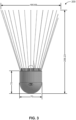
- FIG. 3 is a front view illustration of the anemometer (200) of Figure 2 with exemplary dimensions, constructed and operative in accordance with an embodiment of the present invention.
- Anemometer 200 is depicted in an upright position, with an overall height (including both portion 210 and portion 220) of approximately 256.23 mm.
- the height and width (and diameter) of first portion 210 is approximately 70 mm, and the width of the distal end (conical edge) of second portion 220 is approximately 185.69 mm. It is appreciated that these represent exemplary dimensions only, and alternative dimensions may also be suitable.
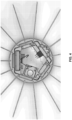
- First portion 210 includes a speaker 232, a microphone 234, a camera 236, a transceiver 238, an altimeter 240, a clock 241, a compass 242, an accelerometer 244, a g-force meter 246, an inclinometer 248, a radar altimeter 250, a global positing system (GPS) 256, a processor 252, and a power source 254. At least some of the above components may be optional.
- GPS global positing system
Landscapes
- Physics & Mathematics (AREA)
- General Physics & Mathematics (AREA)
- Engineering & Computer Science (AREA)
- Aviation & Aerospace Engineering (AREA)
- Environmental & Geological Engineering (AREA)
- Remote Sensing (AREA)
- Radar, Positioning & Navigation (AREA)
- Life Sciences & Earth Sciences (AREA)
- Atmospheric Sciences (AREA)
- Biodiversity & Conservation Biology (AREA)
- Ecology (AREA)
- Environmental Sciences (AREA)
- Indicating Or Recording The Presence, Absence, Or Direction Of Movement (AREA)
Claims (14)
- Anemometer (100, 200) zum unabhängigen Messen von Windgeschwindigkeit und Windrichtung in einem Fluidmedium, wobei das Anemometer (100, 200) dazu konfiguriert ist, eingesetzt zu werden, um autonom entlang einer Trajektorie des Fluidmediums zu fallen, und Folgendes umfasst:einen ersten Anemometerabschnitt (110, 210); undeinen zweiten Anemometerabschnitt (120, 220), der mit einem verschiedenen Luftwiderstandskoeffizienten als der erste Anemometerabschnitt (110, 210) konfiguriert ist, was zu einem verschiedenen Windwiderstand in dem Fluidmedium als der erste Anemometerabschnitt (110, 210) führt,wobei der verschiedene Luftwiderstandskoeffizient und der verschiedene Windwiderstand des zweiten Anemometerabschnitts (120, 220) eine Neigung des Anemometers in Richtung der Windrichtung bewirkt, undwobei der Luftwiderstandskoeffizient des Anemometers (100, 200) bewirkt, dass eine anfängliche ballistische Trajektorie so gekürzt wird, dass das Anemometer (100, 200) fast unmittelbar nach dem Einsetzen in einen Freifallabstieg eintritt;wobei das Anemometer (100, 200) ferner Folgendes umfasst:mindestens einen Neigungsmesser (248), der mit mindestens einem Anemometerabschnitt gekoppelt ist, wobei der Neigungsmesser (248) dazu konfiguriert ist, Neigungsmessungen des Anemometers (100, 200) ab dem Zeitpunkt zu erhalten, an dem das Anemometer (100, 200) den Freifallabstieg beginnt; undmindestens einen Speicher/Sender, der mit mindestens einem Anemometerabschnitt gekoppelt und dazu konfiguriert ist, die Neigungsmessungen zu speichern oder zu senden,wobei das Anemometer dazu konfiguriert ist, die lokale Windrichtung entlang der Trajektorie aus den Neigungsmessungen basierend auf der Richtung der Neigung des Anemometers (100, 200) in Korrelation mit den Messzeitpunkten zu bestimmen und die lokale Windgeschwindigkeit entlang der Trajektorie aus den Neigungsmessungen basierend auf der Richtung der Neigung des Anemometers (100, 200) in Korrelation mit den Messzeitpunkten zu bestimmen.
- Anemometer nach Anspruch 1, wobei das Anemometer dazu konfiguriert ist, von einer sich bewegenden Flugplattform eingesetzt zu werden.
- Anemometer nach Anspruch 1, wobei sich der zweite Anemometerabschnitt (120, 220) von dem ersten Anemometerabschnitt (110, 210) in einem weiteren Attribut unterscheidet, das aus der Gruppe ausgewählt ist, die aus Folgendem besteht: Masse; Form; Dichte; spezifisches Gewicht; Bewegungsfreiheit; und einer beliebigen Kombination des Vorstehenden.
- Anemometer nach Anspruch 1, umfassend einen kugelförmigen ersten Abschnitt (210) und einen konischen zweiten Abschnitt (220), der in den kugelförmigen ersten Abschnitt (210) eingebettet ist, wobei der konische zweite Abschnitt (220) eine kleinere Masse und eine größere Oberfläche als der kugelförmige erste Abschnitt (210) aufweist.
- Anemometer nach Anspruch 1, wobei der zweite Anemometerabschnitt einen zylindrischen Stab (120) umfasst, der sich von einer flachen Oberfläche des ersten Anemometerabschnitts (110) erstreckt und eine halbkugelförmige Form und eine schwerere Masse als der erste Anemometerabschnitt aufweist.
- Anemometer nach Anspruch 1, wobei der zweite Anemometerabschnitt (120, 220) ein Material mit hoher Elastizität oder hoher Flexibilität umfasst und der erste Anemometerabschnitt (110, 210) ein Material mit hoher Steifigkeit oder hoher Steifigkeit umfasst.
- Anemometer nach Anspruch 1, wobei das Fluidmedium aus der Gruppe ausgewählt ist, die aus Folgendem besteht: Luft; und Wasser.
- Anemometer nach Anspruch 1, ferner umfassend mindestens ein Element, das aus der Liste ausgewählt ist, die aus Folgendem besteht: einem Kompass (242), der dazu konfiguriert ist, Richtungsmessungen des Anemometers zu erhalten; einem Höhenmesser (240, 250), der dazu konfiguriert ist, Höhenmessungen des Anemometers zu erhalten; einem Beschleunigungsmesser (244), der dazu konfiguriert ist, Beschleunigungsmessungen des Anemometers zu erhalten; einem g-Kraftmesser (246), der dazu konfiguriert ist, g-Kraftmessungen des Anemometers zu erhalten; einem globalen Positionierungssystem (256), das dazu konfiguriert ist, Geolokalisierungsmessungen des Anemometers zu erhalten; einem Sendeempfänger (238), der dazu konfiguriert ist, Daten zu senden oder zu empfangen; einem Lautsprecher (232), der dazu konfiguriert ist, Audioausgabe zu erzeugen; einem Mikrofon (234), das dazu konfiguriert ist, Audioeingabe zu empfangen; einer Uhr (241), die dazu konfiguriert ist, Zeitstempel zu erstellen; einer Kamera (236), die dazu konfiguriert ist, mindestens ein Bild aufzunehmen; und einem Prozessor (252), der dazu konfiguriert ist, die Messungen zu empfangen und die lokale Windrichtung und die lokale Windgeschwindigkeit basierend auf den empfangenen Messungen zu bestimmen.
- Anemometer nach Anspruch 8, wobei der Prozessor (252) dazu konfiguriert ist, die lokale Windgeschwindigkeit und die lokale Windrichtung durch Vergleichen des Verhaltens des Anemometers unter Nichtwindbedingungen mit dem Verhalten des Anemometers unter Windbedingungen zu bestimmen.
- Anemometer nach Anspruch 8, wobei der Prozessor (252) dazu konfiguriert ist, die lokale Windgeschwindigkeit und die lokale Windrichtung einer vertikalen Windkomponente durch Vergleichen der Sinkgeschwindigkeit des Anemometers unter Nichtwindbedingungen mit der Sinkgeschwindigkeit des Anemometers unter Windbedingungen zu bestimmen.
- Verfahren zum unabhängigen Messen von Windgeschwindigkeit und Windrichtung in einem Fluidmedium mit einem Anemometer (100, 200) nach einem der vorhergehenden Ansprüche, wobei das Verfahren die folgenden Vorgänge umfasst:Einsetzen eines Anemometers (100, 200), um autonom entlang einer Trajektorie des Fluidmediums zu fallen, wobei das Anemometer (100, 200) Folgendes umfasst: einen ersten Anemometerabschnitt (110, 210) und einen zweiten Anemometerabschnitt (120, 220), die mit einem anderen Luftwiderstandskoeffizienten als der erste Anemometerabschnitt (110, 210) konfiguriert sind, was zu einem anderen Windwiderstand in dem Fluidmedium als der erste Anemometerabschnitt (110, 210) führt,wobei der verschiedene Luftwiderstandskoeffizient und der verschiedene Windwiderstand des zweiten Anemometerabschnitts (120, 220) eine Neigung des Anemometers in Richtung der Windrichtung bewirkt, und wobei der Luftwiderstandskoeffizient des Anemometers (100, 200) bewirkt, dass eine anfängliche ballistische Trajektorie so gekürzt wird, dass das Anemometer (100, 200) fast unmittelbar nach dem Einsetzen in einen Freifallabstieg eintritt;Erfassen von Neigungsmessungen des Anemometers ab dem Zeitpunkt, an dem das Anemometer (200) den Freifallabstieg beginnt, unter Verwendung mindestens eines Neigungsmessers (248), der mit mindestens einem Anemometerabschnitt gekoppelt ist;Speichern oder Senden der Neigungsmessungen unter Verwendung mindestens einer Einheit, die mit mindestens einem Anemometerabschnitt gekoppelt ist; undBestimmen der lokalen Windrichtung entlang der Trajektorie aus den Neigungsmessungen basierend auf der Richtung der Neigung des Anemometers in Korrelation mit den Messzeitpunkten, undBestimmen der lokalen Windgeschwindigkeit entlang der Trajektorie aus den Neigungsmessungen basierend auf dem Grad der Neigung des Anemometers in Korrelation mit den Messzeitpunkten.
- Verfahren nach Anspruch 11, wobei das Anemometer (200) von einer sich bewegenden Flugplattform eingesetzt wird.
- Verfahren nach Anspruch 11, wobei das Bestimmen der lokalen Windgeschwindigkeit und der lokalen Windrichtung das Vergleichen des Verhaltens des Anemometers unter Nichtwindbedingungen mit dem Verhalten des Anemometers unter Windbedingungen umfasst.
- Verfahren nach Anspruch 11, wobei das Bestimmen der lokalen Windgeschwindigkeit und der lokalen Windrichtung das Bestimmen der lokalen Windgeschwindigkeit und der lokalen Windrichtung einer vertikalen Windkomponente durch Vergleichen der Sinkgeschwindigkeit des Anemometers unter Nichtwindbedingungen mit der Sinkgeschwindigkeit des Anemometers unter Windbedingungen umfasst.
Applications Claiming Priority (2)
| Application Number | Priority Date | Filing Date | Title |
|---|---|---|---|
| IL260035A IL260035B (en) | 2018-06-14 | 2018-06-14 | anemometer |
| PCT/IL2019/050575 WO2019239398A1 (en) | 2018-06-14 | 2019-05-22 | Anemometer |
Publications (3)
| Publication Number | Publication Date |
|---|---|
| EP3807653A1 EP3807653A1 (de) | 2021-04-21 |
| EP3807653A4 EP3807653A4 (de) | 2022-03-09 |
| EP3807653B1 true EP3807653B1 (de) | 2025-04-02 |
Family
ID=63014219
Family Applications (1)
| Application Number | Title | Priority Date | Filing Date |
|---|---|---|---|
| EP19819615.6A Active EP3807653B1 (de) | 2018-06-14 | 2019-05-22 | Anemometer |
Country Status (6)
| Country | Link |
|---|---|
| US (1) | US11300583B2 (de) |
| EP (1) | EP3807653B1 (de) |
| AU (1) | AU2019286651B2 (de) |
| CA (1) | CA3097491C (de) |
| IL (1) | IL260035B (de) |
| WO (1) | WO2019239398A1 (de) |
Families Citing this family (1)
| Publication number | Priority date | Publication date | Assignee | Title |
|---|---|---|---|---|
| USD972723S1 (en) * | 2021-03-17 | 2022-12-13 | Angiodynamics, Inc. | Reinforcement arms and collar for an expandable cannula tip |
Citations (3)
| Publication number | Priority date | Publication date | Assignee | Title |
|---|---|---|---|---|
| US20140203184A1 (en) * | 2011-09-23 | 2014-07-24 | Visualant, Inc. | Fluid medium sensor system and method |
| US20150027220A1 (en) * | 2012-02-07 | 2015-01-29 | Ventus-Product Development & Consulting Ltd. | Wind parameter indication |
| WO2017153987A1 (en) * | 2016-03-09 | 2017-09-14 | First Airborne Limited | Device and method for accurate wind measurement |
Family Cites Families (8)
| Publication number | Priority date | Publication date | Assignee | Title |
|---|---|---|---|---|
| US3260940A (en) * | 1951-07-03 | 1966-07-12 | Delbert A Deisinger | Radiosonde for weather telemetering |
| US5173690A (en) * | 1990-02-23 | 1992-12-22 | Viz Manufacturing Company | Passive ranging system utilizing range tone signals |
| US6421010B1 (en) * | 2001-02-16 | 2002-07-16 | The United States Of America As Represented By The Secretary Of Commerce | Atmospheric sondes and method for tracking |
| DE10249590A1 (de) * | 2002-10-24 | 2004-05-13 | Diehl Munitionssysteme Gmbh & Co. Kg | Verfahren zur Bestimmung des Höhenprofiles der horizontalen Windgeschwindigkeit |
| CN2894753Y (zh) * | 2006-02-07 | 2007-05-02 | 阴贵生 | 羽毛球毽子语音累计报数器装置 |
| US20140224009A1 (en) * | 2013-02-13 | 2014-08-14 | Hdt Expeditionary Systems | High velocity wind sonde |
| US11130042B2 (en) * | 2016-02-02 | 2021-09-28 | Bao Tran | Smart device |
| CN206167823U (zh) * | 2016-10-20 | 2017-05-17 | 上海雍敏信息科技有限公司 | 智能羽毛球装置及智能羽毛球速度测量系统 |
-
2018
- 2018-06-14 IL IL260035A patent/IL260035B/en active IP Right Grant
-
2019
- 2019-05-22 AU AU2019286651A patent/AU2019286651B2/en active Active
- 2019-05-22 WO PCT/IL2019/050575 patent/WO2019239398A1/en not_active Ceased
- 2019-05-22 EP EP19819615.6A patent/EP3807653B1/de active Active
- 2019-05-22 US US15/733,801 patent/US11300583B2/en active Active
- 2019-05-22 CA CA3097491A patent/CA3097491C/en active Active
Patent Citations (3)
| Publication number | Priority date | Publication date | Assignee | Title |
|---|---|---|---|---|
| US20140203184A1 (en) * | 2011-09-23 | 2014-07-24 | Visualant, Inc. | Fluid medium sensor system and method |
| US20150027220A1 (en) * | 2012-02-07 | 2015-01-29 | Ventus-Product Development & Consulting Ltd. | Wind parameter indication |
| WO2017153987A1 (en) * | 2016-03-09 | 2017-09-14 | First Airborne Limited | Device and method for accurate wind measurement |
Also Published As
| Publication number | Publication date |
|---|---|
| CA3097491C (en) | 2021-03-02 |
| US20210231700A1 (en) | 2021-07-29 |
| CA3097491A1 (en) | 2019-12-19 |
| IL260035B (en) | 2019-07-31 |
| IL260035A (en) | 2018-07-31 |
| EP3807653A1 (de) | 2021-04-21 |
| AU2019286651A1 (en) | 2020-10-15 |
| EP3807653A4 (de) | 2022-03-09 |
| AU2019286651B2 (en) | 2020-12-10 |
| WO2019239398A1 (en) | 2019-12-19 |
| US11300583B2 (en) | 2022-04-12 |
Similar Documents
| Publication | Publication Date | Title |
|---|---|---|
| US9103946B2 (en) | Wind parameter indication | |
| Elston et al. | Overview of small fixed-wing unmanned aircraft for meteorological sampling | |
| Martin et al. | Meteorological profiling of the lower troposphere using the research UAV" M 2 AV Carolo" | |
| Haering Jr | Airdata measurement and calibration | |
| Gracey | Summary of methods of measuring angle of attack on aircraft | |
| US20100014066A1 (en) | Winds aloft profiling system | |
| WO2020261255A1 (en) | Geolocation of head-mounted image sensor using celestial navigation | |
| US7761197B2 (en) | Method and device for detecting air turbulence in the environment of an aircraft | |
| EP3807653B1 (de) | Anemometer | |
| Rowland et al. | Fine-scale measurements of microwave refractivity profiles with helicopter and low-cost rocket probes | |
| De Bruijn et al. | Measuring low-altitude winds with a hot-air balloon and their validation with Cabauw tower observations | |
| Marlton | On the development, characterisation and applications of a balloon-borne atmospheric turbulence sensor | |
| Makshakov et al. | Determination method of the aircrafts flying height using absolute pressure sensors | |
| Foster et al. | Meteorological Data Collection for Three-Dimensional Forecasting Advancements | |
| Cheng et al. | Test Flight of a Stratospheric Sonic Anemometer Prototype | |
| Gonzalo et al. | Lighter-than-air particle velocimetry for wind speed profile measurement | |
| Zhu et al. | Stratospheric Turbulence Measurements with Payload FiSH and Meteorological Balloons | |
| Avery et al. | Sensor Suite Development for a Weather UAV | |
| Addasi | Development of an Quadcopter Unmanned Aerial Vehicle for Atmospheric Remote Sensing | |
| Lawford et al. | AGARD Flight Test Techniques Series. Volume 1. Calibration of Air-Data Systems and Flow Direction Sensors | |
| Spieß et al. | Comparison of ‘M2AV’unmanned airborne meteorological measurements with remote sensing and the Helipod | |
| Yeung et al. | Measuring atmospheric gusts at low altitude | |
| Teskey et al. | Determining a free flight performance surface by mathematical optimization techniques utilizing an air speed indicator, MEMS inertial sensors and a variomete. | |
| Nelson | A Revised Technique for Measuring Vertical Velocity Using Dropsondes | |
| Casassa et al. | A low-cost UAS for monitoring vertical wind distribution |
Legal Events
| Date | Code | Title | Description |
|---|---|---|---|
| STAA | Information on the status of an ep patent application or granted ep patent |
Free format text: STATUS: THE INTERNATIONAL PUBLICATION HAS BEEN MADE |
|
| PUAI | Public reference made under article 153(3) epc to a published international application that has entered the european phase |
Free format text: ORIGINAL CODE: 0009012 |
|
| STAA | Information on the status of an ep patent application or granted ep patent |
Free format text: STATUS: REQUEST FOR EXAMINATION WAS MADE |
|
| 17P | Request for examination filed |
Effective date: 20210107 |
|
| AK | Designated contracting states |
Kind code of ref document: A1 Designated state(s): AL AT BE BG CH CY CZ DE DK EE ES FI FR GB GR HR HU IE IS IT LI LT LU LV MC MK MT NL NO PL PT RO RS SE SI SK SM TR |
|
| AX | Request for extension of the european patent |
Extension state: BA ME |
|
| DAV | Request for validation of the european patent (deleted) | ||
| DAX | Request for extension of the european patent (deleted) | ||
| A4 | Supplementary search report drawn up and despatched |
Effective date: 20220208 |
|
| RIC1 | Information provided on ipc code assigned before grant |
Ipc: G01W 1/08 20060101ALI20220202BHEP Ipc: G01P 13/02 20060101ALI20220202BHEP Ipc: G01P 5/02 20060101AFI20220202BHEP |
|
| STAA | Information on the status of an ep patent application or granted ep patent |
Free format text: STATUS: EXAMINATION IS IN PROGRESS |
|
| 17Q | First examination report despatched |
Effective date: 20230403 |
|
| GRAP | Despatch of communication of intention to grant a patent |
Free format text: ORIGINAL CODE: EPIDOSNIGR1 |
|
| STAA | Information on the status of an ep patent application or granted ep patent |
Free format text: STATUS: GRANT OF PATENT IS INTENDED |
|
| INTG | Intention to grant announced |
Effective date: 20240920 |
|
| GRAS | Grant fee paid |
Free format text: ORIGINAL CODE: EPIDOSNIGR3 |
|
| GRAA | (expected) grant |
Free format text: ORIGINAL CODE: 0009210 |
|
| STAA | Information on the status of an ep patent application or granted ep patent |
Free format text: STATUS: THE PATENT HAS BEEN GRANTED |
|
| AK | Designated contracting states |
Kind code of ref document: B1 Designated state(s): AL AT BE BG CH CY CZ DE DK EE ES FI FR GB GR HR HU IE IS IT LI LT LU LV MC MK MT NL NO PL PT RO RS SE SI SK SM TR |
|
| REG | Reference to a national code |
Ref country code: GB Ref legal event code: FG4D |
|
| REG | Reference to a national code |
Ref country code: CH Ref legal event code: EP |
|
| REG | Reference to a national code |
Ref country code: IE Ref legal event code: FG4D |
|
| REG | Reference to a national code |
Ref country code: DE Ref legal event code: R096 Ref document number: 602019068175 Country of ref document: DE |
|
| P01 | Opt-out of the competence of the unified patent court (upc) registered |
Free format text: CASE NUMBER: APP_17732/2025 Effective date: 20250411 |
|
| PGFP | Annual fee paid to national office [announced via postgrant information from national office to epo] |
Ref country code: DE Payment date: 20250530 Year of fee payment: 7 |
|
| PGFP | Annual fee paid to national office [announced via postgrant information from national office to epo] |
Ref country code: GB Payment date: 20250530 Year of fee payment: 7 |
|
| PGFP | Annual fee paid to national office [announced via postgrant information from national office to epo] |
Ref country code: FR Payment date: 20250530 Year of fee payment: 7 |
|
| REG | Reference to a national code |
Ref country code: NL Ref legal event code: MP Effective date: 20250402 |
|
| PG25 | Lapsed in a contracting state [announced via postgrant information from national office to epo] |
Ref country code: NL Free format text: LAPSE BECAUSE OF FAILURE TO SUBMIT A TRANSLATION OF THE DESCRIPTION OR TO PAY THE FEE WITHIN THE PRESCRIBED TIME-LIMIT Effective date: 20250402 |
|
| REG | Reference to a national code |
Ref country code: AT Ref legal event code: MK05 Ref document number: 1781744 Country of ref document: AT Kind code of ref document: T Effective date: 20250402 |
|
| PG25 | Lapsed in a contracting state [announced via postgrant information from national office to epo] |
Ref country code: PT Free format text: LAPSE BECAUSE OF FAILURE TO SUBMIT A TRANSLATION OF THE DESCRIPTION OR TO PAY THE FEE WITHIN THE PRESCRIBED TIME-LIMIT Effective date: 20250804 Ref country code: FI Free format text: LAPSE BECAUSE OF FAILURE TO SUBMIT A TRANSLATION OF THE DESCRIPTION OR TO PAY THE FEE WITHIN THE PRESCRIBED TIME-LIMIT Effective date: 20250402 Ref country code: ES Free format text: LAPSE BECAUSE OF FAILURE TO SUBMIT A TRANSLATION OF THE DESCRIPTION OR TO PAY THE FEE WITHIN THE PRESCRIBED TIME-LIMIT Effective date: 20250402 |
|
| REG | Reference to a national code |
Ref country code: LT Ref legal event code: MG9D |
|
| PG25 | Lapsed in a contracting state [announced via postgrant information from national office to epo] |
Ref country code: NO Free format text: LAPSE BECAUSE OF FAILURE TO SUBMIT A TRANSLATION OF THE DESCRIPTION OR TO PAY THE FEE WITHIN THE PRESCRIBED TIME-LIMIT Effective date: 20250702 Ref country code: GR Free format text: LAPSE BECAUSE OF FAILURE TO SUBMIT A TRANSLATION OF THE DESCRIPTION OR TO PAY THE FEE WITHIN THE PRESCRIBED TIME-LIMIT Effective date: 20250703 |
|
| PG25 | Lapsed in a contracting state [announced via postgrant information from national office to epo] |
Ref country code: PL Free format text: LAPSE BECAUSE OF FAILURE TO SUBMIT A TRANSLATION OF THE DESCRIPTION OR TO PAY THE FEE WITHIN THE PRESCRIBED TIME-LIMIT Effective date: 20250402 |
|
| PG25 | Lapsed in a contracting state [announced via postgrant information from national office to epo] |
Ref country code: BG Free format text: LAPSE BECAUSE OF FAILURE TO SUBMIT A TRANSLATION OF THE DESCRIPTION OR TO PAY THE FEE WITHIN THE PRESCRIBED TIME-LIMIT Effective date: 20250402 |
|
| PG25 | Lapsed in a contracting state [announced via postgrant information from national office to epo] |
Ref country code: HR Free format text: LAPSE BECAUSE OF FAILURE TO SUBMIT A TRANSLATION OF THE DESCRIPTION OR TO PAY THE FEE WITHIN THE PRESCRIBED TIME-LIMIT Effective date: 20250402 |
|
| PG25 | Lapsed in a contracting state [announced via postgrant information from national office to epo] |
Ref country code: AT Free format text: LAPSE BECAUSE OF FAILURE TO SUBMIT A TRANSLATION OF THE DESCRIPTION OR TO PAY THE FEE WITHIN THE PRESCRIBED TIME-LIMIT Effective date: 20250402 |
|
| PG25 | Lapsed in a contracting state [announced via postgrant information from national office to epo] |
Ref country code: RS Free format text: LAPSE BECAUSE OF FAILURE TO SUBMIT A TRANSLATION OF THE DESCRIPTION OR TO PAY THE FEE WITHIN THE PRESCRIBED TIME-LIMIT Effective date: 20250702 |
|
| PG25 | Lapsed in a contracting state [announced via postgrant information from national office to epo] |
Ref country code: IS Free format text: LAPSE BECAUSE OF FAILURE TO SUBMIT A TRANSLATION OF THE DESCRIPTION OR TO PAY THE FEE WITHIN THE PRESCRIBED TIME-LIMIT Effective date: 20250802 |
|
| PG25 | Lapsed in a contracting state [announced via postgrant information from national office to epo] |
Ref country code: LV Free format text: LAPSE BECAUSE OF FAILURE TO SUBMIT A TRANSLATION OF THE DESCRIPTION OR TO PAY THE FEE WITHIN THE PRESCRIBED TIME-LIMIT Effective date: 20250402 |
|
| REG | Reference to a national code |
Ref country code: CH Ref legal event code: H13 Free format text: ST27 STATUS EVENT CODE: U-0-0-H10-H13 (AS PROVIDED BY THE NATIONAL OFFICE) Effective date: 20251223 |
|
| REG | Reference to a national code |
Ref country code: DE Ref legal event code: R097 Ref document number: 602019068175 Country of ref document: DE |
|
| PG25 | Lapsed in a contracting state [announced via postgrant information from national office to epo] |
Ref country code: DK Free format text: LAPSE BECAUSE OF FAILURE TO SUBMIT A TRANSLATION OF THE DESCRIPTION OR TO PAY THE FEE WITHIN THE PRESCRIBED TIME-LIMIT Effective date: 20250402 Ref country code: SM Free format text: LAPSE BECAUSE OF FAILURE TO SUBMIT A TRANSLATION OF THE DESCRIPTION OR TO PAY THE FEE WITHIN THE PRESCRIBED TIME-LIMIT Effective date: 20250402 |
|
| PG25 | Lapsed in a contracting state [announced via postgrant information from national office to epo] |
Ref country code: LU Free format text: LAPSE BECAUSE OF NON-PAYMENT OF DUE FEES Effective date: 20250522 |
|
| PG25 | Lapsed in a contracting state [announced via postgrant information from national office to epo] |
Ref country code: CH Free format text: LAPSE BECAUSE OF NON-PAYMENT OF DUE FEES Effective date: 20250531 |
|
| PG25 | Lapsed in a contracting state [announced via postgrant information from national office to epo] |
Ref country code: CZ Free format text: LAPSE BECAUSE OF FAILURE TO SUBMIT A TRANSLATION OF THE DESCRIPTION OR TO PAY THE FEE WITHIN THE PRESCRIBED TIME-LIMIT Effective date: 20250402 |
|
| PG25 | Lapsed in a contracting state [announced via postgrant information from national office to epo] |
Ref country code: EE Free format text: LAPSE BECAUSE OF FAILURE TO SUBMIT A TRANSLATION OF THE DESCRIPTION OR TO PAY THE FEE WITHIN THE PRESCRIBED TIME-LIMIT Effective date: 20250402 |
|
| PG25 | Lapsed in a contracting state [announced via postgrant information from national office to epo] |
Ref country code: RO Free format text: LAPSE BECAUSE OF FAILURE TO SUBMIT A TRANSLATION OF THE DESCRIPTION OR TO PAY THE FEE WITHIN THE PRESCRIBED TIME-LIMIT Effective date: 20250402 Ref country code: SK Free format text: LAPSE BECAUSE OF FAILURE TO SUBMIT A TRANSLATION OF THE DESCRIPTION OR TO PAY THE FEE WITHIN THE PRESCRIBED TIME-LIMIT Effective date: 20250402 |
|
| PG25 | Lapsed in a contracting state [announced via postgrant information from national office to epo] |
Ref country code: IT Free format text: LAPSE BECAUSE OF FAILURE TO SUBMIT A TRANSLATION OF THE DESCRIPTION OR TO PAY THE FEE WITHIN THE PRESCRIBED TIME-LIMIT Effective date: 20250402 |
|
| REG | Reference to a national code |
Ref country code: BE Ref legal event code: MM Effective date: 20250531 |
|
| PG25 | Lapsed in a contracting state [announced via postgrant information from national office to epo] |
Ref country code: MC Free format text: LAPSE BECAUSE OF FAILURE TO SUBMIT A TRANSLATION OF THE DESCRIPTION OR TO PAY THE FEE WITHIN THE PRESCRIBED TIME-LIMIT Effective date: 20250402 |
|
| PLBE | No opposition filed within time limit |
Free format text: ORIGINAL CODE: 0009261 |
|
| STAA | Information on the status of an ep patent application or granted ep patent |
Free format text: STATUS: NO OPPOSITION FILED WITHIN TIME LIMIT |
|
| REG | Reference to a national code |
Ref country code: CH Ref legal event code: L10 Free format text: ST27 STATUS EVENT CODE: U-0-0-L10-L00 (AS PROVIDED BY THE NATIONAL OFFICE) Effective date: 20260211 |
|
| 26N | No opposition filed |
Effective date: 20260105 |
|
| PG25 | Lapsed in a contracting state [announced via postgrant information from national office to epo] |
Ref country code: IE Free format text: LAPSE BECAUSE OF NON-PAYMENT OF DUE FEES Effective date: 20250522 |
|
| PG25 | Lapsed in a contracting state [announced via postgrant information from national office to epo] |
Ref country code: BE Free format text: LAPSE BECAUSE OF NON-PAYMENT OF DUE FEES Effective date: 20250531 |