EP3807602B1 - Gas meter - Google Patents
Gas meter Download PDFInfo
- Publication number
- EP3807602B1 EP3807602B1 EP19742486.4A EP19742486A EP3807602B1 EP 3807602 B1 EP3807602 B1 EP 3807602B1 EP 19742486 A EP19742486 A EP 19742486A EP 3807602 B1 EP3807602 B1 EP 3807602B1
- Authority
- EP
- European Patent Office
- Prior art keywords
- metering device
- outlet
- box
- shaped body
- gas meter
- Prior art date
- Legal status (The legal status is an assumption and is not a legal conclusion. Google has not performed a legal analysis and makes no representation as to the accuracy of the status listed.)
- Active
Links
Images



Classifications
-
- G—PHYSICS
- G01—MEASURING; TESTING
- G01F—MEASURING VOLUME, VOLUME FLOW, MASS FLOW OR LIQUID LEVEL; METERING BY VOLUME
- G01F15/00—Details of, or accessories for, apparatus of groups G01F1/00 - G01F13/00 insofar as such details or appliances are not adapted to particular types of such apparatus
- G01F15/14—Casings, e.g. of special material
-
- G—PHYSICS
- G01—MEASURING; TESTING
- G01F—MEASURING VOLUME, VOLUME FLOW, MASS FLOW OR LIQUID LEVEL; METERING BY VOLUME
- G01F15/00—Details of, or accessories for, apparatus of groups G01F1/00 - G01F13/00 insofar as such details or appliances are not adapted to particular types of such apparatus
- G01F15/18—Supports or connecting means for meters
-
- G—PHYSICS
- G01—MEASURING; TESTING
- G01F—MEASURING VOLUME, VOLUME FLOW, MASS FLOW OR LIQUID LEVEL; METERING BY VOLUME
- G01F15/00—Details of, or accessories for, apparatus of groups G01F1/00 - G01F13/00 insofar as such details or appliances are not adapted to particular types of such apparatus
- G01F15/18—Supports or connecting means for meters
- G01F15/185—Connecting means, e.g. bypass conduits
-
- G—PHYSICS
- G01—MEASURING; TESTING
- G01F—MEASURING VOLUME, VOLUME FLOW, MASS FLOW OR LIQUID LEVEL; METERING BY VOLUME
- G01F15/00—Details of, or accessories for, apparatus of groups G01F1/00 - G01F13/00 insofar as such details or appliances are not adapted to particular types of such apparatus
- G01F15/005—Valves
-
- G—PHYSICS
- G01—MEASURING; TESTING
- G01F—MEASURING VOLUME, VOLUME FLOW, MASS FLOW OR LIQUID LEVEL; METERING BY VOLUME
- G01F15/00—Details of, or accessories for, apparatus of groups G01F1/00 - G01F13/00 insofar as such details or appliances are not adapted to particular types of such apparatus
- G01F15/007—Details of, or accessories for, apparatus of groups G01F1/00 - G01F13/00 insofar as such details or appliances are not adapted to particular types of such apparatus comprising means to prevent fraud
-
- G—PHYSICS
- G01—MEASURING; TESTING
- G01F—MEASURING VOLUME, VOLUME FLOW, MASS FLOW OR LIQUID LEVEL; METERING BY VOLUME
- G01F15/00—Details of, or accessories for, apparatus of groups G01F1/00 - G01F13/00 insofar as such details or appliances are not adapted to particular types of such apparatus
- G01F15/12—Cleaning arrangements; Filters
-
- G—PHYSICS
- G01—MEASURING; TESTING
- G01F—MEASURING VOLUME, VOLUME FLOW, MASS FLOW OR LIQUID LEVEL; METERING BY VOLUME
- G01F15/00—Details of, or accessories for, apparatus of groups G01F1/00 - G01F13/00 insofar as such details or appliances are not adapted to particular types of such apparatus
- G01F15/12—Cleaning arrangements; Filters
- G01F15/125—Filters
Definitions
- the invention concerns a gas meter.
- Gas meters of the static type meaning gas meters that do not have moving members, are currently known and widespread; these gas meters incorporate a sensor that measures a value and transmits the measured data to an electronic control unit located outside the metering unit.
- Meters which, in order to overcome this drawback, are configured in such a way as to stop a gas flow in case of anomalies or in case of tampering attempts or in case of failure to pay the gas bill by the user.
- gas meters which comprise a box-shaped body provided with an inlet mouth and an outlet mouth, both facing upwards with respect to a normal configuration of use of the gas meter; inside the box-shaped body there are, in the given order, a mechanical filter, at the level of the inlet mouth, a solenoid valve designed to intercept the flow and a metering device suited to measure one or more parameters for the determination of the gas flow rate such as, for example, a device of the static type provided with temperature sensors.
- the position of the metering device is such that the same metering device is directly connected to the outlet connection element and arranged so that it is adjacent to the latter, a position in which the metering device is likely to be tampered with since, as explained above, the current regulations do not require the outlet connection element to be sealed.
- a mechanical filter may be positioned before the valve, for example a filter of the type with metal mesh, configured to hold back the larger sized particles but, in any case, finer dust falls inside the solenoid valve by gravity, thus negatively affecting its operation over time.
- the particles are not collected in a circumscribed space and are continuously hit by the main gas flow before this gets into the solenoid valve which, therefore, ends up with collecting most of such particles.
- a gas meter according to the invention is indicated as a whole by the numeral 10.
- Said gas meter 10 comprises
- a metering device 19 designed to measure one or more parameters for the determination of the gas flow rate; this metering device 19, too, is provided with an inlet opening 19a and an outlet opening 19b of its own.
- the specific characteristic of the gas meter 10 according to the invention lies in that it comprises:
- the metering device 19 is positioned in an intermediate area between the inlet duct 25 and the outlet duct 40.
- the term 'intermediate area' is used to indicate the space included between the inlet duct 25 and the outlet duct 40 inside the box-shaped body 11.
- the metering device 19 must therefore be intended as suited to be positioned in any point and with any configuration in said space included between the inlet duct 25 and the outlet duct 40.
- said means 20, configured in such a way as to deviate the gas flowing out through the outlet opening 19b of the metering device 19 towards the inlet opening 40a of the outlet duct 40, define a trajectory X3 comprising a deviation that develops over a deviation angle 21 between a direction X1 crossing the metering device 19 and a direction X2 crossing the outlet duct 40, said deviation angle 21 being included in an interval ranging between a neighbourhood of 90° and 225°.
- the expression 'neighbourhood of 90°' is used to indicate an interval between -15° and +15° with respect to 90°.
- Said deviation angle 21 is preferably included between 91° and 225°.
- said deviation angle 21 is equal to 180°, as clearly visible in Figures 3 and 4 .
- the box-shaped body 11 comprises, with respect to a normal configuration of use, a top side 12, an opposite bottom side 13 and a side wall 14.
- the outlet mouth 16 is defined on the top side 12.
- the inlet mouth 15 and the outlet mouth 16 are defined on the top side 12.
- inlet mouth 15 and the outlet mouth 16 can both be provided, in an example not being part of the present invention, on another, yet the same, side different from the top side 12.
- inlet mouth 15 and the outlet mouth 16 can each be provided, in an example not being part of the present invention, on a respective side of the box-shaped body 11, different from the side on which the other mouth is provided.
- the gas meter 10 comprises also an on-off valve 18 suited to intercept the gas flow across the gas meter 10, said on-off valve 18 being provided with an inlet opening 18a and an outlet opening 18b.
- the on-off valve 18 is located at the level of the outlet mouth 16 of the box-shaped body 11.
- the on-off valve 18 is a part of the outlet duct 40.
- the gas meter 10 comprises a first threaded connection element 23 at the level of the inlet mouth 15 of the box-shaped body 11 and a second threaded connection element 24 at the level of the outlet mouth 16 of the box-shaped body 11.
- the gas meter 10 comprises also filtering means 17 suited to filter the gas flow.
- Said filtering means 17 comprise a dust deposit chamber 26 defined between the bottom side 13 of the box-shaped body 11 and a mechanical filtering partition 27 interposed between the bottom side 13 and the top side 12.
- Said mechanical filtering partition 27 comprises a mesh portion 28.
- Said mesh portion 28 has through openings 28a; the dimensions of said through openings 28a are such as to prevent the passage of dust particles with particularly large diameter, meaning that said through openings 28a have a cross section whose main dimension, for example their side if they are square in shape or their diameter if they are round in shape, is included between 0.5 and 3 mm, and preferably is equal to 1 mm.
- the mesh portion 28 may comprise several filtering layers, sandwich-layered or spaced from one another, each layer being constituted by a mesh or a net or a non-woven fabric.
- the inlet duct 25 extends from the inlet mouth 15 of the box-shaped body 11 to the inside of the dust deposit chamber 26.
- Said inlet duct 25 is configured in such a way that the gas flow entering through the first threaded connection element 23 is not dispersed in the inner compartment of the box-shaped body 11 but is directly and completely conveyed into the dust deposit chamber 26.
- the mechanical filtering partition 27 is provided with a through hole 27a configured so that the inlet duct 25 can pass through it.
- Said dust deposit chamber 26 is configured in such a way that the gas flow coming from the inlet duct 25 can exit from it only through the mesh portion 28 of the mechanical filtering partition 27.
- the metering device 19 is positioned, as mentioned above, in an intermediate area between the outlet duct 40 and the inlet duct 25, beside both the outlet duct 40 and the inlet duct 25.
- the metering device 19 is substantially inaccessible in case of any tampering attempt made both through the outlet mouth 16 and through the inlet mouth 15 of the box-shaped body 11, if this should be the case.
- the metering device 19 is substantially positioned at the centre of a maze-like route that cannot be accessed using the currently known break-in tools.
- the inlet duct 25 is constituted by a tubular element that extends along a crossing direction X4.
- the crossing direction X4 is preferably parallel to the crossing direction X1 of the metering device 19 and the crossing direction X2 of the outlet duct 40.
- the outlet duct 40 comprises:
- the on-off valve 18 is connected to the entry section 40b and to the exit section 40c in such a way that it is coaxial with both of them.
- the exit section 40c is constituted by a sleeve positioned in such a way that it passes through the outlet mouth 16 and connects with the second threaded connection element 24.
- the metering device 19 is a flow rate meter of the static type. Said metering device 19 may comprise
- Said intercepting projection 31 is constituted, for example, by a flat element extending from the transit pipe 30 according to a reference plane lying crosswise with respect to the flowing direction of the gas flow.
- the metering device 19 comprises an electronic interface unit that is external to the transit pipe 30 and is configured in such a way that it can receive the metering signals emitted by the sensors, transmit them to a remote control unit and power the sensors.
- the metering device 19 is positioned with its crossing direction X1 parallel to the crossing direction X2 of the outlet duct 40. More specifically, the metering device 19 is positioned with the inlet opening 19a in proximity to the top side 12 of the box-shaped body 11. The inlet opening 19a faces upwards with respect to a normal configuration of use of the gas meter 10.
- the metering device 19 is positioned with the inlet opening 19a facing towards the top side 12 of the box-shaped body 11 with respect to a normal configuration of use.
- the metering device 19 is positioned in such a way that the intercepting projection 31, or the electronic interface unit, is arranged above the mesh portion 28; in this way, the intercepting projection 31 contributes to deviating the gas flow, leading to the consequent accumulation of any dust residues present in the gas flow on the surface of the intercepting projection 31 itself or on the surface of the casing containing the electronic interface unit.
- the mechanical filtering partition 27 is interposed between the bottom side 13 and the inlet opening 19a of the metering device 19.
- the mechanical filtering partition 27 is interposed between the bottom side 13 and the casing containing the electronic interface unit 31 of the metering device 19.
- the mechanical filtering partition 27 is provided with perimeter sealing edges 65 that are configured in such a way as to be placed in contact with the inner surface of the box-shaped body 11 and press against it, thus ensuring tightness against the passage of gas containing fine dust.
- the means 20, which are configured to deviate the gas flow that exits from the outlet opening 19b of the metering device 19 towards the inlet opening 40a of the outlet duct 40 comprise a hollow body 50 inside which a deviation chamber 51 is defined.
- the hollow body 50 comprises:
- Both the joining collar 52 and the entry section 40b are obviously open and in communication with the deviation chamber 51.
- the hollow body 50 is constituted by a container 53 closed by a shaped cover 54.
- the joining collar 52 and the entry section 40b are defined on the shaped cover 54.
- the container 53 has a first rest edge 55 where a corresponding second rest edge 56 of the shaped cover 54 can be rested.
- Said first rest edge 55 and second rest edge 56 are sealed together, for example by means of a heat welding operation.
- Said hollow body 50 is positioned in proximity to the bottom side 13 of the box-shaped body 11.
- the metering device 19, the gas flow deviation means 20 and the outlet duct 40 are connected to one another in such a way as to define a tight path configured to prevent the leakage of the gas flow already measured through the metering device 19.
- the mechanical filtering partition 27 extends from the hollow body 50, and more specifically it extends from the shaped cover 54.
- said mechanical filtering partition 27 forms a single body with the shaped cover 54.
- the box-shaped body 11 comprises two half-shells 11a and 11b welded together.
- Figure 5 shows a variant embodiment of the gas meter according to the invention, indicated by the numeral 110.
- the gas meter 110 comprises:
- the on-off valve 118 is placed at the level of said inlet mouth 115 of the box-shaped body 111.
- the on-off valve 118 is a part of the inlet duct 125.
- Filtering means 117 are provided, analogously to what has been described above with reference to the filtering means 17.
- the outlet duct 140 is constituted by a tubular element that extends according to a crossing direction X2.
- the on-off valve 18 and 118 is to be understood as being a solenoid valve of the known type or another similar and equivalent on-off valve.
- Figure 6 shows a further variant embodiment of the gas meter according to the invention, indicated by the numeral 210.
- the gas meter 210 comprises:
- the on-off valve is not provided.
- Filtering means 217 are provided, analogously to what has been described above with reference to the filtering means 17.
- the inlet duct 225 is constituted by a first tubular element and the outlet duct 240 is constituted by a second tubular element.
- the invention provides a gas meter 10 that, in comparison with the meters known in the art, is capable of considerably reducing the risks of fraud due to tampering with the metering device 19 from the outside, for example in the case where an attempt should be made to access the metering device through the connection elements using a tool designed to hinder the operation of the sensors present in the metering device.
- the gas meter according to the invention is configured in such a way as to prevent the dust present in the gas flow from being transported towards the metering device and even towards the on-off valve 18 by the main gas flow; in this way, the metering and functional performance of the valve is guaranteed and constant over time.
- the filtering system is made up in such a way as to collect the dust in a space positioned on the bottom of the meter and perimetrically delimited by sealing edges that prevent the upward flow of gas that has not been filtered by the mesh portion 28.
- the pressurized gas flow once filtered, moves upwards towards the top of the box-shaped body 11, where there is the inlet opening 19a of the metering device 19 for the measurement of the flow rate; this position, which is high with respect to the dust deposit chamber 26, is such that during the upward flow of the gas only the lighter particles reach the metering device 19, while the heavier granules fall towards the bottom of the meter due to gravity or adhere to its sides; in this way, the metering device 19 and even more obviously the on-off valve 18, which is the last element of the chain through which the gas flows before exiting from the gas meter 10, are protected against the fouling action of the gas.
- any components and any materials can be used, provided that they are compatible with the intended use, and likewise any size and shape can be selected, according to the needs and the state of the art.
Landscapes
- Physics & Mathematics (AREA)
- Fluid Mechanics (AREA)
- General Physics & Mathematics (AREA)
- Measuring Volume Flow (AREA)
- Sampling And Sample Adjustment (AREA)
- Other Investigation Or Analysis Of Materials By Electrical Means (AREA)
Description
- The invention concerns a gas meter.
- Gas meters of the static type, meaning gas meters that do not have moving members, are currently known and widespread; these gas meters incorporate a sensor that measures a value and transmits the measured data to an electronic control unit located outside the metering unit.
- The need to make gas meters safe against tampering attempts is increasingly felt in the sector.
- According to the current national regulations, installers are not obliged to seal with lead, that is, to seal the outlet connection element of gas meters against tampering, and consequently said outlet connection elements become potential access points from which it is possible to reach the body of the meter and tamper with it.
- Meters are known which, in order to overcome this drawback, are configured in such a way as to stop a gas flow in case of anomalies or in case of tampering attempts or in case of failure to pay the gas bill by the user.
- More specifically, gas meters are currently known which comprise a box-shaped body provided with an inlet mouth and an outlet mouth, both facing upwards with respect to a normal configuration of use of the gas meter; inside the box-shaped body there are, in the given order, a mechanical filter, at the level of the inlet mouth, a solenoid valve designed to intercept the flow and a metering device suited to measure one or more parameters for the determination of the gas flow rate such as, for example, a device of the static type provided with temperature sensors.
- In said gas meters of the known type, the position of the metering device is such that the same metering device is directly connected to the outlet connection element and arranged so that it is adjacent to the latter, a position in which the metering device is likely to be tampered with since, as explained above, the current regulations do not require the outlet connection element to be sealed.
- A similar situation is described, for example, in the patent documents
WO2012/169201 A1 ,WO99/51943A1 US4406163A andUS2013/199290A1 . The presence of a mesh protection filter between the metering device and the outlet connection element does not seem to be an effective solution in case of tampering attempts, either, such attempts including, for example, the attempt to disconnect the metering device, to foul the one or more sensors present in the metering device, to damage it with compressed air, and similar attempts. - Another serious limitation of the known gas meters lies in that the on-off solenoid valve is positioned at the level of the meter's inlet mouth; in this position the solenoid valve is thus subjected to contamination by the dust contained in the gas coming from the gas mains.
- A mechanical filter may be positioned before the valve, for example a filter of the type with metal mesh, configured to hold back the larger sized particles but, in any case, finer dust falls inside the solenoid valve by gravity, thus negatively affecting its operation over time.
- Furthermore, as the filter saturates, the resistance of the same to the gas flow increases, which consequently leads to an increase in the pressure difference between the distribution network, which is located upstream of the meter, and the outlet of the latter.
- Furthermore, the particles are not collected in a circumscribed space and are continuously hit by the main gas flow before this gets into the solenoid valve which, therefore, ends up with collecting most of such particles.
- It is the object of the present invention to provide a gas meter that is capable of overcoming the above-mentioned drawbacks and limitations of the known art. More specifically, it is an object of the invention to provide a gas meter that is safer against tampering risks.
- Again, it is an object of the invention to provide a gas meter whose performance levels are not lower than those ensured by the known gas meters.
- It is another object of the invention to provide a gas meter in which the metering device and the solenoid valve are more protected from the dust contained in the gas coming from the gas supply network.
- It is another object of the invention to provide a gas meter that is capable of operating within the limits set by the regulations in force.
- The purpose as well as the objects described above are achieved by a gas meter according to claim 1.
- Further characteristics of the gas meter according to claim 1 are described in the dependent claims.
- The purpose and the objects illustrated above, as well as the advantages that will be described further on, are highlighted in the description of an embodiment of the invention that is provided by way of non-limiting example with reference to the attached drawings, wherein:
-
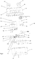
Figure 1 shows a perspective sectional view of a gas meter according to the invention; -
Figure 2 shows a perspective exploded view of a gas meter according to the invention; -
Figure 3 shows a side sectional view of a gas meter according to the invention; -
Figure 4 shows a detail of the side sectional view ofFigure 3 ; -
Figure 5 shows a perspective sectional view of a variant embodiment of the gas meter according to the invention; -
Figure 6 shows a perspective sectional view of a further variant embodiment of the gas meter according to the invention. - With reference to the figures mentioned above, a gas meter according to the invention is indicated as a whole by the
numeral 10. - Said
gas meter 10 comprises - a box-
shaped body 11, - an
inlet mouth 15 and anoutlet mouth 16 designed to allow the passage of a gas flow and defined on the box-shaped body 11. - Inside the box-
shaped body 11 there is ametering device 19 designed to measure one or more parameters for the determination of the gas flow rate; thismetering device 19, too, is provided with an inlet opening 19a and an outlet opening 19b of its own. - The specific characteristic of the
gas meter 10 according to the invention lies in that it comprises: - an
inlet duct 25 extending from saidinlet mouth 15 towards anopposite side 13 of the box-shaped body 11, - an
outlet duct 40 extending between theoutlet mouth 16 and anopposite side 13 of the box-shaped body 11. - The
metering device 19 is positioned in an intermediate area between theinlet duct 25 and theoutlet duct 40. - The term 'intermediate area' is used to indicate the space included between the
inlet duct 25 and theoutlet duct 40 inside the box-shaped body 11. - The
metering device 19 must therefore be intended as suited to be positioned in any point and with any configuration in said space included between theinlet duct 25 and theoutlet duct 40. - Inside the box-
shaped body 11 there are means 20 configured in such a way as to deviate the gas flowing out through the outlet opening 19b of themetering device 19 towards an inlet opening 40a of theoutlet duct 40. - As clearly visible in
Figure 3 , said means 20, configured in such a way as to deviate the gas flowing out through the outlet opening 19b of themetering device 19 towards the inlet opening 40a of theoutlet duct 40, define a trajectory X3 comprising a deviation that develops over adeviation angle 21 between a direction X1 crossing themetering device 19 and a direction X2 crossing theoutlet duct 40, saiddeviation angle 21 being included in an interval ranging between a neighbourhood of 90° and 225°. - The expression 'neighbourhood of 90°' is used to indicate an interval between -15° and +15° with respect to 90°.
- Said
deviation angle 21 is preferably included between 91° and 225°. - More specifically, said
deviation angle 21 is equal to 180°, as clearly visible inFigures 3 and4 . - In the present example of embodiment, the box-
shaped body 11 comprises, with respect to a normal configuration of use, atop side 12, anopposite bottom side 13 and aside wall 14. - The
outlet mouth 16 is defined on thetop side 12. Theinlet mouth 15 and theoutlet mouth 16 are defined on thetop side 12. - It must be understood that the
inlet mouth 15 and theoutlet mouth 16 can both be provided, in an example not being part of the present invention, on another, yet the same, side different from thetop side 12. - It must be understood that the
inlet mouth 15 and theoutlet mouth 16 can each be provided, in an example not being part of the present invention, on a respective side of the box-shaped body 11, different from the side on which the other mouth is provided. - In the preferred variant embodiment, the
gas meter 10 comprises also an on-offvalve 18 suited to intercept the gas flow across thegas meter 10, said on-offvalve 18 being provided with an inlet opening 18a and an outlet opening 18b. - In the present example of embodiment, the on-off
valve 18 is located at the level of theoutlet mouth 16 of the box-shaped body 11. - The on-off
valve 18 is a part of theoutlet duct 40. - In the present example of embodiment, the
gas meter 10 comprises a first threadedconnection element 23 at the level of theinlet mouth 15 of the box-shaped body 11 and a second threadedconnection element 24 at the level of theoutlet mouth 16 of the box-shaped body 11. - The
gas meter 10 comprises also filtering means 17 suited to filter the gas flow. - Said filtering means 17 comprise a
dust deposit chamber 26 defined between thebottom side 13 of the box-shaped body 11 and amechanical filtering partition 27 interposed between thebottom side 13 and thetop side 12. - Said
mechanical filtering partition 27 comprises amesh portion 28. - Said
mesh portion 28 has throughopenings 28a; the dimensions of said throughopenings 28a are such as to prevent the passage of dust particles with particularly large diameter, meaning that said throughopenings 28a have a cross section whose main dimension, for example their side if they are square in shape or their diameter if they are round in shape, is included between 0.5 and 3 mm, and preferably is equal to 1 mm. - In a variant embodiment of the invention, the
mesh portion 28 may comprise several filtering layers, sandwich-layered or spaced from one another, each layer being constituted by a mesh or a net or a non-woven fabric. - The
inlet duct 25 extends from theinlet mouth 15 of the box-shaped body 11 to the inside of thedust deposit chamber 26. - Said
inlet duct 25 is configured in such a way that the gas flow entering through the first threadedconnection element 23 is not dispersed in the inner compartment of the box-shaped body 11 but is directly and completely conveyed into thedust deposit chamber 26. - Then, the
mechanical filtering partition 27 is provided with athrough hole 27a configured so that theinlet duct 25 can pass through it. - Said
dust deposit chamber 26 is configured in such a way that the gas flow coming from theinlet duct 25 can exit from it only through themesh portion 28 of themechanical filtering partition 27. - In the present embodiment, the
metering device 19 is positioned, as mentioned above, in an intermediate area between theoutlet duct 40 and theinlet duct 25, beside both theoutlet duct 40 and theinlet duct 25. - In said intermediate position, and thanks to the
means 20 for deviating the gas flow that exits from the outlet opening 19b of themetering device 19 and is directed towards the inlet opening 40a of theoutlet duct 40, themetering device 19 is substantially inaccessible in case of any tampering attempt made both through theoutlet mouth 16 and through theinlet mouth 15 of the box-shaped body 11, if this should be the case. - In fact, due to the presence of the
inlet duct 25 and themechanical filtering partition 27, on the one hand, and of theoutlet duct 40 and the flow deviation means 20, on the other hand, themetering device 19 is substantially positioned at the centre of a maze-like route that cannot be accessed using the currently known break-in tools. - In the present example of embodiment, the
inlet duct 25 is constituted by a tubular element that extends along a crossing direction X4. - The crossing direction X4 is preferably parallel to the crossing direction X1 of the
metering device 19 and the crossing direction X2 of theoutlet duct 40. - In the present example of embodiment, the
outlet duct 40 comprises: - an
entry section 40b, in turn comprising theinlet opening 40a, - an
exit section 40c, - the on-off
valve 18, interposed between theentry section 40b and theexit section 40c. - The on-off
valve 18 is connected to theentry section 40b and to theexit section 40c in such a way that it is coaxial with both of them. - The
exit section 40c is constituted by a sleeve positioned in such a way that it passes through theoutlet mouth 16 and connects with the second threadedconnection element 24. - The
metering device 19, for example, is a flow rate meter of the static type. Saidmetering device 19 may comprise - a
transit pipe 30 designed to allow the transit of the gas flow and including theinlet opening 19a and theoutlet opening 19b, and inside which real sensors are provided, - and an intercepting
projection 31 positioned outside thetransit pipe 30 and designed to meet the gas flow coming from themesh portion 28. - Said intercepting
projection 31 is constituted, for example, by a flat element extending from thetransit pipe 30 according to a reference plane lying crosswise with respect to the flowing direction of the gas flow. - In a variant embodiment of the invention, the
metering device 19 comprises an electronic interface unit that is external to thetransit pipe 30 and is configured in such a way that it can receive the metering signals emitted by the sensors, transmit them to a remote control unit and power the sensors. - More specifically, in the present example of embodiment of the
gas meter 10 according to the invention, themetering device 19 is positioned with its crossing direction X1 parallel to the crossing direction X2 of theoutlet duct 40. More specifically, themetering device 19 is positioned with theinlet opening 19a in proximity to thetop side 12 of the box-shapedbody 11. Theinlet opening 19a faces upwards with respect to a normal configuration of use of thegas meter 10. - Thus, the
metering device 19 is positioned with theinlet opening 19a facing towards thetop side 12 of the box-shapedbody 11 with respect to a normal configuration of use. - Even more specifically, the
metering device 19 is positioned in such a way that the interceptingprojection 31, or the electronic interface unit, is arranged above themesh portion 28; in this way, the interceptingprojection 31 contributes to deviating the gas flow, leading to the consequent accumulation of any dust residues present in the gas flow on the surface of the interceptingprojection 31 itself or on the surface of the casing containing the electronic interface unit. - In this specific configuration of the
gas meter 10, themechanical filtering partition 27 is interposed between thebottom side 13 and the inlet opening 19a of themetering device 19. - More specifically, the
mechanical filtering partition 27 is interposed between thebottom side 13 and the casing containing theelectronic interface unit 31 of themetering device 19. - In the present example of embodiment, the
mechanical filtering partition 27 is provided withperimeter sealing edges 65 that are configured in such a way as to be placed in contact with the inner surface of the box-shapedbody 11 and press against it, thus ensuring tightness against the passage of gas containing fine dust. - In the embodiment of the invention described herein by way of non-limiting example of the invention itself, the
means 20, which are configured to deviate the gas flow that exits from the outlet opening 19b of themetering device 19 towards the inlet opening 40a of theoutlet duct 40, comprise ahollow body 50 inside which adeviation chamber 51 is defined. - In the present example of embodiment, the
hollow body 50 comprises: - a joining
collar 52 suitable for connection with the outlet opening 19b of themetering device 19, - and the
entry section 40b of theoutlet duct 40. - Both the joining
collar 52 and theentry section 40b are obviously open and in communication with thedeviation chamber 51. - In the present example of embodiment, the
hollow body 50 is constituted by acontainer 53 closed by a shapedcover 54. - The joining
collar 52 and theentry section 40b are defined on the shapedcover 54. - The
container 53 has afirst rest edge 55 where a correspondingsecond rest edge 56 of the shapedcover 54 can be rested. - Said
first rest edge 55 andsecond rest edge 56 are sealed together, for example by means of a heat welding operation. - Said
hollow body 50 is positioned in proximity to thebottom side 13 of the box-shapedbody 11. - The
metering device 19, the gas flow deviation means 20 and theoutlet duct 40 are connected to one another in such a way as to define a tight path configured to prevent the leakage of the gas flow already measured through themetering device 19. - More specifically:
- the outlet opening 19b of the
metering device 19 and the joiningcollar 52 of thehollow body 50 are connected, with at least one sealingring 60 interposed therebetween; - the
entry section 40b of theoutlet duct 40 and theinlet mouth 18a of the on-offvalve 18 are coupled together, with at least one sealingring 61 interposed therebetween; - the
outlet mouth 18b of the on-offvalve 18 and theexit section 40c are coupled together, with at least one sealingring 62 interposed therebetween; - the
exit section 40c and the second threadedconnection element 24 are coupled together, with at least one sealingring 63 interposed therebetween. - Thanks to this sequence of tight connections, the measured gas flow that exits from the
metering device 19 cannot return into the inner compartment of the box-shapedbody 11 and cannot be measured again by mistake. - The
mechanical filtering partition 27 extends from thehollow body 50, and more specifically it extends from the shapedcover 54. - More specifically, said
mechanical filtering partition 27 forms a single body with the shapedcover 54. - In the present example of embodiment, the box-shaped
body 11 comprises two half-shells -
Figure 5 shows a variant embodiment of the gas meter according to the invention, indicated by the numeral 110. - In this variant embodiment, analogously to what has been described above with reference to the preferred embodiment, the
gas meter 110 comprises: - a box-shaped
body 111, - an
inlet mouth 115 and anoutlet mouth 116 suited to allow the passage of a gas flow and defined on the box-shapedbody 111, - an on-off
valve 118 suited to intercept the gas flow through thegas meter 110, - and a
metering device 119 suited to measure one or more parameters for the determination of the gas flow rate; - an
inlet duct 125 extending from saidinlet mouth 115 towards anopposite side 113 of the box-shapedbody 111, - an
outlet duct 140 extending between theoutlet mouth 116 and anopposite side 113 of the box-shapedbody 111, - In this variant embodiment, the on-off
valve 118 is placed at the level of saidinlet mouth 115 of the box-shapedbody 111. - The on-off
valve 118 is a part of theinlet duct 125. - Filtering means 117 are provided, analogously to what has been described above with reference to the filtering means 17.
- In this variant embodiment, the
outlet duct 140 is constituted by a tubular element that extends according to a crossing direction X2. - The on-off
valve -
Figure 6 shows a further variant embodiment of the gas meter according to the invention, indicated by the numeral 210. - In this variant embodiment, analogously to what has been described above with reference to the preferred embodiment, the
gas meter 210 comprises: - a box-shaped
body 211, - an
inlet mouth 215 and anoutlet mouth 216 suited to allow the passage of a gas flow and defined on the box-shapedbody 211, - an
inlet duct 225 extending from saidinlet mouth 215 towards anopposite side 213 of the box-shapedbody 211, - an
outlet duct 240 extending between theoutlet mouth 216 and anopposite side 213 of the box-shapedbody 211, - In said variant embodiment, the on-off valve is not provided.
- Filtering means 217 are provided, analogously to what has been described above with reference to the filtering means 17.
- In this variant embodiment, the
inlet duct 225 is constituted by a first tubular element and theoutlet duct 240 is constituted by a second tubular element. - It has thus been ascertained that the invention achieves the set purpose and objects.
- More specifically, the invention provides a
gas meter 10 that, in comparison with the meters known in the art, is capable of considerably reducing the risks of fraud due to tampering with themetering device 19 from the outside, for example in the case where an attempt should be made to access the metering device through the connection elements using a tool designed to hinder the operation of the sensors present in the metering device. - Furthermore, thanks to the filtering means 17 comprising a
dust deposit chamber 26 designed to hold back the dust and defined between thebottom side 13 of the box-shapedbody 11 and amechanical filtering partition 27, the gas meter according to the invention is configured in such a way as to prevent the dust present in the gas flow from being transported towards the metering device and even towards the on-offvalve 18 by the main gas flow; in this way, the metering and functional performance of the valve is guaranteed and constant over time. - The filtering system is made up in such a way as to collect the dust in a space positioned on the bottom of the meter and perimetrically delimited by sealing edges that prevent the upward flow of gas that has not been filtered by the
mesh portion 28. - Furthermore, in our case, the sizing of the total surface area of the through openings of the
mesh portion 28 has been carried out trying to identify the optimal balance between the filtering action exerted on the particles and the minimization of the flow resistance intrinsic in the system, while in the known art the difference in pressure between the inlet and the outlet of the gas meter itself keeps increasing as a consequence of the accumulation of particles on the filter during the useful life of the gas meter. - Moreover, in the gas meter according to the present invention, the pressurized gas flow, once filtered, moves upwards towards the top of the box-shaped
body 11, where there is the inlet opening 19a of themetering device 19 for the measurement of the flow rate; this position, which is high with respect to thedust deposit chamber 26, is such that during the upward flow of the gas only the lighter particles reach themetering device 19, while the heavier granules fall towards the bottom of the meter due to gravity or adhere to its sides; in this way, themetering device 19 and even more obviously the on-offvalve 18, which is the last element of the chain through which the gas flows before exiting from thegas meter 10, are protected against the fouling action of the gas. - The invention as conceived can be subjected to several changes and modifications, all falling within the inventive concept illustrated herein; furthermore, all the details and elements can be replaced by other technically equivalent details and elements.
- In practice, any components and any materials can be used, provided that they are compatible with the intended use, and likewise any size and shape can be selected, according to the needs and the state of the art.
- Where the characteristics and techniques mentioned in any of the claims are followed by reference signs, it must be understood that these reference signs are used only for the purpose of making the claims easier to understand, consequently these reference signs do not have any limiting effect on the function and meaning of any element identified by the same reference signs by way of example.
Claims (7)
- Gas meter (10), comprising:- a box-shaped body (11), said box-shaped body (11) comprising, with respect to a normal configuration of use, a top side (12), an opposite bottom side (13) and a side wall (14),- an inlet mouth (15) and an outlet mouth (16) suited to allow the passage of a gas flow and defined on said box-shaped body (11), said inlet mouth (15) and said outlet mouth (16) being defined on said top side (12),wherein inside said box-shaped body (11) there is a metering device (19) designed to measure one or more parameters for the determination of the gas flow rate, said metering device (19) being provided with an inlet opening (19a) and an outlet opening (19b),characterized in that the gas meter (10) comprises:- an inlet duct (25) extending from said inlet mouth (15) towards said opposite bottom side (13) of said box-shaped body (11),- an outlet duct (40) extending between said outlet mouth (16) and said opposite bottom side (13) of said box-shaped body (11),said metering device (19) being positioned in an intermediate area between said inlet duct (25) and said outlet duct (40),said metering device (19) being positioned with said inlet opening (19a) facing towards the top side (12) of the box-shaped body (11) with respect to a normal configuration of use,the gas meter (10) further comprising means (20) configured to deviate the gas flow that exits from said outlet opening (19b) of said metering device (19) towards an inlet opening (40a) of said outlet duct (40), thereby creating a tight path between the metering device (19) and the outlet duct (40).
- Gas meter according to claim 1, characterized in that said inlet duct (25) is constituted by a tubular element that extends along a crossing direction (X4), said crossing direction (X4) being parallel to a crossing direction (X1) of the metering device (19) and a crossing direction (X2) of the outlet duct (40).
- Gas meter according to the preceding claim, characterized in that said means (20), which are configured to deviate the gas flow that exits from said outlet opening (19b) of said metering device (19) and is directed towards said inlet opening (40a) of said outlet duct (40), define a trajectory (X3) comprising a deviation that extends over a deviation angle (21) between a direction (X1) crossing said metering device (19) and a direction (X2) crossing said outlet duct (40), said deviation angle (21) being included within an interval between a range of -15° and +15° with respect to 90° and 225°.
- Gas meter according to claim 1 or 2, characterized in that said means (20), which are configured to deviate the gas flow that exits from the outlet opening (19b) of the metering device (19) towards the inlet opening (40a) of the outlet duct (40), comprise a hollow body (50) inside which a deviation chamber (51) is defined, said hollow body (50) comprising:- a joining collar (52) suitable for connection with the outlet opening (19b) of the metering device (19),- and an entry section (40b) of the outlet duct (40).
- Gas meter according to one or more of the claims 3 and 4, characterized in that said deviation angle (21) is equal to 180°.
- Gas meter according to one or more of the preceding claims, characterized in that it comprises an on-off valve (18).
- Gas meter according to one or more of the preceding claims, characterized in that said metering device (19) is positioned with said inlet opening (19a) placed in proximity to the top side (12) of the box-shaped body (11) with respect to a normal configuration of use.
Applications Claiming Priority (2)
| Application Number | Priority Date | Filing Date | Title |
|---|---|---|---|
| IT102018000006409A IT201800006409A1 (en) | 2018-06-18 | 2018-06-18 | GAS METER |
| PCT/IB2019/055052 WO2019244005A1 (en) | 2018-06-18 | 2019-06-17 | Gas meter |
Publications (2)
| Publication Number | Publication Date |
|---|---|
| EP3807602A1 EP3807602A1 (en) | 2021-04-21 |
| EP3807602B1 true EP3807602B1 (en) | 2022-11-30 |
Family
ID=63579673
Family Applications (1)
| Application Number | Title | Priority Date | Filing Date |
|---|---|---|---|
| EP19742486.4A Active EP3807602B1 (en) | 2018-06-18 | 2019-06-17 | Gas meter |
Country Status (6)
| Country | Link |
|---|---|
| US (1) | US11796369B2 (en) |
| EP (1) | EP3807602B1 (en) |
| CN (1) | CN112334741B (en) |
| IT (1) | IT201800006409A1 (en) |
| PL (1) | PL3807602T3 (en) |
| WO (1) | WO2019244005A1 (en) |
Families Citing this family (4)
| Publication number | Priority date | Publication date | Assignee | Title |
|---|---|---|---|---|
| FR3146203B1 (en) * | 2023-02-28 | 2025-04-11 | Sagemcom Energy & Telecom Sas | Dust filter for gas meter |
| USD1099729S1 (en) * | 2024-05-10 | 2025-10-28 | Honeywell International Inc. | Proximal flow sensor |
| USD1100697S1 (en) * | 2024-07-29 | 2025-11-04 | Honeywell International Inc. | Proximal flow sensor |
| USD1099730S1 (en) * | 2024-07-29 | 2025-10-28 | Honeywell International Inc. | Proximal flow sensor |
Family Cites Families (16)
| Publication number | Priority date | Publication date | Assignee | Title |
|---|---|---|---|---|
| JPS4839746B1 (en) * | 1969-03-20 | 1973-11-27 | ||
| US4406163A (en) * | 1982-01-18 | 1983-09-27 | Lofink Joseph P | Positive displacement volumetric compressible fluid meter |
| AUPP282998A0 (en) * | 1998-04-07 | 1998-04-30 | Email Limited | Gas meter & regulator combination |
| CN1515878A (en) | 1998-08-18 | 2004-07-28 | ͬ�Ϳ�ҵ��ʽ���� | Flow sensor and filter integrated flowmeter |
| GB2341688A (en) * | 1998-09-19 | 2000-03-22 | Siemens Measurements Ltd | Adaptable gas meter |
| DE102010047680A1 (en) * | 2010-10-06 | 2012-04-12 | Hydrometer Gmbh | gas Meter |
| DE102010051594B4 (en) * | 2010-11-16 | 2013-04-11 | Hydrometer Gmbh | gas Meter |
| JP2014157016A (en) * | 2011-06-10 | 2014-08-28 | Panasonic Corp | Gas meter |
| DE102011115768B4 (en) * | 2011-10-12 | 2014-05-08 | Hydrometer Gmbh | gas Meter |
| EP2813824B1 (en) * | 2013-06-12 | 2019-04-17 | Itron GmbH | Gas meter and particle trap |
| CN203561399U (en) * | 2013-09-18 | 2014-04-23 | 廊坊新奥燃气设备有限公司 | Combustion gas meter |
| US9612146B2 (en) * | 2014-02-07 | 2017-04-04 | Honeywell International, Inc. | Airflow sensor with dust reduction |
| CN203964971U (en) * | 2014-07-28 | 2014-11-26 | 北京嘉洁能科技有限公司 | Bicavate ultrasonic wave gas meter |
| US9784607B2 (en) * | 2016-02-24 | 2017-10-10 | M-Tech Instrument Corporation Holding Limited | Utility mass flow gas meter |
| EP3296704A1 (en) * | 2016-09-16 | 2018-03-21 | Energoflow AG | Flowmeter |
| IT201800006413A1 (en) * | 2018-06-18 | 2019-12-18 | STRUCTURE OF GAS METER |
-
2018
- 2018-06-18 IT IT102018000006409A patent/IT201800006409A1/en unknown
-
2019
- 2019-06-17 EP EP19742486.4A patent/EP3807602B1/en active Active
- 2019-06-17 PL PL19742486.4T patent/PL3807602T3/en unknown
- 2019-06-17 CN CN201980040870.2A patent/CN112334741B/en active Active
- 2019-06-17 WO PCT/IB2019/055052 patent/WO2019244005A1/en not_active Ceased
- 2019-06-17 US US17/056,326 patent/US11796369B2/en active Active
Also Published As
| Publication number | Publication date |
|---|---|
| US11796369B2 (en) | 2023-10-24 |
| IT201800006409A1 (en) | 2019-12-18 |
| US20210278267A1 (en) | 2021-09-09 |
| EP3807602A1 (en) | 2021-04-21 |
| CN112334741B (en) | 2025-02-11 |
| PL3807602T3 (en) | 2023-04-11 |
| WO2019244005A1 (en) | 2019-12-26 |
| CN112334741A (en) | 2021-02-05 |
Similar Documents
| Publication | Publication Date | Title |
|---|---|---|
| EP3807601B1 (en) | Gas meter structure | |
| US11796369B2 (en) | Gas meter having a static metering device therein for measuring the gas flow and prevent tampering | |
| US5280802A (en) | Gas appliance detection apparatus | |
| US5085076A (en) | Integrated water strainer, meter, and crossover check valve | |
| EP3200882B1 (en) | Flame arresters | |
| CN105960583B (en) | Improvements in respiratory sampling systems | |
| US9671269B2 (en) | Gas meter and particle trap | |
| US20210046342A1 (en) | System, apparatus & method for arresting propagation of a deflagration in a clean air return duct of an air-material separator | |
| RU2019118968A (en) | AIR CONDUCTING STRUCTURE ELEMENT | |
| AU2013371655B2 (en) | Water meter including variable orifice device | |
| WO2008027892A3 (en) | Additive dispersing filter and method of making | |
| JP2016516203A (en) | Sensor device for detecting the humidity of a flowing fluid medium | |
| US20240247962A1 (en) | Gas meter | |
| EP3047892B1 (en) | Inline pre-filter for aspiration detectors | |
| EP4724777A1 (en) | An improved gas meter | |
| JP6033163B2 (en) | Flowmeter | |
| KR200462043Y1 (en) | Collcting condensation drain plugs had for explosion- proof devirs exhaust and ventilation function | |
| US1646513A (en) | Water-line trap | |
| US11103818B2 (en) | Filter device and water heater | |
| TR2023017383U5 (en) | SAFETY COVER THAT PROVIDES PROTECTION AGAINST FREEZING FOR WATER METERS | |
| CN206573547U (en) | A kind of bleeder is poisonous or fuel gas detecting system | |
| KR101994917B1 (en) | Detector for ingredient of gas and duct unit including the same | |
| JPH0348099A (en) | Abnormality detecting device for steam pipe | |
| CN105092100A (en) | Heat meter with detection and filtering functions | |
| JP2014232013A (en) | Heavy oil leakage detection device |
Legal Events
| Date | Code | Title | Description |
|---|---|---|---|
| STAA | Information on the status of an ep patent application or granted ep patent |
Free format text: STATUS: UNKNOWN |
|
| STAA | Information on the status of an ep patent application or granted ep patent |
Free format text: STATUS: THE INTERNATIONAL PUBLICATION HAS BEEN MADE |
|
| PUAI | Public reference made under article 153(3) epc to a published international application that has entered the european phase |
Free format text: ORIGINAL CODE: 0009012 |
|
| STAA | Information on the status of an ep patent application or granted ep patent |
Free format text: STATUS: REQUEST FOR EXAMINATION WAS MADE |
|
| 17P | Request for examination filed |
Effective date: 20201123 |
|
| AK | Designated contracting states |
Kind code of ref document: A1 Designated state(s): AL AT BE BG CH CY CZ DE DK EE ES FI FR GB GR HR HU IE IS IT LI LT LU LV MC MK MT NL NO PL PT RO RS SE SI SK SM TR |
|
| AX | Request for extension of the european patent |
Extension state: BA ME |
|
| RIN1 | Information on inventor provided before grant (corrected) |
Inventor name: IMBOCCIOLI, CLAUDIO Inventor name: GHIDINA, MARCELLO Inventor name: VIANELLO, MARIO |
|
| DAV | Request for validation of the european patent (deleted) | ||
| DAX | Request for extension of the european patent (deleted) | ||
| GRAP | Despatch of communication of intention to grant a patent |
Free format text: ORIGINAL CODE: EPIDOSNIGR1 |
|
| STAA | Information on the status of an ep patent application or granted ep patent |
Free format text: STATUS: GRANT OF PATENT IS INTENDED |
|
| INTG | Intention to grant announced |
Effective date: 20220203 |
|
| GRAJ | Information related to disapproval of communication of intention to grant by the applicant or resumption of examination proceedings by the epo deleted |
Free format text: ORIGINAL CODE: EPIDOSDIGR1 |
|
| STAA | Information on the status of an ep patent application or granted ep patent |
Free format text: STATUS: REQUEST FOR EXAMINATION WAS MADE |
|
| GRAP | Despatch of communication of intention to grant a patent |
Free format text: ORIGINAL CODE: EPIDOSNIGR1 |
|
| STAA | Information on the status of an ep patent application or granted ep patent |
Free format text: STATUS: GRANT OF PATENT IS INTENDED |
|
| INTC | Intention to grant announced (deleted) | ||
| INTG | Intention to grant announced |
Effective date: 20220622 |
|
| GRAS | Grant fee paid |
Free format text: ORIGINAL CODE: EPIDOSNIGR3 |
|
| GRAA | (expected) grant |
Free format text: ORIGINAL CODE: 0009210 |
|
| STAA | Information on the status of an ep patent application or granted ep patent |
Free format text: STATUS: THE PATENT HAS BEEN GRANTED |
|
| AK | Designated contracting states |
Kind code of ref document: B1 Designated state(s): AL AT BE BG CH CY CZ DE DK EE ES FI FR GB GR HR HU IE IS IT LI LT LU LV MC MK MT NL NO PL PT RO RS SE SI SK SM TR |
|
| REG | Reference to a national code |
Ref country code: CH Ref legal event code: EP Ref country code: GB Ref legal event code: FG4D |
|
| REG | Reference to a national code |
Ref country code: AT Ref legal event code: REF Ref document number: 1534998 Country of ref document: AT Kind code of ref document: T Effective date: 20221215 |
|
| REG | Reference to a national code |
Ref country code: IE Ref legal event code: FG4D |
|
| REG | Reference to a national code |
Ref country code: DE Ref legal event code: R096 Ref document number: 602019022567 Country of ref document: DE |
|
| REG | Reference to a national code |
Ref country code: NL Ref legal event code: FP |
|
| REG | Reference to a national code |
Ref country code: LT Ref legal event code: MG9D |
|
| PG25 | Lapsed in a contracting state [announced via postgrant information from national office to epo] |
Ref country code: SE Free format text: LAPSE BECAUSE OF FAILURE TO SUBMIT A TRANSLATION OF THE DESCRIPTION OR TO PAY THE FEE WITHIN THE PRESCRIBED TIME-LIMIT Effective date: 20221130 Ref country code: PT Free format text: LAPSE BECAUSE OF FAILURE TO SUBMIT A TRANSLATION OF THE DESCRIPTION OR TO PAY THE FEE WITHIN THE PRESCRIBED TIME-LIMIT Effective date: 20230331 Ref country code: NO Free format text: LAPSE BECAUSE OF FAILURE TO SUBMIT A TRANSLATION OF THE DESCRIPTION OR TO PAY THE FEE WITHIN THE PRESCRIBED TIME-LIMIT Effective date: 20230228 Ref country code: LT Free format text: LAPSE BECAUSE OF FAILURE TO SUBMIT A TRANSLATION OF THE DESCRIPTION OR TO PAY THE FEE WITHIN THE PRESCRIBED TIME-LIMIT Effective date: 20221130 Ref country code: FI Free format text: LAPSE BECAUSE OF FAILURE TO SUBMIT A TRANSLATION OF THE DESCRIPTION OR TO PAY THE FEE WITHIN THE PRESCRIBED TIME-LIMIT Effective date: 20221130 Ref country code: ES Free format text: LAPSE BECAUSE OF FAILURE TO SUBMIT A TRANSLATION OF THE DESCRIPTION OR TO PAY THE FEE WITHIN THE PRESCRIBED TIME-LIMIT Effective date: 20221130 |
|
| REG | Reference to a national code |
Ref country code: AT Ref legal event code: MK05 Ref document number: 1534998 Country of ref document: AT Kind code of ref document: T Effective date: 20221130 |
|
| PG25 | Lapsed in a contracting state [announced via postgrant information from national office to epo] |
Ref country code: RS Free format text: LAPSE BECAUSE OF FAILURE TO SUBMIT A TRANSLATION OF THE DESCRIPTION OR TO PAY THE FEE WITHIN THE PRESCRIBED TIME-LIMIT Effective date: 20221130 Ref country code: LV Free format text: LAPSE BECAUSE OF FAILURE TO SUBMIT A TRANSLATION OF THE DESCRIPTION OR TO PAY THE FEE WITHIN THE PRESCRIBED TIME-LIMIT Effective date: 20221130 Ref country code: IS Free format text: LAPSE BECAUSE OF FAILURE TO SUBMIT A TRANSLATION OF THE DESCRIPTION OR TO PAY THE FEE WITHIN THE PRESCRIBED TIME-LIMIT Effective date: 20230330 Ref country code: HR Free format text: LAPSE BECAUSE OF FAILURE TO SUBMIT A TRANSLATION OF THE DESCRIPTION OR TO PAY THE FEE WITHIN THE PRESCRIBED TIME-LIMIT Effective date: 20221130 Ref country code: GR Free format text: LAPSE BECAUSE OF FAILURE TO SUBMIT A TRANSLATION OF THE DESCRIPTION OR TO PAY THE FEE WITHIN THE PRESCRIBED TIME-LIMIT Effective date: 20230301 |
|
| PG25 | Lapsed in a contracting state [announced via postgrant information from national office to epo] |
Ref country code: SM Free format text: LAPSE BECAUSE OF FAILURE TO SUBMIT A TRANSLATION OF THE DESCRIPTION OR TO PAY THE FEE WITHIN THE PRESCRIBED TIME-LIMIT Effective date: 20221130 Ref country code: RO Free format text: LAPSE BECAUSE OF FAILURE TO SUBMIT A TRANSLATION OF THE DESCRIPTION OR TO PAY THE FEE WITHIN THE PRESCRIBED TIME-LIMIT Effective date: 20221130 Ref country code: EE Free format text: LAPSE BECAUSE OF FAILURE TO SUBMIT A TRANSLATION OF THE DESCRIPTION OR TO PAY THE FEE WITHIN THE PRESCRIBED TIME-LIMIT Effective date: 20221130 Ref country code: DK Free format text: LAPSE BECAUSE OF FAILURE TO SUBMIT A TRANSLATION OF THE DESCRIPTION OR TO PAY THE FEE WITHIN THE PRESCRIBED TIME-LIMIT Effective date: 20221130 Ref country code: CZ Free format text: LAPSE BECAUSE OF FAILURE TO SUBMIT A TRANSLATION OF THE DESCRIPTION OR TO PAY THE FEE WITHIN THE PRESCRIBED TIME-LIMIT Effective date: 20221130 Ref country code: AT Free format text: LAPSE BECAUSE OF FAILURE TO SUBMIT A TRANSLATION OF THE DESCRIPTION OR TO PAY THE FEE WITHIN THE PRESCRIBED TIME-LIMIT Effective date: 20221130 |
|
| PG25 | Lapsed in a contracting state [announced via postgrant information from national office to epo] |
Ref country code: SK Free format text: LAPSE BECAUSE OF FAILURE TO SUBMIT A TRANSLATION OF THE DESCRIPTION OR TO PAY THE FEE WITHIN THE PRESCRIBED TIME-LIMIT Effective date: 20221130 Ref country code: AL Free format text: LAPSE BECAUSE OF FAILURE TO SUBMIT A TRANSLATION OF THE DESCRIPTION OR TO PAY THE FEE WITHIN THE PRESCRIBED TIME-LIMIT Effective date: 20221130 |
|
| REG | Reference to a national code |
Ref country code: DE Ref legal event code: R097 Ref document number: 602019022567 Country of ref document: DE |
|
| PLBE | No opposition filed within time limit |
Free format text: ORIGINAL CODE: 0009261 |
|
| STAA | Information on the status of an ep patent application or granted ep patent |
Free format text: STATUS: NO OPPOSITION FILED WITHIN TIME LIMIT |
|
| 26N | No opposition filed |
Effective date: 20230831 |
|
| PG25 | Lapsed in a contracting state [announced via postgrant information from national office to epo] |
Ref country code: SI Free format text: LAPSE BECAUSE OF FAILURE TO SUBMIT A TRANSLATION OF THE DESCRIPTION OR TO PAY THE FEE WITHIN THE PRESCRIBED TIME-LIMIT Effective date: 20221130 |
|
| PG25 | Lapsed in a contracting state [announced via postgrant information from national office to epo] |
Ref country code: MC Free format text: LAPSE BECAUSE OF FAILURE TO SUBMIT A TRANSLATION OF THE DESCRIPTION OR TO PAY THE FEE WITHIN THE PRESCRIBED TIME-LIMIT Effective date: 20221130 |
|
| PG25 | Lapsed in a contracting state [announced via postgrant information from national office to epo] |
Ref country code: MC Free format text: LAPSE BECAUSE OF FAILURE TO SUBMIT A TRANSLATION OF THE DESCRIPTION OR TO PAY THE FEE WITHIN THE PRESCRIBED TIME-LIMIT Effective date: 20221130 |
|
| REG | Reference to a national code |
Ref country code: CH Ref legal event code: PL |
|
| REG | Reference to a national code |
Ref country code: BE Ref legal event code: MM Effective date: 20230630 |
|
| GBPC | Gb: european patent ceased through non-payment of renewal fee |
Effective date: 20230617 |
|
| PG25 | Lapsed in a contracting state [announced via postgrant information from national office to epo] |
Ref country code: LU Free format text: LAPSE BECAUSE OF NON-PAYMENT OF DUE FEES Effective date: 20230617 |
|
| REG | Reference to a national code |
Ref country code: IE Ref legal event code: MM4A |
|
| PG25 | Lapsed in a contracting state [announced via postgrant information from national office to epo] |
Ref country code: LU Free format text: LAPSE BECAUSE OF NON-PAYMENT OF DUE FEES Effective date: 20230617 |
|
| PG25 | Lapsed in a contracting state [announced via postgrant information from national office to epo] |
Ref country code: IE Free format text: LAPSE BECAUSE OF NON-PAYMENT OF DUE FEES Effective date: 20230617 |
|
| PG25 | Lapsed in a contracting state [announced via postgrant information from national office to epo] |
Ref country code: IE Free format text: LAPSE BECAUSE OF NON-PAYMENT OF DUE FEES Effective date: 20230617 Ref country code: GB Free format text: LAPSE BECAUSE OF NON-PAYMENT OF DUE FEES Effective date: 20230617 Ref country code: CH Free format text: LAPSE BECAUSE OF NON-PAYMENT OF DUE FEES Effective date: 20230630 |
|
| PG25 | Lapsed in a contracting state [announced via postgrant information from national office to epo] |
Ref country code: BE Free format text: LAPSE BECAUSE OF NON-PAYMENT OF DUE FEES Effective date: 20230630 |
|
| PG25 | Lapsed in a contracting state [announced via postgrant information from national office to epo] |
Ref country code: BG Free format text: LAPSE BECAUSE OF FAILURE TO SUBMIT A TRANSLATION OF THE DESCRIPTION OR TO PAY THE FEE WITHIN THE PRESCRIBED TIME-LIMIT Effective date: 20221130 |
|
| PG25 | Lapsed in a contracting state [announced via postgrant information from national office to epo] |
Ref country code: BG Free format text: LAPSE BECAUSE OF FAILURE TO SUBMIT A TRANSLATION OF THE DESCRIPTION OR TO PAY THE FEE WITHIN THE PRESCRIBED TIME-LIMIT Effective date: 20221130 |
|
| PGFP | Annual fee paid to national office [announced via postgrant information from national office to epo] |
Ref country code: PL Payment date: 20250606 Year of fee payment: 7 Ref country code: DE Payment date: 20250618 Year of fee payment: 7 |
|
| PGFP | Annual fee paid to national office [announced via postgrant information from national office to epo] |
Ref country code: NL Payment date: 20250618 Year of fee payment: 7 Ref country code: IT Payment date: 20250402 Year of fee payment: 7 |
|
| PGFP | Annual fee paid to national office [announced via postgrant information from national office to epo] |
Ref country code: FR Payment date: 20250627 Year of fee payment: 7 |
|
| PG25 | Lapsed in a contracting state [announced via postgrant information from national office to epo] |
Ref country code: CY Free format text: LAPSE BECAUSE OF FAILURE TO SUBMIT A TRANSLATION OF THE DESCRIPTION OR TO PAY THE FEE WITHIN THE PRESCRIBED TIME-LIMIT; INVALID AB INITIO Effective date: 20190617 |
|
| PGFP | Annual fee paid to national office [announced via postgrant information from national office to epo] |
Ref country code: TR Payment date: 20250611 Year of fee payment: 7 |
|
| PG25 | Lapsed in a contracting state [announced via postgrant information from national office to epo] |
Ref country code: HU Free format text: LAPSE BECAUSE OF FAILURE TO SUBMIT A TRANSLATION OF THE DESCRIPTION OR TO PAY THE FEE WITHIN THE PRESCRIBED TIME-LIMIT; INVALID AB INITIO Effective date: 20190617 |