EP3806688B1 - Shoe, especially a sports shoe - Google Patents
Shoe, especially a sports shoe Download PDFInfo
- Publication number
- EP3806688B1 EP3806688B1 EP18732311.8A EP18732311A EP3806688B1 EP 3806688 B1 EP3806688 B1 EP 3806688B1 EP 18732311 A EP18732311 A EP 18732311A EP 3806688 B1 EP3806688 B1 EP 3806688B1
- Authority
- EP
- European Patent Office
- Prior art keywords
- shoe
- section
- strap
- tensioning element
- shoe according
- Prior art date
- Legal status (The legal status is an assumption and is not a legal conclusion. Google has not performed a legal analysis and makes no representation as to the accuracy of the status listed.)
- Active
Links
- 229910052751 metal Inorganic materials 0.000 claims description 6
- 239000002184 metal Substances 0.000 claims description 6
- FYYHWMGAXLPEAU-UHFFFAOYSA-N Magnesium Chemical compound [Mg] FYYHWMGAXLPEAU-UHFFFAOYSA-N 0.000 claims description 2
- 239000004411 aluminium Substances 0.000 claims description 2
- 229910052782 aluminium Inorganic materials 0.000 claims description 2
- XAGFODPZIPBFFR-UHFFFAOYSA-N aluminium Chemical compound [Al] XAGFODPZIPBFFR-UHFFFAOYSA-N 0.000 claims description 2
- 239000011777 magnesium Substances 0.000 claims description 2
- 229910052749 magnesium Inorganic materials 0.000 claims description 2
- 210000002683 foot Anatomy 0.000 description 5
- 238000004880 explosion Methods 0.000 description 2
- 210000004744 fore-foot Anatomy 0.000 description 2
- 238000004519 manufacturing process Methods 0.000 description 2
- 238000000034 method Methods 0.000 description 2
- 238000005520 cutting process Methods 0.000 description 1
- 238000010894 electron beam technology Methods 0.000 description 1
- 238000003698 laser cutting Methods 0.000 description 1
- 239000000463 material Substances 0.000 description 1
- 238000004080 punching Methods 0.000 description 1
- 238000005476 soldering Methods 0.000 description 1
- 238000004804 winding Methods 0.000 description 1
Images


Classifications
-
- A—HUMAN NECESSITIES
- A43—FOOTWEAR
- A43C—FASTENINGS OR ATTACHMENTS OF FOOTWEAR; LACES IN GENERAL
- A43C11/00—Other fastenings specially adapted for shoes
-
- A—HUMAN NECESSITIES
- A43—FOOTWEAR
- A43B—CHARACTERISTIC FEATURES OF FOOTWEAR; PARTS OF FOOTWEAR
- A43B3/00—Footwear characterised by the shape or the use
- A43B3/34—Footwear characterised by the shape or the use with electrical or electronic arrangements
-
- A—HUMAN NECESSITIES
- A43—FOOTWEAR
- A43C—FASTENINGS OR ATTACHMENTS OF FOOTWEAR; LACES IN GENERAL
- A43C11/00—Other fastenings specially adapted for shoes
- A43C11/16—Fastenings secured by wire, bolts, or the like
-
- A—HUMAN NECESSITIES
- A43—FOOTWEAR
- A43C—FASTENINGS OR ATTACHMENTS OF FOOTWEAR; LACES IN GENERAL
- A43C11/00—Other fastenings specially adapted for shoes
- A43C11/16—Fastenings secured by wire, bolts, or the like
- A43C11/165—Fastenings secured by wire, bolts, or the like characterised by a spool, reel or pulley for winding up cables, laces or straps by rotation
Definitions
- the invention relates to a shoe, especially to a sports shoe, with a shoe upper and a sole connected with the shoe upper, wherein the shoe comprises a central fastener for lacing the shoe at the foot of a wearer, wherein the central fastener comprises at least one tensioning element which is arranged on or in a region of the shoe upper by which a lacing force can be exerted onto the region of the shoe upper and at least one gear element driven by at least one electric motor, wherein a section of the tensioning element can be pulled against a fixed location of the shoe by means of the gear element to create a tensioning force for lacing the shoe at the foot of the wearer, wherein the section of the tensioning element is a strap which comprises a gearing or a profile, wherein the gear element comprises a worm which engages into the gearing or profile to pull the strap in a translational direction at the rotation of the worm by the electric motor.
- Such a shoe is disclosed in US 2007/0261270 A1 , where a driven worm (jack screw) meshes with a thread in a bracket to tension a strap.
- a similar shoe i. e. with an electric motor operated central fastener, is known from DE 298 17 003 U1 .
- a tensioning roller is electric motor operated for winding of a tensioning element being a cable so that the shoe can be laced and de-laced automatically and electrically respectively.
- a driven worm is engaged with a worm gear which in turn tensions a wire at its rotation.
- a gear arrangement is place in the sole which comprises driven spur gears to exert a tensioning force to a belt.
- the gearing is preferably realized by a plurality of parallel grooves which are machined, especially punched, into the strap.
- the width is preferred at least 25 times as big as the thickness.
- the central section is preferably connected with at least one lateral section and at least one medial section, wherein the at least one lateral section and the at least one medial section run down from the central section to the sole.
- a preferred embodiment of the invention proposes that two lateral sections and two medial sections are arranged, wherein a part of the central section and the two lateral sections and a part of the central section and the two medial sections form a triangular structure on the surface of the shoe upper.
- the at least one lateral section and the at least one medial section merge preferably into each one strap.
- two worms are arranged which each engage into one gearing or profile of the strap.
- the tensioning element is preferably made of a thin panel sheet made of metal.
- the thickness of the panel sheet is preferably less than 2.0 mm, specifically preferred less than 1.0 mm.
- the panel sheet is preferably made of light metal, especially of aluminium or magnesium.
- the switch is preferably a contact sensor which is sensitive to a wipe movement of a finger of the user of the shoe onto an actuation surface of the contact sensor.
- control of the system can alternatively also be carried out by means of a mobile phone in which a respective app is loaded.
- the user of the shoe can activate the lacing and de-lacing process by using his or her mobile phone.
- the gear element and the electric motor are preferably arranged in the sole of the shoe.
- section of the tensioning element is a strap which comprises a gearing or a profile, in which the worm of the gear element engages (i. e. meshes) it is possible to create a very compact design for the central fastener.
- a shoe 1 has a shoe upper 2 and a sole 3 connected with the shoe upper 2.
- the lacing of the shoe at the foot of a wearer is carried out by a central fastener 4.
- the central fastener 4 tensions a tensioning element 5 so that a tensioning force can be exerted to the shoe upper 2 and thus to the foot of the wearer.
- the tensioning of the tensioning element 5 takes place by means of a gear element 6 (and more specifically by two gear elements 6 in the present embodiment).
- the gear element 6 is shown in figure 2 in an explosion view. It comprises an electric motor 7 which drives a worm 11.
- a section 8 of the tensioning element 5 is designed as a strap in which a gearing or profile 10 is machined. In the present case according to figure 2 the gearing 10 is established by a plurality of parallel grooves which are punched into the strap 8.
- Worms 11 of the mentioned kind are well known in the art. Reference is made to common worm gears consisting of a driving worm and a driven worm wheel. Such a worm which can mesh with the grooves in the strap 8 is suitable for the present solution.
- the electric motor 7 as well as the worm 11 are arranged at a fixed location 9 of the shoe and more specifically within the sole 3. Accordingly, when the electric motor 7 rotates the worm 11 and when the worm 11 meshes with the gearing 10 in the strap 8, the end of the strap 8 is moved in a translational direction T (see figure 2 and 3 ).
- Fixed location 9 means in the above context that this is a location in the shoe against which the strap 8 is pulled at the actuation of the gear element 6. That is, while the strap 8 can be moved in translational direction T relatively to the shoe and specifically in the sole 3, the worm 11 together with the electric motor 7 is arranged stationary in the shoe 1 and specifically in the sole 3.
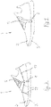
- the strap 8 is a part of the tensioning element 5 which is made of a thin sheet metal plate which is machined according to the shape as becomes apparent from figure 1 , i. e. the tensioning element 5 consists substantially of a laminar part 12.
- the tensioning element 5 is thus produced from a thin material with a thickness t which is preferably below 1.0 mm. Compared with the thickness t the width w of the different sections of the tensioning element 5 (see figure 1 ) is substantially bigger, e. g. at least 10 times of the thickness t. Accordingly, the tensioning element 5 comprises certain strip-like sections which are arranged in the surface of the shoe upper 2 (with the width w) which have a small extension perpendicular to the surface of the shoe upper 2 (with the thickness t).
- the laminar part 12 of the tensioning element 5 merges in the lateral and medial side of the shoe upper 2 in a lateral section 14 and a medial section 15.
- two strip-like lateral sections 14 and two medial sections 15 merge into the strap 8 which in turn carries the profile 10.
- a section of the laminar part 12 and the two strip-like lateral sections 14 as well as a section of the laminar part 12 and the two medial sections 15 form a triangular structure as becomes a parent from figure 1 (for the lateral sides of the shoe).
- the laminar part 12 of the tensioning element 5 has a central section 13.
- a switch 16 is arranged in the centre of the central section 13 by which the lacing and the de-lacing of the shoe can be carried out by the wearer of the shoe by a wipe movement of a finger across the surface of the switch 16.
- the tensioning element 5 has basically two strip-like sections which merge at the location of the strap 8 and which form a V-shaped design at the medial and at the lateral side of the shoe.
- figure 5 additionally a strip-like section is provided which runs around the heel section of the shoe to improve the lacing effect.
- the embodiment according to figure 6 is similar to that one of figure 4 . Additionally, some cables 17 are arranged which are connected with the tensioning element 5 and the sole 3 and which provides an additional lacing when the tensioning elements 5 is put under tension by a movement of the strap 8 by means of the central fastener 4.
- the tensioning element 5 is basically formed by only one strip-like section (one in the lateral side and one in the medial side of the shoe) which are connected with cables 17 which are guided in the instep region of the shoe as well as in the forefoot and in the heel region of the shoe.
- the tensioning element 5 consists basically of a single section which merges in the lateral and in the medial side of the shoe into the strap 8.
- the single elements of the tensioning element 5 are quite thin and designed as cables which run across the instep region of the shoe and around the heel section of the same.
- the tensioning element 5 is designed as a net-like structure made of different cables which finally are tensioned by the strap 8.
- the cables 17 (being finally a part of the tensioning element 5) can be connected with another part of the tensioning element 5 for example by soldering.
- the whole tensioning element 5 (with straps 8 but without cables 17) it is suggested to cut out the required shape of the tensioning element 5 from a thin (e. g. rectangular) metal plate by punching, laser cutting, electron beam cutting or the like. By this method also the grooves 10 can be cut out efficiently. This allows an economic production of the tensioning element 5.
- the tensioning element 5 by connecting several parts together. So, for example the straps 8 can be produced separately and then fixed to the rest of the structure of the tensioning element 5.
Description
- The invention relates to a shoe, especially to a sports shoe, with a shoe upper and a sole connected with the shoe upper, wherein the shoe comprises a central fastener for lacing the shoe at the foot of a wearer, wherein the central fastener comprises at least one tensioning element which is arranged on or in a region of the shoe upper by which a lacing force can be exerted onto the region of the shoe upper and at least one gear element driven by at least one electric motor, wherein a section of the tensioning element can be pulled against a fixed location of the shoe by means of the gear element to create a tensioning force for lacing the shoe at the foot of the wearer, wherein the section of the tensioning element is a strap which comprises a gearing or a profile, wherein the gear element comprises a worm which engages into the gearing or profile to pull the strap in a translational direction at the rotation of the worm by the electric motor.
- Such a shoe is disclosed in
US 2007/0261270 A1 , where a driven worm (jack screw) meshes with a thread in a bracket to tension a strap. A similar shoe, i. e. with an electric motor operated central fastener, is known fromDE 298 17 003 U1 . Here, a tensioning roller is electric motor operated for winding of a tensioning element being a cable so that the shoe can be laced and de-laced automatically and electrically respectively. InUS 2017/0265594 A1 a driven worm is engaged with a worm gear which in turn tensions a wire at its rotation. InUS 2016/0143396 A1 a gear arrangement is place in the sole which comprises driven spur gears to exert a tensioning force to a belt. - Detrimentally, all the pre-known central fastener (or central closure system) requires a certain space which is not always available at a shoe, especially at a sports shoe.
- Thus it is an object of the present invention to propose a shoe with a central fastener which has a very low demand with respect to the required space. Thus, it is aimed that the central closure system is very compact.
- The solution of this object according to the invention is defined by the appended
claim 1. - The gearing is preferably realized by a plurality of parallel grooves which are machined, especially punched, into the strap.
- The width is preferred at least 25 times as big as the thickness.
- The central section is preferably connected with at least one lateral section and at least one medial section, wherein the at least one lateral section and the at least one medial section run down from the central section to the sole.
- A preferred embodiment of the invention proposes that two lateral sections and two medial sections are arranged, wherein a part of the central section and the two lateral sections and a part of the central section and the two medial sections form a triangular structure on the surface of the shoe upper.
- The at least one lateral section and the at least one medial section merge preferably into each one strap. In this case it can be provided that two worms are arranged which each engage into one gearing or profile of the strap.
- The tensioning element is preferably made of a thin panel sheet made of metal. The thickness of the panel sheet is preferably less than 2.0 mm, specifically preferred less than 1.0 mm. The panel sheet is preferably made of light metal, especially of aluminium or magnesium.
- The switch is preferably a contact sensor which is sensitive to a wipe movement of a finger of the user of the shoe onto an actuation surface of the contact sensor.
- The control of the system can alternatively also be carried out by means of a mobile phone in which a respective app is loaded. In this case the user of the shoe can activate the lacing and de-lacing process by using his or her mobile phone.
- The gear element and the electric motor are preferably arranged in the sole of the shoe.
- As the section of the tensioning element is a strap which comprises a gearing or a profile, in which the worm of the gear element engages (i. e. meshes) it is possible to create a very compact design for the central fastener.
- In the drawings embodiments of the invention are shown.
- Fig. 1
- shows a perspective view of a shoe which is provided with a central fastener according to a first embodiment of the invention,
- Fig. 2
- shows an explosion view of a part of the central fastener, namely of a gear element with a worm and an electric motor and a strap with a gearing in which the worm meshes during intended use,
- Fig. 3
- shows a section through the shoe perpendicular to its longitudinal axis showing the central fastener (without electric motors),
- Fig. 4
- shows the side view of the shoe according to a second embodiment of the invention,
- Fig. 5
- shows the side view of the shoe according to a third embodiment of the invention,
- Fig. 6
- shows a perspective view of the shoe according to a fourth embodiment of the invention,
- Fig. 7
- shows a perspective view of the shoe according to a fifth embodiment of the invention,
- Fig. 8
- shows the side view of the shoe according to a sixth embodiment of the invention,
- Fig. 9
- shows the side view of the shoe according to a seventh embodiment of the invention,
- Fig. 10
- shows the side view of the shoe according to an eighth embodiment of the invention, and
- Fig. 11
- shows the side view of the shoe according to a ninth embodiment of the invention.
- In
figures 1 to 3 a first embodiment of the invention is shown. Ashoe 1 has a shoe upper 2 and a sole 3 connected with the shoe upper 2. The lacing of the shoe at the foot of a wearer is carried out by acentral fastener 4. - The central fastener 4 tensions a
tensioning element 5 so that a tensioning force can be exerted to the shoe upper 2 and thus to the foot of the wearer. - The tensioning of the
tensioning element 5 takes place by means of a gear element 6 (and more specifically by twogear elements 6 in the present embodiment). Thegear element 6 is shown infigure 2 in an explosion view. It comprises anelectric motor 7 which drives aworm 11. Asection 8 of thetensioning element 5 is designed as a strap in which a gearing orprofile 10 is machined. In the present case according tofigure 2 thegearing 10 is established by a plurality of parallel grooves which are punched into thestrap 8. - Worms 11 of the mentioned kind are well known in the art. Reference is made to common worm gears consisting of a driving worm and a driven worm wheel. Such a worm which can mesh with the grooves in the
strap 8 is suitable for the present solution. - The
electric motor 7 as well as theworm 11 are arranged at afixed location 9 of the shoe and more specifically within the sole 3. Accordingly, when theelectric motor 7 rotates theworm 11 and when theworm 11 meshes with thegearing 10 in thestrap 8, the end of thestrap 8 is moved in a translational direction T (seefigure 2 and3 ). - Fixed
location 9 means in the above context that this is a location in the shoe against which thestrap 8 is pulled at the actuation of thegear element 6. That is, while thestrap 8 can be moved in translational direction T relatively to the shoe and specifically in the sole 3, theworm 11 together with theelectric motor 7 is arranged stationary in theshoe 1 and specifically in the sole 3. - The
strap 8 is a part of thetensioning element 5 which is made of a thin sheet metal plate which is machined according to the shape as becomes apparent fromfigure 1 , i. e. thetensioning element 5 consists substantially of alaminar part 12. - The
tensioning element 5 is thus produced from a thin material with a thickness t which is preferably below 1.0 mm. Compared with the thickness t the width w of the different sections of the tensioning element 5 (seefigure 1 ) is substantially bigger, e. g. at least 10 times of the thickness t. Accordingly, thetensioning element 5 comprises certain strip-like sections which are arranged in the surface of the shoe upper 2 (with the width w) which have a small extension perpendicular to the surface of the shoe upper 2 (with the thickness t). - As can be seen specifically from
figure 3 thelaminar part 12 of thetensioning element 5 merges in the lateral and medial side of the shoe upper 2 in alateral section 14 and amedial section 15. In the case of the depicted embodiment two strip-likelateral sections 14 and twomedial sections 15 merge into thestrap 8 which in turn carries theprofile 10. - Preferably a section of the
laminar part 12 and the two strip-likelateral sections 14 as well as a section of thelaminar part 12 and the twomedial sections 15 form a triangular structure as becomes a parent fromfigure 1 (for the lateral sides of the shoe). - In
figure 3 it can be seen that twogear element 6 are arranged in the sole 3 of theshoe 1, wherein eachgear element 6 cooperates with astrap 8 of thetensioning element 5. It should be noted that infigure 3 the twogear elements 6 are offset in a direction perpendicular to the drawing plane offigure 3 . When the two electric motors 7 (not shown infigure 3 ) are operated simultaneously the twostraps 8 are moved toward another or away from another (depending on the rotation direction of the electric motors 7) to lace or to de-lace theshoe 1. - As can be seen from
figure 1 thelaminar part 12 of thetensioning element 5 has a central section 13. A switch 16 is arranged in the centre of the central section 13 by which the lacing and the de-lacing of the shoe can be carried out by the wearer of the shoe by a wipe movement of a finger across the surface of the switch 16. - Thus, when the two electric motors 7 (not shown) of the two
gear elements 6 infigure 3 are activated the twostraps 8 are pulled by the twoworms 11 in the translational direction T and thus the shoe is laced at the foot of the wearer. - Coming now to
figures 4 to 11 different alternative embodiments of the present invention and more specifically of thetensioning element 5 are shown. As a common feature the design of the central fastener is always as described in connection withfigures 1 to 3 . Thus, the different embodiments offigures 4 to 11 concern the design of thetensioning element 5 only. - In
figure 4 thetensioning element 5 has basically two strip-like sections which merge at the location of thestrap 8 and which form a V-shaped design at the medial and at the lateral side of the shoe. - In
figure 5 additionally a strip-like section is provided which runs around the heel section of the shoe to improve the lacing effect. - The embodiment according to
figure 6 is similar to that one offigure 4 . Additionally, somecables 17 are arranged which are connected with thetensioning element 5 and the sole 3 and which provides an additional lacing when thetensioning elements 5 is put under tension by a movement of thestrap 8 by means of thecentral fastener 4. - In
figure 7 additional strip-like part of thetensioning element 5 are provided in the forefoot and the rearfoot region. Also herecables 17 are provided which span over the instep region of the shoe. - In
figure 8 thetensioning element 5 is basically formed by only one strip-like section (one in the lateral side and one in the medial side of the shoe) which are connected withcables 17 which are guided in the instep region of the shoe as well as in the forefoot and in the heel region of the shoe. - In
figure 9 thetensioning element 5 consists basically of a single section which merges in the lateral and in the medial side of the shoe into thestrap 8. - In
figure 10 the single elements of thetensioning element 5 are quite thin and designed as cables which run across the instep region of the shoe and around the heel section of the same. - Finally, in
figure 11 thetensioning element 5 is designed as a net-like structure made of different cables which finally are tensioned by thestrap 8. - The cables 17 (being finally a part of the tensioning element 5) can be connected with another part of the
tensioning element 5 for example by soldering. - As a preferred manufacturing method of the whole tensioning element 5 (with
straps 8 but without cables 17) it is suggested to cut out the required shape of thetensioning element 5 from a thin (e. g. rectangular) metal plate by punching, laser cutting, electron beam cutting or the like. By this method also thegrooves 10 can be cut out efficiently. This allows an economic production of thetensioning element 5. - It is also possible to produce the
tensioning element 5 by connecting several parts together. So, for example thestraps 8 can be produced separately and then fixed to the rest of the structure of thetensioning element 5. - Not shown in the figures are a battery and wires which are of course necessary for the operation of the
electric motors 7. -
- 1
- Shoe
- 2
- Shoe upper
- 3
- Sole
- 4
- Central fastener
- 5
- Tensioning element
- 6
- Gear element
- 7
- Electric motor
- 8
- Section of the tensioning element (strap)
- 9
- Fixed location of the shoe
- 10
- Gearing / profile
- 11
- Worm
- 12
- Laminar part of the tensioning element
- 13
- Central section
- 14
- Lateral section
- 15
- Medial section
- 16
- Switch
- 17
- Cable
- T
- Translational direction
- t
- Thickness
- w
- Width
Claims (12)
- Shoe (1), especially sports shoe, with a shoe upper (2) and a sole (3) connected with the shoe upper (2), wherein the shoe (1) comprises a central fastener (4) for lacing the shoe (1) at the foot of a wearer, wherein the central fastener (4) comprises- at least one tensioning element (5) which is arranged on or in a region of the shoe upper (2) by which a lacing force can be exerted onto the region of the shoe upper (2) and- at least one gear element (6) driven by at least one electric motor (7), wherein a section (8) of the tensioning element (5) can be pulled against a fixed location (9) of the shoe (1) by means of the gear element (6) to create a tensioning force for lacing the shoe (1) at the foot of the wearer,wherein the section (8) of the tensioning element (5) is a strap which comprises a gearing (10) or a profile, wherein the gear element (6) comprises a worm (11) which engages into the gearing (10) or profile to pull the strap (8) in a translational direction (T) at the rotation of the worm (11) by the electric motor (7),
characterized in thatthe tensioning element (5) comprises at least one laminar part (12) which is arranged in the plane of the surface of the shoe upper (2), wherein the laminar part (12) has a thickness (t) measured perpendicular to the surface of the shoe upper (2) and a width (w) measured in the plane of the surface of the shoe upper (2), wherein the width (w) is at least 10 times as big as the thickness (t),wherein the laminar part (12) comprises a central section (13) which is arranged in the instep region of the shoe (1),wherein a switch (16) for controlling the central fastener (4) is arranged in the central section (13) and wherein the switch (16) is made of unitary design with the tensioning element (5). - Shoe according to claim 1, characterized in that the gearing (10) is realized by a plurality of parallel grooves which are machined, especially punched, into the strap (8).
- Shoe according to claim 1 or 2, characterized in that the width (w) is at least 25 times as big as the thickness (t).
- Shoe according to one of claims 1 to 3, characterized in that the central section (13) is connected with at least one lateral section (14) and at least one medial section (15), wherein the at least one lateral section (14) and the at least one medial section (15) run down from the central section (13) to the sole (3).
- Shoe according to claim 4, characterized in that two lateral sections (14) and two medial sections (15) are arranged, wherein a part of the central section (13) and the two lateral sections (14) and a part of the central section (13) and the two medial sections (15) form a triangular structure.
- Shoe according to claim 4 or 5, characterized in that the at least one lateral section (14) and the at least one medial section (15) merge into each one strap (8).
- Shoe according to claim 6, characterized in that two worms (11) are arranged which each engage into one gearing (10) or profile of the strap (8).
- Shoe according to one of claims 1 to 7, characterized in that the tensioning element (5) is made of a thin panel sheet made of metal.
- Shoe according to claim 8, characterized in that the thickness (t) of the panel sheet is less than 2.0 mm, preferably less than 1.0 mm.
- Shoe according to claim 8 or 9, characterized in that the panel sheet is made of light metal, especially of aluminium or magnesium.
- Shoe according to one of claims 1 to 10, characterized in that the switch (16) is a contact sensor which is sensitive to a wipe movement of a finger of the user of the shoe (1) onto an actuation surface of the contact sensor.
- Shoe according to one of claims 1 to 11, characterized in that the gear element (6) and the electric motor (7) are arranged in the sole (3) of the shoe (1).
Applications Claiming Priority (1)
| Application Number | Priority Date | Filing Date | Title |
|---|---|---|---|
| PCT/EP2018/065754 WO2019238231A1 (en) | 2018-06-14 | 2018-06-14 | Shoe, especially a sports shoe |
Publications (2)
| Publication Number | Publication Date |
|---|---|
| EP3806688A1 EP3806688A1 (en) | 2021-04-21 |
| EP3806688B1 true EP3806688B1 (en) | 2022-09-14 |
Family
ID=62683203
Family Applications (1)
| Application Number | Title | Priority Date | Filing Date |
|---|---|---|---|
| EP18732311.8A Active EP3806688B1 (en) | 2018-06-14 | 2018-06-14 | Shoe, especially a sports shoe |
Country Status (5)
| Country | Link |
|---|---|
| US (1) | US11793275B2 (en) |
| EP (1) | EP3806688B1 (en) |
| JP (1) | JP7108054B2 (en) |
| CN (1) | CN112292051B (en) |
| WO (1) | WO2019238231A1 (en) |
Families Citing this family (1)
| Publication number | Priority date | Publication date | Assignee | Title |
|---|---|---|---|---|
| DE112021001572T5 (en) * | 2020-03-12 | 2023-01-12 | Roger Neil Jr. Rovekamp | PORTABLE AUTO TENSIONING DEVICE |
Citations (1)
| Publication number | Priority date | Publication date | Assignee | Title |
|---|---|---|---|---|
| CA2911999A1 (en) * | 2015-11-16 | 2017-05-16 | James Shand | Skate fastener |
Family Cites Families (28)
| Publication number | Priority date | Publication date | Assignee | Title |
|---|---|---|---|---|
| US4300256A (en) * | 1979-08-31 | 1981-11-17 | R. G. Barry Corporation | Clog-type shoes and method for their production |
| FR2582486B1 (en) * | 1985-05-31 | 1987-08-21 | Salomon Sa | DEVICE FOR TURNING ON A FLEXIBLE MEMBER ENSURING THE LINK BETWEEN TWO PARTS, APPLICABLE IN PARTICULAR TO THE CLOSING AND TIGHTENING OF A SKI SHOE ON THE FOOT OF A SKIER |
| US5205055A (en) * | 1992-02-03 | 1993-04-27 | Harrell Aaron D | Pneumatic shoe lacing apparatus |
| DE19833801A1 (en) * | 1998-07-28 | 2000-02-03 | Erich Brosig | Method for automatically lacing and unlacing a shoe has an electric motor operated by the foot operating a lacing system and a spring to open the shoe when the foot is removed |
| DE29817003U1 (en) | 1998-09-22 | 1999-03-25 | Merlaku Kastriot | High-tech shoe closure system |
| US6993858B2 (en) * | 2003-05-23 | 2006-02-07 | Crocs, Inc. | Breathable footwear pieces |
| FR2872389A1 (en) * | 2004-07-02 | 2006-01-06 | Salomon Sa | FOOTWEAR ARTICLE AND LACE SYSTEM FOR SUCH A ARTICLE |
| US7503131B2 (en) * | 2006-05-15 | 2009-03-17 | Adam Ian Nadel | Ski boot tightening system |
| US9907359B2 (en) * | 2008-05-02 | 2018-03-06 | Nike, Inc. | Lacing system with guide elements |
| US8046937B2 (en) * | 2008-05-02 | 2011-11-01 | Nike, Inc. | Automatic lacing system |
| US8939224B2 (en) * | 2012-11-15 | 2015-01-27 | Charles Spencer Potter | Hoof medical device and method |
| WO2015006616A1 (en) | 2013-07-10 | 2015-01-15 | Boa Technology Inc. | Closure devices including incremental release mechanisms and methods therefor |
| US9629418B2 (en) | 2014-04-15 | 2017-04-25 | Nike, Inc. | Footwear having motorized adjustment system and elastic upper |
| CN104585975A (en) * | 2014-05-22 | 2015-05-06 | 郑君 | A device which automatically tighten or loosen a tie |
| CA2956846C (en) * | 2014-07-31 | 2019-05-28 | Powerlace Technologies Inc. | Closure system |
| US9848674B2 (en) * | 2015-04-14 | 2017-12-26 | Nike, Inc. | Article of footwear with weight-activated cinching apparatus |
| CN107847015B (en) * | 2015-05-29 | 2021-04-13 | 耐克创新有限合伙公司 | Motorized tensioning device with compact spool system |
| CN107847016B (en) * | 2015-05-29 | 2020-11-27 | 耐克创新有限合伙公司 | Article of footwear incorporating a motorized tensioning device with split spool system |
| EP3358981B1 (en) * | 2015-10-07 | 2019-07-17 | Puma Se | Shoe, in particular athletic shoe |
| EP3383211B1 (en) * | 2015-12-02 | 2019-09-25 | Puma Se | Method for lacing a shoe, particularly a sports shoe |
| US10660406B2 (en) * | 2016-03-15 | 2020-05-26 | Nike, Inc. | Tensioning system and reel member for footwear |
| JP6896758B2 (en) | 2016-03-15 | 2021-06-30 | ナイキ イノベイト シーブイ | Capacitive foot presence sensing for footwear |
| US10390589B2 (en) * | 2016-03-15 | 2019-08-27 | Nike, Inc. | Drive mechanism for automated footwear platform |
| WO2017160966A1 (en) * | 2016-03-15 | 2017-09-21 | Mizuno Usa, Inc. | Footwear having an adjustable heel mechanism |
| WO2017185160A1 (en) | 2016-04-25 | 2017-11-02 | Nocturis Inc. | Shoe lacing system |
| EP4218479A1 (en) * | 2016-11-18 | 2023-08-02 | Nike Innovate C.V. | Compact motorized tensioning device for footwear |
| CA3042721C (en) * | 2016-11-22 | 2023-09-26 | Puma SE | Method for fastening a shoe, in particular a sports shoe, and shoe, in particular sports shoe |
| US10849388B2 (en) * | 2017-04-27 | 2020-12-01 | Cincinnati Automation & Mechatronics, LLC | Automatic retention apparatus |
-
2018
- 2018-06-14 US US17/251,099 patent/US11793275B2/en active Active
- 2018-06-14 CN CN201880094501.7A patent/CN112292051B/en active Active
- 2018-06-14 WO PCT/EP2018/065754 patent/WO2019238231A1/en active Application Filing
- 2018-06-14 EP EP18732311.8A patent/EP3806688B1/en active Active
- 2018-06-14 JP JP2020569732A patent/JP7108054B2/en active Active
Patent Citations (1)
| Publication number | Priority date | Publication date | Assignee | Title |
|---|---|---|---|---|
| CA2911999A1 (en) * | 2015-11-16 | 2017-05-16 | James Shand | Skate fastener |
Also Published As
| Publication number | Publication date |
|---|---|
| US11793275B2 (en) | 2023-10-24 |
| JP2021527485A (en) | 2021-10-14 |
| CN112292051B (en) | 2022-07-19 |
| CN112292051A (en) | 2021-01-29 |
| EP3806688A1 (en) | 2021-04-21 |
| JP7108054B2 (en) | 2022-07-27 |
| US20210177099A1 (en) | 2021-06-17 |
| WO2019238231A1 (en) | 2019-12-19 |
Similar Documents
| Publication | Publication Date | Title |
|---|---|---|
| US11589635B2 (en) | Article with tensioning system including tension balancing member | |
| US11825913B2 (en) | Position sensing assembly for a tensioning system | |
| EP3302155B1 (en) | Motorized tensioning device with compact spool system | |
| EP3806688B1 (en) | Shoe, especially a sports shoe | |
| JP6882472B2 (en) | How to tighten shoes, especially athletic shoes, and shoes, especially athletic shoes | |
| KR102545514B1 (en) | Transmission for motorized tensioning system for footwear | |
| US10758011B2 (en) | Method for lacing a shoe, particularly a sports shoe | |
| US9907361B2 (en) | Article of footwear with channels in sole structure | |
| US9872539B2 (en) | Article with tensioning system including driven tensioning members | |
| EP3302125B1 (en) | A control device for an article of footwear | |
| US10645990B2 (en) | Article of footwear with adjustable sole | |
| US10342293B2 (en) | Method of forming an aperture in a reel member of a tensioning system for an article of footwear | |
| JP2018504963A (en) | Shoes, especially athletic shoes | |
| RU2015131808A (en) | REINFORCED LINING MACHINE | |
| CN111836562B (en) | Shoes with automatic lacing | |
| FR2663346A1 (en) | SAWING CUTTER CYLINDER HAVING A HELICOUIDALE TRIM IN SAW TOOTH AND THREAD OF TRIM FOR CARRYING OUT SAID. | |
| KR20170142828A (en) | Spike shoes | |
| CN105193008B (en) | A kind of shoemaking piece side machine for installing protector additional | |
| JP3126793U (en) | Shoes with heel band | |
| ITMI20120805A1 (en) | MACHINE FOR ASSEMBLING AND REBATING THE TIP OF A FOOTWEAR | |
| JPH06275362A (en) | Terminal arranging device for covered electric wire and terminal treatment device | |
| JP2008268667A (en) | Electronic display device and manufacturing method thereof | |
| BR102012021148A2 (en) | Yarn Stripping Machine |
Legal Events
| Date | Code | Title | Description |
|---|---|---|---|
| STAA | Information on the status of an ep patent application or granted ep patent |
Free format text: STATUS: UNKNOWN |
|
| STAA | Information on the status of an ep patent application or granted ep patent |
Free format text: STATUS: THE INTERNATIONAL PUBLICATION HAS BEEN MADE |
|
| STAA | Information on the status of an ep patent application or granted ep patent |
Free format text: STATUS: THE INTERNATIONAL PUBLICATION HAS BEEN MADE |
|
| PUAI | Public reference made under article 153(3) epc to a published international application that has entered the european phase |
Free format text: ORIGINAL CODE: 0009012 |
|
| STAA | Information on the status of an ep patent application or granted ep patent |
Free format text: STATUS: REQUEST FOR EXAMINATION WAS MADE |
|
| 17P | Request for examination filed |
Effective date: 20210114 |
|
| AK | Designated contracting states |
Kind code of ref document: A1 Designated state(s): AL AT BE BG CH CY CZ DE DK EE ES FI FR GB GR HR HU IE IS IT LI LT LU LV MC MK MT NL NO PL PT RO RS SE SI SK SM TR |
|
| AX | Request for extension of the european patent |
Extension state: BA ME |
|
| DAV | Request for validation of the european patent (deleted) | ||
| DAX | Request for extension of the european patent (deleted) | ||
| REG | Reference to a national code |
Ref country code: DE Ref legal event code: R079 Ref document number: 602018040649 Country of ref document: DE Free format text: PREVIOUS MAIN CLASS: A43B0003000000 Ipc: A43B0003340000 |
|
| GRAP | Despatch of communication of intention to grant a patent |
Free format text: ORIGINAL CODE: EPIDOSNIGR1 |
|
| STAA | Information on the status of an ep patent application or granted ep patent |
Free format text: STATUS: GRANT OF PATENT IS INTENDED |
|
| RIC1 | Information provided on ipc code assigned before grant |
Ipc: A43C 11/16 20060101ALI20220429BHEP Ipc: A43B 3/34 20220101AFI20220429BHEP |
|
| INTG | Intention to grant announced |
Effective date: 20220607 |
|
| GRAS | Grant fee paid |
Free format text: ORIGINAL CODE: EPIDOSNIGR3 |
|
| GRAA | (expected) grant |
Free format text: ORIGINAL CODE: 0009210 |
|
| STAA | Information on the status of an ep patent application or granted ep patent |
Free format text: STATUS: THE PATENT HAS BEEN GRANTED |
|
| AK | Designated contracting states |
Kind code of ref document: B1 Designated state(s): AL AT BE BG CH CY CZ DE DK EE ES FI FR GB GR HR HU IE IS IT LI LT LU LV MC MK MT NL NO PL PT RO RS SE SI SK SM TR |
|
| REG | Reference to a national code |
Ref country code: GB Ref legal event code: FG4D |
|
| REG | Reference to a national code |
Ref country code: CH Ref legal event code: EP |
|
| REG | Reference to a national code |
Ref country code: DE Ref legal event code: R096 Ref document number: 602018040649 Country of ref document: DE |
|
| REG | Reference to a national code |
Ref country code: IE Ref legal event code: FG4D |
|
| REG | Reference to a national code |
Ref country code: AT Ref legal event code: REF Ref document number: 1518174 Country of ref document: AT Kind code of ref document: T Effective date: 20221015 |
|
| REG | Reference to a national code |
Ref country code: LT Ref legal event code: MG9D |
|
| REG | Reference to a national code |
Ref country code: NL Ref legal event code: MP Effective date: 20220914 |
|
| PG25 | Lapsed in a contracting state [announced via postgrant information from national office to epo] |
Ref country code: SE Free format text: LAPSE BECAUSE OF FAILURE TO SUBMIT A TRANSLATION OF THE DESCRIPTION OR TO PAY THE FEE WITHIN THE PRESCRIBED TIME-LIMIT Effective date: 20220914 Ref country code: RS Free format text: LAPSE BECAUSE OF FAILURE TO SUBMIT A TRANSLATION OF THE DESCRIPTION OR TO PAY THE FEE WITHIN THE PRESCRIBED TIME-LIMIT Effective date: 20220914 Ref country code: NO Free format text: LAPSE BECAUSE OF FAILURE TO SUBMIT A TRANSLATION OF THE DESCRIPTION OR TO PAY THE FEE WITHIN THE PRESCRIBED TIME-LIMIT Effective date: 20221214 Ref country code: LV Free format text: LAPSE BECAUSE OF FAILURE TO SUBMIT A TRANSLATION OF THE DESCRIPTION OR TO PAY THE FEE WITHIN THE PRESCRIBED TIME-LIMIT Effective date: 20220914 Ref country code: LT Free format text: LAPSE BECAUSE OF FAILURE TO SUBMIT A TRANSLATION OF THE DESCRIPTION OR TO PAY THE FEE WITHIN THE PRESCRIBED TIME-LIMIT Effective date: 20220914 Ref country code: FI Free format text: LAPSE BECAUSE OF FAILURE TO SUBMIT A TRANSLATION OF THE DESCRIPTION OR TO PAY THE FEE WITHIN THE PRESCRIBED TIME-LIMIT Effective date: 20220914 |
|
| REG | Reference to a national code |
Ref country code: AT Ref legal event code: MK05 Ref document number: 1518174 Country of ref document: AT Kind code of ref document: T Effective date: 20220914 |
|
| PG25 | Lapsed in a contracting state [announced via postgrant information from national office to epo] |
Ref country code: HR Free format text: LAPSE BECAUSE OF FAILURE TO SUBMIT A TRANSLATION OF THE DESCRIPTION OR TO PAY THE FEE WITHIN THE PRESCRIBED TIME-LIMIT Effective date: 20220914 Ref country code: GR Free format text: LAPSE BECAUSE OF FAILURE TO SUBMIT A TRANSLATION OF THE DESCRIPTION OR TO PAY THE FEE WITHIN THE PRESCRIBED TIME-LIMIT Effective date: 20221215 |
|
| PG25 | Lapsed in a contracting state [announced via postgrant information from national office to epo] |
Ref country code: SM Free format text: LAPSE BECAUSE OF FAILURE TO SUBMIT A TRANSLATION OF THE DESCRIPTION OR TO PAY THE FEE WITHIN THE PRESCRIBED TIME-LIMIT Effective date: 20220914 Ref country code: RO Free format text: LAPSE BECAUSE OF FAILURE TO SUBMIT A TRANSLATION OF THE DESCRIPTION OR TO PAY THE FEE WITHIN THE PRESCRIBED TIME-LIMIT Effective date: 20220914 Ref country code: PT Free format text: LAPSE BECAUSE OF FAILURE TO SUBMIT A TRANSLATION OF THE DESCRIPTION OR TO PAY THE FEE WITHIN THE PRESCRIBED TIME-LIMIT Effective date: 20230116 Ref country code: ES Free format text: LAPSE BECAUSE OF FAILURE TO SUBMIT A TRANSLATION OF THE DESCRIPTION OR TO PAY THE FEE WITHIN THE PRESCRIBED TIME-LIMIT Effective date: 20220914 Ref country code: CZ Free format text: LAPSE BECAUSE OF FAILURE TO SUBMIT A TRANSLATION OF THE DESCRIPTION OR TO PAY THE FEE WITHIN THE PRESCRIBED TIME-LIMIT Effective date: 20220914 Ref country code: AT Free format text: LAPSE BECAUSE OF FAILURE TO SUBMIT A TRANSLATION OF THE DESCRIPTION OR TO PAY THE FEE WITHIN THE PRESCRIBED TIME-LIMIT Effective date: 20220914 |
|
| PG25 | Lapsed in a contracting state [announced via postgrant information from national office to epo] |
Ref country code: SK Free format text: LAPSE BECAUSE OF FAILURE TO SUBMIT A TRANSLATION OF THE DESCRIPTION OR TO PAY THE FEE WITHIN THE PRESCRIBED TIME-LIMIT Effective date: 20220914 Ref country code: PL Free format text: LAPSE BECAUSE OF FAILURE TO SUBMIT A TRANSLATION OF THE DESCRIPTION OR TO PAY THE FEE WITHIN THE PRESCRIBED TIME-LIMIT Effective date: 20220914 Ref country code: IS Free format text: LAPSE BECAUSE OF FAILURE TO SUBMIT A TRANSLATION OF THE DESCRIPTION OR TO PAY THE FEE WITHIN THE PRESCRIBED TIME-LIMIT Effective date: 20230114 Ref country code: EE Free format text: LAPSE BECAUSE OF FAILURE TO SUBMIT A TRANSLATION OF THE DESCRIPTION OR TO PAY THE FEE WITHIN THE PRESCRIBED TIME-LIMIT Effective date: 20220914 |
|
| REG | Reference to a national code |
Ref country code: DE Ref legal event code: R097 Ref document number: 602018040649 Country of ref document: DE |
|
| PG25 | Lapsed in a contracting state [announced via postgrant information from national office to epo] |
Ref country code: NL Free format text: LAPSE BECAUSE OF FAILURE TO SUBMIT A TRANSLATION OF THE DESCRIPTION OR TO PAY THE FEE WITHIN THE PRESCRIBED TIME-LIMIT Effective date: 20220914 Ref country code: AL Free format text: LAPSE BECAUSE OF FAILURE TO SUBMIT A TRANSLATION OF THE DESCRIPTION OR TO PAY THE FEE WITHIN THE PRESCRIBED TIME-LIMIT Effective date: 20220914 |
|
| PLBE | No opposition filed within time limit |
Free format text: ORIGINAL CODE: 0009261 |
|
| STAA | Information on the status of an ep patent application or granted ep patent |
Free format text: STATUS: NO OPPOSITION FILED WITHIN TIME LIMIT |
|
| PG25 | Lapsed in a contracting state [announced via postgrant information from national office to epo] |
Ref country code: DK Free format text: LAPSE BECAUSE OF FAILURE TO SUBMIT A TRANSLATION OF THE DESCRIPTION OR TO PAY THE FEE WITHIN THE PRESCRIBED TIME-LIMIT Effective date: 20220914 |
|
| PGFP | Annual fee paid to national office [announced via postgrant information from national office to epo] |
Ref country code: FR Payment date: 20230622 Year of fee payment: 6 Ref country code: DE Payment date: 20230620 Year of fee payment: 6 |
|
| 26N | No opposition filed |
Effective date: 20230615 |
|
| PG25 | Lapsed in a contracting state [announced via postgrant information from national office to epo] |
Ref country code: SI Free format text: LAPSE BECAUSE OF FAILURE TO SUBMIT A TRANSLATION OF THE DESCRIPTION OR TO PAY THE FEE WITHIN THE PRESCRIBED TIME-LIMIT Effective date: 20220914 |
|
| PGFP | Annual fee paid to national office [announced via postgrant information from national office to epo] |
Ref country code: IT Payment date: 20230630 Year of fee payment: 6 Ref country code: GB Payment date: 20230622 Year of fee payment: 6 |
|
| PG25 | Lapsed in a contracting state [announced via postgrant information from national office to epo] |
Ref country code: MC Free format text: LAPSE BECAUSE OF FAILURE TO SUBMIT A TRANSLATION OF THE DESCRIPTION OR TO PAY THE FEE WITHIN THE PRESCRIBED TIME-LIMIT Effective date: 20220914 |
|
| PG25 | Lapsed in a contracting state [announced via postgrant information from national office to epo] |
Ref country code: MC Free format text: LAPSE BECAUSE OF FAILURE TO SUBMIT A TRANSLATION OF THE DESCRIPTION OR TO PAY THE FEE WITHIN THE PRESCRIBED TIME-LIMIT Effective date: 20220914 |
|
| REG | Reference to a national code |
Ref country code: CH Ref legal event code: PL |
|
| REG | Reference to a national code |
Ref country code: BE Ref legal event code: MM Effective date: 20230630 |
|
| PG25 | Lapsed in a contracting state [announced via postgrant information from national office to epo] |
Ref country code: LU Free format text: LAPSE BECAUSE OF NON-PAYMENT OF DUE FEES Effective date: 20230614 |
|
| REG | Reference to a national code |
Ref country code: IE Ref legal event code: MM4A |
|
| PG25 | Lapsed in a contracting state [announced via postgrant information from national office to epo] |
Ref country code: LU Free format text: LAPSE BECAUSE OF NON-PAYMENT OF DUE FEES Effective date: 20230614 |