EP3806297A1 - Method and device for twisting a winding head of a stator, and stator for an electrical machine - Google Patents
Method and device for twisting a winding head of a stator, and stator for an electrical machine Download PDFInfo
- Publication number
- EP3806297A1 EP3806297A1 EP19472002.5A EP19472002A EP3806297A1 EP 3806297 A1 EP3806297 A1 EP 3806297A1 EP 19472002 A EP19472002 A EP 19472002A EP 3806297 A1 EP3806297 A1 EP 3806297A1
- Authority
- EP
- European Patent Office
- Prior art keywords
- conductor
- stator core
- end section
- face
- radial direction
- Prior art date
- Legal status (The legal status is an assumption and is not a legal conclusion. Google has not performed a legal analysis and makes no representation as to the accuracy of the status listed.)
- Granted
Links
Images


Classifications
-
- H—ELECTRICITY
- H02—GENERATION; CONVERSION OR DISTRIBUTION OF ELECTRIC POWER
- H02K—DYNAMO-ELECTRIC MACHINES
- H02K15/00—Processes or apparatus specially adapted for manufacturing, assembling, maintaining or repairing of dynamo-electric machines
- H02K15/30—Manufacture of winding connections
- H02K15/33—Connecting winding sections; Forming leads; Connecting leads to terminals
- H02K15/35—Form-wound windings
- H02K15/36—Processes or apparatus for simultaneously twisting two or more open ends of hairpins after their insertion into the machine
-
- H—ELECTRICITY
- H02—GENERATION; CONVERSION OR DISTRIBUTION OF ELECTRIC POWER
- H02K—DYNAMO-ELECTRIC MACHINES
- H02K15/00—Processes or apparatus specially adapted for manufacturing, assembling, maintaining or repairing of dynamo-electric machines
- H02K15/02—Processes or apparatus specially adapted for manufacturing, assembling, maintaining or repairing of dynamo-electric machines of stator or rotor bodies
- H02K15/021—Magnetic cores
- H02K15/026—Wound cores
-
- H—ELECTRICITY
- H02—GENERATION; CONVERSION OR DISTRIBUTION OF ELECTRIC POWER
- H02K—DYNAMO-ELECTRIC MACHINES
- H02K15/00—Processes or apparatus specially adapted for manufacturing, assembling, maintaining or repairing of dynamo-electric machines
- H02K15/04—Processes or apparatus specially adapted for manufacturing, assembling, maintaining or repairing of dynamo-electric machines of windings prior to their mounting into the machines
- H02K15/0414—Processes or apparatus specially adapted for manufacturing, assembling, maintaining or repairing of dynamo-electric machines of windings prior to their mounting into the machines the windings consisting of separate elements, e.g. bars, segments or half coils
- H02K15/0421—Processes or apparatus specially adapted for manufacturing, assembling, maintaining or repairing of dynamo-electric machines of windings prior to their mounting into the machines the windings consisting of separate elements, e.g. bars, segments or half coils and consisting of single conductors, e.g. hairpins
- H02K15/0428—Processes or apparatus for simultaneously twisting two or more hairpins
-
- H—ELECTRICITY
- H02—GENERATION; CONVERSION OR DISTRIBUTION OF ELECTRIC POWER
- H02K—DYNAMO-ELECTRIC MACHINES
- H02K15/00—Processes or apparatus specially adapted for manufacturing, assembling, maintaining or repairing of dynamo-electric machines
- H02K15/20—Shaping or compacting conductors or winding heads after the installation of the winding in the cores or machines; Applying fastening means on winding heads
- H02K15/24—Shaping or compacting winding heads
-
- H—ELECTRICITY
- H02—GENERATION; CONVERSION OR DISTRIBUTION OF ELECTRIC POWER
- H02K—DYNAMO-ELECTRIC MACHINES
- H02K15/00—Processes or apparatus specially adapted for manufacturing, assembling, maintaining or repairing of dynamo-electric machines
- H02K15/06—Embedding prefabricated windings in the machines
- H02K15/062—Windings in slots; Salient pole windings
- H02K15/064—Windings consisting of separate segments
Definitions
- the invention relates to a method for twisting a winding head of a stator, wherein during a twisting process of an end section of conductors of the winding resp. stator, protruding over an end face of a stator core, a distance of the conductors to each other in radial direction of the stator core is at least partially enlarged. Furthermore, the invention relates to a device for twisting a winding head of a stator. A further part of the invention is a stator for an electrical machine.
- the stator comprises a stator core and a plurality of conductors, which are arranged in slots of the stator core.
- the stator core usually comprises a plurality of lamination stacks, which are stacked together forming the stator core.
- the slots are arranged on an inner surface of the stator core, extending between a first end face of the stator and a second end face of the stator being spaced to the first end face. Furthermore, the slots are arranged in peripheral direction of the stator spaced to each other.
- a first row of conductors and a second row of conductors are arranged in the slots, wherein the first conductors and the second conductors are arranged in radial direction of the stator core next to each other.
- the conductors of the first row and the second row protrude over the first end face of the stator core.
- These conductor ends are twisted in peripheral direction of the stator core wherein the first conductor ends are twisted clockwise, and the second conductor ends are twisted counterclockwise.
- a coating of the conductors is stressed by friction and might crack.
- an isolation paper is placed between the first row and the second row of the conductors.
- the arrangement of an isolation paper is sometimes difficult and time consuming.
- EP 1 376 818 A2 describes a method for twisting a winding head of a stator having a radial gap between the conductors.
- a tail side coil end includes a plurality of tail conductor pairs sequentially disposed with predetermined radial gaps.
- the radial gaps between the conductor pairs are widened near the end surface of a stator core.
- This arrangement prevents adjacent tail joint portions or adjacent slanting portions from undesirably contacting with each other, thereby adequately maintaining electric insulation between the tail conductor pairs and improving the space factor of the slot.
- the document does not describe how the radial gaps between the conductor pairs are widened and how this gap can be reliably shaped during and/or after the twisting process of the conductor pairs.
- a method for twisting a winding head of a stator comprising the following steps:
- a hollow cylindrical stator core is provided.
- the stator core comprises a plurality of lamination stacks, arranged next to each other, forming the stator core.
- the stator core comprises a first end face and a second end face, wherein the first end face is spaced apart to the second end face in longitudinal direction of the stator core.
- the longitudinal direction of the stator core corresponds to the longitudinal axis of the cylindrical stator core.
- At least a slot is arranged on an inner surface of the stator core facing the longitudinal axis of the stator core, wherein the slot extends between the first end face and the second end face having a slot depth in radial direction of the stator core.
- the stator core comprises a plurality of slots on the inner surface, wherein the slots are spaced to each other in peripheral direction of the stator core.
- At least a first conductor and a second conductor are arranged in the slot in radial direction of the stator core next to each other.
- the first conductor is arranged on an imaginary first circle having its circle center on the longitudinal axis of the stator core.
- the second conductor is arranged on an imaginary second circle, having a diameter smaller than the first circle, and having its circle center on the longitudinal axis of the stator core.
- At least an end section of the first conductor and an end section of the second conductor protrude and/or extend over the first end face of the stator core.
- a plurality of first conductors and a plurality of second conductors are provided.
- the plurality of first conductors is arranged in peripheral direction of the stator core on the first imaginary circle, wherein the plurality of first conductors defines a first conductor row.
- the plurality of first conductors might be arranged next to each other and/or spaced apart to each other in peripheral direction of the stator core.
- the plurality of the first conductors can be arranged in such a way that only one conductor of the first conductors is arranged in the slot of the stator core. However, it is also possible that more than one first conductor is arranged in the slot of the stator core in peripheral direction of the stator core.
- the plurality of second conductors is arranged in peripheral direction on the first imaginary circle, wherein the plurality of second conductors defines a second conductor row. More preferably, the plurality of second conductors is arranged next to each other and/or spaced apart to each other in peripheral direction of the stator core.
- the plurality of the second conductors can be arranged in such a way that only one conductor of the second conductors is arranged in the slot of the stator core. However, it is also possible that more than one second conductor is arranged in the slot of the stator core in peripheral direction of the stator core.
- a winding core is arranged on the stator, the stator core and/or the first end face of the stator core.
- the winding core is arranged on the stator core resp. the end face in longitudinal direction of the stator core.
- the winding core might have a cylindrical or a hollow cylindrical structure and/or shape.
- the winding core comprises at least one cam.
- the cam protrudes in radial direction outwardly.
- the winding core comprises a plurality of cams wherein the cams are spaced to each other in peripheral direction of the winding core.
- the winding core can also be named as a necking tool.
- the end section of the first conductor After arranging the winding core on the stator, resp. the end face of the stator core, the end section of the first conductor is twisted in peripheral direction of the stator core. Due to that twisting process, the end section of the first conductor is moved over the cam, wherein a part of the end section of the first conductor, between the first end face of the stator core and a distal end of the end section of the first conductor facing away from the first end face, is bend and/or necked in radial direction of the stator core in such a way, that a distance between the end section of the first conductor and the end section of the second conductor in radial direction of the stator core is at least partially enlarged with respect to the distance of the first and second conductor in radial direction of the stator core, which are arranged in the slot.
- the end section of the first conductor is bend and/or necked either in radial direction outwardly or in radial direction inwardly, enlarging the radial gap between the end section of the first conductor and the end section of the second conductor.
- the danger of shorting of the twisted conductor ends of the stator can be easily reduced.
- the conductors usually have a rectangular shape in a cross section. However, the conductors can also have a round shape or any other type of cross section.
- the winding core resp. the necking tool is only used for the twisting process for bending and/or necking the end section of the first conductor. After twisting the end section of the first conductor in peripheral direction of the stator core, the winding core is removed from the stator.
- only the part of the end section between the distal end of the end section of the first conductor and the first end face of the stator comprises an enlarged distance to the end section of the second conductor in radial direction of the stator core.
- the radial distance between the distal end of the first conductor and the distal end of the second conductor corresponds to the radial distance of the first conductor and the second conductor being arranged in the slot and only the twisted part of the end section of the first conductor between the distal end and the first end face of the stator is bend and/or necked radially outward providing an enlarged gap in radial direction to the respective part of the end section of the second conductor.
- the end section of the first conductor is at least partially deflected and/or bend in radial direction of the stator core by a split tool. It is conceivable that the end section of the first conductor is deflected and/or bend over its total length in radial direction outwardly.
- the split tool is inserted in longitudinal direction of the stator core between the end section of the first conductor and the end section of the second conductor. Due to a movement of the split tool in peripheral direction relative to the stator core, the end section of the first conductor is at least partially bend in radial direction outwardly.
- the deflecting step is carried out prior to the twisting step.
- the distal end of the end section can be shifted into a slot of a twisting tool for twisting the end section of the first conductor in peripheral direction of the stator core.
- the split tool might be arranged and designed in such a way that the end section of the first conductor is deflected and/or bend over its total length in radial direction outwardly.
- the split tool is designed as a split ring.
- the split ring can be easily arranged between the end section of the first conductor and the end section of the second conductor and shifted in peripheral direction of the stator core for deflecting the end section of the respective conductor in radial direction.
- the end section of the first conductor is twisted in peripheral direction of the stator core by a twisting tool having at least one slot for receiving the distal end of the end section.
- the twisting tool comprises a plurality of slots being spaced apart in peripheral direction of the twisting tool, wherein the slots are arranged and configured for receiving the distal ends of the end sections of the conductors of the first conductor row.
- the at least one slot comprises an opening on an end surface of the twisting tool facing the distal end of the end section of the first conductor.
- a slot having only one opening at the end surface of the twisting tool is called a closed slot.
- the slot is configured as a cut.
- the cut reaches through the wall thickness of the hollow cylindrical twisting tool.
- a slot is called an open slot.
- the twisting tool is arranged on the end section of the first conductor before deflecting the end section in radial direction outwardly. After deflecting the end section of the first conductor in radial direction outwardly, the distal end of the end section of the first conductor is deflected and/or shifted into the open slot of the twisting tool. After entering the slot by the defection of the end section of the first conductor end, the twisting tool is twisted in peripheral direction of the stator core.
- the twisting step is carried out time shifted to the splitting step.
- the splitting and/or deflecting step for at least partially deflecting the end section of the first conductor in radial direction is carried out prior to the twisting step.
- the split tool and the twisting tool are twisted together, respectively simultaneously, in the same direction.
- the stator comprises further conductors resp. conductor rows.
- the stator comprises a third conductor and a fourth conductor.
- the third conductor is arranged on an imaginary third circle having its circle center on the longitudinal axis of the stator core.
- the diameter of the imaginary third circle is smaller than the diameter of the imaginary second circle of the second conductors.
- the fourth conductor is arranged on an imaginary fourth circle having the same circle center as the imaginary third circle, wherein the diameter of the fourth circle is smaller than the diameter of the imaginary third circle.
- a plurality of third conductors and a plurality of fourth conductors are provided.
- the third conductors arranged in peripheral direction of the stator core spaced to each other on the third imaginary circle, wherein the plurality of third conductors defines a third conductor row.
- the fourth conductors are arranged in peripheral direction of the stator core spaced to each other on the fourth imaginary circle, wherein the plurality of fourth conductors defines a fourth conductor row.
- the plurality of third conductors is arranged in peripheral direction of the stator core on the third imaginary circle, wherein the plurality of third conductors defines a third conductor row. More preferably, the plurality of third conductors is arranged next to each other and/or spaced apart to each other in peripheral direction of the stator core.
- the plurality of the third conductors can be arranged in such a way that only one conductor of the third conductors is arranged in the slot of the stator core. However, it is also possible that more than one third conductor is arranged in the slot of the stator core in peripheral direction of the stator core.
- the plurality of fourth conductors is arranged in peripheral direction of the stator core on the fourth imaginary circle, wherein the plurality of fourth conductors defines a fourth conductor row. More preferably, the plurality of fourth conductors is arranged next to each other and/or spaced apart to each other in peripheral direction of the stator core.
- the plurality of the fourth conductors can be arranged in such a way that only one conductor of the fourth conductors is arranged in the slot of the stator core. However, it is also possible that more than one fourth conductor is arranged in the slot of the stator core in peripheral direction of the stator core.
- the first conductor, the second conductor and the third conductor can be deflected and/or twisted according to the above described method wherein, for deflecting and or twisting the respective conductor and/or conductor row, the diameter of the winding core, split tool and/or twisting tool has to be adjusted respectively different tools have to be used.
- the invention further concerns to a twisting device for twisting a winding head of a stator, comprising
- a twisting device for twisting a winding head of a stator for caring out the above described twisting method, wherein the danger of shorting of the twisted conductor ends of the stator can be easily reduced.
- the cam comprises a sliding surface arranged and configured in such a way that by twisting the end section of the first conductor in peripheral direction of the stator core, the end section is at least partially moved over the sliding surface and thereby at least partially bend radially outward for necking the first conductor.
- the cam comprises a ramp structure for guiding the end section of the first conductor when twisted in peripheral direction or the stator core.
- the winding core comprises on an outer shell surface a conductor guiding structure on which the at least one cam is arranged, wherein the conductor guiding structure comprises a conductor groove extending in longitudinal direction of the winding core for receiving the second conductor.
- the conductor guiding structure comprises a plurality of grooves and a plurality of cams, wherein the grooves and the cams are arranged alternating to each other. In other words, one groove is between two cams.
- the groove is designed and arranged for receiving the end section of the conductor which is not twisted by the twisting tool, wherein the end section of the conductor for twisting by the twisting tool is arranged next to the cam.
- the twisting devise comprises a split tool with a tooth shaped end in longitudinal direction of the split tool, wherein the tooth shaped end comprises at least one receiving slot for receiving the distal end of the end section of the first conductor and a protrusion next to the receiving slot in peripheral direction of the split tool having a sliding surface arranged and designed in such a way, that when turning the split tool in peripheral direction relative to the stator core, the distal end of the end section of the first conductor received in the receiving slot slides over the sliding surface bending the end section of the first conductor radially outward.
- the end section of the first conductor can be easily shifted and/or moved in radial direction of the stator core by turning the split tool relative to the stator core in peripheral direction.
- the end section of the first conductor slides at least partially along the sliding surface, which is preferably configured as a ramp.
- the turning resistance of the split tool can be reduced and the end section of the first conductor can be at least partially deflected in radial direction of the stator core gently.
- the slot of the twisting tool is open on an inner surface facing the longitudinal axis of the twisting tool, respectively facing the end section of the first conductor.
- the twisting tool is arranged on the end section of the first conductor before deflecting the end section in radial direction outwardly. After deflecting the end section of the first conductor in radial direction outwardly, the distal end of the end section of the first conductor is deflected and/or shifted into the slot of the twisting tool.
- the split tool comprises an insertion opening on an outer shell surface of the split tool for receiving a turning lever
- the twisting tool comprises an insertion slit, larger than the insertion opening of the split tool, designed in such a way that a tuning lever can reach through the insertion slit into the insertion opening.
- the twisting step can be carried out time shifted to the splitting and/or deflecting step.
- a turning lever can reach through the insertion slit to the insertion opening.
- the split tool when turning the turning lever, the split tool in moved in radial direction shifting and/or deflecting the end section of the first conductor in radial direction, wherein the distal end of the end section of the first conductor introduces into the slot of the twisting tool. After the distal end section of the first conductor is received in the slot of the twisting tool, the split tool and the twisting tool are turned in peripheral direction of the stator core simultaneously by the turning lever.
- a stator for an electrical machine preferably of an at least partially electric driven vehicle, comprising
- a stator for an electrical machine wherein the danger of shorting of the twisted conductor ends of the stator can be easily reduced.
- only the part of the end section between the distal end of the end section of the first conductor and the first end face of the stator core comprises an enlarged distance to the end section of the second conductor in radial direction of the stator core.
- the radial distance between the distal end of the first conductor and the distal end of the second conductor corresponds to the radial distance of the first conductor and the second conductor being arranged in the slot and only the twisted part of the end section of the first conductor between the distal end and the first end face of the stator core is bend radially outward providing an enlarged gap in radial direction to the respective part of the end section of the second conductor.
- the features and advantages of the method do also apply to the device and the stator.
- the features and advantages of the device do also apply to the method and the stator.
- the features and advantages of the stator do also apply to the method and the device.
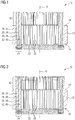
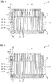
- Fig. 1 to 7 show a longitudinal cross section through a stator 10, wherein the different figures show the steps for twisting the winding head 11 of the stator 10.
- the stator 10 comprises a hollow cylindrical stator core 12, wherein the stator core 12 comprises a first end face 14 and a second end face 16. The first end face 14 is spaced apart to the second end face 16 in longitudinal direction 18 of the stator core 12.
- the longitudinal direction 18 of the stator core 12 corresponds to the longitudinal axis of the cylindrical stator core 12.
- a least a slot 20 is arranged on an inner surface 22 facing the longitudinal axis 18 of the stator core 12, wherein the slot 20 extends between the first end face 14 and the second end face 16 having a slot depth 24 in radial direction of the stator core 12.
- the stator core 12 comprises a plurality of slots 20 on the inner surface 22, wherein the slots 20 are spaced to each other in peripheral direction of the stator core 12.
- the stator 10 comprises at least a first conductor 26, a second conductor 28, a third conductor 30 and a fourth conductor 32 arranged in the slot 20 in radial direction of the stator core 12 next to each other.
- the first conductor 26 is arranged on an imaginary first circle having its circle center on the longitudinal axis 18 of the stator core 12.
- the second conductor 28 is arranged on an imaginary second circle, having a diameter smaller than the first circle, and having its circle center on the longitudinal axis 18 of the stator core 12.
- the third conductor 30 is arranged on an imaginary third circle having its circle center on the longitudinal axis 18 of the stator core 12, wherein the diameter of the imaginary third circle is smaller than the diameter of the imaginary second circle of the second conductors 28.
- the fourth conductor 32 is arranged on an imaginary fourth circle having the same circle center as the imaginary third circle, wherein the diameter of the imaginary fourth circle is smaller than the diameter of the imaginary third circle.
- the first conductor 26, the second conductor 28, the third conductor 30 and the fourth conductor 32 each comprises a plurality of conductors, wherein the plurality conductors are arranged in peripheral direction of the stator core 12 spaced to each other.
- the plurality of first conductors 26 defines a first conductor row 34 on the imaginary first circle.
- the second conductors 28 are arranged in peripheral direction of the stator core 12 spaced to each other on the second imaginary circle and define a second conductor row 36.
- the plurality of third conductors 30 defines a third conductor row 38 and the plurality of fourth conductors 32 defines a fourth conductor row 40.
- At least an end section 42 of the first, second third and fourth conductor 26, 28, 30, 32 protrudes and/or extends over the first end face 14 of the stator core 12.
- Fig. 2 shows the stator 10 known from Fig. 1 , wherein the end section 42 of the first conductor 26 is deflected and/or bend in radial direction of the stator core 12 by a split tool 44 according to Fig. 8 .
- the split tool 44 is designed as a split ring and shown in Fig. 8 .
- the end section 42 of the first conductor 26 is deflected and/or bend over its total length of the end section in radial direction outwardly.
- Fig. 3 show the stator 10 known from Fig. 2 wherein the end section 42 of the first conductor 26 is twisted angular in peripheral direction of the stator core 12 in a first direction which in the present example is a counterclockwise direction according to a view in the direction of the longitudinal axis 18 of the stator core 12.
- At least a part of the end section 42 of the first conductor 26 between the first end face 14 of the stator core 12 and a distal end 46 of the end section 42 of the first conductor 26 facing away from the first end face 14 is bend and/or necked in radial direction of the stator core 12 outward in such a way, that a distance between the end section 42 of the first conductor 26 and the end section 42 of the second conductor 28 in radial direction of the stator core 12 is at least partially enlarged with respect to the distance of the first conductor 26 and second conductor 28 in radial direction of the stator core 12, which are arranged in the slot 20.
- Fig. 4 shows the stator 10 known from Fig. 3 , wherein the end section 42 of the second conductor 28 is deflected and/or bend in radial direction of the stator core 12 by the split tool 44.
- the Split tool 44 is shown in Fig. 8 .
- the split tool 44 is different for bending end sections 42 of the different conductor rows.
- the split tool 44 for deflecting the end section 42 of the second conductor 28 might have a smaller diameter than the one for deflecting the end section 42 of the first conductor 26.
- Fig. 5 shows the stator 10 known from Fig. 4 , wherein the end section 42 of the second conductor 28 is twisted angular in peripheral direction of the stator core 12 in a second direction which is in the opposite direction of the first direction.
- the second direction is for example a clockwise direction.
- At least a part of the end section 42 of the second conductor 28 between the first end face 14 of the stator core 12 and a distal end 48 of the end section 42 of the second conductor 28 facing away from the first end face 14 is bend and/or necked in radial direction of the stator core 12 outward in such a way, that a distance between the end section 42 of the second conductor 28 and the end section 42 of the third conductor 30 in radial direction of the stator core 12 is at least partially enlarged with respect to the distance of the second conductor 28 and third conductor 30 in radial direction of the stator core 12, which are arranged in the slot 20.
- the radial distance between the distal end 46 of the first conductor 26 and the distal end 48 of the second conductor 28 corresponds to the radial distance of the first conductor 26 and the second conductor 28 being arranged in the slot 20 and only the twisted part of the end section 42 of the first conductor 26 between the distal end 46 and the first end face 14 of the stator core 12 is bend radially outward providing an enlarged gap in radial direction to the respective part of the end section 42 of the second conductor 28.
- the distal ends 46, 48 of the first conductor 26 and the second conductor 28 can be electrically connected easily.
- Fig. 6 shows the stator 10 known from Fig. 5 , wherein the end section 42 of the third conductor 30 is twisted in peripheral direction of the stator core 12 in the first direction, resp. counterclockwise, wherein at least a part of the end section 42 of the third conductor 30 between the first end face 14 of the stator core 12 and a distal end 50 of the end section 42 of the third conductor 28 facing away from the first end face 14 is bend and/or necked in radial direction of the stator core 12 outward in such a way, that a distance between the end section 42 of the third conductor 30 and the end section 42 of the fourth conductor 32 in radial direction of the stator core 12 is at least partially enlarged with respect to the distance of the third conductor 30 and the fourth conductor 32 in radial direction of the stator core 12, which are arranged in the slot 20.
- the end section 42 of the third conductor 30 is not deflected in radial direction of the stator core 12 by the split tool 44.
- Fig. 7 shows the stator 10 known from Fig. 6 , wherein the end section 42 of the fourth conductor 32 is twisted in peripheral direction of the stator core 12 in the second direction, resp. clockwise, without any bending or deflection in radial direction. Hence, the distal end 50 of the third conductor 30 can be easily connected to the distal end 52 of the fourth conductor 32.
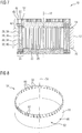
- Fig. 8 shows the split tool 44.
- the split tool 44 resp. split ring comprises a hollow cylindrical structure with a tooth shaped end 54 in longitudinal direction 56 of the split tool 44, wherein the tooth shaped end 54 comprises at least one receiving slot 58 for receiving the distal end 46, 48 of the end section 42 of the first conductor 26 or the second conductor 28 and a protrusion 60 next to the receiving slot 58 in peripheral direction of the split tool 44.
- the protrusion 60 comprises a sliding surface 62 arranged and designed in such a way, that for example when turning the split tool 44 in peripheral direction relative to the stator core 12, the distal end 46 of the end section 42 of the first conductor 26 received in the receiving slot 58 slides over the sliding surface 62 bending the end section 42 of the first conductor 26 radially outward.
- the end section 42 of the first conductor 26 can be shifted and/or moved in radial direction of the stator core 12 by turning the split tool 44 relative to the stator core 12 in peripheral direction of the stator core 12 easily.
- the end section 42 of the first conductor 26 slides at least partially along the sliding surface 62, which is preferably configured as a ramp.
- the turning resistance of the split tool 44 can be reduced and the end section 42 of the first conductor 26 can be at least partially deflected in radial direction of the stator core 12 gently.
- the diameter of the split tool 44 is different for defecting the first conductor 26, the second conductor 28 and the third conductor 30, respectively for deflecting the first conductor row 34, second conductor row 36 and third conductor row 38.
- Fig. 9 shows a hollow cylindrical winding core 64.
- the cylindrical winding core 64 comprises on an outer shell surface 66 a conductor guiding structure 68 on which the at least one cam 70 is arranged.
- the conductor guiding structure 68 comprises a conductor groove 72 extending in longitudinal direction 74 of the cylindrical winding core 64 for receiving the ends sections 42 of the conductors which should not be twisted during the twisting step.
- conductor guiding structure 68 comprises a plurality of conductor grooves 72 and a plurality of cams 70, wherein the conductor grooves 72 and the cams 70 are arranged alternating to each other. In other words, one conductor groove 72 is between two cams 70.
- the cam 70 comprises a sliding surface 76 arranged and configured in such a way that by twisting the end section 42 of the conductor to be twisted in peripheral direction of the stator core 12, the end section 42 is at least partially moved over the sliding surface 76 and thereby at least partially bend radially outward.
- the cam 70 comprises a ramp structure for guiding the end section 42 of the respective conductor 26, 28, 30 when twisted in peripheral direction of the stator core 12.
- the winding core 64 varies for guiding the different conductor rows of the first conductor 26, second conductor 28 and third conductor 30 at least in its diameter and the depth of the conductor groove 72 in radial direction of the cylindrical winding core 64.
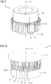
- Fig. 10 shows the stator 10 with the winding core 64 and the split tool 44.
- the winding core 64 is arranged on the stator core 12 in such a way, that the end sections 42 of the second 28, third 30 and fourth conductor 32 are guided in the conductor groove 72.
- the end section 42 of the first conductor 26 is arranged next to the cam 70 of the winding core 64.
- the split tool 44 is arranged on the winding core 64, wherein the distal end 46 of the end section 42 of the first conductor 26 is inserted in the receiving slot 58.
- the distal end 46 of the end section 42 of the first conductor 26 slides along the sliding surface 62 of the protrusion 60, bending and/or necking the end section 42 of the first conductor 26 in radial direction of the stator core 12 outwardly.
- Fig. 11 shows the stator 10 known from Fig. 10 wherein a twisting tool 77 is arranged on the stator 10 respectively the end section 42 of the first conductor 26.
- the twisting tool comprises at least one slot 78 at a distal end facing the stator core 12 for receiving the distal end 46 of the end section 42 of the first conductor 26.
- the slot 78 is configured as a cut. Preferably the cut reaches through the wall thickness of the hollow cylindrical twisting tool 77. Such a slot 78 is called an open slot.
- the twisting tool 77 is moved in peripheral direction of the stator core 12 for twisting the end section 42 of the first conductor 26, wherein during the twisting step, the end section 42 slides along the cam 70 of the winding core 64, bending and/or necking the part of the end section 42 of the first conductor 26, between the first end face 14 of the stator core 12 and the distal end 46 of the end section 42 facing away from the first end face 14, in radial direction of the stator core 12 in such a way, that the distance between the end section 42 of the first conductor 26 and the end section 42 of the second conductor 28 in radial direction of the stator core 12 is at least partially enlarged with respect to the distance of the first 26 and second conductor 28 in radial direction of the stator core 12,
- the twisting tool 77 varies for twisting the different conductor rows of the first conductor 26, second conductor 28, third conductor 30 and fourth conductor 32 at least in its diameter.
Landscapes
- Engineering & Computer Science (AREA)
- Manufacturing & Machinery (AREA)
- Power Engineering (AREA)
- Manufacture Of Motors, Generators (AREA)
- Windings For Motors And Generators (AREA)
Abstract
Description
- The invention relates to a method for twisting a winding head of a stator, wherein during a twisting process of an end section of conductors of the winding resp. stator, protruding over an end face of a stator core, a distance of the conductors to each other in radial direction of the stator core is at least partially enlarged. Furthermore, the invention relates to a device for twisting a winding head of a stator. A further part of the invention is a stator for an electrical machine.
- Methods for twisting a winding head of a stator with hairpin, or I-pin technology are well known. Usually, the stator comprises a stator core and a plurality of conductors, which are arranged in slots of the stator core. The stator core usually comprises a plurality of lamination stacks, which are stacked together forming the stator core. The slots are arranged on an inner surface of the stator core, extending between a first end face of the stator and a second end face of the stator being spaced to the first end face. Furthermore, the slots are arranged in peripheral direction of the stator spaced to each other. A first row of conductors and a second row of conductors are arranged in the slots, wherein the first conductors and the second conductors are arranged in radial direction of the stator core next to each other. The conductors of the first row and the second row protrude over the first end face of the stator core. These conductor ends are twisted in peripheral direction of the stator core wherein the first conductor ends are twisted clockwise, and the second conductor ends are twisted counterclockwise. During the twisting process of the conductor ends, a coating of the conductors is stressed by friction and might crack. For avoiding any shorting, an isolation paper is placed between the first row and the second row of the conductors. However, the arrangement of an isolation paper is sometimes difficult and time consuming.
-
EP 1 376 818 A2 describes a method for twisting a winding head of a stator having a radial gap between the conductors. According to the described method, a tail side coil end includes a plurality of tail conductor pairs sequentially disposed with predetermined radial gaps. The radial gaps between the conductor pairs are widened near the end surface of a stator core. This arrangement prevents adjacent tail joint portions or adjacent slanting portions from undesirably contacting with each other, thereby adequately maintaining electric insulation between the tail conductor pairs and improving the space factor of the slot. However, the document does not describe how the radial gaps between the conductor pairs are widened and how this gap can be reliably shaped during and/or after the twisting process of the conductor pairs. - It is an object of the present invention to provide a method and a device for twisting a winding head of a stator, wherein the danger of shorting of the twisted conductor ends of the stator can be easily reduced.
- This object is achieved by the subject matter of the independent claims. Preferred embodiments of the invention are subject matter of the dependent claims or described hereinafter.
- According to the invention, a method for twisting a winding head of a stator is provided, comprising the following steps:
- Providing a hollow cylindrical stator core having a first end face and a second end face being spaced apart to each other in longitudinal direction of the stator core, and an inner surface facing a longitudinal axis of the stator core with a least one slot on the inner surface extending between the first end face and the second end face having a slot depth in radial direction of the stator core;
- Positioning at least a first conductor and a second conductor in the slot, arranged in radial direction of the stator core next to each other, wherein at least an end section of the conductors protrudes over the first end face of the stator core;
- Arranging a winding core, having at least one cam protruding in radial direction outward of the winding core, on the stator, the stator core and/or the first end face;
- Twisting the end section of the first conductor in peripheral direction of the stator core, wherein the end section of the first conductor is moved over the cam, bending and/or necking a part of the end section of the first conductor, between the first end face of the stator core and a distal end of the end section facing away from the first end face, in radial direction of the stator core in such a way, that a distance between the end section of the first conductor and the end section of the second conductor in radial direction of the stator core is at least partially enlarged with respect to the distance of the first and second conductor in radial direction of the stator core, which are arranged in the slot.
- In other words, according to that method, a hollow cylindrical stator core is provided. Usually, the stator core comprises a plurality of lamination stacks, arranged next to each other, forming the stator core. The stator core comprises a first end face and a second end face, wherein the first end face is spaced apart to the second end face in longitudinal direction of the stator core. The longitudinal direction of the stator core corresponds to the longitudinal axis of the cylindrical stator core. At least a slot is arranged on an inner surface of the stator core facing the longitudinal axis of the stator core, wherein the slot extends between the first end face and the second end face having a slot depth in radial direction of the stator core. Preferably, the stator core comprises a plurality of slots on the inner surface, wherein the slots are spaced to each other in peripheral direction of the stator core.
- At least a first conductor and a second conductor are arranged in the slot in radial direction of the stator core next to each other. In other words, the first conductor is arranged on an imaginary first circle having its circle center on the longitudinal axis of the stator core. The second conductor is arranged on an imaginary second circle, having a diameter smaller than the first circle, and having its circle center on the longitudinal axis of the stator core. At least an end section of the first conductor and an end section of the second conductor protrude and/or extend over the first end face of the stator core. Preferably, a plurality of first conductors and a plurality of second conductors are provided. More preferably, the plurality of first conductors is arranged in peripheral direction of the stator core on the first imaginary circle, wherein the plurality of first conductors defines a first conductor row. The plurality of first conductors might be arranged next to each other and/or spaced apart to each other in peripheral direction of the stator core. The plurality of the first conductors can be arranged in such a way that only one conductor of the first conductors is arranged in the slot of the stator core. However, it is also possible that more than one first conductor is arranged in the slot of the stator core in peripheral direction of the stator core. Preferably, the plurality of second conductors is arranged in peripheral direction on the first imaginary circle, wherein the plurality of second conductors defines a second conductor row. More preferably, the plurality of second conductors is arranged next to each other and/or spaced apart to each other in peripheral direction of the stator core. The plurality of the second conductors can be arranged in such a way that only one conductor of the second conductors is arranged in the slot of the stator core. However, it is also possible that more than one second conductor is arranged in the slot of the stator core in peripheral direction of the stator core.
- A winding core is arranged on the stator, the stator core and/or the first end face of the stator core. In other words, the winding core is arranged on the stator core resp. the end face in longitudinal direction of the stator core. The winding core might have a cylindrical or a hollow cylindrical structure and/or shape. The winding core comprises at least one cam. Preferably, the cam protrudes in radial direction outwardly. However, it is also possible that the cam protrudes in radial direction inwardly. Preferably, the winding core comprises a plurality of cams wherein the cams are spaced to each other in peripheral direction of the winding core. The winding core can also be named as a necking tool.
- After arranging the winding core on the stator, resp. the end face of the stator core, the end section of the first conductor is twisted in peripheral direction of the stator core. Due to that twisting process, the end section of the first conductor is moved over the cam, wherein a part of the end section of the first conductor, between the first end face of the stator core and a distal end of the end section of the first conductor facing away from the first end face, is bend and/or necked in radial direction of the stator core in such a way, that a distance between the end section of the first conductor and the end section of the second conductor in radial direction of the stator core is at least partially enlarged with respect to the distance of the first and second conductor in radial direction of the stator core, which are arranged in the slot. Thus, due to the winding core and especially the cam arranged on the winding core, the end section of the first conductor is bend and/or necked either in radial direction outwardly or in radial direction inwardly, enlarging the radial gap between the end section of the first conductor and the end section of the second conductor. Hence, the danger of shorting of the twisted conductor ends of the stator can be easily reduced.
- The conductors usually have a rectangular shape in a cross section. However, the conductors can also have a round shape or any other type of cross section.
- The winding core resp. the necking tool is only used for the twisting process for bending and/or necking the end section of the first conductor. After twisting the end section of the first conductor in peripheral direction of the stator core, the winding core is removed from the stator.
- In a preferred embodiment of the invention, only the part of the end section between the distal end of the end section of the first conductor and the first end face of the stator comprises an enlarged distance to the end section of the second conductor in radial direction of the stator core. For example, the radial distance between the distal end of the first conductor and the distal end of the second conductor corresponds to the radial distance of the first conductor and the second conductor being arranged in the slot and only the twisted part of the end section of the first conductor between the distal end and the first end face of the stator is bend and/or necked radially outward providing an enlarged gap in radial direction to the respective part of the end section of the second conductor. Hence, the distal ends of the first conductor and the second conductor can be electrically connected easily.
- In a preferred embodiment of the invention, the end section of the first conductor is at least partially deflected and/or bend in radial direction of the stator core by a split tool. It is conceivable that the end section of the first conductor is deflected and/or bend over its total length in radial direction outwardly. The split tool is inserted in longitudinal direction of the stator core between the end section of the first conductor and the end section of the second conductor. Due to a movement of the split tool in peripheral direction relative to the stator core, the end section of the first conductor is at least partially bend in radial direction outwardly. Preferably, the deflecting step is carried out prior to the twisting step. Hence, by deflecting and/or bending the end section of the first conductor in radial direction of the stator, the distal end of the end section can be shifted into a slot of a twisting tool for twisting the end section of the first conductor in peripheral direction of the stator core.
- The split tool might be arranged and designed in such a way that the end section of the first conductor is deflected and/or bend over its total length in radial direction outwardly. According to a preferred embodiment of the invention, the split tool is designed as a split ring. The split ring can be easily arranged between the end section of the first conductor and the end section of the second conductor and shifted in peripheral direction of the stator core for deflecting the end section of the respective conductor in radial direction.
- In a preferred embodiment of the invention, the end section of the first conductor is twisted in peripheral direction of the stator core by a twisting tool having at least one slot for receiving the distal end of the end section. Preferably, the twisting tool comprises a plurality of slots being spaced apart in peripheral direction of the twisting tool, wherein the slots are arranged and configured for receiving the distal ends of the end sections of the conductors of the first conductor row.
- It is conceivable that the at least one slot comprises an opening on an end surface of the twisting tool facing the distal end of the end section of the first conductor. Such a slot, having only one opening at the end surface of the twisting tool is called a closed slot. Hence, after the end section of the first conductor is deflected in radial direction, the twisting tool is positioned in such a way that the end of the first conductor enters at least partially the slot via the opening. After entering into the slot, the twisting tool is twisted in peripheral direction of the stator core.
- According to a preferred embodiment of the invention, the slot is configured as a cut. Preferably, the cut reaches through the wall thickness of the hollow cylindrical twisting tool. Such a slot is called an open slot. Hence, for example, the twisting tool is arranged on the end section of the first conductor before deflecting the end section in radial direction outwardly. After deflecting the end section of the first conductor in radial direction outwardly, the distal end of the end section of the first conductor is deflected and/or shifted into the open slot of the twisting tool. After entering the slot by the defection of the end section of the first conductor end, the twisting tool is twisted in peripheral direction of the stator core.
- In a preferred embodiment of the invention, the twisting step is carried out time shifted to the splitting step. In other words, the splitting and/or deflecting step for at least partially deflecting the end section of the first conductor in radial direction is carried out prior to the twisting step. However, after deflecting the end section of the first conductor radially outward in such a way that the distal end of the end section of the first conductor is defected and/or shifted into the open slot of the twisting tool, the split tool and the twisting tool are twisted together, respectively simultaneously, in the same direction.
- It is conceivable that the stator comprises further conductors resp. conductor rows. Preferably, the stator comprises a third conductor and a fourth conductor. In other words, the third conductor is arranged on an imaginary third circle having its circle center on the longitudinal axis of the stator core. The diameter of the imaginary third circle is smaller than the diameter of the imaginary second circle of the second conductors. The fourth conductor is arranged on an imaginary fourth circle having the same circle center as the imaginary third circle, wherein the diameter of the fourth circle is smaller than the diameter of the imaginary third circle.
- Preferably, a plurality of third conductors and a plurality of fourth conductors are provided. The third conductors arranged in peripheral direction of the stator core spaced to each other on the third imaginary circle, wherein the plurality of third conductors defines a third conductor row. The fourth conductors are arranged in peripheral direction of the stator core spaced to each other on the fourth imaginary circle, wherein the plurality of fourth conductors defines a fourth conductor row.
- Preferably, the plurality of third conductors is arranged in peripheral direction of the stator core on the third imaginary circle, wherein the plurality of third conductors defines a third conductor row. More preferably, the plurality of third conductors is arranged next to each other and/or spaced apart to each other in peripheral direction of the stator core. The plurality of the third conductors can be arranged in such a way that only one conductor of the third conductors is arranged in the slot of the stator core. However, it is also possible that more than one third conductor is arranged in the slot of the stator core in peripheral direction of the stator core.
- Preferably, the plurality of fourth conductors is arranged in peripheral direction of the stator core on the fourth imaginary circle, wherein the plurality of fourth conductors defines a fourth conductor row. More preferably, the plurality of fourth conductors is arranged next to each other and/or spaced apart to each other in peripheral direction of the stator core. The plurality of the fourth conductors can be arranged in such a way that only one conductor of the fourth conductors is arranged in the slot of the stator core. However, it is also possible that more than one fourth conductor is arranged in the slot of the stator core in peripheral direction of the stator core.
- The first conductor, the second conductor and the third conductor can be deflected and/or twisted according to the above described method wherein, for deflecting and or twisting the respective conductor and/or conductor row, the diameter of the winding core, split tool and/or twisting tool has to be adjusted respectively different tools have to be used.
- The invention further concerns to a twisting device for twisting a winding head of a stator, comprising
- a holding device for holding a hollow cylindrical stator core having a first end face and a second end face being spaced apart to each other in longitudinal direction of the stator core, and an inner surface facing a longitudinal axis of the stator core with a least one slot on the inner surface extending between first end face and the second end face having a slot depth in radial direction of the stator core, wherein at least a first conductor and a second conductor is positioned in the slot in radial direction of the stator core next to each other, wherein at least an end section of the conductors protrudes and/or extends over the first end face of the stator core,
- a winding core, having at least one cam protruding in radial direction of the winding core, arrangeable on the stator, the stator core and/or the first end face of the stator core in such a way, that the cam is positioned next to the protruding end section in peripheral direction of the stator core, and
- a twisting tool having at least one slot for receiving a distal end of the end section of the first conductor facing away from the first end face for twisting the end section of the first conductor in peripheral direction of the stator core, wherein by twisting the end section of the first conductor in peripheral direction of the stator core, the end section of the first conductor is moved over the cam, bending the end section of the first conductor radially outward in such a way, that a distance between the end section of the first conductor and the end section of the second conductor in radial direction of the stator is at least partially enlarged with respect to the distance of the first and second conductor in radial direction of the stator core, which are arranged in the slot.
- In other words, a twisting device for twisting a winding head of a stator is provided for caring out the above described twisting method, wherein the danger of shorting of the twisted conductor ends of the stator can be easily reduced.
- According to a preferred embodiment of the invention, the cam comprises a sliding surface arranged and configured in such a way that by twisting the end section of the first conductor in peripheral direction of the stator core, the end section is at least partially moved over the sliding surface and thereby at least partially bend radially outward for necking the first conductor. Hence, the cam comprises a ramp structure for guiding the end section of the first conductor when twisted in peripheral direction or the stator core. Thus, the turning resistance of the twisting tool in peripheral direction of the stator core can be reduced. Furthermore, the end section of the first conductor can be bend in radial direction carefully and/or gently for avoiding any damage of an isolation on the first conductor.
- In a preferred embodiment of the invention, the winding core comprises on an outer shell surface a conductor guiding structure on which the at least one cam is arranged, wherein the conductor guiding structure comprises a conductor groove extending in longitudinal direction of the winding core for receiving the second conductor. Preferably, the conductor guiding structure comprises a plurality of grooves and a plurality of cams, wherein the grooves and the cams are arranged alternating to each other. In other words, one groove is between two cams. The groove is designed and arranged for receiving the end section of the conductor which is not twisted by the twisting tool, wherein the end section of the conductor for twisting by the twisting tool is arranged next to the cam.
- In a preferred embodiment of the invention, the twisting devise comprises a split tool with a tooth shaped end in longitudinal direction of the split tool, wherein the tooth shaped end comprises at least one receiving slot for receiving the distal end of the end section of the first conductor and a protrusion next to the receiving slot in peripheral direction of the split tool having a sliding surface arranged and designed in such a way, that when turning the split tool in peripheral direction relative to the stator core, the distal end of the end section of the first conductor received in the receiving slot slides over the sliding surface bending the end section of the first conductor radially outward. Hence, the end section of the first conductor can be easily shifted and/or moved in radial direction of the stator core by turning the split tool relative to the stator core in peripheral direction. The end section of the first conductor slides at least partially along the sliding surface, which is preferably configured as a ramp. Thus, the turning resistance of the split tool can be reduced and the end section of the first conductor can be at least partially deflected in radial direction of the stator core gently.
- In a preferred embodiment of the invention, the slot of the twisting tool is open on an inner surface facing the longitudinal axis of the twisting tool, respectively facing the end section of the first conductor. Hence, preferably the twisting tool is arranged on the end section of the first conductor before deflecting the end section in radial direction outwardly. After deflecting the end section of the first conductor in radial direction outwardly, the distal end of the end section of the first conductor is deflected and/or shifted into the slot of the twisting tool.
- In a preferred embodiment of the invention, the split tool comprises an insertion opening on an outer shell surface of the split tool for receiving a turning lever, and the twisting tool comprises an insertion slit, larger than the insertion opening of the split tool, designed in such a way that a tuning lever can reach through the insertion slit into the insertion opening. Hence, the twisting step can be carried out time shifted to the splitting and/or deflecting step. A turning lever can reach through the insertion slit to the insertion opening. Since, the insertion slit is larger than the insertion opening, when turning the turning lever, the split tool in moved in radial direction shifting and/or deflecting the end section of the first conductor in radial direction, wherein the distal end of the end section of the first conductor introduces into the slot of the twisting tool. After the distal end section of the first conductor is received in the slot of the twisting tool, the split tool and the twisting tool are turned in peripheral direction of the stator core simultaneously by the turning lever.
- In a further aspect of the invention, a stator for an electrical machine, preferably of an at least partially electric driven vehicle, is provided, comprising
- a hollow cylindrical stator core having a first end face and a second end face being spaced apart to each other in longitudinal direction of the stator core, and an inner surface facing a longitudinal axis of the stator core with a least one slot on the inner surface extending between first end face and the second end face having a slot depth in radial direction of the stator core radially outward facing,
- at least a first conductor and a second conductor arranged in the slot in radial direction of the stator core next to each other, wherein at least an end section of the conductors protrudes and/or extends over the first end face of the stator core, wherein
- the end section of the first conductor is twisted in peripheral direction of the stator core in a first direction and the end section of the second conductor is twisted in peripheral direction of the stator core in a second direction, which is in opposite direction of the first direction, and
- at least a part of the end section of the first conductor between the first end face of the stator core and a distal end of the end section facing away from the first end face is bend and/or necked in radial direction of the stator core outward in such a way, that a distance between the end section of the first conductor and the end section of the second conductor in radial direction of the stator core is at least partially enlarged with respect to the distance of the first and second conductor in radial direction of the stator core, which are arranged in the slot.
- In other words, a stator for an electrical machine is provided, wherein the danger of shorting of the twisted conductor ends of the stator can be easily reduced.
- In a preferred embodiment of the invention, only the part of the end section between the distal end of the end section of the first conductor and the first end face of the stator core comprises an enlarged distance to the end section of the second conductor in radial direction of the stator core. For example, the radial distance between the distal end of the first conductor and the distal end of the second conductor corresponds to the radial distance of the first conductor and the second conductor being arranged in the slot and only the twisted part of the end section of the first conductor between the distal end and the first end face of the stator core is bend radially outward providing an enlarged gap in radial direction to the respective part of the end section of the second conductor. Hence, the distal ends of the first conductor and the second conductor can be easily connected.
- The features and advantages of the method do also apply to the device and the stator. The features and advantages of the device do also apply to the method and the stator. Furthermore, the features and advantages of the stator do also apply to the method and the device.
- These and other aspects of the invention will be apparent from and elucidated with reference to the embodiments as per the drawings described hereinafter. In the following description, exemplary embodiments of the invention are explained with reference to the accompanying schematic drawing.
- Fig. 1 to 7
- a longitudinal cross section through a stator according to the invention showing the steps for twisting the winding head of the stator,
- Fig. 8
- a three-dimensional view of a split tool according to the invention,
- Fig. 9
- a three-dimensional view of a winding core according to the invention,
- Fig. 10
- a three-dimensional view of the stator with the winding core and the split tool according to the invention,
- Fig. 11
- a three-dimensional view of the stator with the winding core, the split tool and the twisting tool according to the invention.
-
Fig. 1 to 7 show a longitudinal cross section through astator 10, wherein the different figures show the steps for twisting the winding head 11 of thestator 10. - The
stator 10 comprises a hollowcylindrical stator core 12, wherein thestator core 12 comprises afirst end face 14 and asecond end face 16. Thefirst end face 14 is spaced apart to thesecond end face 16 inlongitudinal direction 18 of thestator core 12. Thelongitudinal direction 18 of thestator core 12 corresponds to the longitudinal axis of thecylindrical stator core 12. A least aslot 20 is arranged on aninner surface 22 facing thelongitudinal axis 18 of thestator core 12, wherein theslot 20 extends between thefirst end face 14 and thesecond end face 16 having aslot depth 24 in radial direction of thestator core 12. Presently, thestator core 12 comprises a plurality ofslots 20 on theinner surface 22, wherein theslots 20 are spaced to each other in peripheral direction of thestator core 12. - The
stator 10 comprises at least a first conductor 26, a second conductor 28, a third conductor 30 and a fourth conductor 32 arranged in theslot 20 in radial direction of thestator core 12 next to each other. In other words, the first conductor 26 is arranged on an imaginary first circle having its circle center on thelongitudinal axis 18 of thestator core 12. The second conductor 28 is arranged on an imaginary second circle, having a diameter smaller than the first circle, and having its circle center on thelongitudinal axis 18 of thestator core 12. The third conductor 30 is arranged on an imaginary third circle having its circle center on thelongitudinal axis 18 of thestator core 12, wherein the diameter of the imaginary third circle is smaller than the diameter of the imaginary second circle of the second conductors 28. The fourth conductor 32 is arranged on an imaginary fourth circle having the same circle center as the imaginary third circle, wherein the diameter of the imaginary fourth circle is smaller than the diameter of the imaginary third circle. - Presently, the first conductor 26, the second conductor 28, the third conductor 30 and the fourth conductor 32 each comprises a plurality of conductors, wherein the plurality conductors are arranged in peripheral direction of the
stator core 12 spaced to each other. The plurality of first conductors 26 defines a first conductor row 34 on the imaginary first circle. The second conductors 28 are arranged in peripheral direction of thestator core 12 spaced to each other on the second imaginary circle and define a second conductor row 36. The plurality of third conductors 30 defines a third conductor row 38 and the plurality of fourth conductors 32 defines a fourth conductor row 40. - At least an
end section 42 of the first, second third and fourth conductor 26, 28, 30, 32 protrudes and/or extends over thefirst end face 14 of thestator core 12. -
Fig. 2 shows thestator 10 known fromFig. 1 , wherein theend section 42 of the first conductor 26 is deflected and/or bend in radial direction of thestator core 12 by asplit tool 44 according toFig. 8 . Thesplit tool 44 is designed as a split ring and shown inFig. 8 . Theend section 42 of the first conductor 26 is deflected and/or bend over its total length of the end section in radial direction outwardly. -
Fig. 3 show thestator 10 known fromFig. 2 wherein theend section 42 of the first conductor 26 is twisted angular in peripheral direction of thestator core 12 in a first direction which in the present example is a counterclockwise direction according to a view in the direction of thelongitudinal axis 18 of thestator core 12. At least a part of theend section 42 of the first conductor 26 between thefirst end face 14 of thestator core 12 and adistal end 46 of theend section 42 of the first conductor 26 facing away from thefirst end face 14 is bend and/or necked in radial direction of thestator core 12 outward in such a way, that a distance between theend section 42 of the first conductor 26 and theend section 42 of the second conductor 28 in radial direction of thestator core 12 is at least partially enlarged with respect to the distance of the first conductor 26 and second conductor 28 in radial direction of thestator core 12, which are arranged in theslot 20. -
Fig. 4 shows thestator 10 known fromFig. 3 , wherein theend section 42 of the second conductor 28 is deflected and/or bend in radial direction of thestator core 12 by thesplit tool 44. TheSplit tool 44 is shown inFig. 8 . However, thesplit tool 44 is different for bendingend sections 42 of the different conductor rows. For example, thesplit tool 44 for deflecting theend section 42 of the second conductor 28 might have a smaller diameter than the one for deflecting theend section 42 of the first conductor 26. -
Fig. 5 shows thestator 10 known fromFig. 4 , wherein theend section 42 of the second conductor 28 is twisted angular in peripheral direction of thestator core 12 in a second direction which is in the opposite direction of the first direction. The second direction is for example a clockwise direction. At least a part of theend section 42 of the second conductor 28 between thefirst end face 14 of thestator core 12 and adistal end 48 of theend section 42 of the second conductor 28 facing away from thefirst end face 14 is bend and/or necked in radial direction of thestator core 12 outward in such a way, that a distance between theend section 42 of the second conductor 28 and theend section 42 of the third conductor 30 in radial direction of thestator core 12 is at least partially enlarged with respect to the distance of the second conductor 28 and third conductor 30 in radial direction of thestator core 12, which are arranged in theslot 20. - Furthermore, only the part of the
end section 42 between thedistal end 46 ofend section 42 of the first conductor 26 and thefirst end face 14 of thestator 12 comprises an enlarged distance to theend section 42 of the second conductor 28 in radial direction of thestator core 12. Hence, the radial distance between thedistal end 46 of the first conductor 26 and thedistal end 48 of the second conductor 28 corresponds to the radial distance of the first conductor 26 and the second conductor 28 being arranged in theslot 20 and only the twisted part of theend section 42 of the first conductor 26 between thedistal end 46 and thefirst end face 14 of thestator core 12 is bend radially outward providing an enlarged gap in radial direction to the respective part of theend section 42 of the second conductor 28. Thus, the distal ends 46, 48 of the first conductor 26 and the second conductor 28 can be electrically connected easily. -
Fig. 6 shows thestator 10 known fromFig. 5 , wherein theend section 42 of the third conductor 30 is twisted in peripheral direction of thestator core 12 in the first direction, resp. counterclockwise, wherein at least a part of theend section 42 of the third conductor 30 between thefirst end face 14 of thestator core 12 and adistal end 50 of theend section 42 of the third conductor 28 facing away from thefirst end face 14 is bend and/or necked in radial direction of thestator core 12 outward in such a way, that a distance between theend section 42 of the third conductor 30 and theend section 42 of the fourth conductor 32 in radial direction of thestator core 12 is at least partially enlarged with respect to the distance of the third conductor 30 and the fourth conductor 32 in radial direction of thestator core 12, which are arranged in theslot 20. However, theend section 42 of the third conductor 30 is not deflected in radial direction of thestator core 12 by thesplit tool 44. -
Fig. 7 shows thestator 10 known fromFig. 6 , wherein theend section 42 of the fourth conductor 32 is twisted in peripheral direction of thestator core 12 in the second direction, resp. clockwise, without any bending or deflection in radial direction. Hence, thedistal end 50 of the third conductor 30 can be easily connected to thedistal end 52 of the fourth conductor 32. -
Fig. 8 shows thesplit tool 44. Thesplit tool 44, resp. split ring comprises a hollow cylindrical structure with a tooth shapedend 54 inlongitudinal direction 56 of thesplit tool 44, wherein the tooth shapedend 54 comprises at least one receivingslot 58 for receiving thedistal end end section 42 of the first conductor 26 or the second conductor 28 and aprotrusion 60 next to the receivingslot 58 in peripheral direction of thesplit tool 44. Theprotrusion 60 comprises a slidingsurface 62 arranged and designed in such a way, that for example when turning thesplit tool 44 in peripheral direction relative to thestator core 12, thedistal end 46 of theend section 42 of the first conductor 26 received in the receivingslot 58 slides over the slidingsurface 62 bending theend section 42 of the first conductor 26 radially outward. Hence, theend section 42 of the first conductor 26 can be shifted and/or moved in radial direction of thestator core 12 by turning thesplit tool 44 relative to thestator core 12 in peripheral direction of thestator core 12 easily. Theend section 42 of the first conductor 26 slides at least partially along the slidingsurface 62, which is preferably configured as a ramp. Thus, the turning resistance of thesplit tool 44 can be reduced and theend section 42 of the first conductor 26 can be at least partially deflected in radial direction of thestator core 12 gently. - The diameter of the
split tool 44 is different for defecting the first conductor 26, the second conductor 28 and the third conductor 30, respectively for deflecting the first conductor row 34, second conductor row 36 and third conductor row 38. -
Fig. 9 shows a hollowcylindrical winding core 64. The cylindrical windingcore 64 comprises on an outer shell surface 66 aconductor guiding structure 68 on which the at least onecam 70 is arranged. Theconductor guiding structure 68 comprises aconductor groove 72 extending in longitudinal direction 74 of the cylindrical windingcore 64 for receiving theends sections 42 of the conductors which should not be twisted during the twisting step. Presently,conductor guiding structure 68 comprises a plurality ofconductor grooves 72 and a plurality ofcams 70, wherein theconductor grooves 72 and thecams 70 are arranged alternating to each other. In other words, oneconductor groove 72 is between twocams 70. - The
cam 70 comprises a slidingsurface 76 arranged and configured in such a way that by twisting theend section 42 of the conductor to be twisted in peripheral direction of thestator core 12, theend section 42 is at least partially moved over the slidingsurface 76 and thereby at least partially bend radially outward. Hence, thecam 70 comprises a ramp structure for guiding theend section 42 of the respective conductor 26, 28, 30 when twisted in peripheral direction of thestator core 12. - The winding
core 64 varies for guiding the different conductor rows of the first conductor 26, second conductor 28 and third conductor 30 at least in its diameter and the depth of theconductor groove 72 in radial direction of the cylindrical windingcore 64. -
Fig. 10 shows thestator 10 with the windingcore 64 and thesplit tool 44. The windingcore 64 is arranged on thestator core 12 in such a way, that theend sections 42 of the second 28, third 30 and fourth conductor 32 are guided in theconductor groove 72. Theend section 42 of the first conductor 26 is arranged next to thecam 70 of the windingcore 64. Furthermore, thesplit tool 44 is arranged on the windingcore 64, wherein thedistal end 46 of theend section 42 of the first conductor 26 is inserted in the receivingslot 58. When turning thesplit tool 44 in peripheral direction of thestator core 12, thedistal end 46 of theend section 42 of the first conductor 26 slides along the slidingsurface 62 of theprotrusion 60, bending and/or necking theend section 42 of the first conductor 26 in radial direction of thestator core 12 outwardly. -
Fig. 11 shows thestator 10 known fromFig. 10 wherein atwisting tool 77 is arranged on thestator 10 respectively theend section 42 of the first conductor 26. The twisting tool comprises at least oneslot 78 at a distal end facing thestator core 12 for receiving thedistal end 46 of theend section 42 of the first conductor 26. Theslot 78 is configured as a cut. Preferably the cut reaches through the wall thickness of the hollowcylindrical twisting tool 77. Such aslot 78 is called an open slot. When deflecting theend section 42 of the first conductor 26 in radial direction outwardly, thedistal end 46 of theend section 42 of the first conductor 26 is deflected and/or shifted into theopen slot 78 of the twistingtool 77. After that, the twistingtool 77 is moved in peripheral direction of thestator core 12 for twisting theend section 42 of the first conductor 26, wherein during the twisting step, theend section 42 slides along thecam 70 of the windingcore 64, bending and/or necking the part of theend section 42 of the first conductor 26, between thefirst end face 14 of thestator core 12 and thedistal end 46 of theend section 42 facing away from thefirst end face 14, in radial direction of thestator core 12 in such a way, that the distance between theend section 42 of the first conductor 26 and theend section 42 of the second conductor 28 in radial direction of thestator core 12 is at least partially enlarged with respect to the distance of the first 26 and second conductor 28 in radial direction of thestator core 12, which are arranged in theslot 20. - The twisting
tool 77 varies for twisting the different conductor rows of the first conductor 26, second conductor 28, third conductor 30 and fourth conductor 32 at least in its diameter. -
- 10
- Stator
- 12
- Stator core
- 14
- First end face of the stator core
- 16
- Second end face of the stator core
- 18
- Longitudinal direction / axis of the stator core
- 20
- Slot
- 22
- Inner surface
- 24
- Slot depth
- 26
- First conductor
- 28
- Second conductor
- 30
- Third conductor
- 32
- Fourth conductor
- 34
- First conductor row
- 36
- Second conductor row
- 38
- Third conductor row
- 40
- Fourth conductor row
- 42
- End section of conductor
- 44
- Split tool
- 46
- Distal end of end section of first conductor
- 48
- Distal end of end section of second conductor
- 50
- Distal end of end section of third conductor
- 52
- Distal end of end section of fourth conductor
- 54
- Tooth shaped end
- 56
- Longitudinal direction of split tool
- 58
- Receiving slot
- 60
- Protrusion
- 62
- Sliding surface
- 64
- Winding core
- 66
- Outer shell surface
- 68
- Guiding structure
- 70
- Cam
- 72
- Conductor groove
- 74
- Longitudinal direction of winding core
- 76
- Sliding surface cam
- 77
- Twisting tool
- 78
- Slot
- 80
- Insertion opening
- 82
- Outer shell surface of split tool
Claims (15)
- Method for twisting a winding head of a stator (10), comprising the following steps:Providing a hollow cylindrical stator core (12) having a first end face (14) and a second end face (16) being spaced apart to each other in longitudinal direction (18) of the stator core (12), and an inner surface (22) facing a longitudinal axis (18) of the stator core (12) with a least one slot (20) on the inner surface (22) extending between the first end face (14) and the second end face (16) having a slot depth (24) in radial direction of the stator core (12);positioning at least a first conductor (26) and a second conductor (28) in the slot (20) in radial direction of the stator core (12) next to each other, wherein at least an end section (42) of the conductors (26, 28) protrudes and/or extends over the first end face (14) of the stator core (12);arranging a winding core (64), having at least one cam (70) protruding in radial direction outward of the winding core (64), on the stator core (12) and/or the first end face (14);twisting the end section (42) of the first conductor (26) in peripheral direction of the stator core (12), wherein the end section (42) of the first conductor (26) is moved over the cam (70), bending and/or necking a part of the end section (42) of the first conductor (26), between the first end face (14) of the stator core (12) and a distal end (46) of the end section (42) of the first conductor (26) facing away from the first end face (14), in radial direction of the stator core (12) in such a way, that a distance between the end section (42) of the first conductor (26) and the end section (42) of the second conductor (28) in radial direction of the stator core (12) is at least partially enlarged with respect to the distance of the first (26) and second conductor (28) in radial direction of the stator core (12), which are arranged in the slot (20).
- Method according to claim 1, wherein only the part of the end section (42) between the distal end (46) of the end section (42) of the first conductor (26) and the first end face (14) of the stator core (12) comprises an enlarged distance to the end section (42) of the second conductor (28) in radial direction of the stator core (12).
- Method according to claim 1 or 2, characterized in that, the end section (42) of the first conductor (26) is at least partially deflected and/or bend in radial direction of the stator core (12) by a split tool (44).
- Method according to claim 3, characterized in that, the deflecting step is carried out prior to the twisting step.
- Method according to claim 3 or 4, characterized in that, by deflecting and/or bending the end section (42) of the first conductor (26) in radial direction of the stator core (12), the distal end (46) of the end section (42) is deflected and/or shifted into a slot (78) of a twisting tool (77) for twisting the end section (42) of the first conductor (26) in peripheral direction of the stator core (12).
- Method according to one of the previous claims, characterized in that the end section (42) of the first conductor (26) is twisted in peripheral direction of the stator core by a twisting tool (77) having at least one slot (78) for receiving the distal end (46) of the end section (42).
- Characterized in that, the twisting process is carried out time shifted to the splitting step.
- Twisting device for twisting a winding head of a stator (10), comprisinga holding device for holding a hollow cylindrical stator core (12) having a first end face (14) and a second end face (16) being spaced apart to each other in longitudinal direction (18) of the stator core (12), and an inner surface (22) facing a longitudinal axis of the stator core (12) with a least one slot (20) on the inner surface (22) extending between first end face (14) and the second end face (16) having a slot depth (24) in radial direction of the stator core (12), wherein at least a first conductor (26) and a second conductor (28) is positioned in the slot (20) in radial direction of the stator core (12) next to each other, wherein at least an end section (42) of the conductors (26, 28) protrudes and/or extends over the first end face (14) of the stator core (12),a winding core (64), having at least one cam (70) protruding in radial direction of the winding core (64), arrangeable on the stator core (12) and/or the first end face (14) of the stator core (12) in such a way that the cam (70) is positioned next to the protruding end section (42) in peripheral direction of the stator core (12), anda twisting tool (77) having at least one slot (78) for receiving a distal end (46) of the end section (42) of the first conductor (26) facing away from the first end face (14) for twisting the end section (42) of the first conductor (26) in peripheral direction of the stator core (12), wherein by twisting the end section (42) of the first conductor (26) in peripheral direction of the stator core (12), the end section (42) of the first conductor (26) is moved over the cam (70), bending and/or necking the end section (42) of the first conductor (26) radially outward in such a way, that a distance between the end section (42) of the first conductor (26) and the end section (42) of the second conductor (28) in radial direction of the stator core (12) is at least partially enlarged with respect to the distance of the first (26) and second conductor (28) in radial direction of the stator core (12), which are arranged in the slot (20).
- Device according to claim 8, characterized in that, the cam (70) comprises a sliding surface (76) arranged and configured in such a way that by twisting the end section (42) of the first conductor (26) in peripheral direction of the stator core (12), the end section (42) is at least partially moved over the sliding surface (76) and thereby at least partially bend radially outward.
- Device according to claim 8 or 9, characterized in that the winding core (64) comprises on an outer shell surface (66) a conductor guiding structure (68) on which the at least one cam (70) is arranged, wherein the conductor guiding structure (68) comprises a conductor groove (72) extending in longitudinal direction (74) of the winding core (64) for receiving the second conductor (28).
- Device according to one of the claims 8 to 10, comprising a split tool (44) with a tooth shaped end (54) in longitudinal direction (56) of the split tool (44), wherein the tooth shaped end (54) comprises at least one receiving slot (58) for receiving the distal end (46) of the end section (42) of the first conductor (26) and a protrusion (60) next to the receiving slot (58) in peripheral direction of the split tool (44) having a sliding surface (62) arranged and designed in such a way, that when turning the split tool (44) in peripheral direction relative to the stator core (12), the distal end (46) of the end section (42) of the first conductor (26) received in the receiving slot (58) slides over the sliding surface (62) bending the end section (42) of the first conductor (26) radially outward.
- Device according to claim 11, characterized in that, the slot (78) of the twisting tool (77) is open on an inner surface facing the longitudinal axis of the twisting tool (77) respectively the end section (42) of the first conductor (26).
- Device according to one of the claims 8 to 12, characterized in that, the split tool (44) comprises an insertion opening (80) on an outer shell surface (82) of the split tool (44) for receiving a turning lever, and the twisting tool (77) comprises an insertion slit (84), larger than the insertion opening (80) of the split tool (44), designed in such a way that an tuning lever can reach through the insertion slit (84) into the insertion opening (80).
- Stator (10) for an electrical machine, comprising
a hollow cylindrical stator core (12) having a first end face (14) and a second end face (16) being spaced apart to each other in longitudinal direction (18) of the stator core (12), and an inner surface (22) facing a longitudinal axis of the stator (18) core with a least one slot (20) on the inner surface (22) extending between first end face (14) and the second end face (16) having a slot depth (24) in radial direction of the stator core (12) radially outward facing,
at least a first conductor (26) and a second conductor (28) arranged in the slot (20) in radial direction of the stator core (12) next to each other, wherein at least an end section (42) of the conductors (26, 28) protrudes over the first end face (14) of the stator core (12), wherein
the end section (42) of the first conductor (26) is twisted in peripheral direction of the stator core (12) in a first direction and the end section (42) of the second conductor (28) is twisted in peripheral direction of the stator core (12) in a second direction which is in opposite direction of the first direction, and
at least a part of the end section (42) of the first conductor (26) between the first end face (14) of the stator core (12) and a distal end (46) of the end section (42) facing away from the first end face (14) is bend and/or necked in radial direction of the stator core (12) outward in such a way, that a distance between the end section (42) of the first conductor (26) and the end section (42) of the second conductor (28) in radial direction of the stator core (12) is at least partially enlarged with respect to the distance of the first (26) and second conductor (28) in radial direction of the stator core (12), which are arranged in the slot (20). - Stator according to claim 14, wherein only the part of the end section (42) between the distal end (46) of the end section (42) of the first conductor (26) and the first end face (14) of the stator core (12) comprises an enlarged distance to the end section (42) of the second conductor (28) in radial direction of the stator core (12).
Priority Applications (3)
| Application Number | Priority Date | Filing Date | Title |
|---|---|---|---|
| EP19472002.5A EP3806297B1 (en) | 2019-10-11 | 2019-10-11 | Method and device for twisting a winding head of a stator |
| US17/065,833 US20210111612A1 (en) | 2019-10-11 | 2020-10-08 | Method And Device For Twisting A Winding Head Of A Stator And Stator For An Electrical Machine |
| CN202011070873.1A CN112653300B (en) | 2019-10-11 | 2020-10-09 | Method and device for twisting winding heads of a stator and stator for an electric machine |
Applications Claiming Priority (1)
| Application Number | Priority Date | Filing Date | Title |
|---|---|---|---|
| EP19472002.5A EP3806297B1 (en) | 2019-10-11 | 2019-10-11 | Method and device for twisting a winding head of a stator |
Publications (2)
| Publication Number | Publication Date |
|---|---|
| EP3806297A1 true EP3806297A1 (en) | 2021-04-14 |
| EP3806297B1 EP3806297B1 (en) | 2023-12-06 |
Family
ID=68581738
Family Applications (1)
| Application Number | Title | Priority Date | Filing Date |
|---|---|---|---|
| EP19472002.5A Active EP3806297B1 (en) | 2019-10-11 | 2019-10-11 | Method and device for twisting a winding head of a stator |
Country Status (3)
| Country | Link |
|---|---|
| US (1) | US20210111612A1 (en) |
| EP (1) | EP3806297B1 (en) |
| CN (1) | CN112653300B (en) |
Cited By (1)
| Publication number | Priority date | Publication date | Assignee | Title |
|---|---|---|---|---|
| DE102021203925A1 (en) | 2021-04-20 | 2022-10-20 | Robert Bosch Gesellschaft mit beschränkter Haftung | Method for expanding a winding overhang of a winding of an electrical machine and tool therefor |
Families Citing this family (5)
| Publication number | Priority date | Publication date | Assignee | Title |
|---|---|---|---|---|
| WO2021156106A1 (en) * | 2020-02-04 | 2021-08-12 | Atop S.P.A. | Apparatus and method for manufacturing a partial nest or a nest of conductors |
| US12184131B2 (en) * | 2022-02-25 | 2024-12-31 | GM Global Technology Operations LLC | Interlocking tool for forming stator winding end turns |
| CN116345806B (en) * | 2023-03-06 | 2026-05-15 | 卓越(昆山)自动化技术有限公司 | Flat wire twisting die and method for inserting flat wire into the twisting die |
| WO2026087505A1 (en) | 2024-10-22 | 2026-04-30 | Atop S.P.A. | Manufacturing line for manufacturing a stator |
| WO2026087506A1 (en) | 2024-10-22 | 2026-04-30 | Atop S.P.A. | Conductor retaining device |
Citations (3)
| Publication number | Priority date | Publication date | Assignee | Title |
|---|---|---|---|---|
| EP1376818A2 (en) | 2002-06-25 | 2004-01-02 | Denso Corporation | Stator coil including sequentially-connected conductor segments for an electric rotary machine and manufacturing method thereof |
| US20140035404A1 (en) * | 2012-08-02 | 2014-02-06 | Colin Hamer | Angled weld end turns for coolant access |
| WO2019161846A1 (en) * | 2018-02-21 | 2019-08-29 | Grob-Werke Gmbh & Co. Kg | Device and method for shaping wire ends in a circumferential direction |
Family Cites Families (1)
| Publication number | Priority date | Publication date | Assignee | Title |
|---|---|---|---|---|
| US9130439B2 (en) * | 2013-04-16 | 2015-09-08 | Remy Technologies, L.L.C. | Method of flaring stator windings |
-
2019
- 2019-10-11 EP EP19472002.5A patent/EP3806297B1/en active Active
-
2020
- 2020-10-08 US US17/065,833 patent/US20210111612A1/en not_active Abandoned
- 2020-10-09 CN CN202011070873.1A patent/CN112653300B/en active Active
Patent Citations (3)
| Publication number | Priority date | Publication date | Assignee | Title |
|---|---|---|---|---|
| EP1376818A2 (en) | 2002-06-25 | 2004-01-02 | Denso Corporation | Stator coil including sequentially-connected conductor segments for an electric rotary machine and manufacturing method thereof |
| US20140035404A1 (en) * | 2012-08-02 | 2014-02-06 | Colin Hamer | Angled weld end turns for coolant access |
| WO2019161846A1 (en) * | 2018-02-21 | 2019-08-29 | Grob-Werke Gmbh & Co. Kg | Device and method for shaping wire ends in a circumferential direction |
Cited By (1)
| Publication number | Priority date | Publication date | Assignee | Title |
|---|---|---|---|---|
| DE102021203925A1 (en) | 2021-04-20 | 2022-10-20 | Robert Bosch Gesellschaft mit beschränkter Haftung | Method for expanding a winding overhang of a winding of an electrical machine and tool therefor |
Also Published As
| Publication number | Publication date |
|---|---|
| US20210111612A1 (en) | 2021-04-15 |
| CN112653300B (en) | 2024-05-28 |
| EP3806297B1 (en) | 2023-12-06 |
| CN112653300A (en) | 2021-04-13 |
Similar Documents
| Publication | Publication Date | Title |
|---|---|---|
| EP3806297B1 (en) | Method and device for twisting a winding head of a stator | |
| KR101951086B1 (en) | Stator assembly method and stator assembly device | |
| KR101877156B1 (en) | Stator manufacturing apparatus and stator manufacturing method | |
| CN107925319B (en) | Method and two-part tool arrangement for producing a stator of an electric machine | |
| EP2599194B1 (en) | Apparatus for twisting electrical bar conductors, in particular for bar windings of electrical machines, with conductor' s clamping system | |
| JP4600508B2 (en) | Stator manufacturing method for inner rotor type rotating electrical machine | |
| US8082770B2 (en) | Apparatus and method for forming wire loops for a dynamoelectric machine | |
| US20230318386A1 (en) | Stator and wedge insertion device | |
| JP5177512B2 (en) | Assembly method of split core type stator of inner rotor type rotating electrical machine | |
| US20220045583A1 (en) | Pulling windings into a stator lamination stack | |
| US20220311317A1 (en) | Stator and method of manufacturing stator | |
| JP3178468B2 (en) | Method and apparatus for manufacturing stator for vehicle alternator | |
| CN110323854B (en) | Stator of rotating electric machine, rotating electric machine, and manufacturing method of stator of rotating electric machine | |
| CN109818443B (en) | Stator of rotating electric machine and method of assembling the same | |
| US10693337B2 (en) | Method for manufacturing armature | |
| JP7551529B2 (en) | Stator for rotating electric machine and method for manufacturing the same | |
| JP6990638B2 (en) | Sheet-shaped wave winding coil | |
| JP2007181354A (en) | Rotating electrical machine, method for manufacturing the same, and shaping apparatus used for manufacturing the rotating electrical machine | |
| CN110233531A (en) | Slot insulating paper, winding core and the winding method for this winding core | |
| JP2019022424A (en) | Manufacturing method for stator, manufacturing method for motor, manufacturing apparatus for stator, stator, and motor | |
| CN116896232A (en) | slot wedge insertion device | |
| WO2026048453A1 (en) | Stator, motor, and method for manufacturing stator | |
| JP2025163437A (en) | Stator core manufacturing method |
Legal Events
| Date | Code | Title | Description |
|---|---|---|---|
| PUAI | Public reference made under article 153(3) epc to a published international application that has entered the european phase |
Free format text: ORIGINAL CODE: 0009012 |
|
| STAA | Information on the status of an ep patent application or granted ep patent |
Free format text: STATUS: THE APPLICATION HAS BEEN PUBLISHED |
|
| AK | Designated contracting states |
Kind code of ref document: A1 Designated state(s): AL AT BE BG CH CY CZ DE DK EE ES FI FR GB GR HR HU IE IS IT LI LT LU LV MC MK MT NL NO PL PT RO RS SE SI SK SM TR |
|
| AX | Request for extension of the european patent |
Extension state: BA ME |
|
| STAA | Information on the status of an ep patent application or granted ep patent |
Free format text: STATUS: REQUEST FOR EXAMINATION WAS MADE |
|
| 17P | Request for examination filed |
Effective date: 20211014 |
|
| RBV | Designated contracting states (corrected) |
Designated state(s): AL AT BE BG CH CY CZ DE DK EE ES FI FR GB GR HR HU IE IS IT LI LT LU LV MC MK MT NL NO PL PT RO RS SE SI SK SM TR |
|
| RAP3 | Party data changed (applicant data changed or rights of an application transferred) |
Owner name: VITESCO TECHNOLOGIES GERMANY GMBH Owner name: AMEKA LTD |
|
| STAA | Information on the status of an ep patent application or granted ep patent |
Free format text: STATUS: EXAMINATION IS IN PROGRESS |
|
| 17Q | First examination report despatched |
Effective date: 20211220 |
|
| GRAP | Despatch of communication of intention to grant a patent |
Free format text: ORIGINAL CODE: EPIDOSNIGR1 |
|
| STAA | Information on the status of an ep patent application or granted ep patent |
Free format text: STATUS: GRANT OF PATENT IS INTENDED |
|
| INTG | Intention to grant announced |
Effective date: 20230615 |
|
| GRAS | Grant fee paid |
Free format text: ORIGINAL CODE: EPIDOSNIGR3 |
|
| GRAA | (expected) grant |
Free format text: ORIGINAL CODE: 0009210 |
|
| STAA | Information on the status of an ep patent application or granted ep patent |
Free format text: STATUS: THE PATENT HAS BEEN GRANTED |
|
| AK | Designated contracting states |
Kind code of ref document: B1 Designated state(s): AL AT BE BG CH CY CZ DE DK EE ES FI FR GB GR HR HU IE IS IT LI LT LU LV MC MK MT NL NO PL PT RO RS SE SI SK SM TR |
|
| REG | Reference to a national code |
Ref country code: GB Ref legal event code: FG4D |
|
| REG | Reference to a national code |
Ref country code: CH Ref legal event code: EP |
|
| REG | Reference to a national code |
Ref country code: DE Ref legal event code: R096 Ref document number: 602019042746 Country of ref document: DE |
|
| REG | Reference to a national code |
Ref country code: IE Ref legal event code: FG4D |
|
| REG | Reference to a national code |
Ref country code: LT Ref legal event code: MG9D |
|
| PG25 | Lapsed in a contracting state [announced via postgrant information from national office to epo] |
Ref country code: GR Free format text: LAPSE BECAUSE OF FAILURE TO SUBMIT A TRANSLATION OF THE DESCRIPTION OR TO PAY THE FEE WITHIN THE PRESCRIBED TIME-LIMIT Effective date: 20240307 |
|
| REG | Reference to a national code |
Ref country code: NL Ref legal event code: MP Effective date: 20231206 |
|
| PG25 | Lapsed in a contracting state [announced via postgrant information from national office to epo] |
Ref country code: LT Free format text: LAPSE BECAUSE OF FAILURE TO SUBMIT A TRANSLATION OF THE DESCRIPTION OR TO PAY THE FEE WITHIN THE PRESCRIBED TIME-LIMIT Effective date: 20231206 |
|
| PG25 | Lapsed in a contracting state [announced via postgrant information from national office to epo] |
Ref country code: ES Free format text: LAPSE BECAUSE OF FAILURE TO SUBMIT A TRANSLATION OF THE DESCRIPTION OR TO PAY THE FEE WITHIN THE PRESCRIBED TIME-LIMIT Effective date: 20231206 |
|
| PG25 | Lapsed in a contracting state [announced via postgrant information from national office to epo] |
Ref country code: LT Free format text: LAPSE BECAUSE OF FAILURE TO SUBMIT A TRANSLATION OF THE DESCRIPTION OR TO PAY THE FEE WITHIN THE PRESCRIBED TIME-LIMIT Effective date: 20231206 Ref country code: GR Free format text: LAPSE BECAUSE OF FAILURE TO SUBMIT A TRANSLATION OF THE DESCRIPTION OR TO PAY THE FEE WITHIN THE PRESCRIBED TIME-LIMIT Effective date: 20240307 Ref country code: ES Free format text: LAPSE BECAUSE OF FAILURE TO SUBMIT A TRANSLATION OF THE DESCRIPTION OR TO PAY THE FEE WITHIN THE PRESCRIBED TIME-LIMIT Effective date: 20231206 Ref country code: BG Free format text: LAPSE BECAUSE OF FAILURE TO SUBMIT A TRANSLATION OF THE DESCRIPTION OR TO PAY THE FEE WITHIN THE PRESCRIBED TIME-LIMIT Effective date: 20240306 |
|
| REG | Reference to a national code |
Ref country code: AT Ref legal event code: MK05 Ref document number: 1639342 Country of ref document: AT Kind code of ref document: T Effective date: 20231206 |
|
| PG25 | Lapsed in a contracting state [announced via postgrant information from national office to epo] |
Ref country code: NL Free format text: LAPSE BECAUSE OF FAILURE TO SUBMIT A TRANSLATION OF THE DESCRIPTION OR TO PAY THE FEE WITHIN THE PRESCRIBED TIME-LIMIT Effective date: 20231206 |
|
| PG25 | Lapsed in a contracting state [announced via postgrant information from national office to epo] |
Ref country code: SE Free format text: LAPSE BECAUSE OF FAILURE TO SUBMIT A TRANSLATION OF THE DESCRIPTION OR TO PAY THE FEE WITHIN THE PRESCRIBED TIME-LIMIT Effective date: 20231206 Ref country code: RS Free format text: LAPSE BECAUSE OF FAILURE TO SUBMIT A TRANSLATION OF THE DESCRIPTION OR TO PAY THE FEE WITHIN THE PRESCRIBED TIME-LIMIT Effective date: 20231206 Ref country code: NO Free format text: LAPSE BECAUSE OF FAILURE TO SUBMIT A TRANSLATION OF THE DESCRIPTION OR TO PAY THE FEE WITHIN THE PRESCRIBED TIME-LIMIT Effective date: 20240306 Ref country code: NL Free format text: LAPSE BECAUSE OF FAILURE TO SUBMIT A TRANSLATION OF THE DESCRIPTION OR TO PAY THE FEE WITHIN THE PRESCRIBED TIME-LIMIT Effective date: 20231206 Ref country code: LV Free format text: LAPSE BECAUSE OF FAILURE TO SUBMIT A TRANSLATION OF THE DESCRIPTION OR TO PAY THE FEE WITHIN THE PRESCRIBED TIME-LIMIT Effective date: 20231206 Ref country code: HR Free format text: LAPSE BECAUSE OF FAILURE TO SUBMIT A TRANSLATION OF THE DESCRIPTION OR TO PAY THE FEE WITHIN THE PRESCRIBED TIME-LIMIT Effective date: 20231206 |
|
| PG25 | Lapsed in a contracting state [announced via postgrant information from national office to epo] |
Ref country code: IS Free format text: LAPSE BECAUSE OF FAILURE TO SUBMIT A TRANSLATION OF THE DESCRIPTION OR TO PAY THE FEE WITHIN THE PRESCRIBED TIME-LIMIT Effective date: 20240406 |
|
| PG25 | Lapsed in a contracting state [announced via postgrant information from national office to epo] |
Ref country code: AT Free format text: LAPSE BECAUSE OF FAILURE TO SUBMIT A TRANSLATION OF THE DESCRIPTION OR TO PAY THE FEE WITHIN THE PRESCRIBED TIME-LIMIT Effective date: 20231206 Ref country code: CZ Free format text: LAPSE BECAUSE OF FAILURE TO SUBMIT A TRANSLATION OF THE DESCRIPTION OR TO PAY THE FEE WITHIN THE PRESCRIBED TIME-LIMIT Effective date: 20231206 |
|
| PG25 | Lapsed in a contracting state [announced via postgrant information from national office to epo] |
Ref country code: SK Free format text: LAPSE BECAUSE OF FAILURE TO SUBMIT A TRANSLATION OF THE DESCRIPTION OR TO PAY THE FEE WITHIN THE PRESCRIBED TIME-LIMIT Effective date: 20231206 |
|
| PG25 | Lapsed in a contracting state [announced via postgrant information from national office to epo] |
Ref country code: SM Free format text: LAPSE BECAUSE OF FAILURE TO SUBMIT A TRANSLATION OF THE DESCRIPTION OR TO PAY THE FEE WITHIN THE PRESCRIBED TIME-LIMIT Effective date: 20231206 Ref country code: SK Free format text: LAPSE BECAUSE OF FAILURE TO SUBMIT A TRANSLATION OF THE DESCRIPTION OR TO PAY THE FEE WITHIN THE PRESCRIBED TIME-LIMIT Effective date: 20231206 Ref country code: RO Free format text: LAPSE BECAUSE OF FAILURE TO SUBMIT A TRANSLATION OF THE DESCRIPTION OR TO PAY THE FEE WITHIN THE PRESCRIBED TIME-LIMIT Effective date: 20231206 Ref country code: IT Free format text: LAPSE BECAUSE OF FAILURE TO SUBMIT A TRANSLATION OF THE DESCRIPTION OR TO PAY THE FEE WITHIN THE PRESCRIBED TIME-LIMIT Effective date: 20231206 Ref country code: IS Free format text: LAPSE BECAUSE OF FAILURE TO SUBMIT A TRANSLATION OF THE DESCRIPTION OR TO PAY THE FEE WITHIN THE PRESCRIBED TIME-LIMIT Effective date: 20240406 Ref country code: EE Free format text: LAPSE BECAUSE OF FAILURE TO SUBMIT A TRANSLATION OF THE DESCRIPTION OR TO PAY THE FEE WITHIN THE PRESCRIBED TIME-LIMIT Effective date: 20231206 Ref country code: CZ Free format text: LAPSE BECAUSE OF FAILURE TO SUBMIT A TRANSLATION OF THE DESCRIPTION OR TO PAY THE FEE WITHIN THE PRESCRIBED TIME-LIMIT Effective date: 20231206 Ref country code: AT Free format text: LAPSE BECAUSE OF FAILURE TO SUBMIT A TRANSLATION OF THE DESCRIPTION OR TO PAY THE FEE WITHIN THE PRESCRIBED TIME-LIMIT Effective date: 20231206 |
|
| PG25 | Lapsed in a contracting state [announced via postgrant information from national office to epo] |
Ref country code: PT Free format text: LAPSE BECAUSE OF FAILURE TO SUBMIT A TRANSLATION OF THE DESCRIPTION OR TO PAY THE FEE WITHIN THE PRESCRIBED TIME-LIMIT Effective date: 20240408 Ref country code: PL Free format text: LAPSE BECAUSE OF FAILURE TO SUBMIT A TRANSLATION OF THE DESCRIPTION OR TO PAY THE FEE WITHIN THE PRESCRIBED TIME-LIMIT Effective date: 20231206 |
|
| REG | Reference to a national code |
Ref country code: DE Ref legal event code: R097 Ref document number: 602019042746 Country of ref document: DE |
|
| PG25 | Lapsed in a contracting state [announced via postgrant information from national office to epo] |
Ref country code: DK Free format text: LAPSE BECAUSE OF FAILURE TO SUBMIT A TRANSLATION OF THE DESCRIPTION OR TO PAY THE FEE WITHIN THE PRESCRIBED TIME-LIMIT Effective date: 20231206 |
|
| PLBE | No opposition filed within time limit |
Free format text: ORIGINAL CODE: 0009261 |
|
| STAA | Information on the status of an ep patent application or granted ep patent |
Free format text: STATUS: NO OPPOSITION FILED WITHIN TIME LIMIT |
|
| PG25 | Lapsed in a contracting state [announced via postgrant information from national office to epo] |
Ref country code: SI Free format text: LAPSE BECAUSE OF FAILURE TO SUBMIT A TRANSLATION OF THE DESCRIPTION OR TO PAY THE FEE WITHIN THE PRESCRIBED TIME-LIMIT Effective date: 20231206 |
|
| PG25 | Lapsed in a contracting state [announced via postgrant information from national office to epo] |
Ref country code: SI Free format text: LAPSE BECAUSE OF FAILURE TO SUBMIT A TRANSLATION OF THE DESCRIPTION OR TO PAY THE FEE WITHIN THE PRESCRIBED TIME-LIMIT Effective date: 20231206 Ref country code: DK Free format text: LAPSE BECAUSE OF FAILURE TO SUBMIT A TRANSLATION OF THE DESCRIPTION OR TO PAY THE FEE WITHIN THE PRESCRIBED TIME-LIMIT Effective date: 20231206 |
|
| 26N | No opposition filed |
Effective date: 20240909 |
|
| REG | Reference to a national code |
Ref country code: CH Ref legal event code: PL |
|
| GBPC | Gb: european patent ceased through non-payment of renewal fee |
Effective date: 20241011 |
|
| PG25 | Lapsed in a contracting state [announced via postgrant information from national office to epo] |
Ref country code: MC Free format text: LAPSE BECAUSE OF FAILURE TO SUBMIT A TRANSLATION OF THE DESCRIPTION OR TO PAY THE FEE WITHIN THE PRESCRIBED TIME-LIMIT Effective date: 20231206 |
|
| PG25 | Lapsed in a contracting state [announced via postgrant information from national office to epo] |
Ref country code: GB Free format text: LAPSE BECAUSE OF NON-PAYMENT OF DUE FEES Effective date: 20241011 |
|
| PG25 | Lapsed in a contracting state [announced via postgrant information from national office to epo] |
Ref country code: LU Free format text: LAPSE BECAUSE OF NON-PAYMENT OF DUE FEES Effective date: 20241011 Ref country code: BE Free format text: LAPSE BECAUSE OF NON-PAYMENT OF DUE FEES Effective date: 20241031 |
|
| PG25 | Lapsed in a contracting state [announced via postgrant information from national office to epo] |
Ref country code: CH Free format text: LAPSE BECAUSE OF NON-PAYMENT OF DUE FEES Effective date: 20241031 |
|
| REG | Reference to a national code |
Ref country code: BE Ref legal event code: MM Effective date: 20241031 |
|
| PG25 | Lapsed in a contracting state [announced via postgrant information from national office to epo] |
Ref country code: FI Free format text: LAPSE BECAUSE OF FAILURE TO SUBMIT A TRANSLATION OF THE DESCRIPTION OR TO PAY THE FEE WITHIN THE PRESCRIBED TIME-LIMIT Effective date: 20231207 |
|
| PG25 | Lapsed in a contracting state [announced via postgrant information from national office to epo] |
Ref country code: IE Free format text: LAPSE BECAUSE OF NON-PAYMENT OF DUE FEES Effective date: 20241011 |
|
| PGFP | Annual fee paid to national office [announced via postgrant information from national office to epo] |
Ref country code: DE Payment date: 20251031 Year of fee payment: 7 |
|
| PGFP | Annual fee paid to national office [announced via postgrant information from national office to epo] |
Ref country code: FR Payment date: 20251030 Year of fee payment: 7 |
|
| PG25 | Lapsed in a contracting state [announced via postgrant information from national office to epo] |
Ref country code: CY Free format text: LAPSE BECAUSE OF FAILURE TO SUBMIT A TRANSLATION OF THE DESCRIPTION OR TO PAY THE FEE WITHIN THE PRESCRIBED TIME-LIMIT; INVALID AB INITIO Effective date: 20191011 |
|
| PG25 | Lapsed in a contracting state [announced via postgrant information from national office to epo] |
Ref country code: HU Free format text: LAPSE BECAUSE OF FAILURE TO SUBMIT A TRANSLATION OF THE DESCRIPTION OR TO PAY THE FEE WITHIN THE PRESCRIBED TIME-LIMIT; INVALID AB INITIO Effective date: 20191011 |
|
| PG25 | Lapsed in a contracting state [announced via postgrant information from national office to epo] |
Ref country code: TR Free format text: LAPSE BECAUSE OF FAILURE TO SUBMIT A TRANSLATION OF THE DESCRIPTION OR TO PAY THE FEE WITHIN THE PRESCRIBED TIME-LIMIT Effective date: 20231206 |