EP3806288B1 - Driving motor - Google Patents
Driving motor Download PDFInfo
- Publication number
- EP3806288B1 EP3806288B1 EP19819686.7A EP19819686A EP3806288B1 EP 3806288 B1 EP3806288 B1 EP 3806288B1 EP 19819686 A EP19819686 A EP 19819686A EP 3806288 B1 EP3806288 B1 EP 3806288B1
- Authority
- EP
- European Patent Office
- Prior art keywords
- iron core
- mounting slots
- rotor
- mounting
- slots
- Prior art date
- Legal status (The legal status is an assumption and is not a legal conclusion. Google has not performed a legal analysis and makes no representation as to the accuracy of the status listed.)
- Active
Links
Images


Classifications
-
- H—ELECTRICITY
- H02—GENERATION; CONVERSION OR DISTRIBUTION OF ELECTRIC POWER
- H02K—DYNAMO-ELECTRIC MACHINES
- H02K1/00—Details of the magnetic circuit
- H02K1/06—Details of the magnetic circuit characterised by the shape, form or construction
- H02K1/22—Rotating parts of the magnetic circuit
- H02K1/27—Rotor cores with permanent magnets
- H02K1/2706—Inner rotors
- H02K1/272—Inner rotors the magnetisation axis of the magnets being perpendicular to the rotor axis
- H02K1/274—Inner rotors the magnetisation axis of the magnets being perpendicular to the rotor axis the rotor consisting of two or more circumferentially positioned magnets
- H02K1/2753—Inner rotors the magnetisation axis of the magnets being perpendicular to the rotor axis the rotor consisting of two or more circumferentially positioned magnets the rotor consisting of magnets or groups of magnets arranged with alternating polarity
- H02K1/276—Magnets embedded in the magnetic core, e.g. interior permanent magnets [IPM]
-
- H—ELECTRICITY
- H02—GENERATION; CONVERSION OR DISTRIBUTION OF ELECTRIC POWER
- H02K—DYNAMO-ELECTRIC MACHINES
- H02K1/00—Details of the magnetic circuit
- H02K1/06—Details of the magnetic circuit characterised by the shape, form or construction
- H02K1/22—Rotating parts of the magnetic circuit
- H02K1/27—Rotor cores with permanent magnets
- H02K1/2706—Inner rotors
- H02K1/272—Inner rotors the magnetisation axis of the magnets being perpendicular to the rotor axis
- H02K1/274—Inner rotors the magnetisation axis of the magnets being perpendicular to the rotor axis the rotor consisting of two or more circumferentially positioned magnets
- H02K1/2753—Inner rotors the magnetisation axis of the magnets being perpendicular to the rotor axis the rotor consisting of two or more circumferentially positioned magnets the rotor consisting of magnets or groups of magnets arranged with alternating polarity
- H02K1/276—Magnets embedded in the magnetic core, e.g. interior permanent magnets [IPM]
- H02K1/2766—Magnets embedded in the magnetic core, e.g. interior permanent magnets [IPM] having a flux concentration effect
-
- H—ELECTRICITY
- H02—GENERATION; CONVERSION OR DISTRIBUTION OF ELECTRIC POWER
- H02K—DYNAMO-ELECTRIC MACHINES
- H02K21/00—Synchronous motors having permanent magnets; Synchronous generators having permanent magnets
- H02K21/12—Synchronous motors having permanent magnets; Synchronous generators having permanent magnets with stationary armatures and rotating magnets
- H02K21/14—Synchronous motors having permanent magnets; Synchronous generators having permanent magnets with stationary armatures and rotating magnets with magnets rotating within the armatures
Definitions
- the present invention relates to the technical field of motors, in particular to a drive motor.
- a motor is an electromagnetic device designed to convert or transmit electric energy according to the law of electromagnetic induction, as well as a drive mechanism. Motors are widely used in vehicles and household appliances such as electric toothbrushes, hair dryers and the like.
- the motor iron core includes a stator iron core and a rotor iron core.
- the motor iron core plays a pivotal role in the entire motor and functions to increase the magnetic flux of the inductive coil to achieve the maximum conversion of electromagnetic power.
- Prior rotor iron core structures have the following shortcomings.
- JP H07 236295 A relates to a drive control method for a so-called internal magnetic brushless DC motor in which a permanent magnet is arranged inside a rotor core.
- the rotor core is composed of a plurality of overlapping punching sheets, and an axial hole matching the rotor shaft is provided in the middle of the punching sheet.
- the punching sheet is also provided with two groups of rectangular permanent magnet mounting holes arranged axially symmetrically, and each group of permanent magnet mounting holes includes two permanent magnet mounting holes arranged in an eight-shaped shape, and a connecting groove is provided between the two closest rectangular corners of the two permanent magnet mounting holes in each group, and the permanent magnet is inserted into the permanent magnet mounting hole.
- the fan is connected to the bottom of the rotor mandrel.
- the bearing is connected to the top of the rotor mandrel.
- the weight of the rotor is reduced by the openings symmetrically provided on the outer circular edge of the stamped sheets, and the high temperature brought forth by high speed rotation of the rotor is reduced by the inner ventilation channels provided on the stamped sheets and the vents used in tandem with the fan, thus preventing a motor from burning.
- the center of the circle in which the arc-shaped grooves for mounting the magnetic tile are provided is alternately arranged with the center of the stamped sheets, air gaps are provided evenly and reasonably.
- CN105406621A discloses a rotor punching sheet with a hidden pole structure for a small-power rare earth permanent magnet generator.
- the rotor punching sheet comprises a sheet body, wherein a circular hole matching with a rotor core is provided in the middle of the sheet body, and two symmetrically distributed sector-shaped notches with a central angle of 56 degrees are provided on the sheet body, two symmetrically distributed sector-shaped sheet bodies are formed between the two sector-shaped notches, and each sector-shaped sheet body is evenly distributed with two sector-shaped magnetic tile mounting holes with a central angle of 60 degrees.
- JP2004260988A discloses a stator assembly for a motor.
- the stator assembly comprises a plurality of yokes formed by laminating a plurality of iron sheets; and a plurality of poles engaged between the yokes, formed from a magnetic material, and wound with coils.
- the present invention aims to solve the technical problem that the existing motor iron core has a complicated structure and a large size, which increases the space occupied by the motor and is not conducive to the installation of the magnet.
- the present invention provides a drive motor as defined in claim 1.
- the drive motor includes a housing and a stator iron core.
- the stator iron core is arranged inside the housing.
- a rotor iron core having two-poles is placed through the inside of the stator iron core.
- the rotor iron core includes a cylindrical iron core body.
- the cylindrical iron core body is provided with a plurality of mounting slots with magnets inserted therein.
- the plurality of mounting slots include two groups of mounting slots, and the two groups of mounting slots are provided on an upper side and a lower side of the cylindrical iron core body, which are corresponding to the two-poles respectively.
- Each group of the two groups of mounting slots include two mounting slots, and the two mounting slots in the each group are symmetrically arranged each other with respect to a radial symmetry line of the cylindrical iron core body wherein the symmetry line is a d-axis of the rotor.
- a central part of the cylindrical iron core body is provided with a through hole, wherein a rotating shaft is inserted into the through hole.
- Two grooves having a trapezoidal shape gradually narrowing toward the through hole and extending fully along the axial direction of the cylindrical iron core body are symmetrically formed at both end sides of a radial axis of the rotor, respectively, on a periphery of the cylindrical iron core body with respect to a symmetry line of the two grooves, wherein the radial axis of the rotor is perpendicular to the d-axis of the rotor.
- the symmetry line of the two mounting slots in the each group coincides with the symmetry line of the two grooves.
- Each mounting slot of the plurality of mounting slots is rectangular, wherein each magnet has the same shape as the corresponding mounting slot; the plurality of mounting slots are arranged along a circumferential direction of the rotor iron core.
- Each of both sides of the each mounting slot is provided with a magnetic-leakproof air slot; and the magnetic-leakproof air slot is void closed within the cylindrical iron core body in a cross-section perpendicular to an axial direction of the cylindrical iron core body; a partition is provided between the two mounting slots in the same group; and the shape of each magnetic-leakproof air slot at the most distant ends of the mounting slots in the same group is an arc, and a shape of the magnetic-leakproof air slots at the closest ends of the two mounting slots in the same group is a combination of an arc and a straight line, such that each partition has a radially inner rectangular portion longitudinally extending along the d-axis, radially outwards from the two adjacent radially inner corners of the mounting slots in the same group, and a
- the stator iron core consists of two symmetrical pieces; each of the two symmetrical pieces includes a first iron core connected to the housing and a second iron core arranged inside the first iron core; the first iron core and the second iron core are connected by a core column, and a slot for winding a coil is enclosed by the first iron core, the second iron core and both sides of the core column;
- both sides of the two first iron cores are connected by an iron core baffle; both ends of the iron core baffle and the two first iron cores are detachably arranged; the two sides of the first iron core are provided with limiting slots, and limiting plates protrude from two sides of the iron core baffle.
- each mounting slots is arranged adjacent to the edge of the rotor iron core.
- the present invention simplifies the structure of the iron core body and reduces its size, thereby reducing the space occupied by the motor.
- the iron core body adopts an embedded type, having a simple and compact structure.
- the magnets are mounted in the mounting slots by means of insertion, which is quick and convenient to operate.
- Each of both sides of the mounting slot is provided with a magnetic-leakproof air slot to prevent the leakage of the electromagnetic force of the magnet, so that the electromagnetic force of the magnet can be effectively utilized to improve the performance of the motor.
- the present invention provides a drive motor, the structure of the iron core body is simplified and its size is reduced, thereby reducing the space occupied by the motor.
- the iron core body has a simple and compact structure and is easily mounted on the motor.
- the magnets are mounted in the mounting slots by means of insertion, which is quick and convenient to operate.
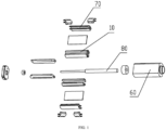
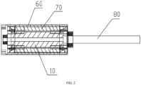
- a drive motor includes the housing 60 and the stator iron core 70 arranged inside the housing 60.
- a rotor iron core is placed through the inside of the stator iron core 70.
- the rotor iron core includes the cylindrical iron core body 10, and two grooves 20 are symmetrically formed on a periphery of the iron core body 10 in a radial direction of the iron core body 10.
- the groove 20 has a trapezoidal shape gradually narrowing toward the through hole 50, so that it is convenient to manually or automatically take the iron core and mount the iron core into the motor.
- the iron core body 10 is provided with a plurality of mounting slots 30.
- the mounting slots 30 are rectangular and configured to receive rectangular magnets.
- the magnet should have the same shape as the mounting slot, and the rectangular magnets are readily produced, thereby improving the production speed.
- the mounting slots 30 include two groups of mounting slots, and the two groups of mounting slots 30 are provided on the upper side and the lower side of the two grooves 20, respectively.
- Each group of mounting slots 30 include two mounting slots, and the two mounting slots 30 in the same group are symmetrically arranged with respect to the radial direction of the iron core body 10, which are reasonably distributed to reduce the space occupied.
- the symmetry line of the two mounting slots 30 in the same group coincides with the symmetry line of the two grooves 20. This reasonable structure design further reduces the size of the iron core.
Landscapes
- Engineering & Computer Science (AREA)
- Power Engineering (AREA)
- Iron Core Of Rotating Electric Machines (AREA)
- Permanent Field Magnets Of Synchronous Machinery (AREA)
Description
- The present invention relates to the technical field of motors, in particular to a drive motor.
- A motor is an electromagnetic device designed to convert or transmit electric energy according to the law of electromagnetic induction, as well as a drive mechanism. Motors are widely used in vehicles and household appliances such as electric toothbrushes, hair dryers and the like.
- The motor iron core includes a stator iron core and a rotor iron core. The motor iron core plays a pivotal role in the entire motor and functions to increase the magnetic flux of the inductive coil to achieve the maximum conversion of electromagnetic power. Prior rotor iron core structures, however, have the following shortcomings.
- (1) A traditional motor iron core has a complicated and bulky structure, which increases the size of the entire motor and increases the space occupied by the motor.
- (2) The method of assembling the iron core and magnets is laborious and inconvenient, which greatly impedes the installation and use of the magnet.
- In view of the above-mentioned problems, it is highly desirable to improve the existing motor structure, simplify the iron core structure, and reduce the size of the iron core, thereby reducing the space occupied by the motor while facilitating the installation and use of the magnet.
JP H10 174323 A JP H07 236295 A CN204349706U discloses a generator having a power of 6 kW. The generator comprises a motor housing, a stator, and a rotor. The rotor comprises a rotor shaft, a rotor core and a permanent magnet. The rotor core is composed of a plurality of overlapping punching sheets, and an axial hole matching the rotor shaft is provided in the middle of the punching sheet. The punching sheet is also provided with two groups of rectangular permanent magnet mounting holes arranged axially symmetrically, and each group of permanent magnet mounting holes includes two permanent magnet mounting holes arranged in an eight-shaped shape, and a connecting groove is provided between the two closest rectangular corners of the two permanent magnet mounting holes in each group, and the permanent magnet is inserted into the permanent magnet mounting hole.JPS5282804U WO2017/152660A1 discloses an internal heat dissipation salient pole rotor comprising a laminated stamped sheet iron core, a magnetic tile, a rotor mandrel, a baffle, a fan, a flexible shaft circlip, and a bearing. The laminated stamped sheet iron core is formed by stamped sheets being laminated and fixed together. Openings are provided symmetrically at the outer circular edge of the stamped sheets. Arc-shaped grooves are provided on the outer circumference of the stamped sheets. The center of the circle in which the grooves are provided is alternately arranged with the center of the stamped sheets. Four inner ventilation channels are evenly distributed between the grooves and an inner ring of the stamped sheets. Vents fitting the inner ventilation channels are provided on the baffle. The fan is connected to the bottom of the rotor mandrel. The bearing is connected to the top of the rotor mandrel. The weight of the rotor is reduced by the openings symmetrically provided on the outer circular edge of the stamped sheets, and the high temperature brought forth by high speed rotation of the rotor is reduced by the inner ventilation channels provided on the stamped sheets and the vents used in tandem with the fan, thus preventing a motor from burning. The center of the circle in which the arc-shaped grooves for mounting the magnetic tile are provided is alternately arranged with the center of the stamped sheets, air gaps are provided evenly and reasonably.CN105406621A discloses a rotor punching sheet with a hidden pole structure for a small-power rare earth permanent magnet generator. The rotor punching sheet comprises a sheet body, wherein a circular hole matching with a rotor core is provided in the middle of the sheet body, and two symmetrically distributed sector-shaped notches with a central angle of 56 degrees are provided on the sheet body, two symmetrically distributed sector-shaped sheet bodies are formed between the two sector-shaped notches, and each sector-shaped sheet body is evenly distributed with two sector-shaped magnetic tile mounting holes with a central angle of 60 degrees.JP2004260988A - The present invention aims to solve the technical problem that the existing motor iron core has a complicated structure and a large size, which increases the space occupied by the motor and is not conducive to the installation of the magnet.
- To solve the above-mentioned technical problems,the present invention provides a drive motor as defined in claim 1. The drive motor includes a housing and a stator iron core. The stator iron core is arranged inside the housing. A rotor iron core having two-poles is placed through the inside of the stator iron core. The rotor iron core includes a cylindrical iron core body. The cylindrical iron core body is provided with a plurality of mounting slots with magnets inserted therein.
- The plurality of mounting slots include two groups of mounting slots, and the two groups of mounting slots are provided on an upper side and a lower side of the cylindrical iron core body, which are corresponding to the two-poles respectively. Each group of the two groups of mounting slots include two mounting slots, and the two mounting slots in the each group are symmetrically arranged each other with respect to a radial symmetry line of the cylindrical iron core body wherein the symmetry line is a d-axis of the rotor. A central part of the cylindrical iron core body is provided with a through hole, wherein a rotating shaft is inserted into the through hole.
- Two grooves having a trapezoidal shape gradually narrowing toward the through hole and extending fully along the axial direction of the cylindrical iron core body are symmetrically formed at both end sides of a radial axis of the rotor, respectively, on a periphery of the cylindrical iron core body with respect to a symmetry line of the two grooves, wherein the radial axis of the rotor is perpendicular to the d-axis of the rotor. The symmetry line of the two mounting slots in the each group coincides with the symmetry line of the two grooves. Each mounting slot of the plurality of mounting slots is rectangular, wherein each magnet has the same shape as the corresponding mounting slot; the plurality of mounting slots are arranged along a circumferential direction of the rotor iron core. Each of both sides of the each mounting slot is provided with a magnetic-leakproof air slot; and the magnetic-leakproof air slot is void closed within the cylindrical iron core body in a cross-section perpendicular to an axial direction of the cylindrical iron core body; a partition is provided between the two mounting slots in the same group; and the shape of each magnetic-leakproof air slot at the most distant ends of the mounting slots in the same group is an arc, and a shape of the magnetic-leakproof air slots at the closest ends of the two mounting slots in the same group is a combination of an arc and a straight line, such that each partition has a radially inner rectangular portion longitudinally extending along the d-axis, radially outwards from the two adjacent radially inner corners of the mounting slots in the same group, and a radially outer portion extending from the rectangular portion in an arc-shaped manner towards the two adjacent radially outer corners of the mounting slots in the same group.
- Preferably, the stator iron core consists of two symmetrical pieces; each of the two symmetrical pieces includes a first iron core connected to the housing and a second iron core arranged inside the first iron core; the first iron core and the second iron core are connected by a core column, and a slot for winding a coil is enclosed by the first iron core, the second iron core and both sides of the core column; Alternatively, both sides of the two first iron cores are connected by an iron core baffle; both ends of the iron core baffle and the two first iron cores are detachably arranged; the two sides of the first iron core are provided with limiting slots, and limiting plates protrude from two sides of the iron core baffle.
- Preferably, the each mounting slots is arranged adjacent to the edge of the rotor iron core.
- Compared with the prior art, the present invention simplifies the structure of the iron core body and reduces its size, thereby reducing the space occupied by the motor. The iron core body adopts an embedded type, having a simple and compact structure. Thus, it is easy to mount the iron core on a motor. Moreover, the magnets are mounted in the mounting slots by means of insertion, which is quick and convenient to operate. Each of both sides of the mounting slot is provided with a magnetic-leakproof air slot to prevent the leakage of the electromagnetic force of the magnet, so that the electromagnetic force of the magnet can be effectively utilized to improve the performance of the motor.
-
-
FIG. 1 is an exploded view of the present invention; -
FIG. 2 is a cross-sectional view of the present invention; -
FIG. 3 is a structural schematic view of the rotor iron core of the present invention (not constituting a part of the present invention); and -
FIG. 4 is a side view of the rotor iron core of the present invention. - The present invention provides a drive motor, the structure of the iron core body is simplified and its size is reduced, thereby reducing the space occupied by the motor. The iron core body has a simple and compact structure and is easily mounted on the motor. Moreover, the magnets are mounted in the mounting slots by means of insertion, which is quick and convenient to operate. The present invention will be described in detail below with reference to the drawings and specific implementations of the specification.
- As shown in
FIGS. 1-4 , a drive motor includes thehousing 60 and thestator iron core 70 arranged inside thehousing 60. A rotor iron core is placed through the inside of thestator iron core 70. The rotor iron core includes the cylindricaliron core body 10, and twogrooves 20 are symmetrically formed on a periphery of theiron core body 10 in a radial direction of theiron core body 10. Thegroove 20 has a trapezoidal shape gradually narrowing toward the throughhole 50, so that it is convenient to manually or automatically take the iron core and mount the iron core into the motor. - As shown in
FIGS. 3-4 , theiron core body 10 is provided with a plurality of mountingslots 30. The mountingslots 30 are rectangular and configured to receive rectangular magnets. Correspondingly, the magnet should have the same shape as the mounting slot, and the rectangular magnets are readily produced, thereby improving the production speed. The mountingslots 30 include two groups of mounting slots, and the two groups of mountingslots 30 are provided on the upper side and the lower side of the twogrooves 20, respectively. Each group of mountingslots 30 include two mounting slots, and the two mountingslots 30 in the same group are symmetrically arranged with respect to the radial direction of theiron core body 10, which are reasonably distributed to reduce the space occupied. - The symmetry line of the two mounting
slots 30 in the same group coincides with the symmetry line of the twogrooves 20. This reasonable structure design further reduces the size of the iron core. - Further, since the magnetic field strength of the magnet gradually decreases toward the direction away from the magnet, each mounting
slot 30 is preferably arranged adjacent to the edge of the rotor iron core, so that thestator iron core 70 is adjacent to the magnet. In this way, the electromagnetic force of the magnet can be effectively utilized to improve the performance of the motor. - The mounting slots are arranged along the circumferential direction of the rotor iron core, which conforms to the characteristics of the magnetic field distribution, and increases the area of the
stator iron core 70 cutting the magnetic field lines, thereby improving the performance of the iron core. Moreover, the size of the iron core is effectively reduced compared to the horizontal arrangement. - A partition is arranged between the two mounting
slots 30 in the same group, and preferably, the partition is supported on a top leg of the magnet, so that the magnet is fixed more firmly and is prevented from shaking. - In the present invention, each of both sides of the mounting
slot 30 is provided with the magnetic-leakproof air slot 40 to facilitate the insertion of the magnet into the mountingslot 30, and prevent the electromagnetic force of the magnet from leaking, so that the electromagnetic force of the magnet can be can effectively utilized to improve the performance of the motor. - The central part of the
iron core body 10 is provided with the throughhole 50 into which therotating shaft 80 of the motor is inserted, and then therotating shaft 80 is driven to rotate by the rotation of theiron core body 10. - The
stator iron core 70 is arranged in multiple manners. For example, thestator iron core 70 includes a first iron core connected to thehousing 60 and a second iron core arranged inside the first iron core. The first iron core and the second iron core are connected by a core column, and a slot for winding a coil is enclosed by the first iron core, the second iron core and both sides of the core column. - Alternatively, both sides of the two first iron cores are connected by an iron core baffle. Both ends of the iron core baffle and the two first iron cores are detachably arranged. The two sides of the first iron core are provided with limiting slots, and limiting plates protrude from two sides of the iron core baffle. In this arrangement, the iron core can realize fly-fork winding, and the iron core is welded to the iron core baffle after a coil is wound, which increases the efficiency of assembling the drive motor. Additionally, the coil can be filled in the slot to increase the fill factor of the slot, thereby improving the performance of the motor.
- The
iron core body 10 of the present invention is placed in the space enclosed by two second iron cores, which reduces the size of the drive motor and makes the motor more compact and lightweight. - The present invention simplifies the structure of the iron core body and reduces its size, thereby reducing the space occupied by the motor. The iron core body adopts an embedded type, having a simple and compact structure, and is easily mounted on a motor. Moreover, the magnets are mounted in the mounting slots by means of insertion, which is quick and convenient to operate. Each of both sides of the mounting slot is provided with a magnetic-leakproof air slot to prevent the leakage of the electromagnetic force of the magnet, so that the electromagnetic force of the magnet can be effectively utilized to improve the performance of the motor.
Claims (3)
- A drive motor, comprisinga housing (60), anda stator iron core (70);whereinthe stator iron core is arranged inside the housing;a rotor iron core having two-poles is placed through an inside of the stator iron core;the rotor iron core comprises a cylindrical iron core body (10) and the cylindrical iron core body is provided with a plurality of mounting slots (30) with magnets inserted therein, wherein the plurality of mounting slots comprise two groups of mounting slots, and the two groups of mounting slots are provided on an upper side and a lower side of the cylindrical iron core body, which are corresponding to the two-poles respectively; each group of the two groups of mounting slots comprise two mounting slots, and the two mounting slots in the each group are symmetrically arranged each other with respect to a radial symmetry line of the cylindrical iron core body wherein the symmetry line is a d-axis of the rotor;a central part of the cylindrical iron core body is provided with a through hole (50), wherein a rotating shaft (80) is inserted into the through hole;two grooves (20) having a trapezoidal shape gradually narrowing toward the through hole and extending fully along the axial direction of the cylindrical iron core body are symmetrically formed at both end sides of a radial axis of the rotor, respectively, on a periphery of the cylindrical iron core body with respect to a symmetry line of the two grooves, wherein the radial axis of the rotor is perpendicular to the d-axis of the rotor and, the symmetry line of the two mounting slots in the each group coincides with the symmetry line of the two grooves;each mounting slot of the plurality of mounting slots is rectangular, wherein each magnet has the same shape as the corresponding mounting slot; the plurality of mounting slots are arranged along a circumferential direction of the rotor iron core; andeach of both sides of the each mounting slot is provided with a magnetic-leakproof air slot (40); and the magnetic-leakproof air slot (40) is void closed within the cylindrical iron core body (10) in a cross-section perpendicular to an axial direction of the cylindrical iron core body;a partition is provided between the two mounting slots in the same group;and the shape of each magnetic-leakproof air slot at the most distant ends of the mounting slots in the same group is an arc, anda shape of the magnetic-leakproof air slots at the closest ends of the two mounting slots in the same group is a combination of an arc and a straight line,such that each partition has a radially inner rectangular portion longitudinally extending along the d-axis, radially outwards from the two adjacent radially inner corners of the mounting slots in the same group,and a radially outer portion extending from the rectangular portion in an arc-shaped manner towards the two adjacent radially outer corners of the mounting slots in the same group.
- The drive motor according to claim 1, wherein,
the stator iron core (70) consists of two symmetrical pieces; each of the two symmetrical pieces includes a first iron core connected to the housing (60) and a second iron core arranged inside the first iron core; the first iron core and the second iron core are connected by a core column, and a slot for winding a coil is enclosed by the first iron core, the second iron core and both sides of the core column; or both sides of the two first iron cores are connected by an iron core baffle; both ends of the iron core baffle and the two first iron cores are detachably arranged; the two sides of the first iron core are provided with limiting slots, and limiting plates protrude from two sides of the iron core baffle. - The drive motor according to claim 1, wherein,
the each mounting slot is arranged adjacent to an edge of the rotor iron core.
Applications Claiming Priority (3)
| Application Number | Priority Date | Filing Date | Title |
|---|---|---|---|
| CN201820899338 | 2018-06-11 | ||
| CN201810896858.9A CN108808918A (en) | 2018-06-11 | 2018-08-08 | A kind of drive motor |
| PCT/CN2019/071897 WO2019237736A1 (en) | 2018-06-11 | 2019-01-16 | Driving motor |
Publications (4)
| Publication Number | Publication Date |
|---|---|
| EP3806288A1 EP3806288A1 (en) | 2021-04-14 |
| EP3806288A4 EP3806288A4 (en) | 2021-08-11 |
| EP3806288B1 true EP3806288B1 (en) | 2025-07-02 |
| EP3806288C0 EP3806288C0 (en) | 2025-07-02 |
Family
ID=64079634
Family Applications (1)
| Application Number | Title | Priority Date | Filing Date |
|---|---|---|---|
| EP19819686.7A Active EP3806288B1 (en) | 2018-06-11 | 2019-01-16 | Driving motor |
Country Status (5)
| Country | Link |
|---|---|
| US (1) | US11967865B2 (en) |
| EP (1) | EP3806288B1 (en) |
| CN (2) | CN208589826U (en) |
| HU (1) | HUE072672T2 (en) |
| WO (1) | WO2019237736A1 (en) |
Families Citing this family (1)
| Publication number | Priority date | Publication date | Assignee | Title |
|---|---|---|---|---|
| CN208589826U (en) * | 2018-06-11 | 2019-03-08 | 宝龙电子集团有限公司 | A kind of drive motor |
Citations (5)
| Publication number | Priority date | Publication date | Assignee | Title |
|---|---|---|---|---|
| JPS5282804U (en) * | 1975-12-19 | 1977-06-21 | ||
| JP2004260988A (en) * | 2003-02-27 | 2004-09-16 | Lg Electronics Inc | Stator assembly of motor and its producing process |
| CN204349706U (en) * | 2014-12-10 | 2015-05-20 | 重庆智仁发电设备有限责任公司 | A kind of 6kW generator |
| CN105406621A (en) * | 2015-12-04 | 2016-03-16 | 重庆智仁发电设备有限责任公司 | Small-power rare earth permanent magnet generator non-salient pole type structural rotor punching sheet |
| WO2017152660A1 (en) * | 2016-03-10 | 2017-09-14 | 重庆智仁发电设备有限责任公司 | Internal heat dissipation salient pole rotor |
Family Cites Families (23)
| Publication number | Priority date | Publication date | Assignee | Title |
|---|---|---|---|---|
| JPH07236295A (en) | 1994-02-23 | 1995-09-05 | Yaskawa Electric Corp | Drive control method for inner magnet type brushless DC motor |
| JPH10174323A (en) * | 1996-12-16 | 1998-06-26 | Yaskawa Electric Corp | Inner magnet type motor rotor |
| TW364234B (en) * | 1997-04-14 | 1999-07-11 | Sanyo Electric Co | Rotor for an electric motor |
| JPH11332144A (en) * | 1998-05-15 | 1999-11-30 | Toyo Electric Mfg Co Ltd | 2-pole permanent magnet rotor |
| DE19933009A1 (en) * | 1998-07-24 | 2000-02-10 | Matsushita Electric Industrial Co Ltd | Electric motor e.g. for automobile air conditioning unit, has rotor core provided with slits for reception of internal permanent magnets with non-magnetic section between each permanent magnet and rotor periphery |
| DE60212406T2 (en) * | 2002-11-15 | 2007-02-01 | Minebea Co., Ltd. | Runners with embedded permanent magnets |
| JP2004270544A (en) * | 2003-03-07 | 2004-09-30 | Matsushita Electric Ind Co Ltd | Magnetizing jig, electric compressor, method of assembling rotor, and method of assembling electric compressor |
| DE102006055519A1 (en) * | 2006-11-24 | 2008-05-29 | Robert Bosch Gmbh | Stator for an electric machine |
| US8405270B2 (en) * | 2007-05-07 | 2013-03-26 | Panasonic Corporation | Permanent magnet buried type electric motor |
| JP5433198B2 (en) * | 2008-10-16 | 2014-03-05 | 日立オートモティブシステムズ株式会社 | Rotating electric machines and electric vehicles |
| KR101867973B1 (en) * | 2011-07-22 | 2018-06-18 | 엘지이노텍 주식회사 | Rotor of Motor and motor having the same |
| US9490673B2 (en) * | 2012-08-16 | 2016-11-08 | Mitsuba Corporation | Rotor of magnet-assisted reluctance motor and brushless motor |
| US9893575B2 (en) * | 2013-03-25 | 2018-02-13 | Panasonic Intellectual Property Management Co., Ltd. | Permanent-magnet-embedded electric motor and method for manufacturing same |
| JP6257212B2 (en) * | 2013-08-05 | 2018-01-10 | 株式会社ミツバ | Brushless motor |
| CN103956872B (en) * | 2014-04-25 | 2018-07-20 | 联合汽车电子有限公司 | Permanent magnet synchronous motor and its rotor |
| JP2016010176A (en) * | 2014-06-20 | 2016-01-18 | 日本電産株式会社 | Motor |
| US9793783B2 (en) * | 2014-06-27 | 2017-10-17 | Toyota Jidosha Kabushiki Kaisha | Rotor of rotary electric machine |
| CN104539072A (en) * | 2014-12-10 | 2015-04-22 | 重庆智仁发电设备有限责任公司 | Power generating device |
| CN204334267U (en) * | 2014-12-27 | 2015-05-13 | 无锡新启源电机技术有限公司 | The punching of splayed two groove Rare-earth PMSM Rotor Structure |
| CN105576867B (en) | 2016-02-17 | 2019-03-22 | 珠海格力节能环保制冷技术研究中心有限公司 | A kind of permanent magnet machine rotor and magneto |
| KR102683823B1 (en) * | 2016-08-17 | 2024-07-10 | 현대모비스 주식회사 | motor rotor with support for retaining rigidity and preventing separation of magnet |
| CN106230215B (en) * | 2016-09-05 | 2019-02-05 | 珠海凌达压缩机有限公司 | Motor and rotor structure thereof |
| CN208589826U (en) * | 2018-06-11 | 2019-03-08 | 宝龙电子集团有限公司 | A kind of drive motor |
-
2018
- 2018-08-08 CN CN201821276578.XU patent/CN208589826U/en active Active
- 2018-08-08 CN CN201810896858.9A patent/CN108808918A/en active Pending
-
2019
- 2019-01-16 HU HUE19819686A patent/HUE072672T2/en unknown
- 2019-01-16 EP EP19819686.7A patent/EP3806288B1/en active Active
- 2019-01-16 US US17/251,217 patent/US11967865B2/en active Active
- 2019-01-16 WO PCT/CN2019/071897 patent/WO2019237736A1/en not_active Ceased
Patent Citations (5)
| Publication number | Priority date | Publication date | Assignee | Title |
|---|---|---|---|---|
| JPS5282804U (en) * | 1975-12-19 | 1977-06-21 | ||
| JP2004260988A (en) * | 2003-02-27 | 2004-09-16 | Lg Electronics Inc | Stator assembly of motor and its producing process |
| CN204349706U (en) * | 2014-12-10 | 2015-05-20 | 重庆智仁发电设备有限责任公司 | A kind of 6kW generator |
| CN105406621A (en) * | 2015-12-04 | 2016-03-16 | 重庆智仁发电设备有限责任公司 | Small-power rare earth permanent magnet generator non-salient pole type structural rotor punching sheet |
| WO2017152660A1 (en) * | 2016-03-10 | 2017-09-14 | 重庆智仁发电设备有限责任公司 | Internal heat dissipation salient pole rotor |
Also Published As
| Publication number | Publication date |
|---|---|
| HUE072672T2 (en) | 2025-12-28 |
| CN208589826U (en) | 2019-03-08 |
| EP3806288A1 (en) | 2021-04-14 |
| US11967865B2 (en) | 2024-04-23 |
| US20210249918A1 (en) | 2021-08-12 |
| EP3806288A4 (en) | 2021-08-11 |
| EP3806288C0 (en) | 2025-07-02 |
| CN108808918A (en) | 2018-11-13 |
| WO2019237736A1 (en) | 2019-12-19 |
Similar Documents
| Publication | Publication Date | Title |
|---|---|---|
| CN105245073B (en) | Stator permanent magnetic type double-salient-pole disc type electric machine | |
| RU2557556C2 (en) | Squirrel-cage rotor | |
| JPH0720360B2 (en) | Dynamo Electric Machine and Stator Assembly | |
| WO2016058446A1 (en) | Motor | |
| JP2000156947A (en) | Magnet-type motor and power generator | |
| JP2015516139A (en) | Multi-phase permanent magnet motor with adjustable leakage inductance | |
| EP3062426A1 (en) | Single-phase brushless motor | |
| CN113629903A (en) | A high-speed permanent magnet motor | |
| CN114337164A (en) | Method for reducing torque pulsation of permanent magnet double-rotor motor | |
| CN105119454A (en) | Halbach array permanent magnet DC brushless motor | |
| CN204858923U (en) | A directly drive formula permanent magnetism AC servo motor for forging press | |
| US11336163B2 (en) | Low profile axial, flux permanent magnet synchronous motor | |
| JPH1094230A (en) | Abduction type concentrated winding rotating electric machine and electric vehicle using it | |
| EP3574570B1 (en) | Modular stators and rotors for axial flux electric machines and methods of assembly | |
| CN116260302B (en) | A permanent magnet synchronous motor with axial-transverse mixed flux | |
| EP3602757B1 (en) | Brushless motor | |
| CN106655556B (en) | Circumferential winding power motor and new energy electric vehicle | |
| US12451788B2 (en) | Magnetic geared rotating machine and power generation system | |
| CN108288881A (en) | A permanent magnet motor | |
| CN112039239A (en) | Rotor pressing plate for permanent magnet synchronous motor and permanent magnet synchronous motor | |
| US20230042319A1 (en) | Electrical machine including axial flux rotor and coreless stator | |
| CN210350986U (en) | A dual-rotor permanent magnet synchronous reluctance motor | |
| CN112671137A (en) | Brushless motor | |
| CN203537091U (en) | Double-salient pole double-squirrel cage outer rotor structure of stator permanent magnet double-rotor motor | |
| CN207732599U (en) | Asynchronous motor based on pulsating field |
Legal Events
| Date | Code | Title | Description |
|---|---|---|---|
| STAA | Information on the status of an ep patent application or granted ep patent |
Free format text: STATUS: THE INTERNATIONAL PUBLICATION HAS BEEN MADE |
|
| PUAI | Public reference made under article 153(3) epc to a published international application that has entered the european phase |
Free format text: ORIGINAL CODE: 0009012 |
|
| STAA | Information on the status of an ep patent application or granted ep patent |
Free format text: STATUS: REQUEST FOR EXAMINATION WAS MADE |
|
| 17P | Request for examination filed |
Effective date: 20210111 |
|
| AK | Designated contracting states |
Kind code of ref document: A1 Designated state(s): AL AT BE BG CH CY CZ DE DK EE ES FI FR GB GR HR HU IE IS IT LI LT LU LV MC MK MT NL NO PL PT RO RS SE SI SK SM TR |
|
| AX | Request for extension of the european patent |
Extension state: BA ME |
|
| REG | Reference to a national code |
Ref country code: DE Ref legal event code: R079 Free format text: PREVIOUS MAIN CLASS: H02K0001220000 Ipc: H02K0001270000 Ref document number: 602019072031 Country of ref document: DE |
|
| A4 | Supplementary search report drawn up and despatched |
Effective date: 20210708 |
|
| RIC1 | Information provided on ipc code assigned before grant |
Ipc: H02K 1/27 20060101AFI20210702BHEP Ipc: H02K 21/14 20060101ALI20210702BHEP |
|
| DAV | Request for validation of the european patent (deleted) | ||
| DAX | Request for extension of the european patent (deleted) | ||
| RAP1 | Party data changed (applicant data changed or rights of an application transferred) |
Owner name: SHENZHEN YUNDING INFORMATION TECHNOLOGY CO., LTD. Owner name: ZHEJIANG BAOLONG M&E CO., LTD. |
|
| STAA | Information on the status of an ep patent application or granted ep patent |
Free format text: STATUS: EXAMINATION IS IN PROGRESS |
|
| 17Q | First examination report despatched |
Effective date: 20220315 |
|
| REG | Reference to a national code |
Ref country code: DE Ref legal event code: R079 Free format text: PREVIOUS MAIN CLASS: H02K0001270000 Ipc: H02K0001276000 Ref country code: DE Ref legal event code: R079 Ref document number: 602019072031 Country of ref document: DE Free format text: PREVIOUS MAIN CLASS: H02K0001270000 Ipc: H02K0001276000 |
|
| GRAP | Despatch of communication of intention to grant a patent |
Free format text: ORIGINAL CODE: EPIDOSNIGR1 |
|
| STAA | Information on the status of an ep patent application or granted ep patent |
Free format text: STATUS: GRANT OF PATENT IS INTENDED |
|
| RIC1 | Information provided on ipc code assigned before grant |
Ipc: H02K 21/14 20060101ALI20250205BHEP Ipc: H02K 1/276 20220101AFI20250205BHEP |
|
| INTG | Intention to grant announced |
Effective date: 20250225 |
|
| GRAS | Grant fee paid |
Free format text: ORIGINAL CODE: EPIDOSNIGR3 |
|
| GRAA | (expected) grant |
Free format text: ORIGINAL CODE: 0009210 |
|
| STAA | Information on the status of an ep patent application or granted ep patent |
Free format text: STATUS: THE PATENT HAS BEEN GRANTED |
|
| RIN1 | Information on inventor provided before grant (corrected) |
Inventor name: LIN, FANGKUI Inventor name: LI, JUN Inventor name: GUO, ZHIYAN |
|
| AK | Designated contracting states |
Kind code of ref document: B1 Designated state(s): AL AT BE BG CH CY CZ DE DK EE ES FI FR GB GR HR HU IE IS IT LI LT LU LV MC MK MT NL NO PL PT RO RS SE SI SK SM TR |
|
| REG | Reference to a national code |
Ref country code: GB Ref legal event code: FG4D |
|
| REG | Reference to a national code |
Ref country code: CH Ref legal event code: EP |
|
| REG | Reference to a national code |
Ref country code: DE Ref legal event code: R096 Ref document number: 602019072031 Country of ref document: DE |
|
| REG | Reference to a national code |
Ref country code: IE Ref legal event code: FG4D |
|
| U01 | Request for unitary effect filed |
Effective date: 20250718 |
|
| U07 | Unitary effect registered |
Designated state(s): AT BE BG DE DK EE FI FR IT LT LU LV MT NL PT RO SE SI Effective date: 20250725 |
|
| REG | Reference to a national code |
Ref country code: HU Ref legal event code: AG4A Ref document number: E072672 Country of ref document: HU |
|
| PG25 | Lapsed in a contracting state [announced via postgrant information from national office to epo] |
Ref country code: IS Free format text: LAPSE BECAUSE OF FAILURE TO SUBMIT A TRANSLATION OF THE DESCRIPTION OR TO PAY THE FEE WITHIN THE PRESCRIBED TIME-LIMIT Effective date: 20251102 |
|
| PGFP | Annual fee paid to national office [announced via postgrant information from national office to epo] |
Ref country code: GB Payment date: 20251222 Year of fee payment: 8 |
|
| PG25 | Lapsed in a contracting state [announced via postgrant information from national office to epo] |
Ref country code: NO Free format text: LAPSE BECAUSE OF FAILURE TO SUBMIT A TRANSLATION OF THE DESCRIPTION OR TO PAY THE FEE WITHIN THE PRESCRIBED TIME-LIMIT Effective date: 20251002 |
|
| PG25 | Lapsed in a contracting state [announced via postgrant information from national office to epo] |
Ref country code: HR Free format text: LAPSE BECAUSE OF FAILURE TO SUBMIT A TRANSLATION OF THE DESCRIPTION OR TO PAY THE FEE WITHIN THE PRESCRIBED TIME-LIMIT Effective date: 20250702 |
|
| PG25 | Lapsed in a contracting state [announced via postgrant information from national office to epo] |
Ref country code: GR Free format text: LAPSE BECAUSE OF FAILURE TO SUBMIT A TRANSLATION OF THE DESCRIPTION OR TO PAY THE FEE WITHIN THE PRESCRIBED TIME-LIMIT Effective date: 20251003 |
|
| PG25 | Lapsed in a contracting state [announced via postgrant information from national office to epo] |
Ref country code: CZ Free format text: LAPSE BECAUSE OF FAILURE TO SUBMIT A TRANSLATION OF THE DESCRIPTION OR TO PAY THE FEE WITHIN THE PRESCRIBED TIME-LIMIT Effective date: 20250702 |
|
| PG25 | Lapsed in a contracting state [announced via postgrant information from national office to epo] |
Ref country code: PL Free format text: LAPSE BECAUSE OF FAILURE TO SUBMIT A TRANSLATION OF THE DESCRIPTION OR TO PAY THE FEE WITHIN THE PRESCRIBED TIME-LIMIT Effective date: 20250702 |
|
| PG25 | Lapsed in a contracting state [announced via postgrant information from national office to epo] |
Ref country code: RS Free format text: LAPSE BECAUSE OF FAILURE TO SUBMIT A TRANSLATION OF THE DESCRIPTION OR TO PAY THE FEE WITHIN THE PRESCRIBED TIME-LIMIT Effective date: 20251002 |
|
| U20 | Renewal fee for the european patent with unitary effect paid |
Year of fee payment: 8 Effective date: 20251222 |
|
| PG25 | Lapsed in a contracting state [announced via postgrant information from national office to epo] |
Ref country code: ES Free format text: LAPSE BECAUSE OF FAILURE TO SUBMIT A TRANSLATION OF THE DESCRIPTION OR TO PAY THE FEE WITHIN THE PRESCRIBED TIME-LIMIT Effective date: 20250702 |
|
| REG | Reference to a national code |
Ref country code: CH Ref legal event code: U11 Free format text: ST27 STATUS EVENT CODE: U-0-0-U10-U11 (AS PROVIDED BY THE NATIONAL OFFICE) Effective date: 20260201 |
|
| PGFP | Annual fee paid to national office [announced via postgrant information from national office to epo] |
Ref country code: HU Payment date: 20251229 Year of fee payment: 8 |
|
| PG25 | Lapsed in a contracting state [announced via postgrant information from national office to epo] |
Ref country code: SM Free format text: LAPSE BECAUSE OF FAILURE TO SUBMIT A TRANSLATION OF THE DESCRIPTION OR TO PAY THE FEE WITHIN THE PRESCRIBED TIME-LIMIT Effective date: 20250702 |
|
| PGFP | Annual fee paid to national office [announced via postgrant information from national office to epo] |
Ref country code: CH Payment date: 20260201 Year of fee payment: 8 |
|
| PG25 | Lapsed in a contracting state [announced via postgrant information from national office to epo] |
Ref country code: SK Free format text: LAPSE BECAUSE OF FAILURE TO SUBMIT A TRANSLATION OF THE DESCRIPTION OR TO PAY THE FEE WITHIN THE PRESCRIBED TIME-LIMIT Effective date: 20250702 |
|
| PLBE | No opposition filed within time limit |
Free format text: ORIGINAL CODE: 0009261 |
|
| STAA | Information on the status of an ep patent application or granted ep patent |
Free format text: STATUS: NO OPPOSITION FILED WITHIN TIME LIMIT |