EP3806262A1 - Control device and power conversion device - Google Patents
Control device and power conversion device Download PDFInfo
- Publication number
- EP3806262A1 EP3806262A1 EP18920935.6A EP18920935A EP3806262A1 EP 3806262 A1 EP3806262 A1 EP 3806262A1 EP 18920935 A EP18920935 A EP 18920935A EP 3806262 A1 EP3806262 A1 EP 3806262A1
- Authority
- EP
- European Patent Office
- Prior art keywords
- direct current
- current voltage
- arithmetic unit
- voltage
- control device
- Prior art date
- Legal status (The legal status is an assumption and is not a legal conclusion. Google has not performed a legal analysis and makes no representation as to the accuracy of the status listed.)
- Pending
Links
Images



Classifications
-
- H—ELECTRICITY
- H02—GENERATION; CONVERSION OR DISTRIBUTION OF ELECTRIC POWER
- H02J—ELECTRIC POWER NETWORKS; CIRCUIT ARRANGEMENTS OR SYSTEMS FOR SUPPLYING OR DISTRIBUTING ELECTRIC POWER; SYSTEMS FOR STORING ELECTRIC ENERGY
- H02J1/00—Circuit arrangements for DC mains or DC distribution networks
-
- H—ELECTRICITY
- H02—GENERATION; CONVERSION OR DISTRIBUTION OF ELECTRIC POWER
- H02J—ELECTRIC POWER NETWORKS; CIRCUIT ARRANGEMENTS OR SYSTEMS FOR SUPPLYING OR DISTRIBUTING ELECTRIC POWER; SYSTEMS FOR STORING ELECTRIC ENERGY
- H02J13/00—Circuit arrangements for providing remote monitoring or remote control of equipment in a power distribution network
- H02J13/13—Circuit arrangements for providing remote monitoring or remote control of equipment in a power distribution network characterised by the transmission of data to equipment in the power network
-
- H—ELECTRICITY
- H02—GENERATION; CONVERSION OR DISTRIBUTION OF ELECTRIC POWER
- H02J—ELECTRIC POWER NETWORKS; CIRCUIT ARRANGEMENTS OR SYSTEMS FOR SUPPLYING OR DISTRIBUTING ELECTRIC POWER; SYSTEMS FOR STORING ELECTRIC ENERGY
- H02J3/00—Circuit arrangements for AC mains or AC distribution networks
- H02J3/36—Arrangements for transfer of electric power between AC networks via high-voltage DC [HVDC] links; Arrangements for transfer of electric power between generators and networks via HVDC links
-
- Y—GENERAL TAGGING OF NEW TECHNOLOGICAL DEVELOPMENTS; GENERAL TAGGING OF CROSS-SECTIONAL TECHNOLOGIES SPANNING OVER SEVERAL SECTIONS OF THE IPC; TECHNICAL SUBJECTS COVERED BY FORMER USPC CROSS-REFERENCE ART COLLECTIONS [XRACs] AND DIGESTS
- Y02—TECHNOLOGIES OR APPLICATIONS FOR MITIGATION OR ADAPTATION AGAINST CLIMATE CHANGE
- Y02B—CLIMATE CHANGE MITIGATION TECHNOLOGIES RELATED TO BUILDINGS, e.g. HOUSING, HOUSE APPLIANCES OR RELATED END-USER APPLICATIONS
- Y02B90/00—Enabling technologies or technologies with a potential or indirect contribution to GHG emissions mitigation
- Y02B90/20—Smart grids as enabling technology in buildings sector
-
- Y—GENERAL TAGGING OF NEW TECHNOLOGICAL DEVELOPMENTS; GENERAL TAGGING OF CROSS-SECTIONAL TECHNOLOGIES SPANNING OVER SEVERAL SECTIONS OF THE IPC; TECHNICAL SUBJECTS COVERED BY FORMER USPC CROSS-REFERENCE ART COLLECTIONS [XRACs] AND DIGESTS
- Y02—TECHNOLOGIES OR APPLICATIONS FOR MITIGATION OR ADAPTATION AGAINST CLIMATE CHANGE
- Y02E—REDUCTION OF GREENHOUSE GAS [GHG] EMISSIONS, RELATED TO ENERGY GENERATION, TRANSMISSION OR DISTRIBUTION
- Y02E60/00—Enabling technologies; Technologies with a potential or indirect contribution to GHG emissions mitigation
- Y02E60/60—Arrangements for transfer of electric power between AC networks or generators via a high voltage DC link [HVCD]
-
- Y—GENERAL TAGGING OF NEW TECHNOLOGICAL DEVELOPMENTS; GENERAL TAGGING OF CROSS-SECTIONAL TECHNOLOGIES SPANNING OVER SEVERAL SECTIONS OF THE IPC; TECHNICAL SUBJECTS COVERED BY FORMER USPC CROSS-REFERENCE ART COLLECTIONS [XRACs] AND DIGESTS
- Y04—INFORMATION OR COMMUNICATION TECHNOLOGIES HAVING AN IMPACT ON OTHER TECHNOLOGY AREAS
- Y04S—SYSTEMS INTEGRATING TECHNOLOGIES RELATED TO POWER NETWORK OPERATION, COMMUNICATION OR INFORMATION TECHNOLOGIES FOR IMPROVING THE ELECTRICAL POWER GENERATION, TRANSMISSION, DISTRIBUTION, MANAGEMENT OR USAGE, i.e. SMART GRIDS
- Y04S40/00—Systems for electrical power generation, transmission, distribution or end-user application management characterised by the use of communication or information technologies, or communication or information technology specific aspects supporting them
- Y04S40/12—Systems for electrical power generation, transmission, distribution or end-user application management characterised by the use of communication or information technologies, or communication or information technology specific aspects supporting them characterised by data transport means between the monitoring, controlling or managing units and monitored, controlled or operated electrical equipment
Definitions
- An embodiment of the invention relates to a control device and a power conversion device.
- the direct current voltage of the opposite end is estimated using an estimated value of the direct current resistance of the power line and the direct current voltage of it's own end without using a high-speed communication line.
- an error is included between the estimated value and the actual direct current voltage value; when the error is large, there is a risk that the operation of the system may be difficult to continue.
- Patent Literature 1 JP-B 3506881
- Embodiments of the invention provide a control device and a power conversion device that are connected to a direct current power transmission system and can be operated without using a high-speed communication line.
- a control device capable of controlling a power converter connected to one terminal of a direct current power transmission system transmitting power by a direct current power line and capable of receiving, via a communication network, data of a direct current voltage actually measured at another terminal of the direct current power transmission system.
- the control device includes a first controller, a second controller, and a drive signal generator.
- the first controller includes a first arithmetic unit generating a first control output based on a voltage drop, a voltage command value, and a first direct current voltage; the voltage drop is with respect to a voltage of the other terminal estimated based on an estimated value of a direct current resistance of the direct current power line; the voltage command value sets a direct current voltage of the other terminal; and the first direct current voltage is a direct current voltage of the one terminal.
- the second controller includes a second arithmetic unit generating a second control output based on the voltage command value and a second direct current voltage, and the second direct current voltage is a direct current voltage actually measured at the other terminal.
- the drive signal generator generates a drive signal of the power converter based on the first and second control outputs.
- a response speed of the second arithmetic unit is set according to a transmission delay time of the communication network.
- a response speed of the first arithmetic unit is set to be faster than the response speed of the second arithmetic unit.
- the response speed of the second arithmetic unit can be set according to the transmission delay time of the communication network, and the response speed of the first arithmetic unit can be set to be faster than the response speed of the second arithmetic unit; therefore, the direct current voltage of the power transmission end can be controlled with high accuracy regardless of a high-speed communication line.
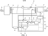
- FIG. 1 is a block diagram illustrating a power conversion device according to the embodiment.
- the direct current power transmission system 1 includes two power conversion devices 10 and 50 and a direct current power line 3.
- the power conversion device 10 is connected between the direct current power line 3 and an alternating current circuit 2b.
- the power conversion device 50 is connected between an alternating current circuit 2a and the direct current power line 3.
- the alternating current circuits 2a and 2b each can have configurations including an alternating current power supply, an alternating current power line, an alternating current load, etc., of 50 Hz or 60 Hz.
- the alternating current circuits 2a and 2b can be different power systems.
- one power conversion device 50 is connected to the power transmission end that transmits direct current power
- the other power conversion device 10 is connected to the power receiving end that receives the direct current power.
- the direct current power transmission system 1 the transmission of bidirectional direct current power is possible, and the terminal to which the power conversion device 50 is connected can be used as the power receiving end; in such a case, the terminal to which the power conversion device 10 is connected can be used as the power transmission end.
- the power conversion devices 10 and 50 have the same configuration, and the configuration of the power conversion device 10 is described below.
- the power conversion device is applicable to a multi-terminal direct current power transmission system including three or more terminals in all of the embodiments.
- the power conversion device 10 includes a power converter 20 and a control device 30.
- the power converter 20 converts the transmitted direct current voltage into an alternating current voltage and outputs the alternating current voltage according to a gate signal vg generated by the control device 30.
- the power converter 20 is, for example, a thyristor valve, and the description hereinbelow is for a thyristor valve.
- the power converter is not limited to a separately-excited converter such as a thyristor valve and may be a self-commutated inverter circuit.
- the control device 30 generates the gate signal vg based on direct current voltages Vds and Vdo and a direct current Id and supplies the generated gate signal vg to the power converter 20.
- the direct current voltage Vds is the actual measured value of the direct current terminal voltage of the power conversion device 10 of the power receiving end.
- the direct current voltage Vds is detected by a direct current voltage detector 5b.
- the direct current voltage Vdo is the actual measured value of the direct current terminal voltage of the power conversion device 50 of the power transmission end.
- the direct current voltage Vdo is detected by a direct current voltage detector 5a.
- the direct current Id is the actual measured value of the current flowing through the direct current power line 3.
- the direct current Id is detected by a direct current detector 6.
- the control device 30 includes an automatic voltage regulator (AVR) 31.
- the control device 30 includes a phase controller 40 connected to the AVR 31, and the phase controller (the drive signal generator) 40 generates the gate signal vg based on a signal ⁇ relating to the control angle of the thyristor from the AVR 31.
- the signal ⁇ has a large value according to the control angle, and in the phase controller 40, generates the gate signal to increase the control angle of the thyristor.
- the AVR 31 includes two controllers 32 and 33. As elaborated below, the controller 32 forms a control loop corresponding to a fast response, and the controller 33 forms a control loop having a lower speed than the control loop of the controller 32.
- the response speed of the controller 33 is set according to the transmission delay time of a communication network 60.
- the communication network 60 is a general-purpose communication network and does not always guarantee the constant periodicity, the transmission delay time, etc., of the data transmission.
- the controller 33 receives the input of the direct current voltage Vdo and a direct current voltage command value Vdp and generates a control output (a second control output) u for the controller 32.
- the control output u corrects the control output of the controller 32.
- the data of the direct current voltage Vdo is transmitted to the power receiving end from the power transmission end via the communication network 60.
- the direct current voltage command value Vdp is preset and is, for example, the rated value of the direct current voltage at the power transmission end.
- the controller 32 generates a control output (a first control output) based on the direct current voltage Vds of the power receiving end, the estimated value of the voltage drop of the direct current power line 3, and the direct current voltage command value Vdp and outputs the signal ⁇ relating to the control angle.
- the estimated value of the voltage drop is determined based on the direct current Id and the direct current line resistance estimated value Rdce.
- the direct current line resistance estimated value Rdce is an estimated value of the direct current resistance Rdc of the direct current power line 3 and is preset.
- the direct current voltage command value Vdp also is called simply the voltage command value Vdp
- the direct current line resistance estimated value Rdce also is called simply the resistance value Rdce.
- the controller 32 includes a multiplier 34, adder-subtracters 35 and 36, and an arithmetic unit 37.
- the resistance value Rdce and the actual measurement data of the direct current Id are input to the multiplier 34.
- the multiplier 34 outputs the arithmetic result of Id ⁇ Rdce.
- Id ⁇ Rdce represents a voltage drop Vdcr due to the resistance value Rdce. Because the resistance value Rdce is an estimated value, the voltage drop Vdcr also is an estimated value.
- the voltage drop Vdcr, the voltage command value Vdp, and the control output u are input to the adder-subtracter 35.
- the adder-subtracter 35 outputs a difference Vdp1 between Vdp and ( Vdcr - u ) and supplies the output difference Vdp1 to the adder-subtracter 35.
- the difference Vdp1 is the converted value of the voltage command value Vdp at the power receiving end.
- the converted value of the voltage command value corresponds to the direct current voltage Vdo of the power transmission end considering the voltage drop Vdcr due to the direct current power line 3.
- the difference Vdp1 and the direct current voltage Vds are input to the adder-subtracter 36.
- the adder-subtracter 36 calculates a deviation ⁇ Vd between the difference Vdp1 and the direct current voltage Vds and supplies the deviation ⁇ Vd to the arithmetic unit 37.
- the arithmetic unit 37 performs a primary delay calculation.
- the arithmetic unit 37 performs the primary delay calculation of the deviation ⁇ Vd and generates the signal ⁇ relating to the control angle.
- the response speed of the arithmetic unit 37 is set to be sufficiently fast to be able to track an abrupt change of the direct current voltages Vds and Vdo including commutation failures, etc.
- the arithmetic unit 37 is a primary delay arithmetic unit, it is favorable for the primary delay time constant to have a sufficiently small value.
- the arithmetic unit 37 is not limited to an arithmetic unit that performs a primary delay calculation and may be, for example, a PI controller, etc.
- a PI controller it is favorable for the integration constant to have a sufficiently large value to track an abrupt change of the direct current voltages Vds and Vdo.
- the controller 33 includes an adder-subtracter 38 and an arithmetic unit 39.
- the data of the voltage command value Vdp and the data of the direct current voltage Vdo are input to the adder-subtracter 38.
- the data of the direct current voltage Vdo is transmitted via the communication network 60.
- the communication network 60 is a general-purpose communication network and may include, for example, a line of the Internet or the like that uses a general-purpose Ethernet (registered trademark).
- the adder-subtracter 38 supplies the deviation between the voltage command value Vdp and the direct current voltage Vdo to the arithmetic unit 39.
- the arithmetic unit 39 performs a primary delay calculation.
- the arithmetic unit 39 generates the control output u by performing a primary delay calculation of the deviation.
- the arithmetic unit 39 is not limited to a primary delay arithmetic unit and may be a PI controller, etc.
- the response speed of the arithmetic unit 39 is set according to the transmission delay time of the communication network 60.
- the response speed of the arithmetic unit 39 may be set to be slow compared to the response speed of the arithmetic unit 37.
- the controller 32 can respond to an abrupt change of the direct current voltages Vds and Vdo and can obtain a sufficient control response for disturbances such as an abrupt change of the direct current voltage in the startup or stop of the power conversion devices 10 and 50, in power flow reversal, due to a commutation failure, etc.
- the controller 33 can perform voltage control with high accuracy because the direct current voltage Vdo of the power transmission end that is used is actually measured. By using the control output u to correct the output of the controller 32, the error when estimating the direct current voltage Vdo of the power transmission end in the controller 32 can be corrected.
- the control output u that is generated by the controller 33 is added simultaneously with Vdp and Vdcr by the adder-subtracter 35; however, the position of the addition is not limited thereto as long as the correction by the control output u is performed before the signal is input to the arithmetic unit 37.
- the addition may be performed after calculating the difference between Vdp and Vdcr and before calculating the deviation by the adder-subtracter 36, or the addition may be performed after calculating the deviation by the adder-subtracter 36.
- control device 30 including the AVR 31 may be realized by an arithmetic device including a CPU (Central Processing Unit), an MPU (Micro Processing Unit), etc. Some or all of the components described above may be realized by being sequentially executed by a program stored in a memory device connected to the arithmetic device. This is similar for the other embodiments described below as well.
- arithmetic device including a CPU (Central Processing Unit), an MPU (Micro Processing Unit), etc.
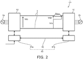
- FIG. 2 is a block diagram illustrating a direct current power transmission system.
- the communication network 60 of the direct current power transmission system 1 includes communication devices 61a and 61b and a communication line 62.
- the communication devices 61a and 61b are installed at the two terminals of the direct current power transmission system 1.
- the communication devices 61a and 61b can transmit data, commands, etc., mutually via the communication line 62.
- the data, the commands, etc., from a control system, which is a higher level of the direct current power transmission system 1, are transmitted to at least one of the communication device 61a or 61b.
- the power conversion devices 10 and 50 startup, stop, perform power flow reversal, transmit direct current power corresponding to the voltage command value and the current command value, etc.
- the power conversion device 50 of the power transmission end performs direct current control (ACR), and the power conversion device 10 of the power receiving end performs direct current voltage control (AVR).
- ACR direct current control
- AVR direct current voltage control
- the power conversion device 50 of the power transmission end it is favorable for the power conversion device 50 of the power transmission end to transmit power at the rated voltage.
- direct current voltage control of the direct current voltage Vdo of the power transmission end to the voltage command value Vdp is performed so that the direct current voltage Vdo of the power transmission end does not exceed the rated voltage.
- the direct current power line 3 When performing direct current power transmission, the direct current power line 3 has a direct current resistance portion; therefore, the direct current voltage Vds of the power receiving end has a voltage drop Vdcr corresponding to the transmitted direct current Id and the resistance value Rdce of the direct current power line 3. Because the resistance value Rdce is an estimated value, the voltage drop Vdcr also is an estimated value; the voltage control that is based on data acquired at the power receiving end side includes an error. Accordingly, in the power conversion device 10 of the power receiving end, it is favorable to perform a control so that the direct current voltage Vdo of the power transmission end that is actually measured tracks the voltage command value Vdp.
- the length of the direct current power line 3 is the distance between the AC-DC conversion stations at which the power conversion devices 10 and 50 are installed, and there are cases where the length is several 10 km to several 100 km. Therefore, the communication devices 61a and 61b are installed at the two AC-DC conversion stations; and the data of both, commands from the higher-level control system, etc., are transmitted and received via the communication line 62 provided between the communication devices 61a and 61b. In the power conversion device 10 of the power receiving end, it is necessary to receive the data of the direct current voltage Vdo of the power transmission end via a communication line.
- the normal direct current voltage undergoes constant voltage control to the rated voltage; therefore, an abrupt change of the direct current voltage does not occur. It is necessary for the normal direct current voltage to be controlled to track the rated value with high accuracy by direct current voltage control.
- the direct current voltage transiently fluctuates in the startup or stop of the power conversion devices 10 and 50, in power flow reversal, due to commutation failure, etc.
- To respond to the transient fluctuation of the direct current voltage it is necessary for the power conversion device 10 to quickly control the direct current voltage to track the transient fluctuation of the voltage.
- FIGS. 3A and 3B are block diagrams illustrating power conversion devices of comparative examples.
- FIGS. 3A and 3B show the direct current power transmission systems and the power conversion devices of the comparative examples.
- a direct current power transmission system 101a includes power conversion devices 110a and 150a.
- the power conversion devices 110a and 150a are connected by the direct current power line 3.
- the power conversion device 150a is the power conversion device of the power transmission end, and the power conversion device 110a is the power conversion device of the power receiving end.
- the power conversion device 150a can be connected to the terminal used as the power receiving end; in such a case, the power conversion device 110a can be connected to the terminal used as the power transmission end. This is similar for the following comparative examples as well.
- the power conversion device 110a includes a control device 130a.
- the control device 130a controls the power converter 20, which is a thyristor valve.
- the control device 130a includes an AVR 131a.
- the AVR 131a includes an adder-subtracter 136 and an arithmetic unit 137a.
- the voltage command value Vdp and the direct current voltage Vdo are input to the adder-subtracter 136.
- the adder-subtracter 136 supplies the deviation ⁇ Vd between the voltage command value Vdp and the direct current voltage Vdo to the arithmetic unit 137a.
- the arithmetic unit 137a generates the signal ⁇ relating to the control angle to set the deviation ⁇ Vd to 0.
- the arithmetic unit 137a may be a primary delay arithmetic unit or may be a PI controller, etc.
- the direct current voltage Vdo is transmitted via a high-speed communication network 160 in which data transmission is possible in which the constant periodicity and/or the transmission delay time are guaranteed. Also, the response speed of the arithmetic unit 137a of the AVR 131a is set according to the transmission speed of the high-speed communication network 160.
- the high-speed communication network 160 is used in the data transmission between the power transmission end and the power receiving end, there is a tendency for the installation cost, the operation cost, etc., of the high-speed communication network 160 to be expensive.
- security measures such as providing redundancy, etc., are taken based on the assumption of a failure of the high-speed communication network 160; considering such security measures, there is a risk that the cost burden of the high-speed communication network 160 may further increase.
- voltage control is performed by estimating the direct current voltage Vdo of the power transmission end by using the resistance value Rdce and the direct current voltage Vds of the power receiving end.
- a direct current power transmission system 101b includes power conversion devices 110b and 150b.
- the power conversion devices 110b and 150b are connected by the direct current power line 3.
- the power conversion device 110b of the power receiving end includes a control device 130b.
- the control device 130b includes an AVR 131b that is different from that of the comparative example described above.
- the AVR 131b includes the multiplier 34, adder-subtracters 135 and 136, and an arithmetic unit 137b.
- the data of a detected direct current Id and the data of a preset resistance value Rdce are input to the multiplier 34.
- the multiplier 34 multiplies the direct current Id and the resistance value Rdce and outputs the voltage drop Vdcr due to the direct current power line 3. Because the resistance value Rdce that is used is an estimated value, the voltage drop Vdcr is an estimated value.
- the data of the voltage drop Vdcr and the voltage command value Vdp are input to the adder-subtracter 135.
- the adder-subtracter 135 outputs the direct current voltage command value Vdp1 that considers the voltage drop Vdcr, and supplies the output to the adder-subtracter 136.
- the adder-subtracter 136 calculates a deviation ⁇ Vd1 between the direct current voltage Vds of the power receiving end and the voltage command value Vdp1 that considers the voltage drop Vdcr, and supplies the deviation ⁇ Vd1 to the arithmetic unit 137b.
- the arithmetic unit 137b generates the signal ⁇ relating to the control angle to cause the deviation Vd1 to be zero.
- the AVR 131b does not obtain the data of the direct current voltage to be controlled from the power transmission end. Instead, the AVR 131b acquires the data of the direct current voltage Vds of the power receiving end. Therefore, it is possible to construct a direct current power transmission system with the power conversion device 110b without providing a high-speed communication network.
- the AVR 131b estimates the voltage difference between the direct current voltages Vdo and Vds of the power transmission end and the power receiving end by using the voltage drop Vdcr due to the resistance value Rdce.
- the estimated value Rdce is determined by multiplying the direct current resistance value per unit length of the direct current power line 3 by the length of the power line. Therefore, the voltage command value Vdp1 that considers the voltage drop Vdcr includes at least an error accompanying the estimation of the line resistance value.
- the accuracy of the direct current voltage control of the power conversion device 110b of the power receiving end decreases.
- the direct current voltage Vdo of the power transmission end cannot exceed the rated direct current voltage; therefore, by considering the error, the direct current voltage command value Vdp1 that considers the voltage drop portion must be set to a lower value, and there is a risk that the power transmission efficiency may decrease.
- the power conversion device 10 of the embodiment includes the two controllers 32 and 33.
- the controller 32 forms a control loop capable of a fast response.
- the arithmetic unit 37 quickly performs the direct current voltage control based on the direct current voltage Vds that is detected at the power receiving end and the direct current voltage Vdo of the power transmission end that is estimated. Therefore, even when a disturbance causes an abrupt change of the direct current voltage such as at startup or the like, the power conversion device 10 can perform the direct current voltage control to respond to the disturbance.
- the controller 33 forms a control loop having a slower response than the control loop of the controller 32.
- the arithmetic unit 39 generates the control amount u based on the voltage command value Vdp and the direct current voltage Vdo of the power transmission end that is actually measured and acquired via the communication network 60.
- the control amount u that is generated has a value that reflects the direct current voltage Vdo of the power transmission end.
- the control amount u that is generated by the controller 33 is supplied to the controller 32 and used to correct the direct current voltage command value Vdp1 considering the estimated value of the voltage drop Vdcr based on the estimated value Rdce. Because the control amount u reflects the direct current voltage Vdo of the power transmission end, the error of the voltage drop due to the direct current power line 3 can be corrected, and the accuracy of the direct current voltage control can be increased. Because the transient fluctuation of the direct current voltage is tracked by the controller 32, it is sufficient for the response speed of the controller 33 to be set according to the transfer delay of the communication network 60.
- the direct current voltage Vdo of the power transmission end can be set to the rated direct current voltage with high accuracy, and the power transmission efficiency can be increased.
- the response of the controller 33 it is sufficient for the response of the controller 33 to be enough to track the normal voltage control response; also, the transmission speed of the communication network 60 does not require constant periodicity, etc. Therefore, the cost of constructing the communication network 60 can be reduced, and the operation cost, etc., also can be reduced.
- FIG. 4 is a block diagram illustrating a power conversion device according to the embodiment.
- a direct current power transmission system 201 includes power conversion devices 210 and 250.
- the power conversion device 210 is connected to the power receiving end, and the power conversion device 250 is connected to the power transmission end.
- the terminal to which the power conversion device 210 is connected can be used as the power transmission end; in such a case, the terminal to which the power conversion device 250 is connected is used as the power receiving end. This is similar for the other embodiments described below as well.
- the power conversion device 210 includes a control device 230.
- the control device 230 includes an AVR 231.
- the configuration of a portion of the AVR 231 is different from those of the other embodiments described above, and the rest of the configuration is the same.
- the same components are marked with the same reference numerals, and a detailed description is omitted as appropriate.
- the AVR 231 includes controllers 232 and 233.
- the controllers 232 and 233 are provided in parallel, and the outputs of the controllers 232 and 233 are switched by a switcher 241. According to the output of a comparator 242, the switcher 241 supplies the output of the controller 232 or the output of the controller 233 to the phase controller 40.
- the comparator 242 is connected to the output of the adder-subtracter 36.
- the output of the adder-subtracter 36 is also connected to the input of the arithmetic unit 37.
- the comparator 242 supplies the output of the controller 232 to the phase controller 40.
- the comparator 242 supplies the output of the controller 233 to the phase controller 40.
- the threshold ⁇ Vdth is set by determining an appropriate value by experiment, simulation, etc.
- the controllers 232 and 233 do not simultaneously operate because the outputs of the controllers 232 and 233 are appropriately switched. Therefore, the interference that may be caused by the setting of the response speeds can be avoided.
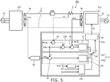
- FIG. 5 is a block diagram illustrating a power conversion device according to the embodiment.
- a direct current power transmission system 301 includes power conversion devices 310 and 350.
- the power conversion device 310 includes a control device 330.
- the configuration of the AVR 231 is the same as that of the second embodiment described above, but the control device 330 differs from that of the second embodiment described above in that the control device 330 includes an OR circuit 342.
- the OR circuit 342 receives input of multiple logical values.
- the output of the controller 233 is supplied to the phase controller 40 by the switcher 241.
- One of the three logical values is a signal D1 that is set to the H level when at least one of the power conversion device 310 or 350 is in the startup or when stopped.
- Another one of the three logical values is a signal D2 that is set to the H level in power flow reversal.
- a comparator 343 receives input of the direct current voltage Vds, calculates a change dVds / dt per unit time, and compares to a preset threshold. When dVds / dt is not less than the threshold, the comparator 343 transitions to the H level.
- the level of the fluctuation of the direct current voltage and the operating states of the power conversion devices 310 and 350 are predefined; therefore, the switching of the control loops can be reliably performed, and a smooth operation of the system is possible.
- FIG. 6 is a block diagram illustrating a power conversion device according to the embodiment.
- a direct current power transmission system 401 includes power conversion devices 410 and 450.
- the power conversion device 410 includes a control device 430.
- the control device 430 includes an AVR 431.
- the AVR 431 differs from those of the other embodiments described above in that the AVR 431 includes an arithmetic unit 437 and limiter setters 444 and 445.
- the AVR 431 differs from those of the other embodiments described above in that the AVR 431 includes an adder 446.
- a controller 432 that forms a fast control loop includes the arithmetic unit 437.
- the arithmetic unit 437 includes limiters.
- the limiters of the arithmetic unit 437 are set to different limit values according to the outputs of the limiter setters 444 and 445.
- the outputs of the limiter setters 444 and 445 are set according to the magnitude of the deviation ⁇ Vd output from an adder-subtracter 236.
- the limiter setter 444 sets a positive limit value.
- the limiter setter 445 sets a negative limit value.
- the limiter setter 444 sets zero as the limit value.
- the limiter setter 444 sets a positive limit value that is set according to the output dynamic range of the arithmetic unit 437, etc.
- the limiter setter 445 sets zero as the limit value.
- the limiter setter 445 sets a negative limit value that is set according to the output dynamic range of the arithmetic unit 437, etc.
- the output of the arithmetic unit 437 is zero because the limiter setters 444 and 445 set the limiter of the arithmetic unit 437 to zero.
- the output of the controller 432 is added to the output of a controller 433 by the adder 446; therefore, when the magnitude of the deviation ⁇ Vd is small, the output of the controller 433 that forms the slow control loop is supplied to the phase controller 40.
- the arithmetic unit 437 can output up to the limit values set by the limiter setters 444 and 445. Therefore, the output of the controller 432 that forms the fast control loop is supplied to the phase controller 40.
- the output of the controller 432 includes addition of the output of the controller 233 by the adder 446. In other words, the output of the controller 432 that forms the fast control loop is corrected by the output of the controller 233 that forms the slower control loop.
- the smaller limit value for the limiter setters 444 and 445 is not limited to zero, and it is sufficient to be a sufficiently small value compared to the larger limit value.
- the smaller limit value may be a value that has about one or two fewer digits than the larger limit value.
- a highly accurate voltage control is performed by the slow control loop of the controller 433 when the fluctuation of the direct current voltage is small.
- a fast and stable operation is performed by forming the fast control loop of the controller 432 while ensuring the voltage accuracy by using the controller 433.
Landscapes
- Engineering & Computer Science (AREA)
- Power Engineering (AREA)
- Inverter Devices (AREA)
- Supply And Distribution Of Alternating Current (AREA)
- Direct Current Feeding And Distribution (AREA)
Abstract
Description
- An embodiment of the invention relates to a control device and a power conversion device.
- In a direct current power transmission system, there are cases where a configuration is employed in which the direct current voltage of the power transmission end (the REC end) is controlled using the direct current of the power receiving end (the INV end). Thus, when controlling the direct current voltage of the opposite end, it is necessary to transfer the direct current voltage detected values of the terminals between the terminals by high-speed communication to increase the accuracy and the responsiveness of the control.
- Because a dedicated communication line is necessary for the high-speed communication between the terminals, the installation cost of the communication line is expensive compared to a system performing the communication between the terminals with a general-purpose communication line.
- Also, there are cases where the direct current voltage of the opposite end is estimated using an estimated value of the direct current resistance of the power line and the direct current voltage of it's own end without using a high-speed communication line. In such a case, an error is included between the estimated value and the actual direct current voltage value; when the error is large, there is a risk that the operation of the system may be difficult to continue.
- Patent Literature 1:
JP-B 3506881 - Embodiments of the invention provide a control device and a power conversion device that are connected to a direct current power transmission system and can be operated without using a high-speed communication line.
- According to an embodiment of the invention, a control device capable of controlling a power converter connected to one terminal of a direct current power transmission system transmitting power by a direct current power line and capable of receiving, via a communication network, data of a direct current voltage actually measured at another terminal of the direct current power transmission system is provided. The control device includes a first controller, a second controller, and a drive signal generator. The first controller includes a first arithmetic unit generating a first control output based on a voltage drop, a voltage command value, and a first direct current voltage; the voltage drop is with respect to a voltage of the other terminal estimated based on an estimated value of a direct current resistance of the direct current power line; the voltage command value sets a direct current voltage of the other terminal; and the first direct current voltage is a direct current voltage of the one terminal. The second controller includes a second arithmetic unit generating a second control output based on the voltage command value and a second direct current voltage, and the second direct current voltage is a direct current voltage actually measured at the other terminal. The drive signal generator generates a drive signal of the power converter based on the first and second control outputs. A response speed of the second arithmetic unit is set according to a transmission delay time of the communication network. A response speed of the first arithmetic unit is set to be faster than the response speed of the second arithmetic unit.
- According to embodiments of the invention, the response speed of the second arithmetic unit can be set according to the transmission delay time of the communication network, and the response speed of the first arithmetic unit can be set to be faster than the response speed of the second arithmetic unit; therefore, the direct current voltage of the power transmission end can be controlled with high accuracy regardless of a high-speed communication line.
-
- [FIG. 1]
FIG. 1 is a block diagram illustrating a power conversion device according to a first embodiment. - [FIG. 2]
FIG. 2 is a block diagram illustrating a direct current power transmission system. - [FIG. 3]
FIGS. 3A and 3B show the direct current power transmission systems and the power conversion devices of the comparative examples. - [FIG. 4]
FIG. 4 is a block diagram illustrating a power conversion device according to a second embodiment. - [FIG. 5]
FIG. 5 is a block diagram illustrating a power conversion device according to a third embodiment. - [FIG. 6]
FIG. 6 is a block diagram illustrating a power conversion device according to a fourth embodiment. - Various embodiments are described below with reference to the accompanying drawings.
- The drawings are schematic and conceptual; and the relationship between the thickness and width of the portions, the proportions of sizes among portions, etc., are not necessarily the same as the actual values. Also, the dimensions and proportions may be illustrated differently among drawings, even when the same portion is illustrated.
- In the specification and drawings, components similar to those described previously or illustrated in an antecedent drawing are marked with the same reference numerals, and a detailed description is omitted as appropriate.
-
FIG. 1 is a block diagram illustrating a power conversion device according to the embodiment. - The configuration of a direct current power transmission system 1 also is shown in
FIG. 1 . As shown inFIG. 1 , the direct current power transmission system 1 includes twopower conversion devices current power line 3. Thepower conversion device 10 is connected between the directcurrent power line 3 and an alternatingcurrent circuit 2b. Thepower conversion device 50 is connected between an alternatingcurrent circuit 2a and the directcurrent power line 3. For example, the alternatingcurrent circuits current circuits - In the example, one
power conversion device 50 is connected to the power transmission end that transmits direct current power, and the otherpower conversion device 10 is connected to the power receiving end that receives the direct current power. In the direct current power transmission system 1, the transmission of bidirectional direct current power is possible, and the terminal to which thepower conversion device 50 is connected can be used as the power receiving end; in such a case, the terminal to which thepower conversion device 10 is connected can be used as the power transmission end. Thepower conversion devices power conversion device 10 is described below. - Although a direct current power transmission system that includes two terminals is described hereinbelow, the power conversion device is applicable to a multi-terminal direct current power transmission system including three or more terminals in all of the embodiments.
- The
power conversion device 10 includes apower converter 20 and acontrol device 30. Thepower converter 20 converts the transmitted direct current voltage into an alternating current voltage and outputs the alternating current voltage according to a gate signal vg generated by thecontrol device 30. Thepower converter 20 is, for example, a thyristor valve, and the description hereinbelow is for a thyristor valve. The power converter is not limited to a separately-excited converter such as a thyristor valve and may be a self-commutated inverter circuit. - The
control device 30 generates the gate signal vg based on direct current voltages Vds and Vdo and a direct current Id and supplies the generated gate signal vg to thepower converter 20. The direct current voltage Vds is the actual measured value of the direct current terminal voltage of thepower conversion device 10 of the power receiving end. The direct current voltage Vds is detected by a directcurrent voltage detector 5b. The direct current voltage Vdo is the actual measured value of the direct current terminal voltage of thepower conversion device 50 of the power transmission end. The direct current voltage Vdo is detected by a directcurrent voltage detector 5a. The direct current Id is the actual measured value of the current flowing through the directcurrent power line 3. The direct current Id is detected by a directcurrent detector 6. - The
control device 30 includes an automatic voltage regulator (AVR) 31. Thecontrol device 30 includes aphase controller 40 connected to theAVR 31, and the phase controller (the drive signal generator) 40 generates the gate signal vg based on a signal α relating to the control angle of the thyristor from theAVR 31. For example, the signal α has a large value according to the control angle, and in thephase controller 40, generates the gate signal to increase the control angle of the thyristor. - The
AVR 31 includes twocontrollers controller 32 forms a control loop corresponding to a fast response, and thecontroller 33 forms a control loop having a lower speed than the control loop of thecontroller 32. The response speed of thecontroller 33 is set according to the transmission delay time of acommunication network 60. Thecommunication network 60 is a general-purpose communication network and does not always guarantee the constant periodicity, the transmission delay time, etc., of the data transmission. - The
controller 33 receives the input of the direct current voltage Vdo and a direct current voltage command value Vdp and generates a control output (a second control output) u for thecontroller 32. The control output u corrects the control output of thecontroller 32. The data of the direct current voltage Vdo is transmitted to the power receiving end from the power transmission end via thecommunication network 60. The direct current voltage command value Vdp is preset and is, for example, the rated value of the direct current voltage at the power transmission end. - The
controller 32 generates a control output (a first control output) based on the direct current voltage Vds of the power receiving end, the estimated value of the voltage drop of the directcurrent power line 3, and the direct current voltage command value Vdp and outputs the signal α relating to the control angle. The estimated value of the voltage drop is determined based on the direct current Id and the direct current line resistance estimated value Rdce. The direct current line resistance estimated value Rdce is an estimated value of the direct current resistance Rdc of the directcurrent power line 3 and is preset. Hereinbelow, the direct current voltage command value Vdp also is called simply the voltage command value Vdp, and the direct current line resistance estimated value Rdce also is called simply the resistance value Rdce. - Configuration examples of the
controllers - The
controller 32 includes amultiplier 34, adder-subtracters 35 and 36, and anarithmetic unit 37. - The resistance value Rdce and the actual measurement data of the direct current Id are input to the
multiplier 34. Themultiplier 34 outputs the arithmetic result of Id×Rdce. Id×Rdce represents a voltage drop Vdcr due to the resistance value Rdce. Because the resistance value Rdce is an estimated value, the voltage drop Vdcr also is an estimated value. - The voltage drop Vdcr, the voltage command value Vdp, and the control output u are input to the adder-
subtracter 35. The adder-subtracter 35 outputs a difference Vdp1 between Vdp and (Vdcr - u) and supplies the output difference Vdp1 to the adder-subtracter 35. The difference Vdp1 is the converted value of the voltage command value Vdp at the power receiving end. The converted value of the voltage command value corresponds to the direct current voltage Vdo of the power transmission end considering the voltage drop Vdcr due to the directcurrent power line 3. - The difference Vdp1 and the direct current voltage Vds are input to the adder-
subtracter 36. The adder-subtracter 36 calculates a deviation ΔVd between the difference Vdp1 and the direct current voltage Vds and supplies the deviation ΔVd to thearithmetic unit 37. - For example, the
arithmetic unit 37 performs a primary delay calculation. Thearithmetic unit 37 performs the primary delay calculation of the deviation ΔVd and generates the signal α relating to the control angle. The response speed of thearithmetic unit 37 is set to be sufficiently fast to be able to track an abrupt change of the direct current voltages Vds and Vdo including commutation failures, etc. When thearithmetic unit 37 is a primary delay arithmetic unit, it is favorable for the primary delay time constant to have a sufficiently small value. Thearithmetic unit 37 is not limited to an arithmetic unit that performs a primary delay calculation and may be, for example, a PI controller, etc. For a PI controller, it is favorable for the integration constant to have a sufficiently large value to track an abrupt change of the direct current voltages Vds and Vdo. - The
controller 33 includes an adder-subtracter 38 and anarithmetic unit 39. The data of the voltage command value Vdp and the data of the direct current voltage Vdo are input to the adder-subtracter 38. The data of the direct current voltage Vdo is transmitted via thecommunication network 60. Thecommunication network 60 is a general-purpose communication network and may include, for example, a line of the Internet or the like that uses a general-purpose Ethernet (registered trademark). The adder-subtracter 38 supplies the deviation between the voltage command value Vdp and the direct current voltage Vdo to thearithmetic unit 39. - For example, the
arithmetic unit 39 performs a primary delay calculation. Thearithmetic unit 39 generates the control output u by performing a primary delay calculation of the deviation. Thearithmetic unit 39 is not limited to a primary delay arithmetic unit and may be a PI controller, etc. The response speed of thearithmetic unit 39 is set according to the transmission delay time of thecommunication network 60. The response speed of thearithmetic unit 39 may be set to be slow compared to the response speed of thearithmetic unit 37. - The
controller 32 can respond to an abrupt change of the direct current voltages Vds and Vdo and can obtain a sufficient control response for disturbances such as an abrupt change of the direct current voltage in the startup or stop of thepower conversion devices - The
controller 33 can perform voltage control with high accuracy because the direct current voltage Vdo of the power transmission end that is used is actually measured. By using the control output u to correct the output of thecontroller 32, the error when estimating the direct current voltage Vdo of the power transmission end in thecontroller 32 can be corrected. - In the description described above, an example is described in which the control output u that is generated by the
controller 33 is added simultaneously with Vdp and Vdcr by the adder-subtracter 35; however, the position of the addition is not limited thereto as long as the correction by the control output u is performed before the signal is input to thearithmetic unit 37. For example, the addition may be performed after calculating the difference between Vdp and Vdcr and before calculating the deviation by the adder-subtracter 36, or the addition may be performed after calculating the deviation by the adder-subtracter 36. - The components described above for the
control device 30 including theAVR 31 may be realized by an arithmetic device including a CPU (Central Processing Unit), an MPU (Micro Processing Unit), etc. Some or all of the components described above may be realized by being sequentially executed by a program stored in a memory device connected to the arithmetic device. This is similar for the other embodiments described below as well. - Effects of the power conversion device of the embodiment will now be described while comparing to a power conversion device of a comparative example.
-
FIG. 2 is a block diagram illustrating a direct current power transmission system. - As shown in
FIG. 2 , thecommunication network 60 of the direct current power transmission system 1 includescommunication devices communication line 62. Thecommunication devices communication devices communication line 62. The data, the commands, etc., from a control system, which is a higher level of the direct current power transmission system 1, are transmitted to at least one of thecommunication device - According to the data, the commands, etc., transmitted and received via the
communication network 60, thepower conversion devices - Describing now an example more specifically, to perform direct current power transmission, the
power conversion device 50 of the power transmission end performs direct current control (ACR), and thepower conversion device 10 of the power receiving end performs direct current voltage control (AVR). To increase the efficiency of the power transmission to the utmost, it is favorable for thepower conversion device 50 of the power transmission end to transmit power at the rated voltage. In thepower conversion device 10 of the power receiving end, direct current voltage control of the direct current voltage Vdo of the power transmission end to the voltage command value Vdp is performed so that the direct current voltage Vdo of the power transmission end does not exceed the rated voltage. - When performing direct current power transmission, the direct
current power line 3 has a direct current resistance portion; therefore, the direct current voltage Vds of the power receiving end has a voltage drop Vdcr corresponding to the transmitted direct current Id and the resistance value Rdce of the directcurrent power line 3. Because the resistance value Rdce is an estimated value, the voltage drop Vdcr also is an estimated value; the voltage control that is based on data acquired at the power receiving end side includes an error. Accordingly, in thepower conversion device 10 of the power receiving end, it is favorable to perform a control so that the direct current voltage Vdo of the power transmission end that is actually measured tracks the voltage command value Vdp. - On the other hand, the length of the direct
current power line 3 is the distance between the AC-DC conversion stations at which thepower conversion devices communication devices communication line 62 provided between thecommunication devices power conversion device 10 of the power receiving end, it is necessary to receive the data of the direct current voltage Vdo of the power transmission end via a communication line. - The normal direct current voltage undergoes constant voltage control to the rated voltage; therefore, an abrupt change of the direct current voltage does not occur. It is necessary for the normal direct current voltage to be controlled to track the rated value with high accuracy by direct current voltage control.
- The direct current voltage transiently fluctuates in the startup or stop of the
power conversion devices power conversion device 10 to quickly control the direct current voltage to track the transient fluctuation of the voltage. -
FIGS. 3A and 3B are block diagrams illustrating power conversion devices of comparative examples. -
FIGS. 3A and 3B show the direct current power transmission systems and the power conversion devices of the comparative examples. - As shown in
FIG. 3A , a direct currentpower transmission system 101a includespower conversion devices power conversion devices current power line 3. Thepower conversion device 150a is the power conversion device of the power transmission end, and thepower conversion device 110a is the power conversion device of the power receiving end. Similarly to the first embodiment described above, thepower conversion device 150a can be connected to the terminal used as the power receiving end; in such a case, thepower conversion device 110a can be connected to the terminal used as the power transmission end. This is similar for the following comparative examples as well. - The
power conversion device 110a includes acontrol device 130a. For example, thecontrol device 130a controls thepower converter 20, which is a thyristor valve. Thecontrol device 130a includes anAVR 131a. TheAVR 131a includes an adder-subtracter 136 and anarithmetic unit 137a. - The voltage command value Vdp and the direct current voltage Vdo are input to the adder-
subtracter 136. The adder-subtracter 136 supplies the deviation ΔVd between the voltage command value Vdp and the direct current voltage Vdo to thearithmetic unit 137a. Thearithmetic unit 137a generates the signal α relating to the control angle to set the deviation ΔVd to 0. Thearithmetic unit 137a may be a primary delay arithmetic unit or may be a PI controller, etc. - In order for the
AVR 131a to respond to the transient fluctuation of the direct current voltage Vdo, the direct current voltage Vdo is transmitted via a high-speed communication network 160 in which data transmission is possible in which the constant periodicity and/or the transmission delay time are guaranteed. Also, the response speed of thearithmetic unit 137a of theAVR 131a is set according to the transmission speed of the high-speed communication network 160. - For a comparative example such as that described above, because the high-
speed communication network 160 is used in the data transmission between the power transmission end and the power receiving end, there is a tendency for the installation cost, the operation cost, etc., of the high-speed communication network 160 to be expensive. When used in a power system of a main system such as a direct current power transmission system, security measures such as providing redundancy, etc., are taken based on the assumption of a failure of the high-speed communication network 160; considering such security measures, there is a risk that the cost burden of the high-speed communication network 160 may further increase. - Power conversion devices that realize sufficient responsiveness without using an expensive high-speed communication network are being put into practical use. In the comparative example of
FIG. 3B , voltage control is performed by estimating the direct current voltage Vdo of the power transmission end by using the resistance value Rdce and the direct current voltage Vds of the power receiving end. - A direct current
power transmission system 101b includespower conversion devices power conversion devices current power line 3. Thepower conversion device 110b of the power receiving end includes acontrol device 130b. Thecontrol device 130b includes anAVR 131b that is different from that of the comparative example described above. TheAVR 131b includes themultiplier 34, adder-subtracters arithmetic unit 137b. - The data of a detected direct current Id and the data of a preset resistance value Rdce are input to the
multiplier 34. Themultiplier 34 multiplies the direct current Id and the resistance value Rdce and outputs the voltage drop Vdcr due to the directcurrent power line 3. Because the resistance value Rdce that is used is an estimated value, the voltage drop Vdcr is an estimated value. - The data of the voltage drop Vdcr and the voltage command value Vdp are input to the adder-
subtracter 135. The adder-subtracter 135 outputs the direct current voltage command value Vdp1 that considers the voltage drop Vdcr, and supplies the output to the adder-subtracter 136. - The adder-
subtracter 136 calculates a deviation ΔVd1 between the direct current voltage Vds of the power receiving end and the voltage command value Vdp1 that considers the voltage drop Vdcr, and supplies the deviation ΔVd1 to thearithmetic unit 137b. - The
arithmetic unit 137b generates the signal α relating to the control angle to cause the deviation Vd1 to be zero. - In the comparative example, the
AVR 131b does not obtain the data of the direct current voltage to be controlled from the power transmission end. Instead, theAVR 131b acquires the data of the direct current voltage Vds of the power receiving end. Therefore, it is possible to construct a direct current power transmission system with thepower conversion device 110b without providing a high-speed communication network. - However, the
AVR 131b estimates the voltage difference between the direct current voltages Vdo and Vds of the power transmission end and the power receiving end by using the voltage drop Vdcr due to the resistance value Rdce. For example, the estimated value Rdce is determined by multiplying the direct current resistance value per unit length of the directcurrent power line 3 by the length of the power line. Therefore, the voltage command value Vdp1 that considers the voltage drop Vdcr includes at least an error accompanying the estimation of the line resistance value. - Accordingly, in the comparative example, the accuracy of the direct current voltage control of the
power conversion device 110b of the power receiving end decreases. Also, the direct current voltage Vdo of the power transmission end cannot exceed the rated direct current voltage; therefore, by considering the error, the direct current voltage command value Vdp1 that considers the voltage drop portion must be set to a lower value, and there is a risk that the power transmission efficiency may decrease. - Unlike these comparative examples, the
power conversion device 10 of the embodiment includes the twocontrollers controller 32 forms a control loop capable of a fast response. In thecontroller 32, thearithmetic unit 37 quickly performs the direct current voltage control based on the direct current voltage Vds that is detected at the power receiving end and the direct current voltage Vdo of the power transmission end that is estimated. Therefore, even when a disturbance causes an abrupt change of the direct current voltage such as at startup or the like, thepower conversion device 10 can perform the direct current voltage control to respond to the disturbance. - In the direct current power transmission system 1, the
controller 33 forms a control loop having a slower response than the control loop of thecontroller 32. In thecontroller 33, thearithmetic unit 39 generates the control amount u based on the voltage command value Vdp and the direct current voltage Vdo of the power transmission end that is actually measured and acquired via thecommunication network 60. The control amount u that is generated has a value that reflects the direct current voltage Vdo of the power transmission end. - The control amount u that is generated by the
controller 33 is supplied to thecontroller 32 and used to correct the direct current voltage command value Vdp1 considering the estimated value of the voltage drop Vdcr based on the estimated value Rdce. Because the control amount u reflects the direct current voltage Vdo of the power transmission end, the error of the voltage drop due to the directcurrent power line 3 can be corrected, and the accuracy of the direct current voltage control can be increased. Because the transient fluctuation of the direct current voltage is tracked by thecontroller 32, it is sufficient for the response speed of thecontroller 33 to be set according to the transfer delay of thecommunication network 60. - Because the accuracy of the direct current voltage control can be increased by the
controller 33, the direct current voltage Vdo of the power transmission end can be set to the rated direct current voltage with high accuracy, and the power transmission efficiency can be increased. - It is sufficient for the response of the
controller 33 to be enough to track the normal voltage control response; also, the transmission speed of thecommunication network 60 does not require constant periodicity, etc. Therefore, the cost of constructing thecommunication network 60 can be reduced, and the operation cost, etc., also can be reduced. -
FIG. 4 is a block diagram illustrating a power conversion device according to the embodiment. - As shown in
FIG. 4 , a direct currentpower transmission system 201 includespower conversion devices power conversion device 210 is connected to the power receiving end, and thepower conversion device 250 is connected to the power transmission end. Similarly to the first embodiment, the terminal to which thepower conversion device 210 is connected can be used as the power transmission end; in such a case, the terminal to which thepower conversion device 250 is connected is used as the power receiving end. This is similar for the other embodiments described below as well. - The
power conversion device 210 includes acontrol device 230. Thecontrol device 230 includes anAVR 231. In thecontrol device 230, the configuration of a portion of theAVR 231 is different from those of the other embodiments described above, and the rest of the configuration is the same. Similarly, for the other embodiments described below as well, the same components are marked with the same reference numerals, and a detailed description is omitted as appropriate. - The
AVR 231 includescontrollers controllers controllers switcher 241. According to the output of acomparator 242, theswitcher 241 supplies the output of thecontroller 232 or the output of thecontroller 233 to thephase controller 40. - The
comparator 242 is connected to the output of the adder-subtracter 36. The output of the adder-subtracter 36 is also connected to the input of thearithmetic unit 37. When the deviation ΔVd is less than a preset threshold ΔVdth, thecomparator 242 supplies the output of thecontroller 232 to thephase controller 40. When the deviation ΔVd is not less than the threshold ΔVdth, thecomparator 242 supplies the output of thecontroller 233 to thephase controller 40. The threshold ΔVdth is set by determining an appropriate value by experiment, simulation, etc. - In the embodiment, the
controllers controllers -
FIG. 5 is a block diagram illustrating a power conversion device according to the embodiment. - As shown in
FIG. 5 , a direct currentpower transmission system 301 includespower conversion devices power conversion device 310 includes acontrol device 330. In thecontrol device 330, the configuration of theAVR 231 is the same as that of the second embodiment described above, but thecontrol device 330 differs from that of the second embodiment described above in that thecontrol device 330 includes an ORcircuit 342. - In the embodiment, the
OR circuit 342 receives input of multiple logical values. In the example, three logical values are input; when at least one logical value is the H level (the logical value = "1"), the output of thecontroller 232 is supplied to thephase controller 40 by theswitcher 241. When all of the three logical values are the L level (the logical value = "0"), the output of thecontroller 233 is supplied to thephase controller 40 by theswitcher 241. - One of the three logical values is a signal D1 that is set to the H level when at least one of the
power conversion device comparator 343 receives input of the direct current voltage Vds, calculates a change dVds/dt per unit time, and compares to a preset threshold. When dVds/dt is not less than the threshold, thecomparator 343 transitions to the H level. - In the embodiment, the level of the fluctuation of the direct current voltage and the operating states of the
power conversion devices -
FIG. 6 is a block diagram illustrating a power conversion device according to the embodiment. - As shown in
FIG. 6 , a direct currentpower transmission system 401 includespower conversion devices power conversion device 410 includes acontrol device 430. Thecontrol device 430 includes an AVR 431. In the embodiment, the AVR 431 differs from those of the other embodiments described above in that the AVR 431 includes anarithmetic unit 437 andlimiter setters - In the embodiment, a
controller 432 that forms a fast control loop includes thearithmetic unit 437. Thearithmetic unit 437 includes limiters. The limiters of thearithmetic unit 437 are set to different limit values according to the outputs of thelimiter setters limiter setters limiter setter 444 sets a positive limit value. Thelimiter setter 445 sets a negative limit value. - More specifically, when the deviation ΔVd is less than a preset threshold, the
limiter setter 444 sets zero as the limit value. When the deviation ΔVd is not less than the threshold, thelimiter setter 444 sets a positive limit value that is set according to the output dynamic range of thearithmetic unit 437, etc. - When the absolute value of the deviation ΔVd is less than the threshold, the
limiter setter 445 sets zero as the limit value. When the absolute value of the deviation ΔVd is not less than the threshold, thelimiter setter 445 sets a negative limit value that is set according to the output dynamic range of thearithmetic unit 437, etc. - When the absolute value of the deviation ΔVd that is input is less than the threshold, the output of the
arithmetic unit 437 is zero because thelimiter setters arithmetic unit 437 to zero. The output of thecontroller 432 is added to the output of a controller 433 by the adder 446; therefore, when the magnitude of the deviation ΔVd is small, the output of the controller 433 that forms the slow control loop is supplied to thephase controller 40. - When the absolute value of the deviation ΔVd that is input to the
limiter setters arithmetic unit 437 can output up to the limit values set by thelimiter setters controller 432 that forms the fast control loop is supplied to thephase controller 40. The output of thecontroller 432 includes addition of the output of thecontroller 233 by the adder 446. In other words, the output of thecontroller 432 that forms the fast control loop is corrected by the output of thecontroller 233 that forms the slower control loop. - The smaller limit value for the
limiter setters - In the embodiment, a highly accurate voltage control is performed by the slow control loop of the controller 433 when the fluctuation of the direct current voltage is small. When the fluctuation of the direct current voltage is large, a fast and stable operation is performed by forming the fast control loop of the
controller 432 while ensuring the voltage accuracy by using the controller 433. - Hereinabove, embodiments of the invention are described with reference to specific examples. However, the invention is not limited to these specific examples. For example, one skilled in the art may similarly practice the invention by appropriately selecting specific configurations of components such as the power converter, the control device, etc., from known art, and such practice is within the scope of the invention to the extent that similar effects can be obtained.
- Also, combinations of any two or more components of the specific examples within the extent of technical feasibility also are within the scope of the invention to the extent that the spirit of the invention is included.
- Furthermore, all power conversion devices practicable by an appropriate design modification by one skilled in the art based on the power conversion devices described above as embodiments of the invention also are within the scope of the invention to the extent that the spirit of the invention is included.
- Also, various modifications and alterations within the spirit of the invention will be readily apparent to those skilled in the art, and all such modifications and alterations should be seen as being within the scope of the invention.
- Although several embodiments of the invention are described, these embodiments are presented as examples and are not intended to limit the scope of the invention. These novel embodiments may be implemented in other various forms, and various omissions, substitutions, and modifications can be performed without departing from the spirit of the invention. Such embodiments and their modifications are within the scope and spirit of the invention and are within the scope of the invention described in the claims and their equivalents.
Claims (9)
- A control device capable of controlling a power converter connected to one terminal of a direct current power transmission system transmitting power by a direct current power line, and capable of receiving, via a communication network, data of a direct current voltage actually measured at an other terminal of the direct current power transmission system, the control device comprising:a first controller including a first arithmetic unit generating a first control output based on a voltage drop, a voltage command value, and a first direct current voltage, the voltage drop being with respect to a voltage of the other terminal estimated based on an estimated value of a direct current resistance of the direct current power line, the voltage command value setting a direct current voltage of the other terminal, the first direct current voltage being a direct current voltage of the one terminal;a second controller including a second arithmetic unit generating a second control output based on the voltage command value and a second direct current voltage, the second direct current voltage being a direct current voltage actually measured at the other terminal; anda drive signal generator generating a drive signal of the power converter based on the first and second control outputs,a response speed of the second arithmetic unit being set according to a transmission delay time of the communication network,a response speed of the first arithmetic unit being set to be faster than the response speed of the second arithmetic unit.
- The control device according to claim 1, wherein
the first control output is corrected using the second control output. - The control device according to claim 2, wherein
the second control output corrects the first control output by being input to the first arithmetic unit. - The control device according to claim 2, wherein
the first arithmetic unit:sets a magnitude of an output of the first arithmetic unit to a prescribed amplitude when a magnitude of a signal that is input is not less than a prescribed threshold; andincludes an output limiter set to a greater value than the prescribed amplitude when the magnitude of the signal that is input is less than the threshold, andthe second control output is added to the first control output in the output of the first arithmetic unit. - The control device according to claim 1, wherein
the first control output and the second control output are used by being switched based on a preset condition. - The control device according to claim 5, wherein
the preset condition is set based on a deviation between a preset direct current voltage command value and the second direct current voltage. - The control device according to claim 5, wherein
the preset condition is set based on a change of a magnitude per unit time of the second direct current voltage. - The control device according to claim 5, wherein
the preset condition is set based on a designation supplied from an external part. - A power conversion device, comprising:a power converter mutually converting an alternating current voltage and a direct current voltage; andthe control device according to claim 1.
Applications Claiming Priority (1)
| Application Number | Priority Date | Filing Date | Title |
|---|---|---|---|
| PCT/JP2018/020930 WO2019229922A1 (en) | 2018-05-31 | 2018-05-31 | Control device and power conversion device |
Publications (2)
| Publication Number | Publication Date |
|---|---|
| EP3806262A1 true EP3806262A1 (en) | 2021-04-14 |
| EP3806262A4 EP3806262A4 (en) | 2022-03-09 |
Family
ID=68697260
Family Applications (1)
| Application Number | Title | Priority Date | Filing Date |
|---|---|---|---|
| EP18920935.6A Pending EP3806262A4 (en) | 2018-05-31 | 2018-05-31 | CONTROL DEVICE AND POWER CONVERSION DEVICE |
Country Status (3)
| Country | Link |
|---|---|
| EP (1) | EP3806262A4 (en) |
| JP (1) | JP6986321B2 (en) |
| WO (1) | WO2019229922A1 (en) |
Families Citing this family (1)
| Publication number | Priority date | Publication date | Assignee | Title |
|---|---|---|---|---|
| JP7817879B2 (en) * | 2022-04-14 | 2026-02-19 | Tdk株式会社 | Power management device, upper-level power management device, power management method, and power management program |
Family Cites Families (6)
| Publication number | Priority date | Publication date | Assignee | Title |
|---|---|---|---|---|
| US3399655A (en) | 1967-04-24 | 1968-09-03 | Clayton Manufacturing Co | Forced circulation steam generator with thermal-mechanical pre-removal of corrosive gases from the liquid supplied to the heating coil |
| JPS5851736A (en) * | 1981-09-22 | 1983-03-26 | 関西電力株式会社 | Voltage controller for dc transmission system |
| JPS5953023A (en) * | 1982-09-20 | 1984-03-27 | 東京電力株式会社 | Controller in dc transmitting system |
| SE518307C2 (en) * | 1997-03-24 | 2002-09-24 | Abb Ab | Device for eliminating over-modulation in electrical system |
| JP2003037939A (en) * | 2001-07-24 | 2003-02-07 | Toshiba Corp | DC power transmission system controller |
| JP2016152733A (en) * | 2015-02-18 | 2016-08-22 | 株式会社東芝 | Control device for power converter |
-
2018
- 2018-05-31 WO PCT/JP2018/020930 patent/WO2019229922A1/en not_active Ceased
- 2018-05-31 JP JP2020522496A patent/JP6986321B2/en active Active
- 2018-05-31 EP EP18920935.6A patent/EP3806262A4/en active Pending
Also Published As
| Publication number | Publication date |
|---|---|
| EP3806262A4 (en) | 2022-03-09 |
| JPWO2019229922A1 (en) | 2021-01-14 |
| JP6986321B2 (en) | 2021-12-22 |
| WO2019229922A1 (en) | 2019-12-05 |
Similar Documents
| Publication | Publication Date | Title |
|---|---|---|
| KR101706406B1 (en) | Controlling an inverter device of a high voltage dc system for supporting an ac system | |
| EP2950443B1 (en) | Variable frequency speed control system and method of the same | |
| US10418851B2 (en) | Uninterruptible power supply device | |
| CA2826330C (en) | Control arrangement and method for regulating the output voltage of a dc source power converter connected to a multi-source dc system | |
| US10761593B2 (en) | Power control system and power control program | |
| EP3261208B1 (en) | Control device of power converter | |
| GB2545314A (en) | No break power transfer for multi-source electrical power system | |
| US20160043683A1 (en) | Motor control device and motor control method | |
| KR102224966B1 (en) | Apparatus controlling commutation failure of hvdc system | |
| US7477037B2 (en) | Method for parallel control of series-cell based drives | |
| JP6986321B2 (en) | Control device and power converter | |
| TW201503532A (en) | Power supply apparatus with controllable multiple input rectification | |
| US20220158569A1 (en) | Inverter control device and method | |
| JPH11155236A (en) | Reactive power compensation method and system | |
| US11984723B2 (en) | Multi-mode power supply system | |
| WO2021043100A1 (en) | Distributed direct current energy consumption device, control method therefor, and control module thereof | |
| JP5205654B2 (en) | Distributed DC power supply control circuit | |
| US12525786B2 (en) | Control method, device, system and storage medium | |
| CN106849146B (en) | A five-terminal high-voltage direct current transmission system | |
| EP3100331B1 (en) | Voltage regulation in multi-terminal hvdc network | |
| US7283377B2 (en) | Method for controlling firing angle under line dip situations | |
| CN110140272A (en) | Improvements in or related to the transmission network | |
| KR101096148B1 (en) | HCDC controller and HCDC system including the same | |
| JP5109484B2 (en) | Power generation system | |
| US11133671B2 (en) | Control device and power conversion device |
Legal Events
| Date | Code | Title | Description |
|---|---|---|---|
| STAA | Information on the status of an ep patent application or granted ep patent |
Free format text: STATUS: THE INTERNATIONAL PUBLICATION HAS BEEN MADE |
|
| PUAI | Public reference made under article 153(3) epc to a published international application that has entered the european phase |
Free format text: ORIGINAL CODE: 0009012 |
|
| STAA | Information on the status of an ep patent application or granted ep patent |
Free format text: STATUS: REQUEST FOR EXAMINATION WAS MADE |
|
| 17P | Request for examination filed |
Effective date: 20201130 |
|
| AK | Designated contracting states |
Kind code of ref document: A1 Designated state(s): AL AT BE BG CH CY CZ DE DK EE ES FI FR GB GR HR HU IE IS IT LI LT LU LV MC MK MT NL NO PL PT RO RS SE SI SK SM TR |
|
| AX | Request for extension of the european patent |
Extension state: BA ME |
|
| DAV | Request for validation of the european patent (deleted) | ||
| DAX | Request for extension of the european patent (deleted) | ||
| A4 | Supplementary search report drawn up and despatched |
Effective date: 20220209 |
|
| RIC1 | Information provided on ipc code assigned before grant |
Ipc: H02J 13/00 20060101ALI20220203BHEP Ipc: H02J 1/00 20060101ALI20220203BHEP Ipc: H02J 3/36 20060101AFI20220203BHEP |
|
| STAA | Information on the status of an ep patent application or granted ep patent |
Free format text: STATUS: EXAMINATION IS IN PROGRESS |
|
| 17Q | First examination report despatched |
Effective date: 20250602 |