EP3806126A1 - Assembly for and method of monitoring the status of a relay - Google Patents
Assembly for and method of monitoring the status of a relay Download PDFInfo
- Publication number
- EP3806126A1 EP3806126A1 EP19201657.4A EP19201657A EP3806126A1 EP 3806126 A1 EP3806126 A1 EP 3806126A1 EP 19201657 A EP19201657 A EP 19201657A EP 3806126 A1 EP3806126 A1 EP 3806126A1
- Authority
- EP
- European Patent Office
- Prior art keywords
- assembly
- relay
- armature
- inductance
- coil
- Prior art date
- Legal status (The legal status is an assumption and is not a legal conclusion. Google has not performed a legal analysis and makes no representation as to the accuracy of the status listed.)
- Granted
Links
Images



Classifications
-
- H—ELECTRICITY
- H01—ELECTRIC ELEMENTS
- H01H—ELECTRIC SWITCHES; RELAYS; SELECTORS; EMERGENCY PROTECTIVE DEVICES
- H01H47/00—Circuit arrangements not adapted to a particular application of the relay and designed to obtain desired operating characteristics or to provide energising current
- H01H47/002—Monitoring or fail-safe circuits
-
- H—ELECTRICITY
- H01—ELECTRIC ELEMENTS
- H01H—ELECTRIC SWITCHES; RELAYS; SELECTORS; EMERGENCY PROTECTIVE DEVICES
- H01H1/00—Contacts
- H01H1/12—Contacts characterised by the manner in which co-operating contacts engage
- H01H1/14—Contacts characterised by the manner in which co-operating contacts engage by abutting
- H01H1/20—Bridging contacts
-
- H—ELECTRICITY
- H01—ELECTRIC ELEMENTS
- H01H—ELECTRIC SWITCHES; RELAYS; SELECTORS; EMERGENCY PROTECTIVE DEVICES
- H01H47/00—Circuit arrangements not adapted to a particular application of the relay and designed to obtain desired operating characteristics or to provide energising current
- H01H2047/008—Circuit arrangements not adapted to a particular application of the relay and designed to obtain desired operating characteristics or to provide energising current with a drop in current upon closure of armature or change of inductance
-
- H—ELECTRICITY
- H01—ELECTRIC ELEMENTS
- H01H—ELECTRIC SWITCHES; RELAYS; SELECTORS; EMERGENCY PROTECTIVE DEVICES
- H01H47/00—Circuit arrangements not adapted to a particular application of the relay and designed to obtain desired operating characteristics or to provide energising current
- H01H47/22—Circuit arrangements not adapted to a particular application of the relay and designed to obtain desired operating characteristics or to provide energising current for supplying energising current for relay coil
- H01H47/32—Energising current supplied by semiconductor device
- H01H47/325—Energising current supplied by semiconductor device by switching regulator
Definitions
- the invention relates to an assembly for and a method of monitoring the status of a relay having an armature and a coil for moving the armature.
- Relays are often used for switching currents with a contact bridge that is movable relative to stationary or fixed contacts. Under faulty conditions the contact bridge can be welded to the stationary contacts for example due to an overcurrent. As this is a dangerous configuration, it is necessary to be able to monitor the switching state and/or detect such a welding. Current solutions for doing this are, however, very bulky.
- an assembly for monitoring the status of a relay having an armature and a coil for moving the armature wherein the assembly comprises an inductance measurement device adapted for measuring the inductance of the coil.
- the object is also achieved by a method of monitoring the status of a relay having an armature and a coil for moving the armature, wherein an inductance of the coil is measured.
- the inductance measurement device can comprise a current measurement device to allow a simple implementation.
- the circuit can discriminate the inductance difference between partially closed armature and fully open armature.
- the assembly can comprise an oscillator adapted for creating an alternating current. This can allow a quick measurement.
- the inventive solution can be part of a relay assembly comprising a relay and an assembly according to the invention.
- the relay and the assembly can have a common ground.
- the assembly can be connected to a control circuit of the relay. This can keep the configuration simple and compact.
- the assembly can be adapted to be connected to the control circuit of the relay. It can be added to existing relays.
- control circuit and the assembly are arranged on the same PCB. This keeps the overall device simple and compact.
- PCB can comprise additional elements for performing the measurement.
- the assembly can be connected to the relay via a capacitor.
- Relays are often operated with a direct current (DC) or a current that is similar to a direct current.
- the capacitor can thus achieve a good decoupling.
- the assembly can be arranged within a housing of the relay. This keeps the configuration compact.
- a connector of the relay assembly can comprise at least one pin for a signal of the assembly.
- signals indicative of a measurement can be transmitted.
- the signal could indicate a position or a status of the contact bridge or whether a fault condition exists.
- the pin can be used to output current or voltage that has to be processed in additional elements.
- the assembly can be arranged outside a housing of the relay.
- the assembly can then be added to existing relays without big modifications.
- the assembly can, for example, be at least partially located in a control circuit, e.g. an engine control unit.
- the armature can be at least partially located in the coil.
- the armature is located entirely or almost entirely within the coil.
- the armature can be located in a space defined by the outlines of the coil and/or a housing of the coil.
- the inductance can be measured at at least one frequency with an alternating current.
- the frequency can be selected such that a certain difference in the inductance values exists between a normal and a fault state.
- the method can comprise a step of detecting a fault state of the armature.
- a fault state can in particular be a state in which the switching has not taken place although a corresponding control signal is applied.
- the detection of the fault state can be made by comparing the measured inductance to a predefined value. If the measured inductance is below or above a certain threshold value, a fault state can be diagnosed.
- the predefined value can depend on the inductance value of a normal state and can, for example, be 20% higher or lower than such a normal state value.
- the inductance can be measured at at least two frequencies.
- the assembly or the method can be such that the status is only monitored in a non-energized state of the relay.
- the application also covers a computer program comprising instructions which, when the program is executed by a computer, cause the computer to carry out the inventive method.
- the application covers a computer-readable medium comprising instructions which, when executed by a computer, cause the computer to carry out the inventive method.
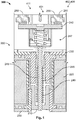
- Figs. 1 and 2 the operation of a relay 100 is depicted.
- Fig. 1 can be seen as an energized state 401 of a coil 220 that results in a closed state 411 of a load circuit 255.
- a current runs through the coil 220, which generates a magnetic field that pulls an armature 210 inwards.
- the armature 210 is coupled to a contact bridge 240 via a transfer rod 246 and an attachment assembly 247.
- a contact bridge 240 is thus pushed onto two fixed contacts 250 of a load circuit 255 and closes the load circuit 255.
- a non-energized state 402 of the coil 220 resulting in an open state 412 of the load circuit 255 is shown.
- the armature 210 is pushed outwards by a spring 245.
- the contact bridge 240 is thus pulled away from the fixed contacts 250 so that the load circuit 255 is open.
- Fig. 1 can also be seen as showing such a fault state 406 in which the load circuit 255 is closed or almost closed although the coil 220 is in a non-energized state 402.
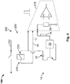
- the relay assembly 300 can comprise an assembly 100 that comprises an inductance measurement device 10 adapted for measuring the inductance of the coil 220. Details of such embodiments are shown in Figs. 3 and 4 .
- the inductance of the coil 220 depends on the position of the armature 210 in the coil 220. In case of a fault condition, in which the contact bridge 240 is welded to at least one fixed contact 250, the armature 210 cannot move back although the coil 220 is not energized. In the embodiment of Fig. 3 , two coils 220 are present, wherein one of the coils 220 can be activated selectively by a transistor 56.
- the assembly 100 can more generally be adapted to detect or measure the position of the armature 210. Such a position measurement can, for example, be used to detect further fault conditions. For example, the movement profile of the armature 210 can be analyzed to check whether the friction is increased. Further, the assembly 100 could be used to detect the tear and wear of contact elements 241 located on the contact bridge 240 and the fixed contacts 250. Such contact elements 241 are used up during the lifetime of the relay 200. The lack of enough material in the contact elements 241 can cause dangerous situations. The assembly 100 can be adapted to detect such conditions, for example by detecting an increased movement span of the armature 210.
- the assembly comprises an oscillator 20 adapted for creating an alternating current.
- the frequency of the alternating current can be constant or variable.
- the alternating current is used for measuring the inductance in the coil 220.
- the inductance measurement device 10 comprises a current measurement device 15 that measures the current resulting in the circuit.
- the current in the circuit depends on the inductance of the coil 220.
- the inductance measurement device 10 is adapted to calculate the maximum current measured with the current measurement device 15.
- the relay 200 and the assembly 100 have a common ground 40 in order to simplify the electrical layout and in order to keep the number of pins 60 that are necessary for contacting the relay assembly 300 low.
- three pins 60 are necessary, which is only one pin more than a relay 200 without an assembly 100.
- a schematically shown connector 62 having the pins in a housing 64 can thus be similar in size to a connector with only two pins 60.
- the assembly 100 is connected to a control circuit 215 of the relay 200, which is shown only schematically.
- the assembly 100 can be arranged on the same PCB as the control circuit 215.
- a capacitor 50 can be used to decouple a control signal for the switching of the relay 200, which is a direct current, or a signal similar to a direct current, from the alternating current used in the assembly 100.
- the assembly 100 is arranged within a housing 230 of the relay 200.
- the assembly 100 can be arranged outside a housing 230 of the relay 200, for example in an external control circuit or an engine control unit. In such a configuration, it could suffice to use only two pins 60 in the connector 62, as the necessary contacts to the circuit of the coil 220 can be made outside of the housing 230.
- the armature 210 is at least partially located in the coil 220 and/or in the housing 230 of the coil 220.
- an inductance of the coil 220 is measured.
- the method can be adapted to detect a fault state of the armature 210 by comparing the measured inductance to a predefined value.
- the inductance can be measured at at least two frequencies.
- the method is only used and the status is only monitored in a non-energized state of the relay. It is then not necessary to compensate effects due to the operation of the relay 200.
- a graph showing the different inductive behavior of a relay 200 in an open position 412 and a fault state 406 is shown.
- the graph shows an inductance signal in arbitrary units on the ordinate over the frequency of the alternating current used for the measurement on the abscissa. It can be seen that at certain frequencies, a distinct difference between the two conditions exists. The measurement should be made at such a frequency. The frequency at which such a difference exists of course depends on the specific case.
Landscapes
- Testing Electric Properties And Detecting Electric Faults (AREA)
Abstract
Description
- The invention relates to an assembly for and a method of monitoring the status of a relay having an armature and a coil for moving the armature.
- Relays are often used for switching currents with a contact bridge that is movable relative to stationary or fixed contacts. Under faulty conditions the contact bridge can be welded to the stationary contacts for example due to an overcurrent. As this is a dangerous configuration, it is necessary to be able to monitor the switching state and/or detect such a welding. Current solutions for doing this are, however, very bulky.
- It is the object of the invention to provide a solution that is more compact.
- This object is achieved by an assembly for monitoring the status of a relay having an armature and a coil for moving the armature, wherein the assembly comprises an inductance measurement device adapted for measuring the inductance of the coil.
- The object is also achieved by a method of monitoring the status of a relay having an armature and a coil for moving the armature, wherein an inductance of the coil is measured.
- This solution does not require additional measurement devices so that a more compact configuration can be achieved.
- The solution according to the invention can further be improved by the following further developments and advantageous embodiments, which are independent of each other and can be combined arbitrarily, as desired.
- The inductance measurement device can comprise a current measurement device to allow a simple implementation.
- The circuit can discriminate the inductance difference between partially closed armature and fully open armature.
- In an advantageous embodiment, the assembly can comprise an oscillator adapted for creating an alternating current. This can allow a quick measurement.
- The inventive solution can be part of a relay assembly comprising a relay and an assembly according to the invention.
- In order to simplify the electrical layout and to save space, the relay and the assembly can have a common ground.
- The assembly can be connected to a control circuit of the relay. This can keep the configuration simple and compact. The assembly can be adapted to be connected to the control circuit of the relay. It can be added to existing relays.
- In a further embodiment, the control circuit and the assembly are arranged on the same PCB. This keeps the overall device simple and compact. Such a PCB can comprise additional elements for performing the measurement.
- To achieve a good decoupling, in particular during the operation of the relay, the assembly can be connected to the relay via a capacitor. Relays are often operated with a direct current (DC) or a current that is similar to a direct current. The capacitor can thus achieve a good decoupling.
- In an advantageous embodiment, the assembly can be arranged within a housing of the relay. This keeps the configuration compact.
- In order to be able to process the results of a measurement, a connector of the relay assembly can comprise at least one pin for a signal of the assembly. Through this pin, signals indicative of a measurement can be transmitted. For example, the signal could indicate a position or a status of the contact bridge or whether a fault condition exists. In easier embodiments, the pin can be used to output current or voltage that has to be processed in additional elements.
- In a further embodiment, the assembly can be arranged outside a housing of the relay. The assembly can then be added to existing relays without big modifications. The assembly can, for example, be at least partially located in a control circuit, e.g. an engine control unit.
- In a space-saving configuration, the armature can be at least partially located in the coil. Preferably, the armature is located entirely or almost entirely within the coil. For example, the armature can be located in a space defined by the outlines of the coil and/or a housing of the coil.
- In an advantageous development of the method, the inductance can be measured at at least one frequency with an alternating current. The frequency can be selected such that a certain difference in the inductance values exists between a normal and a fault state.
- In a preferred embodiment, the method can comprise a step of detecting a fault state of the armature. Such a fault state can in particular be a state in which the switching has not taken place although a corresponding control signal is applied.
- The detection of the fault state can be made by comparing the measured inductance to a predefined value. If the measured inductance is below or above a certain threshold value, a fault state can be diagnosed. The predefined value can depend on the inductance value of a normal state and can, for example, be 20% higher or lower than such a normal state value.
- To improve the accuracy, the inductance can be measured at at least two frequencies.
- In order to not intervene with the operation of the relay, the assembly or the method can be such that the status is only monitored in a non-energized state of the relay.
- The application also covers a computer program comprising instructions which, when the program is executed by a computer, cause the computer to carry out the inventive method.
- Further, the application covers a computer-readable medium comprising instructions which, when executed by a computer, cause the computer to carry out the inventive method.
- The invention will now be described in greater detail and in an exemplary manner using advantageous embodiments and with reference to the drawings. The described embodiments are only possible configurations in which, however, the individual features as described above can be provided independently of one another or can be omitted.
- In the figures:
- Fig. 1
- shows a schematic cross-sectional view through a relay in a first state;
- Fig. 2
- shows a schematic cross-sectional view through a relay in a second state;
- Fig. 3
- shows an electrical lay out of a first embodiment of a relay assembly;
- Fig. 4
- shows an electrical lay out of a second embodiment of a relay assembly;
- Fig. 5
- shows a graph depicting the difference in the inductance between an open state and a fault state.
- In
Figs. 1 and2 , the operation of arelay 100 is depicted.Fig. 1 can be seen as anenergized state 401 of acoil 220 that results in a closedstate 411 of aload circuit 255. A current runs through thecoil 220, which generates a magnetic field that pulls anarmature 210 inwards. Thearmature 210 is coupled to acontact bridge 240 via atransfer rod 246 and anattachment assembly 247. Acontact bridge 240 is thus pushed onto two fixedcontacts 250 of aload circuit 255 and closes theload circuit 255. - In
Fig. 2 , anon-energized state 402 of thecoil 220 resulting in anopen state 412 of theload circuit 255 is shown. When no current flows through thecoil 220, thearmature 210 is pushed outwards by aspring 245. Thecontact bridge 240 is thus pulled away from the fixedcontacts 250 so that theload circuit 255 is open. - Under certain circumstances, for example too high load currents, the
contact bridge 240 can be welded to at least one of the fixedcontacts 250. This is a dangerous fault condition that should be detected so that the operation of therelay 200 can be discontinued.Fig. 1 can also be seen as showing such afault state 406 in which theload circuit 255 is closed or almost closed although thecoil 220 is in anon-energized state 402. - To monitor the position and/or status of the
contact bridge 240 and/or thearmature 210, therelay assembly 300 can comprise anassembly 100 that comprises aninductance measurement device 10 adapted for measuring the inductance of thecoil 220. Details of such embodiments are shown inFigs. 3 and4 . - The inductance of the
coil 220 depends on the position of thearmature 210 in thecoil 220. In case of a fault condition, in which thecontact bridge 240 is welded to at least onefixed contact 250, thearmature 210 cannot move back although thecoil 220 is not energized. In the embodiment ofFig. 3 , twocoils 220 are present, wherein one of thecoils 220 can be activated selectively by atransistor 56. - The
assembly 100 can more generally be adapted to detect or measure the position of thearmature 210. Such a position measurement can, for example, be used to detect further fault conditions. For example, the movement profile of thearmature 210 can be analyzed to check whether the friction is increased. Further, theassembly 100 could be used to detect the tear and wear of contact elements 241 located on thecontact bridge 240 and the fixedcontacts 250. Such contact elements 241 are used up during the lifetime of therelay 200. The lack of enough material in the contact elements 241 can cause dangerous situations. Theassembly 100 can be adapted to detect such conditions, for example by detecting an increased movement span of thearmature 210. - The assembly comprises an
oscillator 20 adapted for creating an alternating current. The frequency of the alternating current can be constant or variable. The alternating current is used for measuring the inductance in thecoil 220. - In particular, the
inductance measurement device 10 comprises acurrent measurement device 15 that measures the current resulting in the circuit. The current in the circuit depends on the inductance of thecoil 220. - In the present example, the
inductance measurement device 10 is adapted to calculate the maximum current measured with thecurrent measurement device 15. - The
relay 200 and theassembly 100 have acommon ground 40 in order to simplify the electrical layout and in order to keep the number ofpins 60 that are necessary for contacting therelay assembly 300 low. In the depicted examples, threepins 60 are necessary, which is only one pin more than arelay 200 without anassembly 100. A schematically shownconnector 62 having the pins in ahousing 64 can thus be similar in size to a connector with only twopins 60. - The
assembly 100 is connected to acontrol circuit 215 of therelay 200, which is shown only schematically. For example, theassembly 100 can be arranged on the same PCB as thecontrol circuit 215. - A
capacitor 50 can be used to decouple a control signal for the switching of therelay 200, which is a direct current, or a signal similar to a direct current, from the alternating current used in theassembly 100. - In a space-saving configuration, the
assembly 100 is arranged within ahousing 230 of therelay 200. - In another embodiment, the
assembly 100 can be arranged outside ahousing 230 of therelay 200, for example in an external control circuit or an engine control unit. In such a configuration, it could suffice to use only twopins 60 in theconnector 62, as the necessary contacts to the circuit of thecoil 220 can be made outside of thehousing 230. - In the depicted embodiment, the
armature 210 is at least partially located in thecoil 220 and/or in thehousing 230 of thecoil 220. - In the inventive method of monitoring the status of the
relay 200 having anarmature 210 and acoil 220 for moving thearmature 210, an inductance of thecoil 220 is measured. - The method can be adapted to detect a fault state of the
armature 210 by comparing the measured inductance to a predefined value. - To improve the reliability, the inductance can be measured at at least two frequencies.
- Preferably, the method is only used and the status is only monitored in a non-energized state of the relay. It is then not necessary to compensate effects due to the operation of the
relay 200. - In
Fig. 5 , a graph showing the different inductive behavior of arelay 200 in anopen position 412 and afault state 406 is shown. The graph shows an inductance signal in arbitrary units on the ordinate over the frequency of the alternating current used for the measurement on the abscissa. It can be seen that at certain frequencies, a distinct difference between the two conditions exists. The measurement should be made at such a frequency. The frequency at which such a difference exists of course depends on the specific case. -
- 10
- inductance measurement device
- 15
- current measurement device
- 20
- oscillator
- 40
- ground
- 50
- capacitor
- 55
- resistor
- 56
- transistor
- 60
- pin
- 62
- connector
- 64
- connector housing
- 100
- assembly
- 200
- relay
- 210
- armature
- 215
- control circuit
- 220
- coil
- 230
- housing
- 240
- contact bridge
- 241
- contact element
- 245
- spring
- 246
- transfer rod
- 247
- attachment assembly
- 250
- fixed contact
- 255
- load circuit
- 260
- PCB
- 300
- relay assembly
- 401
- energized state
- 402
- non-energized state
- 406
- fault state
- 411
- closed state
- 412
- open state
Claims (15)
- Assembly (100) for monitoring the status of a relay (200) having an armature (210) and a coil (220) for moving the armature (210), wherein the assembly (100) comprises an inductance measurement device adapted for measuring the inductance of the coil (220).
- Assembly (100) according to claim 1, wherein the inductance measurement device (10) comprises a current measurement device (15).
- Assembly according to claim 2, wherein the inductance measurement device (10) is adapted to calculate the maximum current measured with the current measurement device (15).
- Assembly (100) according to one of claims 1 to 3, wherein the assembly (100) comprises an oscillator (20) adapted for creating an alternating current.
- Relay assembly (300) comprising a relay (200) and an assembly (100) according to one of claims 1 to 4.
- Relay assembly (300) according to claim 5, wherein the relay (200) and the assembly (100) have a common ground (40).
- Relay assembly (300) according to claim 5 or 6, wherein the assembly (100) is connected to a control circuit (215) of the relay (200).
- Relay assembly (300) according to one of claims 5 to 7, wherein the assembly (100) is connected to the relay (200) via a capacitor (50).
- Relay assembly (300) according to one of claims 5 to 8, wherein the assembly (100) is arranged within a housing (230) of the relay (200).
- Method of monitoring the status of a relay (200) having an armature (210) and a coil (220) for moving the armature (210), wherein an inductance of the coil (220) is measured.
- Method according to claim 10, wherein the inductance is measured at at least one frequency with an alternating current.
- Method according to one of claims 10 or 11, wherein a fault state of the armature (210) is detected.
- Method according to one of claims 10 to 12, wherein the status is only monitored in a non-energized state of the relay (200).
- A computer program comprising instructions which, when the program is executed by a computer, cause the computer to carry out the method of one of claims 10 to 13.
- A computer-readable medium comprising instructions which, when executed by a computer, cause the computer to carry out the method of one of claims 10 to 13.
Priority Applications (2)
| Application Number | Priority Date | Filing Date | Title |
|---|---|---|---|
| EP19201657.4A EP3806126B1 (en) | 2019-10-07 | 2019-10-07 | Assembly for and method of monitoring the status of a relay |
| DE102020126215.9A DE102020126215A1 (en) | 2019-10-07 | 2020-10-07 | Arrangement and method for monitoring the status of a relay |
Applications Claiming Priority (1)
| Application Number | Priority Date | Filing Date | Title |
|---|---|---|---|
| EP19201657.4A EP3806126B1 (en) | 2019-10-07 | 2019-10-07 | Assembly for and method of monitoring the status of a relay |
Publications (2)
| Publication Number | Publication Date |
|---|---|
| EP3806126A1 true EP3806126A1 (en) | 2021-04-14 |
| EP3806126B1 EP3806126B1 (en) | 2023-11-01 |
Family
ID=68159030
Family Applications (1)
| Application Number | Title | Priority Date | Filing Date |
|---|---|---|---|
| EP19201657.4A Active EP3806126B1 (en) | 2019-10-07 | 2019-10-07 | Assembly for and method of monitoring the status of a relay |
Country Status (2)
| Country | Link |
|---|---|
| EP (1) | EP3806126B1 (en) |
| DE (1) | DE102020126215A1 (en) |
Citations (6)
| Publication number | Priority date | Publication date | Assignee | Title |
|---|---|---|---|---|
| EP0400389A2 (en) * | 1989-06-02 | 1990-12-05 | Motorola, Inc. | Solenoid closure detection |
| GB2275541A (en) * | 1993-02-25 | 1994-08-31 | Westinghouse Electric Corp | Electromagnetic contactor |
| US5668693A (en) * | 1996-06-25 | 1997-09-16 | Eaton Corporation | Method of monitoring a contactor |
| EP2884233A2 (en) * | 2013-12-16 | 2015-06-17 | Eaton Electrical IP GmbH & Co. KG | Measuring of parameters in an electromagnetic drive of a switching device |
| DE102014111335B3 (en) * | 2014-08-08 | 2015-11-19 | Lisa Dräxlmaier GmbH | Monitoring a switch |
| WO2019106488A1 (en) * | 2017-11-29 | 2019-06-06 | BSH Hausgeräte GmbH | Domestic appliance device |
-
2019
- 2019-10-07 EP EP19201657.4A patent/EP3806126B1/en active Active
-
2020
- 2020-10-07 DE DE102020126215.9A patent/DE102020126215A1/en not_active Withdrawn
Patent Citations (6)
| Publication number | Priority date | Publication date | Assignee | Title |
|---|---|---|---|---|
| EP0400389A2 (en) * | 1989-06-02 | 1990-12-05 | Motorola, Inc. | Solenoid closure detection |
| GB2275541A (en) * | 1993-02-25 | 1994-08-31 | Westinghouse Electric Corp | Electromagnetic contactor |
| US5668693A (en) * | 1996-06-25 | 1997-09-16 | Eaton Corporation | Method of monitoring a contactor |
| EP2884233A2 (en) * | 2013-12-16 | 2015-06-17 | Eaton Electrical IP GmbH & Co. KG | Measuring of parameters in an electromagnetic drive of a switching device |
| DE102014111335B3 (en) * | 2014-08-08 | 2015-11-19 | Lisa Dräxlmaier GmbH | Monitoring a switch |
| WO2019106488A1 (en) * | 2017-11-29 | 2019-06-06 | BSH Hausgeräte GmbH | Domestic appliance device |
Also Published As
| Publication number | Publication date |
|---|---|
| DE102020126215A1 (en) | 2021-04-08 |
| EP3806126B1 (en) | 2023-11-01 |
Similar Documents
| Publication | Publication Date | Title |
|---|---|---|
| EP2826053B1 (en) | Relay including processor providing control and/or monitoring | |
| US11948757B2 (en) | Contactor with contact carrier location sensing | |
| US10840698B2 (en) | Leakage current detection and protection device for power cord | |
| US20200028349A1 (en) | System and method for detecting arc faults | |
| CN102822930B (en) | Device for monitoring an electrical circuit, circuit arrangement for supplying a load and method for operating the circuit arrangement | |
| US20160315461A1 (en) | Insulation monitoring device having voltage monitoring and underlying method | |
| EP3282263B1 (en) | Current detection device | |
| CN109256288B (en) | Electrical switching device and method for detecting relative wear | |
| US10109994B2 (en) | Multiple current sensor system | |
| CN110488182A (en) | Method, system, device and storage medium for on-line detection and monitoring of relays | |
| CN103649687A (en) | Electromagnetic actuators and monitoring thereof | |
| JP2004198308A (en) | Failure diagnosis method and failure diagnosis system | |
| KR102364572B1 (en) | System and method for diagnosing relay fault | |
| US5204633A (en) | Electromagnetic contactor with closure fault indicator | |
| CN104569713A (en) | Method for identifying short-line fault or line interruption for switched inductive load | |
| US9048049B2 (en) | Electromagnetic opening/closing device | |
| US20180364313A1 (en) | Power Contactor and Method for Checking the Function of a Power Contactor | |
| EP3806126B1 (en) | Assembly for and method of monitoring the status of a relay | |
| CN113939888B (en) | Methods for Predicting Primary Relay Failures | |
| KR20120048696A (en) | Measuring transducer having an electrical transducer and a sensor | |
| US8547106B2 (en) | Methods and systems involving monitoring circuit connectivity | |
| CN101788626A (en) | A Method to Distinguish Displacement Transducer LVDT Disconnection Mode | |
| JP7072982B2 (en) | Discharge accident detection structure | |
| US20120182655A1 (en) | Methods and Systems Involving Monitoring Circuit Connectivity | |
| RU2759588C1 (en) | Method for continuous monitoring of the serviceability of the winding of an electromagnetic mechanism, the integrity of the control circuits of such a winding and a device for its implementation (options) |
Legal Events
| Date | Code | Title | Description |
|---|---|---|---|
| PUAI | Public reference made under article 153(3) epc to a published international application that has entered the european phase |
Free format text: ORIGINAL CODE: 0009012 |
|
| STAA | Information on the status of an ep patent application or granted ep patent |
Free format text: STATUS: THE APPLICATION HAS BEEN PUBLISHED |
|
| AK | Designated contracting states |
Kind code of ref document: A1 Designated state(s): AL AT BE BG CH CY CZ DE DK EE ES FI FR GB GR HR HU IE IS IT LI LT LU LV MC MK MT NL NO PL PT RO RS SE SI SK SM TR |
|
| AX | Request for extension of the european patent |
Extension state: BA ME |
|
| STAA | Information on the status of an ep patent application or granted ep patent |
Free format text: STATUS: REQUEST FOR EXAMINATION WAS MADE |
|
| 17P | Request for examination filed |
Effective date: 20211008 |
|
| RBV | Designated contracting states (corrected) |
Designated state(s): AL AT BE BG CH CY CZ DE DK EE ES FI FR GB GR HR HU IE IS IT LI LT LU LV MC MK MT NL NO PL PT RO RS SE SI SK SM TR |
|
| STAA | Information on the status of an ep patent application or granted ep patent |
Free format text: STATUS: EXAMINATION IS IN PROGRESS |
|
| 17Q | First examination report despatched |
Effective date: 20220707 |
|
| GRAP | Despatch of communication of intention to grant a patent |
Free format text: ORIGINAL CODE: EPIDOSNIGR1 |
|
| STAA | Information on the status of an ep patent application or granted ep patent |
Free format text: STATUS: GRANT OF PATENT IS INTENDED |
|
| INTG | Intention to grant announced |
Effective date: 20230630 |
|
| GRAS | Grant fee paid |
Free format text: ORIGINAL CODE: EPIDOSNIGR3 |
|
| GRAA | (expected) grant |
Free format text: ORIGINAL CODE: 0009210 |
|
| STAA | Information on the status of an ep patent application or granted ep patent |
Free format text: STATUS: THE PATENT HAS BEEN GRANTED |
|
| AK | Designated contracting states |
Kind code of ref document: B1 Designated state(s): AL AT BE BG CH CY CZ DE DK EE ES FI FR GB GR HR HU IE IS IT LI LT LU LV MC MK MT NL NO PL PT RO RS SE SI SK SM TR |
|
| REG | Reference to a national code |
Ref country code: GB Ref legal event code: FG4D |
|
| REG | Reference to a national code |
Ref country code: CH Ref legal event code: EP |
|
| REG | Reference to a national code |
Ref country code: IE Ref legal event code: FG4D |
|
| REG | Reference to a national code |
Ref country code: DE Ref legal event code: R096 Ref document number: 602019040477 Country of ref document: DE |
|
| REG | Reference to a national code |
Ref country code: LT Ref legal event code: MG9D |
|
| REG | Reference to a national code |
Ref country code: NL Ref legal event code: MP Effective date: 20231101 |
|
| PG25 | Lapsed in a contracting state [announced via postgrant information from national office to epo] |
Ref country code: GR Free format text: LAPSE BECAUSE OF FAILURE TO SUBMIT A TRANSLATION OF THE DESCRIPTION OR TO PAY THE FEE WITHIN THE PRESCRIBED TIME-LIMIT Effective date: 20240202 |
|
| PG25 | Lapsed in a contracting state [announced via postgrant information from national office to epo] |
Ref country code: IS Free format text: LAPSE BECAUSE OF FAILURE TO SUBMIT A TRANSLATION OF THE DESCRIPTION OR TO PAY THE FEE WITHIN THE PRESCRIBED TIME-LIMIT Effective date: 20240301 |
|
| PG25 | Lapsed in a contracting state [announced via postgrant information from national office to epo] |
Ref country code: LT Free format text: LAPSE BECAUSE OF FAILURE TO SUBMIT A TRANSLATION OF THE DESCRIPTION OR TO PAY THE FEE WITHIN THE PRESCRIBED TIME-LIMIT Effective date: 20231101 |
|
| REG | Reference to a national code |
Ref country code: AT Ref legal event code: MK05 Ref document number: 1628208 Country of ref document: AT Kind code of ref document: T Effective date: 20231101 |
|
| PG25 | Lapsed in a contracting state [announced via postgrant information from national office to epo] |
Ref country code: NL Free format text: LAPSE BECAUSE OF FAILURE TO SUBMIT A TRANSLATION OF THE DESCRIPTION OR TO PAY THE FEE WITHIN THE PRESCRIBED TIME-LIMIT Effective date: 20231101 |
|
| PG25 | Lapsed in a contracting state [announced via postgrant information from national office to epo] |
Ref country code: AT Free format text: LAPSE BECAUSE OF FAILURE TO SUBMIT A TRANSLATION OF THE DESCRIPTION OR TO PAY THE FEE WITHIN THE PRESCRIBED TIME-LIMIT Effective date: 20231101 |
|
| PG25 | Lapsed in a contracting state [announced via postgrant information from national office to epo] |
Ref country code: ES Free format text: LAPSE BECAUSE OF FAILURE TO SUBMIT A TRANSLATION OF THE DESCRIPTION OR TO PAY THE FEE WITHIN THE PRESCRIBED TIME-LIMIT Effective date: 20231101 |
|
| PG25 | Lapsed in a contracting state [announced via postgrant information from national office to epo] |
Ref country code: NL Free format text: LAPSE BECAUSE OF FAILURE TO SUBMIT A TRANSLATION OF THE DESCRIPTION OR TO PAY THE FEE WITHIN THE PRESCRIBED TIME-LIMIT Effective date: 20231101 Ref country code: LT Free format text: LAPSE BECAUSE OF FAILURE TO SUBMIT A TRANSLATION OF THE DESCRIPTION OR TO PAY THE FEE WITHIN THE PRESCRIBED TIME-LIMIT Effective date: 20231101 Ref country code: IS Free format text: LAPSE BECAUSE OF FAILURE TO SUBMIT A TRANSLATION OF THE DESCRIPTION OR TO PAY THE FEE WITHIN THE PRESCRIBED TIME-LIMIT Effective date: 20240301 Ref country code: GR Free format text: LAPSE BECAUSE OF FAILURE TO SUBMIT A TRANSLATION OF THE DESCRIPTION OR TO PAY THE FEE WITHIN THE PRESCRIBED TIME-LIMIT Effective date: 20240202 Ref country code: ES Free format text: LAPSE BECAUSE OF FAILURE TO SUBMIT A TRANSLATION OF THE DESCRIPTION OR TO PAY THE FEE WITHIN THE PRESCRIBED TIME-LIMIT Effective date: 20231101 Ref country code: BG Free format text: LAPSE BECAUSE OF FAILURE TO SUBMIT A TRANSLATION OF THE DESCRIPTION OR TO PAY THE FEE WITHIN THE PRESCRIBED TIME-LIMIT Effective date: 20240201 Ref country code: AT Free format text: LAPSE BECAUSE OF FAILURE TO SUBMIT A TRANSLATION OF THE DESCRIPTION OR TO PAY THE FEE WITHIN THE PRESCRIBED TIME-LIMIT Effective date: 20231101 Ref country code: PT Free format text: LAPSE BECAUSE OF FAILURE TO SUBMIT A TRANSLATION OF THE DESCRIPTION OR TO PAY THE FEE WITHIN THE PRESCRIBED TIME-LIMIT Effective date: 20240301 |
|
| PG25 | Lapsed in a contracting state [announced via postgrant information from national office to epo] |
Ref country code: SE Free format text: LAPSE BECAUSE OF FAILURE TO SUBMIT A TRANSLATION OF THE DESCRIPTION OR TO PAY THE FEE WITHIN THE PRESCRIBED TIME-LIMIT Effective date: 20231101 Ref country code: RS Free format text: LAPSE BECAUSE OF FAILURE TO SUBMIT A TRANSLATION OF THE DESCRIPTION OR TO PAY THE FEE WITHIN THE PRESCRIBED TIME-LIMIT Effective date: 20231101 Ref country code: PL Free format text: LAPSE BECAUSE OF FAILURE TO SUBMIT A TRANSLATION OF THE DESCRIPTION OR TO PAY THE FEE WITHIN THE PRESCRIBED TIME-LIMIT Effective date: 20231101 Ref country code: NO Free format text: LAPSE BECAUSE OF FAILURE TO SUBMIT A TRANSLATION OF THE DESCRIPTION OR TO PAY THE FEE WITHIN THE PRESCRIBED TIME-LIMIT Effective date: 20240201 Ref country code: LV Free format text: LAPSE BECAUSE OF FAILURE TO SUBMIT A TRANSLATION OF THE DESCRIPTION OR TO PAY THE FEE WITHIN THE PRESCRIBED TIME-LIMIT Effective date: 20231101 Ref country code: HR Free format text: LAPSE BECAUSE OF FAILURE TO SUBMIT A TRANSLATION OF THE DESCRIPTION OR TO PAY THE FEE WITHIN THE PRESCRIBED TIME-LIMIT Effective date: 20231101 |
|
| PG25 | Lapsed in a contracting state [announced via postgrant information from national office to epo] |
Ref country code: DK Free format text: LAPSE BECAUSE OF FAILURE TO SUBMIT A TRANSLATION OF THE DESCRIPTION OR TO PAY THE FEE WITHIN THE PRESCRIBED TIME-LIMIT Effective date: 20231101 |
|
| PG25 | Lapsed in a contracting state [announced via postgrant information from national office to epo] |
Ref country code: CZ Free format text: LAPSE BECAUSE OF FAILURE TO SUBMIT A TRANSLATION OF THE DESCRIPTION OR TO PAY THE FEE WITHIN THE PRESCRIBED TIME-LIMIT Effective date: 20231101 |
|
| PG25 | Lapsed in a contracting state [announced via postgrant information from national office to epo] |
Ref country code: SK Free format text: LAPSE BECAUSE OF FAILURE TO SUBMIT A TRANSLATION OF THE DESCRIPTION OR TO PAY THE FEE WITHIN THE PRESCRIBED TIME-LIMIT Effective date: 20231101 |
|
| PG25 | Lapsed in a contracting state [announced via postgrant information from national office to epo] |
Ref country code: SM Free format text: LAPSE BECAUSE OF FAILURE TO SUBMIT A TRANSLATION OF THE DESCRIPTION OR TO PAY THE FEE WITHIN THE PRESCRIBED TIME-LIMIT Effective date: 20231101 Ref country code: SK Free format text: LAPSE BECAUSE OF FAILURE TO SUBMIT A TRANSLATION OF THE DESCRIPTION OR TO PAY THE FEE WITHIN THE PRESCRIBED TIME-LIMIT Effective date: 20231101 Ref country code: IT Free format text: LAPSE BECAUSE OF FAILURE TO SUBMIT A TRANSLATION OF THE DESCRIPTION OR TO PAY THE FEE WITHIN THE PRESCRIBED TIME-LIMIT Effective date: 20231101 Ref country code: EE Free format text: LAPSE BECAUSE OF FAILURE TO SUBMIT A TRANSLATION OF THE DESCRIPTION OR TO PAY THE FEE WITHIN THE PRESCRIBED TIME-LIMIT Effective date: 20231101 Ref country code: DK Free format text: LAPSE BECAUSE OF FAILURE TO SUBMIT A TRANSLATION OF THE DESCRIPTION OR TO PAY THE FEE WITHIN THE PRESCRIBED TIME-LIMIT Effective date: 20231101 Ref country code: CZ Free format text: LAPSE BECAUSE OF FAILURE TO SUBMIT A TRANSLATION OF THE DESCRIPTION OR TO PAY THE FEE WITHIN THE PRESCRIBED TIME-LIMIT Effective date: 20231101 |
|
| REG | Reference to a national code |
Ref country code: DE Ref legal event code: R097 Ref document number: 602019040477 Country of ref document: DE |
|
| PLBE | No opposition filed within time limit |
Free format text: ORIGINAL CODE: 0009261 |
|
| STAA | Information on the status of an ep patent application or granted ep patent |
Free format text: STATUS: NO OPPOSITION FILED WITHIN TIME LIMIT |
|
| 26N | No opposition filed |
Effective date: 20240802 |
|
| PG25 | Lapsed in a contracting state [announced via postgrant information from national office to epo] |
Ref country code: SI Free format text: LAPSE BECAUSE OF FAILURE TO SUBMIT A TRANSLATION OF THE DESCRIPTION OR TO PAY THE FEE WITHIN THE PRESCRIBED TIME-LIMIT Effective date: 20231101 |
|
| PG25 | Lapsed in a contracting state [announced via postgrant information from national office to epo] |
Ref country code: SI Free format text: LAPSE BECAUSE OF FAILURE TO SUBMIT A TRANSLATION OF THE DESCRIPTION OR TO PAY THE FEE WITHIN THE PRESCRIBED TIME-LIMIT Effective date: 20231101 |
|
| REG | Reference to a national code |
Ref country code: CH Ref legal event code: PL |
|
| GBPC | Gb: european patent ceased through non-payment of renewal fee |
Effective date: 20241007 |
|
| PG25 | Lapsed in a contracting state [announced via postgrant information from national office to epo] |
Ref country code: MC Free format text: LAPSE BECAUSE OF FAILURE TO SUBMIT A TRANSLATION OF THE DESCRIPTION OR TO PAY THE FEE WITHIN THE PRESCRIBED TIME-LIMIT Effective date: 20231101 |
|
| PG25 | Lapsed in a contracting state [announced via postgrant information from national office to epo] |
Ref country code: GB Free format text: LAPSE BECAUSE OF NON-PAYMENT OF DUE FEES Effective date: 20241007 |
|
| PG25 | Lapsed in a contracting state [announced via postgrant information from national office to epo] |
Ref country code: LU Free format text: LAPSE BECAUSE OF NON-PAYMENT OF DUE FEES Effective date: 20241007 Ref country code: BE Free format text: LAPSE BECAUSE OF NON-PAYMENT OF DUE FEES Effective date: 20241031 |
|
| PG25 | Lapsed in a contracting state [announced via postgrant information from national office to epo] |
Ref country code: FR Free format text: LAPSE BECAUSE OF NON-PAYMENT OF DUE FEES Effective date: 20241031 |
|
| PG25 | Lapsed in a contracting state [announced via postgrant information from national office to epo] |
Ref country code: CH Free format text: LAPSE BECAUSE OF NON-PAYMENT OF DUE FEES Effective date: 20241031 |
|
| REG | Reference to a national code |
Ref country code: BE Ref legal event code: MM Effective date: 20241031 |
|
| PG25 | Lapsed in a contracting state [announced via postgrant information from national office to epo] |
Ref country code: FI Free format text: LAPSE BECAUSE OF FAILURE TO SUBMIT A TRANSLATION OF THE DESCRIPTION OR TO PAY THE FEE WITHIN THE PRESCRIBED TIME-LIMIT Effective date: 20231101 |
|
| PG25 | Lapsed in a contracting state [announced via postgrant information from national office to epo] |
Ref country code: IE Free format text: LAPSE BECAUSE OF NON-PAYMENT OF DUE FEES Effective date: 20241007 |
|
| PG25 | Lapsed in a contracting state [announced via postgrant information from national office to epo] |
Ref country code: RO Free format text: LAPSE BECAUSE OF FAILURE TO SUBMIT A TRANSLATION OF THE DESCRIPTION OR TO PAY THE FEE WITHIN THE PRESCRIBED TIME-LIMIT Effective date: 20231101 |
|
| PGFP | Annual fee paid to national office [announced via postgrant information from national office to epo] |
Ref country code: DE Payment date: 20250902 Year of fee payment: 7 |
|
| PG25 | Lapsed in a contracting state [announced via postgrant information from national office to epo] |
Ref country code: CY Free format text: LAPSE BECAUSE OF FAILURE TO SUBMIT A TRANSLATION OF THE DESCRIPTION OR TO PAY THE FEE WITHIN THE PRESCRIBED TIME-LIMIT; INVALID AB INITIO Effective date: 20191007 |
|
| PG25 | Lapsed in a contracting state [announced via postgrant information from national office to epo] |
Ref country code: HU Free format text: LAPSE BECAUSE OF FAILURE TO SUBMIT A TRANSLATION OF THE DESCRIPTION OR TO PAY THE FEE WITHIN THE PRESCRIBED TIME-LIMIT; INVALID AB INITIO Effective date: 20191007 |
|
| PG25 | Lapsed in a contracting state [announced via postgrant information from national office to epo] |
Ref country code: TR Free format text: LAPSE BECAUSE OF FAILURE TO SUBMIT A TRANSLATION OF THE DESCRIPTION OR TO PAY THE FEE WITHIN THE PRESCRIBED TIME-LIMIT Effective date: 20231101 |