EP3805894A1 - Electronic equipment, system for protecting electronic equipment, method for controlling electronic equipment, storage medium, and computer program - Google Patents
Electronic equipment, system for protecting electronic equipment, method for controlling electronic equipment, storage medium, and computer program Download PDFInfo
- Publication number
- EP3805894A1 EP3805894A1 EP20158957.9A EP20158957A EP3805894A1 EP 3805894 A1 EP3805894 A1 EP 3805894A1 EP 20158957 A EP20158957 A EP 20158957A EP 3805894 A1 EP3805894 A1 EP 3805894A1
- Authority
- EP
- European Patent Office
- Prior art keywords
- magnetic field
- magnetic
- electronic equipment
- field detectors
- sensor apparatus
- Prior art date
- Legal status (The legal status is an assumption and is not a legal conclusion. Google has not performed a legal analysis and makes no representation as to the accuracy of the status listed.)
- Withdrawn
Links
Images


Classifications
-
- G—PHYSICS
- G06—COMPUTING OR CALCULATING; COUNTING
- G06F—ELECTRIC DIGITAL DATA PROCESSING
- G06F1/00—Details not covered by groups G06F3/00 - G06F13/00 and G06F21/00
- G06F1/16—Constructional details or arrangements
- G06F1/1613—Constructional details or arrangements for portable computers
- G06F1/1633—Constructional details or arrangements of portable computers not specific to the type of enclosures covered by groups G06F1/1615 - G06F1/1626
- G06F1/1675—Miscellaneous details related to the relative movement between the different enclosures or enclosure parts
- G06F1/1677—Miscellaneous details related to the relative movement between the different enclosures or enclosure parts for detecting open or closed state or particular intermediate positions assumed by movable parts of the enclosure, e.g. detection of display lid position with respect to main body in a laptop, detection of opening of the cover of battery compartment
-
- G—PHYSICS
- G06—COMPUTING OR CALCULATING; COUNTING
- G06F—ELECTRIC DIGITAL DATA PROCESSING
- G06F3/00—Input arrangements for transferring data to be processed into a form capable of being handled by the computer; Output arrangements for transferring data from processing unit to output unit, e.g. interface arrangements
- G06F3/01—Input arrangements or combined input and output arrangements for interaction between user and computer
- G06F3/03—Arrangements for converting the position or the displacement of a member into a coded form
- G06F3/041—Digitisers, e.g. for touch screens or touch pads, characterised by the transducing means
-
- G—PHYSICS
- G01—MEASURING; TESTING
- G01R—MEASURING ELECTRIC VARIABLES; MEASURING MAGNETIC VARIABLES
- G01R33/00—Arrangements or instruments for measuring magnetic variables
- G01R33/0094—Sensor arrays
-
- G—PHYSICS
- G01—MEASURING; TESTING
- G01R—MEASURING ELECTRIC VARIABLES; MEASURING MAGNETIC VARIABLES
- G01R33/00—Arrangements or instruments for measuring magnetic variables
- G01R33/02—Measuring direction or magnitude of magnetic fields or magnetic flux
-
- G—PHYSICS
- G01—MEASURING; TESTING
- G01R—MEASURING ELECTRIC VARIABLES; MEASURING MAGNETIC VARIABLES
- G01R33/00—Arrangements or instruments for measuring magnetic variables
- G01R33/02—Measuring direction or magnitude of magnetic fields or magnetic flux
- G01R33/06—Measuring direction or magnitude of magnetic fields or magnetic flux using galvano-magnetic devices
-
- G—PHYSICS
- G05—CONTROLLING; REGULATING
- G05B—CONTROL OR REGULATING SYSTEMS IN GENERAL; FUNCTIONAL ELEMENTS OF SUCH SYSTEMS; MONITORING OR TESTING ARRANGEMENTS FOR SUCH SYSTEMS OR ELEMENTS
- G05B19/00—Program-control systems
- G05B19/02—Program-control systems electric
- G05B19/04—Program control other than numerical control, i.e. in sequence controllers or logic controllers
- G05B19/042—Program control other than numerical control, i.e. in sequence controllers or logic controllers using digital processors
-
- G—PHYSICS
- G06—COMPUTING OR CALCULATING; COUNTING
- G06F—ELECTRIC DIGITAL DATA PROCESSING
- G06F1/00—Details not covered by groups G06F3/00 - G06F13/00 and G06F21/00
- G06F1/16—Constructional details or arrangements
- G06F1/1613—Constructional details or arrangements for portable computers
- G06F1/1633—Constructional details or arrangements of portable computers not specific to the type of enclosures covered by groups G06F1/1615 - G06F1/1626
- G06F1/1656—Details related to functional adaptations of the enclosure, e.g. to provide protection against EMI, shock, water, or to host detachable peripherals like a mouse or removable expansions units like PCMCIA cards, or to provide access to internal components for maintenance or to removable storage supports like CDs or DVDs, or to mechanically mount accessories
-
- G—PHYSICS
- G06—COMPUTING OR CALCULATING; COUNTING
- G06F—ELECTRIC DIGITAL DATA PROCESSING
- G06F3/00—Input arrangements for transferring data to be processed into a form capable of being handled by the computer; Output arrangements for transferring data from processing unit to output unit, e.g. interface arrangements
- G06F3/01—Input arrangements or combined input and output arrangements for interaction between user and computer
- G06F3/03—Arrangements for converting the position or the displacement of a member into a coded form
- G06F3/041—Digitisers, e.g. for touch screens or touch pads, characterised by the transducing means
- G06F3/046—Digitisers, e.g. for touch screens or touch pads, characterised by the transducing means by electromagnetic means
-
- G—PHYSICS
- G05—CONTROLLING; REGULATING
- G05B—CONTROL OR REGULATING SYSTEMS IN GENERAL; FUNCTIONAL ELEMENTS OF SUCH SYSTEMS; MONITORING OR TESTING ARRANGEMENTS FOR SUCH SYSTEMS OR ELEMENTS
- G05B2219/00—Program-control systems
- G05B2219/20—Pc systems
- G05B2219/25—Pc structure of the system
- G05B2219/25464—MBO motherboard, backplane special layout
-
- G—PHYSICS
- G06—COMPUTING OR CALCULATING; COUNTING
- G06F—ELECTRIC DIGITAL DATA PROCESSING
- G06F1/00—Details not covered by groups G06F3/00 - G06F13/00 and G06F21/00
- G06F1/16—Constructional details or arrangements
- G06F1/1613—Constructional details or arrangements for portable computers
- G06F1/1626—Constructional details or arrangements for portable computers with a single-body enclosure integrating a flat display, e.g. Personal Digital Assistants [PDAs]
Definitions
- the subject disclosure relates to the field of electronics, and in particular to electronic equipment, a system for protecting electronic equipment, a method for controlling electronic equipment, a storage medium, and a computer program.
- electronic equipment such as a mobile phone or a tablet may be provided with a magnetic sensor apparatus.
- the magnetic sensor apparatus may monitor information on an external magnetic field in a designated direction and perform smart trigger of a related function of the electronic equipment.
- a magnetic sensor apparatus that monitors information on a magnetic field in but one direction may be susceptible to interference from an internal magnetic field, an external magnetic field, etc., leading to inadvertent trigger of a related function of the electronic equipment.
- Electronic equipment may be equipped with a protective case.
- a magnet may in general be provided on the protective case.
- Smart lighting-up and/orturning-off of a screen of the electronic equipment may be implemented using a change in a magnetic field sensed by a magnetic sensor apparatus at opening and/or closing of the protective case. Complicatedness of the change in the magnetic field at opening and/or closing of the protective case may cause a misjudgment by the magnetic sensor apparatus, which often causes inadvertent trigger of the screen of the electronic equipment.
- the subject disclosure provides electronic equipment, a system for protecting electronic equipment, a method for controlling electronic equipment, a storage medium, and a computer program, capable of improving a precision in sensing by a magnetic sensor apparatus in the electronic equipment, avoiding inadvertent trigger of a function of the electronic equipment, improving experience in using a protective case in the system for protecting electronic equipment.
- electronic equipment includes an equipment body and a magnetic sensor apparatus assembled to the equipment body.
- the magnetic sensor apparatus includes a control circuit and at least two magnetic field detectors.
- Any two of the at least two magnetic field detectors sense a magnetic field respectively in two sensing directions differing from one another.
- the control circuit is conductively connected to a motherboard of the equipment body.
- the control circuit sends a sensor signal to the motherboard in response to determining that external magnetic induction sensed by each of the at least two magnetic field detectors is no less than a preset threshold corresponding to the each of the at least two magnetic field detectors.
- the motherboard sends a control signal to control the equipment body according to the sensor signal.
- a magnetic sensor apparatus is provided with at least two magnetic field detectors. Any two magnetic field detectors sense a magnetic field respectively in two different sensing directions.
- a control circuit sends a sensor signal to a motherboard only when each magnetic field detector senses, in a respective sensing direction per se, external magnetic induction no less than a respective preset threshold corresponding to the each magnetic field detector.
- the motherboard sends a control signal to control an equipment body according to the sensor signal. Therefore, by monitoring magnetic induction in multiple directions, precision in sensing by the magnetic sensor apparatus is improved, avoiding inadvertent trigger of a function of electronic equipment caused by monitoring of magnetic field intensity in but one direction.
- At least two of the at least two magnetic field detectors may sense the magnetic field respectively in two sensing directions perpendicular to one another.
- At least one of the at least two magnetic field detectors may sense the magnetic field in a sensing direction along a thickness of the electronic equipment.
- the magnetic sensor apparatus may be a Hall magnetic sensor, an Anisotropic Magneto Resistance (AMR) magnetic sensor, or a Giant Magneto Resistive (GMR) magnetic sensor.
- AMR Anisotropic Magneto Resistance
- GMR Giant Magneto Resistive
- the magnetic sensor apparatus may include multiple magnetic sensors.
- Each of the multiple magnetic sensors may be provided with at least one of the at least two magnetic field detectors.
- the magnetic sensor apparatus may be provided in an edge region of the equipment body.
- a system for protecting electronic equipment may include a protective case and the electronic equipment.
- the protective case may include a movable cover.
- the electronic equipment may be assembled in the protective case.
- the movable cover may be in a state including a closed state and an open state.
- the movable cover in the closed state may cover a preset side of the equipment body.
- the movable cover in the open state may be away from the preset side of the equipment body.
- a magnetic part may be provided at a location of the movable cover corresponding to the magnetic sensor apparatus.
- Magnetic induction of a magnetic field of the magnetic part in a sensing direction of the each of the at least two magnetic field detectors may be no less than the preset threshold corresponding to the each of the at least two magnetic field detectors in response to the movable cover being in the closed state.
- the magnetic induction of the magnetic field of the magnetic part in a sensing direction of at least one of the at least two magnetic field detectors may be less than the preset threshold corresponding to the at least one of the at least two magnetic field detectors in response to the movable cover being in the open state.
- the magnetic field internal to the magnetic part may be oriented at a preset angle to a sensing direction of any of the at least two magnetic field detectors in response to the movable cover being in the closed state.
- the magnetic field internal to the magnetic part may be oriented parallel to a sensing direction of any one of the at least two magnetic field detectors in response to the movable cover being in the closed state.
- the magnetic part may be a bar magnet.
- a magnetic field internal to the bar magnet may be oriented parallel or perpendicular to a direction along a thickness of the electronic equipment.
- an axis of the magnetic part along the magnetic field internal to the magnetic part may coincide with an axis of any one of the at least two magnetic field detectors along a sensing direction of the any one of the at least two magnetic field detectors in response to the movable cover being in the closed state.
- the electronic equipment may include a plurality of the magnetic sensor apparatuses.
- the movable cover may be provided with a plurality of the magnetic parts in one-to-one correspondence with the magnetic sensor apparatuses.
- the electronic equipment includes an equipment body and a magnetic sensor apparatus assembled to the equipment body.
- the magnetic sensor apparatus includes a control circuit and at least two magnetic field detectors. Any two of the at least two magnetic field detectors sense a magnetic field respectively in two sensing directions differing from one another.
- the control circuit is conductively connected to a motherboard of the equipment body.
- the control circuit sends a sensor signal to the motherboard in response to determining that external magnetic induction sensed by each of the at least two magnetic field detectors is no less than a preset threshold corresponding to the each of the at least two magnetic field detectors.
- the motherboard sends a control signal to control the equipment body according to the sensor signal.
- a transitory or non-transitory computer-readable storage medium / information medium has stored thereon a computer-executable instruction of a computer program that, when executed by a processor of electronic equipment, cause the electronic equipment to implement at least part of any aforementioned method.
- the information medium can be any entity or device capable of storing the program.
- the support can include storage means such as a ROM, for example a CD ROM or a microelectronic circuit ROM, or magnetic storage means, for example a diskette (floppy disk) or a hard disk.
- the information medium can be an integrated circuit in which the program is incorporated, the circuit being adapted to execute the method in question or to be used in its execution.
- the options of the method may be determined by computer program instructions.
- the subject disclosure is further directed to a computer program for executing the options of the method as described above when this program is executed by a computer.
- This program can use any programming language and take the form of source code, object code or a code intermediate between source code and object code, such as a partially compiled form, or any other desirable form.
- first, second, third may be adopted in an embodiment herein to describe various kinds of information, such information should not be limited to such a term. Such a term is merely for distinguishing information of the same type.
- first information may also be referred to as the second information.
- second information may also be referred to as the first information.
- a "if” as used herein may be interpreted as "when” or “while” or "in response to determining that”.
- a block diagram shown in the accompanying drawings may be a functional entity which may not necessarily correspond to a physically or logically independent entity.
- Such a functional entity may be implemented in form of software, in one or more hardware modules or integrated circuits, or in different networks and /or processor devices and /or microcontroller devices.
- electronic equipment such as a mobile phone or a tablet may be provided with a magnetic sensor apparatus.
- the magnetic sensor apparatus may monitor information on an external magnetic field in a designated direction and perform smart trigger of a related function of the electronic equipment.
- a magnetic sensor apparatus that monitors information on a magnetic field in but one direction may be susceptible to interference from an internal magnetic field, an external magnetic field, etc., leading to inadvertent trigger of a related function of the electronic equipment.
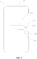
- FIG. 1 is a diagram of a structure of electronic equipment according to an exemplary embodiment herein.
- electronic equipment 1 includes an equipment body 11 and a magnetic sensor apparatus 12 assembled to the equipment body 11.
- the magnetic sensor apparatus 12 includes a control circuit 122 and at least two magnetic field detectors 121. Any two magnetic field detectors 121 sense a magnetic field respectively in two sensing directions differing from one another.
- the control circuit 122 is conductively connected to a motherboard 111 of the equipment body 11.
- the control circuit 122 sends a sensor signal to the motherboard 111 when each magnetic field detector 121 senses external magnetic induction no less than a preset threshold corresponding to the each magnetic field detector.
- the motherboard 111 sends a control signal to control the equipment body 11 according to the sensor signal.
- the magnetic sensor apparatus 12 is provided with at least two magnetic field detectors 121. Any two magnetic field detectors 121 sense a magnetic field respectively in two different sensing directions.
- the control circuit 122 sends a sensor signal to the motherboard 111 only when each magnetic field detector 121 senses, in a respective sensing direction, external magnetic induction no less than a respective preset threshold corresponding to the each magnetic field detector.
- the motherboard 111 sends a control signal to control the equipment body 11 according to the sensor signal. Therefore, by monitoring magnetic induction in multiple directions, precision in sensing by the magnetic sensor apparatus 12 is improved, avoiding inadvertent trigger of a function of electronic equipment 1 caused by interference to monitoring of magnetic field intensity in but one direction.
- an external magnetic field associated with the magnetic sensor apparatus 12 may come from external equipment used in coordination with the electronic equipment 1, a protective case 2 used in coordination with the electronic equipment 1, etc.
- a magnetic part 211 located in the external equipment may generate magnetic induction with each component in a sensing direction of a respective magnetic field detector 121 of the electronic equipment 1 reaching a corresponding preset threshold. Then, the electronic equipment 1 may be triggered to start a corresponding function.
- a magnetic part 211 on the cover may generate magnetic induction with each component in a sensing direction of a respective magnetic field detector 121 of the electronic equipment 1 reaching a corresponding preset threshold. Then, the motherboard 111 of the electronic equipment 1 may receive a sensor signal and control to turn off the screen.
- the motherboard 111 of the electronic equipment 1 may control to light up the screen for once.
- the magnetic sensor apparatus 12 may be provided in an edge region of the equipment body 11, thus reducing interference to the magnetic sensor apparatus 12 by a magnetic field generated by an electromagnetic component or a circuit internal to the electronic equipment 1, improving sensing precision and sensitivity of the magnetic sensor apparatus 12.
- the magnetic sensor apparatus 12 may include two, three or more magnetic field detectors 121, as required by a specific circumstance to which the magnetic sensor apparatus 12 applies. Sensing directions and judgment precision of the magnetic sensor apparatus 12 may be increased by increasing the number of magnetic field detectors 121. Cost, complexity of the structure, etc., of the magnetic sensor apparatus 12 may be reduced by decreasing the number of magnetic field detectors 121, and no limit thereto is set herein.
- the magnetic sensor apparatus 12 may be provided with two magnetic field detectors 121, as shown in exemplary description as follows.
- At least two magnetic field detectors 121 may sense the magnetic field respectively in two sensing directions perpendicular to one another.
- the magnetic sensor apparatus 12 may be provided with two magnetic field detectors 121.
- the two magnetic field detectors 121 may sense the magnetic field respectively in two sensing directions perpendicular to one another.
- the magnetic sensor apparatus 12 may be provided with three magnetic field detectors 121.
- the three magnetic field detectors 121 may sense the magnetic field respectively in three sensing directions each two of which are perpendicular to one another. Providing magnetic field detectors 121 with sensing directions perpendicular to one another is easy, and allows reasonable distribution of the sensing directions of the magnetic field detectors 121, improving utilization of each magnetic field detector 121.
- At least one magnetic field detector 121 may sense the magnetic field in a sensing direction along a thickness of the electronic equipment 1, to sense and determine magnetic induction in the direction along the thickness the electronic equipment 1. For example, based on how a tablet is commonly held, operated, used, etc., there may generally be a component of magnetic induction of an external magnetic field in a direction along a thickness of the tablet. It may be appropriate to determine whether the component of magnetic induction in the direction along the thickness is no less than a preset threshold corresponding to that direction.
- the magnetic sensor apparatus 12 may include one or more magnetic sensors.
- a magnetic sensor may be a separate integral sensor device such as a Hall magnetic sensor, an Anisotropic Magneto Resistance (AMR) magnetic sensor (which is a magnetic sensor that implements detection using a change in reluctance brought about by the magnetic field in a specific direction), a Giant Magneto Resistive (GMR) magnetic sensor, etc.
- AMR Anisotropic Magneto Resistance
- GMR Giant Magneto Resistive
- Such a magnetic sensor may also be a chip serving to sense the magnetic field in at least one sensing direction. No limit to the form of a magnetic sensor is set herein.
- the magnetic sensor apparatus 12 may include one magnetic sensor.
- the magnetic sensor apparatus 12 may be a Hall magnetic sensor, an AMR magnetic sensor, or a GMR magnetic sensor.
- the magnetic sensor may include at least two magnetic field detectors 121 with different sensing directions to monitor magnetic induction in different directions, simplifying the structure of the magnetic sensor apparatus 12, improving integration of functions of the magnetic sensor apparatus 12, reducing space occupied by the electronic equipment 1.
- the magnetic sensor apparatus 12 may include multiple magnetic sensors. Each magnetic sensor may be provided with at least one magnetic field detector 121. Magnetic induction in different directions may be monitored through association and coordination between the multiple magnetic sensors, improving flexibility in arrangement of the magnetic field detector(s) 121, facilitating assembly and coordination.
- electronic equipment A may be equipped with a protective case B.
- a magnet B1 may in general be provided on the protective case B.
- Smart lighting-up and/or turning-off of a screen A2 of the electronic equipment A may be implemented using a change in a magnetic field sensed by a magnetic sensor apparatus A1 at opening and/or closing of the protective case B.
- the changing location of the magnet B1 at opening and/or closing of the protective case B may complicate circumstance of the magnetic field in the sensing direction of the magnetic sensor apparatus A1, which may cause a misjudgment by the magnetic sensor apparatus A1, thereby causing inadvertent trigger of the screen A2 of the electronic equipment.
- FIG. 2A, FIG. 2B , FIG. 3A, and FIG. 3B show two states in use.
- a cover B2 of the protective case is closed.
- the cover B2 of the protective case is open and folded to the back of the electronic equipment A.
- Dashed arrows in the figures schematically show the magnetic field the magnet B1 applies to the magnetic sensor apparatus A1.
- the thin solid arrow in the magnet B1 indicates the direction of the magnetic field inside the magnet B1.
- the thick solid arrow on the magnetic sensor apparatus A1 indicates the sensing direction of the magnetic sensor apparatus A1.
- Magnetic induction sensed by the magnetic sensor apparatus A1 in the direction along the thickness of the electronic equipment A when the cover B2 of the protective case is closed is the same as that sensed by the magnetic sensor apparatus A1 in the direction along the thickness of the electronic equipment A when the cover B2 of the protective case is open and folded to the back of the electronic equipment A, thus causing inadvertent trigger of turning-off of the screen A2.
- FIG. 4 is a diagram of a sectional structure of a system for protecting electronic equipment according to an exemplary embodiment herein, with a protective case thereof being in a closed state.
- FIG. 5 is a diagram of a sectional structure of a system for protecting electronic equipment according to an exemplary embodiment herein, with a protective case thereof being in an open state.
- the system for protecting electronic equipment 1 includes a protective case 2 and the electronic equipment 1.
- the protective case 2 includes a movable cover 21.
- the electronic equipment 1 is assembled in the protective case 2.
- the movable cover 21 is in a state including a closed state and an open state.
- the movable cover 21 in the closed state covers a preset side of the equipment body 11.
- dashed arrows may represent magnetic induction lines applied to the magnetic sensor apparatus 12.
- the thin solid arrow in a magnetic part 211 may indicate the direction of the magnetic field inside the magnetic part 211.
- the thick solid arrows on the magnetic sensor apparatus 12 may indicate the sensing directions of the two magnetic field detectors 121 of the magnetic sensor apparatus 12.
- the movable cover 21 in the open state is away from the preset side of the equipment body 11.
- the magnetic part 211 is provided at a location of the movable cover 21 corresponding to the magnetic sensor apparatus.
- a magnetic induction of a magnetic field of the magnetic part 211 in a sensing direction of each magnetic field detector 121 is no less than the preset threshold corresponding to the each magnetic field detector when the movable cover 21 is in the closed state.
- the magnetic induction of the magnetic field of the magnetic part 211 in a sensing direction of at least one magnetic field detector 121 is less than the preset threshold corresponding to the at least one magnetic field detector when the movable cover 21 is in the open state.
- the magnetic sensor apparatus 12 includes at least two magnetic field detectors 121.
- the at least two magnetic field detectors 121 sense a magnetic field respectively in different sensing directions.
- a control circuit 122 sends a sensor signal to a motherboard 111 when a magnetic part 211 located on a protective case 2 applies, to each magnetic field detector 121 in a respective sensing direction of the each magnetic field detector, magnetic induction no less than a preset threshold corresponding to the each magnetic field detector.
- the motherboard 111 sends a control signal to control the equipment body 11 according to the sensor signal.
- the magnetic part 211 may apply its magnetic field to a different location when a movable cover 21 of the protective case 2 is flipped.
- the magnetic part 211 may be provided as follows.
- the magnetic field internal to the magnetic part 21 may be oriented at a preset angle to a sensing direction of any magnetic field detector 121 when the movable cover 21 is in the closed state. Based on the way in which the magnetic part 211 is provided, when the movable cover 21 is in the closed state, there may be components of the magnetic field of the magnetic part 211 in sensing directions of at least two magnetic field detectors 121. By determining whether values of magnetic induction in both sensing directions are no less than the preset thresholds, precision in sensing by the magnetic sensor apparatus 12 may be improved, avoiding inadvertent trigger by a magnetic field caused by a change in the location of the movable cover 21.
- the preset angle may be an acute angle, an obtuse angle, or a right angle, and no limit thereto is set herein.
- the magnetic field internal to the magnetic part 211 may be oriented parallel to a sensing direction of any magnetic field detector 121 when the movable cover 21 is in the closed state.
- the location of the magnetic part 211 may deviate from that of the magnetic field detector 121 in a parallel direction due to the structure.
- the deviation in the locations may lead to components of magnetic induction of the magnetic field of the magnetic part 211 respectively in at least the sensing direction of the magnetic field detector 121 and the sensing direction of a second magnetic field detector 121 perpendicular to the sensing direction of the magnetic field detector 121.
- the magnetic part 211 may be provided inside the movable cover 21.
- the magnetic part may be embedded inside or outside the movable cover 21. No limit thereto is set herein.
- the magnetic part 211 may be a bar magnet, a horseshoe magnet, a cylindrical magnet, etc. No limit thereto is set herein.
- the magnetic part 211 may be a bar magnet.
- the magnetic sensor apparatus 12 of electronic equipment 1 may include two magnetic field detectors 121.
- the two magnetic field detectors 121 may sense the magnetic field respectively in two sensing directions perpendicular to one another.
- one magnetic field detector 121 may sense the magnetic field in the direction along the thickness the electronic equipment 1.
- the magnetic field inside the bar magnet may be parallel or perpendicular to the direction along the thickness of the electronic equipment 1.
- the magnetic field internal to the bar magnet may be oriented parallel to the direction along the thickness of the electronic equipment 1.
- the magnetic field internal to the bar magnet may be oriented parallel to the sensing direction of one magnetic field detector 121.
- the sensing direction of the one magnetic field detector 121 may be along the thickness of the electronic equipment 1. That is, an axis of the bar magnet along the magnetic field internal to the bar magnet may deviate, by a distance, from an axis of the magnetic field detector 121 along the sensing direction perpendicular to the thickness of the electronic equipment 1.
- the deviate distance may lead to components of magnetic induction of the magnetic field of the bar magnet respectively in at least the sensing direction of the magnetic field detector 121 and the sensing direction of the other magnetic field detector 121 perpendicular to the sensing direction of the magnetic field detector 121.
- the magnetic field internal to the bar magnet may be oriented perpendicular to the direction along the thickness of the electronic equipment 1.
- An axis of the bar magnet perpendicular to the magnetic field internal to the bar magnet may be oriented parallel to the sensing direction of one magnetic field detector 121.
- the sensing direction of the one magnetic field detector 121 may be along the thickness the electronic equipment 1. That is, the axis of the bar magnet perpendicular to the magnetic field internal to the bar magnet may deviate, by a distance, from an axis of the magnetic field detector 121 along the sensing direction perpendicular to the thickness of the electronic equipment 1.
- the magnetic sensor apparatus 12 may include two magnetic field detectors 121. In FIG.
- dashed arrows may represent magnetic induction lines applied to the magnetic sensor apparatus 12.
- the thin solid arrows in the magnetic part 211 may indicate the direction of the magnetic field internal to the magnetic part 211.
- the thick solid arrows on the magnetic sensor apparatus 12 may indicate the sensing directions of the two magnetic field detectors 121 of the magnetic sensor apparatus 12.
- the magnetic sensor apparatus 12 may include two magnetic field detectors 121. As shown in FIG. 7 , dashed arrows may represent magnetic induction lines applied to the magnetic sensor apparatus 12.
- the thin solid arrows in the magnetic part 211 may indicate the direction of the magnetic field internal to the magnetic part 211.
- the thick solid arrows on the magnetic sensor apparatus 12 may indicate the sensing directions of the two magnetic field detectors 121 of the magnetic sensor apparatus 12.
- An axis of the magnetic part 211 along the magnetic field internal to the magnetic part may coincide with an axis of any one magnetic field detector 121 along a sensing direction of the any one magnetic field detector when the movable cover 21 is in the closed state.
- the axis of the magnetic part 211 along the magnetic field internal to the magnetic part coincides with the axis of any one magnetic field detector 121 along the sensing direction of the any one magnetic field detector, with at least two magnetic field detectors 121 of different sensing directions, it may still be determined whether magnetic induction is no less than a preset threshold using a magnetic field detector 121 of another sensing direction, thereby improving precision in sensing by the magnetic sensor apparatus 12, avoiding inadvertent trigger caused by a change in the location of the movable cover 21.
- the magnetic part 211 may be a bar magnet, a horseshoe magnet, a cylindrical magnet, etc. No limit thereto is set herein.
- the electronic equipment 1 may include multiple magnetic sensor apparatuses 12.
- the movable cover 21 may be provided with multiple magnetic parts 211.
- the multiple magnetic parts 211 may be in one-to-one correspondence with the magnetic sensor apparatuses 12.
- the multiple magnetic sensor apparatuses 12 may serve different sensing functions, respectively.
- the multiple magnetic sensor apparatuses may as well be associated with one another to implement one sensing function. No limit thereto is set herein.
- the multiple magnetic sensor apparatuses 12 may serve different sensing functions respectively, enriching functionality of the electronic equipment 1.
- the multiple magnetic sensor apparatuses 12 may be associated with one another to implement one sensing function, improving precision of the sensing function, avoiding inadvertent trigger, etc.
- the electronic equipment 1 may be a mobile phone, an on-board user equipment, a tablet computer, a medical user equipment, etc. No limit thereto is set herein.
- the electronic equipment includes an equipment body and a magnetic sensor apparatus assembled to the equipment body.
- the magnetic sensor apparatus includes a control circuit and at least two magnetic field detectors. Any two of the at least two magnetic field detectors sense a magnetic field respectively in two sensing directions differing from one another.
- the control circuit is conductively connected to a motherboard of the equipment body.
- the control circuit sends a sensor signal to the motherboard in response to determining that external magnetic induction sensed by each of the at least two magnetic field detectors is no less than a preset threshold corresponding to the each of the at least two magnetic field detectors.
- the motherboard sends a control signal to control the equipment body according to the sensor signal.
- a computer-readable storage medium has stored thereon instructions that, when executed by a processor 820, cause the processor 820 to implement at least part of the method.
- a computer program includes instructions for executing at least part of the method when said program is executed by a computer.
- FIG. 8 is a diagram of a structure of electronic equipment according to an exemplary embodiment herein.
- the electronic equipment 800 may be a mobile phone, a computer, a digital broadcast UE, a messaging device, a gaming console, a tablet, a medical device, exercise equipment, a personal digital assistant, etc.
- the electronic equipment 800 may include at least one of a processing component 802, memory 804, a power component 806, a multimedia component 808, an audio component 810, an Input / Output (I / O) interface 812, a sensor component 814, or a communication component 816.
- a processing component 802 memory 804
- a power component 806 a multimedia component 808, an audio component 810, an Input / Output (I / O) interface 812, a sensor component 814, or a communication component 816.
- I / O Input / Output
- the processing component 802 may generally control an overall operation of the electronic equipment 800, such as operations associated with display, a telephone call, data communication, a camera operation, a recording operation, etc.
- the processing component 802 may include one or more processors 820 to execute instructions so as to complete all or a part of an aforementioned method.
- the processing component 802 may include one or more portions to facilitate interaction between the processing component 802 and other components.
- the processing component 802 may include a multimedia portion to facilitate interaction between the multimedia component 808 and the processing component 802.
- the memory 804 may be adapted to storing various types of data to support the operation at the electronic equipment 800. Examples of such data may include instructions of any application or method adapted to operating on the electronic equipment 800, contact data, phonebook data, messages, pictures, videos, etc.
- the memory 804 may be realized by any type of transitory or non-transitory storage equipment or a combination thereof, such as Static Random Access Memory (SRAM), Electrically Erasable Programmable Read-Only Memory (EEPROM), Erasable Programmable Read-Only Memory (EPROM), Programmable Read-Only Memory (PROM), Read-Only Memory (ROM), magnetic memory, flash memory, a magnetic disk, a compact disk, etc.
- SRAM Static Random Access Memory
- EEPROM Electrically Erasable Programmable Read-Only Memory
- EPROM Erasable Programmable Read-Only Memory
- PROM Programmable Read-Only Memory
- ROM Read-Only Memory
- magnetic memory flash memory, a magnetic disk, a compact disk, etc.
- the power component 806 may supply electric power to various components of the electronic equipment 800.
- the power component 806 may include a power management system, one or more power sources, and other components related to generating, managing, and distributing electricity for the electronic equipment 800.
- the multimedia component 808 may include a screen that provides an output interface between the electronic equipment 800 and a user.
- the screen may include a Liquid Crystal Display (LCD), a Touch Panel (TP), etc. If the screen includes a TP, the screen may be realized as a touch screen to receive a signal input by a user.
- the TP may include one or more touch sensors for sensing touch, slide, and gestures on the TP. The one or more touch sensors not only may sense the boundary of a touch or slide move, but also detect the duration and pressure related to the touch or slide move.
- the multimedia component 808 may include at least one of a front camera or a rear camera.
- At least one of the front camera or the rear camera may receive external multimedia data.
- Each of the front camera or the rear camera may be a fixed optical lens system or may have a focal length and be capable of optical zooming.
- the audio component 810 may be adapted to outputting and / or inputting an audio signal.
- the audio component 810 may include a microphone (MIC).
- the MIC may be adapted to receiving an external audio signal.
- the received audio signal may be further stored in the memory 804 or may be sent via the communication component 816.
- the audio component 810 may further include a loudspeaker adapted to outputting the audio signal.
- the I / O interface 812 may provide an interface between the processing component 802 and a peripheral interface portion.
- a peripheral interface portion may be a keypad, a click wheel, a button, etc.
- a button may include but is not limited to at least one of a homepage button, a volume button, a start button, or a lock button.
- the sensor component 814 may include one or more sensors for assessing various states of the electronic equipment 800. For example, the sensor component 814 may detect an on/off state of the electronic equipment 800 and relative positioning of components such as the display and the keypad of the electronic equipment 800. The sensor component 814 may further detect a change in the position of the electronic equipment 800 or of a component of the electronic equipment 800, whether there is contact between the electronic equipment 800 and a user, the orientation or acceleration / deceleration of the electronic equipment 800, a change in the temperature of the electronic equipment 800, etc.
- the sensor component 814 may include a proximity sensor adapted to detecting existence of a nearby object without physical contact.
- the sensor component 814 may further include an optical sensor such as a Complementary Metal-Oxide-Semiconductor (CMOS) or a Charge-Coupled-Device (CCD) image sensor used in an imaging application.
- CMOS Complementary Metal-Oxide-Semiconductor
- CCD Charge-Coupled-Device
- the sensor component 814 may further include an acceleration sensor, a gyroscope sensor, a magnetic sensor, a pressure sensor, a temperature sensor, etc.
- the communication component 816 may be adapted to facilitating wired or wireless communication between the electronic equipment 800 and other equipment.
- the electronic equipment 800 may access a wireless network based on a communication standard such as Wi-Fi, 2G, 3G..., or a combination thereof.
- the communication component 816 may broadcast related information or receive a broadcast signal from an external broadcast management system via a broadcast channel.
- the communication component 816 may include a Near Field Communication (NFC) portion for short-range communication.
- the NFC portion may be based on technology such as Radio Frequency Identification (RFID), Infrared Data Association (IrDA), Ultra-Wideband (UWB) technology, Bluetooth (BT), etc.
- RFID Radio Frequency Identification
- IrDA Infrared Data Association
- UWB Ultra-Wideband
- Bluetooth Bluetooth
- the electronic equipment 800 may be realized by one or more electronic components such as an Application Specific Integrated Circuit (ASIC), a Digital Signal Processor (DSP), a Digital Signal Processing Device (DSPD), a Programmable Logic Device (PLD), a Field Programmable Gate Array (FPGA), a controller, a microcontroller, a microprocessor, etc., to implement an aforementioned method.
- ASIC Application Specific Integrated Circuit
- DSP Digital Signal Processor
- DSPD Digital Signal Processing Device
- PLD Programmable Logic Device
- FPGA Field Programmable Gate Array
- a transitory or non-transitory computer-readable storage medium including instructions, such as memory 804 including instructions, may be provided.
- the instructions may be executed by the processor 820 of the electronic equipment 800 to implement an aforementioned method.
- the transitory or non-transitory computer-readable storage medium may be Read-Only Memory (ROM), Random Access Memory (RAM), Compact Disc Read-Only Memory (CD-ROM), a magnetic tape, a floppy disk, optical data storage equipment, etc.
- the processor may be a Central Processing Unit (CPU), a general purpose processor, a Digital Signal Processor (DSP), an Application Specific Integrated Circuit (ASIC), and/or the like.
- a general purpose processor may be a microprocessor, any conventional processor, and/or the like.
- Aforementioned memory may be a Read-Only Memory (ROM), a Random Access Memory (RAM), a flash memory, a hard disk, a solid state disk, and/or the like.
- SIM Subscriber Identity Module
- a smart card may have to be installed on a digital mobile phone before the phone can be used.
- Content such as information on a user of the digital mobile phone, an encryption key, a phonebook of the user, may be stored on the computer chip.
- An option of the method according to any combination of embodiments herein may be executed by a hardware processor, or by a combination of hardware and software modules in the processor.
- multiple it may mean two or more.
- a term “and/or” may describe an association between associated objects, including three possible relationships.
- a and /or B it may mean that there may be three cases, namely, existence of but A, existence of both A and B, or existence of but B.
- a slash mark "/” may generally denote an "or" relationship between two associated objects that come respectively before and after the mark per se.
Landscapes
- Engineering & Computer Science (AREA)
- Physics & Mathematics (AREA)
- Theoretical Computer Science (AREA)
- General Physics & Mathematics (AREA)
- General Engineering & Computer Science (AREA)
- Computer Hardware Design (AREA)
- Human Computer Interaction (AREA)
- Condensed Matter Physics & Semiconductors (AREA)
- Automation & Control Theory (AREA)
- Electromagnetism (AREA)
- Telephone Set Structure (AREA)
Abstract
Description
- The subject disclosure relates to the field of electronics, and in particular to electronic equipment, a system for protecting electronic equipment, a method for controlling electronic equipment, a storage medium, and a computer program.
- In related art, electronic equipment such as a mobile phone or a tablet may be provided with a magnetic sensor apparatus. The magnetic sensor apparatus may monitor information on an external magnetic field in a designated direction and perform smart trigger of a related function of the electronic equipment. However, a magnetic sensor apparatus that monitors information on a magnetic field in but one direction may be susceptible to interference from an internal magnetic field, an external magnetic field, etc., leading to inadvertent trigger of a related function of the electronic equipment.
- Electronic equipment may be equipped with a protective case. A magnet may in general be provided on the protective case. Smart lighting-up and/orturning-off of a screen of the electronic equipment may be implemented using a change in a magnetic field sensed by a magnetic sensor apparatus at opening and/or closing of the protective case. Complicatedness of the change in the magnetic field at opening and/or closing of the protective case may cause a misjudgment by the magnetic sensor apparatus, which often causes inadvertent trigger of the screen of the electronic equipment.
- The subject disclosure provides electronic equipment, a system for protecting electronic equipment, a method for controlling electronic equipment, a storage medium, and a computer program, capable of improving a precision in sensing by a magnetic sensor apparatus in the electronic equipment, avoiding inadvertent trigger of a function of the electronic equipment, improving experience in using a protective case in the system for protecting electronic equipment.
- Other features and advantages of embodiments herein may become clear with elaboration made below, or may be learned partially by practicing embodiments herein.
- According to an aspect of the subject disclosure, electronic equipment includes an equipment body and a magnetic sensor apparatus assembled to the equipment body. The magnetic sensor apparatus includes a control circuit and at least two magnetic field detectors.
- Any two of the at least two magnetic field detectors sense a magnetic field respectively in two sensing directions differing from one another.
- The control circuit is conductively connected to a motherboard of the equipment body. The control circuit sends a sensor signal to the motherboard in response to determining that external magnetic induction sensed by each of the at least two magnetic field detectors is no less than a preset threshold corresponding to the each of the at least two magnetic field detectors. The motherboard sends a control signal to control the equipment body according to the sensor signal.
- With embodiments herein, a magnetic sensor apparatus is provided with at least two magnetic field detectors. Any two magnetic field detectors sense a magnetic field respectively in two different sensing directions. A control circuit sends a sensor signal to a motherboard only when each magnetic field detector senses, in a respective sensing direction per se, external magnetic induction no less than a respective preset threshold corresponding to the each magnetic field detector. The motherboard sends a control signal to control an equipment body according to the sensor signal. Therefore, by monitoring magnetic induction in multiple directions, precision in sensing by the magnetic sensor apparatus is improved, avoiding inadvertent trigger of a function of electronic equipment caused by monitoring of magnetic field intensity in but one direction.
- Optionally, at least two of the at least two magnetic field detectors may sense the magnetic field respectively in two sensing directions perpendicular to one another.
- Optionally, at least one of the at least two magnetic field detectors may sense the magnetic field in a sensing direction along a thickness of the electronic equipment.
- Optionally, the magnetic sensor apparatus may be a Hall magnetic sensor, an Anisotropic Magneto Resistance (AMR) magnetic sensor, or a Giant Magneto Resistive (GMR) magnetic sensor.
- Optionally, the magnetic sensor apparatus may include multiple magnetic sensors. Each of the multiple magnetic sensors may be provided with at least one of the at least two magnetic field detectors.
- Optionally, the magnetic sensor apparatus may be provided in an edge region of the equipment body.
- According to an aspect of the subject disclosure, a system for protecting electronic equipment may include a protective case and the electronic equipment.
- The protective case may include a movable cover. The electronic equipment may be assembled in the protective case. The movable cover may be in a state including a closed state and an open state. The movable cover in the closed state may cover a preset side of the equipment body. The movable cover in the open state may be away from the preset side of the equipment body.
- A magnetic part may be provided at a location of the movable cover corresponding to the magnetic sensor apparatus. Magnetic induction of a magnetic field of the magnetic part in a sensing direction of the each of the at least two magnetic field detectors may be no less than the preset threshold corresponding to the each of the at least two magnetic field detectors in response to the movable cover being in the closed state. The magnetic induction of the magnetic field of the magnetic part in a sensing direction of at least one of the at least two magnetic field detectors may be less than the preset threshold corresponding to the at least one of the at least two magnetic field detectors in response to the movable cover being in the open state.
- Experience in using a protective case of the electronic equipment may be improved as well when the magnetic sensor apparatus and trigger of a function of the electronic equipment are controlled through a magnetic field of a magnetic part coordinated on the protective case.
- Optionally, the magnetic field internal to the magnetic part may be oriented at a preset angle to a sensing direction of any of the at least two magnetic field detectors in response to the movable cover being in the closed state.
- Optionally, the magnetic field internal to the magnetic part may be oriented parallel to a sensing direction of any one of the at least two magnetic field detectors in response to the movable cover being in the closed state.
- Optionally, the magnetic part may be a bar magnet. A magnetic field internal to the bar magnet may be oriented parallel or perpendicular to a direction along a thickness of the electronic equipment.
- Optionally, an axis of the magnetic part along the magnetic field internal to the magnetic part may coincide with an axis of any one of the at least two magnetic field detectors along a sensing direction of the any one of the at least two magnetic field detectors in response to the movable cover being in the closed state.
- Optionally, the electronic equipment may include a plurality of the magnetic sensor apparatuses. The movable cover may be provided with a plurality of the magnetic parts in one-to-one correspondence with the magnetic sensor apparatuses.
- A method for controlling electronic equipment is provided according to an aspect of the subject disclosure. The electronic equipment includes an equipment body and a magnetic sensor apparatus assembled to the equipment body. The magnetic sensor apparatus includes a control circuit and at least two magnetic field detectors. Any two of the at least two magnetic field detectors sense a magnetic field respectively in two sensing directions differing from one another. The control circuit is conductively connected to a motherboard of the equipment body. The method includes options as follows.
- The control circuit sends a sensor signal to the motherboard in response to determining that external magnetic induction sensed by each of the at least two magnetic field detectors is no less than a preset threshold corresponding to the each of the at least two magnetic field detectors.
- The motherboard sends a control signal to control the equipment body according to the sensor signal.
- The advantages and technical effects of the method herein correspond to those of the electronic equipment presented above.
- According to an aspect of the subject disclosure, a transitory or non-transitory computer-readable storage medium / information medium has stored thereon a computer-executable instruction of a computer program that, when executed by a processor of electronic equipment, cause the electronic equipment to implement at least part of any aforementioned method.
- The information medium can be any entity or device capable of storing the program. For example, the support can include storage means such as a ROM, for example a CD ROM or a microelectronic circuit ROM, or magnetic storage means, for example a diskette (floppy disk) or a hard disk.
- Alternatively, the information medium can be an integrated circuit in which the program is incorporated, the circuit being adapted to execute the method in question or to be used in its execution.
- The options of the method may be determined by computer program instructions.
- Consequently, according to an aspect herein, the subject disclosure is further directed to a computer program for executing the options of the method as described above when this program is executed by a computer.
- This program can use any programming language and take the form of source code, object code or a code intermediate between source code and object code, such as a partially compiled form, or any other desirable form.
- The above general description and elaboration below are but exemplary and explanatory, and do not limit the subject disclosure.
- Drawings here are incorporated in and constitute part of the subject specification, illustrate embodiments according to the subject disclosure, and together with the subject specification, serve to explain the principle of the subject disclosure.
-
FIG. 1 is a diagram of a structure of electronic equipment according to an exemplary embodiment herein. -
FIG. 2A is a diagram of a sectional structure of a system for protecting electronic equipment in related art, with a protective case thereof being in a closed state. -
FIG. 2B is a close up view of a part a-a inFIG. 2A . -
FIG. 3A is a diagram of a sectional structure of a system for protecting electronic equipment in related art, with a protective case thereof being in an open state. -
FIG. 3B is a close up view of a part b-b inFIG. 3A . -
FIG. 4 is a diagram of a sectional structure of a system for protecting electronic equipment according to an exemplary embodiment herein, with a protective case thereof being in a closed state. -
FIG. 5 is a diagram of a sectional structure of a system for protecting electronic equipment according to an exemplary embodiment herein, with a protective case thereof being in an open state. -
FIG. 6 is a diagram of a sectional structure of a system for protecting electronic equipment according to an exemplary embodiment herein, with a protective case thereof being in a closed state. -
FIG. 7 is a diagram of a sectional structure of a system for protecting electronic equipment according to an exemplary embodiment herein, with a protective case thereof being in a closed state. -
FIG. 8 is a diagram of a structure of electronic equipment according to an exemplary embodiment herein. - Exemplary embodiments (examples of which are illustrated in the accompanying drawings) are elaborated below. The following description refers to the accompanying drawings, in which identical or similar elements in two drawings are denoted by identical reference numerals unless indicated otherwise. Implementations set forth in the following exemplary embodiments do not represent all implementations in accordance with the subject disclosure. Rather, they are merely examples of the apparatus and method in accordance with certain aspects herein as recited in the accompanying claims. The exemplary implementation modes may take on multiple forms, and should not be taken as being limited to examples illustrated herein. Instead, by providing such implementation modes, embodiments herein may become more comprehensive and complete, and comprehensive concept of the exemplary implementation modes may be delivered to those skilled in the art. Implementations set forth in the following exemplary embodiments do not represent all implementations in accordance with the subject disclosure. Rather, they are merely examples of the apparatus and method in accordance with certain aspects herein as recited in the accompanying claims.
- Aterm used in an embodiment herein is merely for describing the embodiment instead of limiting the subject disclosure. A singular form "a" and "the" used in an embodiment herein and the appended claims may also be intended to include a plural form, unless clearly indicated otherwise by context. Further note that a term "and / or" used herein may refer to and contain any combination or all possible combinations of one or more associated listed items.
- Note that although a term such as first, second, third may be adopted in an embodiment herein to describe various kinds of information, such information should not be limited to such a term. Such a term is merely for distinguishing information of the same type. For example, without departing from the scope of the embodiments herein, the first information may also be referred to as the second information. Similarly, the second information may also be referred to as the first information. Depending on the context, a "if" as used herein may be interpreted as "when" or "while" or "in response to determining that".
- In addition, described characteristics, structures or features may be combined in one or more implementation modes in any proper manner. In the following descriptions, many details are provided to allow a full understanding of embodiments herein. However, those skilled in the art will know that the technical solutions of embodiments herein may be carried out without one or more of the details; alternatively, another method, component, device, option, etc., may be adopted. Under other conditions, no detail of a known structure, method, device, implementation, material or operation may be shown or described to avoid obscuring aspects of embodiments herein.
- A block diagram shown in the accompanying drawings may be a functional entity which may not necessarily correspond to a physically or logically independent entity. Such a functional entity may be implemented in form of software, in one or more hardware modules or integrated circuits, or in different networks and /or processor devices and /or microcontroller devices.
- In related art, electronic equipment such as a mobile phone or a tablet may be provided with a magnetic sensor apparatus. The magnetic sensor apparatus may monitor information on an external magnetic field in a designated direction and perform smart trigger of a related function of the electronic equipment. However, a magnetic sensor apparatus that monitors information on a magnetic field in but one direction may be susceptible to interference from an internal magnetic field, an external magnetic field, etc., leading to inadvertent trigger of a related function of the electronic equipment.
-
FIG. 1 is a diagram of a structure of electronic equipment according to an exemplary embodiment herein. As shown inFIG. 1 ,electronic equipment 1 includes anequipment body 11 and amagnetic sensor apparatus 12 assembled to theequipment body 11. Themagnetic sensor apparatus 12 includes acontrol circuit 122 and at least twomagnetic field detectors 121. Any twomagnetic field detectors 121 sense a magnetic field respectively in two sensing directions differing from one another. Thecontrol circuit 122 is conductively connected to amotherboard 111 of theequipment body 11. Thecontrol circuit 122 sends a sensor signal to themotherboard 111 when eachmagnetic field detector 121 senses external magnetic induction no less than a preset threshold corresponding to the each magnetic field detector. Themotherboard 111 sends a control signal to control theequipment body 11 according to the sensor signal. - The
magnetic sensor apparatus 12 is provided with at least twomagnetic field detectors 121. Any twomagnetic field detectors 121 sense a magnetic field respectively in two different sensing directions. Thecontrol circuit 122 sends a sensor signal to themotherboard 111 only when eachmagnetic field detector 121 senses, in a respective sensing direction, external magnetic induction no less than a respective preset threshold corresponding to the each magnetic field detector. Themotherboard 111 sends a control signal to control theequipment body 11 according to the sensor signal. Therefore, by monitoring magnetic induction in multiple directions, precision in sensing by themagnetic sensor apparatus 12 is improved, avoiding inadvertent trigger of a function ofelectronic equipment 1 caused by interference to monitoring of magnetic field intensity in but one direction. - In the embodiment, an external magnetic field associated with the
magnetic sensor apparatus 12 may come from external equipment used in coordination with theelectronic equipment 1, aprotective case 2 used in coordination with theelectronic equipment 1, etc. - For example, when the external equipment is at a location in a relation to the location of the electronic equipment that satisfies a preset condition, a
magnetic part 211 located in the external equipment may generate magnetic induction with each component in a sensing direction of a respectivemagnetic field detector 121 of theelectronic equipment 1 reaching a corresponding preset threshold. Then, theelectronic equipment 1 may be triggered to start a corresponding function. - In another example, when a cover of the
protective case 2 is closed, amagnetic part 211 on the cover may generate magnetic induction with each component in a sensing direction of a respectivemagnetic field detector 121 of theelectronic equipment 1 reaching a corresponding preset threshold. Then, themotherboard 111 of theelectronic equipment 1 may receive a sensor signal and control to turn off the screen. On the other hand, when theprotective case 2 is open, magnetic induction in the sensing direction of at least onemagnetic field detector 121 is less than a corresponding preset threshold thereto, themotherboard 111 of theelectronic equipment 1 may control to light up the screen for once. - In the embodiment, the
magnetic sensor apparatus 12 may be provided in an edge region of theequipment body 11, thus reducing interference to themagnetic sensor apparatus 12 by a magnetic field generated by an electromagnetic component or a circuit internal to theelectronic equipment 1, improving sensing precision and sensitivity of themagnetic sensor apparatus 12. - The
magnetic sensor apparatus 12 may include two, three or moremagnetic field detectors 121, as required by a specific circumstance to which themagnetic sensor apparatus 12 applies. Sensing directions and judgment precision of themagnetic sensor apparatus 12 may be increased by increasing the number ofmagnetic field detectors 121. Cost, complexity of the structure, etc., of themagnetic sensor apparatus 12 may be reduced by decreasing the number ofmagnetic field detectors 121, and no limit thereto is set herein. Themagnetic sensor apparatus 12 may be provided with twomagnetic field detectors 121, as shown in exemplary description as follows. - According to an embodiment, at least two
magnetic field detectors 121 may sense the magnetic field respectively in two sensing directions perpendicular to one another. For example, themagnetic sensor apparatus 12 may be provided with twomagnetic field detectors 121. The twomagnetic field detectors 121 may sense the magnetic field respectively in two sensing directions perpendicular to one another. Alternatively, themagnetic sensor apparatus 12 may be provided with threemagnetic field detectors 121. The threemagnetic field detectors 121 may sense the magnetic field respectively in three sensing directions each two of which are perpendicular to one another. Providingmagnetic field detectors 121 with sensing directions perpendicular to one another is easy, and allows reasonable distribution of the sensing directions of themagnetic field detectors 121, improving utilization of eachmagnetic field detector 121. - Further, at least one
magnetic field detector 121 may sense the magnetic field in a sensing direction along a thickness of theelectronic equipment 1, to sense and determine magnetic induction in the direction along the thickness theelectronic equipment 1. For example, based on how a tablet is commonly held, operated, used, etc., there may generally be a component of magnetic induction of an external magnetic field in a direction along a thickness of the tablet. It may be appropriate to determine whether the component of magnetic induction in the direction along the thickness is no less than a preset threshold corresponding to that direction. - The
magnetic sensor apparatus 12 may include one or more magnetic sensors. Such a magnetic sensor may be a separate integral sensor device such as a Hall magnetic sensor, an Anisotropic Magneto Resistance (AMR) magnetic sensor (which is a magnetic sensor that implements detection using a change in reluctance brought about by the magnetic field in a specific direction), a Giant Magneto Resistive (GMR) magnetic sensor, etc. Such a magnetic sensor may also be a chip serving to sense the magnetic field in at least one sensing direction. No limit to the form of a magnetic sensor is set herein. Themagnetic sensor apparatus 12 may include one magnetic sensor. Themagnetic sensor apparatus 12 may be a Hall magnetic sensor, an AMR magnetic sensor, or a GMR magnetic sensor. The magnetic sensor may include at least twomagnetic field detectors 121 with different sensing directions to monitor magnetic induction in different directions, simplifying the structure of themagnetic sensor apparatus 12, improving integration of functions of themagnetic sensor apparatus 12, reducing space occupied by theelectronic equipment 1. Alternatively, themagnetic sensor apparatus 12 may include multiple magnetic sensors. Each magnetic sensor may be provided with at least onemagnetic field detector 121. Magnetic induction in different directions may be monitored through association and coordination between the multiple magnetic sensors, improving flexibility in arrangement of the magnetic field detector(s) 121, facilitating assembly and coordination. - In related art, electronic equipment A may be equipped with a protective case B. A magnet B1 may in general be provided on the protective case B. Smart lighting-up and/or turning-off of a screen A2 of the electronic equipment A may be implemented using a change in a magnetic field sensed by a magnetic sensor apparatus A1 at opening and/or closing of the protective case B. The changing location of the magnet B1 at opening and/or closing of the protective case B may complicate circumstance of the magnetic field in the sensing direction of the magnetic sensor apparatus A1, which may cause a misjudgment by the magnetic sensor apparatus A1, thereby causing inadvertent trigger of the screen A2 of the electronic equipment. For example,
FIG. 2A, FIG. 2B ,FIG. 3A, and FIG. 3B show two states in use. In one state, a cover B2 of the protective case is closed. In the other state, the cover B2 of the protective case is open and folded to the back of the electronic equipment A. Dashed arrows in the figures schematically show the magnetic field the magnet B1 applies to the magnetic sensor apparatus A1. The thin solid arrow in the magnet B1 indicates the direction of the magnetic field inside the magnet B1. The thick solid arrow on the magnetic sensor apparatus A1 indicates the sensing direction of the magnetic sensor apparatus A1. Magnetic induction sensed by the magnetic sensor apparatus A1 in the direction along the thickness of the electronic equipment A when the cover B2 of the protective case is closed is the same as that sensed by the magnetic sensor apparatus A1 in the direction along the thickness of the electronic equipment A when the cover B2 of the protective case is open and folded to the back of the electronic equipment A, thus causing inadvertent trigger of turning-off of the screen A2. -
FIG. 4 is a diagram of a sectional structure of a system for protecting electronic equipment according to an exemplary embodiment herein, with a protective case thereof being in a closed state.FIG. 5 is a diagram of a sectional structure of a system for protecting electronic equipment according to an exemplary embodiment herein, with a protective case thereof being in an open state. As shown inFIG. 4 andFIG. 5 , the system for protectingelectronic equipment 1 includes aprotective case 2 and theelectronic equipment 1. Theprotective case 2 includes amovable cover 21. Theelectronic equipment 1 is assembled in theprotective case 2. Themovable cover 21 is in a state including a closed state and an open state. Themovable cover 21 in the closed state covers a preset side of theequipment body 11. Considering an example where themagnetic sensor apparatus 12 includes twomagnetic field detectors 121. InFIG. 4 andFIG. 5 , dashed arrows may represent magnetic induction lines applied to themagnetic sensor apparatus 12. The thin solid arrow in amagnetic part 211 may indicate the direction of the magnetic field inside themagnetic part 211. The thick solid arrows on themagnetic sensor apparatus 12 may indicate the sensing directions of the twomagnetic field detectors 121 of themagnetic sensor apparatus 12. Themovable cover 21 in the open state is away from the preset side of theequipment body 11. Themagnetic part 211 is provided at a location of themovable cover 21 corresponding to the magnetic sensor apparatus. A magnetic induction of a magnetic field of themagnetic part 211 in a sensing direction of eachmagnetic field detector 121 is no less than the preset threshold corresponding to the each magnetic field detector when themovable cover 21 is in the closed state. The magnetic induction of the magnetic field of themagnetic part 211 in a sensing direction of at least onemagnetic field detector 121 is less than the preset threshold corresponding to the at least one magnetic field detector when themovable cover 21 is in the open state. -
Electronic equipment 1 and amagnetic sensor apparatus 12 thereof are provided with a structure according to the embodiment, which is not repeated here. Themagnetic sensor apparatus 12 includes at least twomagnetic field detectors 121. The at least twomagnetic field detectors 121 sense a magnetic field respectively in different sensing directions. Acontrol circuit 122 sends a sensor signal to amotherboard 111 when amagnetic part 211 located on aprotective case 2 applies, to eachmagnetic field detector 121 in a respective sensing direction of the each magnetic field detector, magnetic induction no less than a preset threshold corresponding to the each magnetic field detector. Themotherboard 111 sends a control signal to control theequipment body 11 according to the sensor signal. Accordingly, themagnetic part 211 may apply its magnetic field to a different location when amovable cover 21 of theprotective case 2 is flipped. By monitoring magnetic induction in multiple directions, precision in sensing by themagnetic sensor apparatus 12 is improved, avoiding inadvertent trigger of a function ofelectronic equipment 1 caused by monitoring of magnetic field intensity in but one direction, as well as improving experience in using theprotective case 2. - When the
movable cover 21 is in the closed state, precision in sensing by themagnetic sensor apparatus 12 may depend on a relation between the location of themagnetic part 211 and the location of themagnetic sensor apparatus 12, as well as a relation between the orientation of the magnetic field of themagnetic part 211 and the respective sensing direction of eachmagnetic field detector 121. By way of example, themagnetic part 211 may be provided as follows. - According to an embodiment, the magnetic field internal to the
magnetic part 21 may be oriented at a preset angle to a sensing direction of anymagnetic field detector 121 when themovable cover 21 is in the closed state. Based on the way in which themagnetic part 211 is provided, when themovable cover 21 is in the closed state, there may be components of the magnetic field of themagnetic part 211 in sensing directions of at least twomagnetic field detectors 121. By determining whether values of magnetic induction in both sensing directions are no less than the preset thresholds, precision in sensing by themagnetic sensor apparatus 12 may be improved, avoiding inadvertent trigger by a magnetic field caused by a change in the location of themovable cover 21. - The preset angle may be an acute angle, an obtuse angle, or a right angle, and no limit thereto is set herein.
- According to an embodiment, the magnetic field internal to the
magnetic part 211 may be oriented parallel to a sensing direction of anymagnetic field detector 121 when themovable cover 21 is in the closed state. The location of themagnetic part 211 may deviate from that of themagnetic field detector 121 in a parallel direction due to the structure. The deviation in the locations may lead to components of magnetic induction of the magnetic field of themagnetic part 211 respectively in at least the sensing direction of themagnetic field detector 121 and the sensing direction of a secondmagnetic field detector 121 perpendicular to the sensing direction of themagnetic field detector 121. By determining whether values of magnetic induction in both sensing directions are no less than the preset thresholds, precision in sensing by themagnetic sensor apparatus 12 may be improved, avoiding inadvertent trigger caused by a change in the location of themovable cover 21. - The
magnetic part 211 may be provided inside themovable cover 21. The magnetic part may be embedded inside or outside themovable cover 21. No limit thereto is set herein. Themagnetic part 211 may be a bar magnet, a horseshoe magnet, a cylindrical magnet, etc. No limit thereto is set herein. - For example, the
magnetic part 211 may be a bar magnet. Themagnetic sensor apparatus 12 ofelectronic equipment 1 may include twomagnetic field detectors 121. The twomagnetic field detectors 121 may sense the magnetic field respectively in two sensing directions perpendicular to one another. For example, onemagnetic field detector 121 may sense the magnetic field in the direction along the thickness theelectronic equipment 1. The magnetic field inside the bar magnet may be parallel or perpendicular to the direction along the thickness of theelectronic equipment 1. - As shown in
FIG. 4 , the magnetic field internal to the bar magnet may be oriented parallel to the direction along the thickness of theelectronic equipment 1. The magnetic field internal to the bar magnet may be oriented parallel to the sensing direction of onemagnetic field detector 121. The sensing direction of the onemagnetic field detector 121 may be along the thickness of theelectronic equipment 1. That is, an axis of the bar magnet along the magnetic field internal to the bar magnet may deviate, by a distance, from an axis of themagnetic field detector 121 along the sensing direction perpendicular to the thickness of theelectronic equipment 1. When themovable cover 21 is in the closed state, the deviate distance may lead to components of magnetic induction of the magnetic field of the bar magnet respectively in at least the sensing direction of themagnetic field detector 121 and the sensing direction of the othermagnetic field detector 121 perpendicular to the sensing direction of themagnetic field detector 121. By monitoring magnetic induction in both directions, it is ensured that the magnetic field of the bar magnet cannot trigger sending of a sensor signal to themotherboard 111 by themagnetic sensor apparatus 12 no matter where the movable cover is located as long as it is in the open state, avoiding inadvertent trigger of theelectronic equipment 1. - As shown in
FIG. 6 , the magnetic field internal to the bar magnet may be oriented perpendicular to the direction along the thickness of theelectronic equipment 1. An axis of the bar magnet perpendicular to the magnetic field internal to the bar magnet may be oriented parallel to the sensing direction of onemagnetic field detector 121. The sensing direction of the onemagnetic field detector 121 may be along the thickness theelectronic equipment 1. That is, the axis of the bar magnet perpendicular to the magnetic field internal to the bar magnet may deviate, by a distance, from an axis of themagnetic field detector 121 along the sensing direction perpendicular to the thickness of theelectronic equipment 1. For example, themagnetic sensor apparatus 12 may include twomagnetic field detectors 121. InFIG. 6 , dashed arrows may represent magnetic induction lines applied to themagnetic sensor apparatus 12. The thin solid arrows in themagnetic part 211 may indicate the direction of the magnetic field internal to themagnetic part 211. The thick solid arrows on themagnetic sensor apparatus 12 may indicate the sensing directions of the twomagnetic field detectors 121 of themagnetic sensor apparatus 12. When themovable cover 21 is in the closed state, the deviate distance may lead to components of magnetic induction of the magnetic field of the bar magnet respectively in at least the sensing direction of themagnetic field detector 121 and the sensing direction of the othermagnetic field detector 121 perpendicular to the sensing direction of themagnetic field detector 121. By monitoring magnetic induction in both directions, it is ensured that the magnetic field of the bar magnet cannot trigger sending of a sensor signal to themotherboard 111 by themagnetic sensor apparatus 12 no matter where the movable cover is located as long as it is in the open state, avoiding inadvertent trigger of theelectronic equipment 1. - According to an exemplary embodiment, the
magnetic sensor apparatus 12 may include twomagnetic field detectors 121. As shown inFIG. 7 , dashed arrows may represent magnetic induction lines applied to themagnetic sensor apparatus 12. The thin solid arrows in themagnetic part 211 may indicate the direction of the magnetic field internal to themagnetic part 211. The thick solid arrows on themagnetic sensor apparatus 12 may indicate the sensing directions of the twomagnetic field detectors 121 of themagnetic sensor apparatus 12. An axis of themagnetic part 211 along the magnetic field internal to the magnetic part may coincide with an axis of any onemagnetic field detector 121 along a sensing direction of the any one magnetic field detector when themovable cover 21 is in the closed state. Even if the axis of themagnetic part 211 along the magnetic field internal to the magnetic part coincides with the axis of any onemagnetic field detector 121 along the sensing direction of the any one magnetic field detector, with at least twomagnetic field detectors 121 of different sensing directions, it may still be determined whether magnetic induction is no less than a preset threshold using amagnetic field detector 121 of another sensing direction, thereby improving precision in sensing by themagnetic sensor apparatus 12, avoiding inadvertent trigger caused by a change in the location of themovable cover 21. - The
magnetic part 211 may be a bar magnet, a horseshoe magnet, a cylindrical magnet, etc. No limit thereto is set herein. - In addition, the
electronic equipment 1 may include multiplemagnetic sensor apparatuses 12. Themovable cover 21 may be provided with multiplemagnetic parts 211. The multiplemagnetic parts 211 may be in one-to-one correspondence with themagnetic sensor apparatuses 12. The multiplemagnetic sensor apparatuses 12 may serve different sensing functions, respectively. The multiple magnetic sensor apparatuses may as well be associated with one another to implement one sensing function. No limit thereto is set herein. The multiplemagnetic sensor apparatuses 12 may serve different sensing functions respectively, enriching functionality of theelectronic equipment 1. The multiplemagnetic sensor apparatuses 12 may be associated with one another to implement one sensing function, improving precision of the sensing function, avoiding inadvertent trigger, etc. - The
electronic equipment 1 may be a mobile phone, an on-board user equipment, a tablet computer, a medical user equipment, etc. No limit thereto is set herein. - A method for controlling electronic equipment is provided according to an aspect of the subject disclosure. The electronic equipment includes an equipment body and a magnetic sensor apparatus assembled to the equipment body. The magnetic sensor apparatus includes a control circuit and at least two magnetic field detectors. Any two of the at least two magnetic field detectors sense a magnetic field respectively in two sensing directions differing from one another. The control circuit is conductively connected to a motherboard of the equipment body. The method includes options as follows.
- The control circuit sends a sensor signal to the motherboard in response to determining that external magnetic induction sensed by each of the at least two magnetic field detectors is no less than a preset threshold corresponding to the each of the at least two magnetic field detectors.
- The motherboard sends a control signal to control the equipment body according to the sensor signal.
- According to an aspect of the subject disclosure, a computer-readable storage medium has stored thereon instructions that, when executed by a
processor 820, cause theprocessor 820 to implement at least part of the method. - According to an aspect of the subject disclosure, a computer program includes instructions for executing at least part of the method when said program is executed by a computer.
-
FIG. 8 is a diagram of a structure of electronic equipment according to an exemplary embodiment herein. For example, theelectronic equipment 800 may be a mobile phone, a computer, a digital broadcast UE, a messaging device, a gaming console, a tablet, a medical device, exercise equipment, a personal digital assistant, etc. - Referring to
FIG. 8 , theelectronic equipment 800 may include at least one of aprocessing component 802,memory 804, apower component 806, amultimedia component 808, anaudio component 810, an Input / Output (I / O)interface 812, asensor component 814, or acommunication component 816. - The
processing component 802 may generally control an overall operation of theelectronic equipment 800, such as operations associated with display, a telephone call, data communication, a camera operation, a recording operation, etc. Theprocessing component 802 may include one ormore processors 820 to execute instructions so as to complete all or a part of an aforementioned method. In addition, theprocessing component 802 may include one or more portions to facilitate interaction between theprocessing component 802 and other components. For example, theprocessing component 802 may include a multimedia portion to facilitate interaction between themultimedia component 808 and theprocessing component 802. - The
memory 804 may be adapted to storing various types of data to support the operation at theelectronic equipment 800. Examples of such data may include instructions of any application or method adapted to operating on theelectronic equipment 800, contact data, phonebook data, messages, pictures, videos, etc. Thememory 804 may be realized by any type of transitory or non-transitory storage equipment or a combination thereof, such as Static Random Access Memory (SRAM), Electrically Erasable Programmable Read-Only Memory (EEPROM), Erasable Programmable Read-Only Memory (EPROM), Programmable Read-Only Memory (PROM), Read-Only Memory (ROM), magnetic memory, flash memory, a magnetic disk, a compact disk, etc. - The
power component 806 may supply electric power to various components of theelectronic equipment 800. Thepower component 806 may include a power management system, one or more power sources, and other components related to generating, managing, and distributing electricity for theelectronic equipment 800. - The
multimedia component 808 may include a screen that provides an output interface between theelectronic equipment 800 and a user. The screen may include a Liquid Crystal Display (LCD), a Touch Panel (TP), etc. If the screen includes a TP, the screen may be realized as a touch screen to receive a signal input by a user. The TP may include one or more touch sensors for sensing touch, slide, and gestures on the TP. The one or more touch sensors not only may sense the boundary of a touch or slide move, but also detect the duration and pressure related to the touch or slide move. Themultimedia component 808 may include at least one of a front camera or a rear camera. When theelectronic equipment 800 is in an operation mode such as a photographing mode or a video mode, at least one of the front camera or the rear camera may receive external multimedia data. Each of the front camera or the rear camera may be a fixed optical lens system or may have a focal length and be capable of optical zooming. - The
audio component 810 may be adapted to outputting and / or inputting an audio signal. For example, theaudio component 810 may include a microphone (MIC). When theelectronic equipment 800 is in an operation mode such as a call mode, a recording mode, a voice recognition mode, etc., the MIC may be adapted to receiving an external audio signal. The received audio signal may be further stored in thememory 804 or may be sent via thecommunication component 816. Theaudio component 810 may further include a loudspeaker adapted to outputting the audio signal. - The I /
O interface 812 may provide an interface between theprocessing component 802 and a peripheral interface portion. Such a peripheral interface portion may be a keypad, a click wheel, a button, etc. Such a button may include but is not limited to at least one of a homepage button, a volume button, a start button, or a lock button. - The
sensor component 814 may include one or more sensors for assessing various states of theelectronic equipment 800. For example, thesensor component 814 may detect an on/off state of theelectronic equipment 800 and relative positioning of components such as the display and the keypad of theelectronic equipment 800. Thesensor component 814 may further detect a change in the position of theelectronic equipment 800 or of a component of theelectronic equipment 800, whether there is contact between theelectronic equipment 800 and a user, the orientation or acceleration / deceleration of theelectronic equipment 800, a change in the temperature of theelectronic equipment 800, etc. Thesensor component 814 may include a proximity sensor adapted to detecting existence of a nearby object without physical contact. Thesensor component 814 may further include an optical sensor such as a Complementary Metal-Oxide-Semiconductor (CMOS) or a Charge-Coupled-Device (CCD) image sensor used in an imaging application. Thesensor component 814 may further include an acceleration sensor, a gyroscope sensor, a magnetic sensor, a pressure sensor, a temperature sensor, etc. - The
communication component 816 may be adapted to facilitating wired or wireless communication between theelectronic equipment 800 and other equipment. Theelectronic equipment 800 may access a wireless network based on a communication standard such as Wi-Fi, 2G, 3G..., or a combination thereof. Thecommunication component 816 may broadcast related information or receive a broadcast signal from an external broadcast management system via a broadcast channel. Thecommunication component 816 may include a Near Field Communication (NFC) portion for short-range communication. For example, the NFC portion may be based on technology such as Radio Frequency Identification (RFID), Infrared Data Association (IrDA), Ultra-Wideband (UWB) technology, Bluetooth (BT), etc. - The
electronic equipment 800 may be realized by one or more electronic components such as an Application Specific Integrated Circuit (ASIC), a Digital Signal Processor (DSP), a Digital Signal Processing Device (DSPD), a Programmable Logic Device (PLD), a Field Programmable Gate Array (FPGA), a controller, a microcontroller, a microprocessor, etc., to implement an aforementioned method. - A transitory or non-transitory computer-readable storage medium including instructions, such as
memory 804 including instructions, may be provided. The instructions may be executed by theprocessor 820 of theelectronic equipment 800 to implement an aforementioned method. For example, the transitory or non-transitory computer-readable storage medium may be Read-Only Memory (ROM), Random Access Memory (RAM), Compact Disc Read-Only Memory (CD-ROM), a magnetic tape, a floppy disk, optical data storage equipment, etc. - The processor may be a Central Processing Unit (CPU), a general purpose processor, a Digital Signal Processor (DSP), an Application Specific Integrated Circuit (ASIC), and/or the like. A general purpose processor may be a microprocessor, any conventional processor, and/or the like. Aforementioned memory may be a Read-Only Memory (ROM), a Random Access Memory (RAM), a flash memory, a hard disk, a solid state disk, and/or the like. A Subscriber Identity Module (SIM) card, also referred to as a smart card, may have to be installed on a digital mobile phone before the phone can be used. Content, such as information on a user of the digital mobile phone, an encryption key, a phonebook of the user, may be stored on the computer chip. An option of the method according to any combination of embodiments herein may be executed by a hardware processor, or by a combination of hardware and software modules in the processor.
- Herein by "multiple", it may mean two or more. A term "and/or" may describe an association between associated objects, including three possible relationships. For example, by A and /or B, it may mean that there may be three cases, namely, existence of but A, existence of both A and B, or existence of but B. A slash mark "/" may generally denote an "or" relationship between two associated objects that come respectively before and after the mark per se.
- Other embodiments according to the subject disclosure will be apparent to one skilled in the art after he/she has considered the subject disclosure and practiced the solution disclosed herein. The subject application is intended to cover any variation, use, or adaptation of the subject disclosure following the general principle of the subject disclosure and including such departures from the subject disclosure as come within knowledge or customary practice in the art. The subject disclosure and its embodiments are intended to be exemplary only, with a true scope and spirit of the subject disclosure being indicated by the appended claims.
Claims (15)
- Electronic equipment (1), comprising an equipment body (11) and a magnetic sensor apparatus (12) assembled to the equipment body (11),wherein the magnetic sensor apparatus (12) comprises a control circuit (122) and at least two magnetic field detectors (121),wherein any two of the at least two magnetic field detectors (121) sense a magnetic field respectively in two sensing directions differing from one another,wherein the control circuit (122) is conductively connected to a motherboard (111) of the equipment body (11),wherein the control circuit (122) sends a sensor signal to the motherboard (111) in response to determining that external magnetic induction sensed by each of the at least two magnetic field detectors (121) is no less than a preset threshold corresponding to the each of the at least two magnetic field detectors (121),wherein the motherboard (111) sends a control signal to control the equipment body (11) according to the sensor signal.
- The electronic equipment (1) of claim 1, wherein at least two of the at least two magnetic field detectors (121) sense the magnetic field respectively in two sensing directions perpendicular to one another.
- The electronic equipment (1) of any one of the previous claims, wherein at least one of the at least two magnetic field detectors (121) senses the magnetic field in a sensing direction along a thickness of the electronic equipment (1).
- The electronic equipment (1) of any one of the previous claims, wherein the magnetic sensor apparatus (12) is a Hall magnetic sensor, an Anisotropic Magneto Resistance, AMR, magnetic sensor, or a Giant Magneto Resistive, GMR, magnetic sensor.
- The electronic equipment (1) of any one of the previous claims, wherein the magnetic sensor apparatus (12) comprises multiple magnetic sensors, wherein each of the multiple magnetic sensors is provided with at least one of the at least two magnetic field detectors (121).
- The electronic equipment (1) of any one of the previous claims, wherein the magnetic sensor apparatus (12) is provided in an edge region of the equipment body (11).
- A system for protecting electronic equipment (1), comprising a protective case (2) and the electronic equipment (1) of any one of claims 1 to 6,wherein the protective case (2) comprises a movable cover (21),wherein the electronic equipment (1) is assembled in the protective case (2),wherein the movable cover (21) is in a state comprising a closed state and an open state,wherein the movable cover (21) in the closed state covers a preset side of the equipment body (11),wherein the movable cover (21) in the open state is away from the preset side of the equipment body (11),wherein a magnetic part (211) is provided at a location of the movable cover (21) corresponding to the magnetic sensor apparatus (12),wherein a magnetic induction of a magnetic field of the magnetic part (211) in a sensing direction of the each of the at least two magnetic field detectors (121) is no less than the preset threshold corresponding to the each of the at least two magnetic field detectors (121) in response to the movable cover (21) being in the closed state,wherein the magnetic induction of the magnetic field of the magnetic part (211) in a sensing direction of at least one of the at least two magnetic field detectors (121) is less than the preset threshold corresponding to the at least one of the at least two magnetic field detectors (121) in response to the movable cover (21) being in the open state.
- The system of claim 7, wherein the magnetic field internal to the magnetic part (211) is oriented at a preset angle to a sensing direction of any of the at least two magnetic field detectors (121) in response to the movable cover (21) being in the closed state.
- The system of claim 7, wherein the magnetic field internal to the magnetic part (211) is oriented parallel to a sensing direction of any one of the at least two magnetic field detectors (121) in response to the movable cover (21) being in the closed state.
- The system of claim 9, wherein the magnetic part (211) is a bar magnet, wherein a magnetic field internal to the bar magnet is oriented parallel or perpendicular to a direction along a thickness of the electronic equipment (1).
- The system of claim 7, wherein an axis of the magnetic part (211) along the magnetic field internal to the magnetic part (211) coincides with an axis of any one of the at least two magnetic field detectors (121) along a sensing direction of the any one of the at least two magnetic field detectors (121) in response to the movable cover (21) being in the closed state.
- The system of claim 7, wherein the electronic equipment (1) comprises a plurality of the magnetic sensor apparatuses (12), wherein the movable cover (21) is provided with a plurality of the magnetic parts (211) in one-to-one correspondence with the magnetic sensor apparatuses (12).
- A method for controlling electronic equipment (1), the electronic equipment (1) comprising an equipment body (11) and a magnetic sensor apparatus (12) assembled to the equipment body (11), the magnetic sensor apparatus (12) comprising a control circuit (122) and at least two magnetic field detectors (121), any two of the at least two magnetic field detectors (121) sensing a magnetic field respectively in two sensing directions differing from one another, the control circuit (122) being conductively connected to a motherboard (111) of the equipment body (11), the method comprising:sending, by the control circuit (122), a sensor signal to the motherboard (111) in response to determining that external magnetic induction sensed by each of the at least two magnetic field detectors (121) is no less than a preset threshold corresponding to the each of the at least two magnetic field detectors (121); andsending, by the motherboard (111), a control signal to control the equipment body (11) according to the sensor signal.
- A computer-readable storage medium having stored thereon instructions that, when executed by a processor (820), cause the processor (820) to implement at least part of the method of claim 13.
- A computer program comprising instructions for executing at least part of the method of claim 13 when said program is executed by a computer.
Applications Claiming Priority (1)
| Application Number | Priority Date | Filing Date | Title |
|---|---|---|---|
| CN201910960120.9A CN112650406A (en) | 2019-10-10 | 2019-10-10 | Electronic device and electronic device protection system |
Publications (1)
| Publication Number | Publication Date |
|---|---|
| EP3805894A1 true EP3805894A1 (en) | 2021-04-14 |
Family
ID=69740123
Family Applications (1)
| Application Number | Title | Priority Date | Filing Date |
|---|---|---|---|
| EP20158957.9A Withdrawn EP3805894A1 (en) | 2019-10-10 | 2020-02-24 | Electronic equipment, system for protecting electronic equipment, method for controlling electronic equipment, storage medium, and computer program |
Country Status (3)
| Country | Link |
|---|---|
| US (1) | US11256300B2 (en) |
| EP (1) | EP3805894A1 (en) |
| CN (1) | CN112650406A (en) |
Families Citing this family (10)
| Publication number | Priority date | Publication date | Assignee | Title |
|---|---|---|---|---|
| CN113238223B (en) * | 2021-05-24 | 2024-04-19 | 德惠市北方汽车底盘零部件有限公司 | Anti-stealth radar, aircraft detection method and device |
| CN113329161B (en) * | 2021-07-01 | 2023-05-26 | 章明希 | Multifunctional intelligent monitoring equipment |
| CN113804237B (en) * | 2021-09-26 | 2024-08-30 | 东莞华贝电子科技有限公司 | Detection distance testing method and device for electronic equipment |
| CN117404996A (en) * | 2022-07-07 | 2024-01-16 | 武汉领普科技有限公司 | Switching state detector, detection method and detection system |
| CN116045798A (en) * | 2022-07-30 | 2023-05-02 | 荣耀终端有限公司 | An angle detection device, electronic equipment and angle detection method |
| WO2024065834A1 (en) * | 2022-09-30 | 2024-04-04 | 深圳市虎一科技有限公司 | Temperature measurement device |
| WO2024065835A1 (en) * | 2022-09-30 | 2024-04-04 | 深圳市虎一科技有限公司 | Temperature measurement device |
| CN115479683A (en) * | 2022-09-30 | 2022-12-16 | 深圳市虎一科技有限公司 | Temperature detecting device |
| CN116701099B (en) * | 2022-11-08 | 2024-08-20 | 荣耀终端有限公司 | Electronic device and method for controlling working state of electronic device |
| CN119902134A (en) * | 2023-10-26 | 2025-04-29 | 北京小米移动软件有限公司 | Device testing method, device, electronic device and storage medium |
Citations (2)
| Publication number | Priority date | Publication date | Assignee | Title |
|---|---|---|---|---|
| US20070089311A1 (en) * | 2005-10-26 | 2007-04-26 | Honeywell International Inc. | Magnetic field sensing device for compassing and switching |
| US20180314316A1 (en) * | 2017-04-28 | 2018-11-01 | Apple Inc. | Magnetic sensors for electronic devices |
Family Cites Families (13)
| Publication number | Priority date | Publication date | Assignee | Title |
|---|---|---|---|---|
| US7471967B2 (en) * | 2004-10-26 | 2008-12-30 | Pantech Co., Ltd. | Wireless communication terminal with an opening/closing sensing function using a plurality of magnetic pole sensors and method therefor |
| CN101523214A (en) * | 2006-10-09 | 2009-09-02 | 皇家飞利浦电子股份有限公司 | Magnetic sensor device with pairs of detection cells |
| US8878637B2 (en) * | 2012-08-08 | 2014-11-04 | Jared A. Sartee | Accessory device |
| JP5979539B2 (en) * | 2012-09-07 | 2016-08-24 | パナソニックIpマネジメント株式会社 | Electronics |
| FI20135421L (en) * | 2013-04-24 | 2014-10-25 | Tellabs Oy | Method for controlling an electrical device and an electrical device |
| US9474345B2 (en) * | 2013-08-13 | 2016-10-25 | Apple Inc. | Magnetic related features of a cover for an electronic device |
| CN106292846A (en) * | 2015-05-22 | 2017-01-04 | 中兴通讯股份有限公司 | Electronic equipment, protection overlap and are applied to the method renovating detection of electronic equipment |
| US10024689B2 (en) * | 2015-09-17 | 2018-07-17 | Apple Inc. | Using magnets to detect a state of a cover |
| CN106210336B (en) * | 2016-07-22 | 2019-11-29 | 北京小米移动软件有限公司 | Control the method and device of mobile terminal state switching |
| CN109844682A (en) * | 2016-11-03 | 2019-06-04 | 华为技术有限公司 | Terminal control method, protective shell and terminal |
| CN108700916B (en) * | 2016-11-03 | 2021-06-01 | 华为技术有限公司 | Terminal control method, protective shell and terminal |
| CN108958364A (en) * | 2018-06-06 | 2018-12-07 | 北京小米移动软件有限公司 | Terminal device |
| US11428544B2 (en) * | 2019-06-03 | 2022-08-30 | Honeywell International Inc. | Position sensor with wake up function |
-
2019
- 2019-10-10 CN CN201910960120.9A patent/CN112650406A/en active Pending
-
2020
- 2020-01-17 US US16/745,486 patent/US11256300B2/en not_active Expired - Fee Related
- 2020-02-24 EP EP20158957.9A patent/EP3805894A1/en not_active Withdrawn
Patent Citations (2)
| Publication number | Priority date | Publication date | Assignee | Title |
|---|---|---|---|---|
| US20070089311A1 (en) * | 2005-10-26 | 2007-04-26 | Honeywell International Inc. | Magnetic field sensing device for compassing and switching |
| US20180314316A1 (en) * | 2017-04-28 | 2018-11-01 | Apple Inc. | Magnetic sensors for electronic devices |
Also Published As
| Publication number | Publication date |
|---|---|
| US20210109571A1 (en) | 2021-04-15 |
| CN112650406A (en) | 2021-04-13 |
| US11256300B2 (en) | 2022-02-22 |
Similar Documents
| Publication | Publication Date | Title |
|---|---|---|
| US11256300B2 (en) | Electronic equipment, system for protecting electronic equipment, method for controlling electronic equipment, and storage medium | |
| US10610152B2 (en) | Sleep state detection method, apparatus and system | |
| CN104991789B (en) | Application program open method and device | |
| CN106339168B (en) | Screen control method and device | |
| US20160202834A1 (en) | Unlocking method and terminal device using the same | |
| CN104503689A (en) | Method and device for displaying application interface | |
| CN105491289A (en) | Method and device for preventing photographing occlusion | |
| KR20210016259A (en) | Method, apparatus and media for controlling door guards | |
| JP6229069B2 (en) | Mobile terminal, how to handle virtual buttons | |
| CN104391667A (en) | Item content display method and item content display device | |
| CN105353901A (en) | Method and apparatus for determining validity of touch operation | |
| CN109324863B (en) | Fingerprint identification method, device and computer readable storage medium | |
| CN105554255A (en) | Operation control method and device for terminal equipment | |
| CN106484282A (en) | Apparatus control method and device | |
| CN107295190A (en) | Working mode switching method, device and protective case | |
| CN106201108A (en) | Glove control mode touch mode control method and device and electronic equipment | |
| US12096407B2 (en) | Time domain configuration method, device, and storage media | |
| CN105487758A (en) | Method and device for popup control of application software, and terminal equipment | |
| CN106778169B (en) | Fingerprint unlocking method and device | |
| CN107465819A (en) | Terminal false-touch prevention method and device | |
| CN107133059A (en) | Camera control method, device and mobile terminal | |
| CN105487774A (en) | Image grouping method and device | |
| US20220147244A1 (en) | Method and device for touch operation, and storage medium | |
| CN106502328B (en) | Terminal protective case, touch recognition method and device | |
| CN105657676B (en) | Information reminding method and device |
Legal Events
| Date | Code | Title | Description |
|---|---|---|---|
| PUAI | Public reference made under article 153(3) epc to a published international application that has entered the european phase |
Free format text: ORIGINAL CODE: 0009012 |
|
| STAA | Information on the status of an ep patent application or granted ep patent |
Free format text: STATUS: THE APPLICATION HAS BEEN PUBLISHED |
|
| AK | Designated contracting states |
Kind code of ref document: A1 Designated state(s): AL AT BE BG CH CY CZ DE DK EE ES FI FR GB GR HR HU IE IS IT LI LT LU LV MC MK MT NL NO PL PT RO RS SE SI SK SM TR |
|
| AX | Request for extension of the european patent |
Extension state: BA ME |
|
| STAA | Information on the status of an ep patent application or granted ep patent |
Free format text: STATUS: REQUEST FOR EXAMINATION WAS MADE |
|
| 17P | Request for examination filed |
Effective date: 20210426 |
|
| RBV | Designated contracting states (corrected) |
Designated state(s): AL AT BE BG CH CY CZ DE DK EE ES FI FR GB GR HR HU IE IS IT LI LT LU LV MC MK MT NL NO PL PT RO RS SE SI SK SM TR |
|
| STAA | Information on the status of an ep patent application or granted ep patent |
Free format text: STATUS: EXAMINATION IS IN PROGRESS |
|
| 17Q | First examination report despatched |
Effective date: 20220321 |
|
| GRAP | Despatch of communication of intention to grant a patent |
Free format text: ORIGINAL CODE: EPIDOSNIGR1 |
|
| STAA | Information on the status of an ep patent application or granted ep patent |
Free format text: STATUS: GRANT OF PATENT IS INTENDED |
|
| INTG | Intention to grant announced |
Effective date: 20250617 |
|
| STAA | Information on the status of an ep patent application or granted ep patent |
Free format text: STATUS: THE APPLICATION IS DEEMED TO BE WITHDRAWN |
|
| 18D | Application deemed to be withdrawn |
Effective date: 20251018 |