EP3805852A1 - Liquid crystal display device - Google Patents
Liquid crystal display device Download PDFInfo
- Publication number
- EP3805852A1 EP3805852A1 EP19811673.3A EP19811673A EP3805852A1 EP 3805852 A1 EP3805852 A1 EP 3805852A1 EP 19811673 A EP19811673 A EP 19811673A EP 3805852 A1 EP3805852 A1 EP 3805852A1
- Authority
- EP
- European Patent Office
- Prior art keywords
- liquid crystal
- retardation film
- group
- display device
- axis direction
- Prior art date
- Legal status (The legal status is an assumption and is not a legal conclusion. Google has not performed a legal analysis and makes no representation as to the accuracy of the status listed.)
- Pending
Links
Images

Classifications
-
- G—PHYSICS
- G02—OPTICS
- G02B—OPTICAL ELEMENTS, SYSTEMS OR APPARATUS
- G02B5/00—Optical elements other than lenses
- G02B5/30—Polarising elements
- G02B5/3083—Birefringent or phase retarding elements
-
- G—PHYSICS
- G02—OPTICS
- G02F—OPTICAL DEVICES OR ARRANGEMENTS FOR THE CONTROL OF LIGHT BY MODIFICATION OF THE OPTICAL PROPERTIES OF THE MEDIA OF THE ELEMENTS INVOLVED THEREIN; NON-LINEAR OPTICS; FREQUENCY-CHANGING OF LIGHT; OPTICAL LOGIC ELEMENTS; OPTICAL ANALOGUE/DIGITAL CONVERTERS
- G02F1/00—Devices or arrangements for the control of the intensity, colour, phase, polarisation or direction of light arriving from an independent light source, e.g. switching, gating or modulating; Non-linear optics
- G02F1/01—Devices or arrangements for the control of the intensity, colour, phase, polarisation or direction of light arriving from an independent light source, e.g. switching, gating or modulating; Non-linear optics for the control of the intensity, phase, polarisation or colour
- G02F1/13—Devices or arrangements for the control of the intensity, colour, phase, polarisation or direction of light arriving from an independent light source, e.g. switching, gating or modulating; Non-linear optics for the control of the intensity, phase, polarisation or colour based on liquid crystals, e.g. single liquid crystal display cells
- G02F1/133—Constructional arrangements; Operation of liquid crystal cells; Circuit arrangements
- G02F1/1333—Constructional arrangements; Manufacturing methods
- G02F1/1335—Structural association of cells with optical devices, e.g. polarisers or reflectors
- G02F1/133528—Polarisers
-
- G—PHYSICS
- G02—OPTICS
- G02F—OPTICAL DEVICES OR ARRANGEMENTS FOR THE CONTROL OF LIGHT BY MODIFICATION OF THE OPTICAL PROPERTIES OF THE MEDIA OF THE ELEMENTS INVOLVED THEREIN; NON-LINEAR OPTICS; FREQUENCY-CHANGING OF LIGHT; OPTICAL LOGIC ELEMENTS; OPTICAL ANALOGUE/DIGITAL CONVERTERS
- G02F1/00—Devices or arrangements for the control of the intensity, colour, phase, polarisation or direction of light arriving from an independent light source, e.g. switching, gating or modulating; Non-linear optics
- G02F1/01—Devices or arrangements for the control of the intensity, colour, phase, polarisation or direction of light arriving from an independent light source, e.g. switching, gating or modulating; Non-linear optics for the control of the intensity, phase, polarisation or colour
- G02F1/13—Devices or arrangements for the control of the intensity, colour, phase, polarisation or direction of light arriving from an independent light source, e.g. switching, gating or modulating; Non-linear optics for the control of the intensity, phase, polarisation or colour based on liquid crystals, e.g. single liquid crystal display cells
- G02F1/133—Constructional arrangements; Operation of liquid crystal cells; Circuit arrangements
- G02F1/1333—Constructional arrangements; Manufacturing methods
- G02F1/1335—Structural association of cells with optical devices, e.g. polarisers or reflectors
- G02F1/133528—Polarisers
- G02F1/133531—Polarisers characterised by the arrangement of polariser or analyser axes
-
- G—PHYSICS
- G02—OPTICS
- G02F—OPTICAL DEVICES OR ARRANGEMENTS FOR THE CONTROL OF LIGHT BY MODIFICATION OF THE OPTICAL PROPERTIES OF THE MEDIA OF THE ELEMENTS INVOLVED THEREIN; NON-LINEAR OPTICS; FREQUENCY-CHANGING OF LIGHT; OPTICAL LOGIC ELEMENTS; OPTICAL ANALOGUE/DIGITAL CONVERTERS
- G02F1/00—Devices or arrangements for the control of the intensity, colour, phase, polarisation or direction of light arriving from an independent light source, e.g. switching, gating or modulating; Non-linear optics
- G02F1/01—Devices or arrangements for the control of the intensity, colour, phase, polarisation or direction of light arriving from an independent light source, e.g. switching, gating or modulating; Non-linear optics for the control of the intensity, phase, polarisation or colour
- G02F1/13—Devices or arrangements for the control of the intensity, colour, phase, polarisation or direction of light arriving from an independent light source, e.g. switching, gating or modulating; Non-linear optics for the control of the intensity, phase, polarisation or colour based on liquid crystals, e.g. single liquid crystal display cells
- G02F1/133—Constructional arrangements; Operation of liquid crystal cells; Circuit arrangements
- G02F1/1333—Constructional arrangements; Manufacturing methods
- G02F1/1335—Structural association of cells with optical devices, e.g. polarisers or reflectors
- G02F1/13363—Birefringent elements, e.g. for optical compensation
-
- G—PHYSICS
- G02—OPTICS
- G02F—OPTICAL DEVICES OR ARRANGEMENTS FOR THE CONTROL OF LIGHT BY MODIFICATION OF THE OPTICAL PROPERTIES OF THE MEDIA OF THE ELEMENTS INVOLVED THEREIN; NON-LINEAR OPTICS; FREQUENCY-CHANGING OF LIGHT; OPTICAL LOGIC ELEMENTS; OPTICAL ANALOGUE/DIGITAL CONVERTERS
- G02F1/00—Devices or arrangements for the control of the intensity, colour, phase, polarisation or direction of light arriving from an independent light source, e.g. switching, gating or modulating; Non-linear optics
- G02F1/01—Devices or arrangements for the control of the intensity, colour, phase, polarisation or direction of light arriving from an independent light source, e.g. switching, gating or modulating; Non-linear optics for the control of the intensity, phase, polarisation or colour
- G02F1/13—Devices or arrangements for the control of the intensity, colour, phase, polarisation or direction of light arriving from an independent light source, e.g. switching, gating or modulating; Non-linear optics for the control of the intensity, phase, polarisation or colour based on liquid crystals, e.g. single liquid crystal display cells
- G02F1/133—Constructional arrangements; Operation of liquid crystal cells; Circuit arrangements
- G02F1/1333—Constructional arrangements; Manufacturing methods
- G02F1/1337—Surface-induced orientation of the liquid crystal molecules, e.g. by alignment layers
-
- G—PHYSICS
- G02—OPTICS
- G02F—OPTICAL DEVICES OR ARRANGEMENTS FOR THE CONTROL OF LIGHT BY MODIFICATION OF THE OPTICAL PROPERTIES OF THE MEDIA OF THE ELEMENTS INVOLVED THEREIN; NON-LINEAR OPTICS; FREQUENCY-CHANGING OF LIGHT; OPTICAL LOGIC ELEMENTS; OPTICAL ANALOGUE/DIGITAL CONVERTERS
- G02F1/00—Devices or arrangements for the control of the intensity, colour, phase, polarisation or direction of light arriving from an independent light source, e.g. switching, gating or modulating; Non-linear optics
- G02F1/01—Devices or arrangements for the control of the intensity, colour, phase, polarisation or direction of light arriving from an independent light source, e.g. switching, gating or modulating; Non-linear optics for the control of the intensity, phase, polarisation or colour
- G02F1/13—Devices or arrangements for the control of the intensity, colour, phase, polarisation or direction of light arriving from an independent light source, e.g. switching, gating or modulating; Non-linear optics for the control of the intensity, phase, polarisation or colour based on liquid crystals, e.g. single liquid crystal display cells
- G02F1/133—Constructional arrangements; Operation of liquid crystal cells; Circuit arrangements
- G02F1/1333—Constructional arrangements; Manufacturing methods
- G02F1/1343—Electrodes
- G02F1/134309—Electrodes characterised by their geometrical arrangement
- G02F1/134363—Electrodes characterised by their geometrical arrangement for applying an electric field parallel to the substrate, i.e. in-plane switching [IPS]
-
- G—PHYSICS
- G02—OPTICS
- G02F—OPTICAL DEVICES OR ARRANGEMENTS FOR THE CONTROL OF LIGHT BY MODIFICATION OF THE OPTICAL PROPERTIES OF THE MEDIA OF THE ELEMENTS INVOLVED THEREIN; NON-LINEAR OPTICS; FREQUENCY-CHANGING OF LIGHT; OPTICAL LOGIC ELEMENTS; OPTICAL ANALOGUE/DIGITAL CONVERTERS
- G02F1/00—Devices or arrangements for the control of the intensity, colour, phase, polarisation or direction of light arriving from an independent light source, e.g. switching, gating or modulating; Non-linear optics
- G02F1/01—Devices or arrangements for the control of the intensity, colour, phase, polarisation or direction of light arriving from an independent light source, e.g. switching, gating or modulating; Non-linear optics for the control of the intensity, phase, polarisation or colour
- G02F1/13—Devices or arrangements for the control of the intensity, colour, phase, polarisation or direction of light arriving from an independent light source, e.g. switching, gating or modulating; Non-linear optics for the control of the intensity, phase, polarisation or colour based on liquid crystals, e.g. single liquid crystal display cells
- G02F1/133—Constructional arrangements; Operation of liquid crystal cells; Circuit arrangements
- G02F1/1333—Constructional arrangements; Manufacturing methods
- G02F1/1335—Structural association of cells with optical devices, e.g. polarisers or reflectors
- G02F1/13363—Birefringent elements, e.g. for optical compensation
- G02F1/133634—Birefringent elements, e.g. for optical compensation the refractive index Nz perpendicular to the element surface being different from in-plane refractive indices Nx and Ny, e.g. biaxial or with normal optical axis
-
- G—PHYSICS
- G02—OPTICS
- G02F—OPTICAL DEVICES OR ARRANGEMENTS FOR THE CONTROL OF LIGHT BY MODIFICATION OF THE OPTICAL PROPERTIES OF THE MEDIA OF THE ELEMENTS INVOLVED THEREIN; NON-LINEAR OPTICS; FREQUENCY-CHANGING OF LIGHT; OPTICAL LOGIC ELEMENTS; OPTICAL ANALOGUE/DIGITAL CONVERTERS
- G02F2413/00—Indexing scheme related to G02F1/13363, i.e. to birefringent elements, e.g. for optical compensation, characterised by the number, position, orientation or value of the compensation plates
- G02F2413/02—Number of plates being 2
-
- G—PHYSICS
- G02—OPTICS
- G02F—OPTICAL DEVICES OR ARRANGEMENTS FOR THE CONTROL OF LIGHT BY MODIFICATION OF THE OPTICAL PROPERTIES OF THE MEDIA OF THE ELEMENTS INVOLVED THEREIN; NON-LINEAR OPTICS; FREQUENCY-CHANGING OF LIGHT; OPTICAL LOGIC ELEMENTS; OPTICAL ANALOGUE/DIGITAL CONVERTERS
- G02F2413/00—Indexing scheme related to G02F1/13363, i.e. to birefringent elements, e.g. for optical compensation, characterised by the number, position, orientation or value of the compensation plates
- G02F2413/06—Two plates on one side of the LC cell
-
- G—PHYSICS
- G02—OPTICS
- G02F—OPTICAL DEVICES OR ARRANGEMENTS FOR THE CONTROL OF LIGHT BY MODIFICATION OF THE OPTICAL PROPERTIES OF THE MEDIA OF THE ELEMENTS INVOLVED THEREIN; NON-LINEAR OPTICS; FREQUENCY-CHANGING OF LIGHT; OPTICAL LOGIC ELEMENTS; OPTICAL ANALOGUE/DIGITAL CONVERTERS
- G02F2413/00—Indexing scheme related to G02F1/13363, i.e. to birefringent elements, e.g. for optical compensation, characterised by the number, position, orientation or value of the compensation plates
- G02F2413/12—Biaxial compensators
-
- G—PHYSICS
- G02—OPTICS
- G02F—OPTICAL DEVICES OR ARRANGEMENTS FOR THE CONTROL OF LIGHT BY MODIFICATION OF THE OPTICAL PROPERTIES OF THE MEDIA OF THE ELEMENTS INVOLVED THEREIN; NON-LINEAR OPTICS; FREQUENCY-CHANGING OF LIGHT; OPTICAL LOGIC ELEMENTS; OPTICAL ANALOGUE/DIGITAL CONVERTERS
- G02F2413/00—Indexing scheme related to G02F1/13363, i.e. to birefringent elements, e.g. for optical compensation, characterised by the number, position, orientation or value of the compensation plates
- G02F2413/13—Positive birefingence
Definitions
- This application relates to a liquid crystal display device.
- An IPS mode LCD in-plane switching liquid crystal display
- an LCD in which the initial liquid crystal orientation is horizontal to a glass substrate and liquid crystals are oriented to have a certain angle with respect to an electrode, and an electric field direction is formed parallel to the glass substrate.
- Conventional viewing angle compensation films used in IPS mode LCDs have been generally used to make colors of polarizing plates bluish, but it is also an important issue in the future to improve contrast ratios in viewing angles as well as colors using the viewing angle compensation films (Prior Art Document: Korean Laid-Open Patent Publication No. 10-2010-0076892 ).
- the present application provides an in-plane switching mode liquid crystal display device having excellent contrast ratios as well as colors in viewing angles.
- the present application relates to a liquid crystal display device.
- Figure 1 exemplarily shows a liquid crystal display device of the present application.
- the liquid crystal display device of the present application may comprise an upper polarizer (10), an in-plane switching mode liquid crystal panel (20), and a lower polarizer (30) sequentially.
- the liquid crystal display device of the present application may comprise a positive biaxial retardation film (40) and a negative C plate (50) as retardation films between the upper polarizer (10) and the in-plane switching mode liquid crystal panel (20).
- the liquid crystal display device of the present application will be described in detail.
- the term upper may mean, when a display device implements images, a direction from the display device to an observer observing the images, and the term lower may mean the opposite direction.
- the upper polarizer may also be referred to, in another term, as a viewer-side polarizer.
- the term lower polarizer may also be referred to as a back-side polarizer or a light-source-side polarizer.
- polarizer means a film, sheet or element itself having a polarizing function
- polarizing plate means an object comprising the polarizer and another element laminated on one or both sides of the polarizer.
- a protective film of a polarizer, a pressure-sensitive adhesive layer, an adhesive layer, a retardation film or a low reflection layer, and the like may be exemplified.
- a film of a known material can be used as the protective film which can be contained in the polarizing plate.
- a thermoplastic resin having excellent transparency, mechanical strength, thermal stability, moisture barrier property or isotropy, and the like can be used.
- a resin such as triacetyl cellulose (TAC), a polyester resin, a polyethersulfone resin, a polysulfone resin, a polycarbonate resin, a polyamide resin, a polyimide resin, a polyolefin resin, a (meth)acrylic resin, a cyclic polyolefin resin such as a norbornene resin, a polyarylate resin, a polystyrene resin, a polyvinyl alcohol resin or a mixture thereof, and the like.
- TAC triacetyl cellulose
- an optically anisotropic film with a retardation value or an optically isotropic film without any retardation value can be used.
- an isotropic film can be used as the protective film.
- the protective film may be present on one side or both sides of the polarizer, and when present on both sides, the respective protective films may be the same or different.
- a positive biaxial retardation film and a negative biaxial retardation film may be sequentially formed on one side of the upper polarizer.
- a protective film may or may not be present between the upper polarizer and the positive biaxial retardation film.
- the protective film may be a protective film without any retardation value.
- the polarizer is a functional element capable of extracting light that vibrates in one direction from incident light that vibrates in various directions.
- a known absorption linear polarizer can be used.
- a PVA (poly(vinyl alcohol)) polarizer can be exemplified.
- the polarizer may be a PVA film or sheet that a dichroic dye or iodine is adsorbed and oriented.
- the PVA can be obtained by, for example, gelling polyvinyl acetate.
- the polyvinyl acetate can be exemplified by a homopolymer of vinyl acetate; and a copolymer of vinyl acetate and another monomer, and the like.
- another monomer copolymerized with vinyl acetate can be exemplified by one or two or more of an unsaturated carboxylic acid compound, an olefin compound, a vinyl ether compound, an unsaturated sulfonic acid compound and an acrylamide compound having an ammonium group, and the like.
- the polyvinyl acetate has generally a gelation degree of about 85 mol% to about 100 mol% or 98 mol% to 100 mol% or so.
- the polyvinyl alcohol in the linear polarizer may generally have a polymerization degree of about 1,000 to about 10,000 or about 1,500 to about 5,000.
- the retardation film may mean an element capable of converting incident polarized light by controlling birefringence as an optically anisotropic layer.
- the x-axis means the direction parallel to the in-plane slow axis of the retardation film
- the y-axis means the direction parallel to the in-plane fast axis of the retardation film
- the z axis means the thickness direction of the retardation film, unless otherwise specified.
- the x-axis and the y-axis may be orthogonal to each other in the plane.
- the slow axis may mean the long axis direction of the rod shape
- the retardation film comprises disk-shaped liquid crystal molecules
- the slow axis may mean the normal direction of the disk shape.
- an optical axis of the retardation film when described, it means a slow axis, unless otherwise specified.
- a refractive index of the retardation film when a refractive index of the retardation film is described, it means a refractive index for light having a wavelength of about 550 nm, unless otherwise specified.
- each case of the foregoing may include an error within about ⁇ 15 degrees, an error within about ⁇ 10 degrees or an error within about ⁇ 5 degrees.
- Rin means an in-plane retardation value of a liquid crystal layer or a retardation film for a wavelength of ⁇ nm
- Rth means a thickness direction retardation value of a liquid crystal layer or a retardation film for a wavelength of ⁇ nm
- Equations 1 to 2 d is the thickness of the retardation film or the liquid crystal layer, and nx, ny and nz are the refractive indexes of the retardation film or the liquid crystal layer in the x-, y- and z-axis directions, respectively.
- the x-axis means the direction parallel to the in-plane slow axis of the retardation film or the liquid crystal layer, the y-axis means the direction parallel to the in-plane fast axis of the retardation film or the liquid crystal layer, and the z-axis means the thickness direction of the retardation film or the liquid crystal layer.
- in-plane retardation value and a thickness direction retardation value of a retardation film or a liquid crystal layer mean retardation values for light having a wavelength of about 550 nm, unless otherwise specified.
- Nz nx ⁇ nz / nx ⁇ ny
- nx, ny and nz are the refractive indexes of the retardation film in the x-axis, y-axis and z-axis directions as defined above, respectively.
- the positive biaxial retardation film means a retardation film satisfying the following equation 4, which may be called a so-called +B plate.
- the positive biaxial retardation film may satisfy nz>nx or satisfy nx>nz while satisfying the following equation 4.
- the Nz value may be a negative number of less than 0.
- the Nz value may be more than 0 to less than 1.
- the absorption axis of the upper polarizer and the absorption axis of the lower polarizer may be orthogonal.
- the lower polarizer may be disposed closer to a light source side than the upper polarizer. Therefore, the positive biaxial retardation film and the negative C plate disposed between the upper polarizer and the liquid crystal panel can perform compensation for the light that has passed through a liquid crystal panel.
- the liquid crystal panel may comprise a liquid crystal layer between the upper substrate and the lower substrate. At this time, a retardation value difference may occur between the upper substrate and the lower substrate depending on the structure of the upper substrate and the lower substrate.
- a positive biaxial retardation film and a negative C plate are disposed between the lower polarizer and the liquid crystal panel to compensate for the light before passing through the liquid crystal panel, the compensation point can be changed while passing through the liquid crystal panel due to the retardation value difference, and thus it is difficult to maximize the effect of improving the contrast ratio in the viewing angle even if the positive biaxial retardation film with flat dispersibility is used.
- the compensation is performed after passing through the liquid crystal panel by disposing the retardation film between the upper polarizer and the liquid crystal panel, so that the compensation path can be set to the target compensation point at the linearly polarized light position, where it is possible to maximize the effect of improving the contrast ratio in the viewing angle by controlling the wavelength dispersibility of the positive biaxial retardation film to the flat dispersibility.
- the positive biaxial retardation film may have flat dispersibility.
- the flat dispersibility may mean the following retardation value characteristics.
- the positive biaxial retardation film may have a Rin (450)/Rin (550) value in a range of 0.99 to 1.01.
- the positive biaxial retardation film may have a Rin (650)/Rin (550) value in a range of 0.99 to 1.01.
- the positive biaxial retardation film may have an in-plane retardation value of more than 0 nm to 300 nm or less for light having a wavelength of 550 nm.
- the in-plane retardation value may be, specifically, from more than 0 nm, 50 nm or more, 80 nm or more, 100 nm or more, or 110 nm or more, to 300 nm or less, 250 nm or less, 200 nm or less, 150 nm or less, or 120 nm or less.
- the positive biaxial retardation film may have a thickness direction retardation value of -300 nm to -40 nm.
- the thickness direction retardation value may be, specifically, from -300 nm or more, -170 nm or more, -130 nm or more, or -120 nm or more, to -40 nm or less, -90 nm or less, or -100 nm or less.
- the Nz value of the positive biaxial retardation film in Equation 3 above may be less than 1.
- the Nz value may be less than 0, or more than 0 to less than 1.
- the Nz value may be, specifically, -1 or more, or -0.5 or more, and may be 0.5 or less, or less than 0. Within such an Nz value range, it may be advantageous to provide an in-plane switching mode liquid crystal display device having excellent contrast ratios as well as colors in viewing angles.
- the slow axis of the positive biaxial retardation film may be parallel to the absorption axis of the upper polarizer. If the slow axis of the positive biaxial film and the absorption axis of the upper polarizer are not parallel to each other, a light leakage phenomenon may occur due to light projection between the lower polarizer and the upper polarizer on the optical path.
- the positive biaxial retardation film may be disposed adjacent to the upper polarizer over the negative C plate. Through this arrangement, it may be advantageous to provide an in-plane switching mode liquid crystal display device having excellent colors and contrast ratios in viewing angles.
- the negative C plate may have a thickness direction retardation value of 40 nm to 130 nm.
- the thickness direction retardation value may be from 40 nm or more, 50 nm or more, 70 nm or more, 90 nm or more, 100 nm or more, or 110 nm or more, to 130 nm or less, or 120 nm or less.
- the thickness of the negative C plate may be in a range of 0.5 ⁇ m to 30 ⁇ m.
- the thickness of the entire retardation film including the positive biaxial film and the negative C plate may be in the range of 20 ⁇ m to 100 ⁇ m.
- the positive biaxial retardation film may be a polymer stretched film or a liquid crystal polymerized film.
- the polymer stretched film may comprise a stretched polymer layer obtained by stretching a polymer film, which is capable of imparting optical anisotropy by stretching, in a suitable manner.
- the liquid crystal polymerized film may comprise a liquid crystal polymer layer or a cured layer of a polymerizable liquid crystal compound.
- a polymer layer comprising a polyolefin such as polyethylene or polypropylene, a cycloolefin polymer (COP) such as polynorbornene, polyvinyl chloride, polyacrylonitrile, polysulfone, an acrylic resin, polycarbonate, a polyester such as polyethylene terephthalate, polyacrylate, polyvinyl alcohol, a cellulose ester polymer such as TAC (triacetyl cellulose), a copolymer of two or more monomers among the monomers forming the polymer, and the like can be used.
- COP cycloolefin polymer
- the positive biaxial retardation film may comprise an acrylate-based resin.
- the retardation film may be produced by a method of film-forming a resin composition and stretching it. Therefore, the resin composition for producing a positive biaxial retardation film may comprise an acrylate resin.
- the acrylate-based resin may have a glass transition temperature (Tg) of 120°C or more.
- the glass transition temperature of the acrylate-based resin may be, specifically, 120°C or more, or 125°C or more, and may be 150°C or less, or 145°C or less.
- the glass transition temperature has been measured using DSC (differential scanning calorimeter) equipment from METTLER Co., and the measuring method includes steps of placing 3mg to 20mg of a resin to be measured in an aluminum crucible, melting the resin from 30°C to 250°C at a heating rate of 10°C per minute, and cooling the resin again to 30°C and then melting it again at a heating rate of 10°C per minute up to 200°C.
- the midpoint of the temperature range where the specific heat behavior of the resin changes during the second melting process is measured, and this value is measured as the glass transition temperature value.
- the acrylate-based resin may comprise a (meth)acrylate-based resin having a weight average molecular weight of 100,000 g/mol to 5,000,000 g/mol.
- the weight average molecular weight can be measured by a gel permeation chromatography (GPC) analysis.
- the (meth)acrylate has a meaning to include both acrylate and methacrylate.
- the (meth)acrylate-based resin may be, for example, a copolymer of a (meth)acrylic acid ester-based monomer and a crosslinkable functional group-containing monomer.
- the (meth)acrylic acid ester-based monomer is not particularly limited, but may include, for example, alkyl (meth)acrylates, and more specifically, may include, as a monomer having an alkyl group with 1 to 12 carbon atoms, one or two or more of pentyl (meth)acrylate, n-butyl (meth)acrylate, ethyl (meth)acrylate, methyl (meth)acrylate, hexyl (meth)acrylate, n-octyl (meth)acrylate, isooctyl (meth)acrylate, 2-ethylhexyl (meth)acrylate, dodecyl (meth)acrylate and decyl (meth)acrylate.
- the crosslinkable functional group-containing monomer is not particularly limited, but may include, for example, one or two or more of a hydroxyl group-containing monomer, a carboxyl group-containing monomer and a nitrogen-containing monomer.
- hydroxyl group-containing compound may include 2-hydroxyethyl (meth)acrylate, 2-hydroxypropyl (meth)acrylate, 4-hydroxybutyl (meth)acrylate, 6-hydroxyhexyl (meth)acrylate, 8-hydroxyoctyl (meth)acrylate, 2-hydroxyethylene glycol (meth)acrylate or 2-hydroxypropylene glycol (meth)acrylate, and the like.
- carboxyl group-containing compound may include (meth)acrylic acid, 2-(meth)acryloyloxyacetic acid, 3-(meth)acryloyloxypropionic acid, 4-(meth)acryloyloxybutyric acid, an acrylic acid dimer, itaconic acid, maleic acid or maleic anhydride, and the like.
- nitrogen-containing monomer may include (meth)acrylonitrile, N-vinylpyrrolidone or N-vinylcaprolactam, and the like.
- the (meth)acrylate-based resin may be further copolymerized with at least one of vinyl acetate, styrene and acrylonitrile.
- the acrylate-based resin may have one or more monomers selected from the group consisting of an N-substituted maleimide structure, a lactone ring structure and a glutarimide structure in an acrylate molecular chain.
- the N-substituted maleimide structure, the lactone ring structure and the glutarimide structure can be confirmed by nuclear magnetic resonance (NMR) measurement.
- the N-substituted maleimide structure may be N-phenylmaleimide (PMI).
- the presence of the monomer in the acrylate molecular chain means that 1 to 40 parts by weight, preferably 5 to 30 parts by weight, more preferably 5 to 20 parts by weight of the monomer is contained based on 100 parts by weight of the acrylic resin, and when the monomer is contained in the acrylate molecular chain, a copolymer can be formed.
- a product obtained by polymerizing two or more different units is referred to as a copolymer, where two or more units may be arranged irregularly or regularly.
- the copolymer may include a random copolymer having a form that monomers are randomly mixed with each other, a block copolymer that the blocks arranged in a predetermined section are repeated or an alternating copolymer having a form that monomers are alternately repeated and polymerized, and the acrylate-based resin according to one embodiment of the present application may be a random copolymer, a block copolymer or an alternating copolymer.
- the acrylate-based resin may be a lactone-methyl methacrylate (Lactone-MMA), maleimide-methyl methacrylate (Maleimide-MMA) or glutamide-methyl methacrylate (Glutaimide-MMA).
- the positive biaxial retardation film and/or the resin composition for producing the film may further comprise a retardation regulator in addition to the acrylate resin.
- the retardation regulator may include a styrene monomer.
- the retardation regulator may be, for example, styrene-acrylonitrile (SAN).
- SAN styrene-acrylonitrile
- the retardation regulator may be contained in an amount from 15 parts by weight or more, 20 parts by weight or more, or 30 parts by weight or more, to 80 parts by weight or less, or 75 parts by weight or less, relative to 100 parts by weight of the acrylate-based resin.
- the retardation regulator may be contained in the above content range, it may be advantageous in terms of realizing the flat wavelength dispersion of the retardation film and securing the heat resistance of the retardation film by setting the glass transition temperature of the resin composition for producing the retardation film within the appropriate range.
- the positive biaxial retardation film and/or the resin composition for producing the film may further comprise a triazine-based birefringence regulator in addition to the acrylate-based resin and the retardation regulator.
- a triazine-based birefringence regulator when used, it may be more advantageous to realize the flat wavelength dispersibility by utilizing the refractive index difference with the acrylate-based resin.
- the triazine-based birefringence regulator may be contained in an amount from 5 parts by weight or more, 5.5 parts by weight or more, or 6.5 parts by weight or more, to 15 parts by weight or less, 14 parts by weight or less, or 13 parts by weight or less, relative to 100 parts by weight of the acrylate-based resin.
- the triazine-based birefringence regulator may be more suitable for realizing flat wavelength dispersibility in general normal dispersion, where it has an excellent optical characteristic.
- the triazine-based birefringence regulator may be a 2-hydroxyphenyl-s-triazine derivative, and may include, specifically, Tinuvin 1600, Tinuvin 460, Tinuvin477, Tinuvin479 and Tinuvin1577 from BASF and/or LA-F70 and LA46 from ADEKA, and the like, but is not limited thereto.
- the triazine-based birefringence regulator may be a compound of the following formula 1.
- L 1 to L 3 are the same or different from each other, and are each independently a direct bond, a substituted or unsubstituted arylene group or a substituted or unsubstituted heteroarylene group;
- Z 1 to Z 3 are the same or different from each other, and are each independently hydrogen, a hydroxyl group, a substituted or unsubstituted alkoxy group, a substituted or unsubstituted alkyl group, a substituted or unsubstituted aryl group or a substituted or unsubstituted heteroaryl group;
- a, b and c are the same or different from each other, and are each independently an integer of 1 to 3;
- p, q and r are the same or different from each other, and are each independently an integer of 1 to 5; and when a, b, c, p, q and r are an integer of 2 or more, two or more substituents in parentheses are the same or different from each other.
- substituted or unsubstituted means that it is substituted or unsubstituted with one or more substituents selected from the group consisting of an alkoxy group; an alkyl group; an aryl group; and a heterocyclic group, or substituted or unsubstituted with a substituent formed by two or more substituents of the above-exemplified substituents connected to each other.
- substituent formed by two or more substituents connected to each other may be a biphenyl group. That is, the biphenyl group may be an aryl group, and may be interpreted as a substituent in which two phenyl groups are connected to each other.
- the alkyl group may be linear or branched, and the number of carbon atoms is not particularly limited, but is preferably 1 to 40. According to one embodiment, the alkyl group has 1 to 20 carbon atoms. According to another embodiment, the alkyl group has 1 to 10 carbon atoms. According to another embodiment, the alkyl group has 1 to 6 carbon atoms.
- alkyl group includes a methyl group, an ethyl group, a propyl group, an n-propyl group, an isopropyl group, a butyl group, an n-butyl group, an isobutyl group, a tert-butyl group, a sec-butyl group, an 1-methyl-butyl group, an 1-ethyl-butyl group, a pentyl group, an n-pentyl group, an isopentyl group, a neopentyl group, a tert-pentyl group, a hexyl group, an n-hexyl group, an 1-methylpentyl group, a 2-methylpentyl group, a 4-methyl-2-pentyl group, a 3,3-dimethylbutyl group, 2-ethylbutyl group, a heptyl group, an n-heptyl group, an n-h
- the alkoxy group may be linear, branched or cyclic.
- the number of carbon atoms of the alkoxy group is not particularly limited, but is preferably 1 to 40. Specifically, it may be methoxy, ethoxy, n-propoxy, isopropoxy, n-butoxy, isobutoxy, tert-butoxy, sec-butoxy, n-pentyloxy, neopentyloxy, isopentyloxy, n-hexyloxy, 3,3-dimethylbutyloxy, 2-ethylbutyloxy, n-octyloxy, n-nonyloxy, n-decyloxy, benzyloxy, p-methylbenzyloxy, and the like, but is not limited thereto.
- alkyl group, the alkoxy group and other substituents comprising alkyl group moieties as described herein include both linear and branched forms.
- the aryl group is not particularly limited, but has preferably 6 to 60 carbon atoms, which may be a monocyclic aryl group or a polycyclic aryl group. According to one embodiment, the aryl group has 6 to 30 carbon atoms. According to one embodiment, the aryl group has 6 to 20 carbon atoms.
- the aryl group may be a phenyl group, a biphenyl group, a terphenyl group or the like as the monocyclic aryl group, but is not limited thereto.
- the polycyclic aryl group may be a naphthyl group, an anthracenyl group, a phenanthryl group, a pyrenyl group, a perylenyl group, a triphenyl group, a chrysenyl group, a fluorenyl group or the like, but is not limited thereto.
- the heterocyclic group is a heterocyclic group containing, as heteroatoms, one or more of N, O, P, S, Si and Se, wherein the number of carbon atoms is not particularly limited, but is preferably 1 to 60. According to one embodiment, the heterocyclic group has 1 to 30 carbon atoms.
- heterocyclic group includes a pyridyl group, a pyrrol group, a pyrimidyl group, a pyridazinyl group, a furanyl group, a thiophenyl group, an imidazole group, a pyrazole group, an oxazole group, an isoxazole group, a thiazole group, a isothiazole group, a triazole group, an oxadiazole group, a thiadiazole group, a dithiazole group, a tetrazole group, a pyranyl group, a thiopyranyl group, a pyrazinyl group, an oxazinyl group, a thiazinyl group, a dioxinyl group, a triazinyl group, a tetrazinyl group, a quinolinyl group, an isoquinolinyl group, a pyrrol group
- heterocyclic group as described above can be applied to the heteroaryl group, except that it is aromatic.
- aryl group as described above can be applied to the arylene, except that it is a divalent group.
- L 1 to L 3 may be a direct bond; or a substituted or unsubstituted arylene group having 6 to 60 carbon atoms, specifically, an arylene group having 6 to 40 carbon atoms, more specifically a perylene group.
- Z 1 to Z 3 may be hydrogen; a hydroxyl group; a substituted or unsubstituted aryl group having 6 to 60 carbon atoms, specifically an aryl group having 6 to 40 carbon atoms, more specifically a phenyl group; or an alkoxy group substituted or unsubstituted with an alkyl group having 1 to 40 carbon atoms, specifically an alkoxy group substituted or unsubstituted with a branched alkyl group having 1 to 10 carbon atoms.
- the triazine-based birefringence regulator may be a compound, wherein in Formula 1 above, L 1 to L 3 are each a direct bond and at least one of Z 1 to Z 3 is a substituted or unsubstituted aryl group.
- the triazine-based birefringence regulator having such a structure Tinuvin 1600 from BASF can be exemplified.
- the difference in birefringence is larger than that in other cases, and thus, the compound in which at least one of Z 1 to Z 3 is a phenyl group may be advantageous in terms of the effect of improving the wavelength dispersibility as compared with other compounds.
- the contents and components of the acrylate resin, the styrene monomer-containing retardation regulator and the triazine-based birefringence regulator in the retardation film and/or the resin composition may each be confirmed by nuclear magnetic resonance (NMR) and gas chromatography (GC) analyses.
- the resin composition may have a glass transition temperature of 115°C or higher.
- the glass transition temperature of the resin composition may be specifically 118°C or higher, and may be 150°C or lower, or 130°C or lower.
- the glass transition temperature of the resin composition can be controlled within the above range by the acrylate-based resin having a glass transition temperature of 120°C or higher, and accordingly, the retardation film has excellent heat resistance characteristics.
- the retardation film can be produced by a method of preparing the resin composition, and then film-forming it and stretching it.
- the resin composition is prepared by pre-blending the film raw materials with any suitable mixer such as, for example, an omni mixer, and then extruding and kneading the resulting mixture.
- the mixer used for the extruding and kneading is not particularly limited, and for example, an extruder such as a single-screw extruder and a twin-screw extruder, or any suitable mixer such as a pressurized kneader may be used.
- the film forming method may include, for example, any suitable film forming method such as a solution casting method (solution softening method), a melt extrusion method, a calendering method and a compression molding method.
- a solution casting method solution softening method
- a melt extrusion method melt extrusion method
- a calendering method a calendering method
- a compression molding method a solution casting method (solution softening method) and a melt extrusion method are preferable.
- the solvent used in the solution casting method may include, for example, aromatic hydrocarbons such as benzene, toluene and xylene; aliphatic hydrocarbons such as cyclohexane and decaline; esters such as ethyl acetate and butyl acetate; ketones such as acetone, methyl ethyl ketone and methyl isobutyl ketone; alcohols such as methanol, ethanol, isopropanol, butanol, isobutanol, methyl cellosolve, ethyl cellosolve and butyl cellosolve; ethers such as tetrahydrofuran and dioxane; halogenated hydrocarbons such as dichloromethane, chloroform and carbon tetrachloride; dimethylformamide; dimethyl sulfoxide, and the like. These solvents may be used alone or in combination of two or more.
- the apparatus for carrying out the solution casting method may include, for example, a drum casting machine, a band casting machine, a spin coater, and the like.
- the melt extrusion method may include, for example, a T-die method, an inflation method, and the like.
- the forming temperature may be 150°C to 350°C, or 200°C to 300°C.
- a roll shape film can be obtained by mounting a T-die on the tip of a known single-screw extruder or a twin-screw extruder and winding a film extruded in a film shape.
- the stretching process may perform longitudinal direction (MD) stretching, transverse direction (TD) stretching, or both. Furthermore, in the case of performing both the longitudinal direction stretching and the transverse direction stretching, any one direction may be first stretched and then the other direction may be stretched, or both directions may be stretched at the same time.
- the stretching may be performed in one step or in multiple steps.
- longitudinal stretching the stretching by the speed difference between rolls can be performed, and in the case of transverse stretching, a tenter can be used.
- the rail start angle of the tenter is usually set within 10 degrees, a bowing phenomenon occurring upon the transverse direction stretching is suppressed and the angle of the optical axis is regularly controlled. Even when the transverse direction stretching is performed in multiple steps, the effect of suppressing the bowing can be obtained.
- the stretching temperature is preferably in a range near the glass transition temperature of the resin composition which is the raw material of the film, and when the glass transition temperature of the composition is Tg, it is in the range of, preferably, (Tg-30°C) to (Tg+100°C), more preferably, (Tg-20°C) to (Tg+80°C), and still more preferably, (Tg-5°C) to (Tg+20°C). If the stretching temperature is less than (Tg-30°C), there is a risk that a sufficient draw ratio may not be obtained. On the contrary, if the stretching temperature is higher than (Tg+100°C), the flow of the resin composition occurs, whereby there is a risk that stable stretching may not be performed.
- the draw ratio in the step of stretching the film may also be 1.05 to 10 times based on the length in the stretching direction.
- the total draw ratio is 1.1 times or more, 1.2 times or more, or 1.5 times or more, and is 25 times or less, 10 times or less, or 7 times or less, based on the total stretching area.
- the draw ratio is less than 1.1 times, the effect of stretching may not be sufficiently achieved, and when the draw ratio is more than 25 times, the film layer may be cracked.
- heat treatment annealing or the like may be performed after the stretching treatment.
- the heat treatment conditions are not particularly limited and any suitable conditions known to those skilled in the art can be adopted.
- the liquid crystal polymerized film may comprise a base layer and a liquid crystal layer on one side of the base layer.
- the contents of the base layer in the antireflection film may be applied to the base layer of the liquid crystal polymerized film in the same manner. Therefore, for the base layer of the liquid crystal polymerized film, a light-transmissive base material can also be used.
- the liquid crystal layer may comprise a polymerizable liquid crystal compound in a polymerized state.
- the term "polymerizable liquid crystal compound” may mean a compound containing a moiety capable of exhibiting liquid crystallinity, for example, a mesogen skeleton or the like, and also containing one or more polymerizable functional groups.
- Such polymerizable liquid crystal compounds are variously known under the so-called RM (reactive mesogen).
- the polymerizable liquid crystal compound may be contained in the polymerized form, that is, the above-described polymerized unit in the cured layer, which may mean a state where the liquid crystal compound is polymerized to form a skeleton such as a main chain or a side chain of the liquid crystal polymer in the cured layer.
- the polymerizable liquid crystal compound may be a monofunctional or multifunctional polymerizable liquid crystal compound.
- the monofunctional polymerizable liquid crystal compound is a compound having one polymerizable functional group
- the multifunctional polymerizable liquid crystal compound may mean a compound containing two or more polymerizable functional groups.
- the multifunctional polymerizable liquid crystal compound may comprise 2 to 10, 2 to 8, 2 to 6, 2 to 5, 2 to 4, 2 to 3, two or three polymerizable functional groups.
- a polymerizable liquid crystal composition prepared by compounding such a polymerizable liquid crystal compound, for example, with other components such as an initiator, a stabilizer and/or a non-polymerizable liquid crystal compound is cured in a state oriented on an alignment film to form the cured layer with the developed birefringence.
- the retardation film having flat dispersion characteristics can be produced by comprising a polymerizable liquid crystal compound having flat dispersion characteristics.
- the negative C plate may comprise a material having a negative retardation value in the thickness direction and high birefringence.
- the material having a negative retardation value in the thickness direction and high birefringence can be exemplified by a compound containing an aromatic ring or a cycloolefin series in a polymer main chain.
- a specific example of the negative C plate can be exemplified by a cellulose ester-based polymer film such as TAC (triacetyl cellulose), a polyarylate film, a polynorbornene film, a polycarbonate film, a polysulfone film, a polyimide film or a copolymer film of two or more monomers among the monomers forming the polymer, and the like.
- TAC triacetyl cellulose
- a polyarylate film such as a polynorbornene film
- a polycarbonate film such as a polycarbonate film, a polysulfone film, a polyimide film or a copolymer film of two or more monomers among the monomers forming the polymer, and the like.
- the polyarylate may comprise a compound represented by the following formula 2.
- n is an integer of 1 or more.
- the retardation films and the polarizers may be attached to each other via a pressure-sensitive adhesive or an adhesive, or may be laminated to each other by direct coating.
- An optically transparent pressure-sensitive adhesive or adhesive may be used as the pressure-sensitive adhesive or the adhesive.
- the in-plane switching mode liquid crystal panel may comprise a liquid crystal layer.
- the in-plane switching mode liquid crystal panel may further comprise an upper substrate and a lower substrate on upper and lower parts of the liquid crystal layer, respectively.
- the upper substrate and the lower substrate may each be a glass substrate or a plastic substrate.
- any one of the upper substrate and the lower substrate may be a color filter substrate, and the other may be a TFT (thin film transistor) substrate. Since the color filter and the TFT may each have an inherent phase difference, a difference in retardation value may occur between the upper substrate and the lower substrate.
- the thickness direction retardation (Rth) value of the color filter substrate may be less than 10 nm.
- the compensation can be performed after passing through the liquid crystal panel by disposing the retardation film between the upper polarizer and the liquid crystal panel, so that the compensation path can be set to the target compensation point at the linearly polarized light position, where it is possible to maximize the effect of improving the contrast ratio in the viewing angle by controlling the positive biaxial retardation film so as to have the flat dispersibility.
- the liquid crystal layer may comprise liquid crystals having positive or negative dielectric constant anisotropy.
- the dielectric constant anisotropy of the liquid crystal layer can be appropriately selected in accordance with the mode of a desired liquid crystal panel.
- the liquid crystal layer may comprise the liquid crystals in a horizontally oriented state.
- the in-plane retardation (Rin) value of the liquid crystal layer may be in a range of 310 nm to 350 nm.
- the in-plane retardation (Rin) value of the liquid crystal layer may be 310 nm or more, 315 nm or more, 320 nm or more, 325 nm or more, or 330 nm or more, and may be 350 nm or less, 345 nm or less, or 340 nm or less.
- the thickness direction retardation (Rth) value of the liquid crystal layer may be 0 nm to -40 nm.
- the liquid crystal layer may have a pretilt angle of, for example, less than 0.2°.
- the pretilt may have an angle and a direction.
- the pretilt angle may be referred to as a polar angle
- the pretilt direction may be referred to as an azimuthal angle.
- the pretilt angle may mean an angle formed by a liquid crystal director with respect to the horizontal surface of the substrate.
- the pretilt direction may mean a direction that the liquid crystal director is projected on the horizontal surface of the substrate.
- the pretilt direction may mean the orientation direction of the liquid crystals of the initial state in the liquid crystal layer which is described below.
- liquid crystal director may mean a long axis when the liquid crystal has a rod shape and may mean an axis of a normal direction of a disk plane when the liquid crystal has a discotic shape.
- the combination of the positive biaxial retardation film and the negative C plate may be suitable for improving the colors and the contrast ratios of the in-plane switching mode liquid crystal panel comprising the liquid crystal layer having the retardation value at the viewing angles.
- the upper substrate and the lower substrate of the in-plane switching mode liquid crystal panel may further comprise alignment films on the liquid crystal layer side, respectively.
- the orientation direction of the liquid crystals can be determined by the alignment film.
- the alignment film may be a horizontal alignment film.
- As the alignment film a rubbing alignment film or a photo alignment film can be used.
- the liquid crystal display device may further comprise a light source adjacent to the lower polarizer as compared to the upper polarizer.
- the light source may be included in the liquid crystal display device in a state of being included in a backlight unit.
- the backlight unit may further comprise a light guide plate for guiding light emitted from the light source, a reflection sheet located on the lower part of the light guide plate, and a diffusion sheet located on the upper part of the light guide plate.
- the light source generates light, which may be disposed on the side of the light guide plate (edge type).
- various light sources such as a linear light source lamp, a surface light source lamp, a CCFL or an LED, can be used.
- a light source cover may be disposed outside the light source.
- the light guide plate can guide the light generated from the light source to the diffusion sheet.
- the light guide plate may be omitted when a directly-under type light source is employed, and in this case, a diffusion plate may be further included.
- the reflection sheet may play a role in reflecting the light generated from the light source and supplying the light toward the diffusion sheet.
- the diffusion sheet can diffuse and scatter light incident through the light guide plate to supply it to the liquid crystal panel.
- the orientation direction of the liquid crystals in the in-plane switching mode liquid crystal panel may be parallel to or orthogonal to the absorption axis of the lower polarizer.
- the orientation direction may mean the orientation direction in an initial state, specifically, a state where no electric field is applied. It can be defined as an O mode liquid crystal panel when the angle is parallel, and it can be defined as an E mode liquid crystal panel when it is orthogonal. In one example, the O mode liquid crystal panel may be preferable from the viewpoint of maximizing the effect of improving the viewing angle contrast ratio.
- the present application can provide an in-plane switching mode liquid crystal display device having excellent contrast ratios as well as colors in viewing angles.
- Design conditions of in-plane switching mode liquid crystal display devices are as follows.
- the polarizers of the upper polarizing plate and the lower polarizing plate are PVA (polyvinyl alcohol) polarizers having a degree of polarization of 99.99% or more and single body transmittance of 42.0% for light having a wavelength of 380 nm to 780 nm (measurement equipment: EZ Contrast equipment from Eldim).
- An in-plane switching mode liquid crystal display device was manufactured by laminating the negative C plate of the upper polarizing plate to be in contact with the liquid crystal panel, and the NRT film of the lower polarizing plate to be in contact with the liquid crystal panel.
- the positive biaxial retardation film As the positive biaxial retardation film, a normal wavelength dispersion retardation film was used in Comparative Example 1, a flat wavelength dispersion retardation film was used in Example 1, and a reverse wavelength dispersion retardation film was used in Comparative Example 2.
- the retardation values of the positive biaxial retardation film and the retardation values of the negative C plate were described in Table 1 below. The retardation value was measured using Axoscan equipment from Axometrics.
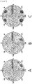
- Figure 2 is graphs measuring luminance in a black state in all directions (phi: 0° to 360°) according to tilt angles as Lb contours
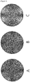
- Figure 3 is graphs measuring visual appreciation in a black state in all directions (phi: 0° to 360°) as Cb contours.
- the black state means a state where a black screen is formed when a liquid crystal panel has been driven, and the black state has been realized in a state where a liquid crystal panel is not driven in the optical characteristic evaluation.
- Lb max means a black luminance value at an azimuth angle indicating the maximum black luminance among the values measuring the black luminance at a tilt angle of 60° in all directions. Since the contrast ratio is defined as the luminance in the white state with respect to the luminance in the black state, it means that the lower the Lb max value, the better the contrast ratio in the viewing angle.
Landscapes
- Physics & Mathematics (AREA)
- Nonlinear Science (AREA)
- General Physics & Mathematics (AREA)
- Optics & Photonics (AREA)
- Mathematical Physics (AREA)
- Chemical & Material Sciences (AREA)
- Crystallography & Structural Chemistry (AREA)
- Geometry (AREA)
- Spectroscopy & Molecular Physics (AREA)
- Polarising Elements (AREA)
- Liquid Crystal (AREA)
Abstract
Description
- This application relates to a liquid crystal display device.
- This application claims the benefit of priority based on Korean Patent Application No.
10-2018-0063443 filed on June 1, 2018 - An IPS mode LCD (in-plane switching liquid crystal display) refers to an LCD in which the initial liquid crystal orientation is horizontal to a glass substrate and liquid crystals are oriented to have a certain angle with respect to an electrode, and an electric field direction is formed parallel to the glass substrate. Conventional viewing angle compensation films used in IPS mode LCDs have been generally used to make colors of polarizing plates bluish, but it is also an important issue in the future to improve contrast ratios in viewing angles as well as colors using the viewing angle compensation films (Prior Art Document: Korean Laid-Open Patent Publication No.
10-2010-0076892 - The present application provides an in-plane switching mode liquid crystal display device having excellent contrast ratios as well as colors in viewing angles.
- The present application relates to a liquid crystal display device.
Figure 1 exemplarily shows a liquid crystal display device of the present application. As shown inFigure 1 , the liquid crystal display device of the present application may comprise an upper polarizer (10), an in-plane switching mode liquid crystal panel (20), and a lower polarizer (30) sequentially. The liquid crystal display device of the present application may comprise a positive biaxial retardation film (40) and a negative C plate (50) as retardation films between the upper polarizer (10) and the in-plane switching mode liquid crystal panel (20). In the present application, it is possible to provide an in-plane switching mode liquid crystal display device having excellent contrast ratios as well as colors in viewing angles by controlling wavelength dispersibility of the positive biaxial retardation film with flat dispersibility. Hereinafter, the liquid crystal display device of the present application will be described in detail. - In this specification, the term upper may mean, when a display device implements images, a direction from the display device to an observer observing the images, and the term lower may mean the opposite direction. The upper polarizer may also be referred to, in another term, as a viewer-side polarizer. Furthermore, in this specification, the term lower polarizer may also be referred to as a back-side polarizer or a light-source-side polarizer.
- In this specification, the terms, polarizer and polarizing plate, refer to objects that are distinguishable from each other. The term polarizer means a film, sheet or element itself having a polarizing function, and the term polarizing plate means an object comprising the polarizer and another element laminated on one or both sides of the polarizer. Here, as another element, a protective film of a polarizer, a pressure-sensitive adhesive layer, an adhesive layer, a retardation film or a low reflection layer, and the like may be exemplified.
- As the protective film which can be contained in the polarizing plate, a film of a known material can be used. As such a material, for example, a thermoplastic resin having excellent transparency, mechanical strength, thermal stability, moisture barrier property or isotropy, and the like can be used. An example of such a resin can be exemplified by a cellulose resin such as triacetyl cellulose (TAC), a polyester resin, a polyethersulfone resin, a polysulfone resin, a polycarbonate resin, a polyamide resin, a polyimide resin, a polyolefin resin, a (meth)acrylic resin, a cyclic polyolefin resin such as a norbornene resin, a polyarylate resin, a polystyrene resin, a polyvinyl alcohol resin or a mixture thereof, and the like.
- As the protective film, an optically anisotropic film with a retardation value or an optically isotropic film without any retardation value can be used. In one example, as the protective film, an isotropic film can be used.
- The protective film may be present on one side or both sides of the polarizer, and when present on both sides, the respective protective films may be the same or different.
- In one example, a positive biaxial retardation film and a negative biaxial retardation film may be sequentially formed on one side of the upper polarizer. At this time, a protective film may or may not be present between the upper polarizer and the positive biaxial retardation film. When a protective film is present, the protective film may be a protective film without any retardation value.
- The polarizer is a functional element capable of extracting light that vibrates in one direction from incident light that vibrates in various directions. As the polarizer, for example, a known absorption linear polarizer can be used. As such a polarizer, a PVA (poly(vinyl alcohol)) polarizer can be exemplified. In one example, the polarizer may be a PVA film or sheet that a dichroic dye or iodine is adsorbed and oriented. The PVA can be obtained by, for example, gelling polyvinyl acetate. The polyvinyl acetate can be exemplified by a homopolymer of vinyl acetate; and a copolymer of vinyl acetate and another monomer, and the like. Here, another monomer copolymerized with vinyl acetate can be exemplified by one or two or more of an unsaturated carboxylic acid compound, an olefin compound, a vinyl ether compound, an unsaturated sulfonic acid compound and an acrylamide compound having an ammonium group, and the like. The polyvinyl acetate has generally a gelation degree of about 85 mol% to about 100 mol% or 98 mol% to 100 mol% or so. The polyvinyl alcohol in the linear polarizer may generally have a polymerization degree of about 1,000 to about 10,000 or about 1,500 to about 5,000.
- In this specification, the retardation film may mean an element capable of converting incident polarized light by controlling birefringence as an optically anisotropic layer. In this specification, when x-, y- and z-axes of the retardation film are described, the x-axis means the direction parallel to the in-plane slow axis of the retardation film, the y-axis means the direction parallel to the in-plane fast axis of the retardation film, and the z axis means the thickness direction of the retardation film, unless otherwise specified. The x-axis and the y-axis may be orthogonal to each other in the plane. In this specification, when the retardation film comprises rod-shaped liquid crystal molecules, the slow axis may mean the long axis direction of the rod shape, and when the retardation film comprises disk-shaped liquid crystal molecules, the slow axis may mean the normal direction of the disk shape. In this specification, when an optical axis of the retardation film is described, it means a slow axis, unless otherwise specified. In this specification, when a refractive index of the retardation film is described, it means a refractive index for light having a wavelength of about 550 nm, unless otherwise specified.
- In this specification, when the term such as vertical, horizontal, orthogonal or parallel is used while defining an angle, it means substantially vertical, horizontal, orthogonal, or parallel to the extent that the desired effect is not impaired, which includes, for example, an error that takes a production error or a deviation (variation), and the like, into account. For example, each case of the foregoing may include an error within about ±15 degrees, an error within about ±10 degrees or an error within about ±5 degrees.
- In this specification, the in-plane retardation (Rin) and the thickness direction retardation (Rth) of the retardation film or a liquid crystal layer are calculated by the following equations 1 and 2, respectively. In this specification, Rin (λ) means an in-plane retardation value of a liquid crystal layer or a retardation film for a wavelength of λnm, and Rth (λ) means a thickness direction retardation value of a liquid crystal layer or a retardation film for a wavelength of λnm.


- In Equations 1 to 2, d is the thickness of the retardation film or the liquid crystal layer, and nx, ny and nz are the refractive indexes of the retardation film or the liquid crystal layer in the x-, y- and z-axis directions, respectively. The x-axis means the direction parallel to the in-plane slow axis of the retardation film or the liquid crystal layer, the y-axis means the direction parallel to the in-plane fast axis of the retardation film or the liquid crystal layer, and the z-axis means the thickness direction of the retardation film or the liquid crystal layer. In this specification, when an in-plane retardation value and a thickness direction retardation value of a retardation film or a liquid crystal layer are described, they mean retardation values for light having a wavelength of about 550 nm, unless otherwise specified.
- In this specification, an Nz value of the retardation film can be calculated by the following equation 3.

- In Equation 3, nx, ny and nz are the refractive indexes of the retardation film in the x-axis, y-axis and z-axis directions as defined above, respectively.
- In this specification, the positive biaxial retardation film means a retardation film satisfying the following equation 4, which may be called a so-called +B plate. In one example, the positive biaxial retardation film may satisfy nz>nx or satisfy nx>nz while satisfying the following equation 4. In one example, when nz>nx is satisfied, the Nz value may be a negative number of less than 0. In another example, when nx>nz is satisfied, the Nz value may be more than 0 to less than 1.
- In this specification, the negative C plate may mean a retardation film satisfying the following equation 5. Since the negative C plate is nx=ny, the Nz value is undefined or has an infinite (∞) value.


- In one example, the absorption axis of the upper polarizer and the absorption axis of the lower polarizer may be orthogonal. In one example, the lower polarizer may be disposed closer to a light source side than the upper polarizer. Therefore, the positive biaxial retardation film and the negative C plate disposed between the upper polarizer and the liquid crystal panel can perform compensation for the light that has passed through a liquid crystal panel. As described below, the liquid crystal panel may comprise a liquid crystal layer between the upper substrate and the lower substrate. At this time, a retardation value difference may occur between the upper substrate and the lower substrate depending on the structure of the upper substrate and the lower substrate. If a positive biaxial retardation film and a negative C plate are disposed between the lower polarizer and the liquid crystal panel to compensate for the light before passing through the liquid crystal panel, the compensation point can be changed while passing through the liquid crystal panel due to the retardation value difference, and thus it is difficult to maximize the effect of improving the contrast ratio in the viewing angle even if the positive biaxial retardation film with flat dispersibility is used. In the present invention, the compensation is performed after passing through the liquid crystal panel by disposing the retardation film between the upper polarizer and the liquid crystal panel, so that the compensation path can be set to the target compensation point at the linearly polarized light position, where it is possible to maximize the effect of improving the contrast ratio in the viewing angle by controlling the wavelength dispersibility of the positive biaxial retardation film to the flat dispersibility.
- The positive biaxial retardation film may have flat dispersibility. The flat dispersibility may mean the following retardation value characteristics. The positive biaxial retardation film may have a Rin (450)/Rin (550) value in a range of 0.99 to 1.01. The positive biaxial retardation film may have a Rin (650)/Rin (550) value in a range of 0.99 to 1.01. When the positive biaxial retardation film having flat dispersibility is used, a bluish color can be exhibited at a viewing angle, and a contrast ratio at a viewing angle can also be improved.
- In one example, the positive biaxial retardation film may have an in-plane retardation value of more than 0 nm to 300 nm or less for light having a wavelength of 550 nm. The in-plane retardation value may be, specifically, from more than 0 nm, 50 nm or more, 80 nm or more, 100 nm or more, or 110 nm or more, to 300 nm or less, 250 nm or less, 200 nm or less, 150 nm or less, or 120 nm or less. Within such a retardation value range, it may be advantageous to provide an in-plane switching mode liquid crystal display device having excellent contrast ratios as well as colors in viewing angles.
- In one example, the positive biaxial retardation film may have a thickness direction retardation value of -300 nm to -40 nm. The thickness direction retardation value may be, specifically, from -300 nm or more, -170 nm or more, -130 nm or more, or -120 nm or more, to -40 nm or less, -90 nm or less, or -100 nm or less. Within such a retardation value range, it may be advantageous to provide an in-plane switching mode liquid crystal display device having excellent contrast ratios as well as colors in viewing angles.
- In one example, the Nz value of the positive biaxial retardation film in Equation 3 above may be less than 1. At this time, the case where the Nz value is 0 can be excluded. Accordingly, the Nz value may be less than 0, or more than 0 to less than 1. The Nz value may be, specifically, -1 or more, or -0.5 or more, and may be 0.5 or less, or less than 0. Within such an Nz value range, it may be advantageous to provide an in-plane switching mode liquid crystal display device having excellent contrast ratios as well as colors in viewing angles.
- In one example, the slow axis of the positive biaxial retardation film may be parallel to the absorption axis of the upper polarizer. If the slow axis of the positive biaxial film and the absorption axis of the upper polarizer are not parallel to each other, a light leakage phenomenon may occur due to light projection between the lower polarizer and the upper polarizer on the optical path.
- In one example, the positive biaxial retardation film may be disposed adjacent to the upper polarizer over the negative C plate. Through this arrangement, it may be advantageous to provide an in-plane switching mode liquid crystal display device having excellent colors and contrast ratios in viewing angles.
- In one example, the negative C plate may have a thickness direction retardation value of 40 nm to 130 nm. Specifically, the thickness direction retardation value may be from 40 nm or more, 50 nm or more, 70 nm or more, 90 nm or more, 100 nm or more, or 110 nm or more, to 130 nm or less, or 120 nm or less. Within such a retardation value range, it may be advantageous to provide an in-plane switching mode liquid crystal display device having excellent contrast ratios as well as colors in viewing angles.
- The thickness of the negative C plate may be in a range of 0.5µm to 30µm. The thickness of the entire retardation film including the positive biaxial film and the negative C plate may be in the range of 20µm to 100µm.
- The positive biaxial retardation film may be a polymer stretched film or a liquid crystal polymerized film. The polymer stretched film may comprise a stretched polymer layer obtained by stretching a polymer film, which is capable of imparting optical anisotropy by stretching, in a suitable manner. The liquid crystal polymerized film may comprise a liquid crystal polymer layer or a cured layer of a polymerizable liquid crystal compound.
- Here, as the polymer stretched film, for example, a polymer layer comprising a polyolefin such as polyethylene or polypropylene, a cycloolefin polymer (COP) such as polynorbornene, polyvinyl chloride, polyacrylonitrile, polysulfone, an acrylic resin, polycarbonate, a polyester such as polyethylene terephthalate, polyacrylate, polyvinyl alcohol, a cellulose ester polymer such as TAC (triacetyl cellulose), a copolymer of two or more monomers among the monomers forming the polymer, and the like can be used.
- In one example, the positive biaxial retardation film may comprise an acrylate-based resin. As described below, the retardation film may be produced by a method of film-forming a resin composition and stretching it. Therefore, the resin composition for producing a positive biaxial retardation film may comprise an acrylate resin.
- In one example, the acrylate-based resin may have a glass transition temperature (Tg) of 120°C or more. The glass transition temperature of the acrylate-based resin may be, specifically, 120°C or more, or 125°C or more, and may be 150°C or less, or 145°C or less. In this specification, the glass transition temperature has been measured using DSC (differential scanning calorimeter) equipment from METTLER Co., and the measuring method includes steps of placing 3mg to 20mg of a resin to be measured in an aluminum crucible, melting the resin from 30°C to 250°C at a heating rate of 10°C per minute, and cooling the resin again to 30°C and then melting it again at a heating rate of 10°C per minute up to 200°C. At this time, through the DSC equipment from METTLER Co., the midpoint of the temperature range where the specific heat behavior of the resin changes during the second melting process is measured, and this value is measured as the glass transition temperature value.
- In one example, the acrylate-based resin may comprise a (meth)acrylate-based resin having a weight average molecular weight of 100,000 g/mol to 5,000,000 g/mol. The weight average molecular weight can be measured by a gel permeation chromatography (GPC) analysis.
- In this specification, the (meth)acrylate has a meaning to include both acrylate and methacrylate. The (meth)acrylate-based resin may be, for example, a copolymer of a (meth)acrylic acid ester-based monomer and a crosslinkable functional group-containing monomer.
- The (meth)acrylic acid ester-based monomer is not particularly limited, but may include, for example, alkyl (meth)acrylates, and more specifically, may include, as a monomer having an alkyl group with 1 to 12 carbon atoms, one or two or more of pentyl (meth)acrylate, n-butyl (meth)acrylate, ethyl (meth)acrylate, methyl (meth)acrylate, hexyl (meth)acrylate, n-octyl (meth)acrylate, isooctyl (meth)acrylate, 2-ethylhexyl (meth)acrylate, dodecyl (meth)acrylate and decyl (meth)acrylate.
- The crosslinkable functional group-containing monomer is not particularly limited, but may include, for example, one or two or more of a hydroxyl group-containing monomer, a carboxyl group-containing monomer and a nitrogen-containing monomer.
- An example of the hydroxyl group-containing compound may include 2-hydroxyethyl (meth)acrylate, 2-hydroxypropyl (meth)acrylate, 4-hydroxybutyl (meth)acrylate, 6-hydroxyhexyl (meth)acrylate, 8-hydroxyoctyl (meth)acrylate, 2-hydroxyethylene glycol (meth)acrylate or 2-hydroxypropylene glycol (meth)acrylate, and the like.
- An example of the carboxyl group-containing compound may include (meth)acrylic acid, 2-(meth)acryloyloxyacetic acid, 3-(meth)acryloyloxypropionic acid, 4-(meth)acryloyloxybutyric acid, an acrylic acid dimer, itaconic acid, maleic acid or maleic anhydride, and the like.
- An example of the nitrogen-containing monomer may include (meth)acrylonitrile, N-vinylpyrrolidone or N-vinylcaprolactam, and the like.
- From the viewpoint of improvement of other function properties such as compatibility, the (meth)acrylate-based resin may be further copolymerized with at least one of vinyl acetate, styrene and acrylonitrile.
- In one example, the acrylate-based resin may have one or more monomers selected from the group consisting of an N-substituted maleimide structure, a lactone ring structure and a glutarimide structure in an acrylate molecular chain. In the acrylate-based resin, the N-substituted maleimide structure, the lactone ring structure and the glutarimide structure can be confirmed by nuclear magnetic resonance (NMR) measurement. In one example, the N-substituted maleimide structure may be N-phenylmaleimide (PMI).
- The presence of the monomer in the acrylate molecular chain means that 1 to 40 parts by weight, preferably 5 to 30 parts by weight, more preferably 5 to 20 parts by weight of the monomer is contained based on 100 parts by weight of the acrylic resin, and when the monomer is contained in the acrylate molecular chain, a copolymer can be formed.
- In the copolymer, a product obtained by polymerizing two or more different units is referred to as a copolymer, where two or more units may be arranged irregularly or regularly. The copolymer may include a random copolymer having a form that monomers are randomly mixed with each other, a block copolymer that the blocks arranged in a predetermined section are repeated or an alternating copolymer having a form that monomers are alternately repeated and polymerized, and the acrylate-based resin according to one embodiment of the present application may be a random copolymer, a block copolymer or an alternating copolymer.
- In one example, the acrylate-based resin may be a lactone-methyl methacrylate (Lactone-MMA), maleimide-methyl methacrylate (Maleimide-MMA) or glutamide-methyl methacrylate (Glutaimide-MMA).
- The positive biaxial retardation film and/or the resin composition for producing the film may further comprise a retardation regulator in addition to the acrylate resin. The retardation regulator may include a styrene monomer. The retardation regulator may be, for example, styrene-acrylonitrile (SAN).
- When styrene is used alone as a retardation regulator, the usability with the acrylate-based resin is not exhibited, but styrene-acrylonitrile (SAN) used together with acrylonitrile is used, whereby the usability with the acrylate-based resin may be sufficient.
- In one example, the retardation regulator may be contained in an amount from 15 parts by weight or more, 20 parts by weight or more, or 30 parts by weight or more, to 80 parts by weight or less, or 75 parts by weight or less, relative to 100 parts by weight of the acrylate-based resin. When the retardation regulator is contained in the above content range, it may be advantageous in terms of realizing the flat wavelength dispersion of the retardation film and securing the heat resistance of the retardation film by setting the glass transition temperature of the resin composition for producing the retardation film within the appropriate range.
- In one example, the positive biaxial retardation film and/or the resin composition for producing the film may further comprise a triazine-based birefringence regulator in addition to the acrylate-based resin and the retardation regulator. When the triazine-based birefringence regulator is used, it may be more advantageous to realize the flat wavelength dispersibility by utilizing the refractive index difference with the acrylate-based resin.
- In one example, the triazine-based birefringence regulator may be contained in an amount from 5 parts by weight or more, 5.5 parts by weight or more, or 6.5 parts by weight or more, to 15 parts by weight or less, 14 parts by weight or less, or 13 parts by weight or less, relative to 100 parts by weight of the acrylate-based resin. When the triazine-based birefringence regulator is contained in the above content range, it may be more suitable for realizing flat wavelength dispersibility in general normal dispersion, where it has an excellent optical characteristic.
- In one embodiment of the present application, the triazine-based birefringence regulator may be a 2-hydroxyphenyl-s-triazine derivative, and may include, specifically, Tinuvin 1600, Tinuvin 460, Tinuvin477, Tinuvin479 and Tinuvin1577 from BASF and/or LA-F70 and LA46 from ADEKA, and the like, but is not limited thereto.
- In one example, the triazine-based birefringence regulator may be a compound of the following formula 1.

- In Formula 1 above, L1 to L3 are the same or different from each other, and are each independently a direct bond, a substituted or unsubstituted arylene group or a substituted or unsubstituted heteroarylene group; Z1 to Z3 are the same or different from each other, and are each independently hydrogen, a hydroxyl group, a substituted or unsubstituted alkoxy group, a substituted or unsubstituted alkyl group, a substituted or unsubstituted aryl group or a substituted or unsubstituted heteroaryl group; a, b and c are the same or different from each other, and are each independently an integer of 1 to 3; p, q and r are the same or different from each other, and are each independently an integer of 1 to 5; and when a, b, c, p, q and r are an integer of 2 or more, two or more substituents in parentheses are the same or different from each other.
- Illustrative examples of such substituents are set forth below, but are not limited thereto.
- In this specification, the term "substituted or unsubstituted" means that it is substituted or unsubstituted with one or more substituents selected from the group consisting of an alkoxy group; an alkyl group; an aryl group; and a heterocyclic group, or substituted or unsubstituted with a substituent formed by two or more substituents of the above-exemplified substituents connected to each other. For example, the "substituent formed by two or more substituents connected to each other" may be a biphenyl group. That is, the biphenyl group may be an aryl group, and may be interpreted as a substituent in which two phenyl groups are connected to each other.
- In this specification, the alkyl group may be linear or branched, and the number of carbon atoms is not particularly limited, but is preferably 1 to 40. According to one embodiment, the alkyl group has 1 to 20 carbon atoms. According to another embodiment, the alkyl group has 1 to 10 carbon atoms. According to another embodiment, the alkyl group has 1 to 6 carbon atoms. A specific example of the alkyl group includes a methyl group, an ethyl group, a propyl group, an n-propyl group, an isopropyl group, a butyl group, an n-butyl group, an isobutyl group, a tert-butyl group, a sec-butyl group, an 1-methyl-butyl group, an 1-ethyl-butyl group, a pentyl group, an n-pentyl group, an isopentyl group, a neopentyl group, a tert-pentyl group, a hexyl group, an n-hexyl group, an 1-methylpentyl group, a 2-methylpentyl group, a 4-methyl-2-pentyl group, a 3,3-dimethylbutyl group, 2-ethylbutyl group, a heptyl group, an n-heptyl group, an 1-methylhexyl group, a cyclopentylmethyl group, a cyclohexylmethyl group, an octyl group, an n-octyl group, a tert-octyl group, an 1-methylheptyl group, a 2-ethylhexyl group, a 2-propylpentyl group, an n-nonyl group, a 2,2-dimethylheptyl group, an 1-ethyl-propyl group, an 1,1-dimethyl-propyl group, an isohexyl group, a 4-methylhexyl group, a 5-methylhexyl group, and the like, but is not limited thereto.
- In this specification, the alkoxy group may be linear, branched or cyclic. The number of carbon atoms of the alkoxy group is not particularly limited, but is preferably 1 to 40. Specifically, it may be methoxy, ethoxy, n-propoxy, isopropoxy, n-butoxy, isobutoxy, tert-butoxy, sec-butoxy, n-pentyloxy, neopentyloxy, isopentyloxy, n-hexyloxy, 3,3-dimethylbutyloxy, 2-ethylbutyloxy, n-octyloxy, n-nonyloxy, n-decyloxy, benzyloxy, p-methylbenzyloxy, and the like, but is not limited thereto.
- The alkyl group, the alkoxy group and other substituents comprising alkyl group moieties as described herein include both linear and branched forms.
- In this specification, the aryl group is not particularly limited, but has preferably 6 to 60 carbon atoms, which may be a monocyclic aryl group or a polycyclic aryl group. According to one embodiment, the aryl group has 6 to 30 carbon atoms. According to one embodiment, the aryl group has 6 to 20 carbon atoms. The aryl group may be a phenyl group, a biphenyl group, a terphenyl group or the like as the monocyclic aryl group, but is not limited thereto. The polycyclic aryl group may be a naphthyl group, an anthracenyl group, a phenanthryl group, a pyrenyl group, a perylenyl group, a triphenyl group, a chrysenyl group, a fluorenyl group or the like, but is not limited thereto.
- In this specification, the heterocyclic group is a heterocyclic group containing, as heteroatoms, one or more of N, O, P, S, Si and Se, wherein the number of carbon atoms is not particularly limited, but is preferably 1 to 60. According to one embodiment, the heterocyclic group has 1 to 30 carbon atoms. An example of the heterocyclic group includes a pyridyl group, a pyrrol group, a pyrimidyl group, a pyridazinyl group, a furanyl group, a thiophenyl group, an imidazole group, a pyrazole group, an oxazole group, an isoxazole group, a thiazole group, a isothiazole group, a triazole group, an oxadiazole group, a thiadiazole group, a dithiazole group, a tetrazole group, a pyranyl group, a thiopyranyl group, a pyrazinyl group, an oxazinyl group, a thiazinyl group, a dioxinyl group, a triazinyl group, a tetrazinyl group, a quinolinyl group, an isoquinolinyl group, a quinolyl group, a quinazolinyl group, a quinoxalinyl group, a naphthyridinyl group, a acridinyl group, a xanthenyl group, a phenanthridinyl group, a diazanaphthalenyl group, a triazaindenyl group, an indole group, an indolinyl group, an indolizinyl group, a phthalazinyl group, a pyridopyrimidinyl group, a pyridopyrazinyl group, a pyrazinopyrazinyl group, a benzothiazole group, a benzoxazole group, a benzimidazole group, a benzothiophene group, a benzofuranyl group, a dibenzothiophenyl group, a dibenzofuranyl group, a carbazole group, a benzocarbazole group, a dibenzocarbazole group, an indolocarbazole group, an indenocarbazole group, a phenazinyl group, an imidazopyridine group, a phenoxazinyl group, a phenanthridine group, a phenanthroline group, a phenothiazine group, an imidazopyridine group, an imidazophenanthridine group, a benzoimidazoquinazoline group or a benzoimidazophenanthridin group, and the like, but is not limited thereto.
- In this specification, the description of the heterocyclic group as described above can be applied to the heteroaryl group, except that it is aromatic. In this specification, the description of the aryl group as described above can be applied to the arylene, except that it is a divalent group.
- In one example, L1 to L3 may be a direct bond; or a substituted or unsubstituted arylene group having 6 to 60 carbon atoms, specifically, an arylene group having 6 to 40 carbon atoms, more specifically a perylene group. In one example, Z1 to Z3 may be hydrogen; a hydroxyl group; a substituted or unsubstituted aryl group having 6 to 60 carbon atoms, specifically an aryl group having 6 to 40 carbon atoms, more specifically a phenyl group; or an alkoxy group substituted or unsubstituted with an alkyl group having 1 to 40 carbon atoms, specifically an alkoxy group substituted or unsubstituted with a branched alkyl group having 1 to 10 carbon atoms.
- In one specific example, the triazine-based birefringence regulator may be a compound, wherein in Formula 1 above, L1 to L3 are each a direct bond and at least one of Z1 to Z3 is a substituted or unsubstituted aryl group. As the triazine-based birefringence regulator having such a structure, Tinuvin 1600 from BASF can be exemplified. In the case where at least one of Z1 to Z3 is a phenyl group, the difference in birefringence is larger than that in other cases, and thus, the compound in which at least one of Z1 to Z3 is a phenyl group may be advantageous in terms of the effect of improving the wavelength dispersibility as compared with other compounds.
- The contents and components of the acrylate resin, the styrene monomer-containing retardation regulator and the triazine-based birefringence regulator in the retardation film and/or the resin composition may each be confirmed by nuclear magnetic resonance (NMR) and gas chromatography (GC) analyses.
- The resin composition may have a glass transition temperature of 115°C or higher. The glass transition temperature of the resin composition may be specifically 118°C or higher, and may be 150°C or lower, or 130°C or lower. The glass transition temperature of the resin composition can be controlled within the above range by the acrylate-based resin having a glass transition temperature of 120°C or higher, and accordingly, the retardation film has excellent heat resistance characteristics.
- As described above, the retardation film can be produced by a method of preparing the resin composition, and then film-forming it and stretching it.
- The resin composition is prepared by pre-blending the film raw materials with any suitable mixer such as, for example, an omni mixer, and then extruding and kneading the resulting mixture. In this case, the mixer used for the extruding and kneading is not particularly limited, and for example, an extruder such as a single-screw extruder and a twin-screw extruder, or any suitable mixer such as a pressurized kneader may be used.
- The film forming method may include, for example, any suitable film forming method such as a solution casting method (solution softening method), a melt extrusion method, a calendering method and a compression molding method. Among these film forming methods, a solution casting method (solution softening method) and a melt extrusion method are preferable.
- The solvent used in the solution casting method (solution softening method) may include, for example, aromatic hydrocarbons such as benzene, toluene and xylene; aliphatic hydrocarbons such as cyclohexane and decaline; esters such as ethyl acetate and butyl acetate; ketones such as acetone, methyl ethyl ketone and methyl isobutyl ketone; alcohols such as methanol, ethanol, isopropanol, butanol, isobutanol, methyl cellosolve, ethyl cellosolve and butyl cellosolve; ethers such as tetrahydrofuran and dioxane; halogenated hydrocarbons such as dichloromethane, chloroform and carbon tetrachloride; dimethylformamide; dimethyl sulfoxide, and the like. These solvents may be used alone or in combination of two or more.
- The apparatus for carrying out the solution casting method (solution softening method) may include, for example, a drum casting machine, a band casting machine, a spin coater, and the like. On the other hand, the melt extrusion method may include, for example, a T-die method, an inflation method, and the like. The forming temperature may be 150°C to 350°C, or 200°C to 300°C.
- When a film is formed by the T-die method, a roll shape film can be obtained by mounting a T-die on the tip of a known single-screw extruder or a twin-screw extruder and winding a film extruded in a film shape.
- After the film is formed through the above process, the film is stretched. The stretching process may perform longitudinal direction (MD) stretching, transverse direction (TD) stretching, or both. Furthermore, in the case of performing both the longitudinal direction stretching and the transverse direction stretching, any one direction may be first stretched and then the other direction may be stretched, or both directions may be stretched at the same time. The stretching may be performed in one step or in multiple steps. In the case of longitudinal stretching, the stretching by the speed difference between rolls can be performed, and in the case of transverse stretching, a tenter can be used. As the rail start angle of the tenter is usually set within 10 degrees, a bowing phenomenon occurring upon the transverse direction stretching is suppressed and the angle of the optical axis is regularly controlled. Even when the transverse direction stretching is performed in multiple steps, the effect of suppressing the bowing can be obtained.
- The stretching temperature is preferably in a range near the glass transition temperature of the resin composition which is the raw material of the film, and when the glass transition temperature of the composition is Tg, it is in the range of, preferably, (Tg-30°C) to (Tg+100°C), more preferably, (Tg-20°C) to (Tg+80°C), and still more preferably, (Tg-5°C) to (Tg+20°C). If the stretching temperature is less than (Tg-30°C), there is a risk that a sufficient draw ratio may not be obtained. On the contrary, if the stretching temperature is higher than (Tg+100°C), the flow of the resin composition occurs, whereby there is a risk that stable stretching may not be performed.
- In one embodiment of the present application, the draw ratio in the step of stretching the film may also be 1.05 to 10 times based on the length in the stretching direction.
- Furthermore, it may be stretched so that the total draw ratio is 1.1 times or more, 1.2 times or more, or 1.5 times or more, and is 25 times or less, 10 times or less, or 7 times or less, based on the total stretching area. When the draw ratio is less than 1.1 times, the effect of stretching may not be sufficiently achieved, and when the draw ratio is more than 25 times, the film layer may be cracked.
- In order to stabilize the optical isotropy and mechanical properties of the retardation film, heat treatment (annealing) or the like may be performed after the stretching treatment. The heat treatment conditions are not particularly limited and any suitable conditions known to those skilled in the art can be adopted.
- The liquid crystal polymerized film may comprise a base layer and a liquid crystal layer on one side of the base layer. The contents of the base layer in the antireflection film may be applied to the base layer of the liquid crystal polymerized film in the same manner. Therefore, for the base layer of the liquid crystal polymerized film, a light-transmissive base material can also be used. The liquid crystal layer may comprise a polymerizable liquid crystal compound in a polymerized state. In this specification, the term "polymerizable liquid crystal compound" may mean a compound containing a moiety capable of exhibiting liquid crystallinity, for example, a mesogen skeleton or the like, and also containing one or more polymerizable functional groups. Such polymerizable liquid crystal compounds are variously known under the so-called RM (reactive mesogen). The polymerizable liquid crystal compound may be contained in the polymerized form, that is, the above-described polymerized unit in the cured layer, which may mean a state where the liquid crystal compound is polymerized to form a skeleton such as a main chain or a side chain of the liquid crystal polymer in the cured layer.
- The polymerizable liquid crystal compound may be a monofunctional or multifunctional polymerizable liquid crystal compound. Here, the monofunctional polymerizable liquid crystal compound is a compound having one polymerizable functional group, and the multifunctional polymerizable liquid crystal compound may mean a compound containing two or more polymerizable functional groups. In one example, the multifunctional polymerizable liquid crystal compound may comprise 2 to 10, 2 to 8, 2 to 6, 2 to 5, 2 to 4, 2 to 3, two or three polymerizable functional groups.
- It is known that a polymerizable liquid crystal composition prepared by compounding such a polymerizable liquid crystal compound, for example, with other components such as an initiator, a stabilizer and/or a non-polymerizable liquid crystal compound is cured in a state oriented on an alignment film to form the cured layer with the developed birefringence. The retardation film having flat dispersion characteristics can be produced by comprising a polymerizable liquid crystal compound having flat dispersion characteristics.
- In one example, the negative C plate may comprise a material having a negative retardation value in the thickness direction and high birefringence. The material having a negative retardation value in the thickness direction and high birefringence can be exemplified by a compound containing an aromatic ring or a cycloolefin series in a polymer main chain.
- A specific example of the negative C plate can be exemplified by a cellulose ester-based polymer film such as TAC (triacetyl cellulose), a polyarylate film, a polynorbornene film, a polycarbonate film, a polysulfone film, a polyimide film or a copolymer film of two or more monomers among the monomers forming the polymer, and the like.
- The polyarylate may comprise a compound represented by the following formula 2.

- In Formula 2 above, n is an integer of 1 or more.
- In one example, the retardation films and the polarizers may be attached to each other via a pressure-sensitive adhesive or an adhesive, or may be laminated to each other by direct coating. An optically transparent pressure-sensitive adhesive or adhesive may be used as the pressure-sensitive adhesive or the adhesive.
- In one example, the in-plane switching mode liquid crystal panel may comprise a liquid crystal layer. Also, the in-plane switching mode liquid crystal panel may further comprise an upper substrate and a lower substrate on upper and lower parts of the liquid crystal layer, respectively. The upper substrate and the lower substrate may each be a glass substrate or a plastic substrate. In one example, any one of the upper substrate and the lower substrate may be a color filter substrate, and the other may be a TFT (thin film transistor) substrate. Since the color filter and the TFT may each have an inherent phase difference, a difference in retardation value may occur between the upper substrate and the lower substrate. In one example, the thickness direction retardation (Rth) value of the color filter substrate may be less than 10 nm. In the present invention, the compensation can be performed after passing through the liquid crystal panel by disposing the retardation film between the upper polarizer and the liquid crystal panel, so that the compensation path can be set to the target compensation point at the linearly polarized light position, where it is possible to maximize the effect of improving the contrast ratio in the viewing angle by controlling the positive biaxial retardation film so as to have the flat dispersibility.
- The liquid crystal layer may comprise liquid crystals having positive or negative dielectric constant anisotropy. The dielectric constant anisotropy of the liquid crystal layer can be appropriately selected in accordance with the mode of a desired liquid crystal panel. The liquid crystal layer may comprise the liquid crystals in a horizontally oriented state. In one example, the in-plane retardation (Rin) value of the liquid crystal layer may be in a range of 310 nm to 350 nm. The in-plane retardation (Rin) value of the liquid crystal layer may be 310 nm or more, 315 nm or more, 320 nm or more, 325 nm or more, or 330 nm or more, and may be 350 nm or less, 345 nm or less, or 340 nm or less. The thickness direction retardation (Rth) value of the liquid crystal layer may be 0 nm to -40 nm. The liquid crystal layer may have a pretilt angle of, for example, less than 0.2°.
- Herein, the pretilt may have an angle and a direction. The pretilt angle may be referred to as a polar angle, and the pretilt direction may be referred to as an azimuthal angle.
- The pretilt angle may mean an angle formed by a liquid crystal director with respect to the horizontal surface of the substrate. The pretilt direction may mean a direction that the liquid crystal director is projected on the horizontal surface of the substrate. The pretilt direction may mean the orientation direction of the liquid crystals of the initial state in the liquid crystal layer which is described below.
- In this specification, the term "liquid crystal director" may mean a long axis when the liquid crystal has a rod shape and may mean an axis of a normal direction of a disk plane when the liquid crystal has a discotic shape.
- The combination of the positive biaxial retardation film and the negative C plate may be suitable for improving the colors and the contrast ratios of the in-plane switching mode liquid crystal panel comprising the liquid crystal layer having the retardation value at the viewing angles.
- The upper substrate and the lower substrate of the in-plane switching mode liquid crystal panel may further comprise alignment films on the liquid crystal layer side, respectively. The orientation direction of the liquid crystals can be determined by the alignment film. The alignment film may be a horizontal alignment film. As the alignment film, a rubbing alignment film or a photo alignment film can be used.
- In one example, the liquid crystal display device may further comprise a light source adjacent to the lower polarizer as compared to the upper polarizer. In one example, the light source may be included in the liquid crystal display device in a state of being included in a backlight unit. The backlight unit may further comprise a light guide plate for guiding light emitted from the light source, a reflection sheet located on the lower part of the light guide plate, and a diffusion sheet located on the upper part of the light guide plate. The light source generates light, which may be disposed on the side of the light guide plate (edge type). As the light source, various light sources, such as a linear light source lamp, a surface light source lamp, a CCFL or an LED, can be used. A light source cover may be disposed outside the light source. The light guide plate can guide the light generated from the light source to the diffusion sheet. The light guide plate may be omitted when a directly-under type light source is employed, and in this case, a diffusion plate may be further included. The reflection sheet may play a role in reflecting the light generated from the light source and supplying the light toward the diffusion sheet. The diffusion sheet can diffuse and scatter light incident through the light guide plate to supply it to the liquid crystal panel.
- In one example, the orientation direction of the liquid crystals in the in-plane switching mode liquid crystal panel (liquid crystal layer) may be parallel to or orthogonal to the absorption axis of the lower polarizer. The orientation direction may mean the orientation direction in an initial state, specifically, a state where no electric field is applied. It can be defined as an O mode liquid crystal panel when the angle is parallel, and it can be defined as an E mode liquid crystal panel when it is orthogonal. In one example, the O mode liquid crystal panel may be preferable from the viewpoint of maximizing the effect of improving the viewing angle contrast ratio.
- The present application can provide an in-plane switching mode liquid crystal display device having excellent contrast ratios as well as colors in viewing angles.
-
-
Figure 1 exemplarily shows a liquid crystal display device of the present application. -
Figure 2 is Lb contour measurement results. -
Figure 3 is Cb contour measurement results. - Hereinafter, the present application will be described in detail by way of examples according to the present application and comparative examples not complying with the present application, but the scope of the present application is not limited by the following examples.
- Design conditions of in-plane switching mode liquid crystal display devices are as follows.
- 1) Liquid crystal panel: an O mode in-plane switching mode liquid crystal panel, having a cell gap (thickness of liquid crystal layer) of 3.4µm, a pretilt angle of 0.1°, dielectric constant anisotropy Δε>0 of liquid crystals, birefringence Δn=0.1 of liquid crystals at a wavelength of 550 nm, Rin (550) of liquid crystal layer of 330 nm, and Rth (550) of liquid crystal layer of 0 nm
- 2) Upper polarizing plate: a polarizing plate in which a positive biaxial retardation film (acrylic film) and a negative C plate (TAC-based film) are sequentially formed on one side of a polarizer
- 3) Lower polarizing plate: a polarizing plate in which an NRT (no retardation TAC) film with a thickness of 60µm is attached to one side of a polarizer
- The polarizers of the upper polarizing plate and the lower polarizing plate are PVA (polyvinyl alcohol) polarizers having a degree of polarization of 99.99% or more and single body transmittance of 42.0% for light having a wavelength of 380 nm to 780 nm (measurement equipment: EZ Contrast equipment from Eldim). An in-plane switching mode liquid crystal display device was manufactured by laminating the negative C plate of the upper polarizing plate to be in contact with the liquid crystal panel, and the NRT film of the lower polarizing plate to be in contact with the liquid crystal panel. As the positive biaxial retardation film, a normal wavelength dispersion retardation film was used in Comparative Example 1, a flat wavelength dispersion retardation film was used in Example 1, and a reverse wavelength dispersion retardation film was used in Comparative Example 2. The retardation values of the positive biaxial retardation film and the retardation values of the negative C plate were described in Table 1 below. The retardation value was measured using Axoscan equipment from Axometrics.
- Using an EZ contrast (Eldim) instrument, the optical characteristics were measured for the in-plane switching mode liquid crystal display device.
Figure 2 is graphs measuring luminance in a black state in all directions (phi: 0° to 360°) according to tilt angles as Lb contours, andFigure 3 is graphs measuring visual appreciation in a black state in all directions (phi: 0° to 360°) as Cb contours. Generally, the black state means a state where a black screen is formed when a liquid crystal panel has been driven, and the black state has been realized in a state where a liquid crystal panel is not driven in the optical characteristic evaluation. In Table 1, Lb max means a black luminance value at an azimuth angle indicating the maximum black luminance among the values measuring the black luminance at a tilt angle of 60° in all directions. Since the contrast ratio is defined as the luminance in the white state with respect to the luminance in the black state, it means that the lower the Lb max value, the better the contrast ratio in the viewing angle.Table 1] Comparative Example 1 Example 1 Comparative Example 2 +B plate Rin(450)/Rin (550) 1.07 1 0.9 Rin(650)/Rin (550) 0.97 0.99 1.02 Rin(550) (nm) 118 118 118 Rth(550) (nm) -118 -118 -118 -C plate Rin(550) (nm) 0 0 0 Rth(550) (nm) 115 115 115 Optical characteristic Lb front 0.6 0.6 0.6 Lb max (60°, max) 0.81 0.91 0.94 Cb Purple+Red Blue Blue+Green - 10: upper polarizer, 20: in-plane switching mode liquid crystal panel, 30: lower polarizer, 40: positive biaxial retardation film 50: negative C plate
Claims (13)
- A liquid crystal display device comprising an upper polarizer, an in-plane switching mode liquid crystal panel including a liquid crystal layer having a Rin (550) value in a range of 310 nm to 350 nm, and a lower polarizer sequentially,
wherein the absorption axis of the upper polarizer and the absorption axis of the lower polarizer are orthogonal;
the lower polarizer is disposed adjacent to a light source as compared to the upper polarizer; and
comprising, as retardation films, a positive biaxial retardation film, wherein a Rin (450)/Rin (550) value is in a range of 0.99 to 1.01, and a negative C plate between the upper polarizer and the in-plane switching mode liquid crystal panel (Rin (λ) is an in-plane retardation value of the liquid crystal layer or the retardation film for a wavelength of λ nm). - The liquid crystal display device according to claim 1, wherein the positive biaxial retardation film has an in-plane retardation value of more than 0 nm to 300 nm for light with a wavelength of 550 nm.
- The liquid crystal display device according to claim 1, wherein the positive biaxial retardation film has a thickness direction retardation value of -300 nm to -40 nm as calculated by the following equation 2:

wherein, nx, ny and nz are the refractive indexes of the retardation film in the x-, y-and z-axis directions, respectively, and d is the thickness of the retardation film, where the x-axis direction means the slow axis direction of the retardation film in the plane direction, the y-axis direction means the fast axis direction of the retardation film in the plane direction and the z-axis direction means the thickness direction of the retardation film. - The liquid crystal display device according to claim 1, wherein the positive biaxial retardation film has a Rin (650)/Rin (550) value in a range of 0.99 to 1.01.
- The liquid crystal display device according to claim 1, wherein the positive biaxial retardation film has an Nz value of -1 or more to less than 1 in the following equation 3:

- The liquid crystal display device according to claim 1, wherein a slow axis of the positive biaxial retardation film is parallel to the absorption axis of the upper polarizer.
- The liquid crystal display device according to claim 1, wherein the positive biaxial retardation film is disposed adjacent to the upper polarizer as compared to the negative C plate.
- The liquid crystal display device according to claim 1, wherein the negative C plate has a thickness direction retardation value of 40 nm to 130 nm as calculated by the following equation 2:

- The liquid crystal display device according to claim 1, wherein the in-plane switching mode liquid crystal panel further comprises an upper substrate and a lower substrate on upper and lower parts of the liquid crystal layer, respectively.
- The liquid crystal display device according to claim 9, wherein any one of the upper substrate and the lower substrate is a color filter substrate and the other is a TFT (thin film transistor) substrate.
- The liquid crystal display device according to claim 1, wherein the liquid crystal layer has a thickness direction retardation value of 0 nm to -40 nm as calculated by the following equation 2:

- The liquid crystal display device according to claim 1, further comprising a light source adjacent to the lower polarizer as compared to the upper polarizer.
- The liquid crystal display device according to claim 1, wherein the orientation direction of the liquid crystal layer in the in-plane switching mode liquid crystal panel is parallel to the absorption axis of the lower polarizer.
Applications Claiming Priority (2)
| Application Number | Priority Date | Filing Date | Title |
|---|---|---|---|
| KR20180063443 | 2018-06-01 | ||
| PCT/KR2019/006638 WO2019231301A1 (en) | 2018-06-01 | 2019-06-03 | Liquid crystal display device |
Publications (2)
| Publication Number | Publication Date |
|---|---|
| EP3805852A1 true EP3805852A1 (en) | 2021-04-14 |
| EP3805852A4 EP3805852A4 (en) | 2021-07-21 |
Family
ID=68698342
Family Applications (1)
| Application Number | Title | Priority Date | Filing Date |
|---|---|---|---|
| EP19811673.3A Pending EP3805852A4 (en) | 2018-06-01 | 2019-06-03 | LIQUID CRYSTAL DISPLAY DEVICE |
Country Status (7)
| Country | Link |
|---|---|
| US (1) | US11467449B2 (en) |
| EP (1) | EP3805852A4 (en) |
| JP (1) | JP7184442B2 (en) |
| KR (1) | KR102167213B1 (en) |
| CN (1) | CN111886538B (en) |
| TW (1) | TWI708079B (en) |
| WO (1) | WO2019231301A1 (en) |
Families Citing this family (2)
| Publication number | Priority date | Publication date | Assignee | Title |
|---|---|---|---|---|
| KR102564216B1 (en) * | 2020-01-03 | 2023-08-04 | 삼성에스디아이 주식회사 | Polarizing plate and optical display apparatus comprising the same |
| WO2026029105A1 (en) * | 2024-07-31 | 2026-02-05 | 株式会社カネカ | Retardation film, polarizing plate, liquid crystal display panel, and resin composition |
Family Cites Families (25)
| Publication number | Priority date | Publication date | Assignee | Title |
|---|---|---|---|---|
| TWI251103B (en) | 2004-02-27 | 2006-03-11 | Chi Mei Optoelectronics Corp | Optical compensator for liquid crystal display |
| JP2006330268A (en) | 2005-05-25 | 2006-12-07 | Teijin Ltd | Liquid crystal display device and optical film used therefor |
| US7511792B2 (en) | 2005-07-29 | 2009-03-31 | Lg Chem, Ltd. | In-plane switching liquid crystal display having simple structure |
| JP2007147884A (en) * | 2005-11-25 | 2007-06-14 | Nitto Denko Corp | Liquid crystal display |
| EP1898252B1 (en) * | 2006-09-05 | 2014-04-30 | Tosoh Corporation | Optical compensation film stack and stretched retardation film |
| JP5252615B2 (en) * | 2007-01-09 | 2013-07-31 | 日東電工株式会社 | Liquid crystal panel and liquid crystal display device |
| JP5308063B2 (en) | 2007-07-12 | 2013-10-09 | 日東電工株式会社 | Liquid crystal panel and liquid crystal display device |
| KR101197162B1 (en) | 2008-08-27 | 2012-11-09 | 주식회사 엘지화학 | In-plane swiching mode liquid crystal display |
| KR20100060091A (en) * | 2008-11-27 | 2010-06-07 | 동우 화인켐 주식회사 | Upper plate polarizer and in-plane switching mode liquid crystal display comprising the same |
| KR101260841B1 (en) | 2008-12-23 | 2013-05-06 | 엘지디스플레이 주식회사 | In-Plane Switching Mode Liquid Crystal Display Device |
| KR101314480B1 (en) | 2008-12-26 | 2013-10-07 | 주식회사 엘지화학 | Polarizer for ips mode lcd and ips mode lcd comprising the same |
| KR101545925B1 (en) * | 2008-12-31 | 2015-08-21 | 엘지디스플레이 주식회사 | Blue phase mode liquid crystal display device |
| KR20100106838A (en) | 2009-03-24 | 2010-10-04 | 동우 화인켐 주식회사 | A laminated polarizer set and in-plane switching mode liquid crystal display comprising the same |
| JP5261317B2 (en) | 2009-08-07 | 2013-08-14 | 日東電工株式会社 | Liquid crystal panel and liquid crystal display device |
| KR101576324B1 (en) | 2011-04-13 | 2015-12-14 | 주식회사 엘지화학 | Optical film |
| KR101525996B1 (en) | 2011-11-14 | 2015-06-04 | 제일모직주식회사 | Liquid crystal display |
| CN106873065B (en) * | 2011-12-19 | 2019-09-10 | Lg化学株式会社 | Polarizer |
| KR20130073149A (en) | 2011-12-23 | 2013-07-03 | 에스케이이노베이션 주식회사 | Retardation film, bottom plate polarizer and liquid crystal display comprising the same |
| JP2013238770A (en) | 2012-05-16 | 2013-11-28 | Fujifilm Corp | Liquid-crystal display device |
| JP2015025830A (en) * | 2013-03-29 | 2015-02-05 | 富士フイルム株式会社 | Liquid crystal display |
| JP2015031822A (en) * | 2013-08-02 | 2015-02-16 | 富士フイルム株式会社 | Liquid crystal display device |
| JP6581796B2 (en) * | 2015-03-31 | 2019-09-25 | 日東電工株式会社 | Liquid crystal panel and liquid crystal display device |
| JP6712157B2 (en) | 2016-03-25 | 2020-06-17 | 日東電工株式会社 | Polarizing plate with optical compensation layer and organic EL panel using the same |
| KR20180063443A (en) | 2016-12-02 | 2018-06-12 | 현대자동차주식회사 | Instrument panel of vehicle with improved seamless |
| WO2019017483A1 (en) | 2017-07-21 | 2019-01-24 | 富士フイルム株式会社 | Liquid crystal display |
-
2019
- 2019-06-03 KR KR1020190065206A patent/KR102167213B1/en active Active
- 2019-06-03 TW TW108119157A patent/TWI708079B/en active
- 2019-06-03 JP JP2021514272A patent/JP7184442B2/en active Active
- 2019-06-03 CN CN201980020866.XA patent/CN111886538B/en active Active
- 2019-06-03 EP EP19811673.3A patent/EP3805852A4/en active Pending
- 2019-06-03 WO PCT/KR2019/006638 patent/WO2019231301A1/en not_active Ceased
- 2019-06-03 US US17/047,376 patent/US11467449B2/en active Active
Also Published As
| Publication number | Publication date |
|---|---|
| CN111886538B (en) | 2023-11-21 |
| CN111886538A (en) | 2020-11-03 |
| KR20190137723A (en) | 2019-12-11 |
| US11467449B2 (en) | 2022-10-11 |
| JP2021523423A (en) | 2021-09-02 |
| US20210116761A1 (en) | 2021-04-22 |
| KR102167213B1 (en) | 2020-10-20 |
| WO2019231301A1 (en) | 2019-12-05 |
| JP7184442B2 (en) | 2022-12-06 |
| EP3805852A4 (en) | 2021-07-21 |
| TWI708079B (en) | 2020-10-21 |
| TW202004235A (en) | 2020-01-16 |
Similar Documents
| Publication | Publication Date | Title |
|---|---|---|
| US11467449B2 (en) | Liquid crystal display device | |
| US11314007B2 (en) | Circularly polarizing plate | |
| US11384235B2 (en) | Retardation film, polarizing plate comprising same, and liquid crystal display device comprising same | |
| WO2023176672A1 (en) | Optical film and viewing angle control system | |
| EP3783406B1 (en) | Retardation film, polarizing plate comprising same, and liquid crystal display apparatus comprising same | |
| KR102584388B1 (en) | Retardation film, polarizing plate comprising same, liquid crystal display device comprising the same and manufacturing method of retardation film | |
| KR102382167B1 (en) | Retardation film, manufacturing method of same, polarizing plate comprising same and liquid crystal display device comprising same | |
| KR102366379B1 (en) | Composition for formation of retardation film, retardation film, polarizing plate comprising same and liquid crystal display device comprising the same | |
| KR102366380B1 (en) | Composition for formation of retardation film, retardation film, polarizing plate comprising same and liquid crystal display device comprising the same | |
| JP6759617B2 (en) | Resin composition | |
| WO2025253981A1 (en) | Optical film and head-mounted display | |
| KR20170062278A (en) | Optical film and liquid crystal display |
Legal Events
| Date | Code | Title | Description |
|---|---|---|---|
| STAA | Information on the status of an ep patent application or granted ep patent |
Free format text: STATUS: THE INTERNATIONAL PUBLICATION HAS BEEN MADE |
|
| PUAI | Public reference made under article 153(3) epc to a published international application that has entered the european phase |
Free format text: ORIGINAL CODE: 0009012 |
|
| STAA | Information on the status of an ep patent application or granted ep patent |
Free format text: STATUS: REQUEST FOR EXAMINATION WAS MADE |
|
| 17P | Request for examination filed |
Effective date: 20200918 |
|
| AK | Designated contracting states |
Kind code of ref document: A1 Designated state(s): AL AT BE BG CH CY CZ DE DK EE ES FI FR GB GR HR HU IE IS IT LI LT LU LV MC MK MT NL NO PL PT RO RS SE SI SK SM TR |
|
| AX | Request for extension of the european patent |
Extension state: BA ME |
|
| A4 | Supplementary search report drawn up and despatched |
Effective date: 20210623 |
|
| RIC1 | Information provided on ipc code assigned before grant |
Ipc: G02F 1/13363 20060101AFI20210617BHEP Ipc: G02B 5/30 20060101ALI20210617BHEP Ipc: G02F 1/1343 20060101ALI20210617BHEP Ipc: G02F 1/1335 20060101ALI20210617BHEP Ipc: G02F 1/1337 20060101ALI20210617BHEP |
|
| DAV | Request for validation of the european patent (deleted) | ||
| DAX | Request for extension of the european patent (deleted) | ||
| STAA | Information on the status of an ep patent application or granted ep patent |
Free format text: STATUS: EXAMINATION IS IN PROGRESS |
|
| 17Q | First examination report despatched |
Effective date: 20230626 |
|
| RAP1 | Party data changed (applicant data changed or rights of an application transferred) |
Owner name: SHANJIN OPTOELECTRONICS (SUZHOU) CO., LTD. |