EP3805687A1 - Refrigerant distributor, heat exchanger, and air conditioner - Google Patents
Refrigerant distributor, heat exchanger, and air conditioner Download PDFInfo
- Publication number
- EP3805687A1 EP3805687A1 EP18922713.5A EP18922713A EP3805687A1 EP 3805687 A1 EP3805687 A1 EP 3805687A1 EP 18922713 A EP18922713 A EP 18922713A EP 3805687 A1 EP3805687 A1 EP 3805687A1
- Authority
- EP
- European Patent Office
- Prior art keywords
- pipe
- refrigerant
- double
- inner pipe
- heat exchanger
- Prior art date
- Legal status (The legal status is an assumption and is not a legal conclusion. Google has not performed a legal analysis and makes no representation as to the accuracy of the status listed.)
- Granted
Links
Images





Classifications
-
- F—MECHANICAL ENGINEERING; LIGHTING; HEATING; WEAPONS; BLASTING
- F28—HEAT EXCHANGE IN GENERAL
- F28D—HEAT-EXCHANGE APPARATUS, NOT PROVIDED FOR IN ANOTHER SUBCLASS, IN WHICH THE HEAT-EXCHANGE MEDIA DO NOT COME INTO DIRECT CONTACT
- F28D1/00—Heat-exchange apparatus having stationary conduit assemblies for one heat-exchange medium only, the media being in contact with different sides of the conduit wall, in which the other heat-exchange medium is a large body of fluid, e.g. domestic or motor car radiators
- F28D1/02—Heat-exchange apparatus having stationary conduit assemblies for one heat-exchange medium only, the media being in contact with different sides of the conduit wall, in which the other heat-exchange medium is a large body of fluid, e.g. domestic or motor car radiators with heat-exchange conduits immersed in the body of fluid
- F28D1/04—Heat-exchange apparatus having stationary conduit assemblies for one heat-exchange medium only, the media being in contact with different sides of the conduit wall, in which the other heat-exchange medium is a large body of fluid, e.g. domestic or motor car radiators with heat-exchange conduits immersed in the body of fluid with tubular conduits
- F28D1/0408—Multi-circuit heat exchangers, e.g. integrating different heat exchange sections in the same unit or heat exchangers for more than two fluids
- F28D1/0426—Multi-circuit heat exchangers, e.g. integrating different heat exchange sections in the same unit or heat exchangers for more than two fluids with units having particular arrangement relative to the large body of fluid, e.g. with interleaved units or with adjacent heat exchange units in common air flow or with units extending at an angle to each other or with units arranged around a central element
-
- F—MECHANICAL ENGINEERING; LIGHTING; HEATING; WEAPONS; BLASTING
- F24—HEATING; RANGES; VENTILATING
- F24F—AIR-CONDITIONING; AIR-HUMIDIFICATION; VENTILATION; USE OF AIR CURRENTS FOR SCREENING
- F24F1/00—Room units for air-conditioning, e.g. separate or self-contained units or units receiving primary air from a central station
- F24F1/06—Separate outdoor units, e.g. outdoor unit to be linked to a separate room comprising a compressor and a heat exchanger
- F24F1/26—Refrigerant piping
- F24F1/32—Refrigerant piping for connecting the separate outdoor units to indoor units
-
- F—MECHANICAL ENGINEERING; LIGHTING; HEATING; WEAPONS; BLASTING
- F24—HEATING; RANGES; VENTILATING
- F24F—AIR-CONDITIONING; AIR-HUMIDIFICATION; VENTILATION; USE OF AIR CURRENTS FOR SCREENING
- F24F1/00—Room units for air-conditioning, e.g. separate or self-contained units or units receiving primary air from a central station
- F24F1/0007—Indoor units, e.g. fan coil units
- F24F1/0059—Indoor units, e.g. fan coil units characterised by heat exchangers
-
- F—MECHANICAL ENGINEERING; LIGHTING; HEATING; WEAPONS; BLASTING
- F24—HEATING; RANGES; VENTILATING
- F24F—AIR-CONDITIONING; AIR-HUMIDIFICATION; VENTILATION; USE OF AIR CURRENTS FOR SCREENING
- F24F1/00—Room units for air-conditioning, e.g. separate or self-contained units or units receiving primary air from a central station
- F24F1/0007—Indoor units, e.g. fan coil units
- F24F1/0068—Indoor units, e.g. fan coil units characterised by the arrangement of refrigerant piping outside the heat exchanger within the unit casing
-
- F—MECHANICAL ENGINEERING; LIGHTING; HEATING; WEAPONS; BLASTING
- F28—HEAT EXCHANGE IN GENERAL
- F28D—HEAT-EXCHANGE APPARATUS, NOT PROVIDED FOR IN ANOTHER SUBCLASS, IN WHICH THE HEAT-EXCHANGE MEDIA DO NOT COME INTO DIRECT CONTACT
- F28D1/00—Heat-exchange apparatus having stationary conduit assemblies for one heat-exchange medium only, the media being in contact with different sides of the conduit wall, in which the other heat-exchange medium is a large body of fluid, e.g. domestic or motor car radiators
- F28D1/02—Heat-exchange apparatus having stationary conduit assemblies for one heat-exchange medium only, the media being in contact with different sides of the conduit wall, in which the other heat-exchange medium is a large body of fluid, e.g. domestic or motor car radiators with heat-exchange conduits immersed in the body of fluid
- F28D1/0233—Heat-exchange apparatus having stationary conduit assemblies for one heat-exchange medium only, the media being in contact with different sides of the conduit wall, in which the other heat-exchange medium is a large body of fluid, e.g. domestic or motor car radiators with heat-exchange conduits immersed in the body of fluid with air flow channels
- F28D1/024—Heat-exchange apparatus having stationary conduit assemblies for one heat-exchange medium only, the media being in contact with different sides of the conduit wall, in which the other heat-exchange medium is a large body of fluid, e.g. domestic or motor car radiators with heat-exchange conduits immersed in the body of fluid with air flow channels with an air driving element
-
- F—MECHANICAL ENGINEERING; LIGHTING; HEATING; WEAPONS; BLASTING
- F28—HEAT EXCHANGE IN GENERAL
- F28D—HEAT-EXCHANGE APPARATUS, NOT PROVIDED FOR IN ANOTHER SUBCLASS, IN WHICH THE HEAT-EXCHANGE MEDIA DO NOT COME INTO DIRECT CONTACT
- F28D1/00—Heat-exchange apparatus having stationary conduit assemblies for one heat-exchange medium only, the media being in contact with different sides of the conduit wall, in which the other heat-exchange medium is a large body of fluid, e.g. domestic or motor car radiators
- F28D1/02—Heat-exchange apparatus having stationary conduit assemblies for one heat-exchange medium only, the media being in contact with different sides of the conduit wall, in which the other heat-exchange medium is a large body of fluid, e.g. domestic or motor car radiators with heat-exchange conduits immersed in the body of fluid
- F28D1/04—Heat-exchange apparatus having stationary conduit assemblies for one heat-exchange medium only, the media being in contact with different sides of the conduit wall, in which the other heat-exchange medium is a large body of fluid, e.g. domestic or motor car radiators with heat-exchange conduits immersed in the body of fluid with tubular conduits
- F28D1/053—Heat-exchange apparatus having stationary conduit assemblies for one heat-exchange medium only, the media being in contact with different sides of the conduit wall, in which the other heat-exchange medium is a large body of fluid, e.g. domestic or motor car radiators with heat-exchange conduits immersed in the body of fluid with tubular conduits the conduits being straight
- F28D1/0535—Heat-exchange apparatus having stationary conduit assemblies for one heat-exchange medium only, the media being in contact with different sides of the conduit wall, in which the other heat-exchange medium is a large body of fluid, e.g. domestic or motor car radiators with heat-exchange conduits immersed in the body of fluid with tubular conduits the conduits being straight the conduits having a non-circular cross-section
- F28D1/05366—Assemblies of conduits connected to common headers, e.g. core type radiators
- F28D1/05375—Assemblies of conduits connected to common headers, e.g. core type radiators with particular pattern of flow, e.g. change of flow direction
-
- F—MECHANICAL ENGINEERING; LIGHTING; HEATING; WEAPONS; BLASTING
- F28—HEAT EXCHANGE IN GENERAL
- F28D—HEAT-EXCHANGE APPARATUS, NOT PROVIDED FOR IN ANOTHER SUBCLASS, IN WHICH THE HEAT-EXCHANGE MEDIA DO NOT COME INTO DIRECT CONTACT
- F28D1/00—Heat-exchange apparatus having stationary conduit assemblies for one heat-exchange medium only, the media being in contact with different sides of the conduit wall, in which the other heat-exchange medium is a large body of fluid, e.g. domestic or motor car radiators
- F28D1/02—Heat-exchange apparatus having stationary conduit assemblies for one heat-exchange medium only, the media being in contact with different sides of the conduit wall, in which the other heat-exchange medium is a large body of fluid, e.g. domestic or motor car radiators with heat-exchange conduits immersed in the body of fluid
- F28D2001/0253—Particular components
- F28D2001/026—Cores
- F28D2001/0266—Particular core assemblies, e.g. having different orientations or having different geometric features
-
- F—MECHANICAL ENGINEERING; LIGHTING; HEATING; WEAPONS; BLASTING
- F28—HEAT EXCHANGE IN GENERAL
- F28D—HEAT-EXCHANGE APPARATUS, NOT PROVIDED FOR IN ANOTHER SUBCLASS, IN WHICH THE HEAT-EXCHANGE MEDIA DO NOT COME INTO DIRECT CONTACT
- F28D21/00—Heat-exchange apparatus not covered by any of the groups F28D1/00 - F28D20/00
- F28D2021/0019—Other heat exchangers for particular applications; Heat exchange systems not otherwise provided for
- F28D2021/0068—Other heat exchangers for particular applications; Heat exchange systems not otherwise provided for for refrigerant cycles
-
- F—MECHANICAL ENGINEERING; LIGHTING; HEATING; WEAPONS; BLASTING
- F28—HEAT EXCHANGE IN GENERAL
- F28F—DETAILS OF HEAT-EXCHANGE AND HEAT-TRANSFER APPARATUS, OF GENERAL APPLICATION
- F28F9/00—Casings; Header boxes; Auxiliary supports for elements; Auxiliary members within casings
- F28F9/02—Header boxes; End plates
- F28F9/026—Header boxes; End plates with static flow control means, e.g. with means for uniformly distributing heat exchange media into conduits
- F28F9/027—Header boxes; End plates with static flow control means, e.g. with means for uniformly distributing heat exchange media into conduits in the form of distribution pipes
- F28F9/0273—Header boxes; End plates with static flow control means, e.g. with means for uniformly distributing heat exchange media into conduits in the form of distribution pipes with multiple holes
Definitions
- the present disclosure relates to a refrigerant distributor, a heat exchanger, and an air-conditioning apparatus in which, when a heat exchanger functions as an evaporator, two-phase gas-liquid refrigerant flows through the refrigerant distributor.
- liquid refrigerant condensed by a heat exchanger that functions as a condenser and that is accommodated in an indoor unit is decompressed by an expansion device.
- the refrigerant in a two-phase gas-liquid state in which gas refrigerant and liquid refrigerant are mixed together then flows into a heat exchanger that functions as an evaporator and that is accommodated in an outdoor unit.
- two-phase gas-liquid refrigerant flows into a heat exchanger that functions as an evaporator the performance of distributing the refrigerant to the heat exchanger is impaired. For example, there is a method for improving refrigerant distribution performance.
- a technique for improving refrigerant distribution performance is proposed (for example, see Patent Literature 1).
- a refrigerant distributor has a double-pipe structure, a plurality of refrigerant outlets are disposed side by side in an inner pipe, and the refrigerant distribution performance is improved.
- Patent Literature 1 Japanese Unexamined Patent Application Publication No. 2015-203506
- the present disclosure is made to overcome the above problems, and an object of the refrigerant distributor of the present disclosure is to provide a refrigerant distributor that has a small volume and with which heat exchange efficiency is improved, a heat exchanger, and an air-conditioning apparatus.
- a refrigerant distributor has a double-pipe structure including an inner pipe and an outer pipe.
- a plurality of outer pipes are disposed, each of the plurality of outer pipes being the outer pipe.
- a space is formed between adjacent ones of the plurality of outer pipes.
- the inner pipe is disposed to be continuous through the plurality of outer pipes.
- a plurality of heat-transfer tubes are arrayed in a direction in which the outer pipe extends and connected to the outer pipe.
- the refrigerant distributer distributes refrigerant flowing into between the inner pipe and the outer pipe to the plurality of heat-transfer tubes.
- a heat exchanger includes the refrigerant distributor.
- An air-conditioning apparatus includes the heat exchanger.
- the direction in which the inner pipe of the refrigerant distributor of the heat exchanger extends is kept horizontal, and refrigerant containing liquid refrigerant flows into the inner pipe from one end of the inner pipe.
- the plurality of outer pipes are disposed, the space is formed between adjacent ones of the plurality of outer pipes, and the inner pipe is disposed to be continuous through the plurality of outer pipes.
- the refrigerant distributor distributes refrigerant to the plurality of heat exchangers, the refrigerant flows through only the inner pipe and the outer pipes adjacent to each other. As a result, it is possible to reduce the amount of refrigerant.
- the space is formed between the outer pipes adjacent to each other, and the inner pipe is disposed to be continuous through the plurality of outer pipes.
- the refrigerant distributor is reduced in size, and it is possible to assemble the heat exchangers with high density.
- the heat exchanger functions as a condenser, it is possible to reduce impairment of heat exchange efficiency due to liquid refrigerant remaining inside the refrigerant distributor.
- the refrigerant distributor has a small volume, and heat exchange efficiency is improved.
- FIG. 1 is a diagram of a refrigerant circuit illustrating an air-conditioning apparatus 100 according to Embodiment 1 of the present disclosure.
- an outdoor unit 101 and an indoor unit 102 are connected by a gas refrigerant pipe 103 and a liquid refrigerant pipe 104.
- the outdoor unit 101 includes a compressor 105, a four-way valve 106, an outdoor heat exchanger 107, and an expansion valve 108.
- the compressor 105 compresses and discharges suctioned refrigerant.
- the compressor 105 may vary the amount of refrigerant sent by the compressor 105 per unit time by freely varying operating frequency with, for example, an inverter circuit.
- the four-way valve 106 is a valve that switches between, for example, a refrigerant flow in a cooling operation and a refrigerant flow in a heating operation.
- the outdoor heat exchanger 107 exchanges heat between refrigerant and outdoor air.
- the outdoor heat exchanger 107 functions as a condenser in the cooling operation and condenses and liquifies refrigerant.
- the outdoor heat exchanger 107 functions as an evaporator in the heating operation and evaporates and gasifies refrigerant.
- the expansion valve 108 is a flow control valve and decompresses and expands refrigerant.
- the opening degree of the expansion valve 108 can be controlled by instructions from a controller (not illustrated) or other devices.
- the indoor unit 102 includes an indoor heat exchanger 109.
- the indoor heat exchanger 109 exchanges heat between air-conditioning target air and refrigerant.
- the indoor heat exchanger 109 functions as an evaporator in the cooling operation and evaporates and gasifies refrigerant.
- the indoor heat exchanger 109 functions as a condenser in the heating operation and condenses and liquifies refrigerant.
- the configuration of the air-conditioning apparatus 100 enables refrigerant flows to be switched with the four-way valve 106 of the outdoor unit 101, and thus the cooling operation and the heating operation can be performed.
- FIG. 2 is a side view illustrating the outdoor unit 101 of the air-conditioning apparatus 100 according to Embodiment 1 of the present disclosure. Dashed arrows in FIG. 2 represent airflow.
- the outdoor unit 101 of the air-conditioning apparatus 100 accommodates the outdoor heat exchanger 107.
- the outdoor unit 101 of the air-conditioning apparatus 100 is a top-flow outdoor unit.
- a refrigeration cycle circuit is formed by circulating refrigerant between the outdoor unit 101 and the indoor unit 102.
- the outdoor unit 101 is used as, for example, an outdoor unit of a multi-air-conditioning apparatus for buildings and is installed on a building roof or in other places.
- the outdoor unit 101 includes a casing 101a, which is shaped like a box.
- An air inlet 101b which is open in a side of the casing 101a, is formed in the outdoor unit 101.
- the outdoor unit 101 includes the outdoor heat exchanger 107, which is disposed in the casing 101a along the air inlet 101b.
- An air outlet 101c which is open in the top of the casing 101a, is formed in the outdoor unit 101.
- the outdoor unit 101 includes a fan guard 101d, which is disposed to cover the air outlet 101c and through which air flows.
- the outdoor unit 101 includes a top-flow fan 90, which is disposed inside the fan guard 101d and sucks outside air through the air inlet 101b and discharges exhaust air that has been subjected to heat exchange from the air outlet 101c.
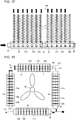
- FIG. 3 is a schematic side view illustrating the outdoor heat exchanger 107 according to Embodiment 1 of the present disclosure. Black arrows in FIG. 3 represent refrigerant flow when the outdoor heat exchanger 107 functions as an evaporator.
- the outdoor heat exchanger 107 accommodated in the outdoor unit 101 of the air-conditioning apparatus 100 exchanges heat between refrigerant and the outside air sucked through the air inlet 101b by the fan 90.
- the outdoor heat exchanger 107 is disposed below the fan 90.
- the outdoor heat exchanger 107 includes a plurality of fins 2, a plurality of heat-transfer tubes 1, and a refrigerant distributor 30.
- the fins 2 are disposed side by side with spaces therebetween.
- the heat-transfer tubes 1 are disposed side by side with each of the fins 2 interposed therebetween.
- the refrigerant distributor 30 is disposed horizontal to gravity. At least two outdoor heat exchangers 107 are disposed.
- the refrigerant distributor 30 has a double-pipe structure including an inner pipe 31 and outer pipes 32a and 32b. At least two outer pipes 32a and 32b are disposed such that the number of the outer pipes 32a and 32b is equal to that of the outdoor heat exchangers 107. A space 36 is formed between the outer pipes 32a and 32b adjacent to each other of a plurality of outer pipes 32a and 32b.
- One inner pipe 31 is disposed to be continuous through the plurality of outer pipes 32a and 32b.
- the heat-transfer tubes 1 are arrayed in a direction in which the outer pipes 32a and 32b extend and connected to the outer pipes 32a and 32b.
- the refrigerant distributor 30 thereby distributes refrigerant flowing into between the inner pipe 31 and the outer pipe 32a and into between the inner pipe 31 and the outer pipe 32b to the heat-transfer tubes 1.
- the refrigerant distributor 30 includes, separately, the outer pipe 32a, which is on the upstream side in the refrigerant distributor 30, and the outer pipe 32b, which is on the downstream side in the refrigerant distributor 30, whereas the refrigerant distributor 30 includes only one inner pipe 31 to be continuous through the outer pipes 32a and 32b.
- a direction in which the inner pipe 31 extends is kept horizontal.
- Refrigerant containing liquid refrigerant flows into the inner pipe 31 from one end of the inner pipe 31.
- a cap 35 is disposed at the most downstream end of the inner pipe 31 in a refrigerant flow when the outdoor heat exchanger 107 functions as an evaporator to seal the inner pipe 31.
- a refrigerant pipe 62 of the refrigeration cycle circuit is connected to the most upstream end of the inner pipe 31 in a refrigerant flow when the outdoor heat exchanger 107 functions as an evaporator.
- a plurality of refrigerant outlets 34 are formed at the inner pipe 31.
- the refrigerant outlets 34 are openings disposed side by side with spaces therebetween in the direction in which the inner pipe 31 extends in a plurality of double-pipe portions 33a and 33b.
- the double-pipe portion 33a has a double-pipe structure composed of the outer pipe 32a and the inner pipe 31.
- the double-pipe portion 33b has a double-pipe structure composed of the outer pipe 32b and the inner pipe 31.
- the inner pipe 31 has the refrigerant outlets 34 disposed side by side as described above, and thus two-phase gas-liquid refrigerant flows through the inner pipe 31 and passes through the refrigerant outlets 34 when the outdoor heat exchanger 107 functions as an evaporator.
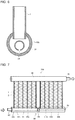
- FIG. 4 is a sectional view taken along line A-A in FIG. 3 illustrating an example of the refrigerant distributor 30 according to Embodiment 1 of the present disclosure.
- the refrigerant distributor 30 illustrated in FIG. 4 has a configuration in which the outer pipes 32a and 32b are made of rectangular pipes, the inner pipe 31 is made of a circular pipe, and the refrigerant outlets 34 are disposed to face downward.
- the outer pipes 32a and 32b are made of rectangular pipes, and thus the length of the refrigerant distributor 30 in the column direction can be reduced in the case of the heat-transfer tubes 1 made of flat tubes.
- FIG. 5 is a sectional view illustrating another example of the refrigerant distributor 30 according to Embodiment 1 of the present disclosure.
- the same configuration as that in the above embodiment is not described, and only its features are described.
- the refrigerant distributor 30 or header collecting pipes 40 and 41 can be disposed without steps.
- the frontal areas of the outdoor heat exchangers 107 can be increased.
- the joints in the heat-transfer tubes 1, which are flat tubes, are straight, and thus the heat-transfer tubes 1 can have uniform brazing margins. As a result, the ease of brazing is improved.
- FIG. 6 is a sectional view illustrating still another example of the refrigerant distributor 30 according to Embodiment 1 of the present disclosure.
- the refrigerant distributor 30 includes the outer pipes 32a and 32b and the inner pipe 31 made of circular pipes, and the refrigerant outlets 34 formed to face downward.
- the outer pipes 32a and 32b and the inner pipe 31 are made of circular pipes, and thus the refrigerant distributor 30 has excellent pressure resistance.
- the distances in the radial direction of sections orthogonal to the pipe-extending direction between the outer pipe 32a and the inner pipe 31 and between the outer pipe 32b and the inner pipe 31 are uniform. Thus, agitated refrigerant can be distributed to the heat-transfer tubes 1 with its homogeneous state maintained.
- Embodiment 1 the pipe shapes of the outer pipes 32a and 32b and the inner pipe 31 of the refrigerant distributor 30 are illustrated. However, the present disclosure is not limited to those shapes.
- Embodiment 1 only the example in which the refrigerant outlets 34 of the inner pipe 31 of the refrigerant distributor 30 face downward is described. However, this is merely an example, and the direction in which the refrigerant outlets 34 face is not limited thereto.
- the outdoor heat exchanger 107 including the refrigerant distributor 30 accommodated in the top-flow outdoor unit is described as merely an example. However, the configuration is not limited thereto.
- the outdoor heat exchanger 107 including the refrigerant distributor 30 may be accommodated as a heat exchanger of, for example, indoor units or side-flow outdoor units such as outdoor units of room air-conditioning apparatuses or packaged air-conditioning apparatuses.
- the refrigerant distributor 30 has a double-pipe structure including the inner pipe 31 and the outer pipes 32a and 32b.
- a plurality of outer pipes 32a and 32b are disposed, each of the plurality of outer pipes 32a and 32b being respectively the outer pipes 32a and 32b.
- the space 36 is formed between the outer pipes 32a and 32b adjacent to each other of the plurality of outer pipes 32a and 32b.
- One inner pipe 31 is disposed to be continuous through the plurality of outer pipes 32a and 32b.
- the plurality of heat-transfer tubes 1 are arrayed in the direction in which the outer pipes 32a and 32b extend and connected to the outer pipes 32a and 32b.
- the refrigerant distributor 30 thereby distributes refrigerant flowing into between the inner pipe 31 and the outer pipe 32a and into between the inner pipe 31 and the outer pipe 32b to the heat-transfer tubes 1.
- the refrigerant distributor 30 distributes refrigerant to the plurality of outdoor heat exchangers 107, the refrigerant flows through only the inner pipe 31 and the outer pipes 32a and 32b adjacent to each other. Thus, it is possible to reduce the amount of refrigerant.
- the space is formed between the outer pipes 32a and 32b adjacent to each other, and one inner pipe 31 is disposed to be continuous through the plurality of outer pipes 32a and 32b.
- the refrigerant distributor 30 is reduced in size, and it is possible to assemble the outdoor heat exchangers 107 with high density.
- the outdoor heat exchanger 107 functions as a condenser, it is possible to reduce impairment of heat exchange efficiency due to liquid refrigerant remaining inside the refrigerant distributor 30.
- the refrigerant distributor 30 has a small volume, and heat exchange efficiency is improved.
- the plurality of refrigerant outlets 34 are formed at the inner pipe 31.
- the refrigerant outlets 34 are openings disposed side by side with spaces therebetween in the direction in which the inner pipe 31 extends in the plurality of double-pipe portions 33a and 33b.
- the double-pipe portion 33a has a double-pipe structure composed of the outer pipe 32a and the inner pipe 31.
- the double-pipe portion 33b has a double-pipe structure composed of the outer pipe 32b and the inner pipe 31.
- two-phase gas-liquid refrigerant flows through the inner pipe 31 and passes through the refrigerant outlets 34 when the outdoor heat exchanger 107 functions as an evaporator. Agitated two-phase gas-liquid refrigerant then flows in the internal space of the outer pipe 32a of the double-pipe portion 33a, which is defined by the inner pipe 31 and the outer pipe 32a on the upstream side, and in the internal space of the outer pipe 32b of the double-pipe portion 33b, which is defined by the inner pipe 31 and the outer pipe 32b on the downstream side.
- refrigerant passes through the refrigerant outlets 34 and is agitated.
- the refrigerant flows like a homogeneous flow.
- the refrigerant distribution performance is improved, and it is possible to improve the performance of the outdoor heat exchanger 107.
- the outdoor heat exchanger 107 includes the refrigerant distributor 30.
- the refrigerant distributor 30 has a small volume, and heat exchange efficiency is improved.
- the air-conditioning apparatus 100 includes the outdoor heat exchanger 107.
- the inner pipe 31 of the refrigerant distributor 30 be disposed such that the direction in which the inner pipe 31 extends is horizontal and that refrigerant containing liquid refrigerant flow into the inner pipe 31 from one end of the inner pipe 31.
- liquid refrigerant can easily flow to the other end of the inner pipe 31, and thus refrigerant is distributed satisfactorily.
- the refrigerant distributor 30 has a small volume, and heat exchange efficiency is improved.
- FIG. 7 is a schematic side view illustrating an outdoor heat exchanger 107 according to Embodiment 2 of the present disclosure.
- the same configuration as that in the above embodiment is not described, and only its features are described.
- the plurality of outer pipes 32a and 32b of the refrigerant distributor 30 are separated and connected to the respective outdoor heat exchangers 107, and only the inner pipe 31 is continuous through and connected to the plurality of outer pipes 32a and 32b.
- Upper parts of the plurality of outdoor heat exchangers 107 are connected to a refrigerant pipe 61 via the header collecting pipe 40.
- the inner pipe 31 in each of the double-pipe portions 33a and the inner pipe 31 in each of the double-pipe portions 33b are separated and have different pipe diameters.
- the double-pipe portion 33a has a double-pipe structure composed of the outer pipe 32a and the inner pipe 31.
- the double-pipe portion 33b has a double-pipe structure composed of the outer pipe 32b and the inner pipe 31. Specifically, in the direction of white arrows in FIG.
- the pipe diameter of an inner pipe 31a in the double-pipe portion 33a on the upstream side is larger than the pipe diameter of an inner pipe 31b in the double-pipe portion 33b on the downstream side.
- the pipe diameter of the inner pipe 31b in the double-pipe portion 33b on the downstream side is smaller than the pipe diameter of the inner pipe 31a in the double-pipe portion 33a on the upstream side.
- refrigerant flow varies from annular flow to separated flow on the downstream side in the inner pipe 31b, where the refrigerant flow rate is lower than that in the vicinity of the inlet of the inner pipe 31a.
- the position where the pipe diameter of the inner pipe 31 is changed is determined on the basis of a common flow pattern map of refrigerant, such as a modified Baker chart, and the pipe diameter of the inner pipe 31 is changed such that most of the refrigerant flow in the inner pipe 31 does not become separated flow.
- FIG. 8 illustrates the relationships between flow states and distribution characteristics of refrigerant in the inner pipe 31 according to Embodiment 2 of the present disclosure.
- FIG. 8 illustrates the ratio between flow rates of the liquid refrigerant passing through the refrigerant outlets 34 when the refrigerant flow in the inner pipe 31 is annular flow in FIG. 8(A) and when the refrigerant flow in the inner pipe 31 is separated flow in FIG. 8(B) .
- the relationships in FIG. 8 result from tests and calculations performed by the inventors.
- the position closer to the refrigerant inlet is defined as A
- the position farther from the refrigerant inlet is defined as G in alphabetical order. Dashed lines in FIG.
- FIG. 8 represent the ranges in which the refrigerant outlets 34 affect refrigerant flow, and the refrigerant inside the dashed lines passes through the refrigerant outlets 34 and is distributed in a certain time.
- the flow pattern of refrigerant is annular flow in FIG. 8(A)
- a thin liquid film 5 is formed to cover the entire inner surface of the inner pipe 31, and the thin liquid film 5 has almost the same thickness at any position in the direction in which the inner pipe 31 extends.
- the same amount of liquid refrigerant is distributed through almost all of the refrigerant outlets 34.
- FIG. 9 is a schematic side view illustrating another example of the outdoor heat exchanger 107 according to Embodiment 2 of the present disclosure.
- the same configuration as that in the above embodiment is not described, and only its features are described.
- the inner pipe 31 is separated in the direction in which the inner pipe 31 extends, and each separate inner pipe 31 has a different pipe diameter. Specifically, in the directions of black arrows in FIG.
- the inner pipe 31a in the double-pipe portion 33a on the upstream side is separated in the direction in which the inner pipe 31a extends, and the pipe diameter of one separate inner pipe 31a on the upstream side is set to be larger than that of the other separate inner pipe 31a on the downstream side.
- the pipe diameter of the inner pipe 31a changes in the double-pipe portion 33a on the upstream side.
- This structure enables the pipe diameter of the inner pipe 31 to be finely changed on the basis of flow patterns and thus the refrigerant distribution performance to be improved.
- FIG. 10 is a schematic side view illustrating still another example of the outdoor heat exchanger 107 according to Embodiment 2 of the present disclosure.
- the outer pipes 32a and 32b are separated in the direction in which the inner pipe 31 extends and have different pipe diameters.
- the pipe diameter of the outer pipe 32a in the double-pipe portion 33a on the upstream side is larger than the pipe diameter of the outer pipe 32b in the double-pipe portion 33b on the downstream side.
- the pipe diameter of the inner pipe 31b in the double-pipe portion 33b on the downstream side is smaller than the pipe diameter of the inner pipe 31a in the double-pipe portion 33a on the upstream side
- the pipe diameter of the outer pipe 32b in the double-pipe portion 33b on the downstream side is smaller than the pipe diameter of the outer pipe 32a in the double-pipe portion 33a on the upstream side.
- FIG. 11 is a schematic side view illustrating still another example of the outdoor heat exchanger 107 according to Embodiment 2 of the present disclosure.
- the center of the outer pipe 32b in the double-pipe portion 33b on the downstream side is eccentrically upward relative to the center of the inner pipe 31b in the double-pipe portion 33b on the downstream side.
- the top of the outer pipe 32a in the double-pipe portion 33a on the upstream side and the top of the outer pipe 32b in the double-pipe portion 33b on the downstream side are aligned.
- the length of each of the parts of the heat-transfer tubes 1, which are flat tubes, inserted in the outer pipe 32a is equal to the length of each of the parts of the heat-transfer tubes 1, which are flat tubes, inserted in the outer pipe 32b.
- the brazing margins of the heat-transfer tubes 1, which are flat tubes, in the plurality of double-pipe portions 33a and 33b can be substantially uniform, and thus the ease of brazing is further improved.
- manufacturability is further improved.
- the outdoor heat exchanger 107 functions as a condenser, it is possible to reduce impairment of heat exchange efficiency because refrigerant liquid hardly remains inside the refrigerant distributor 30.
- the inner pipe 31 in each of the double-pipe portions 33a and the inner pipe 31 in each of the double-pipe portions 33b are separated and have different pipe diameters.
- the double-pipe portion 33a has a double-pipe structure composed of the outer pipe 32a and the inner pipe 31.
- the double-pipe portion 33b has a double-pipe structure composed of the outer pipe 32b and the inner pipe 31.
- This configuration enables the pipe diameter of the inner pipe 31 to be changed on the basis of the flow pattern of refrigerant flowing through the inner pipe 31 and thus the refrigerant distribution performance to be improved.
- the inner pipe 31 is separated in the direction in which the inner pipe 31 extends, and each separate inner pipe 31 has a different pipe diameter.
- This configuration enables the pipe diameter of the inner pipe 31 to be finely changed on the basis of the flow pattern of refrigerant flowing through the inner pipe 31 and thus the refrigerant distribution performance to be further improved.
- the outer pipes 32a and 32b are separated in the direction in which the inner pipe 31 extends and have different pipe diameters.
- FIG. 12 is a schematic side view illustrating an example of an outdoor heat exchanger 107 according to Embodiment 3 of the present disclosure.
- the same configurations as those in the above embodiments are not described, and only its features are described.
- the outer pipes 32a and 32b of the refrigerant distributor 30 are separated and connected to the respective outdoor heat exchangers 107.
- the inner pipe 31 has a bent portion 31c between the double-pipe portions 33a and 33b adjacent to each other of the plurality of double-pipe portions 33a and 33b.
- the double-pipe portion 33a has a double-pipe structure composed of the outer pipe 32a and the inner pipe 31.
- the double-pipe portion 33b has a double-pipe structure composed of the outer pipe 32b and the inner pipe 31.
- the inner pipe 31 connects the double-pipe portions 33a and 33b adjacent to each other to form an L shape.
- the inner pipe 31 is formed into the bent portion 31c having an L shape, and only the inner pipe 31 connects the outdoor heat exchangers 107 adjacent to each other.
- the bend radius of a bent pipe can be reduced. As a result, it is possible to increase the mounting areas of the outdoor heat exchangers 107 and to improve heat exchange efficiency.
- FIG. 13 is a schematic top view illustrating the example of the outdoor heat exchanger 107 according to Embodiment 3 of the present disclosure.
- FIG. 13 illustrates, as an example, the refrigerant distributor 30 in the case of the outdoor heat exchangers 107 disposed to form an L shape in top view.
- the configuration is not limited to only a configuration in which the outdoor heat exchangers 107 are disposed to form an L shape in top view.
- FIG. 14 is a schematic top view illustrating another example of the outdoor heat exchanger 107 according to Embodiment 3 of the present disclosure.
- the same configurations as those in the above embodiments are not described, and only its features are described.
- a similar effect can be achieved also in the case of the inner pipe 31 disposed to be bent to have an obtuse angle.
- the position of the inner pipe 31b, whose pipe diameter is reduced is not limited to the downstream side of the bent portion 31c, which is a bent connecting pipe.
- refrigerant flow easily becomes turbulent at a position immediately downstream of the bent portion 31c having, for example, an L shape of the inner pipe 31.
- the outdoor heat exchanger 107 functions as a condenser, it is possible to reduce impairment of heat exchange efficiency because refrigerant liquid hardly remains inside the refrigerant distributor 30.
- the inner pipe 31 has the bent portion 31c between the double-pipe portions 33a and 33b adjacent to each other of the plurality of double-pipe portions 33a and 33b.
- the double-pipe portion 33a has a double-pipe structure composed of the outer pipe 32a and the inner pipe 31.
- the double-pipe portion 33b has a double-pipe structure composed of the outer pipe 32b and the inner pipe 31.
- FIG. 15 is a schematic top view illustrating an example of an outdoor heat exchanger 107 according to Embodiment 4 of the present disclosure.
- a set of the plurality of refrigerant outlets 34 in each of the double-pipe portions 33a and a set of the plurality of refrigerant outlets 34 in each of the double-pipe portions 33b are separated and have different outlet diameters.
- the double-pipe portion 33a has a double-pipe structure composed of the outer pipe 32a and the inner pipe 31.
- the double-pipe portion 33b has a double-pipe structure composed of the outer pipe 32b and the inner pipe 31.
- the outlet diameter of the refrigerant outlets 34 in the double-pipe portion 33a on the upstream side is set to be smaller than the outlet diameter of the refrigerant outlets 34 in the double-pipe portion 33b on the downstream side. More specifically, in the plurality of outdoor heat exchangers 107 connected only by the bent portion 31c having an L shape of the inner pipe 31, the outlet diameter of the refrigerant outlets 34 in the double-pipe portion 33a on the upstream side is smaller than the outlet diameter of the refrigerant outlets 34 in the double-pipe portion 33b on the downstream side.
- the configuration is not limited thereto.
- the pipe diameter of the inner pipe 31b in the double-pipe portion 33b on the downstream side be smaller than the pipe diameter of the inner pipe 31a in the double-pipe portion 33a on the upstream side. In this case, the influence of flow resistance generated due to pipe contraction at the part where the pipe diameter of the inner pipe 31 is changed can be reduced by the pipe diameter difference in the inner pipe 31.
- a set of the refrigerant outlets 34, which are a plurality of openings, in each of the double-pipe portions 33a and a set of the refrigerant outlets 34, which are a plurality of openings, in each of the double-pipe portions 33b are separated and have different outlet diameters.
- the double-pipe portion 33a has a double-pipe structure composed of the outer pipe 32a and the inner pipe 31.
- the double-pipe portion 33b has a double-pipe structure composed of the outer pipe 32b and the inner pipe 31.
- FIG. 16 is a schematic side view illustrating an example of an outdoor heat exchanger 107 according to Embodiment 5 of the present disclosure.
- a set of the plurality of refrigerant outlets 34 in each of the double-pipe portions 33a and a set of the plurality of refrigerant outlets 34 in each of the double-pipe portions 33b are separated and formed at different positions.
- the double-pipe portion 33a has a double-pipe structure composed of the outer pipe 32a and the inner pipe 31.
- the double-pipe portion 33b has a double-pipe structure composed of the outer pipe 32b and the inner pipe 31.
- the positions of the refrigerant outlets 34 disposed in the inner pipe 31a in the double-pipe portion 33a on the upstream side are higher than the positions of the refrigerant outlets 34 disposed in the double-pipe portion 33b on the downstream side.
- this structure enables liquid refrigerant to flow sufficiently to the downstream side in the refrigerant distributor 30 at a low refrigerant flow velocity.
- a set of the refrigerant outlets 34, which are a plurality of openings, in each of the double-pipe portions 33a and a set of the refrigerant outlets 34, which are a plurality of openings, in each of the double-pipe portions 33b are separated and formed at different positions.
- the double-pipe portion 33a has a double-pipe structure composed of the outer pipe 32a and the inner pipe 31.
- the double-pipe portion 33b has a double-pipe structure composed of the outer pipe 32b and the inner pipe 31.
- This configuration enables liquid refrigerant to flow sufficiently to the downstream side in the refrigerant distributor 30 at a low refrigerant flow velocity.
- FIG. 17 is a schematic side view illustrating an example of an outdoor heat exchanger 107 according to Embodiment 6 of the present disclosure.
- the plurality of refrigerant outlets 34 are separated in the direction in which the inner pipe 31 extends, and each separate set of the refrigerant outlets 34 has a different outlet diameter.
- the plurality of refrigerant outlets 34 are separated in the direction in which the inner pipe 31 extends, and each separate set of the refrigerant outlets 34 has a different up-down position.
- the region in which the plurality of refrigerant outlets 34 are formed is separated in the direction in which the inner pipe 31 extends.
- the region in which the plurality of refrigerant outlets 34 are formed includes the region in which the small refrigerant outlets 34 at lower positions and the large refrigerant outlets 34 at higher positions are formed.
- the region in which the plurality of refrigerant outlets 34 are formed includes the region in which the large refrigerant outlets 34 at lower positions and the small refrigerant outlets 34 at higher positions are formed.
- the plurality of outdoor heat exchangers 107 are connected only by the inner pipe 31.
- At least two kinds of the refrigerant outlets 34 whose up-down positions are different from each other and outlet diameters are different from each other, are formed at the inner pipe 31 in each of the double-pipe portions 33a on the upstream side and the inner pipe 31 in each of the double-pipe portions 33b on the downstream side. More specifically, the outlet diameter of the refrigerant outlets 34 at lower positions in the double-pipe portion 33a on the upstream side is smaller than the outlet diameter of the refrigerant outlets 34 at lower positions in the double-pipe portion 33b on the downstream side. On the other hand, the outlet diameter of the refrigerant outlets 34 at higher positions in the double-pipe portion 33a on the upstream side is larger than the outlet diameter of the refrigerant outlets 34 at higher positions in the double-pipe portion 33b on the downstream side.
- refrigerant flows like separated flow at a low refrigerant flow velocity.
- the outlet diameter of the refrigerant outlets 34 at lower positions in the double-pipe portion 33a on the upstream side is small, it is possible to inhibit a large amount of liquid refrigerant from being distributed to the refrigerant outlets 34 at lower positions in the double-pipe portion 33a on the upstream side.
- liquid refrigerant can flow sufficiently into the double-pipe portion 33b on the downstream side.
- refrigerant flows like annular flow at a high refrigerant flow velocity.
- liquid refrigerant can be distributed through the refrigerant outlets 34 at higher positions and lower positions in the double-pipe portion 33a on the upstream side and the refrigerant outlets 34 at higher positions and lower positions in the double-pipe portion 33b on the downstream side.
- the refrigerant distribution performance can be improved. That is, the refrigerant distribution performance can be improved under a wide range of operational conditions.
- the refrigerant outlets 34 which are a plurality of openings, are separated in the direction in which the inner pipe 31 extends, and each separate set of the refrigerant outlets 34 has a different outlet diameter.
- the refrigerant distribution performance can be improved according to refrigerant flow velocities under a wide range of operational conditions.
- the refrigerant outlets 34 which are a plurality of openings, are separated in the direction in which the inner pipe 31 extends, and each separate set of the refrigerant outlets 34 has a different up-down position.
- the refrigerant distribution performance can be improved according to refrigerant flow velocities under a wide range of operational conditions.
- the region in which the refrigerant outlets 34, which are a plurality of openings, are formed is separated in the direction in which the inner pipe 31 extends.
- the region in which the refrigerant outlets 34 are formed includes the region in which the small refrigerant outlets 34 at lower positions and the large refrigerant outlets 34 at higher positions are formed, and the region in which the large refrigerant outlets 34 at lower positions and the small refrigerant outlets 34 at higher positions are formed.
- refrigerant flows like separated flow at a low refrigerant flow velocity.
- the outlet diameter of the refrigerant outlets 34 at lower positions on the upstream side is small, it is possible to inhibit an excessive amount of liquid refrigerant from being distributed to the upstream side.
- liquid refrigerant can flow sufficiently to the downstream side.
- refrigerant flows like annular flow at a high refrigerant flow velocity.
- liquid refrigerant can be distributed through the refrigerant outlets 34 at higher positions and lower positions on the upstream side and the refrigerant outlets 34 at higher positions and lower positions on the downstream side.
- the refrigerant distribution performance can be improved. That is, the refrigerant distribution performance can be improved according to refrigerant flow velocities under a wide range of operational conditions.
- FIG. 18 is a schematic side view illustrating an example of an outdoor heat exchanger 107 according to Embodiment 7 of the present disclosure.
- FIG. 18 illustrates two pairs of the outdoor heat exchangers 107 connected only by the respective bent portions 31c having an L shape of the inner pipe 31.
- the four outdoor heat exchangers 107 are disposed to surround the fan 90.
- the outdoor heat exchangers 107 are connected only by the bent portions 31c having an L shape of the inner pipe 31, the outdoor heat exchangers 107 can be disposed around the fan 90 with high density, and thus the heat transfer areas of the outdoor heat exchangers 107 can be increased. As a result, it is possible to improve energy efficiency.
- the pipe diameter of the inner pipe 31 in the outdoor heat exchangers 107 on the downstream side is reduced, and thus refrigerant flow velocity can be increased, the flow pattern of refrigerant becomes similar to annular flow, and the refrigerant distribution performance can be also improved.
- FIG. 19 is a schematic side view illustrating another example of the outdoor heat exchanger 107 according to Embodiment 7 of the present disclosure.
- FIG. 18 illustrates two pairs of the outdoor heat exchangers 107 connected only by the respective bent portions 31c having an L shape of the inner pipe 31, the configuration is not limited thereto.
- the four outdoor heat exchangers 107 may be connected in series only by the respective bent portions 31c having an L shape of the inner pipe 31.
- the length of the refrigerant distributor 30 in the pipe-extending direction is large.
- the difference between the flow velocity of refrigerant flowing through the inner pipes 31a on the upstream side of the refrigerant distributor 30 and the flow velocity of refrigerant flowing through the inner pipes 31b on the downstream side of the refrigerant distributor 30 is large.
- refrigerant flow in the inner pipes 31b on the downstream side easily becomes separated flow.
- the effect of improving the refrigerant distribution performance resulting from reductions in the pipe diameters of the inner pipes 31b on the downstream side is particularly large.
- Embodiment 1 to Embodiment 7 of the present disclosure may be combined or may be applied to other parts.
Landscapes
- Engineering & Computer Science (AREA)
- Mechanical Engineering (AREA)
- General Engineering & Computer Science (AREA)
- Physics & Mathematics (AREA)
- Thermal Sciences (AREA)
- Chemical & Material Sciences (AREA)
- Combustion & Propulsion (AREA)
- Heat-Exchange Devices With Radiators And Conduit Assemblies (AREA)
Abstract
Description
- The present disclosure relates to a refrigerant distributor, a heat exchanger, and an air-conditioning apparatus in which, when a heat exchanger functions as an evaporator, two-phase gas-liquid refrigerant flows through the refrigerant distributor.
- In existing air-conditioning apparatuses, liquid refrigerant condensed by a heat exchanger that functions as a condenser and that is accommodated in an indoor unit is decompressed by an expansion device. The refrigerant in a two-phase gas-liquid state in which gas refrigerant and liquid refrigerant are mixed together then flows into a heat exchanger that functions as an evaporator and that is accommodated in an outdoor unit. When two-phase gas-liquid refrigerant flows into a heat exchanger that functions as an evaporator, the performance of distributing the refrigerant to the heat exchanger is impaired. For example, there is a method for improving refrigerant distribution performance. In the method, to improve refrigerant distribution performance, flat tubes of a heat exchanger accommodated in an outdoor unit are disposed vertically upward, and a refrigerant distributor is disposed horizontally. Thus, the effect of gravity is reduced, and the refrigerant distribution performance is improved. However, even if a refrigerant distributor is horizontally disposed as described above, for example, there arises a problem in that the distribution performance fluctuates, depending on the flow rate of the refrigerant flowing in the refrigerant distributor or the refrigerant quality. For this reason, there arises a problem in that only a slight deviation of a value of a refrigerant flow condition from a design center value impairs the distribution performance and the heat exchange performance of a heat exchanger and thus causes an impairment in energy efficiency.
- To solve such a problem, a technique for improving refrigerant distribution performance is proposed (for example, see Patent Literature 1). In the technique, a refrigerant distributor has a double-pipe structure, a plurality of refrigerant outlets are disposed side by side in an inner pipe, and the refrigerant distribution performance is improved. Citation List
- Patent Literature 1: Japanese Unexamined Patent Application Publication No.
2015-203506 - In the technique in
Patent Literature 1, in the case of heat-transfer tubes made of flat tubes, an outer pipe whose width is at least larger than the length of the major axis of each flat tube has to be used. For this reason, there arises a problem of the outer pipe of the double pipe having a large volume. In addition, there arises a problem in that heat exchange efficiency is impaired due to a large amount of refrigerant liquid remaining in the refrigerant distributor during a condensing operation. - The present disclosure is made to overcome the above problems, and an object of the refrigerant distributor of the present disclosure is to provide a refrigerant distributor that has a small volume and with which heat exchange efficiency is improved, a heat exchanger, and an air-conditioning apparatus.
- A refrigerant distributor according to an embodiment of the present disclosure has a double-pipe structure including an inner pipe and an outer pipe. A plurality of outer pipes are disposed, each of the plurality of outer pipes being the outer pipe. A space is formed between adjacent ones of the plurality of outer pipes. The inner pipe is disposed to be continuous through the plurality of outer pipes. A plurality of heat-transfer tubes are arrayed in a direction in which the outer pipe extends and connected to the outer pipe. The refrigerant distributer distributes refrigerant flowing into between the inner pipe and the outer pipe to the plurality of heat-transfer tubes.
- A heat exchanger according to another embodiment of the present disclosure includes the refrigerant distributor.
- An air-conditioning apparatus according to still another embodiment of the present disclosure includes the heat exchanger. The direction in which the inner pipe of the refrigerant distributor of the heat exchanger extends is kept horizontal, and refrigerant containing liquid refrigerant flows into the inner pipe from one end of the inner pipe.
- In the refrigerant distributor, the heat exchanger, and the air-conditioning apparatus according to the embodiments of the present disclosure, the plurality of outer pipes are disposed, the space is formed between adjacent ones of the plurality of outer pipes, and the inner pipe is disposed to be continuous through the plurality of outer pipes. Thus, when the refrigerant distributor distributes refrigerant to the plurality of heat exchangers, the refrigerant flows through only the inner pipe and the outer pipes adjacent to each other. As a result, it is possible to reduce the amount of refrigerant. In addition, the space is formed between the outer pipes adjacent to each other, and the inner pipe is disposed to be continuous through the plurality of outer pipes. Thus, the refrigerant distributor is reduced in size, and it is possible to assemble the heat exchangers with high density. In addition, when the heat exchanger functions as a condenser, it is possible to reduce impairment of heat exchange efficiency due to liquid refrigerant remaining inside the refrigerant distributor. Thus, the refrigerant distributor has a small volume, and heat exchange efficiency is improved.
-
- FIG. 1
- is a diagram of a refrigerant circuit illustrating an air-conditioning apparatus according to
Embodiment 1 of the present disclosure. - FIG. 2
- is a side view illustrating an outdoor unit of the air-conditioning apparatus according to
Embodiment 1 of the present disclosure. - FIG. 3
- is a schematic side view illustrating a heat exchanger according to
Embodiment 1 of the present disclosure. - FIG. 4
- is a sectional view taken along line A-A in
FIG. 3 illustrating an example of a refrigerant distributor according toEmbodiment 1 of the present disclosure. - FIG. 5
- is a sectional view illustrating another example of the refrigerant distributor according to
Embodiment 1 of the present disclosure. - FIG. 6
- is a sectional view illustrating still another example of the refrigerant distributor according to
Embodiment 1 of the present disclosure. - FIG. 7
- is a schematic side view illustrating a heat exchanger according to
Embodiment 2 of the present disclosure. - FIG. 8
- illustrates the relationships between flow states and distribution characteristics of refrigerant in an inner pipe according to
Embodiment 2 of the present disclosure. - FIG. 9
- is a schematic side view illustrating another example of the heat exchanger according to
Embodiment 2 of the present disclosure. - FIG. 10
- is a schematic side view illustrating still another example of the heat exchanger according to
Embodiment 2 of the present disclosure. - FIG. 11
- is a schematic side view illustrating still another example of the heat exchanger according to
Embodiment 2 of the present disclosure. - FIG. 12
- is a schematic side view illustrating an example of a heat exchanger according to
Embodiment 3 of the present disclosure. - FIG. 13
- is a schematic top view illustrating the example of the heat exchanger according to
Embodiment 3 of the present disclosure. - FIG. 14
- is a schematic top view illustrating another example of the heat exchanger according to
Embodiment 3 of the present disclosure. - FIG. 15
- is a schematic top view illustrating an example of a heat exchanger according to Embodiment 4 of the present disclosure.
- FIG. 16
- is a schematic side view illustrating an example of a heat exchanger according to
Embodiment 5 of the present disclosure. - FIG. 17
- is a schematic side view illustrating an example of a heat exchanger according to Embodiment 6 of the present disclosure.
- FIG. 18
- is a schematic side view illustrating an example of a heat exchanger according to Embodiment 7 of the present disclosure.
- FIG. 19
- is a schematic side view illustrating another example of the heat exchanger according to Embodiment 7 of the present disclosure.
- Embodiments of the present disclosure will be described below with reference to the drawings. In the drawings, components having the same reference signs are the same or equivalent components, and this applies to the whole description. In the sectional views, hatching is omitted as appropriate in view of recognizability. In addition, the forms of the components in the whole description are merely examples, and the forms of the components are not limited to those in the description.
-
FIG. 1 is a diagram of a refrigerant circuit illustrating an air-conditioning apparatus 100 according toEmbodiment 1 of the present disclosure. In the air-conditioning apparatus 100 illustrated inFIG. 1 , anoutdoor unit 101 and anindoor unit 102 are connected by agas refrigerant pipe 103 and a liquidrefrigerant pipe 104. - The
outdoor unit 101 includes acompressor 105, a four-way valve 106, anoutdoor heat exchanger 107, and anexpansion valve 108. - The
compressor 105 compresses and discharges suctioned refrigerant. Thecompressor 105 may vary the amount of refrigerant sent by thecompressor 105 per unit time by freely varying operating frequency with, for example, an inverter circuit. - The four-
way valve 106 is a valve that switches between, for example, a refrigerant flow in a cooling operation and a refrigerant flow in a heating operation. - The
outdoor heat exchanger 107 exchanges heat between refrigerant and outdoor air. Theoutdoor heat exchanger 107 functions as a condenser in the cooling operation and condenses and liquifies refrigerant. Theoutdoor heat exchanger 107 functions as an evaporator in the heating operation and evaporates and gasifies refrigerant. - The
expansion valve 108 is a flow control valve and decompresses and expands refrigerant. For example, in the case of theexpansion valve 108 composed of an electronic expansion valve, the opening degree of theexpansion valve 108 can be controlled by instructions from a controller (not illustrated) or other devices. - The
indoor unit 102 includes anindoor heat exchanger 109. For example, theindoor heat exchanger 109 exchanges heat between air-conditioning target air and refrigerant. Theindoor heat exchanger 109 functions as an evaporator in the cooling operation and evaporates and gasifies refrigerant. Theindoor heat exchanger 109 functions as a condenser in the heating operation and condenses and liquifies refrigerant. - As described above, the configuration of the air-
conditioning apparatus 100 enables refrigerant flows to be switched with the four-way valve 106 of theoutdoor unit 101, and thus the cooling operation and the heating operation can be performed. -
FIG. 2 is a side view illustrating theoutdoor unit 101 of the air-conditioning apparatus 100 according toEmbodiment 1 of the present disclosure. Dashed arrows inFIG. 2 represent airflow. - The
outdoor unit 101 of the air-conditioning apparatus 100 accommodates theoutdoor heat exchanger 107. Theoutdoor unit 101 of the air-conditioning apparatus 100 is a top-flow outdoor unit. A refrigeration cycle circuit is formed by circulating refrigerant between theoutdoor unit 101 and theindoor unit 102. Theoutdoor unit 101 is used as, for example, an outdoor unit of a multi-air-conditioning apparatus for buildings and is installed on a building roof or in other places. - As illustrated in
FIG. 2 , theoutdoor unit 101 includes acasing 101a, which is shaped like a box. Anair inlet 101b, which is open in a side of thecasing 101a, is formed in theoutdoor unit 101. Theoutdoor unit 101 includes theoutdoor heat exchanger 107, which is disposed in thecasing 101a along theair inlet 101b. Anair outlet 101c, which is open in the top of thecasing 101a, is formed in theoutdoor unit 101. Theoutdoor unit 101 includes afan guard 101d, which is disposed to cover theair outlet 101c and through which air flows. Theoutdoor unit 101 includes a top-flow fan 90, which is disposed inside thefan guard 101d and sucks outside air through theair inlet 101b and discharges exhaust air that has been subjected to heat exchange from theair outlet 101c. -
FIG. 3 is a schematic side view illustrating theoutdoor heat exchanger 107 according toEmbodiment 1 of the present disclosure. Black arrows inFIG. 3 represent refrigerant flow when theoutdoor heat exchanger 107 functions as an evaporator. - The
outdoor heat exchanger 107 accommodated in theoutdoor unit 101 of the air-conditioning apparatus 100 exchanges heat between refrigerant and the outside air sucked through theair inlet 101b by thefan 90. Theoutdoor heat exchanger 107 is disposed below thefan 90. - As illustrated in
FIG. 3 , theoutdoor heat exchanger 107 includes a plurality offins 2, a plurality of heat-transfer tubes 1, and arefrigerant distributor 30. Thefins 2 are disposed side by side with spaces therebetween. The heat-transfer tubes 1 are disposed side by side with each of thefins 2 interposed therebetween. Therefrigerant distributor 30 is disposed horizontal to gravity. At least twooutdoor heat exchangers 107 are disposed. - As illustrated in
FIG. 3 , therefrigerant distributor 30 has a double-pipe structure including aninner pipe 31 andouter pipes outer pipes outer pipes outdoor heat exchangers 107. Aspace 36 is formed between theouter pipes outer pipes inner pipe 31 is disposed to be continuous through the plurality ofouter pipes transfer tubes 1 are arrayed in a direction in which theouter pipes outer pipes refrigerant distributor 30 thereby distributes refrigerant flowing into between theinner pipe 31 and theouter pipe 32a and into between theinner pipe 31 and theouter pipe 32b to the heat-transfer tubes 1. - That is, the
refrigerant distributor 30 includes, separately, theouter pipe 32a, which is on the upstream side in therefrigerant distributor 30, and theouter pipe 32b, which is on the downstream side in therefrigerant distributor 30, whereas therefrigerant distributor 30 includes only oneinner pipe 31 to be continuous through theouter pipes inner pipe 31 extends is kept horizontal. Refrigerant containing liquid refrigerant flows into theinner pipe 31 from one end of theinner pipe 31. Acap 35 is disposed at the most downstream end of theinner pipe 31 in a refrigerant flow when theoutdoor heat exchanger 107 functions as an evaporator to seal theinner pipe 31. Arefrigerant pipe 62 of the refrigeration cycle circuit is connected to the most upstream end of theinner pipe 31 in a refrigerant flow when theoutdoor heat exchanger 107 functions as an evaporator. - With this structure, it is possible to reduce the outer pipe volume of the part where the
outdoor heat exchangers 107 are connected, the part not contributing to refrigerant distribution performance. Accordingly, it is possible to reduce the amount of refrigerant flowing through therefrigerant distributor 30. In addition, only theinner pipe 31 is continuous through and connects the twoouter pipes outdoor heat exchangers 107 can be easily bent by bending only theinner pipe 31. As a result, it is possible to assemble theoutdoor heat exchangers 107 with high density. - A plurality of
refrigerant outlets 34 are formed at theinner pipe 31. Therefrigerant outlets 34 are openings disposed side by side with spaces therebetween in the direction in which theinner pipe 31 extends in a plurality of double-pipe portions pipe portion 33a has a double-pipe structure composed of theouter pipe 32a and theinner pipe 31. The double-pipe portion 33b has a double-pipe structure composed of theouter pipe 32b and theinner pipe 31. Theinner pipe 31 has therefrigerant outlets 34 disposed side by side as described above, and thus two-phase gas-liquid refrigerant flows through theinner pipe 31 and passes through therefrigerant outlets 34 when theoutdoor heat exchanger 107 functions as an evaporator. Agitated two-phase gas-liquid refrigerant then flows in the space defined by theinner pipe 31 and theouter pipe 32a on the upstream side, and in the space defined by theinner pipe 31 and theouter pipe 32b on the downstream side. As described above, refrigerant passes through therefrigerant outlets 34, and two-phase gas-liquid refrigerant is agitated. Thus, the refrigerant flows like a homogeneous flow. As a result, the refrigerant distribution performance is improved, and it is possible to improve the performance of theoutdoor heat exchanger 107. In addition, when theoutdoor heat exchanger 107 functions as a condenser, it is possible to reduce impairment of heat exchange efficiency because refrigerant liquid hardly remains inside therefrigerant distributor 30. -
FIG. 4 is a sectional view taken along line A-A inFIG. 3 illustrating an example of therefrigerant distributor 30 according toEmbodiment 1 of the present disclosure. Therefrigerant distributor 30 illustrated inFIG. 4 has a configuration in which theouter pipes inner pipe 31 is made of a circular pipe, and therefrigerant outlets 34 are disposed to face downward. Theouter pipes refrigerant distributor 30 in the column direction can be reduced in the case of the heat-transfer tubes 1 made of flat tubes. -
FIG. 5 is a sectional view illustrating another example of therefrigerant distributor 30 according toEmbodiment 1 of the present disclosure. Hereinafter, the same configuration as that in the above embodiment is not described, and only its features are described. As illustrated inFIG. 5 , when theoutdoor heat exchangers 107 are disposed in two columns, therefrigerant distributor 30 orheader collecting pipes outdoor heat exchangers 107 can be increased. In addition, the joints in the heat-transfer tubes 1, which are flat tubes, are straight, and thus the heat-transfer tubes 1 can have uniform brazing margins. As a result, the ease of brazing is improved. -
FIG. 6 is a sectional view illustrating still another example of therefrigerant distributor 30 according toEmbodiment 1 of the present disclosure. Hereinafter, the same configuration as that in the above embodiment is not described, and only its features are described. As illustrated inFIG. 6 , therefrigerant distributor 30 includes theouter pipes inner pipe 31 made of circular pipes, and therefrigerant outlets 34 formed to face downward. Theouter pipes inner pipe 31 are made of circular pipes, and thus therefrigerant distributor 30 has excellent pressure resistance. In addition, the distances in the radial direction of sections orthogonal to the pipe-extending direction between theouter pipe 32a and theinner pipe 31 and between theouter pipe 32b and theinner pipe 31 are uniform. Thus, agitated refrigerant can be distributed to the heat-transfer tubes 1 with its homogeneous state maintained. - In
Embodiment 1, the pipe shapes of theouter pipes inner pipe 31 of therefrigerant distributor 30 are illustrated. However, the present disclosure is not limited to those shapes. In addition, inEmbodiment 1, only the example in which therefrigerant outlets 34 of theinner pipe 31 of therefrigerant distributor 30 face downward is described. However, this is merely an example, and the direction in which therefrigerant outlets 34 face is not limited thereto. In addition, inEmbodiment 1, theoutdoor heat exchanger 107 including therefrigerant distributor 30 accommodated in the top-flow outdoor unit is described as merely an example. However, the configuration is not limited thereto. Theoutdoor heat exchanger 107 including therefrigerant distributor 30 may be accommodated as a heat exchanger of, for example, indoor units or side-flow outdoor units such as outdoor units of room air-conditioning apparatuses or packaged air-conditioning apparatuses. - According to
Embodiment 1, therefrigerant distributor 30 has a double-pipe structure including theinner pipe 31 and theouter pipes outer pipes outer pipes outer pipes space 36 is formed between theouter pipes outer pipes inner pipe 31 is disposed to be continuous through the plurality ofouter pipes transfer tubes 1 are arrayed in the direction in which theouter pipes outer pipes refrigerant distributor 30 thereby distributes refrigerant flowing into between theinner pipe 31 and theouter pipe 32a and into between theinner pipe 31 and theouter pipe 32b to the heat-transfer tubes 1. - With this configuration, when the
refrigerant distributor 30 distributes refrigerant to the plurality ofoutdoor heat exchangers 107, the refrigerant flows through only theinner pipe 31 and theouter pipes outer pipes inner pipe 31 is disposed to be continuous through the plurality ofouter pipes refrigerant distributor 30 is reduced in size, and it is possible to assemble theoutdoor heat exchangers 107 with high density. In addition, when theoutdoor heat exchanger 107 functions as a condenser, it is possible to reduce impairment of heat exchange efficiency due to liquid refrigerant remaining inside therefrigerant distributor 30. Thus, therefrigerant distributor 30 has a small volume, and heat exchange efficiency is improved. - According to
Embodiment 1, the plurality ofrefrigerant outlets 34 are formed at theinner pipe 31. Therefrigerant outlets 34 are openings disposed side by side with spaces therebetween in the direction in which theinner pipe 31 extends in the plurality of double-pipe portions pipe portion 33a has a double-pipe structure composed of theouter pipe 32a and theinner pipe 31. The double-pipe portion 33b has a double-pipe structure composed of theouter pipe 32b and theinner pipe 31. - With this configuration, two-phase gas-liquid refrigerant flows through the
inner pipe 31 and passes through therefrigerant outlets 34 when theoutdoor heat exchanger 107 functions as an evaporator. Agitated two-phase gas-liquid refrigerant then flows in the internal space of theouter pipe 32a of the double-pipe portion 33a, which is defined by theinner pipe 31 and theouter pipe 32a on the upstream side, and in the internal space of theouter pipe 32b of the double-pipe portion 33b, which is defined by theinner pipe 31 and theouter pipe 32b on the downstream side. As described above, refrigerant passes through therefrigerant outlets 34 and is agitated. Thus, the refrigerant flows like a homogeneous flow. As a result, the refrigerant distribution performance is improved, and it is possible to improve the performance of theoutdoor heat exchanger 107. - According to
Embodiment 1, theoutdoor heat exchanger 107 includes therefrigerant distributor 30. - With this configuration, in the
outdoor heat exchanger 107 including therefrigerant distributor 30, therefrigerant distributor 30 has a small volume, and heat exchange efficiency is improved. - According to
Embodiment 1, the air-conditioning apparatus 100 includes theoutdoor heat exchanger 107. In particular, it is preferable that theinner pipe 31 of therefrigerant distributor 30 be disposed such that the direction in which theinner pipe 31 extends is horizontal and that refrigerant containing liquid refrigerant flow into theinner pipe 31 from one end of theinner pipe 31. In this case, liquid refrigerant can easily flow to the other end of theinner pipe 31, and thus refrigerant is distributed satisfactorily. - With this configuration, in the air-
conditioning apparatus 100 including theoutdoor heat exchanger 107, therefrigerant distributor 30 has a small volume, and heat exchange efficiency is improved. -
FIG. 7 is a schematic side view illustrating anoutdoor heat exchanger 107 according toEmbodiment 2 of the present disclosure. Hereinafter, the same configuration as that in the above embodiment is not described, and only its features are described. As illustrated inFIG. 7 , the plurality ofouter pipes refrigerant distributor 30 are separated and connected to the respectiveoutdoor heat exchangers 107, and only theinner pipe 31 is continuous through and connected to the plurality ofouter pipes outdoor heat exchangers 107 are connected to arefrigerant pipe 61 via theheader collecting pipe 40. - The
inner pipe 31 in each of the double-pipe portions 33a and theinner pipe 31 in each of the double-pipe portions 33b are separated and have different pipe diameters. The double-pipe portion 33a has a double-pipe structure composed of theouter pipe 32a and theinner pipe 31. The double-pipe portion 33b has a double-pipe structure composed of theouter pipe 32b and theinner pipe 31. Specifically, in the direction of white arrows inFIG. 7 , in which two-phase gas-liquid refrigerant flows through theinner pipe 31 from therefrigerant pipe 62 when theoutdoor heat exchanger 107 functions as an evaporator, the pipe diameter of aninner pipe 31a in the double-pipe portion 33a on the upstream side is larger than the pipe diameter of aninner pipe 31b in the double-pipe portion 33b on the downstream side. In other words, the pipe diameter of theinner pipe 31b in the double-pipe portion 33b on the downstream side is smaller than the pipe diameter of theinner pipe 31a in the double-pipe portion 33a on the upstream side. - With this structure, refrigerant flow varies from annular flow to separated flow on the downstream side in the
inner pipe 31b, where the refrigerant flow rate is lower than that in the vicinity of the inlet of theinner pipe 31a. Thus, it is possible to reduce impairment of the performance of distributing the refrigerant passing through therefrigerant outlets 34. The position where the pipe diameter of theinner pipe 31 is changed is determined on the basis of a common flow pattern map of refrigerant, such as a modified Baker chart, and the pipe diameter of theinner pipe 31 is changed such that most of the refrigerant flow in theinner pipe 31 does not become separated flow. -
FIG. 8 illustrates the relationships between flow states and distribution characteristics of refrigerant in theinner pipe 31 according toEmbodiment 2 of the present disclosure.FIG. 8 illustrates the ratio between flow rates of the liquid refrigerant passing through therefrigerant outlets 34 when the refrigerant flow in theinner pipe 31 is annular flow inFIG. 8(A) and when the refrigerant flow in theinner pipe 31 is separated flow inFIG. 8(B) . The relationships inFIG. 8 result from tests and calculations performed by the inventors. In therefrigerant outlets 34 inFIG. 8 , the position closer to the refrigerant inlet is defined as A, and the position farther from the refrigerant inlet is defined as G in alphabetical order. Dashed lines inFIG. 8 represent the ranges in which therefrigerant outlets 34 affect refrigerant flow, and the refrigerant inside the dashed lines passes through therefrigerant outlets 34 and is distributed in a certain time. When the flow pattern of refrigerant is annular flow inFIG. 8(A) , athin liquid film 5 is formed to cover the entire inner surface of theinner pipe 31, and thethin liquid film 5 has almost the same thickness at any position in the direction in which theinner pipe 31 extends. Thus, the same amount of liquid refrigerant is distributed through almost all of therefrigerant outlets 34. - On the other hand, when the flow pattern of refrigerant is separated flow in
FIG. 8(B) , a refrigerant liquid film 6 is thicker than thethin liquid film 5 in annular flow. In addition, a large amount of liquid refrigerant is distributed in a lower portion in theinner pipe 31 due to gravity. Thus, the amounts of liquid refrigerant distributed through therefrigerant outlets 34 are larger toward the refrigerant inlet. As a result, the refrigerant distribution performance is impaired, and impairment of heat exchange efficiency is caused. -
FIG. 9 is a schematic side view illustrating another example of theoutdoor heat exchanger 107 according toEmbodiment 2 of the present disclosure. Hereinafter, the same configuration as that in the above embodiment is not described, and only its features are described. As illustrated inFIG. 9 , theinner pipe 31 is separated in the direction in which theinner pipe 31 extends, and each separateinner pipe 31 has a different pipe diameter. Specifically, in the directions of black arrows inFIG. 9 , in which two-phase gas-liquid refrigerant flows through theinner pipe 31 when theoutdoor heat exchanger 107 functions as an evaporator, theinner pipe 31a in the double-pipe portion 33a on the upstream side is separated in the direction in which theinner pipe 31a extends, and the pipe diameter of one separateinner pipe 31a on the upstream side is set to be larger than that of the other separateinner pipe 31a on the downstream side. - As described above, the pipe diameter of the
inner pipe 31a changes in the double-pipe portion 33a on the upstream side. This structure enables the pipe diameter of theinner pipe 31 to be finely changed on the basis of flow patterns and thus the refrigerant distribution performance to be improved. -
FIG. 10 is a schematic side view illustrating still another example of theoutdoor heat exchanger 107 according toEmbodiment 2 of the present disclosure. Hereinafter, the same configuration as that in the above embodiment is not described, and only its features are described. As illustrated inFIG. 10 , theouter pipes inner pipe 31 extends and have different pipe diameters. Specifically, in the direction of arrows inFIG. 10 , in which two-phase gas-liquid refrigerant flows through theinner pipe 31 when theoutdoor heat exchanger 107 functions as an evaporator, the pipe diameter of theouter pipe 32a in the double-pipe portion 33a on the upstream side is larger than the pipe diameter of theouter pipe 32b in the double-pipe portion 33b on the downstream side. More specifically, the pipe diameter of theinner pipe 31b in the double-pipe portion 33b on the downstream side is smaller than the pipe diameter of theinner pipe 31a in the double-pipe portion 33a on the upstream side, and the pipe diameter of theouter pipe 32b in the double-pipe portion 33b on the downstream side is smaller than the pipe diameter of theouter pipe 32a in the double-pipe portion 33a on the upstream side. - With this structure, in addition to improved refrigerant distribution performance, it is possible to further reduce the amount of refrigerant flowing through the
refrigerant distributor 30. In addition, when theoutdoor heat exchanger 107 functions as a condenser, it is possible to reduce impairment of heat exchange efficiency because refrigerant liquid hardly remains inside therefrigerant distributor 30. -
FIG. 11 is a schematic side view illustrating still another example of theoutdoor heat exchanger 107 according toEmbodiment 2 of the present disclosure. Hereinafter, the same configuration as that in the above embodiment is not described, and only its features are described. As illustrated inFIG. 11 , the center of theouter pipe 32b in the double-pipe portion 33b on the downstream side is eccentrically upward relative to the center of theinner pipe 31b in the double-pipe portion 33b on the downstream side. The top of theouter pipe 32a in the double-pipe portion 33a on the upstream side and the top of theouter pipe 32b in the double-pipe portion 33b on the downstream side are aligned. The length of each of the parts of the heat-transfer tubes 1, which are flat tubes, inserted in theouter pipe 32a is equal to the length of each of the parts of the heat-transfer tubes 1, which are flat tubes, inserted in theouter pipe 32b. - With this structure, the brazing margins of the heat-
transfer tubes 1, which are flat tubes, in the plurality of double-pipe portions transfer tubes 1, which are flat tubes, having the same length side by side in the plurality ofoutdoor heat exchangers 107, and multiple kinds of heat-transfer tubes 1, which are flat tubes, do not have to be prepared. Thus, manufacturability is further improved. In addition, when theoutdoor heat exchanger 107 functions as a condenser, it is possible to reduce impairment of heat exchange efficiency because refrigerant liquid hardly remains inside therefrigerant distributor 30. - According to
Embodiment 2, theinner pipe 31 in each of the double-pipe portions 33a and theinner pipe 31 in each of the double-pipe portions 33b are separated and have different pipe diameters. The double-pipe portion 33a has a double-pipe structure composed of theouter pipe 32a and theinner pipe 31. The double-pipe portion 33b has a double-pipe structure composed of theouter pipe 32b and theinner pipe 31. - This configuration enables the pipe diameter of the
inner pipe 31 to be changed on the basis of the flow pattern of refrigerant flowing through theinner pipe 31 and thus the refrigerant distribution performance to be improved. - According to
Embodiment 2, theinner pipe 31 is separated in the direction in which theinner pipe 31 extends, and each separateinner pipe 31 has a different pipe diameter. - This configuration enables the pipe diameter of the
inner pipe 31 to be finely changed on the basis of the flow pattern of refrigerant flowing through theinner pipe 31 and thus the refrigerant distribution performance to be further improved. - According to
Embodiment 2, theouter pipes inner pipe 31 extends and have different pipe diameters. - With this configuration, in addition to improved refrigerant distribution performance, it is possible to further reduce the amount of refrigerant flowing through the
refrigerant distributor 30. In addition, when theoutdoor heat exchanger 107 functions as a condenser, it is possible to reduce impairment of heat exchange efficiency because refrigerant liquid hardly remains inside therefrigerant distributor 30. -
FIG. 12 is a schematic side view illustrating an example of anoutdoor heat exchanger 107 according toEmbodiment 3 of the present disclosure. Hereinafter, the same configurations as those in the above embodiments are not described, and only its features are described. As illustrated inFIG. 12 , theouter pipes refrigerant distributor 30 are separated and connected to the respectiveoutdoor heat exchangers 107. - The
inner pipe 31 has abent portion 31c between the double-pipe portions pipe portions pipe portion 33a has a double-pipe structure composed of theouter pipe 32a and theinner pipe 31. The double-pipe portion 33b has a double-pipe structure composed of theouter pipe 32b and theinner pipe 31. Specifically, theinner pipe 31 connects the double-pipe portions - The
inner pipe 31 is formed into thebent portion 31c having an L shape, and only theinner pipe 31 connects theoutdoor heat exchangers 107 adjacent to each other. Thus, for example, when theoutdoor heat exchangers 107 are disposed, to form an L shape in top view, via the bentinner pipe 31 having an L shape, the bend radius of a bent pipe can be reduced. As a result, it is possible to increase the mounting areas of theoutdoor heat exchangers 107 and to improve heat exchange efficiency. -
FIG. 13 is a schematic top view illustrating the example of theoutdoor heat exchanger 107 according toEmbodiment 3 of the present disclosure.FIG. 13 illustrates, as an example, therefrigerant distributor 30 in the case of theoutdoor heat exchangers 107 disposed to form an L shape in top view. However, the configuration is not limited to only a configuration in which theoutdoor heat exchangers 107 are disposed to form an L shape in top view. -
FIG. 14 is a schematic top view illustrating another example of theoutdoor heat exchanger 107 according toEmbodiment 3 of the present disclosure. Hereinafter, the same configurations as those in the above embodiments are not described, and only its features are described. As illustrated inFIG. 14 , a similar effect can be achieved also in the case of theinner pipe 31 disposed to be bent to have an obtuse angle. In addition, when the pipe diameter of theinner pipe 31b in the double-pipe portion 33b on the downstream side is reduced, the position of theinner pipe 31b, whose pipe diameter is reduced, is not limited to the downstream side of thebent portion 31c, which is a bent connecting pipe. However, refrigerant flow easily becomes turbulent at a position immediately downstream of thebent portion 31c having, for example, an L shape of theinner pipe 31. Thus, it is preferable to reduce the pipe diameter of theinner pipe 31 at this position because refrigerant flow velocity is increased and refrigerant flow easily transitions to annular flow. In addition, when theoutdoor heat exchanger 107 functions as a condenser, it is possible to reduce impairment of heat exchange efficiency because refrigerant liquid hardly remains inside therefrigerant distributor 30. - According to
Embodiment 3, theinner pipe 31 has thebent portion 31c between the double-pipe portions pipe portions pipe portion 33a has a double-pipe structure composed of theouter pipe 32a and theinner pipe 31. The double-pipe portion 33b has a double-pipe structure composed of theouter pipe 32b and theinner pipe 31. - With this configuration, only the
inner pipe 31 having thebent portion 31c is continuous through theouter pipes outdoor heat exchangers 107 and to improve heat exchange efficiency. -
FIG. 15 is a schematic top view illustrating an example of anoutdoor heat exchanger 107 according to Embodiment 4 of the present disclosure. Hereinafter, the same configurations as those in the above embodiments are not described, and only its features are described. As illustrated inFIG. 15 , a set of the plurality ofrefrigerant outlets 34 in each of the double-pipe portions 33a and a set of the plurality ofrefrigerant outlets 34 in each of the double-pipe portions 33b are separated and have different outlet diameters. The double-pipe portion 33a has a double-pipe structure composed of theouter pipe 32a and theinner pipe 31. The double-pipe portion 33b has a double-pipe structure composed of theouter pipe 32b and theinner pipe 31. Specifically, in the direction in which two-phase gas-liquid refrigerant flows through theinner pipe 31 when theoutdoor heat exchanger 107 functions as an evaporator, the outlet diameter of therefrigerant outlets 34 in the double-pipe portion 33a on the upstream side is set to be smaller than the outlet diameter of therefrigerant outlets 34 in the double-pipe portion 33b on the downstream side. More specifically, in the plurality ofoutdoor heat exchangers 107 connected only by thebent portion 31c having an L shape of theinner pipe 31, the outlet diameter of therefrigerant outlets 34 in the double-pipe portion 33a on the upstream side is smaller than the outlet diameter of therefrigerant outlets 34 in the double-pipe portion 33b on the downstream side. - With this structure, distribution of a large amount of refrigerant to the double-
pipe portion 33a on the upstream side can be inhibited by flow resistance generated in a contact portion of thebent portion 31c having, for example, an L shape. As a result, the refrigerant distribution performance can be improved. - In
FIG. 15 , although theinner pipe 31 in the double-pipe portion 33a on the upstream side and theinner pipe 31 in the double-pipe portion 33b on the downstream side have the same pipe diameter, the configuration is not limited thereto. For example, it is more preferable that the pipe diameter of theinner pipe 31b in the double-pipe portion 33b on the downstream side be smaller than the pipe diameter of theinner pipe 31a in the double-pipe portion 33a on the upstream side. In this case, the influence of flow resistance generated due to pipe contraction at the part where the pipe diameter of theinner pipe 31 is changed can be reduced by the pipe diameter difference in theinner pipe 31. - According to Embodiment 4, a set of the
refrigerant outlets 34, which are a plurality of openings, in each of the double-pipe portions 33a and a set of therefrigerant outlets 34, which are a plurality of openings, in each of the double-pipe portions 33b are separated and have different outlet diameters. The double-pipe portion 33a has a double-pipe structure composed of theouter pipe 32a and theinner pipe 31. The double-pipe portion 33b has a double-pipe structure composed of theouter pipe 32b and theinner pipe 31. - With this configuration, distribution of an excessive amount of refrigerant to the upstream side in the
refrigerant distributor 30 can be inhibited by flow resistance generated by refrigerant coming into contact with, for example, thebent portion 31c of theinner pipe 31 between the double-pipe portions -
FIG. 16 is a schematic side view illustrating an example of anoutdoor heat exchanger 107 according toEmbodiment 5 of the present disclosure. Hereinafter, the same configurations as those in the above embodiments are not described, and only its features are described. As illustrated inFIG. 16 , a set of the plurality ofrefrigerant outlets 34 in each of the double-pipe portions 33a and a set of the plurality ofrefrigerant outlets 34 in each of the double-pipe portions 33b are separated and formed at different positions. The double-pipe portion 33a has a double-pipe structure composed of theouter pipe 32a and theinner pipe 31. The double-pipe portion 33b has a double-pipe structure composed of theouter pipe 32b and theinner pipe 31. Specifically, in the plurality ofoutdoor heat exchangers 107 connected only by thebent portion 31c, the positions of therefrigerant outlets 34 disposed in theinner pipe 31a in the double-pipe portion 33a on the upstream side are higher than the positions of therefrigerant outlets 34 disposed in the double-pipe portion 33b on the downstream side. - According to tests and analyses performed by the inventors, this structure enables liquid refrigerant to flow sufficiently to the downstream side in the
refrigerant distributor 30 at a low refrigerant flow velocity. - According to
Embodiment 5, a set of therefrigerant outlets 34, which are a plurality of openings, in each of the double-pipe portions 33a and a set of therefrigerant outlets 34, which are a plurality of openings, in each of the double-pipe portions 33b are separated and formed at different positions. The double-pipe portion 33a has a double-pipe structure composed of theouter pipe 32a and theinner pipe 31. The double-pipe portion 33b has a double-pipe structure composed of theouter pipe 32b and theinner pipe 31. - This configuration enables liquid refrigerant to flow sufficiently to the downstream side in the
refrigerant distributor 30 at a low refrigerant flow velocity. -
FIG. 17 is a schematic side view illustrating an example of anoutdoor heat exchanger 107 according to Embodiment 6 of the present disclosure. Hereinafter, the same configurations as those in the above embodiments are not described, and only its features are described. As illustrated inFIG. 17 , the plurality ofrefrigerant outlets 34 are separated in the direction in which theinner pipe 31 extends, and each separate set of therefrigerant outlets 34 has a different outlet diameter. The plurality ofrefrigerant outlets 34 are separated in the direction in which theinner pipe 31 extends, and each separate set of therefrigerant outlets 34 has a different up-down position. The region in which the plurality ofrefrigerant outlets 34 are formed is separated in the direction in which theinner pipe 31 extends. The region in which the plurality ofrefrigerant outlets 34 are formed includes the region in which the smallrefrigerant outlets 34 at lower positions and the largerefrigerant outlets 34 at higher positions are formed. In addition, the region in which the plurality ofrefrigerant outlets 34 are formed includes the region in which the largerefrigerant outlets 34 at lower positions and the smallrefrigerant outlets 34 at higher positions are formed. - Specifically, the plurality of
outdoor heat exchangers 107 are connected only by theinner pipe 31. At least two kinds of therefrigerant outlets 34, whose up-down positions are different from each other and outlet diameters are different from each other, are formed at theinner pipe 31 in each of the double-pipe portions 33a on the upstream side and theinner pipe 31 in each of the double-pipe portions 33b on the downstream side. More specifically, the outlet diameter of therefrigerant outlets 34 at lower positions in the double-pipe portion 33a on the upstream side is smaller than the outlet diameter of therefrigerant outlets 34 at lower positions in the double-pipe portion 33b on the downstream side. On the other hand, the outlet diameter of therefrigerant outlets 34 at higher positions in the double-pipe portion 33a on the upstream side is larger than the outlet diameter of therefrigerant outlets 34 at higher positions in the double-pipe portion 33b on the downstream side. - With this structure, refrigerant flows like separated flow at a low refrigerant flow velocity. Thus, since the outlet diameter of the
refrigerant outlets 34 at lower positions in the double-pipe portion 33a on the upstream side is small, it is possible to inhibit a large amount of liquid refrigerant from being distributed to therefrigerant outlets 34 at lower positions in the double-pipe portion 33a on the upstream side. As a result, liquid refrigerant can flow sufficiently into the double-pipe portion 33b on the downstream side. In addition, refrigerant flows like annular flow at a high refrigerant flow velocity. Thus, liquid refrigerant can be distributed through therefrigerant outlets 34 at higher positions and lower positions in the double-pipe portion 33a on the upstream side and therefrigerant outlets 34 at higher positions and lower positions in the double-pipe portion 33b on the downstream side. As a result, the refrigerant distribution performance can be improved. That is, the refrigerant distribution performance can be improved under a wide range of operational conditions. - According to Embodiment 6, the
refrigerant outlets 34, which are a plurality of openings, are separated in the direction in which theinner pipe 31 extends, and each separate set of therefrigerant outlets 34 has a different outlet diameter. - With this configuration, the refrigerant distribution performance can be improved according to refrigerant flow velocities under a wide range of operational conditions.
- According to Embodiment 6, the
refrigerant outlets 34, which are a plurality of openings, are separated in the direction in which theinner pipe 31 extends, and each separate set of therefrigerant outlets 34 has a different up-down position. - With this configuration, the refrigerant distribution performance can be improved according to refrigerant flow velocities under a wide range of operational conditions.
- According to Embodiment 6, the region in which the
refrigerant outlets 34, which are a plurality of openings, are formed is separated in the direction in which theinner pipe 31 extends. The region in which therefrigerant outlets 34 are formed includes the region in which the smallrefrigerant outlets 34 at lower positions and the largerefrigerant outlets 34 at higher positions are formed, and the region in which the largerefrigerant outlets 34 at lower positions and the smallrefrigerant outlets 34 at higher positions are formed. - With this configuration, refrigerant flows like separated flow at a low refrigerant flow velocity. Thus, since the outlet diameter of the
refrigerant outlets 34 at lower positions on the upstream side is small, it is possible to inhibit an excessive amount of liquid refrigerant from being distributed to the upstream side. As a result, liquid refrigerant can flow sufficiently to the downstream side. In addition, refrigerant flows like annular flow at a high refrigerant flow velocity. Thus, liquid refrigerant can be distributed through therefrigerant outlets 34 at higher positions and lower positions on the upstream side and therefrigerant outlets 34 at higher positions and lower positions on the downstream side. As a result, the refrigerant distribution performance can be improved. That is, the refrigerant distribution performance can be improved according to refrigerant flow velocities under a wide range of operational conditions. -
FIG. 18 is a schematic side view illustrating an example of anoutdoor heat exchanger 107 according to Embodiment 7 of the present disclosure. Hereinafter, the same configurations as those in the above embodiments are not described, and only its features are described.FIG. 18 illustrates two pairs of theoutdoor heat exchangers 107 connected only by the respectivebent portions 31c having an L shape of theinner pipe 31. Thus, the fouroutdoor heat exchangers 107 are disposed to surround thefan 90. - With this configuration, since the
outdoor heat exchangers 107 are connected only by thebent portions 31c having an L shape of theinner pipe 31, theoutdoor heat exchangers 107 can be disposed around thefan 90 with high density, and thus the heat transfer areas of theoutdoor heat exchangers 107 can be increased. As a result, it is possible to improve energy efficiency. In addition, the pipe diameter of theinner pipe 31 in theoutdoor heat exchangers 107 on the downstream side is reduced, and thus refrigerant flow velocity can be increased, the flow pattern of refrigerant becomes similar to annular flow, and the refrigerant distribution performance can be also improved. -
FIG. 19 is a schematic side view illustrating another example of theoutdoor heat exchanger 107 according to Embodiment 7 of the present disclosure. Hereinafter, the same configurations as those in the above embodiments are not described, and only its features are described. AlthoughFIG. 18 illustrates two pairs of theoutdoor heat exchangers 107 connected only by the respectivebent portions 31c having an L shape of theinner pipe 31, the configuration is not limited thereto. As illustrated inFIG. 19 , the fouroutdoor heat exchangers 107 may be connected in series only by the respectivebent portions 31c having an L shape of theinner pipe 31. - In this case, the length of the
refrigerant distributor 30 in the pipe-extending direction is large. Thus, the difference between the flow velocity of refrigerant flowing through theinner pipes 31a on the upstream side of therefrigerant distributor 30 and the flow velocity of refrigerant flowing through theinner pipes 31b on the downstream side of therefrigerant distributor 30 is large. As a result, refrigerant flow in theinner pipes 31b on the downstream side easily becomes separated flow. For this reason, the effect of improving the refrigerant distribution performance resulting from reductions in the pipe diameters of theinner pipes 31b on the downstream side is particularly large. -
Embodiment 1 to Embodiment 7 of the present disclosure may be combined or may be applied to other parts. -
- 1
- heat-transfer tube
- 2
- fin
- 5
- thin liquid film
- 6
- refrigerant liquid film
- 30
- refrigerant distributor
- 31, 31a, 31b
- inner pipe
- 31c
- bent portion
- 32a, 32b
- outer pipe
- 33a, 33b
- double-pipe portion
- 34
- refrigerant outlet
- 35
- cap
- 40
- header collecting pipe
- 41
- header collecting pipe
- 61
- refrigerant pipe
- 62
- refrigerant pipe
- 90
- fan
- 100
- air-conditioning apparatus
- 101
- outdoor unit
- 101a
- casing
- 101b
- air inlet
- 101c
- air outlet
- 101d
- fan guard
- 102
- indoor unit
- 103
- gas refrigerant pipe
- 104
- liquid refrigerant pipe
- 105
- compressor
- 106
- four-way valve
- 107
- outdoor heat exchanger
- 108
- expansion valve
- 109
- indoor heat exchanger
Claims (13)
- A refrigerant distributor comprising a double-pipe structure including an inner pipe and an outer pipe, wherein
a plurality of outer pipes are disposed, each of the plurality of outer pipes being the outer pipe,
a space is formed between adjacent ones of the plurality of outer pipes,
the inner pipe is disposed to be continuous through the plurality of outer pipes,
a plurality of heat-transfer tubes are arrayed in a direction in which the outer pipe extends and connected to the outer pipe, and
the refrigerant distributor thereby distributes refrigerant flowing into between the inner pipe and the outer pipe to the plurality of heat-transfer tubes. - The refrigerant distributor of claim 1, wherein a plurality of openings are formed at the inner pipe, the plurality of openings being disposed side by side with spaces between the plurality of openings in a direction in which the inner pipe extends in a plurality of double-pipe portions, each of the plurality of double-pipe portions having the double-pipe structure composed of a corresponding one of the plurality of outer pipes and the inner pipe.
- The refrigerant distributor of claim 1 or 2, wherein the inner pipe in one of the plurality of double-pipe portions and the inner pipe in an other of the plurality of double-pipe portions are separated and have different pipe diameters, each of the plurality of double-pipe portions having the double-pipe structure composed of a corresponding one of the plurality of outer pipes and the inner pipe.
- The refrigerant distributor of claim 2 or 3, wherein a set of the plurality of openings in one of the plurality of double-pipe portions and a set of the plurality of openings in an other of the plurality of double-pipe portions are separated and have different opening diameters, each of the plurality of double-pipe portions having the double-pipe structure composed of a corresponding one of the plurality of outer pipes and the inner pipe.
- The refrigerant distributor of any one of claims 2 to 4, wherein a set of the plurality of openings in one of the plurality of double-pipe portions and a set of the plurality of openings in an other of the plurality of double-pipe portions are separated and formed at different positions, each of the plurality of double-pipe portions having the double-pipe structure composed of a corresponding one of the plurality of outer pipes and the inner pipe.
- The refrigerant distributor of any one of claims 1 to 5, wherein the inner pipe is separated in the direction in which the inner pipe extends, and each separate inner pipe has a different pipe diameter.
- The refrigerant distributor of any one of claims 1 to 6, wherein the plurality of outer pipes are separated in the direction in which the inner pipe extends and have different pipe diameters.
- The refrigerant distributor of any one of claims 2 to 7, wherein the plurality of openings are separated in the direction in which the inner pipe extends, and each separate set of the plurality of openings has a different opening diameter.
- The refrigerant distributor of any one of claims 2 to 8, wherein the plurality of openings are separated in the direction in which the inner pipe extends, and each separate set of the plurality of openings has a different up-down position.
- The refrigerant distributor of any one of claims 2 to 9, wherein a region in which the plurality of openings are formed is separated in the direction in which the inner pipe extends, and the region in which the plurality of openings are formed includes a region in which small openings at lower positions and large openings at higher positions are formed, and a region in which large openings at lower positions and small openings at higher positions are formed.
- The refrigerant distributor of any one of claims 1 to 10, wherein the inner pipe has a bent portion between adjacent ones of the plurality of double-pipe portions, each of the plurality of double-pipe portions having the double-pipe structure composed of a corresponding one of the plurality of outer pipes and the inner pipe.
- A heat exchanger comprising the refrigerant distributor of any one of claims 1 to 11.
- An air-conditioning apparatus comprising the heat exchanger of claim 12, wherein the direction in which the inner pipe of the refrigerant distributor of the heat exchanger extends is kept horizontal, and refrigerant containing liquid refrigerant flows into the inner pipe from one end of the inner pipe.
Applications Claiming Priority (1)
| Application Number | Priority Date | Filing Date | Title |
|---|---|---|---|
| PCT/JP2018/022146 WO2019239445A1 (en) | 2018-06-11 | 2018-06-11 | Refrigerant distributor, heat exchanger, and air conditioner |
Publications (3)
| Publication Number | Publication Date |
|---|---|
| EP3805687A1 true EP3805687A1 (en) | 2021-04-14 |
| EP3805687A4 EP3805687A4 (en) | 2021-06-16 |
| EP3805687B1 EP3805687B1 (en) | 2024-01-17 |
Family
ID=67982862
Family Applications (1)
| Application Number | Title | Priority Date | Filing Date |
|---|---|---|---|
| EP18922713.5A Active EP3805687B1 (en) | 2018-06-11 | 2018-06-11 | Refrigerant distributor, heat exchanger, and air conditioner |
Country Status (5)
| Country | Link |
|---|---|
| US (1) | US11333369B2 (en) |
| EP (1) | EP3805687B1 (en) |
| JP (1) | JP6576577B1 (en) |
| CN (1) | CN112204333B (en) |
| WO (1) | WO2019239445A1 (en) |
Cited By (1)
| Publication number | Priority date | Publication date | Assignee | Title |
|---|---|---|---|---|
| EP3985315A4 (en) * | 2019-06-17 | 2022-08-03 | Mitsubishi Electric Corporation | AIR CONDITIONER |
Families Citing this family (8)
| Publication number | Priority date | Publication date | Assignee | Title |
|---|---|---|---|---|
| EP4246075A3 (en) * | 2017-05-05 | 2023-12-06 | Carrier Corporation | Heat exchanger for heat pump applications |
| WO2021234961A1 (en) * | 2020-05-22 | 2021-11-25 | 三菱電機株式会社 | Heat exchanger, outdoor unit for air conditioning device, and air conditioning device |
| US20240310093A1 (en) | 2021-10-07 | 2024-09-19 | Mitsubishi Electric Corporation | Refrigerant distributor, heat exchanger, and air-conditioning apparatus |
| JP7142806B1 (en) * | 2021-10-15 | 2022-09-27 | 三菱電機株式会社 | Distributors, heat exchangers and heat pump devices |
| CN218583473U (en) * | 2022-09-09 | 2023-03-07 | 浙江盾安热工科技有限公司 | Heat exchanger |
| JPWO2024261909A1 (en) | 2023-06-21 | 2024-12-26 | ||
| CN119901088B (en) * | 2023-10-27 | 2025-12-09 | 海信(广东)空调有限公司 | Air conditioner |
| JPWO2025150184A1 (en) * | 2024-01-12 | 2025-07-17 |
Family Cites Families (16)
| Publication number | Priority date | Publication date | Assignee | Title |
|---|---|---|---|---|
| US4426999A (en) * | 1982-02-18 | 1984-01-24 | Ramada Energy Systems, Inc. | Solar energy collector |
| JPH03195873A (en) * | 1989-12-26 | 1991-08-27 | Matsushita Refrig Co Ltd | Refrigerant flow divider |
| JPH10160382A (en) * | 1996-11-29 | 1998-06-19 | Toyo Radiator Co Ltd | Heat exchanger for air conditioning and manufacture of the same |
| JP2004278935A (en) * | 2003-03-17 | 2004-10-07 | Calsonic Kansei Corp | Evaporator |
| JP2005133966A (en) | 2003-10-28 | 2005-05-26 | Matsushita Electric Ind Co Ltd | Heat exchanger |
| CN101788243B (en) * | 2009-04-03 | 2011-09-28 | 三花丹佛斯(杭州)微通道换热器有限公司 | Refrigerant distributor for heat exchanger and heat exchanger |
| JP2012002475A (en) * | 2010-06-21 | 2012-01-05 | Mitsubishi Electric Corp | Refrigerant distributor, and heat pump device using the refrigerant distributor |
| DE102011088635A1 (en) * | 2011-12-14 | 2013-06-20 | Behr Gmbh & Co. Kg | Heat exchanger i.e. refrigerant evaporator, for evaporating refrigerant in air-conditioning apparatus of motor car, has inflow pipe, and fluid gap interrupting connecting elements at inner and outer pipes that are bonded to each other |
| WO2013161038A1 (en) * | 2012-04-26 | 2013-10-31 | 三菱電機株式会社 | Heat exchanger and heat exchange method |
| JP5389227B2 (en) * | 2012-06-28 | 2014-01-15 | 三菱電機株式会社 | Refrigerant distributor and heat pump device |
| US9746255B2 (en) * | 2012-11-16 | 2017-08-29 | Mahle International Gmbh | Heat pump heat exchanger having a low pressure drop distribution tube |
| JP6098358B2 (en) * | 2013-05-20 | 2017-03-22 | 株式会社デンソー | Refrigerant evaporator |
| JP2015203506A (en) | 2014-04-11 | 2015-11-16 | パナソニックIpマネジメント株式会社 | heat exchanger |
| AU2014391505B2 (en) * | 2014-04-22 | 2018-11-22 | Mitsubishi Electric Corporation | Air conditioner |
| JP6523858B2 (en) | 2015-08-05 | 2019-06-05 | 東芝キヤリア株式会社 | Refrigeration cycle device |
| FR3059397B1 (en) * | 2016-11-30 | 2019-07-26 | Valeo Systemes Thermiques | DEVICE FOR DISPENSING A REFRIGERANT FLUID INSIDE TUBES OF A HEAT EXCHANGER CONSISTING OF A REFRIGERANT FLUID CIRCUIT |
-
2018
- 2018-06-11 EP EP18922713.5A patent/EP3805687B1/en active Active
- 2018-06-11 JP JP2018551886A patent/JP6576577B1/en active Active
- 2018-06-11 CN CN201880093545.8A patent/CN112204333B/en active Active
- 2018-06-11 US US16/972,010 patent/US11333369B2/en active Active
- 2018-06-11 WO PCT/JP2018/022146 patent/WO2019239445A1/en not_active Ceased
Cited By (1)
| Publication number | Priority date | Publication date | Assignee | Title |
|---|---|---|---|---|
| EP3985315A4 (en) * | 2019-06-17 | 2022-08-03 | Mitsubishi Electric Corporation | AIR CONDITIONER |
Also Published As
| Publication number | Publication date |
|---|---|
| CN112204333B (en) | 2023-02-21 |
| JP6576577B1 (en) | 2019-09-18 |
| EP3805687A4 (en) | 2021-06-16 |
| WO2019239445A1 (en) | 2019-12-19 |
| CN112204333A (en) | 2021-01-08 |
| JPWO2019239445A1 (en) | 2020-06-25 |
| US20210190331A1 (en) | 2021-06-24 |
| EP3805687B1 (en) | 2024-01-17 |
| US11333369B2 (en) | 2022-05-17 |
Similar Documents
| Publication | Publication Date | Title |
|---|---|---|
| EP3805687B1 (en) | Refrigerant distributor, heat exchanger, and air conditioner | |
| EP2851641B1 (en) | Heat exchanger, indoor unit, and refrigeration cycle device | |
| EP3370000B1 (en) | Outdoor unit for air conditioner | |
| US8205470B2 (en) | Indoor unit for air conditioner | |
| EP3587988A1 (en) | Heat exchanger and air conditioner | |
| EP3699502B1 (en) | Air conditioner | |
| EP2995886A1 (en) | Heat exchanger and refrigeration cycle device | |
| US7163052B2 (en) | Parallel flow evaporator with non-uniform characteristics | |
| WO2021235463A1 (en) | Refrigerant distributor, heat exchanger, and air conditioner | |
| US11885570B2 (en) | Cooling system | |
| EP3916320B1 (en) | Outdoor unit and air conditioning device | |
| CN111902683A (en) | Heat exchanger and refrigeration cycle device | |
| EP3524915B1 (en) | Refrigeration cycle apparatus | |
| WO2020017036A1 (en) | Refrigeration cycle device | |
| JPH07208831A (en) | Refrigerator distributor | |
| CN111512099B (en) | Heat exchanger and refrigeration cycle device | |
| EP4220064B1 (en) | Heat exchanger, and air conditioner provided with heat exchanger | |
| CN111448423B (en) | Air conditioner | |
| JP7738754B2 (en) | Heat exchanger and refrigeration cycle device | |
| CN109073334B (en) | Heat Exchangers and Air Conditioners | |
| EP3842698A1 (en) | Heat exchanger unit, and refrigeration cycle device | |
| JP2018162920A (en) | Air conditioner | |
| JP2012082983A (en) | Parallel flow heat exchanger, and heat pump device |
Legal Events
| Date | Code | Title | Description |
|---|---|---|---|
| STAA | Information on the status of an ep patent application or granted ep patent |
Free format text: STATUS: THE INTERNATIONAL PUBLICATION HAS BEEN MADE |
|
| PUAI | Public reference made under article 153(3) epc to a published international application that has entered the european phase |
Free format text: ORIGINAL CODE: 0009012 |
|
| STAA | Information on the status of an ep patent application or granted ep patent |
Free format text: STATUS: REQUEST FOR EXAMINATION WAS MADE |
|
| 17P | Request for examination filed |
Effective date: 20201117 |
|
| AK | Designated contracting states |
Kind code of ref document: A1 Designated state(s): AL AT BE BG CH CY CZ DE DK EE ES FI FR GB GR HR HU IE IS IT LI LT LU LV MC MK MT NL NO PL PT RO RS SE SI SK SM TR |
|
| AX | Request for extension of the european patent |
Extension state: BA ME |
|
| A4 | Supplementary search report drawn up and despatched |
Effective date: 20210519 |
|
| RIC1 | Information provided on ipc code assigned before grant |
Ipc: F28F 9/02 20060101AFI20210512BHEP Ipc: F28D 1/053 20060101ALI20210512BHEP Ipc: F28D 1/02 20060101ALI20210512BHEP Ipc: F28D 1/04 20060101ALI20210512BHEP Ipc: F28D 21/00 20060101ALI20210512BHEP |
|
| DAV | Request for validation of the european patent (deleted) | ||
| DAX | Request for extension of the european patent (deleted) | ||
| GRAP | Despatch of communication of intention to grant a patent |
Free format text: ORIGINAL CODE: EPIDOSNIGR1 |
|
| STAA | Information on the status of an ep patent application or granted ep patent |
Free format text: STATUS: GRANT OF PATENT IS INTENDED |
|
| INTG | Intention to grant announced |
Effective date: 20230727 |
|
| P01 | Opt-out of the competence of the unified patent court (upc) registered |
Effective date: 20230801 |
|
| GRAS | Grant fee paid |
Free format text: ORIGINAL CODE: EPIDOSNIGR3 |
|
| GRAA | (expected) grant |
Free format text: ORIGINAL CODE: 0009210 |
|
| STAA | Information on the status of an ep patent application or granted ep patent |
Free format text: STATUS: THE PATENT HAS BEEN GRANTED |
|
| AK | Designated contracting states |
Kind code of ref document: B1 Designated state(s): AL AT BE BG CH CY CZ DE DK EE ES FI FR GB GR HR HU IE IS IT LI LT LU LV MC MK MT NL NO PL PT RO RS SE SI SK SM TR |
|
| REG | Reference to a national code |
Ref country code: GB Ref legal event code: FG4D |
|
| REG | Reference to a national code |
Ref country code: DE Ref legal event code: R096 Ref document number: 602018064386 Country of ref document: DE |
|
| REG | Reference to a national code |
Ref country code: CH Ref legal event code: EP |
|
| REG | Reference to a national code |
Ref country code: IE Ref legal event code: FG4D |
|
| REG | Reference to a national code |
Ref country code: LT Ref legal event code: MG9D |
|
| REG | Reference to a national code |
Ref country code: NL Ref legal event code: MP Effective date: 20240117 |
|
| REG | Reference to a national code |
Ref country code: AT Ref legal event code: MK05 Ref document number: 1650794 Country of ref document: AT Kind code of ref document: T Effective date: 20240117 |
|
| PG25 | Lapsed in a contracting state [announced via postgrant information from national office to epo] |
Ref country code: NL Free format text: LAPSE BECAUSE OF FAILURE TO SUBMIT A TRANSLATION OF THE DESCRIPTION OR TO PAY THE FEE WITHIN THE PRESCRIBED TIME-LIMIT Effective date: 20240117 |
|
| PG25 | Lapsed in a contracting state [announced via postgrant information from national office to epo] |
Ref country code: NL Free format text: LAPSE BECAUSE OF FAILURE TO SUBMIT A TRANSLATION OF THE DESCRIPTION OR TO PAY THE FEE WITHIN THE PRESCRIBED TIME-LIMIT Effective date: 20240117 |
|
| PG25 | Lapsed in a contracting state [announced via postgrant information from national office to epo] |
Ref country code: IS Free format text: LAPSE BECAUSE OF FAILURE TO SUBMIT A TRANSLATION OF THE DESCRIPTION OR TO PAY THE FEE WITHIN THE PRESCRIBED TIME-LIMIT Effective date: 20240517 |
|
| PG25 | Lapsed in a contracting state [announced via postgrant information from national office to epo] |
Ref country code: LT Free format text: LAPSE BECAUSE OF FAILURE TO SUBMIT A TRANSLATION OF THE DESCRIPTION OR TO PAY THE FEE WITHIN THE PRESCRIBED TIME-LIMIT Effective date: 20240117 |
|
| PG25 | Lapsed in a contracting state [announced via postgrant information from national office to epo] |
Ref country code: GR Free format text: LAPSE BECAUSE OF FAILURE TO SUBMIT A TRANSLATION OF THE DESCRIPTION OR TO PAY THE FEE WITHIN THE PRESCRIBED TIME-LIMIT Effective date: 20240418 |
|
| PG25 | Lapsed in a contracting state [announced via postgrant information from national office to epo] |
Ref country code: RS Free format text: LAPSE BECAUSE OF FAILURE TO SUBMIT A TRANSLATION OF THE DESCRIPTION OR TO PAY THE FEE WITHIN THE PRESCRIBED TIME-LIMIT Effective date: 20240417 Ref country code: HR Free format text: LAPSE BECAUSE OF FAILURE TO SUBMIT A TRANSLATION OF THE DESCRIPTION OR TO PAY THE FEE WITHIN THE PRESCRIBED TIME-LIMIT Effective date: 20240117 |
|
| PG25 | Lapsed in a contracting state [announced via postgrant information from national office to epo] |
Ref country code: ES Free format text: LAPSE BECAUSE OF FAILURE TO SUBMIT A TRANSLATION OF THE DESCRIPTION OR TO PAY THE FEE WITHIN THE PRESCRIBED TIME-LIMIT Effective date: 20240117 |
|
| PG25 | Lapsed in a contracting state [announced via postgrant information from national office to epo] |
Ref country code: AT Free format text: LAPSE BECAUSE OF FAILURE TO SUBMIT A TRANSLATION OF THE DESCRIPTION OR TO PAY THE FEE WITHIN THE PRESCRIBED TIME-LIMIT Effective date: 20240117 |
|
| PG25 | Lapsed in a contracting state [announced via postgrant information from national office to epo] |
Ref country code: RS Free format text: LAPSE BECAUSE OF FAILURE TO SUBMIT A TRANSLATION OF THE DESCRIPTION OR TO PAY THE FEE WITHIN THE PRESCRIBED TIME-LIMIT Effective date: 20240417 Ref country code: NO Free format text: LAPSE BECAUSE OF FAILURE TO SUBMIT A TRANSLATION OF THE DESCRIPTION OR TO PAY THE FEE WITHIN THE PRESCRIBED TIME-LIMIT Effective date: 20240417 Ref country code: LT Free format text: LAPSE BECAUSE OF FAILURE TO SUBMIT A TRANSLATION OF THE DESCRIPTION OR TO PAY THE FEE WITHIN THE PRESCRIBED TIME-LIMIT Effective date: 20240117 Ref country code: IS Free format text: LAPSE BECAUSE OF FAILURE TO SUBMIT A TRANSLATION OF THE DESCRIPTION OR TO PAY THE FEE WITHIN THE PRESCRIBED TIME-LIMIT Effective date: 20240517 Ref country code: HR Free format text: LAPSE BECAUSE OF FAILURE TO SUBMIT A TRANSLATION OF THE DESCRIPTION OR TO PAY THE FEE WITHIN THE PRESCRIBED TIME-LIMIT Effective date: 20240117 Ref country code: GR Free format text: LAPSE BECAUSE OF FAILURE TO SUBMIT A TRANSLATION OF THE DESCRIPTION OR TO PAY THE FEE WITHIN THE PRESCRIBED TIME-LIMIT Effective date: 20240418 Ref country code: FI Free format text: LAPSE BECAUSE OF FAILURE TO SUBMIT A TRANSLATION OF THE DESCRIPTION OR TO PAY THE FEE WITHIN THE PRESCRIBED TIME-LIMIT Effective date: 20240117 Ref country code: ES Free format text: LAPSE BECAUSE OF FAILURE TO SUBMIT A TRANSLATION OF THE DESCRIPTION OR TO PAY THE FEE WITHIN THE PRESCRIBED TIME-LIMIT Effective date: 20240117 Ref country code: BG Free format text: LAPSE BECAUSE OF FAILURE TO SUBMIT A TRANSLATION OF THE DESCRIPTION OR TO PAY THE FEE WITHIN THE PRESCRIBED TIME-LIMIT Effective date: 20240117 Ref country code: AT Free format text: LAPSE BECAUSE OF FAILURE TO SUBMIT A TRANSLATION OF THE DESCRIPTION OR TO PAY THE FEE WITHIN THE PRESCRIBED TIME-LIMIT Effective date: 20240117 |
|
| PG25 | Lapsed in a contracting state [announced via postgrant information from national office to epo] |
Ref country code: PT Free format text: LAPSE BECAUSE OF FAILURE TO SUBMIT A TRANSLATION OF THE DESCRIPTION OR TO PAY THE FEE WITHIN THE PRESCRIBED TIME-LIMIT Effective date: 20240517 Ref country code: PL Free format text: LAPSE BECAUSE OF FAILURE TO SUBMIT A TRANSLATION OF THE DESCRIPTION OR TO PAY THE FEE WITHIN THE PRESCRIBED TIME-LIMIT Effective date: 20240117 |
|
| PG25 | Lapsed in a contracting state [announced via postgrant information from national office to epo] |
Ref country code: SE Free format text: LAPSE BECAUSE OF FAILURE TO SUBMIT A TRANSLATION OF THE DESCRIPTION OR TO PAY THE FEE WITHIN THE PRESCRIBED TIME-LIMIT Effective date: 20240117 Ref country code: PT Free format text: LAPSE BECAUSE OF FAILURE TO SUBMIT A TRANSLATION OF THE DESCRIPTION OR TO PAY THE FEE WITHIN THE PRESCRIBED TIME-LIMIT Effective date: 20240517 Ref country code: PL Free format text: LAPSE BECAUSE OF FAILURE TO SUBMIT A TRANSLATION OF THE DESCRIPTION OR TO PAY THE FEE WITHIN THE PRESCRIBED TIME-LIMIT Effective date: 20240117 Ref country code: LV Free format text: LAPSE BECAUSE OF FAILURE TO SUBMIT A TRANSLATION OF THE DESCRIPTION OR TO PAY THE FEE WITHIN THE PRESCRIBED TIME-LIMIT Effective date: 20240117 |
|
| PG25 | Lapsed in a contracting state [announced via postgrant information from national office to epo] |
Ref country code: DK Free format text: LAPSE BECAUSE OF FAILURE TO SUBMIT A TRANSLATION OF THE DESCRIPTION OR TO PAY THE FEE WITHIN THE PRESCRIBED TIME-LIMIT Effective date: 20240117 |
|
| PG25 | Lapsed in a contracting state [announced via postgrant information from national office to epo] |
Ref country code: SM Free format text: LAPSE BECAUSE OF FAILURE TO SUBMIT A TRANSLATION OF THE DESCRIPTION OR TO PAY THE FEE WITHIN THE PRESCRIBED TIME-LIMIT Effective date: 20240117 |
|
| REG | Reference to a national code |
Ref country code: DE Ref legal event code: R097 Ref document number: 602018064386 Country of ref document: DE |
|
| PG25 | Lapsed in a contracting state [announced via postgrant information from national office to epo] |
Ref country code: EE Free format text: LAPSE BECAUSE OF FAILURE TO SUBMIT A TRANSLATION OF THE DESCRIPTION OR TO PAY THE FEE WITHIN THE PRESCRIBED TIME-LIMIT Effective date: 20240117 Ref country code: CZ Free format text: LAPSE BECAUSE OF FAILURE TO SUBMIT A TRANSLATION OF THE DESCRIPTION OR TO PAY THE FEE WITHIN THE PRESCRIBED TIME-LIMIT Effective date: 20240117 |
|
| PG25 | Lapsed in a contracting state [announced via postgrant information from national office to epo] |
Ref country code: SK Free format text: LAPSE BECAUSE OF FAILURE TO SUBMIT A TRANSLATION OF THE DESCRIPTION OR TO PAY THE FEE WITHIN THE PRESCRIBED TIME-LIMIT Effective date: 20240117 |
|
| PG25 | Lapsed in a contracting state [announced via postgrant information from national office to epo] |
Ref country code: SM Free format text: LAPSE BECAUSE OF FAILURE TO SUBMIT A TRANSLATION OF THE DESCRIPTION OR TO PAY THE FEE WITHIN THE PRESCRIBED TIME-LIMIT Effective date: 20240117 Ref country code: SK Free format text: LAPSE BECAUSE OF FAILURE TO SUBMIT A TRANSLATION OF THE DESCRIPTION OR TO PAY THE FEE WITHIN THE PRESCRIBED TIME-LIMIT Effective date: 20240117 Ref country code: RO Free format text: LAPSE BECAUSE OF FAILURE TO SUBMIT A TRANSLATION OF THE DESCRIPTION OR TO PAY THE FEE WITHIN THE PRESCRIBED TIME-LIMIT Effective date: 20240117 Ref country code: EE Free format text: LAPSE BECAUSE OF FAILURE TO SUBMIT A TRANSLATION OF THE DESCRIPTION OR TO PAY THE FEE WITHIN THE PRESCRIBED TIME-LIMIT Effective date: 20240117 Ref country code: DK Free format text: LAPSE BECAUSE OF FAILURE TO SUBMIT A TRANSLATION OF THE DESCRIPTION OR TO PAY THE FEE WITHIN THE PRESCRIBED TIME-LIMIT Effective date: 20240117 Ref country code: CZ Free format text: LAPSE BECAUSE OF FAILURE TO SUBMIT A TRANSLATION OF THE DESCRIPTION OR TO PAY THE FEE WITHIN THE PRESCRIBED TIME-LIMIT Effective date: 20240117 |
|
| PLBE | No opposition filed within time limit |
Free format text: ORIGINAL CODE: 0009261 |
|
| STAA | Information on the status of an ep patent application or granted ep patent |
Free format text: STATUS: NO OPPOSITION FILED WITHIN TIME LIMIT |
|
| PG25 | Lapsed in a contracting state [announced via postgrant information from national office to epo] |
Ref country code: IT Free format text: LAPSE BECAUSE OF FAILURE TO SUBMIT A TRANSLATION OF THE DESCRIPTION OR TO PAY THE FEE WITHIN THE PRESCRIBED TIME-LIMIT Effective date: 20240117 |
|
| 26N | No opposition filed |
Effective date: 20241018 |
|
| PG25 | Lapsed in a contracting state [announced via postgrant information from national office to epo] |
Ref country code: IT Free format text: LAPSE BECAUSE OF FAILURE TO SUBMIT A TRANSLATION OF THE DESCRIPTION OR TO PAY THE FEE WITHIN THE PRESCRIBED TIME-LIMIT Effective date: 20240117 |
|
| PG25 | Lapsed in a contracting state [announced via postgrant information from national office to epo] |
Ref country code: MC Free format text: LAPSE BECAUSE OF FAILURE TO SUBMIT A TRANSLATION OF THE DESCRIPTION OR TO PAY THE FEE WITHIN THE PRESCRIBED TIME-LIMIT Effective date: 20240117 |
|
| REG | Reference to a national code |
Ref country code: CH Ref legal event code: PL |
|
| PG25 | Lapsed in a contracting state [announced via postgrant information from national office to epo] |
Ref country code: LU Free format text: LAPSE BECAUSE OF NON-PAYMENT OF DUE FEES Effective date: 20240611 |
|
| PG25 | Lapsed in a contracting state [announced via postgrant information from national office to epo] |
Ref country code: IE Free format text: LAPSE BECAUSE OF NON-PAYMENT OF DUE FEES Effective date: 20240611 |
|
| PG25 | Lapsed in a contracting state [announced via postgrant information from national office to epo] |
Ref country code: SI Free format text: LAPSE BECAUSE OF FAILURE TO SUBMIT A TRANSLATION OF THE DESCRIPTION OR TO PAY THE FEE WITHIN THE PRESCRIBED TIME-LIMIT Effective date: 20240117 Ref country code: BE Free format text: LAPSE BECAUSE OF NON-PAYMENT OF DUE FEES Effective date: 20240630 Ref country code: CH Free format text: LAPSE BECAUSE OF NON-PAYMENT OF DUE FEES Effective date: 20240630 |
|
| PG25 | Lapsed in a contracting state [announced via postgrant information from national office to epo] |
Ref country code: FR Free format text: LAPSE BECAUSE OF NON-PAYMENT OF DUE FEES Effective date: 20240630 |
|
| REG | Reference to a national code |
Ref country code: BE Ref legal event code: MM Effective date: 20240630 |
|
| PGFP | Annual fee paid to national office [announced via postgrant information from national office to epo] |
Ref country code: DE Payment date: 20250429 Year of fee payment: 8 |
|
| PGFP | Annual fee paid to national office [announced via postgrant information from national office to epo] |
Ref country code: GB Payment date: 20250501 Year of fee payment: 8 |
|
| PG25 | Lapsed in a contracting state [announced via postgrant information from national office to epo] |
Ref country code: CY Free format text: LAPSE BECAUSE OF FAILURE TO SUBMIT A TRANSLATION OF THE DESCRIPTION OR TO PAY THE FEE WITHIN THE PRESCRIBED TIME-LIMIT; INVALID AB INITIO Effective date: 20180611 |
|
| PG25 | Lapsed in a contracting state [announced via postgrant information from national office to epo] |
Ref country code: HU Free format text: LAPSE BECAUSE OF FAILURE TO SUBMIT A TRANSLATION OF THE DESCRIPTION OR TO PAY THE FEE WITHIN THE PRESCRIBED TIME-LIMIT; INVALID AB INITIO Effective date: 20180611 |