EP3805070A1 - Device for creating data for analysis - Google Patents
Device for creating data for analysis Download PDFInfo
- Publication number
- EP3805070A1 EP3805070A1 EP19807021.1A EP19807021A EP3805070A1 EP 3805070 A1 EP3805070 A1 EP 3805070A1 EP 19807021 A EP19807021 A EP 19807021A EP 3805070 A1 EP3805070 A1 EP 3805070A1
- Authority
- EP
- European Patent Office
- Prior art keywords
- data
- analysis
- file
- creation apparatus
- operation information
- Prior art date
- Legal status (The legal status is an assumption and is not a legal conclusion. Google has not performed a legal analysis and makes no representation as to the accuracy of the status listed.)
- Pending
Links
Images



Classifications
-
- B—PERFORMING OPERATIONS; TRANSPORTING
- B61—RAILWAYS
- B61L—GUIDING RAILWAY TRAFFIC; ENSURING THE SAFETY OF RAILWAY TRAFFIC
- B61L27/00—Central railway traffic control systems; Trackside control; Communication systems specially adapted therefor
- B61L27/50—Trackside diagnosis or maintenance, e.g. software upgrades
- B61L27/57—Trackside diagnosis or maintenance, e.g. software upgrades for vehicles or trains, e.g. trackside supervision of train conditions
-
- B—PERFORMING OPERATIONS; TRANSPORTING
- B61—RAILWAYS
- B61L—GUIDING RAILWAY TRAFFIC; ENSURING THE SAFETY OF RAILWAY TRAFFIC
- B61L27/00—Central railway traffic control systems; Trackside control; Communication systems specially adapted therefor
- B61L27/40—Handling position reports or trackside vehicle data
Definitions
- An embodiment of the present invention relates to an analysis data creation apparatus.
- (1) a data acquisition, (2) a data pre-processing, and (3) a data analysis is often performed in this order.
- (1) the data acquisition a large amount of data can be acquired using various sensors provided in the device in the train.
- the data sensed by the device in the train is referred to as an operation information data.
- the sensed data is stored as it is, or data unnecessary for the analysis is included, and therefore a preparation work is required before data analysis. This is referred to as (2) the data pre-processing.
- the pre-processing of the data is often performed manually by an analyst using a local general-purpose computer having acquired the data. That is, the analyst acquires the operation information data by the local general-purpose computer, extracts a data item necessary for the data analysis, converts the data, and performs (3) the data analysis work. Among these tasks, the analyst wants to spend most of his time on (3) the data analysis, but in fact, he may also spend a lot of time on (1) the data acquisition and on (2) the data pre-processing.
- An analysis data creation apparatus which enables an analyst to easily acquire an analysis file used for a data analysis work from operation information data, is provided.
- An analysis data creation apparatus includes:
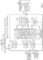
- FIG. 1 is a block diagram explaining an entire configuration of an analysis data creation apparatus 100 according to a first embodiment and the data exchanges between the analysis data creation apparatus 100 and a train or peripheral devices.
- an electric railway vehicle 200 is assumed as an example of the train, and the analysis data creation apparatus 100 collects data relating to an operation status, such as a motor current value, from various devices provided on the electric railway vehicle 200.
- the train exemplified by the electric railway vehicle 200 is composed of one or more vehicles, the number of vehicles constituting one train being arbitrary.
- the data relating to the operation status of the various devices provided on the electric railway vehicle 200 is transmitted to the analysis data creation apparatus 100 by a data transmitter 201 provided on the electric railway vehicle 200.
- the data transmitter 201 transmits the data relating to the operation status of the devices to the analysis data creation apparatus 100 installed on the ground via a regular wireless line 202 while the train is running or stopped.
- the analysis data creation apparatus 100 includes a data storage 101, a data converter 102, a master manager 103, a data interpolator 104, a file creator 105, a creation file storage 106, an extractor 107, a summary creator 108, a data receiver 109, and a data transmitter/receiver 110.
- the data relating to the operation status of the devices transmitted from the electric railway vehicle 200 is received by the data receiver 109. Then, the received data is subjected to a decompression processing and a conversion (such as plaintext processing) and stored in the data storage 101 as operation information data.
- the data may be stored in the data storage 101 at a predetermined cycle, or at an occurrence of an event such as a stop. That is, the data relating to the operation status of the devices generated on the electric railway vehicle 200 may be received every moment and stored in the data storage 101.
- the data relating to the operation status of the devices is compiled for each vehicle, that is, for each vehicle number. Since the data receiver 109 normally receives the data relating to the operation status of the devices from a plurality of vehicles of a plurality of trains, each of the data is stored in the data storage 101 by using vehicle numbers uniquely assigned to the vehicles as identification information.
- FIG. 2 shows an example of the operation information data stored in the data storage 101.
- the operation information data is compiled for each vehicle number.
- the data relating to the operation status of the devices is stored for each vehicle number together with the time when the data was generated.
- the vehicle number is an identifier of the vehicle and is not duplicated.
- a table is prepared for each vehicle number, and the data relating to the operation status of the devices, which is acquired by the analysis data creation apparatus 100, is stored in chronological order starting from the top row of the table. Classifying the tables in accordance with vehicle numbers prevents the data of different vehicles from being compiled in the same table.
- the data relating to the operation status of the devices which is newly acquired by the analysis data creation apparatus 100 is sequentially added to the bottom of the rows in the table and stored.
- the data storage 101 is constituted by a storage device such as a hard disk drive or a nonvolatile memory. If the data storage 101 has sufficient processing capacity, the analysis data creation apparatus 100 can also store the data received by the data receiver 109 as it is in the data storage 101, as the operation information data.
- the data items to be held as the operation information data are assumed to be, for example, a speed, a position, a motor current, a motor voltage, an operation amount, a normal/abnormal flag of the devices, and the like. These data are collected by the devices of the electric railway vehicle 200 in a cycle of one second or a cycle of 100 milliseconds, for example. Therefore, the data amount of the operation information data is enormous.
- the processing capacity of the data storage 101 is not sufficient, then all of the data relating to the operation status of the devices which are collected, for example, in a period of 100 milliseconds, may not be stored.
- the data may be thinned out to partially extract data, for example, in a period of 10 seconds, and stored in the data storage 101 as the operation information data.
- the data items stored and held in the data storage 101 may be limited to a part of the data items, thereby reducing the data amount of the operation information data.
- the data converter 102 converts the data included in the operation information data using a conversion table or a conversion formula. By this data conversion, it is possible to convert the data including character information and the like relating to the operation status of the devices into a numerical value which can be displayed in a graph.
- the numerical value after the data conversion may be additionally written in the operation information data stored in the data storage 101 by the data converter 102, or may be output from the data converter 102 to the file creator 105.
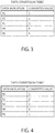
- FIG. 3 is a diagram showing an example of a conversion table for converting the data relating to the operation status of the power running notch of the electric railway vehicle 200
- FIG. 4 is a diagram showing an example of a conversion table for converting the data relating to the operation status of the brake notch of the electric railway vehicle 200.
- P1 is data indicating that the power running notch is operated in the state where the acceleration is the lowest
- P5 is data indicating that the power running notch is operated in the state where the acceleration is the highest.
- P1 is converted into data having a numerical value of 1
- P5 is converted into data having a numerical value of 5.
- B1 is data indicating that the brake notch is operated in the state where the braking is the lowest
- B5 is data indicating that the brake notch is operated in the state where the braking is the highest.
- B1 is converted into data having a numerical value of 1
- B5 is converted into data having a numerical value of 5.
- the power running notch and the brake notch of the electric railway vehicle 200 may be operated not only stepwise as shown in FIG. 3 and FIG. 4 , but also continuously.
- a current value or a voltage value representing the magnitude of the power running notch or the brake notch may be obtained as data relating to the operation state, and the magnitude may be converted into data of numerical value representing a percentage by a conversion formula.
- the data converter 102 can also convert the data including the character information into the data of the numerical value by using a conversion formula instead of the conversion table.
- the master manager 103 manages the conversion table and/or the conversion formula used in the above-described data converter 102. In addition, information from an external system that is not stored in the data storage 101 is acquired and managed.
- a typical example of the information from the external system is a timetable.
- Railways are usually managed by the train timetable.
- the timetable varies between weekdays, weekends, holidays, and so on.
- the time is often plotted on the horizontal axis and the station location on the vertical axis. Then, the graph is expressed by connecting points determined by the departure time and the departure station and points determined by the arrival time and the arrival station.
- the timetable is often managed by another system called an operation management system 500.
- the delay can be evaluated by the difference between the departure time and arrival time of the scheduled timetable and the departure time and arrival time of the actual timetable.
- a train number as an identifier is determined for a line connecting the starting station and the terminal station.
- the operation management of the vehicle is often managed by a vehicle operation system 600 different from the operation management system 500.
- the operation management system 500 holds information about the timetable, and the vehicle operation system 600 holds information about the vehicle allocation in the timetable.
- the master manager 103 acquires and holds the information on the timetable and the information on the vehicle allocation, so that even if the train number, the vehicle number, or the like is missing from the operation information data stored in the data storage 101, it is possible to compensate for these.
- the data interpolator 104 performs an interpolation of the missing data. Specifically, when the train number, the vehicle number, or the like is missing from the operation information data stored in the data storage 101, the data interpolator 104 searches the information on the timetable and the information on the vehicle allocation stored in the master manager 103, and adds the corresponding data to the operation information data.
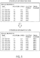
- FIG. 5 is a diagram explaining contents of a data interpolation processing performed by the data interpolator 104.
- the train number is interpolated by searching the information on the timetable and the information on the vehicle allocation stored in the master manager 103.
- the data interpolator 104 searches the information on the vehicle allocation, searches for the train number to which the vehicle number A of the corresponding day is allocated, and as a result of the search, adds the specified train number to the operation information data.
- the file creator 105 creates an analysis file corresponding to a purpose of analysis for each vehicle number based on the operation information data stored in the data storage 101.
- the file creator 105 includes a one-day fixed file creator 105a for creating an analysis file for one day of operation information data, a train number fixed file creator 105b for creating an analysis file for train numbers, an inter-station fixed file creator 105c for creating an analysis file for inter-station of the operation information data, and an event file creator 105d for creating an analysis file for a specific event such as a stop.
- the files created by the file creator 105 are not limited to these files, and various files may be created according to the purpose of the analysis.
- the file creator 105 selects the necessary data items for one day of train numbers, inter-station, and events, and extracts the data items necessary for the analysis from the operation information data.
- the file creator 105 uses the data extraction table stored in the master manager 103.
- FIG. 6 is a diagram showing an example of the data extraction table held by the master manager 103 according to the present embodiment.
- the data extraction table according to the present embodiment all data items that can be acquired from the operation information data stored in the data storage 101 are listed.
- each column corresponds to each data item.
- the types of files for the analysis such as the analysis data 1, the analysis data 2, and the analysis data 3, which are created according to use, are shown.
- "1" is stored in the data item to be extracted when the analysis file is created.
- "0" is stored in a data item which does not need to be extracted when the analysis file is created. That is, in the example of FIG. 6 , " 1 " is stored as an information indicating that the data item is to be extracted, and "0" is stored as an information indicating that the data item is not to be extracted.
- the data items 1 to 10 are data items to be extracted.
- "1" is stored for each of the data items 1 to 5 and 8 to 10
- "0" is stored for each of the data items 6 and 7. Therefore, it is shown that the data of the data items 1 to 5 and the items 8 to 10 are extracted, but the data of the data item 6 and the data item 7 are not extracted.
- "1" is stored for each of the data items 1 to 7, and "0" is stored for each of the data items 8 to 10. Therefore, it is shown that the data of the data items 1 to 7 are extracted, but the data of the data items 8 to 10 are not extracted.
- the one-day fixed file creator 105a of the file creator 105 selects data to be extracted from the operation information data stored in the data storage 101 on the basis of an information relating to data extraction stored in the row of the analysis data 1 of the data extraction table.
- the data extraction table By using the data extraction table in this manner, it is possible to efficiently extract the data item necessary for creating the analysis file.
- the analyst desires to add a data item to the analysis file once he has looked at the analysis file and performed a detailed analysis, the data item can be added to the analysis file by simply changing the corresponding data item in the data extraction table from 0 to 1.
- the data item can be prevented from being included in the analysis file by simply changing the data item in the data extraction table from 1 to 0.
- the timing when the file creator 105 creates the analysis file is arbitrary.
- the one-day fixed file creator 105a may create the one-day fixed file by using the fact that all the operation information data of the day is stored in the data storage 101 as a trigger.
- the train number fixed file may be created by the train number fixed file creator 105b by using the fact that the train of the corresponding train number has ended its run and the operation information data including the end time has been stored in the data storage 101 as a trigger.
- the inter-station fixed file may be created by the inter-station fixed file creator 105c by using the fact that all the operation information data of the day is stored in the data storage 101 as a trigger.
- the event to be detected may be defined in the master manager 103, and the event file may be created by the event file creator 105d by using the occurrence of the event corresponding to the definition in the train as a trigger.
- the event file creator 105d creates the event file by extracting the operation information data for a 30-second period before and after the event by using data including the vehicle number of the vehicle constituting the train in which the event occurred and including the time of occurrence.
- These analysis files created by the file creator 105 are stored in the creation file storage 106.
- the data format of the analysis file is arbitrary, in this embodiment, for example, the file is created in a CSV format.
- the file creator 105 may automatically recreate the analysis file based on the updated data extraction table. For example, when the analyst changes the value of some data items in the data extraction table from 0 to 1 by using a general-purpose computer 300, the file creator 105 may recreate the analysis file again based on the updated data extraction table.
- the data converter 102 may automatically convert the operation information data stored in the data storage 101 to the numerical value based on the updated conversion table and the conversion formula. Thereafter, the file creator 105 may automatically create the analysis file based on the operation information data including the newly converted numerical value.
- FIG. 7 is a diagram showing an example of a file storage configuration of the creation file storage 106 according to the present embodiment.
- a hierarchically lower-level folder is created with the vehicle number as its higher-level folder.
- a "one-day” lower-level folder, a "train number” lower-level folder, an "inter-station” lower-level folder, and an "event” lower-level folder are created.
- the file name of the analysis file is named so that it can be distinguished from each other, and therefore, for example, the one-day fixed file is named so that the file name includes a date.
- the train number fixed file is named so that the file name includes the train number and the data start date or data end date of the train.
- the train number fixed file for each train number is further divided for each station, and the file name is named so as to include information on the departure station and the arrival station.
- the event file is named so that the file name includes a unique ID for identifying the event and the date and time of occurrence.
- the analysis file stored in the creation file storage 106 may be automatically deleted after a predetermined period of time has elapsed, for example, 1 years after the creation.
- the creation file storage 106 may automatically delete the analysis file by itself, or the file creator 105 may periodically search the creation date of the analysis file stored in the creation file storage 106, and delete the analysis file if it is detected after a predetermined period of time has elapsed. This makes it possible to reduce the storage occupancy of the creation file storage 106.
- the extractor 107 When a download request for the analysis file is received from the external general-purpose computer 300 connected via the data transmitter/receiver 110, the extractor 107 extracts the analysis file that matches the condition from the creation file storage 106 and transmits the extracted file as an analysis output file 400 to the general-purpose computer 300 which is the download request source. That is, since the analyst designates the analysis file required for analysis or designates the condition of a necessary file via the general-purpose computer 300, the extractor 107 acquires the analysis file matching the designated condition from the creation file storage 106 and transmits it to the general-purpose computer 300 as the analysis output file 400 via the data transmitter/receiver 110.
- the summary creator 108 creates a summary file, which allows the analyst to grasp the outline of the analysis file, based on the analysis file stored in the creation file storage 106. Then, the summary creator 108 stores the created summary file in the creation file storage 106.
- FIG. 8 is a diagram illustrating an example of the data structure of the summary file created by the summary creator 108 based on the one-day fixed file
- FIG. 9 is a diagram illustrating an example of the data structure of the summary file created by the summary creator 108 based on the train number fixed file.
- the summary files shown in FIG. 8 and FIG. 9 both show a summary of the operation.
- the summary of the operation is a calculation of a statistic at the time of operation in units of each file.
- the travel distance, the maximum speed, and the consumed energy are statistics to be calculated for each vehicle number.
- the date on which the statistic was calculated is held as an additional information.
- the travel distance, the maximum speed, and the consumed energy are statistics to be calculated. Further, the train number and the start date of the train of the train number are held as an additional information.
- the items for which the summary creator 108 calculates the statistics are not limited to these items, and they can be arbitrarily set from the outside.
- the analyst can operate the general-purpose computer 300 to specify a statistic to be calculated by the summary creator 108.
- the analysis file used to create the summary file is not limited to the one-day fixed file and the train number fixed file, and the summary file may be created using other analysis files.
- the summary creator 108 may also calculate the number of pieces of data satisfying a predetermined abnormal condition as a statistic from the analysis file, and add the calculation result to the summary file. For example, a case where the maximum speed exceeds a predetermined value may be defined as an abnormal condition, and the number of corresponding pieces of data may be calculated as a statistic.
- the definition of the abnormal condition may be held by the summary creator 108 or may be held by the master manager 103 and acquired by the summary creator 108.
- the summary creator 108 may acquire an information about the scheduled timetable held in the master manager 103, compare the departure time and arrival time of the scheduled timetable with the actual departure time and arrival time of the operation, calculate the delay time as a statistic, and add it to the summary file.
- the actual departure time and arrival time of the operation may be obtained from the analysis file stored in the creation file storage 106, from the operation information data stored in the data storage 101, or from the actual timetable held by the master manager 103.
- the summary creator 108 calculates a statistic based on the data stored in the analysis file and adds the calculation result on the bottom line of the summary file. Therefore, the summary creator 108 performs a process of reading out the existing summary file from the creation file storage 106, adding the calculation result thereto, and storing it again in the creation file storage 106. If the statistic can be calculated by the summary creator 108 based on a data item that can be calculated even before the completion of the creation of the one analysis files, the summary creator 108 may read the analysis file and create the summary file at the timing when the statistic can be calculated for the data item.
- FIG. 10 is a flowchart showing the contents of the summary creation processing executed by the summary creator 108 according to the present embodiment.
- the summary creator 108 determines whether or not a timing for creating a summary file has been detected (step S10). As described above, the timing at which the summary file is created includes the timing at which the analysis file is created, the timing at which the statistic can be calculated, and so on. If the timing for creating the summary file is not detected (step S10: No), the summary creation processing is terminated.
- step S10 when the timing for creating the summary file is detected (step S10: Yes), the summary creator 108 acquires an analysis file necessary for calculating a statistic, from the creation file storage 106 (step S12). Then, the data item necessary for calculating the statistic is read out from the analysis file, and the required statistic is calculated (step S14).
- the summary creator 108 acquires, from the creation file storage 106, the existing summary file in which previously created statistics are stored (step S16). Subsequently, the summary creator 108 adds the calculation result of the statistic in step S14 to the existing summary file and stores this new summary file in the creation file storage 106 (step S18). Then, the summary creation processing is ended.
- the summary file stored in the creation file storage 106 can be obtained by the general-purpose computer 300 as the analysis output file 400 by designation by the analyst who operates the general-purpose computer 300. That is, when a condition is specified from the general-purpose computer 300, the extractor 107 extracts a summary file that matches the specified condition from the creation file storage 106 and outputs it to the general-purpose computer 300 as the analysis output file 400.
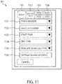
- FIG. 11 is a diagram showing an example of a display screen W1 displayed on a screen provided to the general-purpose computer 300.
- the display screen W1 is displayed by the Web browser of the general-purpose computer 300.
- the drawing control for displaying the display screen W1 on the Web browser of the general-purpose computer 300 is executed by the extractor 107 of the analysis data creation apparatus 100.
- an event tab TB1 a one-day fixed tab TB2, a train number fixed tab TB3, and an inter-station fixed tab TB4
- the analyst selects one of the tabs as the data he wants to analyze, considering which analysis file is the most suitable.
- the display screen W1 includes a train number designation field FD1, a vehicle number designation field FD2, a start time designation field FD3, an end time designation field FD4, a template download type designation field FD5, and a destination mail address designation field FD6. These specified fields can also be changed when one of the four tabs is selected.
- the train number designation field FD1 is a field for inputting a train number which the analyst wishes to acquire for analysis.
- the vehicle number designation field TD2 is a field for inputting a vehicle number which the analyst wishes to acquire for analysis.
- the start time designation field FD3 is a field for inputting a start time of the operation information data which the analyst wishes to acquire for analysis.
- the end time designation field FD4 is a field for inputting an end time of the operation information data which the analyst wishes to acquire for analysis.
- the template download type designation field FD5 is a field for designating a type of the template to be downloaded by the analyst.
- the destination mail address designation field FD6 is a field for designating a destination address in the case of transmitting the downloaded analysis file by e-mail.
- the analyst inputs a condition for obtaining optimum data for the analysis on the display screen W1 and acquires a target analysis file. That is, based on the input of the display screen W1, the general-purpose computer 300 transmits a download request for extracting at least one of the vehicle number of the vehicles constituting the train, the train number of the train, the start time of the operation information data, and the end time of the operation information data, to the extractor 107 of the analysis data creation apparatus 100. In response to the download request, the extractor 107 retrieves and extracts the analysis file matching the condition from the creation file storage 106 and transmits the file to the general-purpose computer 300 as the request source.
- the analyst can connect the general-purpose computer 300 to the data transmitter/receiver 110 of the analysis data creation apparatus 100 and easily obtain the analysis output file 400 required for analysis. That is, the file creator 105 has created the analysis file organized to include predetermined data items such as the one-day fixed file, the train number fixed file, the inter-station fixed file, and the event file, and has stored the created file in the creation file storage 106, and therefore the analyst can easily acquire the necessary analysis file in a short time. Therefore, the analyst does not have to extract the necessary data items from the enormous amount of the operation information data and to create the analysis file each time. Therefore, the very short time of downloading from the creation file storage 106 the analysis file that has already been created is the time required for (2) the data pre-processing.
- the analyst can grasp the outline of the data stored in the analysis file before performing detailed data analysis in the analysis file by acquiring the summary file as the analysis output file 400 in the general-purpose computer 300.
- the analyst can analyze the operation information data based on the analysis file stored in the creation file storage 106 from which the necessary data items have been extracted in advance, instead of directly acquiring the operation information data stored in the data storage 101 and extracting or arranging the data items necessary for the analysis. Therefore, it is possible to greatly shorten the work time such as (1) the data acquisition and (2) the data pre-processing, which has conventionally been very time consuming.
- the data is separated by a predetermined time such as 10 minutes or 1 hour, there is a possibility that the data is not separated into meaningful data because the train is not in operation or is moving between stations.
- a predetermined time such as 10 minutes or 1 hour
- the data becomes meaningful data which is easy for the analyst to analyze.
- the analysis file created with this meaningful data is created in advance and stored in the creation file storage 106, and the analyst uses this analysis file, so that the time conventionally required for (2) data pre-processing for the analyst can be greatly reduced.
- the analyst work regarding (1) the data acquisition and (2) the data pre-processing of the analyst can be reduced, but when a large amount of data is to be analyzed, the analyst must download and acquire a large number of the analysis files from the creation file storage 106. In this case, the time required to create the analysis files can be reduced but the time required to download the analysis files is expected to be considerably long.
- the operation information data of the train is collected under various conditions.
- the operation information data includes a mixture of data in which a large delay occurs and data in which no delay occurs.
- the energy consumption is evaluated, if a delay occurs, the energy consumption tends to be larger than that in a case where no delay occurs, because the operation information data that has been operated at a speed faster than that of the normal timetable in order to recover the delay is included. It may not make much sense to compare the operation information data under very different conditions.
- the contents of the summary files created by the summary creator 108 of the analysis data creation apparatus 100 according to the first embodiment and stored in the creation file storage 106, are visually depicted on the general-purpose computer 300 by using a Web browser, so that the analyst can efficiently select the analysis file. That is, the extractor 107 of the analysis data creation apparatus 100 provides the analyst with the Web browser for requesting a download and specifying an extraction condition.
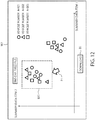
- FIG. 12 is a diagram showing an example of the display screen W2 displayed on the screen of the general-purpose computer 300 connected to the analysis data creation apparatus 100 according to the present embodiment.
- the statistic of the summary file related to the one-day fixed file is shown.
- the statistic of the vehicles having three different vehicle numbers is displayed.
- the train number fixed file is displayed
- the statistic of the different train numbers may be displayed
- the inter-station fixed file is displayed, the statistic of the different inter-station may be displayed.
- the summary data items 1 and 2 in the summary file relating to the one-day fixed file are displayed in the form of a scatter diagram on a horizontal axis and a vertical axis, respectively.
- the horizontal axis represents the travel distance in the summary file of FIG. 8
- the vertical axis represents the maximum speed in the summary file of FIG. 8 .
- the triangle, circle, and square represent 1 one-day fixed file for each vehicle number.
- the display format is not limited to the scatter diagram, and other display formats, such as histograms, may be used.
- the summary data items on the vertical axis or the horizontal axis are arbitrary, and may be data items held by the summary file, such as the travel distance, the maximum speed, and the consumed energy, or may be a statistic that can be calculated anew from the data items held by the summary file.
- the vertical axis or the horizontal axis may represent a statistic that can be calculated from timetable information managed by the operation management system 500 or vehicle allocation information managed by the vehicle operation system 600.
- the analyst can arbitrarily set what data items to be set on the vertical axis and the horizontal axis.
- the analyst selects the analysis file to be downloaded.
- the analyst operates a pointing device to move a pointer P1 on the display screen W2 and surrounds the analysis file to be downloaded with the frame box BX1.
- the selected analysis files that is, the one-day fixed files are downloaded to the general-purpose computer 300.
- 11 one-day fixed files are downloaded.
- the analyst can visually recognize the data such as the statistic of the summary file on the display screen W2 displayed on the general-purpose computer 300, and can easily grasp the contents of the summary file.
- the download time can be shortened and the efficiency of the analysis work can be improved by omitting unnecessary data.
Landscapes
- Engineering & Computer Science (AREA)
- Mechanical Engineering (AREA)
- Health & Medical Sciences (AREA)
- Biomedical Technology (AREA)
- General Health & Medical Sciences (AREA)
- Train Traffic Observation, Control, And Security (AREA)
- Management, Administration, Business Operations System, And Electronic Commerce (AREA)
Abstract
Description
- An embodiment of the present invention relates to an analysis data creation apparatus.
- By collecting and analyzing data on an operation status of a device provided in an operating train, an introduction of an apparatus that detects and predicts abnormalities in the device provided in the train is being promoted. In such apparatus, the manner of analyzing the collected data is important.
- When analyzing data, (1) a data acquisition, (2) a data pre-processing, and (3) a data analysis is often performed in this order. With regard to (1) the data acquisition, a large amount of data can be acquired using various sensors provided in the device in the train. Here, the data sensed by the device in the train is referred to as an operation information data. In many cases, the sensed data is stored as it is, or data unnecessary for the analysis is included, and therefore a preparation work is required before data analysis. This is referred to as (2) the data pre-processing.
- (2) The pre-processing of the data is often performed manually by an analyst using a local general-purpose computer having acquired the data. That is, the analyst acquires the operation information data by the local general-purpose computer, extracts a data item necessary for the data analysis, converts the data, and performs (3) the data analysis work. Among these tasks, the analyst wants to spend most of his time on (3) the data analysis, but in fact, he may also spend a lot of time on (1) the data acquisition and on (2) the data pre-processing.
-
- Patent Document 1: Japanese Patent Application Laid-Open No.
2016 - 12240 - Patent Document 2: Japanese Patent Application Laid-Open No.
2016 - 29516 - Patent Document 3: Japanese Patent Application Laid-Open No.
2010 - 231708 - An analysis data creation apparatus, which enables an analyst to easily acquire an analysis file used for a data analysis work from operation information data, is provided.
- An analysis data creation apparatus, according to the present embodiment, includes:
- a data storage in which data relating to an operation status of a device provided in an operating train is stored as operation information data;
- a master manager configured to hold a data extraction table defining data item to be extracted when an analyst extracts the data item required for analysis from the operation information data stored in the data storage and creates an analysis file;
- a file creator configured to create the analysis file by extracting the data item from the operation information data based on the data extraction table held in the master manager; and
- a creation file storage in which the analysis file created by the file creator is stored.
-
-
FIG. 1 is a block diagram explaining an entire configuration of an analysis data creation apparatus according to a first embodiment and the data exchanges with trains and peripheral devices. -
FIG. 2 is a diagram showing an example of a configuration of operation information data stored in a data storage of the analysis data creation apparatus according to the first embodiment. -
FIG. 3 illustrates an example of a conversion table for converting data regarding an operation status of a power running notch into a numerical value. -
FIG. 4 illustrates an example of a conversion table for converting data regarding an operation status of a brake notch into a numerical value. -
FIG. 5 is a diagram explaining contents of a data interpolation processing performed by a data interpolator of the analysis data creation apparatus according to the first embodiment. -
FIG. 6 is a diagram showing an example of a data extraction table held by a master manager of the analysis data creation apparatus according to the first embodiment. -
FIG. 7 is a diagram showing an example of a file storage configuration of a creation file storage of the analysis data creation apparatus according to the first embodiment. -
FIG. 8 is a diagram for explaining an example of a data structure of a summary file created based on a one-day fixed file by a summary creator of the analysis data creation apparatus according to the first embodiment. -
FIG. 9 is a diagram for explaining an example of a data structure of a summary file created based on a train number fixed file by the summary creator of the analysis data creation apparatus according to the first embodiment. -
FIG. 10 is a flowchart showing contents of a summary creation processing executed by the summary creator of the analysis data creation apparatus according to the first embodiment. -
FIG. 11 is a diagram showing an example of a display screen displayed on a screen of a general-purpose computer connected to the analysis data creation apparatus according to the first embodiment. -
FIG. 12 is a diagram showing an example of a display screen displayed on a screen of a general-purpose computer connected to an analysis data creation apparatus according to a second embodiment. - Hereinafter, an analysis data creation apparatus according to several embodiments will be described with reference to the drawings. In the following description, components having substantially the same functions and configurations are denoted by the same reference numerals, and redundant descriptions will be made only when necessary.
-
FIG. 1 is a block diagram explaining an entire configuration of an analysisdata creation apparatus 100 according to a first embodiment and the data exchanges between the analysisdata creation apparatus 100 and a train or peripheral devices. - As shown in
FIG. 1 , in the present embodiment, anelectric railway vehicle 200 is assumed as an example of the train, and the analysisdata creation apparatus 100 collects data relating to an operation status, such as a motor current value, from various devices provided on theelectric railway vehicle 200. Here, the train exemplified by theelectric railway vehicle 200 is composed of one or more vehicles, the number of vehicles constituting one train being arbitrary. - In this embodiment, the data relating to the operation status of the various devices provided on the
electric railway vehicle 200 is transmitted to the analysisdata creation apparatus 100 by adata transmitter 201 provided on theelectric railway vehicle 200. For example, thedata transmitter 201 transmits the data relating to the operation status of the devices to the analysisdata creation apparatus 100 installed on the ground via a regularwireless line 202 while the train is running or stopped. - In this embodiment, the analysis
data creation apparatus 100 includes adata storage 101, adata converter 102, amaster manager 103, adata interpolator 104, afile creator 105, acreation file storage 106, anextractor 107, asummary creator 108, adata receiver 109, and a data transmitter/receiver 110. - The data relating to the operation status of the devices transmitted from the
electric railway vehicle 200 is received by thedata receiver 109. Then, the received data is subjected to a decompression processing and a conversion (such as plaintext processing) and stored in thedata storage 101 as operation information data. The data may be stored in thedata storage 101 at a predetermined cycle, or at an occurrence of an event such as a stop. That is, the data relating to the operation status of the devices generated on theelectric railway vehicle 200 may be received every moment and stored in thedata storage 101. When the data is stored in thedata storage 101, the data relating to the operation status of the devices is compiled for each vehicle, that is, for each vehicle number. Since thedata receiver 109 normally receives the data relating to the operation status of the devices from a plurality of vehicles of a plurality of trains, each of the data is stored in thedata storage 101 by using vehicle numbers uniquely assigned to the vehicles as identification information. -
FIG. 2 shows an example of the operation information data stored in thedata storage 101. As shown inFIG. 2 , the operation information data is compiled for each vehicle number. The data relating to the operation status of the devices is stored for each vehicle number together with the time when the data was generated. The vehicle number is an identifier of the vehicle and is not duplicated. - In the present embodiment, a table is prepared for each vehicle number, and the data relating to the operation status of the devices, which is acquired by the analysis
data creation apparatus 100, is stored in chronological order starting from the top row of the table. Classifying the tables in accordance with vehicle numbers prevents the data of different vehicles from being compiled in the same table. The data relating to the operation status of the devices which is newly acquired by the analysisdata creation apparatus 100 is sequentially added to the bottom of the rows in the table and stored. - The
data storage 101 is constituted by a storage device such as a hard disk drive or a nonvolatile memory. If thedata storage 101 has sufficient processing capacity, the analysisdata creation apparatus 100 can also store the data received by thedata receiver 109 as it is in thedata storage 101, as the operation information data. The data items to be held as the operation information data are assumed to be, for example, a speed, a position, a motor current, a motor voltage, an operation amount, a normal/abnormal flag of the devices, and the like. These data are collected by the devices of theelectric railway vehicle 200 in a cycle of one second or a cycle of 100 milliseconds, for example. Therefore, the data amount of the operation information data is enormous. - If the processing capacity of the
data storage 101 is not sufficient, then all of the data relating to the operation status of the devices which are collected, for example, in a period of 100 milliseconds, may not be stored. The data may be thinned out to partially extract data, for example, in a period of 10 seconds, and stored in thedata storage 101 as the operation information data. Further, the data items stored and held in thedata storage 101 may be limited to a part of the data items, thereby reducing the data amount of the operation information data. - As shown in
FIG. 1 again, thedata converter 102 converts the data included in the operation information data using a conversion table or a conversion formula. By this data conversion, it is possible to convert the data including character information and the like relating to the operation status of the devices into a numerical value which can be displayed in a graph. The numerical value after the data conversion may be additionally written in the operation information data stored in thedata storage 101 by thedata converter 102, or may be output from thedata converter 102 to thefile creator 105. -
FIG. 3 is a diagram showing an example of a conversion table for converting the data relating to the operation status of the power running notch of theelectric railway vehicle 200, andFIG. 4 is a diagram showing an example of a conversion table for converting the data relating to the operation status of the brake notch of theelectric railway vehicle 200. - In
FIG. 3 , P1 is data indicating that the power running notch is operated in the state where the acceleration is the lowest, and P5 is data indicating that the power running notch is operated in the state where the acceleration is the highest. In the data conversion table ofFIG. 3 , P1 is converted into data having a numerical value of 1, and P5 is converted into data having a numerical value of 5. - In
FIG. 4 , B1 is data indicating that the brake notch is operated in the state where the braking is the lowest, and B5 is data indicating that the brake notch is operated in the state where the braking is the highest. In the data conversion table ofFIG. 4 , B1 is converted into data having a numerical value of 1, and B5 is converted into data having a numerical value of 5. - The power running notch and the brake notch of the
electric railway vehicle 200 may be operated not only stepwise as shown inFIG. 3 and FIG. 4 , but also continuously. In such a case, for example, a current value or a voltage value representing the magnitude of the power running notch or the brake notch may be obtained as data relating to the operation state, and the magnitude may be converted into data of numerical value representing a percentage by a conversion formula. Thedata converter 102 can also convert the data including the character information into the data of the numerical value by using a conversion formula instead of the conversion table. - As shown in
FIG. 1 again, themaster manager 103 manages the conversion table and/or the conversion formula used in the above-describeddata converter 102. In addition, information from an external system that is not stored in thedata storage 101 is acquired and managed. - A typical example of the information from the external system is a timetable. Railways are usually managed by the train timetable. The timetable varies between weekdays, weekends, holidays, and so on. In order to make a graph based on the timetable, the time is often plotted on the horizontal axis and the station location on the vertical axis. Then, the graph is expressed by connecting points determined by the departure time and the departure station and points determined by the arrival time and the arrival station.
- In the railway business, the timetable is often managed by another system called an
operation management system 500. There are two types of timetable: the scheduled timetable which shows the scheduled departure time and arrival time, and the actual timetable which shows the actual departure time and arrival time. The delay can be evaluated by the difference between the departure time and arrival time of the scheduled timetable and the departure time and arrival time of the actual timetable. - Generally, a train number as an identifier is determined for a line connecting the starting station and the terminal station. In the operation of railways, it is decided which vehicles are allocated to each train number. This is called a vehicle allocation. The operation management of the vehicle is often managed by a
vehicle operation system 600 different from theoperation management system 500. - The
operation management system 500 holds information about the timetable, and thevehicle operation system 600 holds information about the vehicle allocation in the timetable. Themaster manager 103 acquires and holds the information on the timetable and the information on the vehicle allocation, so that even if the train number, the vehicle number, or the like is missing from the operation information data stored in thedata storage 101, it is possible to compensate for these. - The
data interpolator 104 performs an interpolation of the missing data. Specifically, when the train number, the vehicle number, or the like is missing from the operation information data stored in thedata storage 101, the data interpolator 104 searches the information on the timetable and the information on the vehicle allocation stored in themaster manager 103, and adds the corresponding data to the operation information data. -
FIG. 5 is a diagram explaining contents of a data interpolation processing performed by thedata interpolator 104. As shown inFIG. 5 , for example, when the train number information is missing from the operation information data stored in thedata storage 101, the train number is interpolated by searching the information on the timetable and the information on the vehicle allocation stored in themaster manager 103. For example, the data interpolator 104 searches the information on the vehicle allocation, searches for the train number to which the vehicle number A of the corresponding day is allocated, and as a result of the search, adds the specified train number to the operation information data. - As shown in
FIG. 1 again, thefile creator 105 creates an analysis file corresponding to a purpose of analysis for each vehicle number based on the operation information data stored in thedata storage 101. In this embodiment, thefile creator 105 includes a one-day fixedfile creator 105a for creating an analysis file for one day of operation information data, a train number fixedfile creator 105b for creating an analysis file for train numbers, an inter-station fixedfile creator 105c for creating an analysis file for inter-station of the operation information data, and anevent file creator 105d for creating an analysis file for a specific event such as a stop. Of course, the files created by thefile creator 105 are not limited to these files, and various files may be created according to the purpose of the analysis. - Here, when the purpose of the analysis is, for example, to analyze running and energy or to analyze the surroundings of the motor, in many cases, the data items required for the analysis are not all items of the operation information data. Therefore, the
file creator 105 selects the necessary data items for one day of train numbers, inter-station, and events, and extracts the data items necessary for the analysis from the operation information data. Here, in order to select the necessary data items, thefile creator 105 uses the data extraction table stored in themaster manager 103. -
FIG. 6 is a diagram showing an example of the data extraction table held by themaster manager 103 according to the present embodiment. As shown inFIG. 6 , in the data extraction table according to the present embodiment, all data items that can be acquired from the operation information data stored in thedata storage 101 are listed. In the example ofFIG. 6 , each column corresponds to each data item. In each row, the types of files for the analysis, such as theanalysis data 1, theanalysis data 2, and theanalysis data 3, which are created according to use, are shown. "1" is stored in the data item to be extracted when the analysis file is created. On the other hand, "0" is stored in a data item which does not need to be extracted when the analysis file is created. That is, in the example ofFIG. 6 , "1 " is stored as an information indicating that the data item is to be extracted, and "0" is stored as an information indicating that the data item is not to be extracted. - Referring to the row of the
analysis data 1 as an example, "1" is stored for each of thedata items 1 to 10, and therefore, it is shown that thedata items 1 to 10 are data items to be extracted. In theanalysis data 2, "1" is stored for each of thedata items 1 to 5 and 8 to 10, and "0" is stored for each of thedata items data items 1 to 5 and theitems 8 to 10 are extracted, but the data of thedata item 6 and thedata item 7 are not extracted. In theanalysis data 3, "1" is stored for each of thedata items 1 to 7, and "0" is stored for each of thedata items 8 to 10. Therefore, it is shown that the data of thedata items 1 to 7 are extracted, but the data of thedata items 8 to 10 are not extracted. - For example, when the
analysis data 1 corresponds to a one-day fixed file, the one-day fixedfile creator 105a of thefile creator 105 selects data to be extracted from the operation information data stored in thedata storage 101 on the basis of an information relating to data extraction stored in the row of theanalysis data 1 of the data extraction table. By using the data extraction table in this manner, it is possible to efficiently extract the data item necessary for creating the analysis file. In addition, even if the analyst desires to add a data item to the analysis file once he has looked at the analysis file and performed a detailed analysis, the data item can be added to the analysis file by simply changing the corresponding data item in the data extraction table from 0 to 1. On the other hand, even if the analyst desires to delete a data item from the analysis file after he has looked at the analysis file and performed a detailed analysis, the data item can be prevented from being included in the analysis file by simply changing the data item in the data extraction table from 1 to 0. - The timing when the
file creator 105 creates the analysis file is arbitrary. For example, the one-day fixedfile creator 105a may create the one-day fixed file by using the fact that all the operation information data of the day is stored in thedata storage 101 as a trigger. The train number fixed file may be created by the train number fixedfile creator 105b by using the fact that the train of the corresponding train number has ended its run and the operation information data including the end time has been stored in thedata storage 101 as a trigger. The inter-station fixed file may be created by the inter-station fixedfile creator 105c by using the fact that all the operation information data of the day is stored in thedata storage 101 as a trigger. Regarding the event file, the event to be detected may be defined in themaster manager 103, and the event file may be created by theevent file creator 105d by using the occurrence of the event corresponding to the definition in the train as a trigger. For example, theevent file creator 105d creates the event file by extracting the operation information data for a 30-second period before and after the event by using data including the vehicle number of the vehicle constituting the train in which the event occurred and including the time of occurrence. These analysis files created by thefile creator 105 are stored in thecreation file storage 106. Although the data format of the analysis file is arbitrary, in this embodiment, for example, the file is created in a CSV format. - Also, when the data extraction table held by the
master manager 103 is updated, thefile creator 105 may automatically recreate the analysis file based on the updated data extraction table. For example, when the analyst changes the value of some data items in the data extraction table from 0 to 1 by using a general-purpose computer 300, thefile creator 105 may recreate the analysis file again based on the updated data extraction table. - Further, when at least one of the conversion table and the conversion formula held in the
master manager 103 is updated, thedata converter 102 may automatically convert the operation information data stored in thedata storage 101 to the numerical value based on the updated conversion table and the conversion formula. Thereafter, thefile creator 105 may automatically create the analysis file based on the operation information data including the newly converted numerical value. - As shown in
FIG. 1 again, thecreation file storage 106 stores and holds the analysis file created by thefile creator 105.FIG. 7 is a diagram showing an example of a file storage configuration of thecreation file storage 106 according to the present embodiment. In the example ofFIG. 7 , a hierarchically lower-level folder is created with the vehicle number as its higher-level folder. In this case, a "one-day" lower-level folder, a "train number" lower-level folder, an "inter-station" lower-level folder, and an "event" lower-level folder are created. - The file name of the analysis file is named so that it can be distinguished from each other, and therefore, for example, the one-day fixed file is named so that the file name includes a date. The train number fixed file is named so that the file name includes the train number and the data start date or data end date of the train. In the inter-station fixed file, the train number fixed file for each train number is further divided for each station, and the file name is named so as to include information on the departure station and the arrival station. The event file is named so that the file name includes a unique ID for identifying the event and the date and time of occurrence.
- The analysis file stored in the
creation file storage 106 may be automatically deleted after a predetermined period of time has elapsed, for example, 1 years after the creation. Thecreation file storage 106 may automatically delete the analysis file by itself, or thefile creator 105 may periodically search the creation date of the analysis file stored in thecreation file storage 106, and delete the analysis file if it is detected after a predetermined period of time has elapsed. This makes it possible to reduce the storage occupancy of thecreation file storage 106. - When a download request for the analysis file is received from the external general-
purpose computer 300 connected via the data transmitter/receiver 110, theextractor 107 extracts the analysis file that matches the condition from thecreation file storage 106 and transmits the extracted file as ananalysis output file 400 to the general-purpose computer 300 which is the download request source. That is, since the analyst designates the analysis file required for analysis or designates the condition of a necessary file via the general-purpose computer 300, theextractor 107 acquires the analysis file matching the designated condition from thecreation file storage 106 and transmits it to the general-purpose computer 300 as theanalysis output file 400 via the data transmitter/receiver 110. - The
summary creator 108 creates a summary file, which allows the analyst to grasp the outline of the analysis file, based on the analysis file stored in thecreation file storage 106. Then, thesummary creator 108 stores the created summary file in thecreation file storage 106. -
FIG. 8 is a diagram illustrating an example of the data structure of the summary file created by thesummary creator 108 based on the one-day fixed file, andFIG. 9 is a diagram illustrating an example of the data structure of the summary file created by thesummary creator 108 based on the train number fixed file. The summary files shown inFIG. 8 and FIG. 9 both show a summary of the operation. Here, the summary of the operation is a calculation of a statistic at the time of operation in units of each file. - In the example of
FIG. 8 , the travel distance, the maximum speed, and the consumed energy are statistics to be calculated for each vehicle number. The date on which the statistic was calculated is held as an additional information. In the example ofFIG. 9 , for each train number, the travel distance, the maximum speed, and the consumed energy are statistics to be calculated. Further, the train number and the start date of the train of the train number are held as an additional information. However, the items for which thesummary creator 108 calculates the statistics are not limited to these items, and they can be arbitrarily set from the outside. For example, the analyst can operate the general-purpose computer 300 to specify a statistic to be calculated by thesummary creator 108. The analysis file used to create the summary file is not limited to the one-day fixed file and the train number fixed file, and the summary file may be created using other analysis files. - The
summary creator 108 may also calculate the number of pieces of data satisfying a predetermined abnormal condition as a statistic from the analysis file, and add the calculation result to the summary file. For example, a case where the maximum speed exceeds a predetermined value may be defined as an abnormal condition, and the number of corresponding pieces of data may be calculated as a statistic. The definition of the abnormal condition may be held by thesummary creator 108 or may be held by themaster manager 103 and acquired by thesummary creator 108. - Further, the
summary creator 108 may acquire an information about the scheduled timetable held in themaster manager 103, compare the departure time and arrival time of the scheduled timetable with the actual departure time and arrival time of the operation, calculate the delay time as a statistic, and add it to the summary file. The actual departure time and arrival time of the operation may be obtained from the analysis file stored in thecreation file storage 106, from the operation information data stored in thedata storage 101, or from the actual timetable held by themaster manager 103. - When one analysis file is created, the
summary creator 108 calculates a statistic based on the data stored in the analysis file and adds the calculation result on the bottom line of the summary file. Therefore, thesummary creator 108 performs a process of reading out the existing summary file from thecreation file storage 106, adding the calculation result thereto, and storing it again in thecreation file storage 106. If the statistic can be calculated by thesummary creator 108 based on a data item that can be calculated even before the completion of the creation of the one analysis files, thesummary creator 108 may read the analysis file and create the summary file at the timing when the statistic can be calculated for the data item. -
FIG. 10 is a flowchart showing the contents of the summary creation processing executed by thesummary creator 108 according to the present embodiment. As shown inFIG. 10 , thesummary creator 108 determines whether or not a timing for creating a summary file has been detected (step S10). As described above, the timing at which the summary file is created includes the timing at which the analysis file is created, the timing at which the statistic can be calculated, and so on. If the timing for creating the summary file is not detected (step S10: No), the summary creation processing is terminated. - On the other hand, when the timing for creating the summary file is detected (step S10: Yes), the
summary creator 108 acquires an analysis file necessary for calculating a statistic, from the creation file storage 106 (step S12). Then, the data item necessary for calculating the statistic is read out from the analysis file, and the required statistic is calculated (step S14). - Next, the
summary creator 108 acquires, from thecreation file storage 106, the existing summary file in which previously created statistics are stored (step S16). Subsequently, thesummary creator 108 adds the calculation result of the statistic in step S14 to the existing summary file and stores this new summary file in the creation file storage 106 (step S18). Then, the summary creation processing is ended. - The summary file stored in the
creation file storage 106 can be obtained by the general-purpose computer 300 as theanalysis output file 400 by designation by the analyst who operates the general-purpose computer 300. That is, when a condition is specified from the general-purpose computer 300, theextractor 107 extracts a summary file that matches the specified condition from thecreation file storage 106 and outputs it to the general-purpose computer 300 as theanalysis output file 400. -
FIG. 11 is a diagram showing an example of a display screen W1 displayed on a screen provided to the general-purpose computer 300. In this embodiment, the display screen W1 is displayed by the Web browser of the general-purpose computer 300. The drawing control for displaying the display screen W1 on the Web browser of the general-purpose computer 300 is executed by theextractor 107 of the analysisdata creation apparatus 100. - As shown in
FIG. 11 , four tabs, namely, an event tab TB1, a one-day fixed tab TB2, a train number fixed tab TB3, and an inter-station fixed tab TB4, are displayed on the display screen W1. The analyst selects one of the tabs as the data he wants to analyze, considering which analysis file is the most suitable. - The display screen W1 includes a train number designation field FD1, a vehicle number designation field FD2, a start time designation field FD3, an end time designation field FD4, a template download type designation field FD5, and a destination mail address designation field FD6. These specified fields can also be changed when one of the four tabs is selected.
- The train number designation field FD1 is a field for inputting a train number which the analyst wishes to acquire for analysis. The vehicle number designation field TD2 is a field for inputting a vehicle number which the analyst wishes to acquire for analysis. The start time designation field FD3 is a field for inputting a start time of the operation information data which the analyst wishes to acquire for analysis. The end time designation field FD4 is a field for inputting an end time of the operation information data which the analyst wishes to acquire for analysis. The template download type designation field FD5 is a field for designating a type of the template to be downloaded by the analyst. The destination mail address designation field FD6 is a field for designating a destination address in the case of transmitting the downloaded analysis file by e-mail.
- The analyst inputs a condition for obtaining optimum data for the analysis on the display screen W1 and acquires a target analysis file. That is, based on the input of the display screen W1, the general-
purpose computer 300 transmits a download request for extracting at least one of the vehicle number of the vehicles constituting the train, the train number of the train, the start time of the operation information data, and the end time of the operation information data, to theextractor 107 of the analysisdata creation apparatus 100. In response to the download request, theextractor 107 retrieves and extracts the analysis file matching the condition from thecreation file storage 106 and transmits the file to the general-purpose computer 300 as the request source. - As described above, in the analysis
data creation apparatus 100 according to the present embodiment, the analyst can connect the general-purpose computer 300 to the data transmitter/receiver 110 of the analysisdata creation apparatus 100 and easily obtain theanalysis output file 400 required for analysis. That is, thefile creator 105 has created the analysis file organized to include predetermined data items such as the one-day fixed file, the train number fixed file, the inter-station fixed file, and the event file, and has stored the created file in thecreation file storage 106, and therefore the analyst can easily acquire the necessary analysis file in a short time. Therefore, the analyst does not have to extract the necessary data items from the enormous amount of the operation information data and to create the analysis file each time. Therefore, the very short time of downloading from thecreation file storage 106 the analysis file that has already been created is the time required for (2) the data pre-processing. - Since the
summary creator 108 has created the summary file and stored the summary file in thecreation file storage 106, the analyst can grasp the outline of the data stored in the analysis file before performing detailed data analysis in the analysis file by acquiring the summary file as theanalysis output file 400 in the general-purpose computer 300. - In this manner, the analyst can analyze the operation information data based on the analysis file stored in the
creation file storage 106 from which the necessary data items have been extracted in advance, instead of directly acquiring the operation information data stored in thedata storage 101 and extracting or arranging the data items necessary for the analysis. Therefore, it is possible to greatly shorten the work time such as (1) the data acquisition and (2) the data pre-processing, which has conventionally been very time consuming. - Regarding the operation information data of trains such as the
electric railway vehicle 200, even if the data is separated by a predetermined time such as 10 minutes or 1 hour, there is a possibility that the data is not separated into meaningful data because the train is not in operation or is moving between stations. However, as in the present embodiment, by separating the operation information data by one-day, train numbers, inter-station, events, and the like, the data becomes meaningful data which is easy for the analyst to analyze. The analysis file created with this meaningful data is created in advance and stored in thecreation file storage 106, and the analyst uses this analysis file, so that the time conventionally required for (2) data pre-processing for the analyst can be greatly reduced. - In the first embodiment described above, the analyst work regarding (1) the data acquisition and (2) the data pre-processing of the analyst can be reduced, but when a large amount of data is to be analyzed, the analyst must download and acquire a large number of the analysis files from the
creation file storage 106. In this case, the time required to create the analysis files can be reduced but the time required to download the analysis files is expected to be considerably long. - On the other hand, the operation information data of the train is collected under various conditions. For example, when the analysis of the operation information data is in units of train numbers, the operation information data includes a mixture of data in which a large delay occurs and data in which no delay occurs. For example, when the energy consumption is evaluated, if a delay occurs, the energy consumption tends to be larger than that in a case where no delay occurs, because the operation information data that has been operated at a speed faster than that of the normal timetable in order to recover the delay is included. It may not make much sense to compare the operation information data under very different conditions.
- Therefore, in the second embodiment, the contents of the summary files created by the
summary creator 108 of the analysisdata creation apparatus 100 according to the first embodiment and stored in thecreation file storage 106, are visually depicted on the general-purpose computer 300 by using a Web browser, so that the analyst can efficiently select the analysis file. That is, theextractor 107 of the analysisdata creation apparatus 100 provides the analyst with the Web browser for requesting a download and specifying an extraction condition. -
FIG. 12 is a diagram showing an example of the display screen W2 displayed on the screen of the general-purpose computer 300 connected to the analysisdata creation apparatus 100 according to the present embodiment. In the display screen W2 shown inFIG. 12 , the statistic of the summary file related to the one-day fixed file is shown. Here, since the summary file of the one-day fixed file is displayed, the statistic of the vehicles having three different vehicle numbers is displayed. However, when the train number fixed file is displayed, the statistic of the different train numbers may be displayed, whereas when the inter-station fixed file is displayed, the statistic of the different inter-station may be displayed. - In the example of
FIG. 12 , thesummary data items FIG. 8 , and the vertical axis represents the maximum speed in the summary file ofFIG. 8 . The triangle, circle, and square represent 1 one-day fixed file for each vehicle number. - The display format is not limited to the scatter diagram, and other display formats, such as histograms, may be used. The summary data items on the vertical axis or the horizontal axis are arbitrary, and may be data items held by the summary file, such as the travel distance, the maximum speed, and the consumed energy, or may be a statistic that can be calculated anew from the data items held by the summary file. In addition, the vertical axis or the horizontal axis may represent a statistic that can be calculated from timetable information managed by the
operation management system 500 or vehicle allocation information managed by thevehicle operation system 600. The analyst can arbitrarily set what data items to be set on the vertical axis and the horizontal axis. - After the display screen W2 is displayed, the analyst selects the analysis file to be downloaded. In the present embodiment, the analyst operates a pointing device to move a pointer P1 on the display screen W2 and surrounds the analysis file to be downloaded with the frame box BX1. In this state, by clicking a download button B1, the selected analysis files, that is, the one-day fixed files are downloaded to the general-
purpose computer 300. In the example ofFIG. 12 ,11 one-day fixed files are downloaded. - As described above, in the analysis
data creation apparatus 100 according to the present embodiment, the analyst can visually recognize the data such as the statistic of the summary file on the display screen W2 displayed on the general-purpose computer 300, and can easily grasp the contents of the summary file. In addition, it is possible to easily designate the necessary analysis file based on the visualized statistic of the summary file, and even to avoid downloading the analysis files not used for analysis. Thus, the download time can be shortened and the efficiency of the analysis work can be improved by omitting unnecessary data. - Although several embodiments have been described above, these embodiments are presented by way of example only and are not intended to limit the scope of the invention. The novel apparatus and methods described herein may be implemented in a variety of other forms. Various omissions, substitutions and modifications may also be made to the forms of the apparatus and methods described herein without departing from the spirit of the invention. The appended claims and their equivalents are intended to include forms and modifications such as those being contained in the scope and spirit of the invention.
Claims (16)
- An analysis data creation apparatus, comprising:a data storage in which data relating to an operation status of a device provided in an operating train is stored as operation information data;a master manager configured to hold a data extraction table defining data item to be extracted when an analyst extracts the data item required for analysis from the operation information data stored in the data storage and creates an analysis file;a file creator configured to create the analysis file by extracting the data item from the operation information data based on the data extraction table held in the master manager; anda creation file storage in which the analysis file created by the file creator is stored.
- The analysis data creation apparatus according to claim 1, further comprising an extractor configured to extract the analysis file matching a condition from the creation file storage based on a received download request and transmit the extracted analysis file to a source of the download request.
- The analysis data creation apparatus according to claim 2, wherein at least one of a vehicle number of a vehicle constituting the train, a train number of the train, a start time of the operation information data, and an end time of the operation information data are designated in the download request as the condition.
- The analysis data creation apparatus according to claim 2, wherein the extractor provides a Web browser in which the analyst makes the download request and designates the condition for extracting the analysis file.
- The analysis data creation apparatus according to claim 1, further comprising a data converter configured to convert the operation information data stored in the data storage into a numerical value.
- The analysis data creation apparatus according to claim 5, wherein a conversion table and/or a conversion formula used when the data converter converts the operation information data into the numerical value is managed by the master manager.
- The analysis data creation apparatus according to claim 6, wherein, when at least one of the conversion table and the conversion formula is updated, the data converter converts the operation information data stored in the data storage into the numerical value based on the updated conversion table and/or the updated conversion formula.
- The analysis data creation apparatus according to claim 1, further comprising a data interpolator configured to perform an interpolation when there is a missing data item in the operation information data stored in the data storage.
- The analysis data creation apparatus according to claim 8, wherein the data interpolator performs the interpolation of the missing data item based on an information on a timetable and an information on a vehicle allocation held in the master manager.
- The analysis data creation apparatus according to any one of claims 1 to 9, further comprising a summary creator configured to create a summary file based on the analysis file stored in the creation file storage, wherein the summary file provides the analyst with an outline of the analysis file.
- The analysis data creation apparatus according to claim 10, wherein the summary creator calculates a statistic based on data stored in the analysis file and creates the summary file based on a result of the calculated statistic.
- The analysis data creation apparatus according to claim 11, wherein the statistic calculated by the summary creator can be set from outside.
- The analysis data creation apparatus according to claim 11, wherein the summary creator calculates a number of pieces of data satisfying a predetermined abnormal condition as the statistic.
- The analysis data creation apparatus according to claim 11, wherein the summary creator compares a departure time and an arrival time of a scheduled timetable with a departure time and an arrival time of an actual operation and calculates a delay time as the statistic.
- The analysis data creation apparatus according to claim 1, wherein, when the data extraction table held by the master manager is updated, the file creator creates the analysis file based on the updated data extraction table again.
- The analysis data creation apparatus according to claim 1, wherein the analysis file stored in the creation file storage is deleted after a predetermined period of time has elapsed.
Applications Claiming Priority (2)
| Application Number | Priority Date | Filing Date | Title |
|---|---|---|---|
| JP2018100654A JP7465056B2 (en) | 2018-05-25 | 2018-05-25 | Analysis data creation device |
| PCT/JP2019/015259 WO2019225181A1 (en) | 2018-05-25 | 2019-04-08 | Device for creating data for analysis |
Publications (2)
| Publication Number | Publication Date |
|---|---|
| EP3805070A1 true EP3805070A1 (en) | 2021-04-14 |
| EP3805070A4 EP3805070A4 (en) | 2022-03-30 |
Family
ID=68616801
Family Applications (1)
| Application Number | Title | Priority Date | Filing Date |
|---|---|---|---|
| EP19807021.1A Pending EP3805070A4 (en) | 2018-05-25 | 2019-04-08 | Device for creating data for analysis |
Country Status (5)
| Country | Link |
|---|---|
| EP (1) | EP3805070A4 (en) |
| JP (1) | JP7465056B2 (en) |
| CN (1) | CN112118995A (en) |
| TW (1) | TWI716855B (en) |
| WO (1) | WO2019225181A1 (en) |
Families Citing this family (1)
| Publication number | Priority date | Publication date | Assignee | Title |
|---|---|---|---|---|
| JP7532291B2 (en) | 2021-03-10 | 2024-08-13 | 株式会社東芝 | Train information management device |
Family Cites Families (22)
| Publication number | Priority date | Publication date | Assignee | Title |
|---|---|---|---|---|
| KR100315912B1 (en) * | 1998-04-27 | 2002-02-19 | 윤종용 | Automation system using file server and method for controlling the same |
| US6801817B1 (en) * | 2001-02-20 | 2004-10-05 | Advanced Micro Devices, Inc. | Method and apparatus for integrating multiple process controllers |
| US7357298B2 (en) * | 2001-12-28 | 2008-04-15 | Kimberly-Clark Worldwide, Inc. | Integrating event-based production information with financial and purchasing systems in product manufacturing |
| JP2003216618A (en) * | 2002-01-22 | 2003-07-31 | Nippon Steel Corp | Data analyzer |
| JP3981829B2 (en) * | 2003-05-15 | 2007-09-26 | 西日本旅客鉄道株式会社 | Train operation information system |
| JP2008090504A (en) * | 2006-09-29 | 2008-04-17 | Oki Electric Ind Co Ltd | Computer maintenance support system and analysis server |
| JP5055153B2 (en) * | 2008-02-01 | 2012-10-24 | 株式会社日立製作所 | Analysis system and analysis server |
| JP2010231708A (en) | 2009-03-30 | 2010-10-14 | Metawater Co Ltd | Data storage device |
| WO2013005466A1 (en) * | 2011-07-07 | 2013-01-10 | 村田機械株式会社 | Guided vehicle system and guided vehicle control method |
| US9098995B2 (en) * | 2012-12-20 | 2015-08-04 | Amadeus S.A.S. | Determining real-time delay of transport |
| GB2510561B (en) * | 2013-02-06 | 2016-04-27 | Trimble Railway Ltd | A Rail Train Diagnostics System |
| JP6055697B2 (en) | 2013-03-04 | 2016-12-27 | 公益財団法人鉄道総合技術研究所 | Overhead train line position measuring method and apparatus |
| JP5462967B1 (en) * | 2013-04-09 | 2014-04-02 | 株式会社Osk | Data output system |
| JP2014239273A (en) * | 2013-06-06 | 2014-12-18 | 日本電気株式会社 | Analysis processing system |
| JP6091455B2 (en) * | 2014-03-04 | 2017-03-08 | 三菱電機株式会社 | Device group relationship analyzer and device group relationship analysis program |
| JP2016012240A (en) | 2014-06-30 | 2016-01-21 | 株式会社日立製作所 | Abnormality detection system |
| JP2016029516A (en) | 2014-07-25 | 2016-03-03 | 株式会社日立製作所 | Data analysis method and data analysis system |
| TW201643719A (en) * | 2015-06-09 | 2016-12-16 | jing-ping Zhang | Machine condition and user behavior analysis system |
| JP2017033428A (en) * | 2015-08-05 | 2017-02-09 | 東日本旅客鉄道株式会社 | Ticket gate information gathering system and repeating device |
| JP6588814B2 (en) * | 2015-12-17 | 2019-10-09 | 株式会社東芝 | Abnormality diagnosis apparatus and method |
| WO2018087913A1 (en) | 2016-11-14 | 2018-05-17 | 三菱電機株式会社 | Data management device and data management program |
| CN107139972B (en) * | 2017-06-13 | 2019-03-15 | 湖南中车时代通信信号有限公司 | A method of equipment fault intelligent diagnostics and processing pin number for Locomotive Running Monitor System |
-
2018
- 2018-05-25 JP JP2018100654A patent/JP7465056B2/en active Active
-
2019
- 2019-04-08 WO PCT/JP2019/015259 patent/WO2019225181A1/en not_active Ceased
- 2019-04-08 CN CN201980031912.6A patent/CN112118995A/en active Pending
- 2019-04-08 EP EP19807021.1A patent/EP3805070A4/en active Pending
- 2019-04-17 TW TW108113376A patent/TWI716855B/en active
Also Published As
| Publication number | Publication date |
|---|---|
| CN112118995A (en) | 2020-12-22 |
| JP7465056B2 (en) | 2024-04-10 |
| TWI716855B (en) | 2021-01-21 |
| EP3805070A4 (en) | 2022-03-30 |
| WO2019225181A1 (en) | 2019-11-28 |
| JP2019202727A (en) | 2019-11-28 |
| TW202004378A (en) | 2020-01-16 |
Similar Documents
| Publication | Publication Date | Title |
|---|---|---|
| US8364337B2 (en) | Failure countermeasure supporting system for mobile vehicle | |
| US10402296B2 (en) | Monitor control system and data collection apparatus | |
| JP7265334B2 (en) | Data collection device, data collection system and data collection method | |
| EP3534231A1 (en) | Information collection and display system, information collection method, and information display method | |
| US20150234897A1 (en) | Time series data processing apparatus and method, and storage medium | |
| US20190206049A1 (en) | User interface for managing defects | |
| JP2007058737A (en) | Input operation support device and input operation support method | |
| CN109143878B (en) | Remote signaling message and SOE message processing method for multi-channel acquisition channel | |
| US20020103620A1 (en) | Apparatus management method, apparatus management system, and apparatus management program product | |
| JP6235868B2 (en) | Information collection system | |
| CN101620783A (en) | Traffic information system and traffic information processing method | |
| JP2003216457A (en) | Error log collection and analysis agent system | |
| EP3848811A1 (en) | Database device, program, and data processing method | |
| US8335759B2 (en) | Work analysis device and recording medium recording work analysis program | |
| JP7465056B2 (en) | Analysis data creation device | |
| EP3926428B1 (en) | Control device, control program, and control system | |
| EP3388908A1 (en) | Display method, display program, and display control device | |
| US20250069177A1 (en) | Transportation plan creation support apparatus, transportation plan creation support method, and non-transitory storage medium | |
| CN115361597A (en) | Video data storage method, device, video data processing method and device | |
| JP2003058248A (en) | Driving support device | |
| US20210233334A1 (en) | On-vehicle data management device and method | |
| JP2011203911A (en) | System and method, and program for failure information collection | |
| US20180059651A1 (en) | Information collection system | |
| KR102926417B1 (en) | System and method for providing bus operation information using digital tachograph data | |
| JP2012146098A (en) | Event management apparatus, method and program |
Legal Events
| Date | Code | Title | Description |
|---|---|---|---|
| STAA | Information on the status of an ep patent application or granted ep patent |
Free format text: STATUS: THE INTERNATIONAL PUBLICATION HAS BEEN MADE |
|
| PUAI | Public reference made under article 153(3) epc to a published international application that has entered the european phase |
Free format text: ORIGINAL CODE: 0009012 |
|
| STAA | Information on the status of an ep patent application or granted ep patent |
Free format text: STATUS: REQUEST FOR EXAMINATION WAS MADE |
|
| 17P | Request for examination filed |
Effective date: 20201124 |
|
| AK | Designated contracting states |
Kind code of ref document: A1 Designated state(s): AL AT BE BG CH CY CZ DE DK EE ES FI FR GB GR HR HU IE IS IT LI LT LU LV MC MK MT NL NO PL PT RO RS SE SI SK SM TR |
|
| AX | Request for extension of the european patent |
Extension state: BA ME |
|
| DAV | Request for validation of the european patent (deleted) | ||
| DAX | Request for extension of the european patent (deleted) | ||
| REG | Reference to a national code |
Ref country code: DE Ref legal event code: R079 Free format text: PREVIOUS MAIN CLASS: B61L0025040000 Ipc: B61L0027400000 |
|
| A4 | Supplementary search report drawn up and despatched |
Effective date: 20220302 |
|
| RIC1 | Information provided on ipc code assigned before grant |
Ipc: B61L 27/57 20220101ALI20220224BHEP Ipc: B61L 27/40 20220101AFI20220224BHEP |
|
| STAA | Information on the status of an ep patent application or granted ep patent |
Free format text: STATUS: EXAMINATION IS IN PROGRESS |
|
| RAP1 | Party data changed (applicant data changed or rights of an application transferred) |
Owner name: KABUSHIKI KAISHA TOSHIBA |
|
| 17Q | First examination report despatched |
Effective date: 20250730 |