EP3804917A1 - Robot system, and robot system control method - Google Patents
Robot system, and robot system control method Download PDFInfo
- Publication number
- EP3804917A1 EP3804917A1 EP19810195.8A EP19810195A EP3804917A1 EP 3804917 A1 EP3804917 A1 EP 3804917A1 EP 19810195 A EP19810195 A EP 19810195A EP 3804917 A1 EP3804917 A1 EP 3804917A1
- Authority
- EP
- European Patent Office
- Prior art keywords
- robot
- information terminal
- portable information
- mode
- manufacturing
- Prior art date
- Legal status (The legal status is an assumption and is not a legal conclusion. Google has not performed a legal analysis and makes no representation as to the accuracy of the status listed.)
- Granted
Links
Images




Classifications
-
- G—PHYSICS
- G05—CONTROLLING; REGULATING
- G05B—CONTROL OR REGULATING SYSTEMS IN GENERAL; FUNCTIONAL ELEMENTS OF SUCH SYSTEMS; MONITORING OR TESTING ARRANGEMENTS FOR SUCH SYSTEMS OR ELEMENTS
- G05B19/00—Program-control systems
- G05B19/02—Program-control systems electric
- G05B19/42—Recording and playback systems, i.e. in which the program is recorded from a cycle of operations, e.g. the cycle of operations being manually controlled, after which this record is played back on the same machine
-
- G—PHYSICS
- G05—CONTROLLING; REGULATING
- G05B—CONTROL OR REGULATING SYSTEMS IN GENERAL; FUNCTIONAL ELEMENTS OF SUCH SYSTEMS; MONITORING OR TESTING ARRANGEMENTS FOR SUCH SYSTEMS OR ELEMENTS
- G05B19/00—Program-control systems
- G05B19/02—Program-control systems electric
- G05B19/42—Recording and playback systems, i.e. in which the program is recorded from a cycle of operations, e.g. the cycle of operations being manually controlled, after which this record is played back on the same machine
- G05B19/425—Teaching successive positions by numerical control, i.e. commands being entered to control the positioning servo of the tool head or end effector
-
- B—PERFORMING OPERATIONS; TRANSPORTING
- B25—HAND TOOLS; PORTABLE POWER-DRIVEN TOOLS; MANIPULATORS
- B25J—MANIPULATORS; CHAMBERS PROVIDED WITH MANIPULATION DEVICES
- B25J13/00—Controls for manipulators
- B25J13/06—Control stands, e.g. consoles, switchboards
-
- B—PERFORMING OPERATIONS; TRANSPORTING
- B25—HAND TOOLS; PORTABLE POWER-DRIVEN TOOLS; MANIPULATORS
- B25J—MANIPULATORS; CHAMBERS PROVIDED WITH MANIPULATION DEVICES
- B25J9/00—Program-controlled manipulators
- B25J9/16—Program controls
- B25J9/1656—Program controls characterised by programming, planning systems for manipulators
-
- B—PERFORMING OPERATIONS; TRANSPORTING
- B25—HAND TOOLS; PORTABLE POWER-DRIVEN TOOLS; MANIPULATORS
- B25J—MANIPULATORS; CHAMBERS PROVIDED WITH MANIPULATION DEVICES
- B25J9/00—Program-controlled manipulators
- B25J9/16—Program controls
- B25J9/1656—Program controls characterised by programming, planning systems for manipulators
- B25J9/1669—Program controls characterised by programming, planning systems for manipulators characterised by special application, e.g. multi-arm co-operation, assembly, grasping
-
- B—PERFORMING OPERATIONS; TRANSPORTING
- B25—HAND TOOLS; PORTABLE POWER-DRIVEN TOOLS; MANIPULATORS
- B25J—MANIPULATORS; CHAMBERS PROVIDED WITH MANIPULATION DEVICES
- B25J9/00—Program-controlled manipulators
- B25J9/16—Program controls
- B25J9/1679—Program controls characterised by the tasks executed
- B25J9/1687—Assembly, peg and hole, palletising, straight line, weaving pattern movement
-
- G—PHYSICS
- G05—CONTROLLING; REGULATING
- G05B—CONTROL OR REGULATING SYSTEMS IN GENERAL; FUNCTIONAL ELEMENTS OF SUCH SYSTEMS; MONITORING OR TESTING ARRANGEMENTS FOR SUCH SYSTEMS OR ELEMENTS
- G05B19/00—Program-control systems
- G05B19/02—Program-control systems electric
- G05B19/04—Program control other than numerical control, i.e. in sequence controllers or logic controllers
-
- G—PHYSICS
- G05—CONTROLLING; REGULATING
- G05B—CONTROL OR REGULATING SYSTEMS IN GENERAL; FUNCTIONAL ELEMENTS OF SUCH SYSTEMS; MONITORING OR TESTING ARRANGEMENTS FOR SUCH SYSTEMS OR ELEMENTS
- G05B19/00—Program-control systems
- G05B19/02—Program-control systems electric
- G05B19/18—Numerical control [NC], i.e. automatically operating machines, in particular machine tools, e.g. in a manufacturing environment, so as to execute positioning, movement or co-ordinated operations by means of program data in numerical form
- G05B19/409—Numerical control [NC], i.e. automatically operating machines, in particular machine tools, e.g. in a manufacturing environment, so as to execute positioning, movement or co-ordinated operations by means of program data in numerical form characterised by using manual data input [MDI] or by using control panel, e.g. controlling functions with the panel; characterised by control panel details or by setting parameters
-
- G—PHYSICS
- G05—CONTROLLING; REGULATING
- G05B—CONTROL OR REGULATING SYSTEMS IN GENERAL; FUNCTIONAL ELEMENTS OF SUCH SYSTEMS; MONITORING OR TESTING ARRANGEMENTS FOR SUCH SYSTEMS OR ELEMENTS
- G05B19/00—Program-control systems
- G05B19/02—Program-control systems electric
- G05B19/18—Numerical control [NC], i.e. automatically operating machines, in particular machine tools, e.g. in a manufacturing environment, so as to execute positioning, movement or co-ordinated operations by means of program data in numerical form
- G05B19/4155—Numerical control [NC], i.e. automatically operating machines, in particular machine tools, e.g. in a manufacturing environment, so as to execute positioning, movement or co-ordinated operations by means of program data in numerical form characterised by program execution, i.e. part program or machine function execution, e.g. selection of a program
-
- B—PERFORMING OPERATIONS; TRANSPORTING
- B25—HAND TOOLS; PORTABLE POWER-DRIVEN TOOLS; MANIPULATORS
- B25J—MANIPULATORS; CHAMBERS PROVIDED WITH MANIPULATION DEVICES
- B25J9/00—Program-controlled manipulators
- B25J9/16—Program controls
- B25J9/1679—Program controls characterised by the tasks executed
- B25J9/1682—Dual arm manipulator; Coordination of several manipulators
-
- G—PHYSICS
- G05—CONTROLLING; REGULATING
- G05B—CONTROL OR REGULATING SYSTEMS IN GENERAL; FUNCTIONAL ELEMENTS OF SUCH SYSTEMS; MONITORING OR TESTING ARRANGEMENTS FOR SUCH SYSTEMS OR ELEMENTS
- G05B19/00—Program-control systems
- G05B19/02—Program-control systems electric
- G05B19/04—Program control other than numerical control, i.e. in sequence controllers or logic controllers
- G05B19/042—Program control other than numerical control, i.e. in sequence controllers or logic controllers using digital processors
-
- G—PHYSICS
- G05—CONTROLLING; REGULATING
- G05B—CONTROL OR REGULATING SYSTEMS IN GENERAL; FUNCTIONAL ELEMENTS OF SUCH SYSTEMS; MONITORING OR TESTING ARRANGEMENTS FOR SUCH SYSTEMS OR ELEMENTS
- G05B2219/00—Program-control systems
- G05B2219/30—Nc systems
- G05B2219/36—Nc in input of data, input key till input tape
- G05B2219/36159—Detachable or portable programming unit, display, pc, pda
-
- G—PHYSICS
- G05—CONTROLLING; REGULATING
- G05B—CONTROL OR REGULATING SYSTEMS IN GENERAL; FUNCTIONAL ELEMENTS OF SUCH SYSTEMS; MONITORING OR TESTING ARRANGEMENTS FOR SUCH SYSTEMS OR ELEMENTS
- G05B2219/00—Program-control systems
- G05B2219/30—Nc systems
- G05B2219/36—Nc in input of data, input key till input tape
- G05B2219/36401—Record play back, teach position and record it then play back
-
- G—PHYSICS
- G05—CONTROLLING; REGULATING
- G05B—CONTROL OR REGULATING SYSTEMS IN GENERAL; FUNCTIONAL ELEMENTS OF SUCH SYSTEMS; MONITORING OR TESTING ARRANGEMENTS FOR SUCH SYSTEMS OR ELEMENTS
- G05B2219/00—Program-control systems
- G05B2219/30—Nc systems
- G05B2219/39—Robotics, robotics to robotics hand
- G05B2219/39443—Portable, adapted to handpalm, with joystick, function keys, display
-
- G—PHYSICS
- G05—CONTROLLING; REGULATING
- G05B—CONTROL OR REGULATING SYSTEMS IN GENERAL; FUNCTIONAL ELEMENTS OF SUCH SYSTEMS; MONITORING OR TESTING ARRANGEMENTS FOR SUCH SYSTEMS OR ELEMENTS
- G05B2219/00—Program-control systems
- G05B2219/30—Nc systems
- G05B2219/50—Machine tool, machine tool null till machine tool work handling
- G05B2219/50391—Robot
-
- G—PHYSICS
- G06—COMPUTING OR CALCULATING; COUNTING
- G06F—ELECTRIC DIGITAL DATA PROCESSING
- G06F3/00—Input arrangements for transferring data to be processed into a form capable of being handled by the computer; Output arrangements for transferring data from processing unit to output unit, e.g. interface arrangements
- G06F3/14—Digital output to display device ; Cooperation and interconnection of the display device with other functional units
Definitions
- the present disclosure relates to a robot system and a method of controlling the robot system.
- This robot operating device is provided with a portable smart device including a touch-panel part for display and input, and a base member which is grippable with one hand and includes a placing part for detachably placing the smart device thereon so that the touch-panel part is exposed outside.
- the robot operating device disclosed in Patent Document 1 has a difficulty in confirming information on manufacturing of products when manufacturing the products in accordance with an operation program.
- a robot system includes a manufacturing unit including a robot and a peripheral equipment configured to operate cooperatively with the robot, and configured to perform a work of manufacturing a product by operating in accordance with an operation program including contents and processes of the operations of the robot and the peripheral equipment, a portable information terminal including a displaying part configured to display information, and an inputting part configured to accept an operation command for operating the robot, and a unit controller communicably connected to the robot, the peripheral equipment, and the portable information terminal.
- the unit controller includes a memory storing the operation program, an operation mode setting module configured to set an operation mode to one of a plurality of operation modes including a teaching mode and a playback mode, an operation controlling module configured to control the operation of the robot in the teaching mode based on the operation command, and control the robot and the peripheral equipment in the playback mode in accordance with the operation program, and a display controlling module configured to control the portable information terminal in the teaching mode to display on the displaying part an operation screen through which the operation command is inputted, and control the portable information terminal in the playback mode to display on the displaying part a screen different from the operation screen.
- the portable information terminal displays the manufacturing information of the product in a normal mode
- the portable information terminal used for the teaching in the teaching mode can be used also as a display unit for displaying the manufacturing information of the product in the playback mode. Therefore, the configuration of the robot system can be simplified, and the manufacturing cost can be lowered.
- the present disclosure achieves an effect of simplifying the configuration of the robot system.
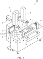
- Fig. 1 is a perspective view illustrating a configuration example of a robot system 100 according to Embodiment 1.
- Fig. 2 is a block diagram schematically illustrating a configuration example of a control system of the robot system 100.
- the robot system 100 is applicable to, for example, a production system adopting a cell production system in which a manufacturing cell is created for each process.
- the cell production system is a production system in which, in an assembling process, one or more worker(s) take(s) charge of the entire process of assembling the parts.
- Such a cell production system is easy to switch production items, and thus, suitable for a high-mix low-volume production.
- the robot system 100 is applied to a process of assembling one substrate to another substrate in a manufacturing process of an electronic device.
- the robot system 100 is provided with a cell unit 1 in which a plurality of manufacturing equipment (a robot 11 and a peripheral equipment 12 described later) are packaged as one cell unit, a portable information terminal 2, and a cradle 3.
- a cell unit 1 in which a plurality of manufacturing equipment (a robot 11 and a peripheral equipment 12 described later) are packaged as one cell unit, a portable information terminal 2, and a cradle 3.
- the cell unit 1 is a unit packaged corresponding to the use.
- the cell unit 1 is a unit packaged as a system for tightening screws, and performs a work of tightening screws.
- the cell unit 1 includes a manufacturing unit 10 and a unit controller 30.
- the manufacturing unit 10 includes the robot 11, the peripheral equipment 12, and a workbench 13, and the robot 11 and the peripheral equipment 12 perform a work of manufacturing products by operating in accordance with an operation program.
- the work bench 13 is a bench disposed in front of the robot 11 and on which the manufacturing work of the product is performed, and the work bench 13 includes a work area P at a center part thereof for manufacturing the product.
- the robot 11 is a horizontal articulated dual-arm robot provided with a pair of robotic arms 21, and the pair of robotic arms 21 are disposed so as to have a positional relationship therebetween similar to arms of a human. Therefore, the robot 11 can easily substitute a work by a worker in a manufacturing cell.
- a hand 22 is provided to a distal-end part of each robotic arm 21, and the hand 22 can be positioned at an arbitrary position within an operating range of the robotic arm 21 by operating the robotic arm 21.
- the hand 22 holds and releases a tool of various types so as to perform the manufacturing work using the tool.
- the pair of robotic arms 21 are supported by a pedestal 23.
- the unit controller 30 is provided in an inner space of the pedestal 23.
- the peripheral equipment 12 operates in accordance with the operation program configured to cause the peripheral equipment 12 to operate in cooperation with the robot 11, and the manufacturing work of the product is performed.
- the peripheral equipment 12 includes a screw supplying device 26 and an electric screw driver 27.
- the screw supplying device 26 is a device for supplying screws used for tightening the screws in order to assemble a substrate to another substrate.
- the screw supplying device 26 is disposed on the workbench 13 so as to be near the work area P of the workbench 13.
- the electric screw driver 27 includes a driver bit which is rotary driven based on an operation command, and can hold and release the screw supplied from the screw supplying device 26 with and from the driver bit based on the operation command.
- the electric screw driver 27 is placed and stored on a tool stand 29 provided near the work area P of the workbench 13 when the electric screw driver 27 is not used.
- a pair of part-supply-end notification buttons 28 are provided in front of the workbench 13.
- the part-supply-end notification buttons 28 are communicably connected to the unit controller 30.
- the unit controller 30 is communicably connected to the robot 11, the peripheral equipment 12, and the portable information terminal 2.
- the unit controller 30 includes a controller 31, a memory 32, and a unit communicating part 33.
- the unit controller 30 may be a sole control unit which executes a centralized control, or a plurality of control units which execute a distributed control.
- the controller 31 is comprised of a processor such as a microcontroller, a CPU, an MPU, a logic circuit, and a PLC.
- the controller 31 includes an operation mode setting module 41, an operation controlling module 42, and a display controlling module 43.
- the operation mode setting module 41, the operation controlling module 42, and the display controlling module 43 are functional blocks implemented by the controller 31 executing a given control program stored in the memory 32.
- the operation mode setting module 41 sets an operation mode to one of a plurality of operation modes including a teaching mode and a playback mode.
- the robot 11 is a robot controlled based on a teaching/playback system.
- a content and a process of the operation of the robot 11 are created and adjusted while the robot 11 is moved based on an operation command inputted manually by the worker, and an operation program including the information on the operation content and process of the robot 11 is created and edited.
- contents and processes of the operations of the robot 11 and the peripheral equipment 12 may be created and adjusted, and an operation program including the information on the operation contents and processes of the robot 11 and the peripheral equipment 12 may be created and edited.
- the operation program is played back so that the robot 11 and the peripheral equipment 12 perform the manufacturing work.
- the operation contents and processes of the robot 11 and the peripheral equipment 12 may be created and adjusted in order for the peripheral equipment 12 to cooperatively operate with the robot 11, by using a terminal other than the portable information terminal 2.
- the operation controlling module 42 controls the operation of the robot 11 based on the operation command inputted by the worker through an inputting part 61 of the portable information terminal 2 so as to sequentially execute the operation command. Moreover, in the playback mode, the operation controlling module 42 controls the robot 11 and the periphery equipment 12 in accordance with the operation program stored in the memory 32. That is, the operation controlling module 42 executes a sequential control of the robot 11 and the peripheral equipment 12 in the playback mode.
- the operation controlling module 42 includes a robot controlling module 51 for controlling the operation of the robot 11, and a peripheral equipment controlling module 52 for controlling the operation of the peripheral equipment 12. By the robot controlling module 51 and the peripheral equipment controlling module 52 operating cooperatively, collaborative operation of the robot 11 and the peripheral equipment 12 can be achieved.
- the robot controlling module 51 and the peripheral equipment controlling module 52 are included in single control unit.
- the robot controlling module 51 and the peripheral equipment controlling module 52 operate cooperatively as described below, when they control cooperative operation of the robot 11 and the electric screw driver 27 in an order of an operation by the robot 11 to position the electric screw driver 27 at a first tightening position, an operation by the electric screw driver 27 to tighten the screw, and an operation by the robot 11 to position the electric screw driver 27 at a second (subsequent) tightening position.
- the robot controlling module 51 controls the robotic arm 21 in accordance with the operation program so as to position the electric screw driver 27 held by the hand 22 at the first tightening position.
- the robot controlling module 51 notifies to the peripheral equipment controlling module 52 that the electric screw driver 27 is positioned at the first tightening position, and then, the robot controlling module 51 becomes in a stand-by state.
- the peripheral equipment controlling module 52 which received the notification controls the electric screw driver 27 in accordance with the operation program so as to carry out the screw tightening operation.
- the peripheral equipment controlling module 52 notifies to the robot controlling module 51 that the tightening of the screw is finished.
- the robot controlling module 51 which received the notification cancels the stand-by state, and controls the robotic arm 21 in accordance with the operation program so as to position the electric screw driver 27 held by the hand 22 at the second tightening position.
- the display controlling module 43 controls the portable information terminal 2 to display an operation screen 53 (see Fig. 3 ) for inputting the operation command on a displaying part 62 (described later) of the portable information terminal 2. Moreover, in the playback mode, the display controlling module 43 controls the portable information terminal 2 to display a screen different from the operation screen 53. In this embodiment, the display controlling module 43 controls the portable information terminal 2 in the playback mode to display on the displaying part 62 a manufacturing information displaying screen 54 (see Fig. 4 ) showing information on the manufacturing of the product. For example, the display controlling module 43 transmits the operation mode set by the operation mode setting module 41 to the portable information terminal 2 to control the portable information terminal 2.
- the memory 32 includes a memory such as a ROM and a RAM.
- the memory 32 stores given programs, and by the controller 31 reading and executing the programs, various processing are executed.
- the given programs include the operation contents and processes of the robot 11 and the peripheral equipment 12.
- the memory 32 stores a plurality of operation programs corresponding to various types of products so that the robot system 100 can perform manufacturing works of a plurality of types of products. Then, by the worker selecting the type of product to be manufactured, the operation program corresponding to this type is read from the memory 32.
- the unit communicating part 33 performs wireless communication with a terminal communicating part 67 (described later) of the portable information terminal 2.
- the controller 31 controls the unit communicating part 33 to transmit information including a manufacturing state of the product to the portable information terminal 2.
- the portable information terminal 2 is a tablet computer, for example.
- the portable information terminal 2 includes a touch-panel display unit 60 having the inputting part 61 and the displaying part 62, a terminal-side charging connector 63 (see Fig. 4 ), a terminal controller 66, and a memory 68.
- the portable information terminal 2 has a rechargeable battery, and operates using power supplied from the rechargeable battery. The rechargeable battery is charged by power supplied via the terminal-side charging connector 63 provided to the portable information terminal 2.
- the touch-panel display unit 60 is integrally provided with the displaying part 62 (e.g., a liquid-crystal display) which displays an image, and the inputting part 61 through which the worker detects a positional information of the screen displayed on the displaying part 62, and a well-known touch-panel display unit can be used as the touch-panel display unit 60. Therefore, the worker can input the operation command to operate the robot 11 by touching the screen based on the image information displayed on the displaying part 62. The operation command is accepted by the inputting part 61.
- the displaying part 62 e.g., a liquid-crystal display
- the portable information terminal 2 is formed in a substantially rectangular shape and in a size holdable by the worker with one hand when long sides are vertically oriented.
- the displaying part 62 of the touch-panel display unit 60 is also formed in a rectangular shape, and the touch-pane display unit 60 is disposed so that long sides of the displaying part 62 are oriented in the same direction as the long sides of the portable information terminal 2.
- Fig. 3 is a view illustrating one example of the operation screen 53 displayed on the touch-panel display unit 60.
- the operation screen 53 is a screen for inputting the operation command, and includes operation button images B1 for operating the robotic arms 21, operation button images B2 for registering teaching positions of the robotic arms 21, and operation button images B3 for operating the hands 22.
- the operation screen 53 includes operation button images B4 for rotating the electric screw drivers 27 which are the peripheral equipment 12, and operation button images B5 for sucking and releasing the screws to and from the driver bits of the electric screw drivers 27.
- the worker touches these operation buttons in the teaching mode so as to manually operate the robot 11 and the peripheral equipment 12, and thus, the worker can create and edit the operation program including the information on the operation contents and processes of the robot 11 and the peripheral equipment 12.
- the operation screen 53 is an image in a portrait orientation, and is laid out so that the portable information terminal 2 and the displaying part 62 are operated in the portrait orientation. Therefore, when the worker performs the teaching work, he/she can touch the touch-panel display unit 60 using one hand while holding the portable information terminal 2 using the other hand.
- Fig. 4 is a view illustrating one example of the manufacturing information displaying screen 54 displayed on the touch-panel display unit 60.
- the manufacturing information displaying screen 54 is a screen including the information on the manufacturing of the product, and includes an area A1 where a type of the product corresponding to the operation program executed by the unit controller 30 is displayed, an area A2 where a volume of manufacture of the product being manufactured is displayed, and an area A3 where a content of an abnormality when the abnormality occurs is displayed.
- the cell unit 1 operates in the playback mode, the worker can know the manufacturing state of the product through the manufacturing information displaying screen 54.
- the manufacturing information displaying screen 54 can include the information related to the manufacturing processes, the information related to the product, and the information related to the state of the manufacturing unit 10, and thus, the manufacturing work can be efficiently performed.
- the manufacturing information displaying screen 54 is an image in a landscape orientation, which can improve graspability of overall information on the manufacturing.
- the manufacturing information displaying screen 54 includes a start button B11 for inputting an operation command to execute the operation program, a stop button B12 for inputting an operation command to stop the execution of the operation program, and a return-to-origin button B13 for inputting an operation command to cause the robot 11 to return to the origin.
- a command related to the operation of the manufacturing unit 10 in the playback mode can also be inputted through the manufacturing information displaying screen 54.
- an abnormal reset button B14 is provided for deleting the content of the abnormality displayed in the area A3.
- An inquiry button B 15 is further provided for the worker to inquire the state of the robot system 100 to the robot system 100.
- the terminal controller 66 controls the displaying part 62 to display information on the operating state of the robot system 100. Therefore, the worker can easily know by touching the inquiry button B15 whether the robot system 100 is not working in appearance since it is in a stand-by state, etc., or the robot system 100 is in the stopped state.
- the terminal controller 66 is comprised of a processor such as a microcontroller, a CPU, an MPU, a logic circuit, and a PLC.
- the terminal controller 66 controls the displaying part 62 to display the screen corresponding to the operation mode received from the display controlling module 43 of the unit controller 30. That is, when the terminal controller 66 receives the input indicating that the operation mode is the teaching mode, it displays the operation screen 53. On the other hand, when the terminal controller 66 receives the input indicating that the operation mode is the playback mode, it displays the manufacturing information displaying screen 54. Moreover, the terminal controller 66 detects the operation command based on the content inputted to the inputting part 61.
- the portable information terminal 2 has a holding state detecting part which detects whether the portable information terminal 2 is held by a holding part 71 of the cradle 3 (described later).
- the holding state detecting part detects whether the terminal-side charging connector 63 is electrically connected to a cradle-side charging connector 72 (described later).
- the holding state detecting part is built in the terminal controller 66.
- the terminal communicating part 67 performs wireless communication with the unit communicating part 33 of the cell unit 1.
- the terminal controller 66 controls the terminal communicating part 67 to transmit to the cell unit 1 information on the holding state of the portable information terminal 2 by the cradle 3, and the information including the operation command inputted to the inputting part 61.
- the portable information terminal 2 may be a tablet computer possessed by the worker, and an application provided with a function to control the cell unit 1 may be installed in the tablet computer. Accordingly, the configuration of the robot system 100 can be simplified, which is advantageous for the manufacturing, and can lower a manufacturing cost.
- the memory 68 is configured similarly to the memory 32.
- the memory 68 stores a display program for generating the operation screen 53 and the manufacturing information displaying screen 54.
- the terminal controller 66 uses this display program and parameters related to the manufacturing information of the product received from the unit controller 30 in order to generate the manufacturing information displaying screen 54.
- the cradle 3 is a device for placing the portable information terminal 2 at a position easy to be seen by the worker in the manufacturing cell.
- the portable information terminal 2 is placed near a position where the worker stands in order to press the part-supply-end notification buttons 28.
- the cradle 3 includes, for example, the holding part 71 which can hold the portable information terminal 2 in the landscape orientation. Moreover, the cradle 3 includes the cradle-side charging connector 72 connectable with the terminal-side charging connector 63 to charge the portable information terminal 2 held by the holding part 71.
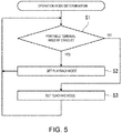
- Fig. 5 is a flowchart illustrating an operation example of a determining process of the operation mode.
- the controller 31 determines whether the portable information terminal 2 is held by the holding part 71 of the cradle 3 based on the detection result of the holding state detecting part, which is received from the portable information terminal 2 (Step S1).
- the controller 31 determines that the portable information terminal 2 is held by the holding part 71 (YES at Step S1), and the operation mode setting module 41 sets the operation mode to the playback mode (Step S2). Therefore, the operation controlling module 42 controls the robot 11 and the peripheral equipment 12 in accordance with the operation program stored in the memory 32. Note that actual operation of the robot 11 and the peripheral equipment 12 may be started after an operation command to start the operation of the robot 11 and the peripheral equipment 12 in accordance with the operation program is inputted to the inputting part 61. Moreover, the display controlling module 43 controls the portable information terminal 2 to display on the displaying part 62 of the portable information terminal 2 the manufacturing information displaying screen 54 for displaying the manufacturing information of the product. Then, the controller 31 again executes Step S1.
- the controller 31 determines that the portable information terminal 2 is not held by the holding part 71 (NO at Step S1), and the operation mode setting module 41 sets the operation mode to the teaching mode (Step S3).
- the unit controller 30 determines that the state where the portable information terminal 2 is held by the holding part 71 transits to the state where it is not held by the holding part 71, and thus, the operation mode setting module 41 sets the operation mode to the teaching mode. Therefore, the teaching can be started promptly.
- the operation controlling module 42 controls the operation of the robot 11 based on the operation command inputted manually by the worker.
- the display controlling module 43 controls the portable information terminal 2 to display on the displaying part 62 of the portable information terminal 2 the operation screen 53 for inputting the operation command.
- the controller 31 again executes Step S1.
- the operation controlling module 42 suspends the control of the robot 11 and the peripheral equipment 12 in accordance with the operation program, and sequentially controls the operation of the robot 11 based on the operation command inputted manually by the worker.
- the manufacturing unit 10 stops. That is, in an emergency, the manufacturing unit 10 can be emergently stopped by taking up the portable information terminal 2 from the cradle 3.
- the worker takes up the portable information terminal 2 from the cradle 3, grips the portable information terminal 2 in the portrait orientation with one hand, and stands at an arbitrary position around the robot 11 so as to teach the robot 11. Therefore, the worker can teach the robot 11 while watching it from a position easy to see the operation of the robot 11, and thereby, the teaching can be performed efficiently.
- a teach pendant for teaching a robot is not used in the playback mode, and is, for example, suspended from a housing of a robot controller. Furthermore, information on manufacturing is displayed on a display unit of exclusive use connected to a PLC, etc. when manufacturing products.
- the portable information terminal 2 since the portable information terminal 2 displays the manufacturing information of the product in a normal mode, the portable information terminal 2 used for the teaching in the teaching mode can be used also as a display unit for displaying the manufacturing information of the product in the playback mode. Therefore, the configuration of the robot system 100 can be simplified, and the manufacturing cost can be lowered.
- the robot system 100 includes the manufacturing unit 10, the portable information terminal 2, and the unit controller 30.
- the manufacturing unit 10 includes the robot 11 and the peripheral equipment 12 which operates cooperatively with the robot 11, and performs the work of manufacturing the product by operating in accordance with the operation program including the contents and processes of the operations of the robot 11 and the peripheral equipment 12.
- the portable information terminal 2 includes the displaying part 62 which displays information, and the inputting part 61 which accepts the operation command for operating the robot 11.
- the unit controller 30 is communicably connected to the robot 11, the peripheral equipment 12, and the portable information terminal 2, and includes the memory 32 storing the operation program, the operation mode setting module 41 which sets the operation mode to one of the plurality of operation modes including the teaching mode and the playback mode, the operation controlling module 42 which controls the robot 11 in the teaching mode based on the operation command, and controls the robot 11 and the peripheral equipment 12 in the playback mode in accordance with the operation program, and the display controlling module 43 which controls the portable information terminal 2 in the teaching mode to display on the displaying part 62 the operation screen 53 through which the operation command is inputted, and controls the portable information terminal 2 in the playback mode to display on the displaying part 62 the screen different from the operation screen 53.
- the portable information terminal 2 since the portable information terminal 2 displays the manufacturing information of the product in the normal mode, the portable information terminal 2 used for the teaching in the teaching mode can be used also as the display unit for displaying the manufacturing information of the product in the playback mode. Therefore, the configuration of the robot system 100 can be simplified, and the manufacturing cost can be lowered. Moreover, the robot system 100 can be used more easily.
- the screen different from the operation screen 53 may be the manufacturing information displaying screen 54 including the information on the manufacturing of the product.
- the worker can easily confirm the information related to the manufacturing of the product by using the portable information terminal 2.
- the information on the manufacturing may be at least one of the type of the manufactured product, the volume of manufacture of the product, and the content of abnormality when the abnormality occurs.
- the worker can more easily confirm the information related to the manufacturing of the product by using the portable information terminal 2.
- the robot system 100 may further include the cradle 3 having the holding part 71 which holds the portable information terminal 2, and the holding state detecting part which detects whether the portable information terminal 2 is held by the holding part 71.
- the operation mode setting module 41 may set the operation mode to the teaching mode.
- the teaching can be started promptly.
- the operation controlling module 42 may suspend the control of the robot 11 and the peripheral equipment 12 in accordance with the operation program.
- the manufacturing unit 10 can be emergently stopped by taking up the portable information terminal 2 from the cradle 3.
- Embodiment 2 a configuration and operation of Embodiment 2 are described focusing on differences from Embodiment 1.
- Fig. 6 is a block diagram schematically illustrating a configuration example of a control system of a robot system 200 according to Embodiment 2.
- the robot system 200 includes a plurality of cell units 1.
- the portable information terminal 2 is communicably connected to the unit controllers 30 of the plurality of cell units 1. Therefore, the portable information terminal 2 can be shared by the plurality of cell units 1, which simplifies the configuration of the robot system 100 and lowers the manufacturing cost.
- the robot system 200 may include a plurality of cell units 1 each including the manufacturing unit 10 and the unit controller 30, and configured to perform a given manufacturing work.
- the portable information terminal 2 may be communicably connected to the unit controllers 30 of the plurality of cell units 1.
- Embodiment 3 a configuration and operation of Embodiment 3 are described focusing on differences from Embodiment 1.
- Fig. 7 is a block diagram schematically illustrating a configuration example of a control system of a robot system 300 according to Embodiment 3.
- a peripheral equipment controller 352 which controls the operation of the peripheral equipment 12 of the robot system 300 is a programmable logic controller (PLC), and is a control unit independent from the operation controlling module 42.
- PLC programmable logic controller
- the peripheral equipment controller 352 is communicably connected to the controller 31, and controls the peripheral equipment 12 so that the peripheral equipment 12 operates cooperatively with the robot 11. Therefore, even when an amount of communication between the peripheral equipment 12 and the control unit which controls it increases, the unit controller 30 can stably control the peripheral equipment 12 to operate cooperatively with the robot 11.
- the display controlling module 43 may control the portable information terminal 2 to display a screen for guiding a method of using the robot system 100, a screen for introducing the robot system 100, and a screen for introducing the product manufactured by the robot system 100 or a service provided by the robot system 100.
- the cradle 3 may be communicably connected to the unit controller 30, and an emergency stop button may be provided for transmitting a signal to emergently stop the operation of the manufacturing unit 10, to the unit controller 30.
Landscapes
- Engineering & Computer Science (AREA)
- Physics & Mathematics (AREA)
- General Physics & Mathematics (AREA)
- Robotics (AREA)
- Automation & Control Theory (AREA)
- Mechanical Engineering (AREA)
- Human Computer Interaction (AREA)
- Theoretical Computer Science (AREA)
- Manufacturing & Machinery (AREA)
- General Engineering & Computer Science (AREA)
- Manipulator (AREA)
- Numerical Control (AREA)
Abstract
Description
- The present disclosure relates to a robot system and a method of controlling the robot system.
- Conventionally, robot operating devices for operating a robot are known (e.g., see Patent Document 1).
- This robot operating device is provided with a portable smart device including a touch-panel part for display and input, and a base member which is grippable with one hand and includes a placing part for detachably placing the smart device thereon so that the touch-panel part is exposed outside.
- [Patent Document 1]
JP2016-060018A - However, the robot operating device disclosed in
Patent Document 1 has a difficulty in confirming information on manufacturing of products when manufacturing the products in accordance with an operation program. - In order to solve the problem, a robot system according to one aspect of the present disclosure includes a manufacturing unit including a robot and a peripheral equipment configured to operate cooperatively with the robot, and configured to perform a work of manufacturing a product by operating in accordance with an operation program including contents and processes of the operations of the robot and the peripheral equipment, a portable information terminal including a displaying part configured to display information, and an inputting part configured to accept an operation command for operating the robot, and a unit controller communicably connected to the robot, the peripheral equipment, and the portable information terminal. The unit controller includes a memory storing the operation program, an operation mode setting module configured to set an operation mode to one of a plurality of operation modes including a teaching mode and a playback mode, an operation controlling module configured to control the operation of the robot in the teaching mode based on the operation command, and control the robot and the peripheral equipment in the playback mode in accordance with the operation program, and a display controlling module configured to control the portable information terminal in the teaching mode to display on the displaying part an operation screen through which the operation command is inputted, and control the portable information terminal in the playback mode to display on the displaying part a screen different from the operation screen.
- According to this configuration, since the portable information terminal displays the manufacturing information of the product in a normal mode, the portable information terminal used for the teaching in the teaching mode can be used also as a display unit for displaying the manufacturing information of the product in the playback mode. Therefore, the configuration of the robot system can be simplified, and the manufacturing cost can be lowered.
- The present disclosure achieves an effect of simplifying the configuration of the robot system.
-
-
Fig. 1 is a perspective view illustrating a configuration example of a robot system according toEmbodiment 1. -
Fig. 2 is a block diagram of a configuration example of a control system of the robot system illustrated inFig. 1 . -
Fig. 3 is a view illustrating one example of an operation screen of the robot system illustrated inFig. 1 . -
Fig. 4 is a view illustrating one example of a manufacturing information displaying screen of the robot system illustrated inFig. 1 . -
Fig. 5 is a flowchart illustrating an operation example of a determining process in an operation mode of the robot system illustrated inFig. 1 . -
Fig. 6 is a block diagram illustrating a configuration example of a control system of a robot system according toEmbodiment 2. -
Fig. 7 is a block diagram illustrating a configuration example of a control system of a robot system according toEmbodiment 3. - Hereinafter, embodiments are described with reference to the drawings. Note that the present disclosure is not limited to the embodiments described below. Moreover, the same reference characters are given to the same or corresponding components throughout the drawings to omit redundant description.
-
Fig. 1 is a perspective view illustrating a configuration example of arobot system 100 according toEmbodiment 1.Fig. 2 is a block diagram schematically illustrating a configuration example of a control system of therobot system 100. - The
robot system 100 is applicable to, for example, a production system adopting a cell production system in which a manufacturing cell is created for each process. The cell production system is a production system in which, in an assembling process, one or more worker(s) take(s) charge of the entire process of assembling the parts. Such a cell production system is easy to switch production items, and thus, suitable for a high-mix low-volume production. Below, one example is described in detail, in which therobot system 100 is applied to a process of assembling one substrate to another substrate in a manufacturing process of an electronic device. - As illustrated in
Figs. 1 and2 , therobot system 100 is provided with acell unit 1 in which a plurality of manufacturing equipment (arobot 11 and aperipheral equipment 12 described later) are packaged as one cell unit, aportable information terminal 2, and acradle 3. - The
cell unit 1 is a unit packaged corresponding to the use. In this embodiment, thecell unit 1 is a unit packaged as a system for tightening screws, and performs a work of tightening screws. Thecell unit 1 includes amanufacturing unit 10 and aunit controller 30. - The
manufacturing unit 10 includes therobot 11, theperipheral equipment 12, and aworkbench 13, and therobot 11 and theperipheral equipment 12 perform a work of manufacturing products by operating in accordance with an operation program. Thework bench 13 is a bench disposed in front of therobot 11 and on which the manufacturing work of the product is performed, and thework bench 13 includes a work area P at a center part thereof for manufacturing the product. - The
robot 11 is a horizontal articulated dual-arm robot provided with a pair ofrobotic arms 21, and the pair ofrobotic arms 21 are disposed so as to have a positional relationship therebetween similar to arms of a human. Therefore, therobot 11 can easily substitute a work by a worker in a manufacturing cell. Ahand 22 is provided to a distal-end part of eachrobotic arm 21, and thehand 22 can be positioned at an arbitrary position within an operating range of therobotic arm 21 by operating therobotic arm 21. Thehand 22 holds and releases a tool of various types so as to perform the manufacturing work using the tool. The pair ofrobotic arms 21 are supported by apedestal 23. Theunit controller 30 is provided in an inner space of thepedestal 23. - The
peripheral equipment 12 operates in accordance with the operation program configured to cause theperipheral equipment 12 to operate in cooperation with therobot 11, and the manufacturing work of the product is performed. In this embodiment, theperipheral equipment 12 includes ascrew supplying device 26 and anelectric screw driver 27. - The
screw supplying device 26 is a device for supplying screws used for tightening the screws in order to assemble a substrate to another substrate. Thescrew supplying device 26 is disposed on theworkbench 13 so as to be near the work area P of theworkbench 13. Theelectric screw driver 27 includes a driver bit which is rotary driven based on an operation command, and can hold and release the screw supplied from thescrew supplying device 26 with and from the driver bit based on the operation command. Theelectric screw driver 27 is placed and stored on atool stand 29 provided near the work area P of theworkbench 13 when theelectric screw driver 27 is not used. - Moreover, in front of the
workbench 13, a pair of part-supply-end notification buttons 28 are provided. The part-supply-end notification buttons 28 are communicably connected to theunit controller 30. When the worker places one substrate and another substrate to be assembled to the one substrate in the work area P of theworkbench 13, and presses the pair of part-supply-end notification buttons 28 with both his/her hands, a signal to notify that these two substrates are placed is transmitted to theunit controller 30, and a permission to start the screw tightening work is notified to therobot system 100. Therefore, therobot system 100 and the worker can cooperatively perform the work related to the manufacturing of the product. In the manufacturing process of the product, process which is difficult to be performed by therobot system 100 is performed by the worker, and then, by the worker pressing the part-supply-end notification buttons 28, the subsequent process which can be performed easily by therobot system 100 can be performed by therobot system 100. - The
unit controller 30 is communicably connected to therobot 11, theperipheral equipment 12, and theportable information terminal 2. Theunit controller 30 includes acontroller 31, amemory 32, and aunit communicating part 33. Theunit controller 30 may be a sole control unit which executes a centralized control, or a plurality of control units which execute a distributed control. - The
controller 31 is comprised of a processor such as a microcontroller, a CPU, an MPU, a logic circuit, and a PLC. Thecontroller 31 includes an operationmode setting module 41, anoperation controlling module 42, and adisplay controlling module 43. The operationmode setting module 41, theoperation controlling module 42, and thedisplay controlling module 43 are functional blocks implemented by thecontroller 31 executing a given control program stored in thememory 32. - The operation
mode setting module 41 sets an operation mode to one of a plurality of operation modes including a teaching mode and a playback mode. Therobot 11 is a robot controlled based on a teaching/playback system. In the teaching mode, a content and a process of the operation of therobot 11 are created and adjusted while therobot 11 is moved based on an operation command inputted manually by the worker, and an operation program including the information on the operation content and process of therobot 11 is created and edited. Moreover, in the teaching mode, in order for theperipheral equipment 12 to cooperatively operate with therobot 11, contents and processes of the operations of therobot 11 and theperipheral equipment 12 may be created and adjusted, and an operation program including the information on the operation contents and processes of therobot 11 and theperipheral equipment 12 may be created and edited. Meanwhile, in the playback mode, the operation program is played back so that therobot 11 and theperipheral equipment 12 perform the manufacturing work. Note that the operation contents and processes of therobot 11 and theperipheral equipment 12 may be created and adjusted in order for theperipheral equipment 12 to cooperatively operate with therobot 11, by using a terminal other than theportable information terminal 2. - In the teaching mode, the
operation controlling module 42 controls the operation of therobot 11 based on the operation command inputted by the worker through an inputtingpart 61 of theportable information terminal 2 so as to sequentially execute the operation command. Moreover, in the playback mode, theoperation controlling module 42 controls therobot 11 and theperiphery equipment 12 in accordance with the operation program stored in thememory 32. That is, theoperation controlling module 42 executes a sequential control of therobot 11 and theperipheral equipment 12 in the playback mode. In this embodiment, theoperation controlling module 42 includes arobot controlling module 51 for controlling the operation of therobot 11, and a peripheralequipment controlling module 52 for controlling the operation of theperipheral equipment 12. By therobot controlling module 51 and the peripheralequipment controlling module 52 operating cooperatively, collaborative operation of therobot 11 and theperipheral equipment 12 can be achieved. In this embodiment, therobot controlling module 51 and the peripheralequipment controlling module 52 are included in single control unit. - For example, the
robot controlling module 51 and the peripheralequipment controlling module 52 operate cooperatively as described below, when they control cooperative operation of therobot 11 and theelectric screw driver 27 in an order of an operation by therobot 11 to position theelectric screw driver 27 at a first tightening position, an operation by theelectric screw driver 27 to tighten the screw, and an operation by therobot 11 to position theelectric screw driver 27 at a second (subsequent) tightening position. First, therobot controlling module 51 controls therobotic arm 21 in accordance with the operation program so as to position theelectric screw driver 27 held by thehand 22 at the first tightening position. Then, therobot controlling module 51 notifies to the peripheralequipment controlling module 52 that theelectric screw driver 27 is positioned at the first tightening position, and then, therobot controlling module 51 becomes in a stand-by state. Next, the peripheralequipment controlling module 52 which received the notification controls theelectric screw driver 27 in accordance with the operation program so as to carry out the screw tightening operation. Then, when the tightening of the screw is finished, the peripheralequipment controlling module 52 notifies to therobot controlling module 51 that the tightening of the screw is finished. Next, therobot controlling module 51 which received the notification cancels the stand-by state, and controls therobotic arm 21 in accordance with the operation program so as to position theelectric screw driver 27 held by thehand 22 at the second tightening position. - In the teaching mode, the
display controlling module 43 controls theportable information terminal 2 to display an operation screen 53 (seeFig. 3 ) for inputting the operation command on a displaying part 62 (described later) of theportable information terminal 2. Moreover, in the playback mode, thedisplay controlling module 43 controls theportable information terminal 2 to display a screen different from theoperation screen 53. In this embodiment, thedisplay controlling module 43 controls theportable information terminal 2 in the playback mode to display on the displaying part 62 a manufacturing information displaying screen 54 (seeFig. 4 ) showing information on the manufacturing of the product. For example, thedisplay controlling module 43 transmits the operation mode set by the operationmode setting module 41 to theportable information terminal 2 to control theportable information terminal 2. - The
memory 32 includes a memory such as a ROM and a RAM. Thememory 32 stores given programs, and by thecontroller 31 reading and executing the programs, various processing are executed. The given programs include the operation contents and processes of therobot 11 and theperipheral equipment 12. Note that thememory 32 stores a plurality of operation programs corresponding to various types of products so that therobot system 100 can perform manufacturing works of a plurality of types of products. Then, by the worker selecting the type of product to be manufactured, the operation program corresponding to this type is read from thememory 32. - The
unit communicating part 33 performs wireless communication with a terminal communicating part 67 (described later) of theportable information terminal 2. Thecontroller 31 controls theunit communicating part 33 to transmit information including a manufacturing state of the product to theportable information terminal 2. - As illustrated in
Figs. 1 and2 , theportable information terminal 2 is a tablet computer, for example. Theportable information terminal 2 includes a touch-panel display unit 60 having the inputtingpart 61 and the displayingpart 62, a terminal-side charging connector 63 (seeFig. 4 ), aterminal controller 66, and amemory 68. Theportable information terminal 2 has a rechargeable battery, and operates using power supplied from the rechargeable battery. The rechargeable battery is charged by power supplied via the terminal-side charging connector 63 provided to theportable information terminal 2. - The touch-
panel display unit 60 is integrally provided with the displaying part 62 (e.g., a liquid-crystal display) which displays an image, and the inputtingpart 61 through which the worker detects a positional information of the screen displayed on the displayingpart 62, and a well-known touch-panel display unit can be used as the touch-panel display unit 60. Therefore, the worker can input the operation command to operate therobot 11 by touching the screen based on the image information displayed on the displayingpart 62. The operation command is accepted by the inputtingpart 61. - As illustrated in
Figs. 1 and4 , theportable information terminal 2 is formed in a substantially rectangular shape and in a size holdable by the worker with one hand when long sides are vertically oriented. Moreover, the displayingpart 62 of the touch-panel display unit 60 is also formed in a rectangular shape, and the touch-pane display unit 60 is disposed so that long sides of the displayingpart 62 are oriented in the same direction as the long sides of theportable information terminal 2. -
Fig. 3 is a view illustrating one example of theoperation screen 53 displayed on the touch-panel display unit 60. As illustrated inFig. 3 , theoperation screen 53 is a screen for inputting the operation command, and includes operation button images B1 for operating therobotic arms 21, operation button images B2 for registering teaching positions of therobotic arms 21, and operation button images B3 for operating thehands 22. Moreover, theoperation screen 53 includes operation button images B4 for rotating theelectric screw drivers 27 which are theperipheral equipment 12, and operation button images B5 for sucking and releasing the screws to and from the driver bits of theelectric screw drivers 27. The worker touches these operation buttons in the teaching mode so as to manually operate therobot 11 and theperipheral equipment 12, and thus, the worker can create and edit the operation program including the information on the operation contents and processes of therobot 11 and theperipheral equipment 12. - Note that the
operation screen 53 is an image in a portrait orientation, and is laid out so that theportable information terminal 2 and the displayingpart 62 are operated in the portrait orientation. Therefore, when the worker performs the teaching work, he/she can touch the touch-panel display unit 60 using one hand while holding theportable information terminal 2 using the other hand. -
Fig. 4 is a view illustrating one example of the manufacturinginformation displaying screen 54 displayed on the touch-panel display unit 60. As illustrated inFig. 4 , the manufacturinginformation displaying screen 54 is a screen including the information on the manufacturing of the product, and includes an area A1 where a type of the product corresponding to the operation program executed by theunit controller 30 is displayed, an area A2 where a volume of manufacture of the product being manufactured is displayed, and an area A3 where a content of an abnormality when the abnormality occurs is displayed. When thecell unit 1 operates in the playback mode, the worker can know the manufacturing state of the product through the manufacturinginformation displaying screen 54. Accordingly, the manufacturinginformation displaying screen 54 can include the information related to the manufacturing processes, the information related to the product, and the information related to the state of themanufacturing unit 10, and thus, the manufacturing work can be efficiently performed. Note that the manufacturinginformation displaying screen 54 is an image in a landscape orientation, which can improve graspability of overall information on the manufacturing. - Note that the manufacturing
information displaying screen 54 includes a start button B11 for inputting an operation command to execute the operation program, a stop button B12 for inputting an operation command to stop the execution of the operation program, and a return-to-origin button B13 for inputting an operation command to cause therobot 11 to return to the origin. A command related to the operation of themanufacturing unit 10 in the playback mode can also be inputted through the manufacturinginformation displaying screen 54. Moreover, an abnormal reset button B14 is provided for deleting the content of the abnormality displayed in the area A3. An inquiry button B 15 is further provided for the worker to inquire the state of therobot system 100 to therobot system 100. When the worker touches the inquiry button B15, theterminal controller 66 controls the displayingpart 62 to display information on the operating state of therobot system 100. Therefore, the worker can easily know by touching the inquiry button B15 whether therobot system 100 is not working in appearance since it is in a stand-by state, etc., or therobot system 100 is in the stopped state. - The
terminal controller 66 is comprised of a processor such as a microcontroller, a CPU, an MPU, a logic circuit, and a PLC. Theterminal controller 66 controls the displayingpart 62 to display the screen corresponding to the operation mode received from thedisplay controlling module 43 of theunit controller 30. That is, when theterminal controller 66 receives the input indicating that the operation mode is the teaching mode, it displays theoperation screen 53. On the other hand, when theterminal controller 66 receives the input indicating that the operation mode is the playback mode, it displays the manufacturinginformation displaying screen 54. Moreover, theterminal controller 66 detects the operation command based on the content inputted to the inputtingpart 61. - Moreover, the
portable information terminal 2 has a holding state detecting part which detects whether theportable information terminal 2 is held by a holdingpart 71 of the cradle 3 (described later). In this embodiment, the holding state detecting part detects whether the terminal-side charging connector 63 is electrically connected to a cradle-side charging connector 72 (described later). The holding state detecting part is built in theterminal controller 66. - The
terminal communicating part 67 performs wireless communication with theunit communicating part 33 of thecell unit 1. Theterminal controller 66 controls theterminal communicating part 67 to transmit to thecell unit 1 information on the holding state of theportable information terminal 2 by thecradle 3, and the information including the operation command inputted to the inputtingpart 61. - Note that the
portable information terminal 2 may be a tablet computer possessed by the worker, and an application provided with a function to control thecell unit 1 may be installed in the tablet computer. Accordingly, the configuration of therobot system 100 can be simplified, which is advantageous for the manufacturing, and can lower a manufacturing cost. - The
memory 68 is configured similarly to thememory 32. Thememory 68 stores a display program for generating theoperation screen 53 and the manufacturinginformation displaying screen 54. Theterminal controller 66 uses this display program and parameters related to the manufacturing information of the product received from theunit controller 30 in order to generate the manufacturinginformation displaying screen 54. - As illustrated in
Fig. 1 , thecradle 3 is a device for placing theportable information terminal 2 at a position easy to be seen by the worker in the manufacturing cell. For example, theportable information terminal 2 is placed near a position where the worker stands in order to press the part-supply-end notification buttons 28. - The
cradle 3 includes, for example, the holdingpart 71 which can hold theportable information terminal 2 in the landscape orientation. Moreover, thecradle 3 includes the cradle-side charging connector 72 connectable with the terminal-side charging connector 63 to charge theportable information terminal 2 held by the holdingpart 71. - Next, an operation example of the
robot system 100 is described. -
Fig. 5 is a flowchart illustrating an operation example of a determining process of the operation mode. - First, the
controller 31 determines whether theportable information terminal 2 is held by the holdingpart 71 of thecradle 3 based on the detection result of the holding state detecting part, which is received from the portable information terminal 2 (Step S1). - Then, when the holding state detecting part detects that the terminal-
side charging connector 63 and the cradle-side charging connector 72 are electrically connected to each other, thecontroller 31 determines that theportable information terminal 2 is held by the holding part 71 (YES at Step S1), and the operationmode setting module 41 sets the operation mode to the playback mode (Step S2). Therefore, theoperation controlling module 42 controls therobot 11 and theperipheral equipment 12 in accordance with the operation program stored in thememory 32. Note that actual operation of therobot 11 and theperipheral equipment 12 may be started after an operation command to start the operation of therobot 11 and theperipheral equipment 12 in accordance with the operation program is inputted to the inputtingpart 61. Moreover, thedisplay controlling module 43 controls theportable information terminal 2 to display on the displayingpart 62 of theportable information terminal 2 the manufacturinginformation displaying screen 54 for displaying the manufacturing information of the product. Then, thecontroller 31 again executes Step S1. - As described above, in the playback mode where the
portable information terminal 2 is held by thecradle 3, since the terminal-side charging connector 63 of theportable information terminal 2 is connected to the cradle-side charging connector 72 so as to be charged, running out of the battery can be prevented. - Then, when the holding state detecting part detects that the connection between the terminal-
side charging connector 63 and the cradle-side charging connector 72 is cancelled, thecontroller 31 determines that theportable information terminal 2 is not held by the holding part 71 (NO at Step S1), and the operationmode setting module 41 sets the operation mode to the teaching mode (Step S3). That is, when the holding state detecting part detects that the electrical connection between the terminal-side charging connector 63 and the cradle-side charging connector 72 is cancelled, for example, by the worker taking up theportable information terminal 2 held by thecradle 3, theunit controller 30 determines that the state where theportable information terminal 2 is held by the holdingpart 71 transits to the state where it is not held by the holdingpart 71, and thus, the operationmode setting module 41 sets the operation mode to the teaching mode. Therefore, the teaching can be started promptly. Then, theoperation controlling module 42 controls the operation of therobot 11 based on the operation command inputted manually by the worker. Moreover, thedisplay controlling module 43 controls theportable information terminal 2 to display on the displayingpart 62 of theportable information terminal 2 theoperation screen 53 for inputting the operation command. Then, thecontroller 31 again executes Step S1. - Moreover, corresponding to the setting to the teaching mode, the
operation controlling module 42 suspends the control of therobot 11 and theperipheral equipment 12 in accordance with the operation program, and sequentially controls the operation of therobot 11 based on the operation command inputted manually by the worker. Thus, for example, in a state where the operation command is not given immediately after the worker takes up theportable information terminal 2 held by thecradle 3, themanufacturing unit 10 stops. That is, in an emergency, themanufacturing unit 10 can be emergently stopped by taking up theportable information terminal 2 from thecradle 3. - Then, the worker takes up the
portable information terminal 2 from thecradle 3, grips theportable information terminal 2 in the portrait orientation with one hand, and stands at an arbitrary position around therobot 11 so as to teach therobot 11. Therefore, the worker can teach therobot 11 while watching it from a position easy to see the operation of therobot 11, and thereby, the teaching can be performed efficiently. - Moreover, conventionally, a teach pendant for teaching a robot is not used in the playback mode, and is, for example, suspended from a housing of a robot controller. Furthermore, information on manufacturing is displayed on a display unit of exclusive use connected to a PLC, etc. when manufacturing products. However, in this embodiment, since the
portable information terminal 2 displays the manufacturing information of the product in a normal mode, theportable information terminal 2 used for the teaching in the teaching mode can be used also as a display unit for displaying the manufacturing information of the product in the playback mode. Therefore, the configuration of therobot system 100 can be simplified, and the manufacturing cost can be lowered. - As described above, the
robot system 100 includes themanufacturing unit 10, theportable information terminal 2, and theunit controller 30. Themanufacturing unit 10 includes therobot 11 and theperipheral equipment 12 which operates cooperatively with therobot 11, and performs the work of manufacturing the product by operating in accordance with the operation program including the contents and processes of the operations of therobot 11 and theperipheral equipment 12. Theportable information terminal 2 includes the displayingpart 62 which displays information, and the inputtingpart 61 which accepts the operation command for operating therobot 11. Theunit controller 30 is communicably connected to therobot 11, theperipheral equipment 12, and theportable information terminal 2, and includes thememory 32 storing the operation program, the operationmode setting module 41 which sets the operation mode to one of the plurality of operation modes including the teaching mode and the playback mode, theoperation controlling module 42 which controls therobot 11 in the teaching mode based on the operation command, and controls therobot 11 and theperipheral equipment 12 in the playback mode in accordance with the operation program, and thedisplay controlling module 43 which controls theportable information terminal 2 in the teaching mode to display on the displayingpart 62 theoperation screen 53 through which the operation command is inputted, and controls theportable information terminal 2 in the playback mode to display on the displayingpart 62 the screen different from theoperation screen 53. - According to this configuration, since the
portable information terminal 2 displays the manufacturing information of the product in the normal mode, theportable information terminal 2 used for the teaching in the teaching mode can be used also as the display unit for displaying the manufacturing information of the product in the playback mode. Therefore, the configuration of therobot system 100 can be simplified, and the manufacturing cost can be lowered. Moreover, therobot system 100 can be used more easily. - The screen different from the
operation screen 53 may be the manufacturinginformation displaying screen 54 including the information on the manufacturing of the product. - According to this configuration, the worker can easily confirm the information related to the manufacturing of the product by using the
portable information terminal 2. - The information on the manufacturing may be at least one of the type of the manufactured product, the volume of manufacture of the product, and the content of abnormality when the abnormality occurs.
- According to this configuration, the worker can more easily confirm the information related to the manufacturing of the product by using the
portable information terminal 2. - The
robot system 100 may further include thecradle 3 having the holdingpart 71 which holds theportable information terminal 2, and the holding state detecting part which detects whether theportable information terminal 2 is held by the holdingpart 71. When theunit controller 30 determines, based on the detection result of the holding state detecting part, that the state in which theportable information terminal 2 is held by the holdingpart 71 transits to the state in which it is not held, the operationmode setting module 41 may set the operation mode to the teaching mode. - According to this configuration, the teaching can be started promptly.
- When it is determined based on the detection result of the holding state detecting part that the state where the
portable information terminal 2 is held by the holdingpart 71 transits to the state where it is not held, theoperation controlling module 42 may suspend the control of therobot 11 and theperipheral equipment 12 in accordance with the operation program. - According to this configuration, the
manufacturing unit 10 can be emergently stopped by taking up theportable information terminal 2 from thecradle 3. - Below, a configuration and operation of
Embodiment 2 are described focusing on differences fromEmbodiment 1. -
Fig. 6 is a block diagram schematically illustrating a configuration example of a control system of arobot system 200 according toEmbodiment 2. In this embodiment, therobot system 200 includes a plurality ofcell units 1. - Then, the
portable information terminal 2 is communicably connected to theunit controllers 30 of the plurality ofcell units 1. Therefore, theportable information terminal 2 can be shared by the plurality ofcell units 1, which simplifies the configuration of therobot system 100 and lowers the manufacturing cost. - As described above, the
robot system 200 may include a plurality ofcell units 1 each including themanufacturing unit 10 and theunit controller 30, and configured to perform a given manufacturing work. Theportable information terminal 2 may be communicably connected to theunit controllers 30 of the plurality ofcell units 1. - Below, a configuration and operation of
Embodiment 3 are described focusing on differences fromEmbodiment 1. -
Fig. 7 is a block diagram schematically illustrating a configuration example of a control system of arobot system 300 according toEmbodiment 3. - In this embodiment, a
peripheral equipment controller 352 which controls the operation of theperipheral equipment 12 of therobot system 300 is a programmable logic controller (PLC), and is a control unit independent from theoperation controlling module 42. Theperipheral equipment controller 352 is communicably connected to thecontroller 31, and controls theperipheral equipment 12 so that theperipheral equipment 12 operates cooperatively with therobot 11. Therefore, even when an amount of communication between theperipheral equipment 12 and the control unit which controls it increases, theunit controller 30 can stably control theperipheral equipment 12 to operate cooperatively with therobot 11. - The
display controlling module 43 may control theportable information terminal 2 to display a screen for guiding a method of using therobot system 100, a screen for introducing therobot system 100, and a screen for introducing the product manufactured by therobot system 100 or a service provided by therobot system 100. - The
cradle 3 may be communicably connected to theunit controller 30, and an emergency stop button may be provided for transmitting a signal to emergently stop the operation of themanufacturing unit 10, to theunit controller 30. - It is apparent for a person skilled in the art from the above description that many improvements and other embodiments of the present disclosure are possible. Therefore, the above description is to be interpreted only as illustration, and it is provided in order to teach a person skilled in the art the best mode to implement the present disclosure. The details of the structures and/or the functions may be substantially changed, without departing from the spirit of the present disclosure.
-
- 1
- Cell Unit
- 2
- Portable Information Terminal
- 3
- Cradle
- 10
- Manufacturing Unit
- 11
- Robot
- 12
- Peripheral Equipment
- 30
- Unit Controller
- 31
- Controller
- 32
- Memory
- 41
- Operation Mode Setting Module
- 42
- Operation Controlling Module
- 43
- Display Controlling Module
- 53
- Operation Screen
- 54
- Manufacturing Information Displaying Screen
- 61
- Inputting Part
- 62
- Displaying Part
- 66
- Terminal Controller
- 68
- Memory
- 71
- Holding Part
- 100
- Robot System
Claims (7)
- A robot system, comprising:a manufacturing unit including a robot and a peripheral equipment configured to operate cooperatively with the robot, and configured to perform a work of manufacturing a product by operating in accordance with an operation program including contents and processes of the operations of the robot and the peripheral equipment;a portable information terminal including a displaying part configured to display information, and an inputting part configured to accept an operation command for operating the robot; anda unit controller communicably connected to the robot, the peripheral equipment, and the portable information terminal, including:a memory storing the operation program;an operation mode setting module configured to set an operation mode to one of a plurality of operation modes including a teaching mode and a playback mode;an operation controlling module configured to control the operation of the robot in the teaching mode based on the operation command, and control the robot and the peripheral equipment in the playback mode in accordance with the operation program; anda display controlling module configured to control the portable information terminal in the teaching mode to display on the displaying part an operation screen through which the operation command is inputted, and control the portable information terminal in the playback mode to display on the displaying part a screen different from the operation screen.
- The robot system of claim 1, wherein the screen different from the operation screen is a manufacturing information displaying screen including information on the manufacturing of the product.
- The robot system of claim 2, wherein the information on the manufacturing is at least one of a type of the manufactured product, a volume of manufacture of the product, and a content of an abnormality when the abnormality occurs.
- The robot system of any one of claims 1 to 3, further comprising:a cradle including a holding part configured to hold the portable information terminal; anda holding state detecting part configured to detect whether the portable information terminal is held by the holding part,wherein when the unit controller determines, based on a detection result of the holding state detecting part, that a state in which the portable information terminal is held by the holding part transits to a state in which the portable information terminal is not held by the holding part, the operation mode setting module sets the operation mode to the teaching mode.
- The robot system of claim 4, wherein when it is determined based on the detection result of the holding state detecting part that the state in which the portable information terminal is held by the holding part transits to the state in which the portable information terminal is not held by the holding part, the operation controlling module suspends the control of the robot and the peripheral equipment in accordance with the operation program.
- The robot system of any one of claims 1 to 5, further comprising a plurality of cell units each including the manufacturing unit and the unit controller, and configured to perform a given manufacturing work,
wherein the portable information terminal is communicably connected to the unit controllers of the plurality of cell units. - A method of controlling a robot system including:a manufacturing unit including a robot and a peripheral equipment configured to operate cooperatively with the robot, and configured to perform a work of manufacturing a product by operating in accordance with an operation program including contents and processes of the operations of the robot and the peripheral equipment;a portable information terminal including a displaying part configured to display information, and an inputting part configured to accept an operation command for operating the robot;a cradle including a holding part configured to hold the portable information terminal;a holding state detecting part configured to detect whether the portable information terminal is held by the holding part; anda unit controller communicably connected to the robot, the peripheral equipment, and the portable information terminal, including:a memory storing the operation program;an operation mode setting module configured to set an operation mode to one of a plurality of operation modes including a teaching mode and a playback mode;an operation controlling module configured to control the operation of the robot in the teaching mode based on the operation command, and control the robot and the peripheral equipment in the playback mode in accordance with the operation program; anda display controlling module configured to control the portable information terminal in the teaching mode to display on the displaying part an operation screen through which the operation command is inputted, and control the portable information terminal in the playback mode to display on the displaying part a screen different from the operation screen,the method comprising the steps of:determining, based on a detection result of the holding state detecting part, whether a state in which the portable information terminal is held by the holding part transits to a state in which the portable information terminal is not held by the holding part; andsetting the operation mode to the teaching mode by the operation mode setting module when determined that the state in which the portable information terminal is held by the holding part transits to the state in which the portable information terminal is not held by the holding part.
Applications Claiming Priority (2)
| Application Number | Priority Date | Filing Date | Title |
|---|---|---|---|
| JP2018105342A JP7141857B2 (en) | 2018-05-31 | 2018-05-31 | ROBOT SYSTEM AND ROBOT SYSTEM CONTROL METHOD |
| PCT/JP2019/021666 WO2019230933A1 (en) | 2018-05-31 | 2019-05-31 | Robot system, and robot system control method |
Publications (3)
| Publication Number | Publication Date |
|---|---|
| EP3804917A1 true EP3804917A1 (en) | 2021-04-14 |
| EP3804917A4 EP3804917A4 (en) | 2022-03-02 |
| EP3804917B1 EP3804917B1 (en) | 2024-07-10 |
Family
ID=68697523
Family Applications (1)
| Application Number | Title | Priority Date | Filing Date |
|---|---|---|---|
| EP19810195.8A Active EP3804917B1 (en) | 2018-05-31 | 2019-05-31 | Robot system and method for controlling the robot system |
Country Status (7)
| Country | Link |
|---|---|
| US (1) | US11904454B2 (en) |
| EP (1) | EP3804917B1 (en) |
| JP (1) | JP7141857B2 (en) |
| KR (1) | KR102626064B1 (en) |
| CN (1) | CN112203808B (en) |
| TW (1) | TWI714109B (en) |
| WO (1) | WO2019230933A1 (en) |
Families Citing this family (8)
| Publication number | Priority date | Publication date | Assignee | Title |
|---|---|---|---|---|
| JP6918847B2 (en) * | 2019-01-11 | 2021-08-11 | ファナック株式会社 | Machine teaching terminal, teaching system, program and safety confirmation method used for teaching machines |
| JP7188407B2 (en) * | 2020-03-25 | 2022-12-13 | ブラザー工業株式会社 | Machine tools and machine tool control methods |
| DE112021002584B4 (en) | 2020-04-27 | 2025-03-20 | Fanuc Corporation | Mounting system |
| JP7813108B2 (en) * | 2021-08-31 | 2026-02-12 | 川崎重工業株式会社 | Operation terminal, robot system and computer program |
| JP7831079B2 (en) * | 2022-03-30 | 2026-03-17 | セイコーエプソン株式会社 | Teaching pendant |
| EP4325309A1 (en) * | 2022-08-17 | 2024-02-21 | fruitcore robotics GmbH | System for controlling operation of an automation component |
| JP2024039133A (en) * | 2022-09-09 | 2024-03-22 | 株式会社ディスコ | processing equipment |
| KR102558102B1 (en) * | 2022-11-29 | 2023-07-21 | 최한수 | User-configurable automated process control system |
Family Cites Families (17)
| Publication number | Priority date | Publication date | Assignee | Title |
|---|---|---|---|---|
| FR2325953A1 (en) * | 1975-09-29 | 1977-04-22 | Thomson Brandt | OPTICAL FOCUSING SENSOR AND FOCUSING DEVICE INCLUDING SUCH A SENSOR |
| JPH0615589A (en) * | 1992-07-03 | 1994-01-25 | Daihen Corp | Industrial robot controller |
| JP2003039359A (en) | 2001-07-26 | 2003-02-13 | Matsushita Electric Ind Co Ltd | Robot controller |
| DE602005006749D1 (en) * | 2005-04-19 | 2008-06-26 | Comau Spa | Method for controlling industrial robots and appropriately controlled robots, robotic systems and computer programs |
| JP4609651B2 (en) * | 2005-05-19 | 2011-01-12 | 株式会社安川電機 | Automatic machine system and communication control method thereof |
| WO2010045968A1 (en) * | 2008-10-21 | 2010-04-29 | Abb Technology Ab | A robot system with a teach pendant |
| US8606334B2 (en) * | 2010-08-23 | 2013-12-10 | Gn Netcom A/S | Mass deployment of communication headset systems |
| JP5516563B2 (en) * | 2011-12-13 | 2014-06-11 | 株式会社安川電機 | Robot system |
| KR101321601B1 (en) * | 2013-02-12 | 2013-10-28 | 주식회사 아진엑스텍 | Controller for multiple robot using wireless teaching pendant and method for controlling thereof |
| JP5632035B2 (en) * | 2013-03-29 | 2014-11-26 | 沖電気工業株式会社 | Remote work support system and remote work support program |
| JP6565151B2 (en) | 2014-09-19 | 2019-08-28 | 株式会社デンソーウェーブ | Industrial robot operation device |
| JP5926344B2 (en) | 2014-09-22 | 2016-05-25 | ファナック株式会社 | Robot controller that prevents problems related to robots during emergency stops |
| JP6441061B2 (en) * | 2014-12-16 | 2018-12-19 | 株式会社ダイヘン | Machine control system and user interface setting method of machine control system |
| CN107111338B (en) | 2015-01-16 | 2019-04-16 | 三菱电机株式会社 | Bracket and terminal device control method |
| WO2017085897A1 (en) * | 2015-11-16 | 2017-05-26 | 川崎重工業株式会社 | Manufacturing system, construction method of manufacturing system, end effector, robot, and robot operating method |
| US10903107B2 (en) * | 2017-07-11 | 2021-01-26 | Brooks Automation, Inc. | Semiconductor process transport apparatus comprising an adapter pendant |
| US11896318B2 (en) * | 2018-04-19 | 2024-02-13 | Mobius Imaging, Llc | Methods and systems for controlling a surgical robot |
-
2018
- 2018-05-31 JP JP2018105342A patent/JP7141857B2/en active Active
-
2019
- 2019-05-31 EP EP19810195.8A patent/EP3804917B1/en active Active
- 2019-05-31 TW TW108118930A patent/TWI714109B/en active
- 2019-05-31 CN CN201980035878.XA patent/CN112203808B/en active Active
- 2019-05-31 KR KR1020207036600A patent/KR102626064B1/en active Active
- 2019-05-31 WO PCT/JP2019/021666 patent/WO2019230933A1/en not_active Ceased
-
2020
- 2020-11-27 US US17/105,694 patent/US11904454B2/en active Active
Also Published As
| Publication number | Publication date |
|---|---|
| EP3804917A4 (en) | 2022-03-02 |
| WO2019230933A1 (en) | 2019-12-05 |
| TW202003178A (en) | 2020-01-16 |
| US11904454B2 (en) | 2024-02-20 |
| TWI714109B (en) | 2020-12-21 |
| JP2019209401A (en) | 2019-12-12 |
| KR20210013122A (en) | 2021-02-03 |
| EP3804917B1 (en) | 2024-07-10 |
| KR102626064B1 (en) | 2024-01-17 |
| CN112203808B (en) | 2023-09-15 |
| US20210078182A1 (en) | 2021-03-18 |
| CN112203808A (en) | 2021-01-08 |
| JP7141857B2 (en) | 2022-09-26 |
Similar Documents
| Publication | Publication Date | Title |
|---|---|---|
| EP3804917B1 (en) | Robot system and method for controlling the robot system | |
| US6697681B1 (en) | Shared operating unit for a network of programmable equipment | |
| EP3239793B1 (en) | Method for generating robot operation program, and device for generating robot operation program | |
| JP6338617B2 (en) | Teaching device | |
| US10061296B2 (en) | Safety switch device, operation terminal, and machine control system | |
| WO2014127822A1 (en) | An industrial robot system comprising an enabling unit and a plurality of general purpose devices and a method for controlling the robot system | |
| US11207784B2 (en) | Hand-held robot operating device combination comprising a basic-control position sensor | |
| JP6209222B2 (en) | Processing machines and processing machine lines | |
| AU2014412085A1 (en) | Gaming controller for mobile device and method of operating a gaming controller | |
| US20060097860A1 (en) | Device for communicating with a system | |
| CN103737602A (en) | Industrial robot wireless teaching implementation device and method | |
| JP2021011002A (en) | Safety switch device attached to portable terminal for operating machine and operating device for machine having safety switch device | |
| TWI573004B (en) | Cradle and terminal device control method | |
| JP7227434B1 (en) | MACHINE OPERATION SYSTEM USING WIRED COMMUNICATION AND WIRELESS COMMUNICATION, METHOD THEREOF, CONTROL DEVICE, AND COMPUTER PROGRAM | |
| US20240004366A1 (en) | Numerical control device having machine tool setup function and storage medium | |
| EP4325309A1 (en) | System for controlling operation of an automation component | |
| US20060164822A1 (en) | Display console panel for controller | |
| WO2026044070A1 (en) | Configurable ergonomic cnc control | |
| CN119795134A (en) | Teaching device, robot system and storage device | |
| JP2022067032A (en) | Robot system and its control method | |
| JP2010128632A (en) | Touch panel display, computer body, computer, control method and control program | |
| CN105081878A (en) | Wireless position probe |
Legal Events
| Date | Code | Title | Description |
|---|---|---|---|
| STAA | Information on the status of an ep patent application or granted ep patent |
Free format text: STATUS: THE INTERNATIONAL PUBLICATION HAS BEEN MADE |
|
| PUAI | Public reference made under article 153(3) epc to a published international application that has entered the european phase |
Free format text: ORIGINAL CODE: 0009012 |
|
| STAA | Information on the status of an ep patent application or granted ep patent |
Free format text: STATUS: REQUEST FOR EXAMINATION WAS MADE |
|
| 17P | Request for examination filed |
Effective date: 20201202 |
|
| AK | Designated contracting states |
Kind code of ref document: A1 Designated state(s): AL AT BE BG CH CY CZ DE DK EE ES FI FR GB GR HR HU IE IS IT LI LT LU LV MC MK MT NL NO PL PT RO RS SE SI SK SM TR |
|
| AX | Request for extension of the european patent |
Extension state: BA ME |
|
| DAV | Request for validation of the european patent (deleted) | ||
| DAX | Request for extension of the european patent (deleted) | ||
| REG | Reference to a national code |
Ref country code: DE Ref legal event code: R079 Free format text: PREVIOUS MAIN CLASS: B25J0009220000 Ipc: G05B0019425000 Ref country code: DE Ref legal event code: R079 Ref document number: 602019055059 Country of ref document: DE Free format text: PREVIOUS MAIN CLASS: B25J0009220000 Ipc: G05B0019425000 |
|
| A4 | Supplementary search report drawn up and despatched |
Effective date: 20220202 |
|
| RIC1 | Information provided on ipc code assigned before grant |
Ipc: G05B 19/425 20060101AFI20220127BHEP |
|
| GRAP | Despatch of communication of intention to grant a patent |
Free format text: ORIGINAL CODE: EPIDOSNIGR1 |
|
| STAA | Information on the status of an ep patent application or granted ep patent |
Free format text: STATUS: GRANT OF PATENT IS INTENDED |
|
| INTG | Intention to grant announced |
Effective date: 20240320 |
|
| GRAS | Grant fee paid |
Free format text: ORIGINAL CODE: EPIDOSNIGR3 |
|
| GRAA | (expected) grant |
Free format text: ORIGINAL CODE: 0009210 |
|
| STAA | Information on the status of an ep patent application or granted ep patent |
Free format text: STATUS: THE PATENT HAS BEEN GRANTED |
|
| AK | Designated contracting states |
Kind code of ref document: B1 Designated state(s): AL AT BE BG CH CY CZ DE DK EE ES FI FR GB GR HR HU IE IS IT LI LT LU LV MC MK MT NL NO PL PT RO RS SE SI SK SM TR |
|
| REG | Reference to a national code |
Ref country code: CH Ref legal event code: EP |
|
| REG | Reference to a national code |
Ref country code: DE Ref legal event code: R096 Ref document number: 602019055059 Country of ref document: DE |
|
| REG | Reference to a national code |
Ref country code: LT Ref legal event code: MG9D |
|
| REG | Reference to a national code |
Ref country code: NL Ref legal event code: MP Effective date: 20240710 |
|
| PG25 | Lapsed in a contracting state [announced via postgrant information from national office to epo] |
Ref country code: PT Free format text: LAPSE BECAUSE OF FAILURE TO SUBMIT A TRANSLATION OF THE DESCRIPTION OR TO PAY THE FEE WITHIN THE PRESCRIBED TIME-LIMIT Effective date: 20241111 |
|
| REG | Reference to a national code |
Ref country code: AT Ref legal event code: MK05 Ref document number: 1702589 Country of ref document: AT Kind code of ref document: T Effective date: 20240710 |
|
| PG25 | Lapsed in a contracting state [announced via postgrant information from national office to epo] |
Ref country code: NL Free format text: LAPSE BECAUSE OF FAILURE TO SUBMIT A TRANSLATION OF THE DESCRIPTION OR TO PAY THE FEE WITHIN THE PRESCRIBED TIME-LIMIT Effective date: 20240710 |
|
| PG25 | Lapsed in a contracting state [announced via postgrant information from national office to epo] |
Ref country code: PT Free format text: LAPSE BECAUSE OF FAILURE TO SUBMIT A TRANSLATION OF THE DESCRIPTION OR TO PAY THE FEE WITHIN THE PRESCRIBED TIME-LIMIT Effective date: 20241111 Ref country code: NL Free format text: LAPSE BECAUSE OF FAILURE TO SUBMIT A TRANSLATION OF THE DESCRIPTION OR TO PAY THE FEE WITHIN THE PRESCRIBED TIME-LIMIT Effective date: 20240710 |
|
| PG25 | Lapsed in a contracting state [announced via postgrant information from national office to epo] |
Ref country code: NO Free format text: LAPSE BECAUSE OF FAILURE TO SUBMIT A TRANSLATION OF THE DESCRIPTION OR TO PAY THE FEE WITHIN THE PRESCRIBED TIME-LIMIT Effective date: 20241010 |
|
| PG25 | Lapsed in a contracting state [announced via postgrant information from national office to epo] |
Ref country code: GR Free format text: LAPSE BECAUSE OF FAILURE TO SUBMIT A TRANSLATION OF THE DESCRIPTION OR TO PAY THE FEE WITHIN THE PRESCRIBED TIME-LIMIT Effective date: 20241011 Ref country code: FI Free format text: LAPSE BECAUSE OF FAILURE TO SUBMIT A TRANSLATION OF THE DESCRIPTION OR TO PAY THE FEE WITHIN THE PRESCRIBED TIME-LIMIT Effective date: 20240710 Ref country code: PL Free format text: LAPSE BECAUSE OF FAILURE TO SUBMIT A TRANSLATION OF THE DESCRIPTION OR TO PAY THE FEE WITHIN THE PRESCRIBED TIME-LIMIT Effective date: 20240710 |
|
| PG25 | Lapsed in a contracting state [announced via postgrant information from national office to epo] |
Ref country code: BG Free format text: LAPSE BECAUSE OF FAILURE TO SUBMIT A TRANSLATION OF THE DESCRIPTION OR TO PAY THE FEE WITHIN THE PRESCRIBED TIME-LIMIT Effective date: 20240710 |
|
| PG25 | Lapsed in a contracting state [announced via postgrant information from national office to epo] |
Ref country code: LV Free format text: LAPSE BECAUSE OF FAILURE TO SUBMIT A TRANSLATION OF THE DESCRIPTION OR TO PAY THE FEE WITHIN THE PRESCRIBED TIME-LIMIT Effective date: 20240710 |
|
| PG25 | Lapsed in a contracting state [announced via postgrant information from national office to epo] |
Ref country code: AT Free format text: LAPSE BECAUSE OF FAILURE TO SUBMIT A TRANSLATION OF THE DESCRIPTION OR TO PAY THE FEE WITHIN THE PRESCRIBED TIME-LIMIT Effective date: 20240710 Ref country code: IS Free format text: LAPSE BECAUSE OF FAILURE TO SUBMIT A TRANSLATION OF THE DESCRIPTION OR TO PAY THE FEE WITHIN THE PRESCRIBED TIME-LIMIT Effective date: 20241110 |
|
| PG25 | Lapsed in a contracting state [announced via postgrant information from national office to epo] |
Ref country code: HR Free format text: LAPSE BECAUSE OF FAILURE TO SUBMIT A TRANSLATION OF THE DESCRIPTION OR TO PAY THE FEE WITHIN THE PRESCRIBED TIME-LIMIT Effective date: 20240710 |
|
| PG25 | Lapsed in a contracting state [announced via postgrant information from national office to epo] |
Ref country code: ES Free format text: LAPSE BECAUSE OF FAILURE TO SUBMIT A TRANSLATION OF THE DESCRIPTION OR TO PAY THE FEE WITHIN THE PRESCRIBED TIME-LIMIT Effective date: 20240710 Ref country code: RS Free format text: LAPSE BECAUSE OF FAILURE TO SUBMIT A TRANSLATION OF THE DESCRIPTION OR TO PAY THE FEE WITHIN THE PRESCRIBED TIME-LIMIT Effective date: 20241010 |
|
| PG25 | Lapsed in a contracting state [announced via postgrant information from national office to epo] |
Ref country code: RS Free format text: LAPSE BECAUSE OF FAILURE TO SUBMIT A TRANSLATION OF THE DESCRIPTION OR TO PAY THE FEE WITHIN THE PRESCRIBED TIME-LIMIT Effective date: 20241010 Ref country code: PL Free format text: LAPSE BECAUSE OF FAILURE TO SUBMIT A TRANSLATION OF THE DESCRIPTION OR TO PAY THE FEE WITHIN THE PRESCRIBED TIME-LIMIT Effective date: 20240710 Ref country code: NO Free format text: LAPSE BECAUSE OF FAILURE TO SUBMIT A TRANSLATION OF THE DESCRIPTION OR TO PAY THE FEE WITHIN THE PRESCRIBED TIME-LIMIT Effective date: 20241010 Ref country code: LV Free format text: LAPSE BECAUSE OF FAILURE TO SUBMIT A TRANSLATION OF THE DESCRIPTION OR TO PAY THE FEE WITHIN THE PRESCRIBED TIME-LIMIT Effective date: 20240710 Ref country code: IS Free format text: LAPSE BECAUSE OF FAILURE TO SUBMIT A TRANSLATION OF THE DESCRIPTION OR TO PAY THE FEE WITHIN THE PRESCRIBED TIME-LIMIT Effective date: 20241110 Ref country code: HR Free format text: LAPSE BECAUSE OF FAILURE TO SUBMIT A TRANSLATION OF THE DESCRIPTION OR TO PAY THE FEE WITHIN THE PRESCRIBED TIME-LIMIT Effective date: 20240710 Ref country code: GR Free format text: LAPSE BECAUSE OF FAILURE TO SUBMIT A TRANSLATION OF THE DESCRIPTION OR TO PAY THE FEE WITHIN THE PRESCRIBED TIME-LIMIT Effective date: 20241011 Ref country code: FI Free format text: LAPSE BECAUSE OF FAILURE TO SUBMIT A TRANSLATION OF THE DESCRIPTION OR TO PAY THE FEE WITHIN THE PRESCRIBED TIME-LIMIT Effective date: 20240710 Ref country code: ES Free format text: LAPSE BECAUSE OF FAILURE TO SUBMIT A TRANSLATION OF THE DESCRIPTION OR TO PAY THE FEE WITHIN THE PRESCRIBED TIME-LIMIT Effective date: 20240710 Ref country code: BG Free format text: LAPSE BECAUSE OF FAILURE TO SUBMIT A TRANSLATION OF THE DESCRIPTION OR TO PAY THE FEE WITHIN THE PRESCRIBED TIME-LIMIT Effective date: 20240710 Ref country code: AT Free format text: LAPSE BECAUSE OF FAILURE TO SUBMIT A TRANSLATION OF THE DESCRIPTION OR TO PAY THE FEE WITHIN THE PRESCRIBED TIME-LIMIT Effective date: 20240710 |
|
| REG | Reference to a national code |
Ref country code: DE Ref legal event code: R097 Ref document number: 602019055059 Country of ref document: DE |
|
| PG25 | Lapsed in a contracting state [announced via postgrant information from national office to epo] |
Ref country code: RO Free format text: LAPSE BECAUSE OF FAILURE TO SUBMIT A TRANSLATION OF THE DESCRIPTION OR TO PAY THE FEE WITHIN THE PRESCRIBED TIME-LIMIT Effective date: 20240710 Ref country code: DK Free format text: LAPSE BECAUSE OF FAILURE TO SUBMIT A TRANSLATION OF THE DESCRIPTION OR TO PAY THE FEE WITHIN THE PRESCRIBED TIME-LIMIT Effective date: 20240710 Ref country code: SM Free format text: LAPSE BECAUSE OF FAILURE TO SUBMIT A TRANSLATION OF THE DESCRIPTION OR TO PAY THE FEE WITHIN THE PRESCRIBED TIME-LIMIT Effective date: 20240710 |
|
| PG25 | Lapsed in a contracting state [announced via postgrant information from national office to epo] |
Ref country code: EE Free format text: LAPSE BECAUSE OF FAILURE TO SUBMIT A TRANSLATION OF THE DESCRIPTION OR TO PAY THE FEE WITHIN THE PRESCRIBED TIME-LIMIT Effective date: 20240710 |
|
| PG25 | Lapsed in a contracting state [announced via postgrant information from national office to epo] |
Ref country code: CZ Free format text: LAPSE BECAUSE OF FAILURE TO SUBMIT A TRANSLATION OF THE DESCRIPTION OR TO PAY THE FEE WITHIN THE PRESCRIBED TIME-LIMIT Effective date: 20240710 |
|
| PG25 | Lapsed in a contracting state [announced via postgrant information from national office to epo] |
Ref country code: SK Free format text: LAPSE BECAUSE OF FAILURE TO SUBMIT A TRANSLATION OF THE DESCRIPTION OR TO PAY THE FEE WITHIN THE PRESCRIBED TIME-LIMIT Effective date: 20240710 Ref country code: IT Free format text: LAPSE BECAUSE OF FAILURE TO SUBMIT A TRANSLATION OF THE DESCRIPTION OR TO PAY THE FEE WITHIN THE PRESCRIBED TIME-LIMIT Effective date: 20240710 |
|
| PLBE | No opposition filed within time limit |
Free format text: ORIGINAL CODE: 0009261 |
|
| STAA | Information on the status of an ep patent application or granted ep patent |
Free format text: STATUS: NO OPPOSITION FILED WITHIN TIME LIMIT |
|
| 26N | No opposition filed |
Effective date: 20250411 |
|
| PG25 | Lapsed in a contracting state [announced via postgrant information from national office to epo] |
Ref country code: SE Free format text: LAPSE BECAUSE OF FAILURE TO SUBMIT A TRANSLATION OF THE DESCRIPTION OR TO PAY THE FEE WITHIN THE PRESCRIBED TIME-LIMIT Effective date: 20240710 |
|
| REG | Reference to a national code |
Ref country code: CH Ref legal event code: H13 Free format text: ST27 STATUS EVENT CODE: U-0-0-H10-H13 (AS PROVIDED BY THE NATIONAL OFFICE) Effective date: 20251223 |
|
| PG25 | Lapsed in a contracting state [announced via postgrant information from national office to epo] |
Ref country code: LU Free format text: LAPSE BECAUSE OF NON-PAYMENT OF DUE FEES Effective date: 20250531 |
|
| PG25 | Lapsed in a contracting state [announced via postgrant information from national office to epo] |
Ref country code: CH Free format text: LAPSE BECAUSE OF NON-PAYMENT OF DUE FEES Effective date: 20250531 |
|
| REG | Reference to a national code |
Ref country code: BE Ref legal event code: MM Effective date: 20250531 |
|
| PG25 | Lapsed in a contracting state [announced via postgrant information from national office to epo] |
Ref country code: MC Free format text: LAPSE BECAUSE OF FAILURE TO SUBMIT A TRANSLATION OF THE DESCRIPTION OR TO PAY THE FEE WITHIN THE PRESCRIBED TIME-LIMIT Effective date: 20240710 |
|
| PGFP | Annual fee paid to national office [announced via postgrant information from national office to epo] |
Ref country code: GB Payment date: 20260323 Year of fee payment: 8 |
|
| PG25 | Lapsed in a contracting state [announced via postgrant information from national office to epo] |
Ref country code: IE Free format text: LAPSE BECAUSE OF NON-PAYMENT OF DUE FEES Effective date: 20250531 |
|
| PG25 | Lapsed in a contracting state [announced via postgrant information from national office to epo] |
Ref country code: BE Free format text: LAPSE BECAUSE OF NON-PAYMENT OF DUE FEES Effective date: 20250531 |
|
| PG25 | Lapsed in a contracting state [announced via postgrant information from national office to epo] |
Ref country code: LT Free format text: LAPSE BECAUSE OF FAILURE TO SUBMIT A TRANSLATION OF THE DESCRIPTION OR TO PAY THE FEE WITHIN THE PRESCRIBED TIME-LIMIT Effective date: 20240710 |
|
| PGFP | Annual fee paid to national office [announced via postgrant information from national office to epo] |
Ref country code: DE Payment date: 20260402 Year of fee payment: 8 |
|
| PGFP | Annual fee paid to national office [announced via postgrant information from national office to epo] |
Ref country code: FR Payment date: 20260401 Year of fee payment: 8 |
|
| PG25 | Lapsed in a contracting state [announced via postgrant information from national office to epo] |
Ref country code: CY Free format text: LAPSE BECAUSE OF FAILURE TO SUBMIT A TRANSLATION OF THE DESCRIPTION OR TO PAY THE FEE WITHIN THE PRESCRIBED TIME-LIMIT Effective date: 20240710 |