EP3804860A1 - Portable chemical dispenser and method of using same - Google Patents
Portable chemical dispenser and method of using same Download PDFInfo
- Publication number
- EP3804860A1 EP3804860A1 EP20201167.2A EP20201167A EP3804860A1 EP 3804860 A1 EP3804860 A1 EP 3804860A1 EP 20201167 A EP20201167 A EP 20201167A EP 3804860 A1 EP3804860 A1 EP 3804860A1
- Authority
- EP
- European Patent Office
- Prior art keywords
- chemical
- portable
- dispenser
- diluent
- eductor
- Prior art date
- Legal status (The legal status is an assumption and is not a legal conclusion. Google has not performed a legal analysis and makes no representation as to the accuracy of the status listed.)
- Withdrawn
Links
- 239000000126 substance Substances 0.000 title claims abstract description 450
- 238000000034 method Methods 0.000 title claims abstract description 17
- 239000003085 diluting agent Substances 0.000 claims abstract description 88
- 239000000243 solution Substances 0.000 claims description 24
- 239000012895 dilution Substances 0.000 claims description 23
- 238000010790 dilution Methods 0.000 claims description 23
- 238000004891 communication Methods 0.000 claims description 15
- 239000012530 fluid Substances 0.000 claims description 15
- 238000010276 construction Methods 0.000 description 6
- XLYOFNOQVPJJNP-UHFFFAOYSA-N water Substances O XLYOFNOQVPJJNP-UHFFFAOYSA-N 0.000 description 6
- 230000007246 mechanism Effects 0.000 description 5
- 239000007921 spray Substances 0.000 description 4
- 239000012459 cleaning agent Substances 0.000 description 3
- 230000000694 effects Effects 0.000 description 3
- 239000007788 liquid Substances 0.000 description 3
- 230000008569 process Effects 0.000 description 3
- 238000011012 sanitization Methods 0.000 description 3
- 239000003795 chemical substances by application Substances 0.000 description 2
- 238000004140 cleaning Methods 0.000 description 2
- 230000008878 coupling Effects 0.000 description 2
- 238000010168 coupling process Methods 0.000 description 2
- 238000005859 coupling reaction Methods 0.000 description 2
- 239000007864 aqueous solution Substances 0.000 description 1
- 239000013043 chemical agent Substances 0.000 description 1
- 230000009849 deactivation Effects 0.000 description 1
- 238000013461 design Methods 0.000 description 1
- 239000006260 foam Substances 0.000 description 1
- 238000012986 modification Methods 0.000 description 1
- 230000004048 modification Effects 0.000 description 1
- 238000003825 pressing Methods 0.000 description 1
- 238000012545 processing Methods 0.000 description 1
- 239000004753 textile Substances 0.000 description 1
Images





Classifications
-
- B—PERFORMING OPERATIONS; TRANSPORTING
- B05—SPRAYING OR ATOMISING IN GENERAL; APPLYING FLUENT MATERIALS TO SURFACES, IN GENERAL
- B05B—SPRAYING APPARATUS; ATOMISING APPARATUS; NOZZLES
- B05B7/00—Spraying apparatus for discharge of liquids or other fluent materials from two or more sources, e.g. of liquid and air, of powder and gas
- B05B7/24—Spraying apparatus for discharge of liquids or other fluent materials from two or more sources, e.g. of liquid and air, of powder and gas with means, e.g. a container, for supplying liquid or other fluent material to a discharge device
- B05B7/2402—Apparatus to be carried on or by a person, e.g. by hand; Apparatus comprising containers fixed to the discharge device
- B05B7/244—Apparatus to be carried on or by a person, e.g. by hand; Apparatus comprising containers fixed to the discharge device using carrying liquid for feeding, e.g. by suction, pressure or dissolution, a carried liquid from the container to the nozzle
- B05B7/2443—Apparatus to be carried on or by a person, e.g. by hand; Apparatus comprising containers fixed to the discharge device using carrying liquid for feeding, e.g. by suction, pressure or dissolution, a carried liquid from the container to the nozzle the carried liquid and the main stream of carrying liquid being brought together downstream of the container before discharge
-
- B—PERFORMING OPERATIONS; TRANSPORTING
- B05—SPRAYING OR ATOMISING IN GENERAL; APPLYING FLUENT MATERIALS TO SURFACES, IN GENERAL
- B05B—SPRAYING APPARATUS; ATOMISING APPARATUS; NOZZLES
- B05B7/00—Spraying apparatus for discharge of liquids or other fluent materials from two or more sources, e.g. of liquid and air, of powder and gas
- B05B7/24—Spraying apparatus for discharge of liquids or other fluent materials from two or more sources, e.g. of liquid and air, of powder and gas with means, e.g. a container, for supplying liquid or other fluent material to a discharge device
- B05B7/26—Apparatus in which liquids or other fluent materials from different sources are brought together before entering the discharge device
- B05B7/28—Apparatus in which liquids or other fluent materials from different sources are brought together before entering the discharge device in which one liquid or other fluent material is fed or drawn through an orifice into a stream of a carrying fluid
- B05B7/30—Apparatus in which liquids or other fluent materials from different sources are brought together before entering the discharge device in which one liquid or other fluent material is fed or drawn through an orifice into a stream of a carrying fluid the first liquid or other fluent material being fed by gravity, or sucked into the carrying fluid
-
- B—PERFORMING OPERATIONS; TRANSPORTING
- B01—PHYSICAL OR CHEMICAL PROCESSES OR APPARATUS IN GENERAL
- B01F—MIXING, e.g. DISSOLVING, EMULSIFYING OR DISPERSING
- B01F25/00—Flow mixers; Mixers for falling materials, e.g. solid particles
- B01F25/30—Injector mixers
- B01F25/31—Injector mixers in conduits or tubes through which the main component flows
- B01F25/312—Injector mixers in conduits or tubes through which the main component flows with Venturi elements; Details thereof
- B01F25/3123—Injector mixers in conduits or tubes through which the main component flows with Venturi elements; Details thereof with two or more Venturi elements
- B01F25/31231—Injector mixers in conduits or tubes through which the main component flows with Venturi elements; Details thereof with two or more Venturi elements used alternatively
-
- B—PERFORMING OPERATIONS; TRANSPORTING
- B01—PHYSICAL OR CHEMICAL PROCESSES OR APPARATUS IN GENERAL
- B01F—MIXING, e.g. DISSOLVING, EMULSIFYING OR DISPERSING
- B01F25/00—Flow mixers; Mixers for falling materials, e.g. solid particles
- B01F25/30—Injector mixers
- B01F25/31—Injector mixers in conduits or tubes through which the main component flows
- B01F25/312—Injector mixers in conduits or tubes through which the main component flows with Venturi elements; Details thereof
- B01F25/3124—Injector mixers in conduits or tubes through which the main component flows with Venturi elements; Details thereof characterised by the place of introduction of the main flow
- B01F25/31243—Eductor or eductor-type venturi, i.e. the main flow being injected through the venturi with high speed in the form of a jet
-
- B—PERFORMING OPERATIONS; TRANSPORTING
- B01—PHYSICAL OR CHEMICAL PROCESSES OR APPARATUS IN GENERAL
- B01F—MIXING, e.g. DISSOLVING, EMULSIFYING OR DISPERSING
- B01F25/00—Flow mixers; Mixers for falling materials, e.g. solid particles
- B01F25/30—Injector mixers
- B01F25/31—Injector mixers in conduits or tubes through which the main component flows
- B01F25/316—Injector mixers in conduits or tubes through which the main component flows with containers for additional components fixed to the conduit
-
- B—PERFORMING OPERATIONS; TRANSPORTING
- B05—SPRAYING OR ATOMISING IN GENERAL; APPLYING FLUENT MATERIALS TO SURFACES, IN GENERAL
- B05B—SPRAYING APPARATUS; ATOMISING APPARATUS; NOZZLES
- B05B12/00—Arrangements for controlling delivery; Arrangements for controlling the spray area
- B05B12/14—Arrangements for controlling delivery; Arrangements for controlling the spray area for supplying a selected one of a plurality of liquids or other fluent materials or several in selected proportions to a spray apparatus, e.g. to a single spray outlet
- B05B12/1409—Arrangements for controlling delivery; Arrangements for controlling the spray area for supplying a selected one of a plurality of liquids or other fluent materials or several in selected proportions to a spray apparatus, e.g. to a single spray outlet the selection means being part of the discharge apparatus, e.g. part of the spray gun
-
- B—PERFORMING OPERATIONS; TRANSPORTING
- B05—SPRAYING OR ATOMISING IN GENERAL; APPLYING FLUENT MATERIALS TO SURFACES, IN GENERAL
- B05B—SPRAYING APPARATUS; ATOMISING APPARATUS; NOZZLES
- B05B7/00—Spraying apparatus for discharge of liquids or other fluent materials from two or more sources, e.g. of liquid and air, of powder and gas
- B05B7/02—Spray pistols; Apparatus for discharge
- B05B7/04—Spray pistols; Apparatus for discharge with arrangements for mixing liquids or other fluent materials before discharge
- B05B7/0408—Spray pistols; Apparatus for discharge with arrangements for mixing liquids or other fluent materials before discharge with arrangements for mixing two or more liquids
-
- B—PERFORMING OPERATIONS; TRANSPORTING
- B05—SPRAYING OR ATOMISING IN GENERAL; APPLYING FLUENT MATERIALS TO SURFACES, IN GENERAL
- B05B—SPRAYING APPARATUS; ATOMISING APPARATUS; NOZZLES
- B05B7/00—Spraying apparatus for discharge of liquids or other fluent materials from two or more sources, e.g. of liquid and air, of powder and gas
- B05B7/24—Spraying apparatus for discharge of liquids or other fluent materials from two or more sources, e.g. of liquid and air, of powder and gas with means, e.g. a container, for supplying liquid or other fluent material to a discharge device
- B05B7/2402—Apparatus to be carried on or by a person, e.g. by hand; Apparatus comprising containers fixed to the discharge device
- B05B7/2472—Apparatus to be carried on or by a person, e.g. by hand; Apparatus comprising containers fixed to the discharge device comprising several containers
-
- B—PERFORMING OPERATIONS; TRANSPORTING
- B67—OPENING, CLOSING OR CLEANING BOTTLES, JARS OR SIMILAR CONTAINERS; LIQUID HANDLING
- B67D—DISPENSING, DELIVERING OR TRANSFERRING LIQUIDS, NOT OTHERWISE PROVIDED FOR
- B67D7/00—Apparatus or devices for transferring liquids from bulk storage containers or reservoirs into vehicles or into portable containers, e.g. for retail sale purposes
- B67D7/02—Apparatus or devices for transferring liquids from bulk storage containers or reservoirs into vehicles or into portable containers, e.g. for retail sale purposes for transferring liquids other than fuel or lubricants
- B67D7/0277—Apparatus or devices for transferring liquids from bulk storage containers or reservoirs into vehicles or into portable containers, e.g. for retail sale purposes for transferring liquids other than fuel or lubricants using negative pressure
-
- B—PERFORMING OPERATIONS; TRANSPORTING
- B67—OPENING, CLOSING OR CLEANING BOTTLES, JARS OR SIMILAR CONTAINERS; LIQUID HANDLING
- B67D—DISPENSING, DELIVERING OR TRANSFERRING LIQUIDS, NOT OTHERWISE PROVIDED FOR
- B67D7/00—Apparatus or devices for transferring liquids from bulk storage containers or reservoirs into vehicles or into portable containers, e.g. for retail sale purposes
- B67D7/02—Apparatus or devices for transferring liquids from bulk storage containers or reservoirs into vehicles or into portable containers, e.g. for retail sale purposes for transferring liquids other than fuel or lubricants
- B67D7/0288—Container connection means
-
- B—PERFORMING OPERATIONS; TRANSPORTING
- B67—OPENING, CLOSING OR CLEANING BOTTLES, JARS OR SIMILAR CONTAINERS; LIQUID HANDLING
- B67D—DISPENSING, DELIVERING OR TRANSFERRING LIQUIDS, NOT OTHERWISE PROVIDED FOR
- B67D7/00—Apparatus or devices for transferring liquids from bulk storage containers or reservoirs into vehicles or into portable containers, e.g. for retail sale purposes
- B67D7/06—Details or accessories
- B67D7/42—Filling nozzles
- B67D7/423—Filling nozzles specially adapted for blending several fluids
-
- B—PERFORMING OPERATIONS; TRANSPORTING
- B67—OPENING, CLOSING OR CLEANING BOTTLES, JARS OR SIMILAR CONTAINERS; LIQUID HANDLING
- B67D—DISPENSING, DELIVERING OR TRANSFERRING LIQUIDS, NOT OTHERWISE PROVIDED FOR
- B67D7/00—Apparatus or devices for transferring liquids from bulk storage containers or reservoirs into vehicles or into portable containers, e.g. for retail sale purposes
- B67D7/06—Details or accessories
- B67D7/74—Devices for mixing two or more different liquids to be transferred
- B67D7/741—Devices for mixing two or more different liquids to be transferred mechanically operated
-
- B—PERFORMING OPERATIONS; TRANSPORTING
- B05—SPRAYING OR ATOMISING IN GENERAL; APPLYING FLUENT MATERIALS TO SURFACES, IN GENERAL
- B05B—SPRAYING APPARATUS; ATOMISING APPARATUS; NOZZLES
- B05B15/00—Details of spraying plant or spraying apparatus not otherwise provided for; Accessories
- B05B15/60—Arrangements for mounting, supporting or holding spraying apparatus
- B05B15/63—Handgrips
Definitions
- This invention generally relates to an improved portable chemical dispenser for dispensing one or more chemicals, and more particularly to a portable chemical dispenser usable with multiple chemical sources across an application platform, such as a janitorial platform, and to a method of using such a portable chemical dispenser.
- the dispensing of liquid chemical products from one or more chemical sources or reservoirs is a common requirement of many industries, such as the laundry, textile, warewash, healthcare, janitorial services and food processing industries.
- industries such as the laundry, textile, warewash, healthcare, janitorial services and food processing industries.
- many applications require aqueous solutions with various chemical agents for cleaning and sanitizing purposes.
- Chemical dispensing systems have been developed to deliver chemical products or chemical solutions for such applications.
- many chemical dispensing systems used in janitorial applications rely on eductors for drawing chemical products into a diluent stream to produce a chemical solution containing the chemical product at a desired dilution ratio.
- Eductors are devices that pass a liquid through a choke to generate the Venturi effect.
- the suction generated by the Venturi effect is used to draw another liquid into the eductor.
- water running through the eductor may cause a chemical product to be drawn into the eductor, where it mixes with the water and is subsequently discharged as a dilute chemical solution.
- Eductors are considered attractive because they do not require external power to mix the chemical products with a diluent source (in contrast to, for example, a pump). Instead, the energy of the diluent stream is used to "pump" the chemical product into the diluent stream.
- Eductors are often used to mix chemical products with water in dispensing systems to produce small batches of chemical solutions for use in industrial applications.
- the chemical dispensing system includes a relatively small, portable, eductor-based dispenser operatively coupled to a diluent source (e.g., a water source) and also operatively coupled to a reservoir of chemical.
- the reservoir of chemical may be a relatively small (e.g., one gallon), portable container of chemical that is coupled to the chemical dispenser via a length of tubing that allows the chemical to be drawn into the chemical dispenser with the movement of diluent through the eductor.
- Janitorial applications typically include the dispensing a multiple chemicals (e.g., cleaning agent, sanitizing agent, etc.) into different receptables.
- the dilution ratio of the chemical with diluent varies depending on the particular chemical that is being dispensed.
- the dilution ratio is typically controlled by a metering tip associated with the chemical dispenser and ranges anywhere between about 10:1 to about 128:1 (e.g., about 64:1).
- a first cleaning agent may be diluted at a first ratio
- a second cleaning agent may be diluted at a second ratio
- a first sanitizing agent may be diluted at a third ratio, etc. all at different dilution ratios.
- the amount of chemical being drawn into the eductor may be varied by positioning a metering tip in the chemical flow path.
- the metering tip may be selected to provide the desired dilution ratio for the resulting chemical solution.
- a portable chemical dispenser for dispensing a chemical with a diluent includes a valve housing having a diluent valve with an opened position and a closed position, wherein diluent is configured to flow through the portable chemical dispenser when the diluent valve is in the opened position and diluent is prevented from flowing through the portable chemical dispenser when the diluent valve is in the closed position.
- the portable chemical dispenser further includes an eductor housing coupled to the valve housing and including one or more eductors, wherein the eductor housing includes a chemical inlet port configured to be coupled to a chemical source storing the chemical, and a nozzle coupled to the eductor housing and configured to direct the flow of a chemical solution to a receptacle.
- the joint between the valve housing and the eductor housing permits relative rotations between the two housings.
- the portable chemical dispenser may also be devoid of metering elements that control the dosing of the chemical with the diluent.
- the eductor housing may include a plurality of eductors and rotations of the valve housing relative to the eductor housing may place the diluent flow in communication with different eductors in the eductor housing when the diluent valve is in the opened position.
- the eductor housing includes first and second eductors and the valve housing is rotatable relative to the eductor housing between a first position wherein the diluent is configured to be in fluid communication with a first eductor, and a second position wherein the diluent is configured to be in fluid communication with the second eductor.
- the valve housing may include an actuator, wherein the actuator is in a first position in the first position of the valve housing and the actuator is in a second position in the second position of the valve housing.
- the first and second positions of the valve housing relative to the eductor housing may be offset by 180 degrees.
- a method of dispensing a plurality of chemicals from respective chemical sources using a diluent including providing a portable chemical dispenser is disclosed.
- the portable chemical dispenser may be devoid of any metering elements that control the dosing of the chemical with the diluent.
- the method may include connecting the portable chemical dispenser with a first chemical source storing a first chemical; dispensing the first chemical using the portable chemical dispenser; disconnecting the portable chemical dispenser from the first chemical source; connecting the portable chemical dispenser with a second chemical source storing a second chemical; and dispensing the second chemical using the portable chemical dispenser.
- the first and second chemicals may be dispensed at the same or different dilution ratios. Additionally, the first and second chemicals may be dispensed at two different flow rates by the portable chemical dispenser.
- connecting the portable chemical dispenser with the first chemical source further includes connecting the portable chemical dispenser with a first cartridge associated with the first chemical source, wherein the first cartridge contains metering elements that control the dosing of the first chemical with the diluent.
- the first cartridge may be separated from the first chemical source and operatively coupled to the first chemical source by a tube, preferably a single tube.
- the first cartridge may be positioned within a cap or within the confines of the first chemical source.
- the portable chemical dispenser may be clipped to the first chemical source.
- connecting the portable chemical dispenser with the second chemical source includes connecting the portable chemical dispenser with a second cartridge associated with the second chemical source, wherein the second cartridge contains metering elements that control the dosing of the second chemical with the diluent.
- the second cartridge may be separated from the second chemical source and operatively coupled to the second chemical source by tubing.
- the second cartridge may be positioned within a cap or within the confines of the second chemical source.
- the portable chemical dispenser may be clipped to the second chemical source.
- Fig. 1 illustrates a portable chemical dispenser 10 in accordance with a first embodiment of the invention.
- the portable chemical dispenser 10 generally includes a valve housing 12 at a first end of the portable chemical dispenser 10, an intermediate educator housing 14, and a nozzle 16 at a second end of the portable chemical dispenser 10.
- the valve housing 12 in addition to providing the diluent to the portable chemical dispenser 10, may operate as a "handle" for the portable chemical dispenser 10, such as by an operator.
- the term valve housing and handle may be used interchangeably herein.
- the eductor housing 14 includes one or more eductors that provide for the introduction of a chemical into the portable chemical dispenser 10.
- the nozzle 16 provides a flow path for delivering the chemical solution (i.e., chemical and diluent mixed together) to a desired receptacle, such as a spray bottle, mop bucket or the like.
- a desired receptacle such as a spray bottle, mop bucket or the like.
- the valve housing 12 includes a first end 18 configured to be coupled to a diluent source 20, a second end 22 configured to be coupled to the eductor housing 14, and a diluent valve 24 disposed between the first and second ends 18, 22.
- the first end 18 may include a fluid connector 26 configured to couple to a fluid conduit 28 that supplies the diluent from diluent source 20 under pressure.
- the diluent source 20 may be a municipal water supply.
- the fluid connector 26 may be designed to rotate or swivel relative to the remainder of the valve housing 12 to provide a greater level of movement to the fluid conduit 28 and/or portable chemical dispenser 10 during use.
- the second end 22 of the valve housing 12 includes a snap-fit connection for coupling to the eductor housing 14.
- the snap-fit connection may include one or more detents 30 (e.g., an annular rib) configured to cooperate with one or more features on the eductor housing 14 for connecting the valve housing 12 and eductor housing 14 together.
- the second end 22 of the valve housing 12 may also include one or more seals for connecting to the eductor housing 14 in a fluid-tight manner.
- the diluent valve 24 of the valve housing 12 includes an opened position and a closed position.
- diluent e.g., water
- the diluent valve 24 may include an actuator 34 for moving the diluent valve 24 between the opened and closed positions.
- the actuator 34 may include a pivotable lever having a first position when the diluent valve 24 is in the closed position and a second position when the diluent valve 24 is in the opened position.
- an operator may press the lever to thereby position the diluent valve 24 in the opened position and thereby allow diluent to flow through the valve housing 12 and into the eductor housing 14.
- the diluent valve 24 may be spring biased such that upon release of the lever, the diluent valve 24 returns to its normally closed position and diluent is not permitted to flow through the valve housing 12.
- the diluent valve 24 is of the type that is generally known in the art, and thus a detailed description of the construction and operation of the diluent valve 24 will be omitted for sake of brevity.
- the diluent valve 24 may include a latch mechanism for maintaining the diluent valve 24 in the opened position one positioned in the opened position by an operator.
- the actuator 34 may include a latch mechanism for maintaining the lever in a depressed state.
- the latch mechanism may include opposing fingers configured to selectively engage one another, such as by a button or slide switch, to keep the lever in the depressed state (and the diluent valve 24 in the opened position). Upon release of the latch mechanism, the actuator 20 will move to the closed position.
- the eductor housing 16 includes a first end 38 configured to be coupled to the valve housing 12, a second end 40 configured to be coupled to the nozzle 16, and one or more eductors 42 disposed between the first and second ends 38, 40.
- the eductor housing 16 may include two eductors 42a, 42b, however the educator housing 14 may include more or less eductors.
- the first end 38 of the eductor housing 14 is configured to couple to the second end 22 of the valve housing 12 through a snap-fit connection.
- the second end 22 of the valve housing 12 includes one or more detents 30 and the first end 38 of the eductor housing 14 is configured to include one or more catches 44 (e.g., in the form of triangular-shaped ramps).
- the one or more detents 30 engage the one or more catches 44 and cause the one or more detents 30 to elastically flex or deform so as to allow the one or more detents 30 to pass by or beyond the one or more catches 44.
- the detents 30 spring back to a non-deformed position or less deformed position and thereby lock the one or more detents 30 behind the one or more catches 44 to secure the valve housing 12 and the educator housing 14 together.
- This snap-fit connection prevents any significant relative axial movements between the eductor housing 14 and the valve housing 12.
- the snap-fit connection between the valve housing 12 and the eductor housing 14 is configured to permit relative rotations between the valve housing 12 and the eductor housing 14.
- the handle of the portable chemical dispenser 10 may rotate about the longitudinal axis of the dispenser 10 relative to the remainder portions of the portable chemical dispenser 10.
- the second end 40 of the eductor housing 14 includes a snap-fit connection for coupling to the nozzle 16.
- the snap-fit connection may include one or more detents 64 (e.g., an annular rib) configured to cooperate with one or more features on the nozzle 16 for connecting the eductor housing 14 and nozzle 16 together.
- the second end 40 of the eductor housing 14 may also include one or more seals for connecting to the nozzle 16 in a fluid-tight manner.
- the eductors 42a, 42b of the eductor housing 14 are of conventional design and include converging-diverging passages 46a, 46b having a throat or choke region.
- the throat region of each of the passages 46a, 46b includes respective openings 48a, 48b in communication with a chemical source 50 for introducing a chemical stored in the chemical source 50 into the diluent stream flowing through a select one of the eductors 42a, 42b.
- the eductor housing 14 includes a chemical inlet port 52 depending from the eductor housing 14 adjacent the throat region to facilitate a connection to the chemical source 50. As illustrated in Figs.
- the chemical inlet port 52 includes two passageways 54a, 54b corresponding to passageways 46a, 46b and in fluid communication with their respective passageways 46a, 46b via openings 48a, 48b (see Figs. 4D and 5D ).
- the connection between the chemical inlet port 52 and the chemical source 50 will be described in more detail below.
- Eductors of this type are generally well known in the art, and thus a further detailed discussion of the eductors 42a, 42b and their operation will be omitted for sake of brevity.
- the nozzle 16 includes a first end 58 configured to be coupled to the eductor housing 14, a second end 60 configured to be in fluid communication with a receptacle, and a passageway 62 extending between the first and second ends 58, 60.
- the first end 58 of the nozzle 16 is configured to couple to the second end 40 of the eductor housing 14 through a snap-fit connection.
- the second end 40 of the eductor housing 14 includes one or more detents 64 and the first end 58 of the nozzle 16 is configured to include one or more catches 66 (e.g., in the form of triangular-shaped ramps).
- the one or more detents 64 engage the one or more catches 66 and cause the one or more detents 64 to elastically flex or deform so as to allow the one or more detents 64 to pass by or beyond the one or more catches 66. Once the one or more detents 64 pass by the one or more catches 66, the detents 64 spring back to a non-deformed position or less deformed position and thereby lock the one or more detents 64 behind the one or more catches 66 to secure the educator housing 14 and the nozzle 16 together.
- the snap-fit connection prevents any significant relative axial movements between the nozzle 16 and the eductor housing 14.
- the snap-fit connection between the eductor housing 14 and the nozzle 16 is configured to permit relative rotations between the eductor housing 14 and nozzle 16.
- the educator housing 14 and the nozzle 16 may be rotationally fixed relative to each other.
- the nozzle 16 may include one or more clips (not shown) for securing the nozzle 16 to the receptacle in which the chemical solution is being dispensed.
- the nozzle 16 may include a clip for securing the nozzle 16 to a bucket.
- the portable chemical dispenser 10 is configured to be used for dispensing multiple chemicals from multiple chemical sources 50 and is not limited for use with one specific chemical or chemical source, as with prior portable chemical dispensers.
- the portable chemical dispenser 10 is configured to be operatively coupled to a first chemical source 50a for dispensing a first chemical and is further configured to be coupled to a second chemical source 50b for dispensing a second chemical. It should be recognized that the chemical dispenser 10 may be used to dispense additional chemicals from further chemical sources 50.
- the chemical dispenser 10 may be configured to dispense most, if not all, of the chemicals used across an application platform, such as a janitorial platform.
- the portable chemical dispenser 10 may be used to dispense multiple chemicals even when the dilution ratios of the multiple chemicals are different from one another.
- the inability of prior chemical dispensers to accommodate different dilution ratios for different chemicals is a primary factor for why portable chemical dispensers were limited for use with a specific chemical or chemical source.
- each chemical source 50 may include a cartridge 70 that includes various metering elements which control the amount of chemical that is drawn into the portable chemical dispenser 10 from the chemical source 50 when the chemical source 50 is operatively coupled to the portable chemical dispenser 10 (and subject to the Venturi effect).
- the portable chemical dispenser 10 may be coupled to a first cartridge 70a associated with the first chemical source 50a.
- the first cartridge 70a controls the amount of the first chemical being drawn into the portable chemical dispenser 10 for providing the desired dilution ratio for the first chemical.
- the portable chemical dispenser 10 may be disconnected from the first cartridge 70a and connected to a second cartridge 70b associated with the second chemical source 50b.
- the second cartridge 70b controls the amount of the second chemical being drawn into the portable chemical dispenser 10 for providing the desired dilution ratio for the second chemical.
- the portable chemical dispenser 10 may be disconnected from the second cartridge 70b and connected to further cartridges for dispensing additional chemicals at potentially different dilution ratios, as dictated by their respective cartridges 70.
- the cartridge 70 may include a generally cylindrical housing 72 defining first and second passageways 74a, 74b.
- a first end 76 of the passageways 74a, 74b is configured to be in fluid communication with respective passageways 54a, 54b in the chemical inlet port 52 of the portable chemical dispenser 10 when the cartridge 70 is coupled thereto.
- a second end 78 of the passageways 74a, 74b is in fluid communication with a manifold 80 that is in turn open to a connector 82.
- the connector 82 is configured to receive a conduit line 84 (e.g., flexible tubing) operatively coupled to the chemical source 50.
- conduit line 84 e.g., flexible tubing
- each passageway 74a, 74b includes a metering tip region 86a, 86b for receiving a metering tip that is configured to dispense a specific amount of chemical when subject to operation of its associated eductor 42a, 42b.
- Metering tips of the type used herein are generally known in the art and a further description of the metering tips will not be provided.
- Each passageway 74a, 74b may also include a poppet valve 88 for closing off access to the chemical source 50 upon deactivation of its associated eductor 42a, 42b or disconnection of the cartridge 70 from the portable chemical dispenser 10.
- Poppet valves 88 of the type used herein are generally known in the art and a further description of the poppet valves will not be provided.
- the cartridge 70 may include a fastener, such as a hook or eyelet, for securing the cartridge 70 at a height above the chemical source 50, such as in a storage cabinet or the like. This would prevent chemical from the chemical source 50 from leaking out in the event that the poppet valves 88 in the cartridge would fail.
- a fastener such as a hook or eyelet
- the cartridges 70 associated with the chemical sources 50 are configured to be easily and selectively connected/disconnected from the portable chemical dispenser 10.
- a cartridge 70 may be coupled to the portable chemical dispenser 10, and more particularly to the chemical inlet port 52 through a bayonet connection.
- the chemical inlet port 52 may include one or more detents 90 (e.g., two detents) and the cartridge 70 may include one or more slots 92.
- a first end of the one or more slots 92 includes a keyway 94 for allowing a respective detent 90 to pass into the one or more slots 92.
- the cartridge 70 may be turned or rotated such that the one or more detents 90 traverse the one or more slots 92 until a second closed end of the one or more slots 92 is reached.
- the one or more slots 92 may be slightly angled so as to bring the cartridge 70 into tight engagement with the chemical inlet port 52, thereby forming a fluid-tight seal therebetween.
- the cartridge 70 may be rotated in the opposite direction until the one or more detents 90 align with the one or more keyways 94, thereby allowing the cartridge 70 to move away from the portable chemical dispenser 10.
- the portable chemical dispenser 10 When it is desired to dispense a first chemical, the portable chemical dispenser 10 may be coupled to the first chemical source 50a that holds a supply of the first chemical.
- the cartridge 70a associated with the first chemical source 50a may be coupled to the chemical inlet port 52 of the portable chemical dispenser 10 through the bayonet connection.
- the portable chemical dispenser 10 may also be coupled to the diluent source 20. At this point, the portable chemical dispenser 10 is ready to dispense the first chemical.
- the portable chemical dispenser 10 includes two eductors 42a, 42b that may have two different flow rates associated with the eductors 42a, 42b (e.g., high flow and low flow).
- the portable chemical dispenser 10 must be configured to dispense from a select one of the eductors 42a, 42b depending on, for example, the receptacle into which the chemical solution is being dispensed.
- the valve housing 12, which operates as a handle for the portable chemical dispenser 10 (and the term handle may be used interchangeably with the term valve housing) is rotatable relative to the remainder of the portable chemical dispenser 10 between a first position and a second position.
- the outlet 32 of the valve housing 12 is in fluid communication with the first eductor 42a (e.g., high flow; 3 gallons per minute), and in the second position, the outlet 32 of the valve housing 12 is in fluid communication with the second eductor 42b (e.g., low flow; 1 gallon per minute).
- the first and second positions may be offset by about 180 degrees.
- the actuator 34 e.g., lever
- the actuator 34 may be positioned on top of the portable chemical dispenser 10 such that pressing downwardly will move the diluent valve 24 to the opened position and allow diluent to pass into the first eductor 42a.
- the actuator 34 may be positioned below the portable chemical dispenser 10 such that pulling upwardly will move the diluent valve 24 to the opened position and allow diluent to pass into the second educator 42b.
- the portable chemical dispenser 10 may include a rotational limit mechanism that limits the relative rotation between the valve housing 12 and the eductor housing 14.
- the valve housing 12 may include a tab 96 and the eductor housing 14 may include a cutout or slot 98 which receives the tab when the valve housing 12 and eductor housing 14 are coupled together ( Fig. 1 ).
- the tab 96 is configured to engage against a first end wall of the slot 98 when the handle 12 is in the first position ( Fig. 4C ) and configured to engage against a second end wall of the slot 98 when in the second position ( Fig. 5C ).
- the tab 96 is configured to traverse the slot 98 as the handle 12 is moved between the first and second positions.
- Fig. 4 illustrates the portable chemical dispenser 10 coupled to a first chemical source 50a via cartridge 70a and conduit line 84.
- the handle 12 is shown in the first position with the actuator 34 in an upright position (e.g., high flow).
- the outlet 32 of the valve housing 12 is aligned with the first eductor 42a of the eductor housing 14.
- the diluent valve 24 is moved to the opened position and diluent flows through the valve housing 12, out of the outlet 32, and into the passageway 46a of eductor 42a.
- This diluent flow through eductor 42a creates a vacuum that causes the poppet valve 88 in passageway 74a in the cartridge 70a to open and allow chemical from the chemical source 50a to be drawn into the passageway 74a in the cartridge 70a, into the passageway 54a in the chemical inlet port 52, and into the eductor 42a via the opening 48a.
- the metering tip in the passageway 74a of cartridge 70a meters the amount of chemical that is drawn so as to arrive at the desired dilution ratio.
- the diluent valve 24 moves to the closed position, the diluent flow through the eductor 42a ceases, and the poppet valve 88 in passageway 74a of the cartridge 70a closes.
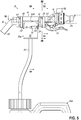
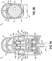
- FIG. 5 illustrates the portable chemical dispenser 10 coupled to the first chemical source 50a via cartridge 70a and conduit line 84 but with the handle 12 being shown in the second position with the actuator 34 in a downturned position (e.g., low flow).
- the handle 12 when the handle 12 is in the second position, the outlet 32 of the valve housing 12 is aligned with the second eductor 42b of the eductor housing 14.
- the diluent valve 24 When an operator presses the lever 34, the diluent valve 24 is moved to the opened position and diluent flows through the valve housing 12, out of the outlet 32, and into the passageway 46b of eductor 42b.
- This diluent flow through eductor 42b creates a vacuum that causes the poppet valve 88 in passageway 74b in the cartridge 70a to open and allow chemical from the chemical source 50a to be drawn into the passageway 74b in the cartridge 70a, into the passageway 54b in the chemical inlet port 52, and into the eductor 42b via the opening 48b.
- the metering tip in the passageway 74b of cartridge 70a meters the amount of chemical that is drawn so as to arrive at the desired dilution ratio.
- the portable chemical dispenser 10 may be disconnected from the first chemical source 50a by disengaging the cartridge 70a from the chemical inlet port 52 of the portable chemical dispenser 10 (e.g., the bayonet connection).
- the cartridge 70b associated with the second chemical source 50b may be connected to the chemical inlet port 52 of the portable chemical dispenser 10 via the bayonet connection as described above.
- the particular eductor 42a, 42b may then be selected (e.g., high flow rate or low flow rate) for dispensing the second chemical by moving the handle 12 to one of the first or second positions (see Figs. 4C or 5C ).
- the operator may then engage the actuator 34 (e.g., press/pull the lever) to open the diluent valve 24 and dispense the chemical solution to a receptacle.
- the metering tips in the cartridge 70b set the dilution ratio for the second chemical, which may be different from the dilution ratio for the first chemical. This process may be repeated for additional chemicals being dispensed by the portable chemical dispenser 10.
- the portable chemical dispenser 10 described above provides a number of advantages over current portable chemical dispensers.
- the portable chemical dispenser 10 may be used to dispense multiple chemicals from different chemical sources 50, with each chemical potentially having a different dilution ratio. This is primarily achieved by associating the metering element(s) responsible for metering the dosing of the chemical in the diluent flow with the chemical source instead of the portable chemical dispenser itself, as is done in conventional portable chemical dispensers.
- each chemical source includes a dedicated cartridge configured to be easily and selectively coupled to the portable chemical dispenser. The cartridge contains the metering elements that control the dosing of the chemical and the dilution ratio of the resulting chemical solution.
- the portable chemical dispenser 10 includes a plurality of eductors 42, and the handle 12 of the portable chemical dispenser 10 is rotatable about the longitudinal axis of the portable chemical dispenser 10 as a means to select one of the plurality of eductors 42.
- the portable chemical dispenser 10 may be configured to provide a high-flow dispensing process and a low-flow dispensing process.
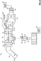
- Figs. 6-8 illustrate another embodiment of a portable chemical dispenser 110 in accordance with aspects of the invention.
- the portable chemical dispenser 110 is similar to chemical dispenser 10 described in detail above and only the differences between the dispensers will be described in any detail. Elements of the portable chemical dispenser 110 that are similar to elements of portable chemical dispenser 10 have a similar reference number but are preceded by a "1".
- the primary difference between portable chemical dispensers 10 and 110 is in the construction of the eductor housing. More particularly, the eductor housing 114 of the portable chemical dispenser 110 includes only a single eductor 142 and not multiple eductors as provided by eductor housing 14 in portable chemical dispenser 10. Thus, when the diluent valve 124 is in the opened position, all the diluent flows through the single eductor 142 to draw chemical in from chemical source 150 and provide a chemical solution at a single flow rate, e.g., at a medium flow rate (e.g., 2 gallons/minute) somewhere between the high and low flow rates described above.
- the construction and operation of the portable chemical dispenser 110 is for all intents and purposes the same as that described above. Accordingly, one of ordinary skill in the art will understand the portable chemical dispenser 110 based on the description above and a further description will not be provided.
- the valve housing 112 may remain rotatable relative to the eductor housing 114 such that the "handle" 112 may be rotatable about the longitudinal axis of the dispenser and allow an operator to press or pull the actuator 134 to dispense the chemical solution. It should be understood, however, that rotating the handle does not alter which eductor 142 the diluent flows through since the portable chemical dispenser 110 has but one eductor 142.
- the valve housing 112 may be fixed relative to the eductor housing 114 such that, for example, the actuator 134 is in an upright position (as shown) or a downturned position (not shown) in accordance with the preference of the operator.
- the portable chemical dispenser 110 may first be used to dispense a first chemical from a first chemical source 150a, then be used to dispense a second chemical from a second chemical source 150b. Again, this is primarily achieved by providing cartridges 170a, 170b having the metering elements that control the dosing of the chemical and the dilution ratio of the resulting chemical solution.
- the cartridges 170a, 170b are configured to easily and selectively couple to the chemical inlet port 152 of the portable chemical dispenser 110 to place the chemical source 150 in communication with the eductor 142.
- janitorial service provides do not have to purchase many portable chemical dispensers, such as one portable chemical dispenser for each chemical across the janitorial platform. Instead, janitorial service provides may only provide a single portable chemical dispenser that may be readily used to dispense multiple chemicals across the janitorial platform. Accordingly, the portable chemical dispenser 110 according to the present disclosure provides a more efficient, lower cost solution for janitorial service providers.
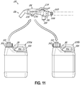
- Figs. 9-11 illustrate another embodiment of a portable chemical dispenser 210 in accordance with aspects of the invention.
- the portable chemical dispenser 210 is similar to chemical dispenser 10 described in detail above and only the differences between the dispensers will be described in any detail. Elements of the portable chemical dispenser 210 that are similar to elements of portable chemical dispenser 10 have a similar reference number but are preceded by a "2".
- portable chemical dispenser 210 may include only a single eductor 242 and not multiple eductors as provided by eductor housing 14 in portable chemical dispenser 10. That difference was described above and will not be repeated here.
- Another difference between portable chemical dispensers 10 and 210 is in the manner in which the dispenser is operatively coupled to a chemical source.
- the portable chemical dispenser 10 included a chemical inlet port 52 that is configured to couple to a cartridge 70 associated with the chemical source 50 through, for example, the bayonet connection.
- the cartridge 70 is in turn coupled to the chemical source 50 via a length of conduit or tubing 84.
- an operator may hold the portable chemical dispenser 10 in one hand and hold the chemical source 50 in the other hand.
- the portable chemical dispenser 10 and the chemical source 50 may be separated over some distance, which is traversed by a length of tubing 84 (e.g., about three feet in length).
- the portable chemical dispenser 210 is configured to operate in a slightly different way. More particularly, the portable chemical dispenser 210 is configured to couple directly to an outlet port 300 on the chemical source 250.
- the outlet port 300 may be associated with a cap 302 of the chemical source 250.
- the chemical inlet port 252 of the portable chemical dispenser 210 may be slightly different than that described above.
- the chemical inlet port 252 may include a male connector and the outlet port 300 on the chemical source 250 may include a female connector such that upon connecting the portable chemical dispenser 210 to the chemical source 250, the eductor 242 of the portable chemical dispenser 210 is in fluid communication with the chemical stored in the chemical source 250.
- the bayonet connection is omitted and the chemical inlet port 252 forms a fluid-tight connection with the outlet port 300 of the chemical source 300 through a slip fit.
- the portable chemical dispenser 210 is configured to be secured to the chemical source 250 such that the assembly of the portable chemical dispenser 210 and the chemical source 250 may be carried by one hand of an operator.
- the valve housing 212 may include a clip arm 304 projecting from the valve housing 212 that is configured to engage an arm receiver 306 on the chemical source 250 for securing the portable chemical dispenser 210 and the chemical source 250 together.
- the clip arm 304 may include an L-shaped bracket that projects from a lower side of the valve housing 212 (e.g., opposite to the actuator 234) and then extends to one side of the valve housing 214.
- the chemical source 250 may include a handle 308 defining an opening 310 that operates as the arm receiver 306.
- the portable chemical dispenser 210 is configured to clip to the handle 308 of the chemical source 250.
- the portable chemical dispenser 210 is configured to be coupled directly to the chemical source 250, the location of the metering elements that control the dosing of the chemical with the diluent has changed. For example, a separate cartridge 70 spaced from the chemical source 50 is omitted in this embodiment. Instead, the metering and valve elements that had previously been included in the cartridge 70 are now positioned either in the cap 302 of the chemical source 250 or in the confines of the chemical source 250 itself, such as in a neck portion of the chemical source 250, for example. In any event, the construction and operation of the portable chemical dispenser 210 is similar to that described above and one of ordinary skill in the art will understand the construction and operation of the portable chemical dispenser 210 based on the description above.
- the portable chemical dispenser 210 may first be used to dispense a first chemical from a first chemical source 250a, then be used to dispense a second chemical from a second chemical source 250b. Again, this is primarily achieved by associating the metering elements that control the dosing of the chemical and the dilution ratio of the resulting chemical solution with the chemical sources 250a, 250b and not the portable chemical dispenser itself.
- janitorial service provides do not have to purchase many portable chemical dispensers, such as one portable chemical dispenser for each chemical across the janitorial platform. Instead, janitorial service provides may only provide a single portable chemical dispenser that may be readily used to dispense multiple chemicals across the janitorial platform. Accordingly, the portable chemical dispenser 210 according to the present disclosure provides a more efficient, lower cost solution for janitorial service providers.
- valve and metering elements for controlling the dosing of the chemical with the diluent were located within the cap 302 and/or within the neck of the chemical source 250.
- the cartridges 70, 170 may be omitted and the valve and metering elements located within the cap and/or within the neck of the chemical sources 50, 150. Such embodiments remain within the scope of the present invention.
- the nozzle of the portable chemical dispenser may be configured as an endpiece configured to couple to various nozzles.
- the endpiece may be configured to couple to a foam applicator or a spray applicator for applying a chemical solution to various surfaces, such as walls, floors and/or ceilings.
Landscapes
- Engineering & Computer Science (AREA)
- Mechanical Engineering (AREA)
- Chemical & Material Sciences (AREA)
- Chemical Kinetics & Catalysis (AREA)
- Feeding, Discharge, Calcimining, Fusing, And Gas-Generation Devices (AREA)
Abstract
A portable chemical dispenser (10) for dispensing a chemical with a diluent includes a valve housing (12) having a valve with an opened position and a closed position, an eductor housing (14) coupled to the valve housing and including one or more eductors (42), and a nozzle (16) coupled to the eductor housing (14) and configured to direct the flow of a chemical solution to a receptacle, wherein the joint between the valve housing (12) and the eductor housing (14) permits relative rotations between the two housings (12, 14). The portable chemical dispenser (10) may also be devoid of metering elements that control the dosing of the chemical. A method of using the portable chemical dispenser (10) is also disclosed.
Description
- This invention generally relates to an improved portable chemical dispenser for dispensing one or more chemicals, and more particularly to a portable chemical dispenser usable with multiple chemical sources across an application platform, such as a janitorial platform, and to a method of using such a portable chemical dispenser.
- The dispensing of liquid chemical products from one or more chemical sources or reservoirs is a common requirement of many industries, such as the laundry, textile, warewash, healthcare, janitorial services and food processing industries. In the janitorial services industry, for example, many applications require aqueous solutions with various chemical agents for cleaning and sanitizing purposes. Chemical dispensing systems have been developed to deliver chemical products or chemical solutions for such applications. By way of example, many chemical dispensing systems used in janitorial applications rely on eductors for drawing chemical products into a diluent stream to produce a chemical solution containing the chemical product at a desired dilution ratio.
- Eductors are devices that pass a liquid through a choke to generate the Venturi effect. The suction generated by the Venturi effect is used to draw another liquid into the eductor. For example, water running through the eductor may cause a chemical product to be drawn into the eductor, where it mixes with the water and is subsequently discharged as a dilute chemical solution. Eductors are considered attractive because they do not require external power to mix the chemical products with a diluent source (in contrast to, for example, a pump). Instead, the energy of the diluent stream is used to "pump" the chemical product into the diluent stream. Eductors are often used to mix chemical products with water in dispensing systems to produce small batches of chemical solutions for use in industrial applications. These batches of chemical solutions may be discharged into various point-of-use receptacles for use in a desired manner. By way of example, in janitorial applications chemical solutions may be discharged into various cleaning receptacles, such as spray bottles or mop buckets. To this end, some chemical dispensers may have a low-flow setting for spray bottle dispensing and a high-flow setting for bucket or large receptacle dispensing.
- In some janitorial applications, the chemical dispensing system includes a relatively small, portable, eductor-based dispenser operatively coupled to a diluent source (e.g., a water source) and also operatively coupled to a reservoir of chemical. The reservoir of chemical may be a relatively small (e.g., one gallon), portable container of chemical that is coupled to the chemical dispenser via a length of tubing that allows the chemical to be drawn into the chemical dispenser with the movement of diluent through the eductor. Janitorial applications typically include the dispensing a multiple chemicals (e.g., cleaning agent, sanitizing agent, etc.) into different receptables. Additionally, the dilution ratio of the chemical with diluent varies depending on the particular chemical that is being dispensed. The dilution ratio is typically controlled by a metering tip associated with the chemical dispenser and ranges anywhere between about 10:1 to about 128:1 (e.g., about 64:1). Thus, a first cleaning agent may be diluted at a first ratio, a second cleaning agent may be diluted at a second ratio; a first sanitizing agent may be diluted at a third ratio, etc. all at different dilution ratios. For a given eductor size and construction, and thus a fixed vacuum potential from the eductor, the amount of chemical being drawn into the eductor may be varied by positioning a metering tip in the chemical flow path. The metering tip may be selected to provide the desired dilution ratio for the resulting chemical solution.
- As a result, the chemical dispenser used to dispense a particular chemical becomes specific to that chemical and generally cannot be used to dispense other desired chemicals in janitorial applications. In other words, each chemical used in janitorial applications typically has its own chemical dispenser for dispensing that chemical at the recommended dilution ratio. Such an arrangement is inefficient and increases the cost to janitorial service providers. Accordingly, there is a need for a small, low-cost portable chemical dispenser that is capable of dispensing multiple chemicals across the janitorial platform and at different dilution ratios in accordance with the recommended dosing.
- A portable chemical dispenser for dispensing a chemical with a diluent is disclosed. The portable chemical dispenser includes a valve housing having a diluent valve with an opened position and a closed position, wherein diluent is configured to flow through the portable chemical dispenser when the diluent valve is in the opened position and diluent is prevented from flowing through the portable chemical dispenser when the diluent valve is in the closed position. The portable chemical dispenser further includes an eductor housing coupled to the valve housing and including one or more eductors, wherein the eductor housing includes a chemical inlet port configured to be coupled to a chemical source storing the chemical, and a nozzle coupled to the eductor housing and configured to direct the flow of a chemical solution to a receptacle. The joint between the valve housing and the eductor housing permits relative rotations between the two housings. The portable chemical dispenser may also be devoid of metering elements that control the dosing of the chemical with the diluent.
- The eductor housing may include a plurality of eductors and rotations of the valve housing relative to the eductor housing may place the diluent flow in communication with different eductors in the eductor housing when the diluent valve is in the opened position. In one embodiment, for example, the eductor housing includes first and second eductors and the valve housing is rotatable relative to the eductor housing between a first position wherein the diluent is configured to be in fluid communication with a first eductor, and a second position wherein the diluent is configured to be in fluid communication with the second eductor. In one embodiment, the valve housing may include an actuator, wherein the actuator is in a first position in the first position of the valve housing and the actuator is in a second position in the second position of the valve housing. The first and second positions of the valve housing relative to the eductor housing may be offset by 180 degrees.
- A method of dispensing a plurality of chemicals from respective chemical sources using a diluent including providing a portable chemical dispenser is disclosed. The portable chemical dispenser may be devoid of any metering elements that control the dosing of the chemical with the diluent. The method may include connecting the portable chemical dispenser with a first chemical source storing a first chemical; dispensing the first chemical using the portable chemical dispenser; disconnecting the portable chemical dispenser from the first chemical source; connecting the portable chemical dispenser with a second chemical source storing a second chemical; and dispensing the second chemical using the portable chemical dispenser. The first and second chemicals may be dispensed at the same or different dilution ratios. Additionally, the first and second chemicals may be dispensed at two different flow rates by the portable chemical dispenser.
- In one embodiment, connecting the portable chemical dispenser with the first chemical source further includes connecting the portable chemical dispenser with a first cartridge associated with the first chemical source, wherein the first cartridge contains metering elements that control the dosing of the first chemical with the diluent. The first cartridge may be separated from the first chemical source and operatively coupled to the first chemical source by a tube, preferably a single tube. In one embodiment, the first cartridge may be positioned within a cap or within the confines of the first chemical source. In one embodiment, the portable chemical dispenser may be clipped to the first chemical source.
- In one embodiment, connecting the portable chemical dispenser with the second chemical source includes connecting the portable chemical dispenser with a second cartridge associated with the second chemical source, wherein the second cartridge contains metering elements that control the dosing of the second chemical with the diluent. The second cartridge may be separated from the second chemical source and operatively coupled to the second chemical source by tubing. In one embodiment, the second cartridge may be positioned within a cap or within the confines of the second chemical source. In one embodiment, the portable chemical dispenser may be clipped to the second chemical source.
- The accompanying drawings, which are incorporated in and constitute a part of this specification, illustrate embodiments of the invention and, together with a general description of the invention given above, and the detailed description given below, serve to explain the invention.
-
Fig. 1 illustrates a perspective view of a portable chemical dispenser in accordance with a first embodiment of the invention; -
Fig. 2 illustrates the portable chemical dispenser ofFig. 1 with a cartridge associated with a chemical source; -
Fig. 3 illustrates the portable chemical dispenser ofFig. 1 being connectable to a plurality of chemical sources; -
Fig. 4 illustrates the portable chemical dispenser ofFig. 1 coupled to a first chemical source and dispensing through a first eductor of the portable chemical dispenser; -
Fig. 4A is a cross-sectional view through the portable dispenser shown inFig. 4 generally alongline 4A-4A; -
Fig. 4B is a cross-sectional view through the portable dispenser shown inFig. 4 generally alongline 4B-4B; -
Fig. 4C is a cross-sectional view through the portable dispenser shown inFig. 4 generally alongline 4C-4C; -
Fig. 4D is a partial cross-sectional view through the portable dispenser shown inFig. 4 generally alongline 4D-4D; -
Fig. 5 illustrates the portable chemical dispenser ofFig. 1 coupled to a first chemical source and dispensing through a second eductor of the portable chemical dispenser; -
Fig. 5A is a cross-sectional view through the portable dispenser shown inFig. 5 generally alongline 5A-5A; -
Fig. 5B is a cross-sectional view through the portable dispenser shown inFig. 5 generally alongline 5B-5B; -
Fig. 5C is a cross-sectional view through the portable dispenser shown inFig. 5 generally alongline 5C-5C; -
Fig. 5D is a partial cross-sectional view through the portable dispenser shown inFig. 5 generally alongline 5D-5D; -
Fig. 6 illustrates a side view of a portable chemical dispenser in accordance with another embodiment of the invention; -
Fig. 7 illustrates the portable chemical dispenser ofFig. 6 with a cartridge associated with a chemical source; -
Fig. 8 illustrates the portable chemical dispenser ofFig. 6 being connectable to a plurality of chemical sources; -
Fig. 9 illustrates a perspective view of a portable chemical dispenser in accordance with another embodiment of the invention; -
Fig. 10 illustrates the portable chemical dispenser ofFig. 9 connected to a chemical source; and -
Fig. 11 illustrates the portable chemical dispenser ofFig. 6 being connectable to a plurality of chemical sources. -
Fig. 1 illustrates aportable chemical dispenser 10 in accordance with a first embodiment of the invention. As illustrated in this figure and the following figures, theportable chemical dispenser 10 generally includes avalve housing 12 at a first end of theportable chemical dispenser 10, anintermediate educator housing 14, and anozzle 16 at a second end of theportable chemical dispenser 10. Thevalve housing 12, in addition to providing the diluent to theportable chemical dispenser 10, may operate as a "handle" for theportable chemical dispenser 10, such as by an operator. As such, the term valve housing and handle may be used interchangeably herein. Theeductor housing 14 includes one or more eductors that provide for the introduction of a chemical into theportable chemical dispenser 10. Lastly, thenozzle 16 provides a flow path for delivering the chemical solution (i.e., chemical and diluent mixed together) to a desired receptacle, such as a spray bottle, mop bucket or the like. A description of each of these components will now be provided. - The
valve housing 12 includes afirst end 18 configured to be coupled to adiluent source 20, asecond end 22 configured to be coupled to theeductor housing 14, and adiluent valve 24 disposed between the first and second ends 18, 22. Thefirst end 18 may include afluid connector 26 configured to couple to afluid conduit 28 that supplies the diluent fromdiluent source 20 under pressure. For example, thediluent source 20 may be a municipal water supply. In one embodiment, thefluid connector 26 may be designed to rotate or swivel relative to the remainder of thevalve housing 12 to provide a greater level of movement to thefluid conduit 28 and/orportable chemical dispenser 10 during use. - The
second end 22 of thevalve housing 12 includes a snap-fit connection for coupling to theeductor housing 14. By way of example and without limitation, in an exemplary embodiment the snap-fit connection may include one or more detents 30 (e.g., an annular rib) configured to cooperate with one or more features on theeductor housing 14 for connecting thevalve housing 12 andeductor housing 14 together. Thesecond end 22 of thevalve housing 12 may also include one or more seals for connecting to theeductor housing 14 in a fluid-tight manner. - The
diluent valve 24 of thevalve housing 12 includes an opened position and a closed position. In the opened position of thediluent valve 24, diluent (e.g., water) may pass through thevalve housing 12 and flow into theeductor housing 14 via an off-center outlet 32 on the downstream side of the diluent valve 24 (seeFigs. 4B and5B ), and in the closed position of thediluent valve 24, diluent is not permitted to flow through thevalve housing 12. Thediluent valve 24 may include anactuator 34 for moving thediluent valve 24 between the opened and closed positions. In an exemplary embodiment, theactuator 34 may include a pivotable lever having a first position when thediluent valve 24 is in the closed position and a second position when thediluent valve 24 is in the opened position. When chemical dispensing is desired, an operator may press the lever to thereby position thediluent valve 24 in the opened position and thereby allow diluent to flow through thevalve housing 12 and into theeductor housing 14. Thediluent valve 24 may be spring biased such that upon release of the lever, thediluent valve 24 returns to its normally closed position and diluent is not permitted to flow through thevalve housing 12.Diluent valve 24 is of the type that is generally known in the art, and thus a detailed description of the construction and operation of thediluent valve 24 will be omitted for sake of brevity. In one embodiment, thediluent valve 24 may include a latch mechanism for maintaining thediluent valve 24 in the opened position one positioned in the opened position by an operator. For example, theactuator 34 may include a latch mechanism for maintaining the lever in a depressed state. Although not shown, the latch mechanism may include opposing fingers configured to selectively engage one another, such as by a button or slide switch, to keep the lever in the depressed state (and thediluent valve 24 in the opened position). Upon release of the latch mechanism, theactuator 20 will move to the closed position. - The
eductor housing 16 includes afirst end 38 configured to be coupled to thevalve housing 12, asecond end 40 configured to be coupled to thenozzle 16, and one or more eductors 42 disposed between the first and second ends 38, 40. In an exemplary embodiment, theeductor housing 16 may include twoeductors 42a, 42b, however theeducator housing 14 may include more or less eductors. As discussed above, thefirst end 38 of theeductor housing 14 is configured to couple to thesecond end 22 of thevalve housing 12 through a snap-fit connection. To this end, thesecond end 22 of thevalve housing 12 includes one ormore detents 30 and thefirst end 38 of theeductor housing 14 is configured to include one or more catches 44 (e.g., in the form of triangular-shaped ramps). When the ends 22, 38 are brought together, the one ormore detents 30 engage the one ormore catches 44 and cause the one ormore detents 30 to elastically flex or deform so as to allow the one ormore detents 30 to pass by or beyond the one or more catches 44. Once the one ormore detents 30 pass by the one ormore catches 44, thedetents 30 spring back to a non-deformed position or less deformed position and thereby lock the one ormore detents 30 behind the one ormore catches 44 to secure thevalve housing 12 and theeducator housing 14 together. This snap-fit connection prevents any significant relative axial movements between theeductor housing 14 and thevalve housing 12. - In one aspect of the invention, however, the snap-fit connection between the
valve housing 12 and theeductor housing 14 is configured to permit relative rotations between thevalve housing 12 and theeductor housing 14. Thus, while relative axial movements between thevalve housing 12 and theeductor housing 14 along the longitudinal axis of thechemical dispenser 10 are prevented, relative rotational movements about the longitudinal axis of theportable chemical dispenser 10 are permitted. The purpose of this feature will be explained in more detail below. In any event, it should be recognized that through this snap-fit connection, the handle of theportable chemical dispenser 10 may rotate about the longitudinal axis of thedispenser 10 relative to the remainder portions of theportable chemical dispenser 10. - The
second end 40 of theeductor housing 14 includes a snap-fit connection for coupling to thenozzle 16. By way of example and without limitation, in an exemplary embodiment the snap-fit connection may include one or more detents 64 (e.g., an annular rib) configured to cooperate with one or more features on thenozzle 16 for connecting theeductor housing 14 andnozzle 16 together. Thesecond end 40 of theeductor housing 14 may also include one or more seals for connecting to thenozzle 16 in a fluid-tight manner. - The
eductors 42a, 42b of theeductor housing 14 are of conventional design and include converging-divergingpassages 46a, 46b having a throat or choke region. The throat region of each of thepassages 46a, 46b includes respective openings 48a, 48b in communication with achemical source 50 for introducing a chemical stored in thechemical source 50 into the diluent stream flowing through a select one of theeductors 42a, 42b. More particularly, theeductor housing 14 includes achemical inlet port 52 depending from theeductor housing 14 adjacent the throat region to facilitate a connection to thechemical source 50. As illustrated inFigs. 4A and5A , thechemical inlet port 52 includes twopassageways passageways 46a, 46b and in fluid communication with theirrespective passageways 46a, 46b via openings 48a, 48b (seeFigs. 4D and5D ). The connection between thechemical inlet port 52 and thechemical source 50 will be described in more detail below. Eductors of this type are generally well known in the art, and thus a further detailed discussion of theeductors 42a, 42b and their operation will be omitted for sake of brevity. - The
nozzle 16 includes afirst end 58 configured to be coupled to theeductor housing 14, asecond end 60 configured to be in fluid communication with a receptacle, and apassageway 62 extending between the first and second ends 58, 60. As discussed above, thefirst end 58 of thenozzle 16 is configured to couple to thesecond end 40 of theeductor housing 14 through a snap-fit connection. To this end, thesecond end 40 of theeductor housing 14 includes one ormore detents 64 and thefirst end 58 of thenozzle 16 is configured to include one or more catches 66 (e.g., in the form of triangular-shaped ramps). When the ends 40, 58 are brought together, the one ormore detents 64 engage the one ormore catches 66 and cause the one ormore detents 64 to elastically flex or deform so as to allow the one ormore detents 64 to pass by or beyond the one or more catches 66. Once the one ormore detents 64 pass by the one ormore catches 66, thedetents 64 spring back to a non-deformed position or less deformed position and thereby lock the one ormore detents 64 behind the one ormore catches 66 to secure theeducator housing 14 and thenozzle 16 together. - This snap-fit connection prevents any significant relative axial movements between the
nozzle 16 and theeductor housing 14. Similar to the above, in one embodiment, the snap-fit connection between theeductor housing 14 and thenozzle 16 is configured to permit relative rotations between theeductor housing 14 andnozzle 16. Thus, while relative axial movements between theeductor housing 14 andnozzle 16 along the longitudinal axis of theportable chemical dispenser 10 are prevented, relative rotational movements about the longitudinal axis of theportable chemical dispenser 10 are permitted. This may facilitate improved dispensing of chemical solutions from theportable chemical dispenser 10. In an alternative embodiment, theeducator housing 14 and thenozzle 16 may be rotationally fixed relative to each other. Thenozzle 16 may include one or more clips (not shown) for securing thenozzle 16 to the receptacle in which the chemical solution is being dispensed. For example, thenozzle 16 may include a clip for securing thenozzle 16 to a bucket. - In one aspect of the invention and as illustrated in
Figs. 2 and3 , theportable chemical dispenser 10 is configured to be used for dispensing multiple chemicals from multiplechemical sources 50 and is not limited for use with one specific chemical or chemical source, as with prior portable chemical dispensers. By way of example, as illustrated inFig. 3 , theportable chemical dispenser 10 is configured to be operatively coupled to a firstchemical source 50a for dispensing a first chemical and is further configured to be coupled to a secondchemical source 50b for dispensing a second chemical. It should be recognized that thechemical dispenser 10 may be used to dispense additional chemicals from furtherchemical sources 50. For example, thechemical dispenser 10 may be configured to dispense most, if not all, of the chemicals used across an application platform, such as a janitorial platform. Thus, theportable chemical dispenser 10 may be used to dispense multiple chemicals even when the dilution ratios of the multiple chemicals are different from one another. The inability of prior chemical dispensers to accommodate different dilution ratios for different chemicals is a primary factor for why portable chemical dispensers were limited for use with a specific chemical or chemical source. - That limitation has been overcome in accordance with aspects of the present invention. More particularly, in accordance with aspects of the present invention, the metering elements that control the dilution ratio in a chemical solution have been physically separated from the
portable chemical dispenser 10 and instead are associated with theparticular chemical source 50. In this regard and in an exemplary embodiment, eachchemical source 50 may include acartridge 70 that includes various metering elements which control the amount of chemical that is drawn into theportable chemical dispenser 10 from thechemical source 50 when thechemical source 50 is operatively coupled to the portable chemical dispenser 10 (and subject to the Venturi effect). Thus, when a first chemical is to be dispensed, theportable chemical dispenser 10 may be coupled to afirst cartridge 70a associated with the firstchemical source 50a. Thefirst cartridge 70a controls the amount of the first chemical being drawn into theportable chemical dispenser 10 for providing the desired dilution ratio for the first chemical. Subsequently, theportable chemical dispenser 10 may be disconnected from thefirst cartridge 70a and connected to asecond cartridge 70b associated with the secondchemical source 50b. Thesecond cartridge 70b controls the amount of the second chemical being drawn into theportable chemical dispenser 10 for providing the desired dilution ratio for the second chemical. Theportable chemical dispenser 10 may be disconnected from thesecond cartridge 70b and connected to further cartridges for dispensing additional chemicals at potentially different dilution ratios, as dictated by theirrespective cartridges 70. - By way of example and without limitation, in an exemplary embodiment the
cartridge 70 may include a generallycylindrical housing 72 defining first andsecond passageways passageways respective passageways chemical inlet port 52 of theportable chemical dispenser 10 when thecartridge 70 is coupled thereto. Asecond end 78 of thepassageways connector 82. Theconnector 82 is configured to receive a conduit line 84 (e.g., flexible tubing) operatively coupled to thechemical source 50. In an exemplary embodiment, eachpassageway metering tip region 86a, 86b for receiving a metering tip that is configured to dispense a specific amount of chemical when subject to operation of its associatedeductor 42a, 42b. Metering tips of the type used herein are generally known in the art and a further description of the metering tips will not be provided. Eachpassageway poppet valve 88 for closing off access to thechemical source 50 upon deactivation of its associatedeductor 42a, 42b or disconnection of thecartridge 70 from theportable chemical dispenser 10.Poppet valves 88 of the type used herein are generally known in the art and a further description of the poppet valves will not be provided. Although not shown, thecartridge 70 may include a fastener, such as a hook or eyelet, for securing thecartridge 70 at a height above thechemical source 50, such as in a storage cabinet or the like. This would prevent chemical from thechemical source 50 from leaking out in the event that thepoppet valves 88 in the cartridge would fail. - The
cartridges 70 associated with thechemical sources 50 are configured to be easily and selectively connected/disconnected from theportable chemical dispenser 10. In an exemplary embodiment, acartridge 70 may be coupled to theportable chemical dispenser 10, and more particularly to thechemical inlet port 52 through a bayonet connection. For example, thechemical inlet port 52 may include one or more detents 90 (e.g., two detents) and thecartridge 70 may include one ormore slots 92. A first end of the one ormore slots 92 includes akeyway 94 for allowing arespective detent 90 to pass into the one ormore slots 92. Once the one ormore detents 90 are positioned in the one ormore slots 92, thecartridge 70 may be turned or rotated such that the one ormore detents 90 traverse the one ormore slots 92 until a second closed end of the one ormore slots 92 is reached. The one ormore slots 92 may be slightly angled so as to bring thecartridge 70 into tight engagement with thechemical inlet port 52, thereby forming a fluid-tight seal therebetween. To disconnect thecartridge 70 from theportable chemical dispenser 10, thecartridge 70 may be rotated in the opposite direction until the one ormore detents 90 align with the one ormore keyways 94, thereby allowing thecartridge 70 to move away from theportable chemical dispenser 10. - Operation of the
portable chemical dispenser 10 will now be described in detail. When it is desired to dispense a first chemical, theportable chemical dispenser 10 may be coupled to the firstchemical source 50a that holds a supply of the first chemical. In this regard, thecartridge 70a associated with the firstchemical source 50a may be coupled to thechemical inlet port 52 of theportable chemical dispenser 10 through the bayonet connection. Theportable chemical dispenser 10 may also be coupled to thediluent source 20. At this point, theportable chemical dispenser 10 is ready to dispense the first chemical. - As discussed above, the
portable chemical dispenser 10 includes twoeductors 42a, 42b that may have two different flow rates associated with theeductors 42a, 42b (e.g., high flow and low flow). Thus, theportable chemical dispenser 10 must be configured to dispense from a select one of theeductors 42a, 42b depending on, for example, the receptacle into which the chemical solution is being dispensed. In one aspect of the invention, thevalve housing 12, which operates as a handle for the portable chemical dispenser 10 (and the term handle may be used interchangeably with the term valve housing) is rotatable relative to the remainder of theportable chemical dispenser 10 between a first position and a second position. In the first position, theoutlet 32 of thevalve housing 12 is in fluid communication with the first eductor 42a (e.g., high flow; 3 gallons per minute), and in the second position, theoutlet 32 of thevalve housing 12 is in fluid communication with thesecond eductor 42b (e.g., low flow; 1 gallon per minute). By way of example, in one embodiment the first and second positions may be offset by about 180 degrees. Thus, in the first position of thehandle 12, the actuator 34 (e.g., lever) may be positioned on top of theportable chemical dispenser 10 such that pressing downwardly will move thediluent valve 24 to the opened position and allow diluent to pass into the first eductor 42a. In the second position of thehandle 12, theactuator 34 may be positioned below theportable chemical dispenser 10 such that pulling upwardly will move thediluent valve 24 to the opened position and allow diluent to pass into thesecond educator 42b. - In one embodiment, the
portable chemical dispenser 10 may include a rotational limit mechanism that limits the relative rotation between thevalve housing 12 and theeductor housing 14. In this regard, thevalve housing 12 may include atab 96 and theeductor housing 14 may include a cutout orslot 98 which receives the tab when thevalve housing 12 andeductor housing 14 are coupled together (Fig. 1 ). Thetab 96 is configured to engage against a first end wall of theslot 98 when thehandle 12 is in the first position (Fig. 4C ) and configured to engage against a second end wall of theslot 98 when in the second position (Fig. 5C ). Thetab 96 is configured to traverse theslot 98 as thehandle 12 is moved between the first and second positions. -
Fig. 4 illustrates theportable chemical dispenser 10 coupled to a firstchemical source 50a viacartridge 70a andconduit line 84. InFig. 4 , thehandle 12 is shown in the first position with theactuator 34 in an upright position (e.g., high flow). As illustrated inFigs. 4A-4D , when thehandle 12 is in the first position, theoutlet 32 of thevalve housing 12 is aligned with the first eductor 42a of theeductor housing 14. When an operator presses thelever 34, thediluent valve 24 is moved to the opened position and diluent flows through thevalve housing 12, out of theoutlet 32, and into thepassageway 46a of eductor 42a. This diluent flow through eductor 42a creates a vacuum that causes thepoppet valve 88 inpassageway 74a in thecartridge 70a to open and allow chemical from thechemical source 50a to be drawn into thepassageway 74a in thecartridge 70a, into thepassageway 54a in thechemical inlet port 52, and into the eductor 42a via the opening 48a. The metering tip in thepassageway 74a ofcartridge 70a meters the amount of chemical that is drawn so as to arrive at the desired dilution ratio. Upon release of theactuator 34 by the operator, thediluent valve 24 moves to the closed position, the diluent flow through the eductor 42a ceases, and thepoppet valve 88 inpassageway 74a of thecartridge 70a closes. - In a similar manner,
Fig. 5 illustrates theportable chemical dispenser 10 coupled to the firstchemical source 50a viacartridge 70a andconduit line 84 but with thehandle 12 being shown in the second position with theactuator 34 in a downturned position (e.g., low flow). As illustrated inFigs. 5A-5D , when thehandle 12 is in the second position, theoutlet 32 of thevalve housing 12 is aligned with thesecond eductor 42b of theeductor housing 14. When an operator presses thelever 34, thediluent valve 24 is moved to the opened position and diluent flows through thevalve housing 12, out of theoutlet 32, and into the passageway 46b ofeductor 42b. This diluent flow througheductor 42b creates a vacuum that causes thepoppet valve 88 inpassageway 74b in thecartridge 70a to open and allow chemical from thechemical source 50a to be drawn into thepassageway 74b in thecartridge 70a, into thepassageway 54b in thechemical inlet port 52, and into the eductor 42b via the opening 48b. The metering tip in thepassageway 74b ofcartridge 70a meters the amount of chemical that is drawn so as to arrive at the desired dilution ratio. Upon release of theactuator 34 by the operator, thediluent valve 24 moves to the closed position, the diluent flow through theeducator 42b ceases and thepoppet valve 88 inpassageway 74b of thecartridge 70b closes. - Upon completion of dispensing the first chemical from the first
chemical source 50a, theportable chemical dispenser 10 may be disconnected from the firstchemical source 50a by disengaging thecartridge 70a from thechemical inlet port 52 of the portable chemical dispenser 10 (e.g., the bayonet connection). When it is desired to dispense a second chemical from a secondchemical source 50b, thecartridge 70b associated with the secondchemical source 50b may be connected to thechemical inlet port 52 of theportable chemical dispenser 10 via the bayonet connection as described above. Theparticular eductor 42a, 42b may then be selected (e.g., high flow rate or low flow rate) for dispensing the second chemical by moving thehandle 12 to one of the first or second positions (seeFigs. 4C or5C ). The operator may then engage the actuator 34 (e.g., press/pull the lever) to open thediluent valve 24 and dispense the chemical solution to a receptacle. The metering tips in thecartridge 70b set the dilution ratio for the second chemical, which may be different from the dilution ratio for the first chemical. This process may be repeated for additional chemicals being dispensed by theportable chemical dispenser 10. - The
portable chemical dispenser 10 described above provides a number of advantages over current portable chemical dispensers. First, theportable chemical dispenser 10 may be used to dispense multiple chemicals from differentchemical sources 50, with each chemical potentially having a different dilution ratio. This is primarily achieved by associating the metering element(s) responsible for metering the dosing of the chemical in the diluent flow with the chemical source instead of the portable chemical dispenser itself, as is done in conventional portable chemical dispensers. More particularly, each chemical source includes a dedicated cartridge configured to be easily and selectively coupled to the portable chemical dispenser. The cartridge contains the metering elements that control the dosing of the chemical and the dilution ratio of the resulting chemical solution. Second, theportable chemical dispenser 10 includes a plurality ofeductors 42, and thehandle 12 of theportable chemical dispenser 10 is rotatable about the longitudinal axis of theportable chemical dispenser 10 as a means to select one of the plurality ofeductors 42. Thus, theportable chemical dispenser 10 may be configured to provide a high-flow dispensing process and a low-flow dispensing process. -
Figs. 6-8 illustrate another embodiment of aportable chemical dispenser 110 in accordance with aspects of the invention. Theportable chemical dispenser 110 is similar tochemical dispenser 10 described in detail above and only the differences between the dispensers will be described in any detail. Elements of theportable chemical dispenser 110 that are similar to elements ofportable chemical dispenser 10 have a similar reference number but are preceded by a "1". - The primary difference between portable
chemical dispensers eductor housing 114 of theportable chemical dispenser 110 includes only asingle eductor 142 and not multiple eductors as provided byeductor housing 14 inportable chemical dispenser 10. Thus, when thediluent valve 124 is in the opened position, all the diluent flows through thesingle eductor 142 to draw chemical in fromchemical source 150 and provide a chemical solution at a single flow rate, e.g., at a medium flow rate (e.g., 2 gallons/minute) somewhere between the high and low flow rates described above. The construction and operation of theportable chemical dispenser 110 is for all intents and purposes the same as that described above. Accordingly, one of ordinary skill in the art will understand theportable chemical dispenser 110 based on the description above and a further description will not be provided. - In one embodiment of the
portable chemical dispenser 110, thevalve housing 112 may remain rotatable relative to theeductor housing 114 such that the "handle" 112 may be rotatable about the longitudinal axis of the dispenser and allow an operator to press or pull theactuator 134 to dispense the chemical solution. It should be understood, however, that rotating the handle does not alter which eductor 142 the diluent flows through since theportable chemical dispenser 110 has but oneeductor 142. Alternatively, thevalve housing 112 may be fixed relative to theeductor housing 114 such that, for example, theactuator 134 is in an upright position (as shown) or a downturned position (not shown) in accordance with the preference of the operator. - The advantages of the
portable chemical dispenser 110 are similar to those described above related to the use of a single dispenser across multiple chemical sources in an application platform, such as a janitorial platform. This aspect is most clearly demonstrated inFig. 8 , where theportable chemical dispenser 110 may first be used to dispense a first chemical from afirst chemical source 150a, then be used to dispense a second chemical from a secondchemical source 150b. Again, this is primarily achieved by providingcartridges cartridges chemical inlet port 152 of theportable chemical dispenser 110 to place thechemical source 150 in communication with theeductor 142. In this way, for example, janitorial service provides do not have to purchase many portable chemical dispensers, such as one portable chemical dispenser for each chemical across the janitorial platform. Instead, janitorial service provides may only provide a single portable chemical dispenser that may be readily used to dispense multiple chemicals across the janitorial platform. Accordingly, theportable chemical dispenser 110 according to the present disclosure provides a more efficient, lower cost solution for janitorial service providers. -
Figs. 9-11 illustrate another embodiment of aportable chemical dispenser 210 in accordance with aspects of the invention. Theportable chemical dispenser 210 is similar tochemical dispenser 10 described in detail above and only the differences between the dispensers will be described in any detail. Elements of theportable chemical dispenser 210 that are similar to elements ofportable chemical dispenser 10 have a similar reference number but are preceded by a "2". - Similar to the
portable chemical dispenser 110 described above,portable chemical dispenser 210 may include only asingle eductor 242 and not multiple eductors as provided byeductor housing 14 inportable chemical dispenser 10. That difference was described above and will not be repeated here. Another difference between portablechemical dispensers portable chemical dispenser 10 included achemical inlet port 52 that is configured to couple to acartridge 70 associated with thechemical source 50 through, for example, the bayonet connection. Thecartridge 70 is in turn coupled to thechemical source 50 via a length of conduit ortubing 84. In use, an operator may hold theportable chemical dispenser 10 in one hand and hold thechemical source 50 in the other hand. Thus, theportable chemical dispenser 10 and thechemical source 50 may be separated over some distance, which is traversed by a length of tubing 84 (e.g., about three feet in length). - The
portable chemical dispenser 210 is configured to operate in a slightly different way. More particularly, theportable chemical dispenser 210 is configured to couple directly to anoutlet port 300 on thechemical source 250. By way of example and without limitation, theoutlet port 300 may be associated with acap 302 of thechemical source 250. Thus, thechemical inlet port 252 of theportable chemical dispenser 210 may be slightly different than that described above. In this regard, thechemical inlet port 252 may include a male connector and theoutlet port 300 on thechemical source 250 may include a female connector such that upon connecting theportable chemical dispenser 210 to thechemical source 250, theeductor 242 of theportable chemical dispenser 210 is in fluid communication with the chemical stored in thechemical source 250. Thus, the bayonet connection is omitted and thechemical inlet port 252 forms a fluid-tight connection with theoutlet port 300 of thechemical source 300 through a slip fit. - Additionally, the
portable chemical dispenser 210 is configured to be secured to thechemical source 250 such that the assembly of theportable chemical dispenser 210 and thechemical source 250 may be carried by one hand of an operator. In an exemplary embodiment, thevalve housing 212 may include aclip arm 304 projecting from thevalve housing 212 that is configured to engage anarm receiver 306 on thechemical source 250 for securing theportable chemical dispenser 210 and thechemical source 250 together. In one embodiment, for example, theclip arm 304 may include an L-shaped bracket that projects from a lower side of the valve housing 212 (e.g., opposite to the actuator 234) and then extends to one side of thevalve housing 214. Moreover, thechemical source 250 may include ahandle 308 defining anopening 310 that operates as thearm receiver 306. Thus, theportable chemical dispenser 210 is configured to clip to thehandle 308 of thechemical source 250. - Furthermore, because the
portable chemical dispenser 210 is configured to be coupled directly to thechemical source 250, the location of the metering elements that control the dosing of the chemical with the diluent has changed. For example, aseparate cartridge 70 spaced from thechemical source 50 is omitted in this embodiment. Instead, the metering and valve elements that had previously been included in thecartridge 70 are now positioned either in thecap 302 of thechemical source 250 or in the confines of thechemical source 250 itself, such as in a neck portion of thechemical source 250, for example. In any event, the construction and operation of theportable chemical dispenser 210 is similar to that described above and one of ordinary skill in the art will understand the construction and operation of theportable chemical dispenser 210 based on the description above. - The advantages of the
portable chemical dispenser 210 are similar to those described above related to the use of a single dispenser across multiple chemical sources in an application platform, such as a janitorial platform. This aspect is most clearly demonstrated inFig. 11 , where theportable chemical dispenser 210 may first be used to dispense a first chemical from afirst chemical source 250a, then be used to dispense a second chemical from a secondchemical source 250b. Again, this is primarily achieved by associating the metering elements that control the dosing of the chemical and the dilution ratio of the resulting chemical solution with thechemical sources portable chemical dispenser 210 according to the present disclosure provides a more efficient, lower cost solution for janitorial service providers. - In the
portable chemical dispenser 210 described above, the valve and metering elements for controlling the dosing of the chemical with the diluent were located within thecap 302 and/or within the neck of thechemical source 250. In various alternative embodiments, it should be understood that forchemical dispensers cartridges chemical sources - While the present invention has been illustrated by a description of various preferred embodiments and while these embodiments have been described in some detail, it is not the intention of the Applicant to restrict or in any way limit the scope of the appended claims to such detail. Additional advantages and modifications will readily appear to those skilled in the art. In this regard, while the above was directed to the application of the chemical solution to a receptacle, other applications are possible. For example, the nozzle of the portable chemical dispenser may be configured as an endpiece configured to couple to various nozzles. The endpiece may be configured to couple to a foam applicator or a spray applicator for applying a chemical solution to various surfaces, such as walls, floors and/or ceilings. According, it should be understood that the various features of the invention may be used alone or in numerous combinations depending on the needs and preferences of the user.
Claims (15)
- A portable chemical dispenser for dispensing a chemical with a diluent, comprising:a valve housing having a diluent valve with an opened position and a closed position, wherein diluent is configured to flow through the portable chemical dispenser when the diluent valve is in the opened position and diluent is prevented from flowing through the portable chemical dispenser when the diluent valve is in the closed position;an eductor housing coupled to the valve housing and including one or more eductors, wherein the eductor housing includes a chemical inlet port configured to be coupled to a chemical source storing the chemical; anda nozzle coupled to the eductor housing and configured to direct the flow of a chemical solution to a receptacle,wherein the joint between the valve housing and the eductor housing permits relative rotations between the two housings.
- The portable chemical dispenser of claim 1, wherein the eductor housing includes a plurality of eductors.
- The portable chemical dispenser of claim 2, wherein rotations of the valve housing relative to the eductor housing places the diluent flow in communication with different eductors in the eductor housing when the diluent valve is in the opened position.
- The portable chemical dispenser of claim 1, wherein the eductor housing includes first and second eductors and the valve housing is rotatable relative to the eductor housing between a first position wherein the diluent is configured to be in fluid communication with a first eductor, and a second position wherein the diluent is configured to be in fluid communication with the second eductor.
- The portable chemical dispenser of claim 4, wherein the valve housing includes an actuator, wherein the actuator is in a first position in the first position of the valve housing and the actuator is in a second position in the second position of the valve housing, preferably wherein the first and second positions of the valve housing relative to the eductor housing are offset by 180 degrees.
- The portable chemical dispenser of any preceding claim, wherein the portable chemical dispenser is devoid of metering elements that control the dosing of the chemical with the diluent.
- A method of dispensing a plurality of chemicals from respective chemical sources using a diluent, comprising:providing a portable chemical dispenser, the portable chemical dispenser being devoid of any metering elements that control the dosing of the chemical with the diluent;connecting the portable chemical dispenser with a first chemical source storing a first chemical;dispensing the first chemical using the portable chemical dispenser;disconnecting the portable chemical dispenser from the first chemical source;connecting the portable chemical dispenser with a second chemical source storing a second chemical; anddispensing the second chemical using the portable chemical dispenser.
- The method of claim 7, wherein the first and second chemicals are dispensed at the same or different dilution ratios.
- The method of claim 7 or 8, wherein the first and second chemicals may be dispensed at two different flow rates by the portable chemical dispenser.
- The method of any of claims 7-9, wherein connecting the portable chemical dispenser with the first chemical source further comprises connecting the portable chemical dispenser with a first cartridge associated with the first chemical source, the first cartridge containing metering elements that control the dosing of the first chemical with the diluent.
- The method of claim 10, wherein the first cartridge is separated from the first chemical source and is operatively coupled to the first chemical source by a tube.
- The method of claim 10 or 11, wherein the first cartridge is positioned within a cap or within the confines of the first chemical source, optionally wherein the portable chemical dispenser is clipped to the first chemical source.
- The method of any of claims 7-12, wherein connecting the portable chemical dispenser with the second chemical source further comprises connecting the portable chemical dispenser with a second cartridge associated with the second chemical source, the second cartridge containing metering elements that control the dosing of the second chemical with the diluent.
- The method of claim 13, wherein the second cartridge is separated from the second chemical source and is operatively coupled to the second chemical source by tubing.
- The method of claim 13 or 14, wherein the second cartridge is positioned within a cap or within the confines of the second chemical source, optionally wherein the portable chemical dispenser is clipped to the second chemical source.
Applications Claiming Priority (1)
| Application Number | Priority Date | Filing Date | Title |
|---|---|---|---|
| US201962913947P | 2019-10-11 | 2019-10-11 |
Publications (1)
| Publication Number | Publication Date |
|---|---|
| EP3804860A1 true EP3804860A1 (en) | 2021-04-14 |
Family
ID=73039785
Family Applications (1)
| Application Number | Title | Priority Date | Filing Date |
|---|---|---|---|
| EP20201167.2A Withdrawn EP3804860A1 (en) | 2019-10-11 | 2020-10-09 | Portable chemical dispenser and method of using same |
Country Status (2)
| Country | Link |
|---|---|
| US (1) | US11491500B2 (en) |
| EP (1) | EP3804860A1 (en) |
Families Citing this family (1)
| Publication number | Priority date | Publication date | Assignee | Title |
|---|---|---|---|---|
| USD1105351S1 (en) * | 2023-01-06 | 2025-12-09 | Dukshin Corp., Ltd. | Nozzle for fluid pump |
Citations (6)
| Publication number | Priority date | Publication date | Assignee | Title |
|---|---|---|---|---|
| US3291395A (en) * | 1964-11-19 | 1966-12-13 | Internat Patent Res Corp | Aspiration spray device |
| WO1992019530A2 (en) * | 1991-04-24 | 1992-11-12 | Ecolab Inc. | Solution proportioner and dispensing system |
| ES2242457A1 (en) * | 2001-10-25 | 2005-11-01 | Francisco Jose Leon Garcia | Automatic regulator for switching Venturi tubes and for selecting fertilizer liquids for circulation in same tubes, has rack powered by hydraulic piston and meshed to pinion of rotor that moves Venturi tubes |
| WO2006050061A2 (en) * | 2004-10-28 | 2006-05-11 | Saint-Gobain Calmar, Inc. | Hose-end sprayer assembly |
| WO2011112711A2 (en) * | 2010-03-09 | 2011-09-15 | Woods Dispensing Systems, Llc | Dispenser device and container |
| US20180250694A1 (en) * | 2015-12-09 | 2018-09-06 | Joseph A. McDonnell | Dual sprayer and foam sprayer attachment |
Family Cites Families (66)
| Publication number | Priority date | Publication date | Assignee | Title |
|---|---|---|---|---|
| US3016212A (en) | 1960-02-01 | 1962-01-09 | Western Electric Co | Winding drums |
| US3053457A (en) * | 1960-08-18 | 1962-09-11 | Pyles Ind Inc | Demand mixing and dispensing gun for multicomponent materials |
| US3032275A (en) * | 1960-11-10 | 1962-05-01 | Zing Corp | Spray device |
| US3940069A (en) * | 1974-09-30 | 1976-02-24 | Meiko, Incorporated | Spray apparatus |
| US3964689A (en) * | 1975-04-10 | 1976-06-22 | S. C. Johnson & Son, Inc. | Hose-end dispenser device |
| US4878619A (en) * | 1988-11-01 | 1989-11-07 | Environmental Delivery Systems, Inc. | Fluid spray system having a replaceable cartridge |
| US5123449A (en) | 1989-10-20 | 1992-06-23 | Dema Engineering Company | Selector valve |
| US5064123A (en) * | 1990-05-10 | 1991-11-12 | S. C. Johnson & Son, Inc. | Insecticide dispensing apparatus |
| US5165578A (en) | 1991-04-29 | 1992-11-24 | Rodney Laible | Vented closure for a container |
| US5351875A (en) | 1992-10-29 | 1994-10-04 | Hydro Systems Company | Mixing and dispensing device |
| GB9322641D0 (en) | 1993-11-03 | 1993-12-22 | Diversey Equipment Technologie | Dispenser |
| US6718201B1 (en) | 1996-06-07 | 2004-04-06 | Alza Corporation | Electrotransport agent delivery method and apparatus |
| US6158673A (en) | 1998-03-02 | 2000-12-12 | Ecolab Inc. | Portable unit wall unit dispensers and method of dispensing |
| US5996907A (en) | 1998-03-02 | 1999-12-07 | Ecolab Inc. | Portable wash and rinse system with dilution |
| US6182911B1 (en) | 1998-07-02 | 2001-02-06 | Bridgewater Corporation | Injection spray system with adjustable metering valve |
| US6238081B1 (en) | 1999-03-23 | 2001-05-29 | Hydro Systems Company | Ultra-lean dilution apparatus |
| US6450374B1 (en) | 2000-11-20 | 2002-09-17 | Johnsondiversey, Inc. | High flow/low flow mixing and dispensing apparatus |
| US6708901B2 (en) | 2001-01-12 | 2004-03-23 | Johnsondiversey, Inc. | Multiple function dispenser |
| US6988675B2 (en) | 2001-01-12 | 2006-01-24 | Johnson Diversey, Inc. | Multiple function dispenser |
| JP3691820B2 (en) | 2001-05-14 | 2005-09-07 | ジョンソンディバーシー・インコーポレーテッド | Eductor |
| US6619318B2 (en) | 2001-09-25 | 2003-09-16 | Hydro Systems Company | Multiple flow rate eductive dispenser |
| US6655401B2 (en) | 2001-09-25 | 2003-12-02 | Hydro Systems Company | Multiple chemical product eductive dispenser |
| US6880191B2 (en) | 2001-12-31 | 2005-04-19 | Joe G. Bristor | Spray caddy and method of dispensing chemicals |
| US6860295B2 (en) | 2002-10-02 | 2005-03-01 | Johnsondiversey, Inc. | Variable rate dispensing apparatus |
| EP1628911B1 (en) | 2003-05-12 | 2011-12-07 | Diversey, Inc. | Preparation of and dispensing chlorine dioxide |
| US7086610B2 (en) | 2004-06-24 | 2006-08-08 | Johnsondiversey, Inc. | Vented dispenser |
| US7331488B2 (en) | 2004-11-15 | 2008-02-19 | Dema Engineering Company | Multi-chemical dispensing system |
| US7341207B2 (en) | 2004-12-20 | 2008-03-11 | Johnsondiversey, Inc. | Variable water flow and dilution chemical dispenser |
| US7237728B1 (en) | 2005-05-19 | 2007-07-03 | Rodney Laible | Hand-held dispenser |
| US7487795B2 (en) | 2005-05-19 | 2009-02-10 | Delaware Capital Formation | Chemical dispenser |
| DE102005036046A1 (en) | 2005-08-01 | 2007-02-08 | Gloria Haus- und Gartengeräte GmbH | Cartridge system for adding concentrate directly into diluent liquid, e.g. horticultural or cleaning chemical compositions into hosepipe spray-gun attachment |
| US20070028980A1 (en) | 2005-08-02 | 2007-02-08 | Lohr James H | Mixing eductor |
| CN101326390B (en) | 2005-08-11 | 2011-10-26 | 迪瓦西公司 | Two eductor / four-way selector valve assemby |
| US7516763B2 (en) | 2005-08-11 | 2009-04-14 | Johnsondiversey, Inc. | Multi-station liquid dispensing apparatus with automatic selection of proper flow rate |
| US20070044820A1 (en) | 2005-08-30 | 2007-03-01 | Johnsondiversey, Inc. | Automatically configurable chemical dispensing system for cleaning equipment |
| US7654421B2 (en) | 2005-08-30 | 2010-02-02 | Johnsondiversey, Inc. | Automatically configurable chemical dosing apparatus for cleaning equipment |
| BRPI0709043A2 (en) | 2006-03-22 | 2011-06-21 | Johnson Diversey Inc | dilution control device and method |
| US7854354B2 (en) | 2006-06-12 | 2010-12-21 | Rodney Laible | Docking station for a liquid container including a liquid dispenser |
| US20080078847A1 (en) | 2006-10-02 | 2008-04-03 | Shin-Bing Lai | Portable pneumatic washing device |
| CN101663099B (en) | 2007-03-21 | 2013-04-17 | 迪瓦西公司 | Fluid dispensing apparatus and method |
| KR101571906B1 (en) | 2007-06-08 | 2015-11-26 | 디버세이, 인크 | Fluid dispensing apparatus and method |
| US20090108103A1 (en) | 2007-10-30 | 2009-04-30 | Lsp Industries, Inc. | Needle Valve Assembly for Spray System |
| US8109448B2 (en) | 2007-11-25 | 2012-02-07 | The Regents Of The University Of California | System and method for at-nozzle injection of agrochemicals |
| US8622320B2 (en) | 2008-09-09 | 2014-01-07 | The Fountainhead Group, Inc. | Sprayer |
| US9061293B2 (en) | 2008-11-21 | 2015-06-23 | Michael S. Beaulieu | Applicator for the delivery of solutions and materials in a pressurized fluid system |
| US8177143B2 (en) | 2009-02-20 | 2012-05-15 | Rodney Laible | Hand-held dispenser |
| US8069878B2 (en) | 2009-02-20 | 2011-12-06 | Rodney Laible | Hand-held dispenser |
| US20100213220A1 (en) | 2009-02-20 | 2010-08-26 | Rodney Laible | Closed loop dispensing system including an improved throat plug assembly |
| US8998111B2 (en) | 2011-03-14 | 2015-04-07 | Pops Technologies Llc | Variable flow concentration product dispenser |
| US20120279912A1 (en) | 2011-05-02 | 2012-11-08 | Dubois Chemicals, Inc. | Chemical Mixing System and Method |
| US8726939B2 (en) | 2012-05-07 | 2014-05-20 | Rl Innovations, Llc | Hand-held dispenser |
| CN103056054B (en) * | 2013-01-29 | 2015-07-22 | 厦门建霖工业有限公司 | Multifunctional distributor |
| EP2972134A4 (en) | 2013-03-15 | 2017-04-05 | Diversey, Inc. | Adjustable dosing cap |
| WO2015039129A1 (en) | 2013-09-16 | 2015-03-19 | Diversey, Inc. | Nozzle for dispensing system |
| US10610836B2 (en) | 2013-11-01 | 2020-04-07 | John Boticki | High flow liquid dispensing system and method |
| US9808773B2 (en) | 2014-06-03 | 2017-11-07 | Dema Engineering Company | Assembly for controlling eductive dispensing |
| US9561481B2 (en) | 2014-06-30 | 2017-02-07 | Dema Engineering Company | Multi-chemical dispensing device |
| ES2748334T3 (en) | 2014-11-21 | 2020-03-16 | Cirkul Inc | Adjustable Additive Cartridge Systems |
| US10888826B2 (en) | 2014-11-21 | 2021-01-12 | Cirkul, Inc. | Adjustable additive cartridge systems and methods |
| US10007275B2 (en) | 2014-12-29 | 2018-06-26 | Diversey, Inc. | Dilution adjustment system and method |
| US9623385B2 (en) | 2015-11-05 | 2017-04-18 | Cleaning Systems, Inc. | Chemical metering system |
| US12017191B2 (en) | 2017-03-06 | 2024-06-25 | Cirkul, Inc. | Adjustable additive delivery systems and dispensing closure valves for the same |
| DE102017210777A1 (en) | 2017-06-27 | 2018-12-27 | Robert Bosch Gmbh | Dispensing unit for dispensing a final liquid with a defined final mixing ratio |
| US11666870B2 (en) | 2017-06-29 | 2023-06-06 | Tetra Laval Holdings & Finance S.A. | Venturi mixer with adjustable flow restrictor |
| US10414644B1 (en) | 2019-02-04 | 2019-09-17 | Rodney Laible | Container insert for use in a closed loop dispensing system |
| US10414645B1 (en) | 2019-02-05 | 2019-09-17 | Rodney Laible | Container insert for use in a closed loop dispensing system |
-
2020
- 2020-10-05 US US17/062,880 patent/US11491500B2/en active Active
- 2020-10-09 EP EP20201167.2A patent/EP3804860A1/en not_active Withdrawn
Patent Citations (6)
| Publication number | Priority date | Publication date | Assignee | Title |
|---|---|---|---|---|
| US3291395A (en) * | 1964-11-19 | 1966-12-13 | Internat Patent Res Corp | Aspiration spray device |
| WO1992019530A2 (en) * | 1991-04-24 | 1992-11-12 | Ecolab Inc. | Solution proportioner and dispensing system |
| ES2242457A1 (en) * | 2001-10-25 | 2005-11-01 | Francisco Jose Leon Garcia | Automatic regulator for switching Venturi tubes and for selecting fertilizer liquids for circulation in same tubes, has rack powered by hydraulic piston and meshed to pinion of rotor that moves Venturi tubes |
| WO2006050061A2 (en) * | 2004-10-28 | 2006-05-11 | Saint-Gobain Calmar, Inc. | Hose-end sprayer assembly |
| WO2011112711A2 (en) * | 2010-03-09 | 2011-09-15 | Woods Dispensing Systems, Llc | Dispenser device and container |
| US20180250694A1 (en) * | 2015-12-09 | 2018-09-06 | Joseph A. McDonnell | Dual sprayer and foam sprayer attachment |
Also Published As
| Publication number | Publication date |
|---|---|
| US11491500B2 (en) | 2022-11-08 |
| US20210107019A1 (en) | 2021-04-15 |
Similar Documents
| Publication | Publication Date | Title |
|---|---|---|
| US6619318B2 (en) | Multiple flow rate eductive dispenser | |
| AU674928B2 (en) | Dispensing apparatus having a removable variable proportioning device | |
| AU734572B2 (en) | An improved spraying device | |
| US9480995B2 (en) | Multiple function dispenser | |
| US5259557A (en) | Solution proportioner and dispensing system | |
| US5992690A (en) | Fluid metering system with quick disconnect and air gap inductor | |
| CN102458677B (en) | Handheld Devices for Dispensing Fluids | |
| EP0768984B1 (en) | Method and apparatus for storing and dispensing chemical solutions | |
| JP4607404B2 (en) | Cleaning solution dilution preparative system | |
| EP1022060A2 (en) | Method and apparatus for dispensing multiple-component flowable substances | |
| US9486824B2 (en) | Dispenser device and container | |
| JP2004509020A (en) | Container filling apparatus and method | |
| MXPA06002742A (en) | Improved multiple function dispenser. | |
| EP1165430B1 (en) | Mechanically coded filling nozzle with bung cup | |
| US11491500B2 (en) | Portable chemical dispenser and method of using same | |
| CA2107112C (en) | Solution proportioner and dispensing system | |
| EP1554216A2 (en) | Activator for a dispenser switch | |
| EP1546591B1 (en) | Variable rate dispensing apparatus | |
| HK1103283B (en) | Multiple function dispenser | |
| MXPA97005680A (en) | Dilution system with produ closure |
Legal Events
| Date | Code | Title | Description |
|---|---|---|---|
| PUAI | Public reference made under article 153(3) epc to a published international application that has entered the european phase |
Free format text: ORIGINAL CODE: 0009012 |
|
| STAA | Information on the status of an ep patent application or granted ep patent |
Free format text: STATUS: THE APPLICATION HAS BEEN PUBLISHED |
|
| AK | Designated contracting states |
Kind code of ref document: A1 Designated state(s): AL AT BE BG CH CY CZ DE DK EE ES FI FR GB GR HR HU IE IS IT LI LT LU LV MC MK MT NL NO PL PT RO RS SE SI SK SM TR |
|
| AX | Request for extension of the european patent |
Extension state: BA ME |
|
| STAA | Information on the status of an ep patent application or granted ep patent |
Free format text: STATUS: THE APPLICATION IS DEEMED TO BE WITHDRAWN |
|
| 18D | Application deemed to be withdrawn |
Effective date: 20211015 |