EP3804679A1 - Absorbent article - Google Patents
Absorbent article Download PDFInfo
- Publication number
- EP3804679A1 EP3804679A1 EP19810814.4A EP19810814A EP3804679A1 EP 3804679 A1 EP3804679 A1 EP 3804679A1 EP 19810814 A EP19810814 A EP 19810814A EP 3804679 A1 EP3804679 A1 EP 3804679A1
- Authority
- EP
- European Patent Office
- Prior art keywords
- layer
- leak
- fibers
- meltblown
- absorbent
- Prior art date
- Legal status (The legal status is an assumption and is not a legal conclusion. Google has not performed a legal analysis and makes no representation as to the accuracy of the status listed.)
- Granted
Links
Images


Classifications
-
- A—HUMAN NECESSITIES
- A61—MEDICAL OR VETERINARY SCIENCE; HYGIENE
- A61F—FILTERS IMPLANTABLE INTO BLOOD VESSELS; PROSTHESES; DEVICES PROVIDING PATENCY TO, OR PREVENTING COLLAPSING OF, TUBULAR STRUCTURES OF THE BODY, e.g. STENTS; ORTHOPAEDIC, NURSING OR CONTRACEPTIVE DEVICES; FOMENTATION; TREATMENT OR PROTECTION OF EYES OR EARS; BANDAGES, DRESSINGS OR ABSORBENT PADS; FIRST-AID KITS
- A61F13/00—Bandages or dressings; Absorbent pads
- A61F13/15—Absorbent pads, e.g. sanitary towels, swabs or tampons for external or internal application to the body; Supporting or fastening means therefor; Tampon applicators
- A61F13/15577—Apparatus or processes for manufacturing
- A61F13/15699—Forming webs by bringing together several webs, e.g. by laminating or folding several webs, with or without additional treatment of the webs
-
- A—HUMAN NECESSITIES
- A61—MEDICAL OR VETERINARY SCIENCE; HYGIENE
- A61F—FILTERS IMPLANTABLE INTO BLOOD VESSELS; PROSTHESES; DEVICES PROVIDING PATENCY TO, OR PREVENTING COLLAPSING OF, TUBULAR STRUCTURES OF THE BODY, e.g. STENTS; ORTHOPAEDIC, NURSING OR CONTRACEPTIVE DEVICES; FOMENTATION; TREATMENT OR PROTECTION OF EYES OR EARS; BANDAGES, DRESSINGS OR ABSORBENT PADS; FIRST-AID KITS
- A61F13/00—Bandages or dressings; Absorbent pads
- A61F13/15—Absorbent pads, e.g. sanitary towels, swabs or tampons for external or internal application to the body; Supporting or fastening means therefor; Tampon applicators
- A61F13/51—Absorbent pads, e.g. sanitary towels, swabs or tampons for external or internal application to the body; Supporting or fastening means therefor; Tampon applicators characterised by the outer layers of the pads
- A61F13/514—Backsheet, i.e. the impermeable cover or layer furthest from the skin
- A61F13/51474—Backsheet, i.e. the impermeable cover or layer furthest from the skin characterised by its structure
- A61F13/51476—Backsheet, i.e. the impermeable cover or layer furthest from the skin characterised by its structure being three-dimensional, e.g. embossed, textured, pleated, or with three-dimensional features, like gathers or loops
-
- A—HUMAN NECESSITIES
- A61—MEDICAL OR VETERINARY SCIENCE; HYGIENE
- A61F—FILTERS IMPLANTABLE INTO BLOOD VESSELS; PROSTHESES; DEVICES PROVIDING PATENCY TO, OR PREVENTING COLLAPSING OF, TUBULAR STRUCTURES OF THE BODY, e.g. STENTS; ORTHOPAEDIC, NURSING OR CONTRACEPTIVE DEVICES; FOMENTATION; TREATMENT OR PROTECTION OF EYES OR EARS; BANDAGES, DRESSINGS OR ABSORBENT PADS; FIRST-AID KITS
- A61F13/00—Bandages or dressings; Absorbent pads
- A61F13/15—Absorbent pads, e.g. sanitary towels, swabs or tampons for external or internal application to the body; Supporting or fastening means therefor; Tampon applicators
- A61F13/45—Absorbent pads, e.g. sanitary towels, swabs or tampons for external or internal application to the body; Supporting or fastening means therefor; Tampon applicators characterised by the shape
- A61F13/47—Sanitary towels, incontinence pads or napkins
- A61F13/475—Sanitary towels, incontinence pads or napkins characterised by edge leakage prevention means
- A61F13/4751—Sanitary towels, incontinence pads or napkins characterised by edge leakage prevention means the means preventing fluid flow in a transversal direction
- A61F13/4755—Sanitary towels, incontinence pads or napkins characterised by edge leakage prevention means the means preventing fluid flow in a transversal direction the means being a flat barrier on or inside the absorbent article, e.g. backsheet wrapped around the edges
-
- A—HUMAN NECESSITIES
- A61—MEDICAL OR VETERINARY SCIENCE; HYGIENE
- A61F—FILTERS IMPLANTABLE INTO BLOOD VESSELS; PROSTHESES; DEVICES PROVIDING PATENCY TO, OR PREVENTING COLLAPSING OF, TUBULAR STRUCTURES OF THE BODY, e.g. STENTS; ORTHOPAEDIC, NURSING OR CONTRACEPTIVE DEVICES; FOMENTATION; TREATMENT OR PROTECTION OF EYES OR EARS; BANDAGES, DRESSINGS OR ABSORBENT PADS; FIRST-AID KITS
- A61F13/00—Bandages or dressings; Absorbent pads
- A61F13/15—Absorbent pads, e.g. sanitary towels, swabs or tampons for external or internal application to the body; Supporting or fastening means therefor; Tampon applicators
- A61F13/45—Absorbent pads, e.g. sanitary towels, swabs or tampons for external or internal application to the body; Supporting or fastening means therefor; Tampon applicators characterised by the shape
- A61F13/49—Absorbent pads, e.g. sanitary towels, swabs or tampons for external or internal application to the body; Supporting or fastening means therefor; Tampon applicators characterised by the shape specially adapted to be worn around the waist, e.g. diapers, nappies
- A61F13/494—Absorbent pads, e.g. sanitary towels, swabs or tampons for external or internal application to the body; Supporting or fastening means therefor; Tampon applicators characterised by the shape specially adapted to be worn around the waist, e.g. diapers, nappies characterised by edge leakage prevention means
- A61F13/49406—Absorbent pads, e.g. sanitary towels, swabs or tampons for external or internal application to the body; Supporting or fastening means therefor; Tampon applicators characterised by the shape specially adapted to be worn around the waist, e.g. diapers, nappies characterised by edge leakage prevention means the edge leakage prevention means being at the crotch region
- A61F13/49446—Absorbent pads, e.g. sanitary towels, swabs or tampons for external or internal application to the body; Supporting or fastening means therefor; Tampon applicators characterised by the shape specially adapted to be worn around the waist, e.g. diapers, nappies characterised by edge leakage prevention means the edge leakage prevention means being at the crotch region the edge leakage prevention means being an impermeable sheet or impermeable part of a sheet placed on or under the top sheet
-
- A—HUMAN NECESSITIES
- A61—MEDICAL OR VETERINARY SCIENCE; HYGIENE
- A61F—FILTERS IMPLANTABLE INTO BLOOD VESSELS; PROSTHESES; DEVICES PROVIDING PATENCY TO, OR PREVENTING COLLAPSING OF, TUBULAR STRUCTURES OF THE BODY, e.g. STENTS; ORTHOPAEDIC, NURSING OR CONTRACEPTIVE DEVICES; FOMENTATION; TREATMENT OR PROTECTION OF EYES OR EARS; BANDAGES, DRESSINGS OR ABSORBENT PADS; FIRST-AID KITS
- A61F13/00—Bandages or dressings; Absorbent pads
- A61F13/15—Absorbent pads, e.g. sanitary towels, swabs or tampons for external or internal application to the body; Supporting or fastening means therefor; Tampon applicators
- A61F13/51—Absorbent pads, e.g. sanitary towels, swabs or tampons for external or internal application to the body; Supporting or fastening means therefor; Tampon applicators characterised by the outer layers of the pads
- A61F13/514—Backsheet, i.e. the impermeable cover or layer furthest from the skin
-
- A—HUMAN NECESSITIES
- A61—MEDICAL OR VETERINARY SCIENCE; HYGIENE
- A61F—FILTERS IMPLANTABLE INTO BLOOD VESSELS; PROSTHESES; DEVICES PROVIDING PATENCY TO, OR PREVENTING COLLAPSING OF, TUBULAR STRUCTURES OF THE BODY, e.g. STENTS; ORTHOPAEDIC, NURSING OR CONTRACEPTIVE DEVICES; FOMENTATION; TREATMENT OR PROTECTION OF EYES OR EARS; BANDAGES, DRESSINGS OR ABSORBENT PADS; FIRST-AID KITS
- A61F13/00—Bandages or dressings; Absorbent pads
- A61F13/15—Absorbent pads, e.g. sanitary towels, swabs or tampons for external or internal application to the body; Supporting or fastening means therefor; Tampon applicators
- A61F13/51—Absorbent pads, e.g. sanitary towels, swabs or tampons for external or internal application to the body; Supporting or fastening means therefor; Tampon applicators characterised by the outer layers of the pads
- A61F13/514—Backsheet, i.e. the impermeable cover or layer furthest from the skin
- A61F13/51474—Backsheet, i.e. the impermeable cover or layer furthest from the skin characterised by its structure
- A61F13/51478—Backsheet, i.e. the impermeable cover or layer furthest from the skin characterised by its structure being a laminate, e.g. multi-layered or with several layers
-
- A—HUMAN NECESSITIES
- A61—MEDICAL OR VETERINARY SCIENCE; HYGIENE
- A61F—FILTERS IMPLANTABLE INTO BLOOD VESSELS; PROSTHESES; DEVICES PROVIDING PATENCY TO, OR PREVENTING COLLAPSING OF, TUBULAR STRUCTURES OF THE BODY, e.g. STENTS; ORTHOPAEDIC, NURSING OR CONTRACEPTIVE DEVICES; FOMENTATION; TREATMENT OR PROTECTION OF EYES OR EARS; BANDAGES, DRESSINGS OR ABSORBENT PADS; FIRST-AID KITS
- A61F13/00—Bandages or dressings; Absorbent pads
- A61F13/15—Absorbent pads, e.g. sanitary towels, swabs or tampons for external or internal application to the body; Supporting or fastening means therefor; Tampon applicators
- A61F13/53—Absorbent pads, e.g. sanitary towels, swabs or tampons for external or internal application to the body; Supporting or fastening means therefor; Tampon applicators characterised by the absorbing medium
- A61F13/534—Absorbent pads, e.g. sanitary towels, swabs or tampons for external or internal application to the body; Supporting or fastening means therefor; Tampon applicators characterised by the absorbing medium having an inhomogeneous composition through the thickness of the pad
- A61F13/537—Absorbent pads, e.g. sanitary towels, swabs or tampons for external or internal application to the body; Supporting or fastening means therefor; Tampon applicators characterised by the absorbing medium having an inhomogeneous composition through the thickness of the pad characterised by a layer facilitating or inhibiting flow in one direction or plane, e.g. a wicking layer
-
- A—HUMAN NECESSITIES
- A61—MEDICAL OR VETERINARY SCIENCE; HYGIENE
- A61F—FILTERS IMPLANTABLE INTO BLOOD VESSELS; PROSTHESES; DEVICES PROVIDING PATENCY TO, OR PREVENTING COLLAPSING OF, TUBULAR STRUCTURES OF THE BODY, e.g. STENTS; ORTHOPAEDIC, NURSING OR CONTRACEPTIVE DEVICES; FOMENTATION; TREATMENT OR PROTECTION OF EYES OR EARS; BANDAGES, DRESSINGS OR ABSORBENT PADS; FIRST-AID KITS
- A61F13/00—Bandages or dressings; Absorbent pads
- A61F13/15—Absorbent pads, e.g. sanitary towels, swabs or tampons for external or internal application to the body; Supporting or fastening means therefor; Tampon applicators
- A61F13/53—Absorbent pads, e.g. sanitary towels, swabs or tampons for external or internal application to the body; Supporting or fastening means therefor; Tampon applicators characterised by the absorbing medium
- A61F13/539—Absorbent pads, e.g. sanitary towels, swabs or tampons for external or internal application to the body; Supporting or fastening means therefor; Tampon applicators characterised by the absorbing medium characterised by the connection of the absorbent layers with each other or with the outer layers
-
- B—PERFORMING OPERATIONS; TRANSPORTING
- B32—LAYERED PRODUCTS
- B32B—LAYERED PRODUCTS, i.e. PRODUCTS BUILT-UP OF STRATA OF FLAT OR NON-FLAT, e.g. CELLULAR OR HONEYCOMB, FORM
- B32B29/00—Layered products comprising a layer of paper or cardboard
- B32B29/02—Layered products comprising a layer of paper or cardboard next to a fibrous or filamentary layer
-
- B—PERFORMING OPERATIONS; TRANSPORTING
- B32—LAYERED PRODUCTS
- B32B—LAYERED PRODUCTS, i.e. PRODUCTS BUILT-UP OF STRATA OF FLAT OR NON-FLAT, e.g. CELLULAR OR HONEYCOMB, FORM
- B32B5/00—Layered products characterised by the non- homogeneity or physical structure, i.e. comprising a fibrous, filamentary, particulate or foam layer; Layered products characterised by having a layer differing constitutionally or physically in different parts
- B32B5/02—Layered products characterised by the non- homogeneity or physical structure, i.e. comprising a fibrous, filamentary, particulate or foam layer; Layered products characterised by having a layer differing constitutionally or physically in different parts characterised by structural features of a fibrous or filamentary layer
- B32B5/022—Non-woven fabric
-
- B—PERFORMING OPERATIONS; TRANSPORTING
- B32—LAYERED PRODUCTS
- B32B—LAYERED PRODUCTS, i.e. PRODUCTS BUILT-UP OF STRATA OF FLAT OR NON-FLAT, e.g. CELLULAR OR HONEYCOMB, FORM
- B32B5/00—Layered products characterised by the non- homogeneity or physical structure, i.e. comprising a fibrous, filamentary, particulate or foam layer; Layered products characterised by having a layer differing constitutionally or physically in different parts
- B32B5/22—Layered products characterised by the non- homogeneity or physical structure, i.e. comprising a fibrous, filamentary, particulate or foam layer; Layered products characterised by having a layer differing constitutionally or physically in different parts characterised by the presence of two or more layers which are next to each other and are fibrous, filamentary, formed of particles or foamed
- B32B5/24—Layered products characterised by the non- homogeneity or physical structure, i.e. comprising a fibrous, filamentary, particulate or foam layer; Layered products characterised by having a layer differing constitutionally or physically in different parts characterised by the presence of two or more layers which are next to each other and are fibrous, filamentary, formed of particles or foamed one layer being a fibrous or filamentary layer
- B32B5/26—Layered products characterised by the non- homogeneity or physical structure, i.e. comprising a fibrous, filamentary, particulate or foam layer; Layered products characterised by having a layer differing constitutionally or physically in different parts characterised by the presence of two or more layers which are next to each other and are fibrous, filamentary, formed of particles or foamed one layer being a fibrous or filamentary layer another layer next to it also being fibrous or filamentary
-
- B—PERFORMING OPERATIONS; TRANSPORTING
- B32—LAYERED PRODUCTS
- B32B—LAYERED PRODUCTS, i.e. PRODUCTS BUILT-UP OF STRATA OF FLAT OR NON-FLAT, e.g. CELLULAR OR HONEYCOMB, FORM
- B32B7/00—Layered products characterised by the relation between layers; Layered products characterised by the relative orientation of features between layers, or by the relative values of a measurable parameter between layers, i.e. products comprising layers having different physical, chemical or physicochemical properties; Layered products characterised by the interconnection of layers
- B32B7/04—Interconnection of layers
- B32B7/12—Interconnection of layers using interposed adhesives or interposed materials with bonding properties
-
- A—HUMAN NECESSITIES
- A61—MEDICAL OR VETERINARY SCIENCE; HYGIENE
- A61F—FILTERS IMPLANTABLE INTO BLOOD VESSELS; PROSTHESES; DEVICES PROVIDING PATENCY TO, OR PREVENTING COLLAPSING OF, TUBULAR STRUCTURES OF THE BODY, e.g. STENTS; ORTHOPAEDIC, NURSING OR CONTRACEPTIVE DEVICES; FOMENTATION; TREATMENT OR PROTECTION OF EYES OR EARS; BANDAGES, DRESSINGS OR ABSORBENT PADS; FIRST-AID KITS
- A61F13/00—Bandages or dressings; Absorbent pads
- A61F13/15—Absorbent pads, e.g. sanitary towels, swabs or tampons for external or internal application to the body; Supporting or fastening means therefor; Tampon applicators
- A61F13/15577—Apparatus or processes for manufacturing
- A61F2013/15821—Apparatus or processes for manufacturing characterized by the apparatus for manufacturing
- A61F2013/15934—Apparatus or processes for manufacturing characterized by the apparatus for manufacturing for making non-woven
- A61F2013/15959—Apparatus or processes for manufacturing characterized by the apparatus for manufacturing for making non-woven by spunbond technique
-
- A—HUMAN NECESSITIES
- A61—MEDICAL OR VETERINARY SCIENCE; HYGIENE
- A61F—FILTERS IMPLANTABLE INTO BLOOD VESSELS; PROSTHESES; DEVICES PROVIDING PATENCY TO, OR PREVENTING COLLAPSING OF, TUBULAR STRUCTURES OF THE BODY, e.g. STENTS; ORTHOPAEDIC, NURSING OR CONTRACEPTIVE DEVICES; FOMENTATION; TREATMENT OR PROTECTION OF EYES OR EARS; BANDAGES, DRESSINGS OR ABSORBENT PADS; FIRST-AID KITS
- A61F13/00—Bandages or dressings; Absorbent pads
- A61F13/15—Absorbent pads, e.g. sanitary towels, swabs or tampons for external or internal application to the body; Supporting or fastening means therefor; Tampon applicators
- A61F13/15577—Apparatus or processes for manufacturing
- A61F2013/15821—Apparatus or processes for manufacturing characterized by the apparatus for manufacturing
- A61F2013/15934—Apparatus or processes for manufacturing characterized by the apparatus for manufacturing for making non-woven
- A61F2013/15967—Apparatus or processes for manufacturing characterized by the apparatus for manufacturing for making non-woven by meltblown technique
-
- A—HUMAN NECESSITIES
- A61—MEDICAL OR VETERINARY SCIENCE; HYGIENE
- A61F—FILTERS IMPLANTABLE INTO BLOOD VESSELS; PROSTHESES; DEVICES PROVIDING PATENCY TO, OR PREVENTING COLLAPSING OF, TUBULAR STRUCTURES OF THE BODY, e.g. STENTS; ORTHOPAEDIC, NURSING OR CONTRACEPTIVE DEVICES; FOMENTATION; TREATMENT OR PROTECTION OF EYES OR EARS; BANDAGES, DRESSINGS OR ABSORBENT PADS; FIRST-AID KITS
- A61F13/00—Bandages or dressings; Absorbent pads
- A61F13/15—Absorbent pads, e.g. sanitary towels, swabs or tampons for external or internal application to the body; Supporting or fastening means therefor; Tampon applicators
- A61F13/51—Absorbent pads, e.g. sanitary towels, swabs or tampons for external or internal application to the body; Supporting or fastening means therefor; Tampon applicators characterised by the outer layers of the pads
- A61F13/514—Backsheet, i.e. the impermeable cover or layer furthest from the skin
- A61F13/51401—Backsheet, i.e. the impermeable cover or layer furthest from the skin characterised by the material
- A61F2013/51441—Backsheet, i.e. the impermeable cover or layer furthest from the skin characterised by the material being a fibrous material
- A61F2013/51452—Backsheet, i.e. the impermeable cover or layer furthest from the skin characterised by the material being a fibrous material being nonwovens
-
- A—HUMAN NECESSITIES
- A61—MEDICAL OR VETERINARY SCIENCE; HYGIENE
- A61F—FILTERS IMPLANTABLE INTO BLOOD VESSELS; PROSTHESES; DEVICES PROVIDING PATENCY TO, OR PREVENTING COLLAPSING OF, TUBULAR STRUCTURES OF THE BODY, e.g. STENTS; ORTHOPAEDIC, NURSING OR CONTRACEPTIVE DEVICES; FOMENTATION; TREATMENT OR PROTECTION OF EYES OR EARS; BANDAGES, DRESSINGS OR ABSORBENT PADS; FIRST-AID KITS
- A61F13/00—Bandages or dressings; Absorbent pads
- A61F13/15—Absorbent pads, e.g. sanitary towels, swabs or tampons for external or internal application to the body; Supporting or fastening means therefor; Tampon applicators
- A61F13/51—Absorbent pads, e.g. sanitary towels, swabs or tampons for external or internal application to the body; Supporting or fastening means therefor; Tampon applicators characterised by the outer layers of the pads
- A61F13/514—Backsheet, i.e. the impermeable cover or layer furthest from the skin
- A61F13/51474—Backsheet, i.e. the impermeable cover or layer furthest from the skin characterised by its structure
- A61F2013/51486—Backsheet, i.e. the impermeable cover or layer furthest from the skin characterised by its structure with specially shaped backsheets
- A61F2013/5149—Backsheet, i.e. the impermeable cover or layer furthest from the skin characterised by its structure with specially shaped backsheets being embossed
-
- B—PERFORMING OPERATIONS; TRANSPORTING
- B32—LAYERED PRODUCTS
- B32B—LAYERED PRODUCTS, i.e. PRODUCTS BUILT-UP OF STRATA OF FLAT OR NON-FLAT, e.g. CELLULAR OR HONEYCOMB, FORM
- B32B2250/00—Layers arrangement
- B32B2250/04—4 layers
-
- B—PERFORMING OPERATIONS; TRANSPORTING
- B32—LAYERED PRODUCTS
- B32B—LAYERED PRODUCTS, i.e. PRODUCTS BUILT-UP OF STRATA OF FLAT OR NON-FLAT, e.g. CELLULAR OR HONEYCOMB, FORM
- B32B2250/00—Layers arrangement
- B32B2250/05—5 or more layers
-
- B—PERFORMING OPERATIONS; TRANSPORTING
- B32—LAYERED PRODUCTS
- B32B—LAYERED PRODUCTS, i.e. PRODUCTS BUILT-UP OF STRATA OF FLAT OR NON-FLAT, e.g. CELLULAR OR HONEYCOMB, FORM
- B32B2262/00—Composition or structural features of fibres which form a fibrous or filamentary layer or are present as additives
- B32B2262/02—Synthetic macromolecular fibres
- B32B2262/0223—Vinyl resin fibres
- B32B2262/0238—Vinyl halide, e.g. PVC, PVDC, PVF, PVDF
-
- B—PERFORMING OPERATIONS; TRANSPORTING
- B32—LAYERED PRODUCTS
- B32B—LAYERED PRODUCTS, i.e. PRODUCTS BUILT-UP OF STRATA OF FLAT OR NON-FLAT, e.g. CELLULAR OR HONEYCOMB, FORM
- B32B2262/00—Composition or structural features of fibres which form a fibrous or filamentary layer or are present as additives
- B32B2262/02—Synthetic macromolecular fibres
- B32B2262/0246—Acrylic resin fibres
-
- B—PERFORMING OPERATIONS; TRANSPORTING
- B32—LAYERED PRODUCTS
- B32B—LAYERED PRODUCTS, i.e. PRODUCTS BUILT-UP OF STRATA OF FLAT OR NON-FLAT, e.g. CELLULAR OR HONEYCOMB, FORM
- B32B2262/00—Composition or structural features of fibres which form a fibrous or filamentary layer or are present as additives
- B32B2262/02—Synthetic macromolecular fibres
- B32B2262/0253—Polyolefin fibres
-
- B—PERFORMING OPERATIONS; TRANSPORTING
- B32—LAYERED PRODUCTS
- B32B—LAYERED PRODUCTS, i.e. PRODUCTS BUILT-UP OF STRATA OF FLAT OR NON-FLAT, e.g. CELLULAR OR HONEYCOMB, FORM
- B32B2262/00—Composition or structural features of fibres which form a fibrous or filamentary layer or are present as additives
- B32B2262/02—Synthetic macromolecular fibres
- B32B2262/0261—Polyamide fibres
-
- B—PERFORMING OPERATIONS; TRANSPORTING
- B32—LAYERED PRODUCTS
- B32B—LAYERED PRODUCTS, i.e. PRODUCTS BUILT-UP OF STRATA OF FLAT OR NON-FLAT, e.g. CELLULAR OR HONEYCOMB, FORM
- B32B2262/00—Composition or structural features of fibres which form a fibrous or filamentary layer or are present as additives
- B32B2262/02—Synthetic macromolecular fibres
- B32B2262/0276—Polyester fibres
- B32B2262/0284—Polyethylene terephthalate [PET] or polybutylene terephthalate [PBT]
-
- B—PERFORMING OPERATIONS; TRANSPORTING
- B32—LAYERED PRODUCTS
- B32B—LAYERED PRODUCTS, i.e. PRODUCTS BUILT-UP OF STRATA OF FLAT OR NON-FLAT, e.g. CELLULAR OR HONEYCOMB, FORM
- B32B2307/00—Properties of the layers or laminate
- B32B2307/70—Other properties
- B32B2307/718—Weight, e.g. weight per square meter
-
- B—PERFORMING OPERATIONS; TRANSPORTING
- B32—LAYERED PRODUCTS
- B32B—LAYERED PRODUCTS, i.e. PRODUCTS BUILT-UP OF STRATA OF FLAT OR NON-FLAT, e.g. CELLULAR OR HONEYCOMB, FORM
- B32B2307/00—Properties of the layers or laminate
- B32B2307/70—Other properties
- B32B2307/726—Permeability to liquids, absorption
-
- B—PERFORMING OPERATIONS; TRANSPORTING
- B32—LAYERED PRODUCTS
- B32B—LAYERED PRODUCTS, i.e. PRODUCTS BUILT-UP OF STRATA OF FLAT OR NON-FLAT, e.g. CELLULAR OR HONEYCOMB, FORM
- B32B2307/00—Properties of the layers or laminate
- B32B2307/70—Other properties
- B32B2307/726—Permeability to liquids, absorption
- B32B2307/7265—Non-permeable
-
- B—PERFORMING OPERATIONS; TRANSPORTING
- B32—LAYERED PRODUCTS
- B32B—LAYERED PRODUCTS, i.e. PRODUCTS BUILT-UP OF STRATA OF FLAT OR NON-FLAT, e.g. CELLULAR OR HONEYCOMB, FORM
- B32B2307/00—Properties of the layers or laminate
- B32B2307/70—Other properties
- B32B2307/728—Hydrophilic
-
- B—PERFORMING OPERATIONS; TRANSPORTING
- B32—LAYERED PRODUCTS
- B32B—LAYERED PRODUCTS, i.e. PRODUCTS BUILT-UP OF STRATA OF FLAT OR NON-FLAT, e.g. CELLULAR OR HONEYCOMB, FORM
- B32B2555/00—Personal care
- B32B2555/02—Diapers or napkins
-
- D—TEXTILES; PAPER
- D06—TREATMENT OF TEXTILES OR THE LIKE; LAUNDERING; FLEXIBLE MATERIALS NOT OTHERWISE PROVIDED FOR
- D06C—FINISHING, DRESSING, TENTERING OR STRETCHING TEXTILE FABRICS
- D06C11/00—Teasing, napping or otherwise roughening or raising pile of textile fabrics
-
- D—TEXTILES; PAPER
- D06—TREATMENT OF TEXTILES OR THE LIKE; LAUNDERING; FLEXIBLE MATERIALS NOT OTHERWISE PROVIDED FOR
- D06C—FINISHING, DRESSING, TENTERING OR STRETCHING TEXTILE FABRICS
- D06C23/00—Making patterns or designs on fabrics
- D06C23/04—Making patterns or designs on fabrics by shrinking, embossing, moiréing, or crêping
Definitions
- the present invention relates to an absorbent article, such as a sanitary napkin or a diaper.
- Nonwoven fabric is often used in an absorbent article such as a sanitary napkin from a viewpoint of texture or the like.
- Various proposals have been offered regarding such nonwoven fabrics.
- Patent Literature 1 describes a nonwoven fabric including raised fibers incorporated with free fibers intersecting the raised fibers from a viewpoint of improving texture of the nonwoven fabric.
- Patent Literature 2 describes an absorbent article having a barrier layer containing a spunbond nonwoven fabric web and a meltblown nonwoven fabric web. From a viewpoint of providing the barrier layer with not only barrier properties but also high flexibility and softness for the sensitive skin, number average fiber diameter of each nonwoven fabric web and total weight percentage of the meltblown nonwoven fabric web are held within specific ranges.
- the present invention provides an absorbent article including a top layer, a leak-proof layer, and an absorbent layer disposed between the top layer and the leak-proof layer, in which the leak-proof layer is directly stacked on the absorbent layer, and the leak-proof layer includes a meltblown layer and a protective layer of the meltblown layer.
- the leak-proof layer includes an embossed part in which the meltblown layer and the protective layer are bonded, and a non-embossed part other than the embossed part.
- the leak-proof layer includes a non-opening region in the non-embossed part.
- the non-opening region is a region which does not include a through-hole in which, in a plane view of the leak-proof layer, an interfiber space containing a region in which an area of a rectangle formed of 10 ⁇ m in a diagonal line length reaches 25 ⁇ m 2 or more passes therethrough in a thickness direction.
- the non-opening region is arranged on a region in which the leak-proof layer overlaps with the absorbent layer.
- the protective layer is arranged on a non-absorbent layer side of the meltblown layer.
- the leak-proof layer includes a raised region in which the number of fibers of the meltblown layer for the fibers which penetrate into the protective layer is 2.5 fibers/mm or more.
- an average fiber diameter of fibers of the meltblown layer is 2.5 ⁇ m or less.
- the raised region is arranged on a region in which the leak-proof layer overlaps with the absorbent layer.
- the present invention relates to an absorbent article including the leak-proof layer formed of a nonwoven fabric in which liquid leakage prevention is enhanced without adversely affecting softness.
- a conceivable countermeasure is to close the through-holes to some extent by decreasing fiber diameter or increasing basis weight of the nonwoven fabric to thereby fill interfiber joints.
- this method increases fiber amount, it may harden and adversely affect feel of the nonwoven fabric and therefore does not offer a viable solution to achieving a leak-proof layer in an absorbent article in contact with the skin.
- interfiber openings can be filled to some extent upon compressing the fibers.
- the absorbent article according to the present invention includes a leak-proof layer formed of a nonwoven fabric in which liquid leakage prevention is enhanced without adversely affecting softness.
- the nonwoven fabric according to the present invention can be applied to various materials which absorbs and retains excreted liquid.
- the nonwoven fabric can be used in a diaper, a sanitary napkin, a panty liner, an incontinence pad and a urine pad.
- a side that is brought into contact with the human body is referred to as skin-facing surface side, skin-contacting surface side, or top surface side, and a side that is opposite to the above-mentioned side is referred to as non-skin-facing surface side, non-skin-contacting surface side, or back surface side.
- the skin-contacting surface side and the non-skin-contacting surface side of a leak-proof layer are referred to as an absorbent layer side and a non-absorbent layer side in several cases.
- the direction normal to the top surface or the back surface of the absorbent article is referred to as a thickness direction, and an amount thereof is referred to as thickness.
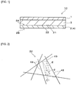
- FIG. 1 shows a cross-section of an absorbent article 10 of the embodiment.
- the absorbent article 10 includes a liquid permeable top layer 1 arranged on the skin-contacting surface side, a leak-proof layer 2 arranged on the non-skin-contacting surface side, and a liquid-holding absorbent layer 3 disposed between the top layer 1 and the leak-proof layer 2.
- the absorbent layer 3 is a layer of a hydrophilic material arranged on the non-skin-contacting surface side of the top layer 1, and may contain not only an aggregate (absorbent core) of liquid absorbers such as pulp and an absorbent polymer but also a covering sheet (also referred to as a core wrap sheet) that covers the aggregate of liquid absorbers.
- Specific examples of the covering sheet include a liquid-permeable fiber sheet such as a thin paper (tissue paper) and a nonwoven fabric.
- the leak-proof layer 2 is directly stacked on the absorbent layer 3. That is, the leak-proof layer 2 and the absorbent layer 3 are stacked without presence of other layers between both except for an agent (adhesive or the like) used for bonding.
- the leak-proof layer 2 forms a layer closest to the non-skin-contacting surface side of the absorbent article 10.
- the leak-proof layer need not necessarily be the layer closest to the non-skin-contacting surface side.
- the absorbent article according to the present invention is a sanitary napkin or the like
- an adhesive for fixing the article to clothing on the non-skin-contacting surface side of the leak-proof layer a release paper for covering the adhesive until the adhesive is used, or the like may be arranged.
- the absorbent article 10 of the embodiment preferably includes no film on the non-skin-contacting surface side of the absorbent layer 3.
- the leak-proof layer 2 preferably includes a surface 21 on an absorbent layer side 2A in contact with the absorbent layer 3 and a surface 22 on a non-absorbent layer side 2B.
- the surface 22 on the non-absorbent layer side 2B of the leak-proof layer 2 preferably constitutes an outer surface of the absorbent article 10.
- the leak-proof layer 2 includes a fiber layer 4 such as a nonwoven fabric or the like as a component. Specifically, as shown in FIG. 3 , the leak-proof layer 2 has a fiber layer 4 including a meltblown layer 41 and a protective layer 42 of the meltblown layer 41.
- the protective layer 42 is preferably arranged at least on the non-absorbent layer side of the meltblown layer 41.
- the protective layer 42 is a layer which reinforces strength or the like of the meltblown layer 41.
- the leak-proof layer 2 preferably includes an embossed part (not shown) in which the meltblown layer 41 and the protective layer 42 are bonded, and a non-embossed part (not shown) other than the embossed part.
- the embossed part herein means a region in which constituent fibers of the fiber layer 4 are consolidated by heat embossing. In the embossed part formed in the fiber layer 4 by this consolidation, a thickness thereof is reduced, as compared with other sites of the fiber layer 4.
- the embossed part has a circular or rectangular shape, for example, and can be formed in a scatter form over a whole area of the fiber layer 4.
- a plurality of lines of linear or curved embossed parts can also be formed. The plurality of lines of the linear or curved embossed parts can also be formed so that the plurality of lines thereof may cross with each other.
- the leak-proof layer 2 includes synthetic fibers as constituent fibers, and preferably has water-repellency. Thereby the leak-proof layer 2 includes a function of preventing the excreted liquid which is permeated from the top layer 1 and absorbed in the absorbent layer 3 from leaking to an outside of the absorbent article 10. Therefore the leak-proof layer 2 including the fiber layer 4 as a component preferably includes the following fiber structure in a region in which the leak-proof layer 2 overlaps with the absorbent layer 3.
- the leak-proof layer 2 preferably includes, in a region in which the leak-proof layer 2 overlaps with the absorbent layer 3, a non-opening region in the non-embossed part.
- the non-opening region is a region which does not include the "through-hole in which, in a plane view, an interfiber space containing a region in which an area of a rectangle formed of 10 ⁇ m in a diagonal line length reaches 25 ⁇ m 2 or more passes therethrough in the thickness direction" (hereinafter, referred to as the through-hole).
- a size of the "region in which the area of the rectangle formed of 10 ⁇ m in the diagonal line length reaches 25 ⁇ m 2 or more" is a size at which water seepage from the leak-proof layer is concerned about in the following state: namely, in the state in which the excreted liquid in the absorbent article arrives at the leak-proof layer from a top layer, and a seating pressure is applied to water (liquid such as the excreted liquid which is absorbed by the absorbent article).
- the through-hole is a hole which passes therethrough in the thickness direction at a predetermined size according to the definition described above, and the "non-opening region" which does not include the through-hole may be confirmed from either the surface 21 on the absorbent layer side 2A of the leak-proof layer 2, or the surface 22 on the non-absorbent layer side 2B thereof.
- the "plane view” herein means to observe a sheet surface (the surface 21 on the absorbent layer side 2A, or the surface 22 on the non-absorbent layer side 2B) of the leak-proof layer 2 from above.
- the "hole which passes therethrough in the thickness direction” herein means a hole in which, “in the plane view, the interfiber space in which the area of the rectangle formed of 10 ⁇ m in the diagonal line length reaches 25 ⁇ m 2 or more" passes therethrough in the thickness direction of the leak-proof layer 2 while including the area.
- requirements for the diagonal line length and the area described above to be specified on the "through-hole" herein mean a seepage size upon application of the seating pressure to water in a relation with the excreted liquid to be absorbed in the absorbent article.
- Presence or absence of the through-hole can be measured by the method as follows.
- the sheet surface (the surface 21 on the absorbent layer side 2A or the surface 22 on the non-absorbent layer side 2B) of the leak-proof layer 2 is observed at an observation magnification of 3,000 times by using a scanning electron microscope (SEM) (manufactured by JEOL Co., Ltd., JCM-6000PLUS (trade name), for example, which is the same also in other places of this specification) to identify the interfiber space which passes therethrough without being blocked by the fibers when viewed from front to depth (the thickness direction of the leak-proof layer 2) of an observation screen (or image pick-up screen).
- SEM scanning electron microscope
- the area of the rectangle is calculated based on the following Formula [1]. A smaller one of angles at the midpoint at which the straight lines cross in the rectangle mentioned above is taken as a crossing angle ⁇ (0° ⁇ ⁇ ⁇ 90°) to measure the crossing angle ⁇ .
- Area of rectangle 1 / 2 ⁇ Diagonal line length : 10 ⁇ m 2 ⁇ sin ⁇
- a case where the leak-proof layer 2 does not include the through-hole defined above includes the aspect as described below, for example. That is, even if the interfiber space which satisfies the requirements for the diagonal line and the area described above is present on a front surface upon the plane view, when the fibers which block this interfiber space are present in depth thereof and the "hole" does not pass therethrough in the thickness direction with keeping the size described above, the leak-proof layer 2 does not include the through-hole described above. Also when a hole as small as the rectangle having the diagonal line of 10 ⁇ m in length cannot be drawn is present in the interfiber space which is visible on a front side upon observing the through-hole in the plane view, the leak-proof layer 2 does not include the through-hole described above, either.
- the leak-proof layer 2 does not include the through-hole described above, either.
- a method to enable the leak-proof layer 2 to have the non-opening region without the through-hole defined above include various methods, such as a method for increasing the number of fibers by increasing a basis weight.
- the leak-proof layer 2 preferably includes a structure shown below.
- the leak-proof layer 2 in a laminated structure of the meltblown layer 41 and the protective layer 42 mentioned above, preferably includes a raised region 6 in which the number of fibers of the meltblown layer 41 for the fibers which penetrate into the protective layer 42 is 2.5 fibers/mm or more in the region which overlaps with the absorbent layer 3 (see a partially enlarged drawing in a circle shown by a symbol P in FIG. 3 ).
- the "raised region 6" herein means a fiber structure inside the leak-proof layer 2, as described above. That is, inside the leak-proof layer 2, a part including a structure in which part of fibers (one end part of the fiber, for example) is protruded from a fiber aggregate 41B constituting the meltblown layer 41, and the protruded fibers (raised fibers) 41A penetrate into space between fibers 42A of the protective layer 42 is referred to as the "raised region 6".
- the protective layer 42 into which the fibers of the meltblown layer 41 penetrate is preferably arranged on the non-absorbent layer side 2B of the meltblown layer 41.
- the laminated structure of the leak-proof layer 2 is not limited to an embodiment of a two-layer structure as shown in FIG. 3 , and insofar as the laminated structure includes the protective layer 42 at least on the non-absorbent layer side 2B, the laminated structure may include a structure haing three or more layers.
- the laminated structure may also be a structure having another protective layer 43 on the absorbent layer side 2A in addition to the protective layer 42 on non-absorbent layer side 2B of the meltblown layer 41.
- the meltblown layer 41 may be formed into two or more layers, or each of the protective layers 42 and 43 may be formed into two or more layers.
- the leak-proof layer 2 preferably has the "raised region 6 in which the number of fibers of the meltblown layer 41 for the fibers which penetrate into the protective layer 42 is 2.5 fibers/mm or more" described above with as few laminations as possible (see a partially enlarged drawing in a circle shown by a symbol P in FIGs. 3 and 4 ).
- the raised region 6 mentioned above is present inside the leak-proof layer 2, thereby part of fibers of the meltblown layer 41 stands, and is arranged so that the fibers may bury the interfiber space of the leak-proof layer 2, even without excessively increasing the fiber amount of the leak-proof layer 2.
- the through-hole in the thickness direction is filled, and the leak-proof layer 2 has high liquid leakage prevention without adversely affecting softness.
- adjustment of the number of fibers which penetrate thereinto in the raised region 6 of the leak-proof layer 2 to be 2.5 fibers/mm or more means the number of fibers which fill the through-hole mentioned above.
- the number of fibers which penetrate from the meltblown layer 41 into the protective layer 42 in the raised region 6 is preferably 5 fibers/mm or more, and more preferably 10 fibers/mm or more. From a viewpoint of air permeability, the number of fibers which penetrate described above is preferably 100 fibers/mm or less, more preferably 50 fibers/mm or less, and further preferably 40 fibers/mm or less.
- the number of fibers which penetrate from the meltblown layer 41 into the protective layer 42 in the raised region 6 is preferably 2.5 fibers/mm or more and 100 fibers/mm or less, more preferably 5 fibers/mm or more and 50 fibers/mm or less, and further preferably 10 fibers/mm or more and 40 fibers/mm or less.
- the number of fibers of the meltblown layer 41 which penetrate into the protective layer 42 can be measured by a method described below.
- the leak-proof layer 2 in the region which overlaps with the absorbent layer is taken out according to the method shown in (Method for measuring through-hole) mentioned above.
- the taken out leak-proof layer 2 is cut in the thickness direction to obtain a cross section.
- the leak-proof layer 2 is placed on an observation stage so that the cross section may face up to observe a cut surface at an observation magnification of 100 times by using the SEM.
- a length (length in a plane direction in a leak-proof layer cross section) of a visual field the visual field in one place when the leak-proof layer is observed by the SEM is adjusted to 1 mm to measure the numbers in ten places.
- the number of raised fibers 41A which penetrate from the meltblown layer 41 into the protective layer 42 on the non-absorbent layer side 2B is counted on each place.
- a total of the numbers counted in the ten places described above is taken as a numerator to calculate the number based on the following Formula [2].
- Number of fibers of meltblown layer for fibers which penetrate into protective layer 42 number of fibers of meltblown layer 41 for fibers which penetrate into protective layer 42 in observation visual field fibers / L length of interface of protective layer 42 and meltblown layer 41 in observation visual field 10 mm
- the cut surface in the thickness direction to be observed include a SEM image as shown in FIG. 5 .
- a three-layer structure of the protective layer (spunbond layer) 43 on the absorbent layer side 2A, the meltblown layer 41, and the protective layer (spunbond layer) 42 on the non-absorbent layer side 2B is formed.
- the raised fibers 41A protruded from the fiber aggregate 41B constituting the meltblown layer 41 penetrate into space between the fibers 42A of the protective layer 42 on the non-absorbent layer side 2B.
- the fibers of the meltblown layer 41 for the fibers which penetrate into the protective layer 42 are preferably formed as shown in a SEM image shown in FIG. 6 , for example, when observed from the surface 22 on the non-absorbent layer side 2B. That is, as shown in a box region of a long dashed short dashed line in the SEM image of FIG. 6 , the raised fibers 41A of the meltblown layer 41 are preferably formed into a state in which the raised fibers 41A are entangled with the fibers 42A of the protective layer 42, while the raised fibers 41A penetrate into space between the fibers 42A of the protective layer 42. Thereby penetration of the raised fibers 41A of the meltblown layer 41 into the protective layer 42 is further stably held.
- the protective layers 42 and 43 are arranged on both surfaces of the meltblown layer 41.
- the raised region 6 is preferably arranged on the non-absorbent layer side 2B. This is because, from a viewpoint of liquid leakage prevention, a state of the raised fibers is held. More specifically, this is because a fiber structure of the raised region 6 is protected from a pressure of the liquid which migrates from the absorbent layer 3 to prevent the through-hole from being generated when in use of the absorbent article.
- the raised region 6 may be arranged on both the non-absorbent layer side 2B and the absorbent layer side 2A.
- the raised region 6 is preferably arranged on a region as a whole in which the leak-proof layer 2 overlaps with the absorbent layer 3.
- the raised region 6 is more preferably arranged from a region which overlaps with the absorbent layer 3 to a plane region which does not overlap with the absorbent layer 3 beyond this region.
- the fibers of the meltblown layer 41 preferably are not exposed on the top surface (top surface of the surface 22) on the non-absorbent layer side 2B.
- a thickness of the protective layer 42 on the non-absorbent layer side 2B of the meltblown layer 41 can be adjusted to a predetermined level, or the fibers can also be immobilized by using a hot-melt adhesive or the like, for example.
- the fibers of the meltblown layer 41 are not exposed on the top surface (top surface of the surface 22) on the non-absorbent layer side 2B, and thereby the raised fibers of the meltblown layer 41 are protected, the fiber structure of the raised region 6 is held, and the liquid becomes difficult to seep out from the leak-proof layer 2.
- Presence or absence of the exposure described above can be confirmed by observing a top surface of an observation object at an observation magnification of 100 times by using the SEM.
- the fibers of the meltblown layer 41 are reflected on a topmost surface of the observation screen, the fibers of the meltblown layer are judged to be exposed on the top surface. If not, for example, when only the fibers of the protective layer are reflected on the topmost surface of the observation screen, the fibers are judged not to be exposed thereon.
- the "meltblown layer” herein means a fiber layer (layer of a nonwoven fabric of a type directly joined with spinning) formed by spinning a heated and melted thermoplastic resin, and allowing the resulting fibers to accumulate on a conveyor, thereby being processed into the nonwoven fabric according to a so-called meltblown method.
- meltblown method the melted resin output from nozzles of a spinneret is blown off by a jet flow of high-temperature gas to form ultra-micronized floc fibers in a tearing off manner. Therefore, the obtained meltblown layer is a layer of the nonwoven fabric formed of ultrafine fibers having a fiber diameter of 10 ⁇ m or less. Constituent fibers are formed of filament fibers having a fiber length of 30 ⁇ m or more. Interfiber distance is also small. Such the meltblown layer 41 is superior in feelings and barrier properties. On the other hand, reinforcement by the protective layer 42 is required on strength or wear resistance.
- an average fiber diameter (R1) of fibers of the meltblown layer 41 is preferably 2.5 ⁇ m or less, more preferably 1.5 ⁇ m or less, and further preferably 1 ⁇ m or less.
- the average fiber diameter (R1) is practically 0.1 ⁇ m or more.
- the average fiber diameter (R1) of fibers of the meltblown layer 41 is preferably 0.1 ⁇ m or more and 2.5 ⁇ m or less, more preferably 0.1 ⁇ m or more and 1.5 ⁇ m or less, and further preferably 0.1 ⁇ m or more and 1 ⁇ m or less.
- the average fiber diameter (R1) of fibers of the meltblown layer 41 is suppressed within the range described above, and thereby the interfiber space can be further narrowed to more definitely prevent the leak-proof layer 2 from including the through-hole mentioned above.
- the protective layer 42 is a fiber layer which reinforces the strength or the like of the meltblown layer 41, and is preferably formed by using fibers having a larger fiber diameter than a fiber diameter of the meltblown layer 41.
- the protective layer 42 insofar as the layer may reinforce the strength or the like of the meltblown layer 41, various fiber layers can be used. Among these, from a viewpoint of cost, the protective layer 42 is preferably formed of a spunbond layer.
- the "spunbond layer” herein means a layer of a nonwoven fabric which is produced by a so-called spunbond method.
- the spunbond layer is a fiber layer formed by spinning the heated and melted thermoplastic resin and allowing the resulting fibers to accumulate on a conveyor.
- the fibers are formed while cooling and drawing a melted resin output from nozzles from a spinneret.
- the obtained spunbond layer has larger fiber diameter than a fiber diameter of the meltblown layer, and is a fiber layer formed of fibers having long fiber length (filament). It is preferable that the spunbond layer is laminated on the meltblown layer, and then heat embossing is applied thereto, and the resulting product is processed into the nonwoven fabric in which both are integrated.
- the average fiber diameter (R1) of fibers of the meltblown layer 41 is preferably smaller than an average fiber diameter (R2) of fibers of the protective layer 42.
- a ratio (R1/R2) of the average fiber diameter (R1) of fibers of the meltblown layer 41 to the average fiber diameter (R2) of fibers of the protective layer 42 is preferably 1/8 or less, more preferably 1/20 or less, and further preferably 1/25 or less.
- the ratio (R1/R2) is preferably 1/100 or more, more preferably 1/50 or more, and further preferably 1/40 or more.
- the ratio (R1/R2) is preferably 1/100 or more and 1/8 or less, more preferably 1/50 or more and 1/20 or less, and further preferably 1/40 or more and 1/25 or less.
- An art is referred to, in which five small-piece samples are collected from a meltblown layer of a leak-proof layer in a random manner, a photograph in which an observation magnification is increased, for example, to 1,000 to 10,000 times is taken so that 20 to 60 fibers may be taken in a visual field by using the SEM, a fiber diameter is measured on all the fibers within the visual field so that the fiber may be counted once for each, and the measured average value is rounded off to a first decimal place to calculate and determine an average fiber diameter.
- a filling rate is adjusted to preferably 25% or less, more preferably 20% or less, further preferably 10% or less, and particularly preferably 5% or less.
- the "filling rate” herein means a proportion of fibers per space. The filling rate of the meltblown layer 41 is suppressed within the range described above.
- the layer can include flexibility which may produce a gentle curved surface or pleat as in cloth (high drape property) to suppress hardness as in paper or a film (crisply feeling: hardness which needs a certain degree of force upon folding or the like, and is easily bent, and not curved upon twisting, for example: dry chafing sound which is generated when touched, or when twisted or the like).
- the filling rate of the meltblown layer 41 is preferably 2% or more, more preferably 2.5% or more, and further preferably 3% or more. Specifically, the filling rate of the meltblown layer 41 is preferably 2% or more and 25% or less, more preferably 2% or more and 20% or less, further preferably 2.5% or more and 10% or less, and particularly preferably 3% or more and 5% or less.
- the filling rate of the meltblown layer can be measured by the method described below.
- Mass of a measurement object leak-proof layer is measured.
- a cross section in a thickness direction of the leak-proof layer is observed by using the SEM described above, and the thickness of the meltblown layer is measured.
- the meltblown layer is taken out based on (Method for measuring basis weight of meltblown layer) described later.
- the basis weight is calculated, and the filling rate is calculated by the expression: ⁇ basis weight of meltblown layer / (thickness of meltblown layer ⁇ density of resin) ⁇ ⁇ 100.
- the meltblown layer taken out therefrom is pressed at 180°C by LABO PRESS (manufactured by Toyo Seiki Seisaku-Sho, Ltd., model P2-30), and for 1 minute by a two-step press (low pressure: 5 kg/cm 3 , high pressure: 150 kg/cm 3 ), and then for 1 minute by a cooling press to prepare a film. Then, the film is cut into 10 ⁇ 10 cm from a place in which air is not entrained, mass is measured, and then the resulting value is divided by a volume to calculate the resin density.
- LABO PRESS manufactured by Toyo Seiki Seisaku-Sho, Ltd., model P2-30
- the basis weight of the meltblown layer 41 is preferably 20 g/m 2 or less, more preferably 15 g/m 2 or less, and further preferably 10 g/m 2 or less.
- the basis weight of the meltblown layer 41 is preferably 3 g/m 2 or more, more preferably 4 g/m 2 or more, and further preferably 5 g/m 2 or more.
- the basis weight of the meltblown layer 41 is preferably 3 g/m 2 or more and 20 g/m 2 or less, more preferably 4 g/m 2 or more and 15 g/m 2 or less, and further preferably 5 g/m 2 or more and 10 g/m 2 or less.
- the basis weight of the meltblown layer can be measured as described below.
- Mass of a measurement object leak-proof layer is measured in a dry state.
- a cross section in a thickness direction of the leak-proof layer is observed by using the SEM described above, and the thickness of each of the meltblown layer and the protective layer and a thickness ratio thereof are measured.
- the following means are used. When the meltblown layer and the protective layer are bonded with the hot-melt or the like, the meltblown layer is carefully peeled off using a cold spray. Mass of the meltblown layer is measured, and the resulting value is divided by a sheet area of the leak-proof layer to calculate the basis weight of the meltblown layer.
- meltblown layer and the protective layer are thermally bonded by embossing or the like, an embossed part is removed, and then the meltblown layer is carefully peeled off by hand, tweezers, or the like. Then, the mass of the meltblown layer is measured, and the resulting value is divided by a value obtained by subtracting an area of the embossed part from the sheet area of the leak-proof layer to calculate the basis weight of the meltblown layer.
- a preferable method for producing a nonwoven fabric serving as the leak-proof layer 2 of the embodiment will be described.
- a case where the protective layer 42 is applied as a spunbond layer will be described herein.
- the meltblown layer 41 ultrafine fibers are accumulated on a belt conveyor by a meltblown method to continuously convey a meltblown layer raw material in a machine direction.
- the fiber diameter, the filling rate, and the basis weight mentioned above can be satisfied by setting various conditions such as a diameter of the nozzle of the spinneret, an air speed and a temperature of the jet flow of high-temperature gas.
- the protective layer 42 a spunbond layer raw material is laminated on a surface of the meltblown layer raw material described above by the spunbond method.
- raising treatment is preferably applied to the surface of the meltblown layer raw material in an upstream of a front in which the spunbond layer raw material is laminated thereon. Thereby the spunbond layer raw material is laminated on a raising-treated surface of the meltblown layer raw material, and the raised region 6 mentioned above is formed.
- the raising treatment can be conducted by various methods ordinarily used for a method for producing a nonwoven fabric.
- the raising treatment is conducted by rotating a convex roll having a plurality of convex parts on a peripheral surface while the convex roll is brought into contact with the surface of the meltblown layer raw material. Thereby the raised fibers can be formed.
- the fibers that are output, cooled and drawn by the spunbond method and serving as the spunbond layer raw material are accumulated.
- the raised fibers of the meltblown layer raw material penetrate into space between the fibers of the spunbond layer raw material, and the raised region 6 in the leak-proof layer 2 of the embodiment is formed.
- the nonwoven fabric serving as the leak-proof layer 2 of the embodiment can be produced.
- a structure of the "number of fibers of the meltblown layer for the fibers which penetrate into the protective layer is 2.5 fibers/mm or more" in the raised region 6 can be formed by protrusion of part of fibers (one end part of the fiber, for example) from the fiber aggregate 41B constituting the meltblown layer 41 and penetration of the protruded fibers (raised fibers) 41A into space between the fibers 42A of the protective layer 42 on the non-absorbent layer side 2B.
- a desired average fiber diameter, filling rate, basis weight or the like can be obtained by appropriately setting various production conditions.
- a protective layer 43 formed of the spunbond layer can be further arranged on a surface serving as the absorbent layer side 2A of the meltblown layer raw material.
- a step for producing the spunbond layer raw material in the same manner described above may further be provided in an upstream of the step for producing the meltblown layer raw material.
- the meltblown layer raw material is formed on the spunbond layer raw material produced in an upstream.
- the nonwoven fabric obtained by the producing method described above is directly stacked on the absorbent layer as the leak-proof layer.
- the top layer is stacked on the absorbent layer with the leak-proof layer (nonwoven fabric) which are directly stacked on the skin-contacting surface side of the absorbent layer, and the resulting product is integrated to produce the absorbent article according to the present invention.
- the method may include a step of assembling other members, when necessary.
- Constituent fibers of the meltblown layer 41 of the leak-proof layer 2, and constituent fibers in the case where the protective layers 42 and 43 are formed of spunbond layers, are formed of a thermoplastic resin.
- the thermoplastic resins include one or more selected from a polyolefin-based resin, a polyester-based resin, a polyamide-based resin, an acrylonitrile-based resin, a vinyl-based resin and a vinylidene-based resin.
- Specific examples of the polyolefin-based resin include one or more selected from polyethylene, polypropylene and polybutene.
- Specific examples of the polyester-based resin include one or more selected from polyethylene terephthalate and polybutylene terephthalate.
- polyamide-based resin examples include one or more selected from nylon and the like.
- vinyl-based resin examples include polyvinyl chloride and the like.
- vinylidene-based resin examples include polyvinylidene chloride.
- a modified product or a mixture of various resins described above can also be used.
- a spunbond layer raw material is formed having an average fiber diameter of 20 ⁇ m and a basis weight of 9 g/m 2 , using a polyolefin resin by a spunbond method.
- a meltblown layer raw material is formed having a basis weight of 10 g/m 2 thereon, using a polyolefin resin by a meltblown method (spinning temperature: 270°C). Raising treatment was conducted onto a whole surface of the meltblown layer raw material. Specifically, the meltblown layer raw material was chafed once at 1.2 m/min in a machine direction of the meltblown layer raw material, while applying a pressure of 165 Pa thereto, by Sheet Paper, manufactured by TRUSCO NAKAYAMA CORPORATION, catalog number: GBS-600-5P.
- An average fiber diameter, a thickness, and a filling rate of the obtained meltblown layer were measured based on (Method for measuring average fiber diameter), (Method for measuring filling rate of meltblown layer), and (Method for measuring basis weight of meltblown layer) described above.
- the spunbond layer raw material having the average fiber diameter of 20 ⁇ m and the basis weight of 9 g/m 2 was formed, using the polyolefin resin by the spunbond method.
- SMS spunbond-meltblown-spunbond
- Example 1 Thereby a leak-proof layer sample in Example 1 was prepared, in which spunbond layers arranged on both surfaces of a meltblown layer 41 were applied as protective layers 42 and 43.
- the number of fibers of the meltblown layer 41 for the fibers which penetrated into the protective layer from a raising-treated surface of the meltblown layer 41 was measured based on (Method for measuring number of fibers which penetrate thereinto) mentioned above, and was shown as in Table 1 (hereinafter, the same in Examples 2 and 3).
- a leak-proof layer sample in Example 2 was prepared in the same manner as in Example 1 except that a meltblown layer 41 was applied as shown in Table 1.
- the fiber diameter described above was realized by changing a spinning temperature of the meltblown layer in Example 1 to a low temperature (255°C).
- a leak-proof layer sample in Example 3 was prepared in the same manner as in Example 1 except that a meltblown layer 41 was applied as shown in Table 1.
- the fiber diameter described above was realized by changing a spinning temperature of the meltblown layer in Example 1 to 265°C.
- a leak-proof layer sample in Comparative Example 1 was prepared in the same manner as in Example 1 except that a meltblown layer 41 was applied as described in Table 1 without conducting raising treatment thereto. Formation of fibers which slightly penetrated thereinto, irrespective of no raising treatment, was caused by a pressure applied thereto upon lamination.
- a leak-proof layer sample in Comparative Example 2 was prepared in the same manner as in Example 2 except that a meltblown layer 41 was applied as described in Table 1 without conducting raising treatment thereto.
- a leak-proof layer sample in Comparative Example 3 was prepared in the same manner as in Example 1 except that a meltblown layer 41 was applied as shown in Table 1.
- the fiber diameter was realized by changing a spinning temperature of the meltblown layer in Example 1 to a low temperature (250°C).
- a leak-proof layer sample in Comparative Example 4 was prepared in the same manner as in Example 3 except that a meltblown layer 41 was applied as described in Table 1 by enhancing a filling rate by calender treatment without conducting raising treatment thereto.
- a spunbond layer raw material and a meltblown layer raw material which were the same as in Example 2 were prepared one for each, and in a state in which both raw materials were overlapped, a water flow was jetted twice at water pressures different from each other from a meltblown layer raw material side.
- First jetting was performed at a low pressure (2.5 MPa) using a nozzle having a diameter of 0.12 mm to entangle constituent fibers of the spunbond layer raw material and the meltblown layer raw material, and simultaneously both layers were wetted with water and well fitted.
- Second jetting was performed at a high pressure (5 MPa) using a nozzle having a diameter of 0.1 mm to further entangle the constituent fibers of the spunbond layer raw material and the meltblown layer raw material to obtain an SM nonwoven fabric formed of two layers of a spunbond-meltblown (SM).
- SM spunbond-meltblown
- a leak-proof layer sample in Comparative Example 6 was prepared in the same manner as in Comparative Example 5 except that a pressure of a water flow to be jetted was adjusted to 1.75 MPa for first jetting, and to 3.5 MPa for second jetting.
- a leak-proof layer sample in Comparative Example 7 was prepared in the same manner as in Comparative Example 5 except that a pressure of a water flow to be jetted was adjusted to 1 MPa for first jetting, and to 2 MPa for second jetting.
- a specimen prepared by cutting the leak-proof layer sample into 8 cm ⁇ 8 cm was placed on a filter paper (manufactured by Advantech Toyo Co., Ltd., No. 2, diameter: 70 mm).
- the leak-proof layer sample was placed thereon with a surface on a non-absorbent layer side 2B (surface with a raised region) directed toward the filter paper.
- a specimen prepared by cutting a dry pulp sheet manufactured by Lion Corporation, Lead Healthy Cooking Paper Double (trade name), basis weight: 40 g/m 2 ) into 8 cm ⁇ 8 cm was placed.
- Presence or absence of seepage was confirmed by a method for visually confirming coloring to the filter paper.
- An amount of deionized water seeped out to the filter paper was confirmed by subtracting a weight before testing from a weight after testing as measured by an electronic balance.
- Sensory evaluation of softness was performed by asking five panels (persons engaged in research in an absorbent article field) to rub surfaces (both surfaces) of each nonwoven fabric sample by hand. After asking each panel to score the evaluation based on the evaluation criteria described below, an average value of evaluation scores of five persons was taken as a score of the sensory evaluation of softness of each sample.
- a hot-melt was dissolved by using an organic solvent (butyl acetate) for a disposable diaper (manufactured by Kao Corporation, Merries (registered trademark), Merries Pants, M size, 2017) to remove the most exterior (non-skin surface side) nonwoven fabric and a film being the leak-proof layer, and the resulting specimen was dried for one day in a draft, and then was used.
- the leak-proof layer samples in Examples 1 to 3 in which the number of fibers of the meltblown layer for the fibers which penetrated into the protective layer was 2.5 fibers/mm or more and the layers had no through-holes were superior in liquid leakage prevention to the leak-proof layer samples in Comparative Example 1, 2 and 4 in which the number of fibers of the meltblown layer for the fibers which penetrated into the protective layer was less than 2.5 fibers/mm and the layers had the through-holes.
- the leak-proof layer samples in Examples 1 to 3 had significantly higher liquid leakage prevention in contrast with the leak-proof layer samples in Comparative Examples 5 to 7.
- the raised region was formed by a hydroentangling method, thereby causing movement of fibers of the meltblown layer by a pressure of the water flow to develop the through-holes of 25 ⁇ m 2 or more in Comparative Examples 5 to 7, the raised region was formed by raising treatment, and further the movement of fibers of the meltblown layer was able to be suppressed by heat embossing in Examples 1 to 3.
- this is also because exposure of fibers of the meltblown layer to the top surface on the non-absorbent layer side of the leak-proof layer was able to be prevented in the leak-proof layer samples in Examples 1 to 3.
Landscapes
- Health & Medical Sciences (AREA)
- Engineering & Computer Science (AREA)
- Epidemiology (AREA)
- General Health & Medical Sciences (AREA)
- Veterinary Medicine (AREA)
- Vascular Medicine (AREA)
- Life Sciences & Earth Sciences (AREA)
- Animal Behavior & Ethology (AREA)
- Biomedical Technology (AREA)
- Public Health (AREA)
- Heart & Thoracic Surgery (AREA)
- Dermatology (AREA)
- Manufacturing & Machinery (AREA)
- Textile Engineering (AREA)
- Physics & Mathematics (AREA)
- Fluid Mechanics (AREA)
- Absorbent Articles And Supports Therefor (AREA)
- Nonwoven Fabrics (AREA)
Abstract
Description
- The present invention relates to an absorbent article, such as a sanitary napkin or a diaper.
- Nonwoven fabric is often used in an absorbent article such as a sanitary napkin from a viewpoint of texture or the like. Various proposals have been offered regarding such nonwoven fabrics.
- For example,
Patent Literature 1 describes a nonwoven fabric including raised fibers incorporated with free fibers intersecting the raised fibers from a viewpoint of improving texture of the nonwoven fabric. -
Patent Literature 2 describes an absorbent article having a barrier layer containing a spunbond nonwoven fabric web and a meltblown nonwoven fabric web. From a viewpoint of providing the barrier layer with not only barrier properties but also high flexibility and softness for the sensitive skin, number average fiber diameter of each nonwoven fabric web and total weight percentage of the meltblown nonwoven fabric web are held within specific ranges. -
- Patent Literature 1:
JP-A-2016-65335 - Patent Literature 2:
JP-T-2011-529749 - The present invention provides an absorbent article including a top layer, a leak-proof layer, and an absorbent layer disposed between the top layer and the leak-proof layer, in which the leak-proof layer is directly stacked on the absorbent layer, and the leak-proof layer includes a meltblown layer and a protective layer of the meltblown layer.
- In an embodiment, the leak-proof layer includes an embossed part in which the meltblown layer and the protective layer are bonded, and a non-embossed part other than the embossed part.
- In an embodiment, the leak-proof layer includes a non-opening region in the non-embossed part.
- In an embodiment, the non-opening region is a region which does not include a through-hole in which, in a plane view of the leak-proof layer, an interfiber space containing a region in which an area of a rectangle formed of 10 µm in a diagonal line length reaches 25 µm2 or more passes therethrough in a thickness direction.
- In an embodiment, the non-opening region is arranged on a region in which the leak-proof layer overlaps with the absorbent layer.
- In an embodiment, the protective layer is arranged on a non-absorbent layer side of the meltblown layer.
- In an embodiment, the leak-proof layer includes a raised region in which the number of fibers of the meltblown layer for the fibers which penetrate into the protective layer is 2.5 fibers/mm or more.
- In an embodiment, an average fiber diameter of fibers of the meltblown layer is 2.5 µm or less.
- In an embodiment, the raised region is arranged on a region in which the leak-proof layer overlaps with the absorbent layer.
- Other and further objects, features and advantages of the invention will appear more fully from the following description, appropriately referring to the accompanying drawings.
-
- {
FIG. 1 }
FIG. 1 is a cross-sectional drawing showing one embodiment of an absorbent article according to the present invention. - {
FIG. 2 }
FIG. 2 is an explanatory drawing schematically showing a method for confirming a "region in which an area of a rectangle formed of 10 µm in a diagonal line length reaches 25 µm2 or more" for a nonwoven fabric constituting a leak-proof layer of an absorbent article according to the present invention. - {
FIG. 3 }
FIG. 3 is a partially enlarged cross-sectional drawing schematically showing a preferable embodiment of a nonwoven fabric constituting a leak-proof layer of an absorbent article according to the present invention. - {
FIG. 4 }
FIG. 4 is a partially enlarged cross-sectional drawing schematically showing another preferable embodiment of a nonwoven fabric constituting a leak-proof layer of an absorbent article according to the present invention. - {
FIG. 5 }
FIG. 5 is a drawing substitute photograph taking a cross section of the nonwoven fabric corresponding toFIG. 4 . - {
FIG. 6 }
FIG. 6 is a drawing substitute photograph taken from a surface of a non-absorbent layer side of the nonwoven fabric shown inFIG. 5 . - The present invention relates to an absorbent article including the leak-proof layer formed of a nonwoven fabric in which liquid leakage prevention is enhanced without adversely affecting softness.
- Even in conventional nonwoven fabrics as described in
Patent Literatures - A conceivable countermeasure is to close the through-holes to some extent by decreasing fiber diameter or increasing basis weight of the nonwoven fabric to thereby fill interfiber joints. However, since this method increases fiber amount, it may harden and adversely affect feel of the nonwoven fabric and therefore does not offer a viable solution to achieving a leak-proof layer in an absorbent article in contact with the skin.
- In calender treatment used in a conventional method for producing nonwoven fabric, interfiber openings can be filled to some extent upon compressing the fibers. However, in fiber-free regions, it is difficult to completely fill the through-holes that become the cause of liquid leakage. If increase of thermocompression bonding by calender treatment is resorted to (compression bonding force is strengthened or compression bonding area is increased), hardening of the nonwoven fabric by flattening of fibers progresses and softness is lost accordingly.
- On the other hand, the absorbent article according to the present invention includes a leak-proof layer formed of a nonwoven fabric in which liquid leakage prevention is enhanced without adversely affecting softness.
- An absorbent article according to the present invention will be explained below based on a preferred embodiment thereof, referring to the drawings. The nonwoven fabric according to the present invention can be applied to various materials which absorbs and retains excreted liquid. For example, the nonwoven fabric can be used in a diaper, a sanitary napkin, a panty liner, an incontinence pad and a urine pad.
- In the present invention, unless particularly stated otherwise, a side that is brought into contact with the human body is referred to as skin-facing surface side, skin-contacting surface side, or top surface side, and a side that is opposite to the above-mentioned side is referred to as non-skin-facing surface side, non-skin-contacting surface side, or back surface side. Especially, the skin-contacting surface side and the non-skin-contacting surface side of a leak-proof layer are referred to as an absorbent layer side and a non-absorbent layer side in several cases. The direction normal to the top surface or the back surface of the absorbent article is referred to as a thickness direction, and an amount thereof is referred to as thickness.
-
FIG. 1 shows a cross-section of anabsorbent article 10 of the embodiment. Theabsorbent article 10 includes a liquid permeabletop layer 1 arranged on the skin-contacting surface side, a leak-proof layer 2 arranged on the non-skin-contacting surface side, and a liquid-holdingabsorbent layer 3 disposed between thetop layer 1 and the leak-proof layer 2. Theabsorbent layer 3 is a layer of a hydrophilic material arranged on the non-skin-contacting surface side of thetop layer 1, and may contain not only an aggregate (absorbent core) of liquid absorbers such as pulp and an absorbent polymer but also a covering sheet (also referred to as a core wrap sheet) that covers the aggregate of liquid absorbers. Specific examples of the covering sheet include a liquid-permeable fiber sheet such as a thin paper (tissue paper) and a nonwoven fabric. - The leak-
proof layer 2 is directly stacked on theabsorbent layer 3. That is, the leak-proof layer 2 and theabsorbent layer 3 are stacked without presence of other layers between both except for an agent (adhesive or the like) used for bonding. In theabsorbent article 10 of the embodiment, the leak-proof layer 2 forms a layer closest to the non-skin-contacting surface side of theabsorbent article 10. However, in the absorbent article according to the present invention, the leak-proof layer need not necessarily be the layer closest to the non-skin-contacting surface side. For example, when the absorbent article according to the present invention is a sanitary napkin or the like, an adhesive for fixing the article to clothing on the non-skin-contacting surface side of the leak-proof layer, a release paper for covering the adhesive until the adhesive is used, or the like may be arranged. Theabsorbent article 10 of the embodiment preferably includes no film on the non-skin-contacting surface side of theabsorbent layer 3. The leak-proof layer 2 preferably includes asurface 21 on anabsorbent layer side 2A in contact with theabsorbent layer 3 and asurface 22 on anon-absorbent layer side 2B. Thesurface 22 on thenon-absorbent layer side 2B of the leak-proof layer 2 preferably constitutes an outer surface of theabsorbent article 10. - The leak-
proof layer 2 includes afiber layer 4 such as a nonwoven fabric or the like as a component. Specifically, as shown inFIG. 3 , the leak-proof layer 2 has afiber layer 4 including ameltblown layer 41 and aprotective layer 42 of themeltblown layer 41. Theprotective layer 42 is preferably arranged at least on the non-absorbent layer side of themeltblown layer 41. Theprotective layer 42 is a layer which reinforces strength or the like of themeltblown layer 41. The leak-proof layer 2 preferably includes an embossed part (not shown) in which themeltblown layer 41 and theprotective layer 42 are bonded, and a non-embossed part (not shown) other than the embossed part. The embossed part herein means a region in which constituent fibers of thefiber layer 4 are consolidated by heat embossing. In the embossed part formed in thefiber layer 4 by this consolidation, a thickness thereof is reduced, as compared with other sites of thefiber layer 4. The embossed part has a circular or rectangular shape, for example, and can be formed in a scatter form over a whole area of thefiber layer 4. Alternatively, a plurality of lines of linear or curved embossed parts can also be formed. The plurality of lines of the linear or curved embossed parts can also be formed so that the plurality of lines thereof may cross with each other. - The leak-
proof layer 2 includes synthetic fibers as constituent fibers, and preferably has water-repellency. Thereby the leak-proof layer 2 includes a function of preventing the excreted liquid which is permeated from thetop layer 1 and absorbed in theabsorbent layer 3 from leaking to an outside of theabsorbent article 10. Therefore the leak-proof layer 2 including thefiber layer 4 as a component preferably includes the following fiber structure in a region in which the leak-proof layer 2 overlaps with theabsorbent layer 3. - Namely, the leak-
proof layer 2 preferably includes, in a region in which the leak-proof layer 2 overlaps with theabsorbent layer 3, a non-opening region in the non-embossed part. The non-opening region is a region which does not include the "through-hole in which, in a plane view, an interfiber space containing a region in which an area of a rectangle formed of 10 µm in a diagonal line length reaches 25 µm2 or more passes therethrough in the thickness direction" (hereinafter, referred to as the through-hole). A size of the "region in which the area of the rectangle formed of 10 µm in the diagonal line length reaches 25 µm2 or more" is a size at which water seepage from the leak-proof layer is worried about in the following state: namely, in the state in which the excreted liquid in the absorbent article arrives at the leak-proof layer from a top layer, and a seating pressure is applied to water (liquid such as the excreted liquid which is absorbed by the absorbent article). The through-hole is a hole which passes therethrough in the thickness direction at a predetermined size according to the definition described above, and the "non-opening region" which does not include the through-hole may be confirmed from either thesurface 21 on theabsorbent layer side 2A of the leak-proof layer 2, or thesurface 22 on thenon-absorbent layer side 2B thereof. - The "plane view" herein means to observe a sheet surface (the
surface 21 on theabsorbent layer side 2A, or thesurface 22 on thenon-absorbent layer side 2B) of the leak-proof layer 2 from above. The "hole which passes therethrough in the thickness direction" herein means a hole in which, "in the plane view, the interfiber space in which the area of the rectangle formed of 10 µm in the diagonal line length reaches 25 µm2 or more" passes therethrough in the thickness direction of the leak-proof layer 2 while including the area. - Further, requirements for the diagonal line length and the area described above to be specified on the "through-hole" herein mean a seepage size upon application of the seating pressure to water in a relation with the excreted liquid to be absorbed in the absorbent article.
- Presence or absence of the through-hole can be measured by the method as follows.
- That is, the sheet surface (the
surface 21 on theabsorbent layer side 2A or thesurface 22 on thenon-absorbent layer side 2B) of the leak-proof layer 2 is observed at an observation magnification of 3,000 times by using a scanning electron microscope (SEM) (manufactured by JEOL Co., Ltd., JCM-6000PLUS (trade name), for example, which is the same also in other places of this specification) to identify the interfiber space which passes therethrough without being blocked by the fibers when viewed from front to depth (the thickness direction of the leak-proof layer 2) of an observation screen (or image pick-up screen). Whether or not the rectangle (including a square) in which two straight lines in a 10 µm scale cross at a midpoint can be drawn relative to this interfiber space is examined. Then, when the area of the rectangle is 25 µm2 or more, the through-hole is judged to be present. - The area of the rectangle is calculated based on the following Formula [1]. A smaller one of angles at the midpoint at which the straight lines cross in the rectangle mentioned above is taken as a crossing angle θ (0° ≤ θ ≤ 90°) to measure the crossing angle θ. The area of the rectangle in which the crossing angle θ is formed to be 30° or more with the diagonal line of 10 µm reaches 25 µm2 or more.

- When a leak-proof layer is taken out from a commercially available absorbent article for the measurement described above, a hotmelt adhering each inter-material is solidified by spraying a
cold spray 10 cm away from the most exterior side for about 5 seconds, and then the leak-proof layer is carefully peeled off. The means of taking out the leak-proof layer is applied to other measuring methods in this specification. - The method for measuring a through-hole described above can be performed as shown in
FIG. 2 , for example. That is, when the leak-proof layer 2 is observed from thesurface 21 on theabsorbent layer side 2A, or thesurface 22 on thenon-absorbent layer side 2B, aspace 49 which is surrounded byfibers 48, and is not blocked by other fibers in the thickness direction is identified. Subsequently, depending on whether or not a rectangle E in which two straight lines (drawn in the 10 µm scale and crossed at the midpoint, and the crossing angle is adjusted to be: θ = 30° or more and 90°or less) E1 and E1 are applied as the diagonal lines can be drawn, it is judged whether or not the through-hole defined above is present. When the rectangle E can be drawn, it is judged that an observation object leak-proof layer includes the through-hole. When the rectangle E cannot be drawn, it is judged that the observation object leak-proof layer does not include the through-hole. - A case where the leak-
proof layer 2 does not include the through-hole defined above includes the aspect as described below, for example. That is, even if the interfiber space which satisfies the requirements for the diagonal line and the area described above is present on a front surface upon the plane view, when the fibers which block this interfiber space are present in depth thereof and the "hole" does not pass therethrough in the thickness direction with keeping the size described above, the leak-proof layer 2 does not include the through-hole described above. Also when a hole as small as the rectangle having the diagonal line of 10 µm in length cannot be drawn is present in the interfiber space which is visible on a front side upon observing the through-hole in the plane view, the leak-proof layer 2 does not include the through-hole described above, either. In the same manner, also when a small hole in which the area of the rectangle drawn so that two straight lines in the 10 µm scale may cross at the midpoint does not reach 25 µm2 or more (namely, less than 25 µm2) is present, the leak-proof layer 2 does not include the through-hole described above, either. - Specific examples of a method to enable the leak-
proof layer 2 to have the non-opening region without the through-hole defined above include various methods, such as a method for increasing the number of fibers by increasing a basis weight. - Above all, from a viewpoint of keeping softness without excessively increasing a fiber amount to enhance liquid leakage prevention, the leak-
proof layer 2 preferably includes a structure shown below. - That is, with regard to the leak-
proof layer 2, in a laminated structure of themeltblown layer 41 and theprotective layer 42 mentioned above, the leak-proof layer 2 preferably includes a raisedregion 6 in which the number of fibers of themeltblown layer 41 for the fibers which penetrate into theprotective layer 42 is 2.5 fibers/mm or more in the region which overlaps with the absorbent layer 3 (see a partially enlarged drawing in a circle shown by a symbol P inFIG. 3 ). - The "raised
region 6" herein means a fiber structure inside the leak-proof layer 2, as described above. That is, inside the leak-proof layer 2, a part including a structure in which part of fibers (one end part of the fiber, for example) is protruded from afiber aggregate 41B constituting themeltblown layer 41, and the protruded fibers (raised fibers) 41A penetrate into space betweenfibers 42A of theprotective layer 42 is referred to as the "raisedregion 6". Theprotective layer 42 into which the fibers of themeltblown layer 41 penetrate is preferably arranged on thenon-absorbent layer side 2B of themeltblown layer 41. - The laminated structure of the leak-
proof layer 2 is not limited to an embodiment of a two-layer structure as shown inFIG. 3 , and insofar as the laminated structure includes theprotective layer 42 at least on thenon-absorbent layer side 2B, the laminated structure may include a structure haing three or more layers. For example, as shown inFIG. 4 , the laminated structure may also be a structure having anotherprotective layer 43 on theabsorbent layer side 2A in addition to theprotective layer 42 onnon-absorbent layer side 2B of themeltblown layer 41. Alternatively, although not shown, themeltblown layer 41 may be formed into two or more layers, or each of theprotective layers proof layer 2, the leak-proof layer 2 preferably has the "raisedregion 6 in which the number of fibers of themeltblown layer 41 for the fibers which penetrate into theprotective layer 42 is 2.5 fibers/mm or more" described above with as few laminations as possible (see a partially enlarged drawing in a circle shown by a symbol P inFIGs. 3 and 4 ). - The raised
region 6 mentioned above is present inside the leak-proof layer 2, thereby part of fibers of themeltblown layer 41 stands, and is arranged so that the fibers may bury the interfiber space of the leak-proof layer 2, even without excessively increasing the fiber amount of the leak-proof layer 2. As a result, the through-hole in the thickness direction is filled, and the leak-proof layer 2 has high liquid leakage prevention without adversely affecting softness. - From a viewpoint of liquid leakage prevention, adjustment of the number of fibers which penetrate thereinto in the raised
region 6 of the leak-proof layer 2 to be 2.5 fibers/mm or more means the number of fibers which fill the through-hole mentioned above. - From a viewpoint of liquid leakage prevention, the number of fibers which penetrate from the
meltblown layer 41 into theprotective layer 42 in the raisedregion 6 is preferably 5 fibers/mm or more, and more preferably 10 fibers/mm or more. From a viewpoint of air permeability, the number of fibers which penetrate described above is preferably 100 fibers/mm or less, more preferably 50 fibers/mm or less, and further preferably 40 fibers/mm or less. Specifically, the number of fibers which penetrate from themeltblown layer 41 into theprotective layer 42 in the raisedregion 6 is preferably 2.5 fibers/mm or more and 100 fibers/mm or less, more preferably 5 fibers/mm or more and 50 fibers/mm or less, and further preferably 10 fibers/mm or more and 40 fibers/mm or less. - The number of fibers of the
meltblown layer 41 which penetrate into theprotective layer 42 can be measured by a method described below. - When a leak-proof layer is taken out from a commercially available absorbent article, the leak-
proof layer 2 in the region which overlaps with the absorbent layer is taken out according to the method shown in (Method for measuring through-hole) mentioned above. The taken out leak-proof layer 2 is cut in the thickness direction to obtain a cross section. The leak-proof layer 2 is placed on an observation stage so that the cross section may face up to observe a cut surface at an observation magnification of 100 times by using the SEM. - With regard to a length (length in a plane direction in a leak-proof layer cross section) of a visual field, the visual field in one place when the leak-proof layer is observed by the SEM is adjusted to 1 mm to measure the numbers in ten places. The number of raised
fibers 41A which penetrate from themeltblown layer 41 into theprotective layer 42 on thenon-absorbent layer side 2B is counted on each place. A total of the numbers counted in the ten places described above is taken as a numerator to calculate the number based on the following Formula [2].
- Specific examples of the cut surface in the thickness direction to be observed include a SEM image as shown in
FIG. 5 . In the cross section of the leak-proof layer 2 shown inFIG. 5 , a three-layer structure of the protective layer (spunbond layer) 43 on theabsorbent layer side 2A, themeltblown layer 41, and the protective layer (spunbond layer) 42 on thenon-absorbent layer side 2B is formed. In the SEM image inFIG. 5 , the raisedfibers 41A protruded from thefiber aggregate 41B constituting themeltblown layer 41 penetrate into space between thefibers 42A of theprotective layer 42 on thenon-absorbent layer side 2B. - The fibers of the
meltblown layer 41 for the fibers which penetrate into theprotective layer 42 are preferably formed as shown in a SEM image shown inFIG. 6 , for example, when observed from thesurface 22 on thenon-absorbent layer side 2B. That is, as shown in a box region of a long dashed short dashed line in the SEM image ofFIG. 6 , the raisedfibers 41A of themeltblown layer 41 are preferably formed into a state in which the raisedfibers 41A are entangled with thefibers 42A of theprotective layer 42, while the raisedfibers 41A penetrate into space between thefibers 42A of theprotective layer 42. Thereby penetration of the raisedfibers 41A of themeltblown layer 41 into theprotective layer 42 is further stably held. - In
FIG. 5 , as shown inFIG. 4 , theprotective layers meltblown layer 41. In this case, as shown inFIG. 5 , the raisedregion 6 is preferably arranged on thenon-absorbent layer side 2B. This is because, from a viewpoint of liquid leakage prevention, a state of the raised fibers is held. More specifically, this is because a fiber structure of the raisedregion 6 is protected from a pressure of the liquid which migrates from theabsorbent layer 3 to prevent the through-hole from being generated when in use of the absorbent article. The raisedregion 6 may be arranged on both thenon-absorbent layer side 2B and theabsorbent layer side 2A. - From a viewpoint of liquid leakage prevention, the raised
region 6 is preferably arranged on a region as a whole in which the leak-proof layer 2 overlaps with theabsorbent layer 3. The raisedregion 6 is more preferably arranged from a region which overlaps with theabsorbent layer 3 to a plane region which does not overlap with theabsorbent layer 3 beyond this region. - In the leak-
proof layer 2, the fibers of themeltblown layer 41 preferably are not exposed on the top surface (top surface of the surface 22) on thenon-absorbent layer side 2B. As an aspect in which the fibers of themeltblown layer 41 are not exposed thereon, a thickness of theprotective layer 42 on thenon-absorbent layer side 2B of themeltblown layer 41 can be adjusted to a predetermined level, or the fibers can also be immobilized by using a hot-melt adhesive or the like, for example. - Thus, the fibers of the
meltblown layer 41 are not exposed on the top surface (top surface of the surface 22) on thenon-absorbent layer side 2B, and thereby the raised fibers of themeltblown layer 41 are protected, the fiber structure of the raisedregion 6 is held, and the liquid becomes difficult to seep out from the leak-proof layer 2. - Presence or absence of the exposure described above can be confirmed by observing a top surface of an observation object at an observation magnification of 100 times by using the SEM.
- When the fibers of the
meltblown layer 41 are reflected on a topmost surface of the observation screen, the fibers of the meltblown layer are judged to be exposed on the top surface. If not, for example, when only the fibers of the protective layer are reflected on the topmost surface of the observation screen, the fibers are judged not to be exposed thereon. - The "meltblown layer" herein means a fiber layer (layer of a nonwoven fabric of a type directly joined with spinning) formed by spinning a heated and melted thermoplastic resin, and allowing the resulting fibers to accumulate on a conveyor, thereby being processed into the nonwoven fabric according to a so-called meltblown method. In the meltblown method, the melted resin output from nozzles of a spinneret is blown off by a jet flow of high-temperature gas to form ultra-micronized floc fibers in a tearing off manner. Therefore, the obtained meltblown layer is a layer of the nonwoven fabric formed of ultrafine fibers having a fiber diameter of 10 µm or less. Constituent fibers are formed of filament fibers having a fiber length of 30 µm or more. Interfiber distance is also small. Such the
meltblown layer 41 is superior in feelings and barrier properties. On the other hand, reinforcement by theprotective layer 42 is required on strength or wear resistance. - From a viewpoint of excellent liquid leakage prevention, an average fiber diameter (R1) of fibers of the
meltblown layer 41 is preferably 2.5 µm or less, more preferably 1.5 µm or less, and further preferably 1 µm or less. The average fiber diameter (R1) is practically 0.1 µm or more. Specifically, the average fiber diameter (R1) of fibers of themeltblown layer 41 is preferably 0.1 µm or more and 2.5 µm or less, more preferably 0.1 µm or more and 1.5 µm or less, and further preferably 0.1 µm or more and 1 µm or less. In the laminated structure of themeltblown layer 41 and theprotective layer 42 of the leak-proof layer 2, the average fiber diameter (R1) of fibers of themeltblown layer 41 is suppressed within the range described above, and thereby the interfiber space can be further narrowed to more definitely prevent the leak-proof layer 2 from including the through-hole mentioned above. - The
protective layer 42 is a fiber layer which reinforces the strength or the like of themeltblown layer 41, and is preferably formed by using fibers having a larger fiber diameter than a fiber diameter of themeltblown layer 41. As theprotective layer 42, insofar as the layer may reinforce the strength or the like of themeltblown layer 41, various fiber layers can be used. Among these, from a viewpoint of cost, theprotective layer 42 is preferably formed of a spunbond layer. - The "spunbond layer" herein means a layer of a nonwoven fabric which is produced by a so-called spunbond method. In the same manner as in the meltblown layer, the spunbond layer is a fiber layer formed by spinning the heated and melted thermoplastic resin and allowing the resulting fibers to accumulate on a conveyor. However, in the spunbond method, the fibers are formed while cooling and drawing a melted resin output from nozzles from a spinneret. The obtained spunbond layer has larger fiber diameter than a fiber diameter of the meltblown layer, and is a fiber layer formed of fibers having long fiber length (filament). It is preferable that the spunbond layer is laminated on the meltblown layer, and then heat embossing is applied thereto, and the resulting product is processed into the nonwoven fabric in which both are integrated.
- From a viewpoint of more definitely preventing the leak-
proof layer 2 from including the through-hole mentioned above, from a viewpoint of further increasing the number of fibers of themeltblown layer 41 for the fibers which penetrate into theprotective layer 42 in the raisedregion 6, and from a viewpoint of further enhancing effectiveness of a protective function of theprotective layer 42 to themeltblown layer 41, the average fiber diameter (R1) of fibers of themeltblown layer 41 is preferably smaller than an average fiber diameter (R2) of fibers of theprotective layer 42. From these viewpoints, a ratio (R1/R2) of the average fiber diameter (R1) of fibers of themeltblown layer 41 to the average fiber diameter (R2) of fibers of theprotective layer 42 is preferably 1/8 or less, more preferably 1/20 or less, and further preferably 1/25 or less. From a viewpoint of air permeablity, the ratio (R1/R2) is preferably 1/100 or more, more preferably 1/50 or more, and further preferably 1/40 or more. Specifically, the ratio (R1/R2) is preferably 1/100 or more and 1/8 or less, more preferably 1/50 or more and 1/20 or less, and further preferably 1/40 or more and 1/25 or less. - An art is referred to, in which five small-piece samples are collected from a meltblown layer of a leak-proof layer in a random manner, a photograph in which an observation magnification is increased, for example, to 1,000 to 10,000 times is taken so that 20 to 60 fibers may be taken in a visual field by using the SEM, a fiber diameter is measured on all the fibers within the visual field so that the fiber may be counted once for each, and the measured average value is rounded off to a first decimal place to calculate and determine an average fiber diameter.
- In the
meltblown layer 41, from a viewpoint of holding softness while filling the through-hole of the leak-proof layer 2, a filling rate is adjusted to preferably 25% or less, more preferably 20% or less, further preferably 10% or less, and particularly preferably 5% or less. The "filling rate" herein means a proportion of fibers per space. The filling rate of themeltblown layer 41 is suppressed within the range described above. Thereby as texture of themeltblown layer 41 alone, the layer can include flexibility which may produce a gentle curved surface or pleat as in cloth (high drape property) to suppress hardness as in paper or a film (crisply feeling: hardness which needs a certain degree of force upon folding or the like, and is easily bent, and not curved upon twisting, for example: dry chafing sound which is generated when touched, or when twisted or the like). - From a viewpoint of leakage prevention, the filling rate of the
meltblown layer 41 is preferably 2% or more, more preferably 2.5% or more, and further preferably 3% or more. Specifically, the filling rate of themeltblown layer 41 is preferably 2% or more and 25% or less, more preferably 2% or more and 20% or less, further preferably 2.5% or more and 10% or less, and particularly preferably 3% or more and 5% or less. - The filling rate of the meltblown layer can be measured by the method described below.
- Mass of a measurement object leak-proof layer is measured. A cross section in a thickness direction of the leak-proof layer is observed by using the SEM described above, and the thickness of the meltblown layer is measured. The meltblown layer is taken out based on (Method for measuring basis weight of meltblown layer) described later. The basis weight is calculated, and the filling rate is calculated by the expression: { basis weight of meltblown layer / (thickness of meltblown layer × density of resin) } × 100.
- The "resin density" described above can be measured by the method described below.
- That is, the meltblown layer taken out therefrom is pressed at 180°C by LABO PRESS (manufactured by Toyo Seiki Seisaku-Sho, Ltd., model P2-30), and for 1 minute by a two-step press (low pressure: 5 kg/cm3, high pressure: 150 kg/cm3), and then for 1 minute by a cooling press to prepare a film. Then, the film is cut into 10 × 10 cm from a place in which air is not entrained, mass is measured, and then the resulting value is divided by a volume to calculate the resin density.
- From a viewpoint of securing softness, the basis weight of the
meltblown layer 41 is preferably 20 g/m2 or less, more preferably 15 g/m2 or less, and further preferably 10 g/m2 or less. From a viewpoint of securing sheet strength, the basis weight of themeltblown layer 41 is preferably 3 g/m2 or more, more preferably 4 g/m2 or more, and further preferably 5 g/m2 or more. Specifically, the basis weight of themeltblown layer 41 is preferably 3 g/m2 or more and 20 g/m2 or less, more preferably 4 g/m2 or more and 15 g/m2 or less, and further preferably 5 g/m2 or more and 10 g/m2 or less. - The basis weight of the meltblown layer can be measured as described below.
- Mass of a measurement object leak-proof layer is measured in a dry state. A cross section in a thickness direction of the leak-proof layer is observed by using the SEM described above, and the thickness of each of the meltblown layer and the protective layer and a thickness ratio thereof are measured. In order to peel off the meltblown layer from the leak-proof layer, the following means are used. When the meltblown layer and the protective layer are bonded with the hot-melt or the like, the meltblown layer is carefully peeled off using a cold spray. Mass of the meltblown layer is measured, and the resulting value is divided by a sheet area of the leak-proof layer to calculate the basis weight of the meltblown layer. When the meltblown layer and the protective layer are thermally bonded by embossing or the like, an embossed part is removed, and then the meltblown layer is carefully peeled off by hand, tweezers, or the like. Then, the mass of the meltblown layer is measured, and the resulting value is divided by a value obtained by subtracting an area of the embossed part from the sheet area of the leak-proof layer to calculate the basis weight of the meltblown layer.
- A preferable method for producing a nonwoven fabric serving as the leak-
proof layer 2 of the embodiment will be described. A case where theprotective layer 42 is applied as a spunbond layer will be described herein. - In the
meltblown layer 41, ultrafine fibers are accumulated on a belt conveyor by a meltblown method to continuously convey a meltblown layer raw material in a machine direction. On the occasion, the fiber diameter, the filling rate, and the basis weight mentioned above can be satisfied by setting various conditions such as a diameter of the nozzle of the spinneret, an air speed and a temperature of the jet flow of high-temperature gas. Subsequently, as theprotective layer 42, a spunbond layer raw material is laminated on a surface of the meltblown layer raw material described above by the spunbond method. On the occasion, raising treatment is preferably applied to the surface of the meltblown layer raw material in an upstream of a front in which the spunbond layer raw material is laminated thereon. Thereby the spunbond layer raw material is laminated on a raising-treated surface of the meltblown layer raw material, and the raisedregion 6 mentioned above is formed. - The raising treatment can be conducted by various methods ordinarily used for a method for producing a nonwoven fabric. For example, the raising treatment is conducted by rotating a convex roll having a plurality of convex parts on a peripheral surface while the convex roll is brought into contact with the surface of the meltblown layer raw material. Thereby the raised fibers can be formed.
- After the raising treatment, on the raising-treated surface of the meltblown layer raw material, the fibers that are output, cooled and drawn by the spunbond method and serving as the spunbond layer raw material are accumulated. Thereby the raised fibers of the meltblown layer raw material penetrate into space between the fibers of the spunbond layer raw material, and the raised
region 6 in the leak-proof layer 2 of the embodiment is formed. Thereby the nonwoven fabric serving as the leak-proof layer 2 of the embodiment can be produced. - In this producing method, a structure of the "number of fibers of the meltblown layer for the fibers which penetrate into the protective layer is 2.5 fibers/mm or more" in the raised
region 6 can be formed by protrusion of part of fibers (one end part of the fiber, for example) from thefiber aggregate 41B constituting themeltblown layer 41 and penetration of the protruded fibers (raised fibers) 41A into space between thefibers 42A of theprotective layer 42 on thenon-absorbent layer side 2B. In the method for producing the nonwoven fabric serving as the leak-proof layer 2 of the embodiment, a desired average fiber diameter, filling rate, basis weight or the like can be obtained by appropriately setting various production conditions. - In the producing method described above, a
protective layer 43 formed of the spunbond layer can be further arranged on a surface serving as theabsorbent layer side 2A of the meltblown layer raw material. In this case, a step for producing the spunbond layer raw material in the same manner described above may further be provided in an upstream of the step for producing the meltblown layer raw material. In this case, the meltblown layer raw material is formed on the spunbond layer raw material produced in an upstream. - As the method for producing an absorbent article according to the present invention, it is preferable that the nonwoven fabric obtained by the producing method described above is directly stacked on the absorbent layer as the leak-proof layer. The top layer is stacked on the absorbent layer with the leak-proof layer (nonwoven fabric) which are directly stacked on the skin-contacting surface side of the absorbent layer, and the resulting product is integrated to produce the absorbent article according to the present invention. In an occasion, the method may include a step of assembling other members, when necessary.
- Constituent fibers of the
meltblown layer 41 of the leak-proof layer 2, and constituent fibers in the case where theprotective layers - Hereinafter, the present invention will be described more in detail with reference to Examples, but the present invention is not limited thereto.
- A spunbond layer raw material is formed having an average fiber diameter of 20 µm and a basis weight of 9 g/m2, using a polyolefin resin by a spunbond method.
- A meltblown layer raw material is formed having a basis weight of 10 g/m2 thereon, using a polyolefin resin by a meltblown method (spinning temperature: 270°C). Raising treatment was conducted onto a whole surface of the meltblown layer raw material. Specifically, the meltblown layer raw material was chafed once at 1.2 m/min in a machine direction of the meltblown layer raw material, while applying a pressure of 165 Pa thereto, by Sheet Paper, manufactured by TRUSCO NAKAYAMA CORPORATION, catalog number: GBS-600-5P. An average fiber diameter, a thickness, and a filling rate of the obtained meltblown layer were measured based on (Method for measuring average fiber diameter), (Method for measuring filling rate of meltblown layer), and (Method for measuring basis weight of meltblown layer) described above.
- Subsequently, on a raising-treated surface of the meltblown layer raw material, the spunbond layer raw material having the average fiber diameter of 20 µm and the basis weight of 9 g/m2 was formed, using the polyolefin resin by the spunbond method.
- Then, heat embossing was applied to a laminated spunbond-meltblown-spunbond (SMS) fiber layer, and the resulting product was taken as an SMS nonwoven fabric.
- Thereby a leak-proof layer sample in Example 1 was prepared, in which spunbond layers arranged on both surfaces of a
meltblown layer 41 were applied asprotective layers - In the obtained leak-proof layer sample, on a surface with the spunbond layer on a raising-treated side of the
meltblown layer 41, the number of fibers of themeltblown layer 41 for the fibers which penetrated into the protective layer from a raising-treated surface of themeltblown layer 41 was measured based on (Method for measuring number of fibers which penetrate thereinto) mentioned above, and was shown as in Table 1 (hereinafter, the same in Examples 2 and 3). - Similarly, in the obtained leak-proof layer sample, on the surface with the spunbond layer on the raising-treated side of the
meltblown layer 41, whether or not the fibers of the meltblown layer were exposed on a top surface of the spunbond layer was confirmed based on (Method for confirming whether or not fibers of meltblown layer are exposed on top surface of leak-proof layer) mentioned above, and was shown as in Table 1 (hereinafter, the same in Examples 2 and 3). - A leak-proof layer sample in Example 2 was prepared in the same manner as in Example 1 except that a
meltblown layer 41 was applied as shown in Table 1. The fiber diameter described above was realized by changing a spinning temperature of the meltblown layer in Example 1 to a low temperature (255°C). - A leak-proof layer sample in Example 3 was prepared in the same manner as in Example 1 except that a
meltblown layer 41 was applied as shown in Table 1. The fiber diameter described above was realized by changing a spinning temperature of the meltblown layer in Example 1 to 265°C. - A leak-proof layer sample in Comparative Example 1 was prepared in the same manner as in Example 1 except that a
meltblown layer 41 was applied as described in Table 1 without conducting raising treatment thereto. Formation of fibers which slightly penetrated thereinto, irrespective of no raising treatment, was caused by a pressure applied thereto upon lamination. - A leak-proof layer sample in Comparative Example 2 was prepared in the same manner as in Example 2 except that a
meltblown layer 41 was applied as described in Table 1 without conducting raising treatment thereto. - A leak-proof layer sample in Comparative Example 3 was prepared in the same manner as in Example 1 except that a
meltblown layer 41 was applied as shown in Table 1. The fiber diameter was realized by changing a spinning temperature of the meltblown layer in Example 1 to a low temperature (250°C). - A leak-proof layer sample in Comparative Example 4 was prepared in the same manner as in Example 3 except that a
meltblown layer 41 was applied as described in Table 1 by enhancing a filling rate by calender treatment without conducting raising treatment thereto. - A spunbond layer raw material and a meltblown layer raw material which were the same as in Example 2 were prepared one for each, and in a state in which both raw materials were overlapped, a water flow was jetted twice at water pressures different from each other from a meltblown layer raw material side. First jetting was performed at a low pressure (2.5 MPa) using a nozzle having a diameter of 0.12 mm to entangle constituent fibers of the spunbond layer raw material and the meltblown layer raw material, and simultaneously both layers were wetted with water and well fitted. Second jetting was performed at a high pressure (5 MPa) using a nozzle having a diameter of 0.1 mm to further entangle the constituent fibers of the spunbond layer raw material and the meltblown layer raw material to obtain an SM nonwoven fabric formed of two layers of a spunbond-meltblown (SM).
- Thereby a leak-proof layer sample in Comparative Example 5 was prepared, in which a spunbond layer arranged on one surface of a
meltblown layer 41 was applied as aprotective layer 42. A thickness and a filling rate of the meltblown layer were measured based on (Method for measuring filling rate of meltblown layer) and (Method for measuring basis weight of meltblown layer) mentioned above. - In the leak-proof layer sample in Comparative Example 5, the number of fibers of the
meltblown layer 41 for the fibers which penetrated into theprotective layer 42 from a surface of themeltblown layer 41 was measured based on (Method for measuring number of fibers which penetrate thereinto) mentioned above, and was shown in Table 1. - A leak-proof layer sample in Comparative Example 6 was prepared in the same manner as in Comparative Example 5 except that a pressure of a water flow to be jetted was adjusted to 1.75 MPa for first jetting, and to 3.5 MPa for second jetting.
- A leak-proof layer sample in Comparative Example 7 was prepared in the same manner as in Comparative Example 5 except that a pressure of a water flow to be jetted was adjusted to 1 MPa for first jetting, and to 2 MPa for second jetting.
- Confirmations and tests described below were conducted on each leak-proof layer samples in Examples and Comparative Examples described above. The results are shown in Table 1.
- On a filter paper (manufactured by Advantech Toyo Co., Ltd., No. 2, diameter: 70 mm), a specimen prepared by cutting the leak-proof layer sample into 8 cm × 8 cm was placed. On the occasion, the leak-proof layer sample was placed thereon with a surface on a
non-absorbent layer side 2B (surface with a raised region) directed toward the filter paper. On the leak-proof layer sample, a specimen prepared by cutting a dry pulp sheet (manufactured by Lion Corporation, Lead Healthy Cooking Paper Double (trade name), basis weight: 40 g/m2) into 8 cm × 8 cm was placed. - Subsequently, from above the dry pulp sheet, 1.0 g of deionized water into which 0.005 mass% of Blue No. 1 was incorporated was injected thereinto using a dropping pipet. After injection, an acrylic plate having a diameter of 60 mm was overlapped thereon, and was pressurized for 5 seconds using a 2 kg weight from above.
- After pressurization for 5 seconds, presence or absence of wetting in the filter paper (presence or absence of seepage) was confirmed by a method for visually confirming coloring to the filter paper. An amount of deionized water seeped out to the filter paper was confirmed by subtracting a weight before testing from a weight after testing as measured by an electronic balance.
- 1.0 g of deionized water injected thereinto was used by assuming a state in which a whole leak-proof layer is wet with a liquid migrated from an absorbent layer to the leak-proof layer in an absorbent article. A load of 2 kg weight was applied by assuming a state in which a seating pressure was applied by wearing the absorbent article.
- Sensory evaluation of softness was performed by asking five panels (persons engaged in research in an absorbent article field) to rub surfaces (both surfaces) of each nonwoven fabric sample by hand. After asking each panel to score the evaluation based on the evaluation criteria described below, an average value of evaluation scores of five persons was taken as a score of the sensory evaluation of softness of each sample.
- A hot-melt was dissolved by using an organic solvent (butyl acetate) for a disposable diaper (manufactured by Kao Corporation, Merries (registered trademark), Merries Pants, M size, 2017) to remove the most exterior (non-skin surface side) nonwoven fabric and a film being the leak-proof layer, and the resulting specimen was dried for one day in a draft, and then was used. Softness of each leak-proof layer sample when softness of this most exterior (non-skin surface side) nonwoven fabric was rated as 5 points, and softness of the film being the leak-proof layer was rated as 1 point was quantified in five scales.
Table 1 Example 1 Example 2 Example 3 Comparative Example 1 Comparative Example 2 Nonwoven fabric structure SMS SMS SMS SMS SMS Means being processed into nonwoven fabric Heat-embossing Heat-embossing Heat-embossing Heat-embossing Heat-embossing Meltblown layer Average fiber diameter (µm) 0.8 2.4 1.1 0.8 2.4 Basis weight (g/m2) 10 10 10 10 10 Thickness (µm) 352 254 244 317 244 Filling rate (%) 3.1 4.3 4.5 3.5 4.5 Raising treatment Whole surface Whole surface Whole surface Untreated Untreated Fibers of meltblown layer which penetrate into protective layer (fibers/mm) 30.0 14.2 3.3 0.8 0.0 Presence or absence of through-hole Absence Absence Absence Presence Presence Presence or absence of exposure of fibers of meltblown layer Absence Absence Absence Absence Absence Liquid leakage prevention (mg) 0 0 0 4 14 Softness 3.4 4.2 3.6 3.6 4.2 Comparative Example 3 Comparative Example 4 Comparative Example 5 Comparative Example 6 Comparative Example 7 Nonwoven fabric structure SMS SMS SM SM SM Means being processed into nonwoven fabric Heat-embossing Heat-embossing Hydroentangling Hydroentangling Hydroentangling Meltblown layer Average fiber diameter (µm) 3.5 1.1 2.4 2.4 2.4 Basis weight (g/m2) 10 10 10 10 10 Thickness (µm) 234 43 145 168 182 Filling rate (%) 4.7 25.8 7.6 6.5 6.0 Raising treatment Whole surface Untreated Untreated Untreated Untreated Fibers of meltblown layer which penetrate into protective layer (fibers/mm) 24.2 0.0 23.3 19.2 7.5 Presence or absence of through-hole Presence Presence Presence Presence Presence Presence or absence of exposure of fibers of meltblown layer Absence Absence Presence Presence Presence Liquid leakage prevention (mg) 27 24 193 121 72 Softness 4.4 2.0 3.4 3.4 3.2 - As shown in Table 1 described above, the leak-proof layer samples in Examples 1 to 3 in which the number of fibers of the meltblown layer for the fibers which penetrated into the protective layer was 2.5 fibers/mm or more and the layers had no through-holes were superior in liquid leakage prevention to the leak-proof layer samples in Comparative Example 1, 2 and 4 in which the number of fibers of the meltblown layer for the fibers which penetrated into the protective layer was less than 2.5 fibers/mm and the layers had the through-holes. In the same manner, the leak-proof layer samples in Examples 1 to 3 in which the layers had no through-holes were superior in liquid leakage prevention, even in contrast with the leak-proof layer samples in Comparative Examples 3 and 5 to 7 in which the layers had the through-holes, even if the number of fibers of the meltblown layer for the fibers which penetrated into the protective layer was 2.5 fibers/mm.
- In particular, the leak-proof layer samples in Examples 1 to 3 had significantly higher liquid leakage prevention in contrast with the leak-proof layer samples in Comparative Examples 5 to 7. This is because, while the raised region was formed by a hydroentangling method, thereby causing movement of fibers of the meltblown layer by a pressure of the water flow to develop the through-holes of 25 µm2 or more in Comparative Examples 5 to 7, the raised region was formed by raising treatment, and further the movement of fibers of the meltblown layer was able to be suppressed by heat embossing in Examples 1 to 3. Further, this is also because exposure of fibers of the meltblown layer to the top surface on the non-absorbent layer side of the leak-proof layer was able to be prevented in the leak-proof layer samples in Examples 1 to 3.
- In addition thereto, it was found that softer texture can also be realized by suppressing the filling rate of the meltblown layer in Examples 1 to 3.
- Having described our invention as related to this embodiments and Examples, it is our intention that the invention not be limited by any of the details of the description, unless otherwise specified, but rather be construed broadly within its spirit and scope as set out in the accompanying claims.
- This application claims priority from Patent Application No.
2018-106250 2019-042349 -
- 1 Top layer
- 2 Leak-proof layer
- 3 Absorbent layer
- 4 Fiber layer
- 6 Raised region
- 2A Absorbent layer side of leak-proof layer
- 2B Non-absorbent layer side of leak-proof layer
- 21 Surface of absorbent layer side of leak-proof layer
- 22 Surface of non-absorbent layer side of leak-proof layer
- 41 Meltblown layer
- 41A Raised fiber of meltblown layer
- 42, 43 Protective layer
- 42A Fiber of protective layer
- 48 Fiber
- 49 Space
- 10 Absorbent article
Claims (31)
- An absorbent article, comprising a top layer, a leak-proof layer, and an absorbent layer disposed between the top layer and the leak-proof layer;
wherein the leak-proof layer is directly stacked on the absorbent layer,
and the leak-proof layer comprises a meltblown layer and a protective layer of the meltblown layer; and
wherein the absorbent article comprises one or more selected from the following items (i) and (ii);(i) The leak-proof layer comprises an embossed part in which the meltblown layer and the protective layer are bonded, and a non-embossed part other than the embossed part;
the leak-proof layer comprises a non-opening region in the non-embossed part;
the non-opening region is a region which does not comprise a through-hole in which, in a plane view of the leak-proof layer, an interfiber space containing a region in which an area of a rectangle formed of 10 µm in a diagonal line length reaches 25 µm2 or more passes therethrough in a thickness direction; and
the non-opening region is arranged on a region in which the leak-proof layer overlaps with the absorbent layer; and(ii) The protective layer is arranged on a non-absorbent layer side of the meltblown layer;
the leak-proof layer comprises a raised region in which the number of fibers of the meltblown layer for the fibers which penetrate into the protective layer is 2.5 fibers/mm or more;
an average fiber diameter of fibers of the meltblown layer is 2.5 µm or less; and
the raised region is arranged on a region in which the leak-proof layer overlaps with the absorbent layer. - An absorbent article, comprising a top layer, a leak-proof layer, and an absorbent layer disposed between the top layer and the leak-proof layer;
wherein the leak-proof layer is directly stacked on the absorbent layer,
and the leak-proof layer comprises a meltblown layer and a protective layer of the meltblown layer;
wherein the leak-proof layer comprises an embossed part in which the meltblown layer and the protective layer are bonded, and a non-embossed part other than the embossed part;
wherein the leak-proof layer comprises a non-opening region in the non-embossed part;
wherein the non-opening region is a region which does not comprise a through-hole in which, in a plane view of the leak-proof layer, an interfiber space containing a region in which an area of a rectangle formed of 10 µm in a diagonal line length reaches 25 µm2 or more passes therethrough in a thickness direction; and wherein the non-opening region is arranged on a region in which the leak-proof layer overlaps with the absorbent layer. - The absorbent article according to Claim 1 or 2, wherein an average fiber diameter of fibers of the meltblown layer is 2.5 µm or less.
- The absorbent article according to any one of Claims 1 to 3, wherein the protective layer is arranged on a non-absorbent layer side of the meltblown layer.
- An absorbent article, comprising a top layer, a leak-proof layer, and an absorbent layer disposed between the top layer and the leak-proof layer;
wherein the leak-proof layer is directly stacked on the absorbent layer,
and the leak-proof layer comprises a meltblown layer and a protective layer of the meltblown layer;
wherein the protective layer is arranged on a non-absorbent layer side of the meltblown layer;
wherein the leak-proof layer comprises a raised region in which the number of fibers of the meltblown layer for the fibers which penetrate into the protective layer is 2.5 fibers/mm or more;
wherein an average fiber diameter of fibers of the meltblown layer is 2.5 µm or less; and
wherein the raised region is arranged on a region in which the leak-proof layer overlaps with the absorbent layer. - The absorbent article according to any one of Claims 1 to 5, wherein the raised region or the non-opening region is arranged on a region as a whole in which the leak-proof layer overlaps with the absorbent layer.
- The absorbent article according to any one of Claims 1 to 6, wherein fibers of the meltblown layer are not exposed on the top surface on the non-absorbent layer side of the leak-proof layer.
- The absorbent article according to any one of Claims 1 to 7, wherein a filling rate of fibers of the meltblown layer is 25% or less.
- The absorbent article according to any one of Claims 1 to 8, wherein a basis weight of the meltblown layer is 20 g/m2 or less.
- The absorbent article according to any one of Claims 1 to 9, wherein the leak-proof layer and the absorbent layer are stacked without presence of other layers between both except for an agent used for bonding both.
- The absorbent article according to any one of Claims 1 to 10, wherein the leak-proof layer forms a layer closest to the non-skin-contacting surface side of the absorbent article.
- The absorbent article according to any one of Claims 1 to 11, comprising no film on the non-skin-contacting surface side from the absorbent layer.
- The absorbent article according to any one of Claims 1 to 12, wherein the leak-proof layer comprises a fiber layer as a component.
- The absorbent article according to any one of Claims 1 to 13, wherein the leak-proof layer comprises another protective layer on the absorbent layer side in addition to the protective layer on the non-absorbent layer side of the meltblown layer.
- The absorbent article according to Claim 14, wherein the raised region is arranged on the absorbent layer side in addition to the non-absorbent layer side.
- The absorbent article according to any one of Claims 1 to 15, wherein the number of fibers which penetrate from the meltblown layer into the protective layer of the non-absorbent layer side is preferably 2.5 fibers/mm or more and 100 fibers/mm or less, more preferably 5 fibers/mm or more and 50 fibers/mm or less, and further preferably 10 fibers/mm or more and 40 fibers/mm or less.
- The absorbent article according to any one of Claims 1 to 15, wherein the number of fibers which penetrate from the meltblown layer into the protective layer of the non-absorbent layer side is 10 fibers/mm or more and 40 fibers/mm or less.
- The absorbent article according to any one of Claims 1 to 17, wherein the raised region or the non-opening region is arranged from the region which overlaps with the absorbent layer to a plane region which does not overlap with the absorbent layer beyond this region.
- The absorbent article according to any one of Claims 1 to 18, wherein the average fiber diameter of fibers of the meltblown layer is preferably 0.1 µm or more and 2.5 µm or less, more preferably 0.1 µm or more and 1.5 µm or less, and further preferably 0.1 µm or more and 1 µm or less.
- The absorbent article according to any one of Claims 1 to 18, wherein the average fiber diameter of fibers of the meltblown layer is 0.1 µm or more and 1 µm or less.
- The absorbent article according to any one of Claims 1 to 20, wherein the average fiber diameter of fibers of the meltblown layer is smaller than an average fiber diameter of fibers of the protective layer.
- The absorbent article according to any one of Claims 1 to 21, wherein a ratio of the average fiber diameter of fibers of the meltblown layer to an average fiber diameter of fibers of the protective layer is preferably 1/100 or more and 1/8 or less, more preferably 1/50 or more and 1/20 or less, and further preferably 1/40 or more and 1/25 or less.
- The absorbent article according to any one of Claims 1 to 21, wherein a ratio of the average fiber diameter of fibers of the meltblown layer to an average fiber diameter of fibers of the protective layer is 1/40 or more and 1/25 or less.
- The absorbent article according to any one of Claims 1 to 23, wherein a filling rate of fibers of the meltblown layer is preferably 2% or more and 25% or less, more preferably 2% or more and 20% or less, further preferably 2.5% or more and 10% or less, and particularly preferably 3% or more and 5% or less.
- The absorbent article according to any one of Claims 1 to 23, wherein a filling rate of fibers of the meltblown layer is 3% or more and 5% or less.
- The absorbent article according to any one of Claims 1 to 25, wherein a basis weight of the meltblown layer is preferably 3 g/m2 or more and 20 g/m2 or less, more preferably 4 g/m2 or more and 15 g/m2 or less, and further preferably 5 g/m2 or more and 10 g/m2 or less.
- The absorbent article according to any one of Claims 1 to 25, wherein a basis weight of the meltblown layer is 5 g/m2 or more and 10 g/m2 or less.
- A method for producing a nonwoven fabric, wherein ultrafine fibers are accumulated on a belt conveyor by a meltblown method to continuously convey a meltblown layer raw material in a machine direction;
raising treatment is applied to a surface of the meltblown layer raw material; and
a spunbond layer raw material is laminated on a raising-treated surface of the meltblown layer raw material by a spunbond method. - The method for producing a nonwoven fabric according to Claim 28, wherein the raising treatment is conducted by rotating a convex roll having a plurality of convex parts on a peripheral surface thereof while the convex roll is brought into contact with the surface of the meltblown layer raw material.
- The method for producing a nonwoven fabric according to Claim 28 or 29, wherein a step for producing a spunbond layer raw material is further provided in an upstream of a step for producing the meltblown layer raw material, and wherein a protective layer formed of a spunbond layer is further arranged on a surface serving as an absorbent layer side of the meltblown layer raw material.
- A method for producing an absorbent article, wherein a nonwoven fabric obtained by the method for producing a nonwoven fabric according to any one of Claims 28 to 30 is directly stacked on an absorbent layer as a leak-proof layer.
Applications Claiming Priority (3)
| Application Number | Priority Date | Filing Date | Title |
|---|---|---|---|
| JP2018106250 | 2018-06-01 | ||
| JP2019042349A JP6692954B2 (en) | 2018-06-01 | 2019-03-08 | Absorbent article |
| PCT/JP2019/015407 WO2019230200A1 (en) | 2018-06-01 | 2019-04-09 | Absorbent article |
Publications (3)
| Publication Number | Publication Date |
|---|---|
| EP3804679A1 true EP3804679A1 (en) | 2021-04-14 |
| EP3804679A4 EP3804679A4 (en) | 2022-03-16 |
| EP3804679B1 EP3804679B1 (en) | 2025-06-04 |
Family
ID=68698016
Family Applications (1)
| Application Number | Title | Priority Date | Filing Date |
|---|---|---|---|
| EP19810814.4A Active EP3804679B1 (en) | 2018-06-01 | 2019-04-09 | Absorbent article |
Country Status (3)
| Country | Link |
|---|---|
| EP (1) | EP3804679B1 (en) |
| MY (1) | MY185126A (en) |
| WO (1) | WO2019230200A1 (en) |
Family Cites Families (8)
| Publication number | Priority date | Publication date | Assignee | Title |
|---|---|---|---|---|
| JPH11290381A (en) * | 1998-04-06 | 1999-10-26 | Mitsui Chem Inc | Back sheet material for absorptive article |
| EP2338678A3 (en) * | 2003-04-22 | 2012-12-19 | Asahi Kasei Fibers Corporation | High tenacity nonwoven fabric |
| MX2011001163A (en) * | 2008-08-04 | 2011-03-21 | Procter & Gamble | Absorbent article with barrier component. |
| JP2013013641A (en) * | 2011-07-06 | 2013-01-24 | Kao Corp | Absorbent article |
| JP5904790B2 (en) * | 2011-12-28 | 2016-04-20 | ユニ・チャーム株式会社 | Absorbent articles |
| JP6332804B2 (en) | 2014-09-24 | 2018-05-30 | 花王株式会社 | Nonwoven fabric and method for producing nonwoven fabric |
| JP2018106250A (en) | 2016-12-22 | 2018-07-05 | 株式会社京三製作所 | Vehicle sensor control machine |
| JP7110563B2 (en) | 2017-09-06 | 2022-08-02 | 株式会社三洋物産 | game machine |
-
2019
- 2019-04-09 MY MYPI2020006252A patent/MY185126A/en unknown
- 2019-04-09 WO PCT/JP2019/015407 patent/WO2019230200A1/en not_active Ceased
- 2019-04-09 EP EP19810814.4A patent/EP3804679B1/en active Active
Also Published As
| Publication number | Publication date |
|---|---|
| WO2019230200A1 (en) | 2019-12-05 |
| MY185126A (en) | 2021-04-30 |
| EP3804679A4 (en) | 2022-03-16 |
| EP3804679B1 (en) | 2025-06-04 |
Similar Documents
| Publication | Publication Date | Title |
|---|---|---|
| JP5809784B2 (en) | Absorbent articles | |
| EP3162344B1 (en) | Absorbent body for body fluid-absorbing articles | |
| CN111182870A (en) | Topsheet including natural fibers | |
| JP4056364B2 (en) | Absorbent articles | |
| JP5324403B2 (en) | Skin covering sheet for impregnating cosmetics, method for producing the same, and face mask using the same | |
| RU2724844C1 (en) | Absorbent product | |
| PL186306B1 (en) | Laminate consisting of a film and non-woven fabric with its constituent film strenthened by means of glue and thickness reduced by stretching | |
| MX2008015161A (en) | Absorbent article having a multifunctional containment member. | |
| JP2002173863A (en) | Surface sheet for absorbent articles | |
| US20160176158A1 (en) | Non-Woven Fabric Containing Cotton And Method For Manufacturing Same | |
| JP6408194B1 (en) | LAMINATED NONWOVEN, PROCESS FOR PRODUCING THE SAME, ABSORBENT ARTICLE, AND SEAT ABSORBING SHEET | |
| JP7298064B2 (en) | Sheet for absorbent articles | |
| EP2626456B1 (en) | Multilayered non-woven fabric and product thereof | |
| JP5272130B2 (en) | Skin covering sheet for impregnating cosmetics, method for producing the same, and face mask using the same | |
| DE112018006684T5 (en) | Absorbent articles | |
| RU2735657C1 (en) | Absorbent product | |
| EP3804679B1 (en) | Absorbent article | |
| RU2751905C1 (en) | Absorbent product | |
| CN113811647A (en) | Laminated nonwoven fabric for absorbent article | |
| US20210267819A1 (en) | Cellulose nonwoven laminate having 3d embossing | |
| JP2010036430A (en) | Flocking sheet | |
| KR102599732B1 (en) | Stretchable multi-layered nonwoven web | |
| JP2005185563A (en) | Panty liner | |
| JP7278874B2 (en) | absorbent article | |
| KR200377888Y1 (en) | Panty liner |
Legal Events
| Date | Code | Title | Description |
|---|---|---|---|
| STAA | Information on the status of an ep patent application or granted ep patent |
Free format text: STATUS: THE INTERNATIONAL PUBLICATION HAS BEEN MADE |
|
| PUAI | Public reference made under article 153(3) epc to a published international application that has entered the european phase |
Free format text: ORIGINAL CODE: 0009012 |
|
| STAA | Information on the status of an ep patent application or granted ep patent |
Free format text: STATUS: REQUEST FOR EXAMINATION WAS MADE |
|
| 17P | Request for examination filed |
Effective date: 20201128 |
|
| AK | Designated contracting states |
Kind code of ref document: A1 Designated state(s): AL AT BE BG CH CY CZ DE DK EE ES FI FR GB GR HR HU IE IS IT LI LT LU LV MC MK MT NL NO PL PT RO RS SE SI SK SM TR |
|
| AX | Request for extension of the european patent |
Extension state: BA ME |
|
| DAV | Request for validation of the european patent (deleted) | ||
| DAX | Request for extension of the european patent (deleted) | ||
| A4 | Supplementary search report drawn up and despatched |
Effective date: 20220210 |
|
| RIC1 | Information provided on ipc code assigned before grant |
Ipc: A61F 13/514 20060101AFI20220204BHEP |
|
| STAA | Information on the status of an ep patent application or granted ep patent |
Free format text: STATUS: EXAMINATION IS IN PROGRESS |
|
| 17Q | First examination report despatched |
Effective date: 20230208 |
|
| GRAP | Despatch of communication of intention to grant a patent |
Free format text: ORIGINAL CODE: EPIDOSNIGR1 |
|
| STAA | Information on the status of an ep patent application or granted ep patent |
Free format text: STATUS: GRANT OF PATENT IS INTENDED |
|
| INTG | Intention to grant announced |
Effective date: 20241209 |
|
| GRAS | Grant fee paid |
Free format text: ORIGINAL CODE: EPIDOSNIGR3 |
|
| P01 | Opt-out of the competence of the unified patent court (upc) registered |
Free format text: CASE NUMBER: APP_11014/2025 Effective date: 20250306 |
|
| RAP3 | Party data changed (applicant data changed or rights of an application transferred) |
Owner name: KAO CORPORATION |
|
| GRAA | (expected) grant |
Free format text: ORIGINAL CODE: 0009210 |
|
| STAA | Information on the status of an ep patent application or granted ep patent |
Free format text: STATUS: THE PATENT HAS BEEN GRANTED |
|
| AK | Designated contracting states |
Kind code of ref document: B1 Designated state(s): AL AT BE BG CH CY CZ DE DK EE ES FI FR GB GR HR HU IE IS IT LI LT LU LV MC MK MT NL NO PL PT RO RS SE SI SK SM TR |
|
| REG | Reference to a national code |
Ref country code: GB Ref legal event code: FG4D |
|
| REG | Reference to a national code |
Ref country code: CH Ref legal event code: EP |
|
| REG | Reference to a national code |
Ref country code: DE Ref legal event code: R096 Ref document number: 602019070817 Country of ref document: DE |
|
| REG | Reference to a national code |
Ref country code: IE Ref legal event code: FG4D |
|
| REG | Reference to a national code |
Ref country code: NL Ref legal event code: MP Effective date: 20250604 |
|
| PG25 | Lapsed in a contracting state [announced via postgrant information from national office to epo] |
Ref country code: FI Free format text: LAPSE BECAUSE OF FAILURE TO SUBMIT A TRANSLATION OF THE DESCRIPTION OR TO PAY THE FEE WITHIN THE PRESCRIBED TIME-LIMIT Effective date: 20250604 Ref country code: ES Free format text: LAPSE BECAUSE OF FAILURE TO SUBMIT A TRANSLATION OF THE DESCRIPTION OR TO PAY THE FEE WITHIN THE PRESCRIBED TIME-LIMIT Effective date: 20250604 |
|
| REG | Reference to a national code |
Ref country code: LT Ref legal event code: MG9D |
|
| PG25 | Lapsed in a contracting state [announced via postgrant information from national office to epo] |
Ref country code: GR Free format text: LAPSE BECAUSE OF FAILURE TO SUBMIT A TRANSLATION OF THE DESCRIPTION OR TO PAY THE FEE WITHIN THE PRESCRIBED TIME-LIMIT Effective date: 20250905 Ref country code: NO Free format text: LAPSE BECAUSE OF FAILURE TO SUBMIT A TRANSLATION OF THE DESCRIPTION OR TO PAY THE FEE WITHIN THE PRESCRIBED TIME-LIMIT Effective date: 20250904 |
|
| PG25 | Lapsed in a contracting state [announced via postgrant information from national office to epo] |
Ref country code: PL Free format text: LAPSE BECAUSE OF FAILURE TO SUBMIT A TRANSLATION OF THE DESCRIPTION OR TO PAY THE FEE WITHIN THE PRESCRIBED TIME-LIMIT Effective date: 20250604 |
|
| PG25 | Lapsed in a contracting state [announced via postgrant information from national office to epo] |
Ref country code: BG Free format text: LAPSE BECAUSE OF FAILURE TO SUBMIT A TRANSLATION OF THE DESCRIPTION OR TO PAY THE FEE WITHIN THE PRESCRIBED TIME-LIMIT Effective date: 20250604 |
|
| PG25 | Lapsed in a contracting state [announced via postgrant information from national office to epo] |
Ref country code: HR Free format text: LAPSE BECAUSE OF FAILURE TO SUBMIT A TRANSLATION OF THE DESCRIPTION OR TO PAY THE FEE WITHIN THE PRESCRIBED TIME-LIMIT Effective date: 20250604 |
|
| PG25 | Lapsed in a contracting state [announced via postgrant information from national office to epo] |
Ref country code: RS Free format text: LAPSE BECAUSE OF FAILURE TO SUBMIT A TRANSLATION OF THE DESCRIPTION OR TO PAY THE FEE WITHIN THE PRESCRIBED TIME-LIMIT Effective date: 20250904 |
|
| PG25 | Lapsed in a contracting state [announced via postgrant information from national office to epo] |
Ref country code: LV Free format text: LAPSE BECAUSE OF FAILURE TO SUBMIT A TRANSLATION OF THE DESCRIPTION OR TO PAY THE FEE WITHIN THE PRESCRIBED TIME-LIMIT Effective date: 20250604 |
|
| PG25 | Lapsed in a contracting state [announced via postgrant information from national office to epo] |
Ref country code: NL Free format text: LAPSE BECAUSE OF FAILURE TO SUBMIT A TRANSLATION OF THE DESCRIPTION OR TO PAY THE FEE WITHIN THE PRESCRIBED TIME-LIMIT Effective date: 20250604 |
|
| PG25 | Lapsed in a contracting state [announced via postgrant information from national office to epo] |
Ref country code: PT Free format text: LAPSE BECAUSE OF FAILURE TO SUBMIT A TRANSLATION OF THE DESCRIPTION OR TO PAY THE FEE WITHIN THE PRESCRIBED TIME-LIMIT Effective date: 20251006 |
|
| REG | Reference to a national code |
Ref country code: AT Ref legal event code: MK05 Ref document number: 1799683 Country of ref document: AT Kind code of ref document: T Effective date: 20250604 |
|
| PG25 | Lapsed in a contracting state [announced via postgrant information from national office to epo] |
Ref country code: IS Free format text: LAPSE BECAUSE OF FAILURE TO SUBMIT A TRANSLATION OF THE DESCRIPTION OR TO PAY THE FEE WITHIN THE PRESCRIBED TIME-LIMIT Effective date: 20251004 |
|
| PG25 | Lapsed in a contracting state [announced via postgrant information from national office to epo] |
Ref country code: SM Free format text: LAPSE BECAUSE OF FAILURE TO SUBMIT A TRANSLATION OF THE DESCRIPTION OR TO PAY THE FEE WITHIN THE PRESCRIBED TIME-LIMIT Effective date: 20250604 Ref country code: AT Free format text: LAPSE BECAUSE OF FAILURE TO SUBMIT A TRANSLATION OF THE DESCRIPTION OR TO PAY THE FEE WITHIN THE PRESCRIBED TIME-LIMIT Effective date: 20250604 |
|
| PG25 | Lapsed in a contracting state [announced via postgrant information from national office to epo] |
Ref country code: CZ Free format text: LAPSE BECAUSE OF FAILURE TO SUBMIT A TRANSLATION OF THE DESCRIPTION OR TO PAY THE FEE WITHIN THE PRESCRIBED TIME-LIMIT Effective date: 20250604 |
|
| PG25 | Lapsed in a contracting state [announced via postgrant information from national office to epo] |
Ref country code: EE Free format text: LAPSE BECAUSE OF FAILURE TO SUBMIT A TRANSLATION OF THE DESCRIPTION OR TO PAY THE FEE WITHIN THE PRESCRIBED TIME-LIMIT Effective date: 20250604 |
|
| PG25 | Lapsed in a contracting state [announced via postgrant information from national office to epo] |
Ref country code: SK Free format text: LAPSE BECAUSE OF FAILURE TO SUBMIT A TRANSLATION OF THE DESCRIPTION OR TO PAY THE FEE WITHIN THE PRESCRIBED TIME-LIMIT Effective date: 20250604 Ref country code: RO Free format text: LAPSE BECAUSE OF FAILURE TO SUBMIT A TRANSLATION OF THE DESCRIPTION OR TO PAY THE FEE WITHIN THE PRESCRIBED TIME-LIMIT Effective date: 20250604 |
|
| PG25 | Lapsed in a contracting state [announced via postgrant information from national office to epo] |
Ref country code: IT Free format text: LAPSE BECAUSE OF FAILURE TO SUBMIT A TRANSLATION OF THE DESCRIPTION OR TO PAY THE FEE WITHIN THE PRESCRIBED TIME-LIMIT Effective date: 20250604 |
|
| REG | Reference to a national code |
Ref country code: DE Ref legal event code: R097 Ref document number: 602019070817 Country of ref document: DE |
|
| PGFP | Annual fee paid to national office [announced via postgrant information from national office to epo] |
Ref country code: GB Payment date: 20260313 Year of fee payment: 8 |
|
| PLBE | No opposition filed within time limit |
Free format text: ORIGINAL CODE: 0009261 |
|
| STAA | Information on the status of an ep patent application or granted ep patent |
Free format text: STATUS: NO OPPOSITION FILED WITHIN TIME LIMIT |
|
| PG25 | Lapsed in a contracting state [announced via postgrant information from national office to epo] |
Ref country code: DK Free format text: LAPSE BECAUSE OF FAILURE TO SUBMIT A TRANSLATION OF THE DESCRIPTION OR TO PAY THE FEE WITHIN THE PRESCRIBED TIME-LIMIT Effective date: 20250604 |
|
| REG | Reference to a national code |
Ref country code: CH Ref legal event code: L10 Free format text: ST27 STATUS EVENT CODE: U-0-0-L10-L00 (AS PROVIDED BY THE NATIONAL OFFICE) Effective date: 20260416 |
|
| PGFP | Annual fee paid to national office [announced via postgrant information from national office to epo] |
Ref country code: FR Payment date: 20260309 Year of fee payment: 8 |
|
| 26N | No opposition filed |
Effective date: 20260305 |