EP3801835B1 - Vorrichtung und verfahren zur herstellung eines entsäuerten fluidstroms - Google Patents
Vorrichtung und verfahren zur herstellung eines entsäuerten fluidstroms Download PDFInfo
- Publication number
- EP3801835B1 EP3801835B1 EP19726715.6A EP19726715A EP3801835B1 EP 3801835 B1 EP3801835 B1 EP 3801835B1 EP 19726715 A EP19726715 A EP 19726715A EP 3801835 B1 EP3801835 B1 EP 3801835B1
- Authority
- EP
- European Patent Office
- Prior art keywords
- regenerator
- absorbent
- methanol
- zone
- stream
- Prior art date
- Legal status (The legal status is an assumption and is not a legal conclusion. Google has not performed a legal analysis and makes no representation as to the accuracy of the status listed.)
- Active
Links
- 239000012530 fluid Substances 0.000 title claims description 86
- 238000000034 method Methods 0.000 title claims description 60
- OKKJLVBELUTLKV-UHFFFAOYSA-N Methanol Chemical compound OC OKKJLVBELUTLKV-UHFFFAOYSA-N 0.000 claims description 366
- 239000002250 absorbent Substances 0.000 claims description 110
- 230000002745 absorbent Effects 0.000 claims description 110
- VNWKTOKETHGBQD-UHFFFAOYSA-N methane Chemical compound C VNWKTOKETHGBQD-UHFFFAOYSA-N 0.000 claims description 109
- 239000007789 gas Substances 0.000 claims description 86
- 239000007788 liquid Substances 0.000 claims description 77
- 238000010521 absorption reaction Methods 0.000 claims description 66
- 230000008929 regeneration Effects 0.000 claims description 57
- 238000011069 regeneration method Methods 0.000 claims description 57
- XLYOFNOQVPJJNP-UHFFFAOYSA-N water Substances O XLYOFNOQVPJJNP-UHFFFAOYSA-N 0.000 claims description 56
- 238000004821 distillation Methods 0.000 claims description 55
- 238000012856 packing Methods 0.000 claims description 52
- 239000006096 absorbing agent Substances 0.000 claims description 47
- 239000003345 natural gas Substances 0.000 claims description 46
- IJGRMHOSHXDMSA-UHFFFAOYSA-N Atomic nitrogen Chemical compound N#N IJGRMHOSHXDMSA-UHFFFAOYSA-N 0.000 claims description 25
- 229910052757 nitrogen Inorganic materials 0.000 claims description 14
- 239000002253 acid Substances 0.000 claims description 13
- 238000004519 manufacturing process Methods 0.000 claims description 12
- 238000005201 scrubbing Methods 0.000 claims description 12
- 238000009833 condensation Methods 0.000 claims description 11
- 230000005494 condensation Effects 0.000 claims description 11
- 229930195733 hydrocarbon Natural products 0.000 claims description 11
- 150000002430 hydrocarbons Chemical class 0.000 claims description 11
- 239000003498 natural gas condensate Substances 0.000 claims description 10
- QSHDDOUJBYECFT-UHFFFAOYSA-N mercury Chemical compound [Hg] QSHDDOUJBYECFT-UHFFFAOYSA-N 0.000 claims description 7
- 238000004064 recycling Methods 0.000 claims description 6
- 229910052753 mercury Inorganic materials 0.000 claims description 5
- 238000010992 reflux Methods 0.000 claims description 5
- 239000003795 chemical substances by application Substances 0.000 claims description 3
- 239000000498 cooling water Substances 0.000 claims description 3
- 238000010626 work up procedure Methods 0.000 claims description 3
- 239000002826 coolant Substances 0.000 claims description 2
- 150000001412 amines Chemical class 0.000 description 32
- 238000005406 washing Methods 0.000 description 32
- 230000002378 acidificating effect Effects 0.000 description 30
- LYCAIKOWRPUZTN-UHFFFAOYSA-N Ethylene glycol Chemical compound OCCO LYCAIKOWRPUZTN-UHFFFAOYSA-N 0.000 description 21
- GLUUGHFHXGJENI-UHFFFAOYSA-N Piperazine Chemical compound C1CNCCN1 GLUUGHFHXGJENI-UHFFFAOYSA-N 0.000 description 16
- 238000012545 processing Methods 0.000 description 13
- 239000003949 liquefied natural gas Substances 0.000 description 12
- 238000001035 drying Methods 0.000 description 11
- 239000002808 molecular sieve Substances 0.000 description 11
- URGAHOPLAPQHLN-UHFFFAOYSA-N sodium aluminosilicate Chemical compound [Na+].[Al+3].[O-][Si]([O-])=O.[O-][Si]([O-])=O URGAHOPLAPQHLN-UHFFFAOYSA-N 0.000 description 11
- HZAXFHJVJLSVMW-UHFFFAOYSA-N 2-Aminoethan-1-ol Chemical compound NCCO HZAXFHJVJLSVMW-UHFFFAOYSA-N 0.000 description 10
- 230000015572 biosynthetic process Effects 0.000 description 10
- WGCNASOHLSPBMP-UHFFFAOYSA-N hydroxyacetaldehyde Natural products OCC=O WGCNASOHLSPBMP-UHFFFAOYSA-N 0.000 description 10
- 239000012071 phase Substances 0.000 description 10
- 238000001179 sorption measurement Methods 0.000 description 10
- CRVGTESFCCXCTH-UHFFFAOYSA-N methyl diethanolamine Chemical compound OCCN(C)CCO CRVGTESFCCXCTH-UHFFFAOYSA-N 0.000 description 9
- 238000012546 transfer Methods 0.000 description 9
- 239000003112 inhibitor Substances 0.000 description 8
- AHXXIYFEJGGBMG-UHFFFAOYSA-N 1-[2-(tert-butylamino)ethoxy]ethanol Chemical compound CC(O)OCCNC(C)(C)C AHXXIYFEJGGBMG-UHFFFAOYSA-N 0.000 description 7
- 238000010438 heat treatment Methods 0.000 description 7
- 238000004088 simulation Methods 0.000 description 7
- ZIBGPFATKBEMQZ-UHFFFAOYSA-N triethylene glycol Chemical compound OCCOCCOCCO ZIBGPFATKBEMQZ-UHFFFAOYSA-N 0.000 description 7
- 239000012190 activator Substances 0.000 description 6
- 239000003463 adsorbent Substances 0.000 description 6
- 238000001816 cooling Methods 0.000 description 6
- QHJABUZHRJTCAR-UHFFFAOYSA-N n'-methylpropane-1,3-diamine Chemical compound CNCCCN QHJABUZHRJTCAR-UHFFFAOYSA-N 0.000 description 6
- 239000000047 product Substances 0.000 description 6
- 238000000926 separation method Methods 0.000 description 6
- 239000002904 solvent Substances 0.000 description 6
- UFHFLCQGNIYNRP-UHFFFAOYSA-N Hydrogen Chemical compound [H][H] UFHFLCQGNIYNRP-UHFFFAOYSA-N 0.000 description 5
- YNAVUWVOSKDBBP-UHFFFAOYSA-N Morpholine Chemical compound C1COCCN1 YNAVUWVOSKDBBP-UHFFFAOYSA-N 0.000 description 5
- NQRYJNQNLNOLGT-UHFFFAOYSA-N Piperidine Chemical compound C1CCNCC1 NQRYJNQNLNOLGT-UHFFFAOYSA-N 0.000 description 5
- 239000003599 detergent Substances 0.000 description 5
- 239000013505 freshwater Substances 0.000 description 5
- NAQMVNRVTILPCV-UHFFFAOYSA-N hexane-1,6-diamine Chemical compound NCCCCCCN NAQMVNRVTILPCV-UHFFFAOYSA-N 0.000 description 5
- 229910052739 hydrogen Inorganic materials 0.000 description 5
- 239000007791 liquid phase Substances 0.000 description 5
- 239000000203 mixture Substances 0.000 description 5
- KIDHWZJUCRJVML-UHFFFAOYSA-N putrescine Chemical compound NCCCCN KIDHWZJUCRJVML-UHFFFAOYSA-N 0.000 description 5
- 238000011084 recovery Methods 0.000 description 5
- 239000007787 solid Substances 0.000 description 5
- 238000003786 synthesis reaction Methods 0.000 description 5
- 150000003512 tertiary amines Chemical class 0.000 description 5
- 239000002912 waste gas Substances 0.000 description 5
- 239000004215 Carbon black (E152) Substances 0.000 description 4
- CBTVGIZVANVGBH-UHFFFAOYSA-N aminomethyl propanol Chemical compound CC(C)(N)CO CBTVGIZVANVGBH-UHFFFAOYSA-N 0.000 description 4
- 125000004432 carbon atom Chemical group C* 0.000 description 4
- 239000002274 desiccant Substances 0.000 description 4
- ZBCBWPMODOFKDW-UHFFFAOYSA-N diethanolamine Chemical compound OCCNCCO ZBCBWPMODOFKDW-UHFFFAOYSA-N 0.000 description 4
- 238000009826 distribution Methods 0.000 description 4
- 239000000945 filler Substances 0.000 description 4
- 229910052760 oxygen Inorganic materials 0.000 description 4
- 239000001301 oxygen Substances 0.000 description 4
- 239000000243 solution Substances 0.000 description 4
- 125000004169 (C1-C6) alkyl group Chemical group 0.000 description 3
- FQUYSHZXSKYCSY-UHFFFAOYSA-N 1,4-diazepane Chemical compound C1CNCCNC1 FQUYSHZXSKYCSY-UHFFFAOYSA-N 0.000 description 3
- PVOAHINGSUIXLS-UHFFFAOYSA-N 1-Methylpiperazine Chemical compound CN1CCNCC1 PVOAHINGSUIXLS-UHFFFAOYSA-N 0.000 description 3
- KZTWONRVIPPDKH-UHFFFAOYSA-N 2-(piperidin-1-yl)ethanol Chemical compound OCCN1CCCCC1 KZTWONRVIPPDKH-UHFFFAOYSA-N 0.000 description 3
- JOMNTHCQHJPVAZ-UHFFFAOYSA-N 2-methylpiperazine Chemical compound CC1CNCCN1 JOMNTHCQHJPVAZ-UHFFFAOYSA-N 0.000 description 3
- PYSGFFTXMUWEOT-UHFFFAOYSA-N 3-(dimethylamino)propan-1-ol Chemical compound CN(C)CCCO PYSGFFTXMUWEOT-UHFFFAOYSA-N 0.000 description 3
- RWSOTUBLDIXVET-UHFFFAOYSA-N Dihydrogen sulfide Chemical class S RWSOTUBLDIXVET-UHFFFAOYSA-N 0.000 description 3
- OTMSDBZUPAUEDD-UHFFFAOYSA-N Ethane Chemical compound CC OTMSDBZUPAUEDD-UHFFFAOYSA-N 0.000 description 3
- 239000000654 additive Substances 0.000 description 3
- IMUDHTPIFIBORV-UHFFFAOYSA-N aminoethylpiperazine Chemical compound NCCN1CCNCC1 IMUDHTPIFIBORV-UHFFFAOYSA-N 0.000 description 3
- 238000013459 approach Methods 0.000 description 3
- QVGXLLKOCUKJST-UHFFFAOYSA-N atomic oxygen Chemical compound [O] QVGXLLKOCUKJST-UHFFFAOYSA-N 0.000 description 3
- 239000006227 byproduct Substances 0.000 description 3
- 229910052799 carbon Inorganic materials 0.000 description 3
- 238000000605 extraction Methods 0.000 description 3
- 125000005842 heteroatom Chemical group 0.000 description 3
- 125000000623 heterocyclic group Chemical group 0.000 description 3
- 239000001257 hydrogen Substances 0.000 description 3
- VUZPPFZMUPKLLV-UHFFFAOYSA-N methane;hydrate Chemical class C.O VUZPPFZMUPKLLV-UHFFFAOYSA-N 0.000 description 3
- 239000008239 natural water Substances 0.000 description 3
- 150000003141 primary amines Chemical class 0.000 description 3
- 150000003335 secondary amines Chemical class 0.000 description 3
- JPIGSMKDJQPHJC-UHFFFAOYSA-N 1-(2-aminoethoxy)ethanol Chemical compound CC(O)OCCN JPIGSMKDJQPHJC-UHFFFAOYSA-N 0.000 description 2
- HTGCVLNFLVVCST-UHFFFAOYSA-N 1-piperazin-1-ylethanol Chemical compound CC(O)N1CCNCC1 HTGCVLNFLVVCST-UHFFFAOYSA-N 0.000 description 2
- VILCJCGEZXAXTO-UHFFFAOYSA-N 2,2,2-tetramine Chemical compound NCCNCCNCCN VILCJCGEZXAXTO-UHFFFAOYSA-N 0.000 description 2
- DDHUNHGZUHZNKB-UHFFFAOYSA-N 2,2-dimethylpropane-1,3-diamine Chemical compound NCC(C)(C)CN DDHUNHGZUHZNKB-UHFFFAOYSA-N 0.000 description 2
- LJDSTRZHPWMDPG-UHFFFAOYSA-N 2-(butylamino)ethanol Chemical compound CCCCNCCO LJDSTRZHPWMDPG-UHFFFAOYSA-N 0.000 description 2
- MIJDSYMOBYNHOT-UHFFFAOYSA-N 2-(ethylamino)ethanol Chemical compound CCNCCO MIJDSYMOBYNHOT-UHFFFAOYSA-N 0.000 description 2
- VARKIGWTYBUWNT-UHFFFAOYSA-N 2-[4-(2-hydroxyethyl)piperazin-1-yl]ethanol Chemical compound OCCN1CCN(CCO)CC1 VARKIGWTYBUWNT-UHFFFAOYSA-N 0.000 description 2
- BFSVOASYOCHEOV-UHFFFAOYSA-N 2-diethylaminoethanol Chemical compound CCN(CC)CCO BFSVOASYOCHEOV-UHFFFAOYSA-N 0.000 description 2
- LDSQQXKSEFZAPE-UHFFFAOYSA-N 2-piperidin-4-ylethanol Chemical compound OCCC1CCNCC1 LDSQQXKSEFZAPE-UHFFFAOYSA-N 0.000 description 2
- -1 CO 2 and CO Substances 0.000 description 2
- OKTJSMMVPCPJKN-UHFFFAOYSA-N Carbon Chemical compound [C] OKTJSMMVPCPJKN-UHFFFAOYSA-N 0.000 description 2
- RPNUMPOLZDHAAY-UHFFFAOYSA-N Diethylenetriamine Chemical compound NCCNCCN RPNUMPOLZDHAAY-UHFFFAOYSA-N 0.000 description 2
- XTHFKEDIFFGKHM-UHFFFAOYSA-N Dimethoxyethane Chemical compound COCCOC XTHFKEDIFFGKHM-UHFFFAOYSA-N 0.000 description 2
- PIICEJLVQHRZGT-UHFFFAOYSA-N Ethylenediamine Chemical compound NCCN PIICEJLVQHRZGT-UHFFFAOYSA-N 0.000 description 2
- AKNUHUCEWALCOI-UHFFFAOYSA-N N-ethyldiethanolamine Chemical compound OCCN(CC)CCO AKNUHUCEWALCOI-UHFFFAOYSA-N 0.000 description 2
- OPKOKAMJFNKNAS-UHFFFAOYSA-N N-methylethanolamine Chemical compound CNCCO OPKOKAMJFNKNAS-UHFFFAOYSA-N 0.000 description 2
- 239000005700 Putrescine Substances 0.000 description 2
- GSEJCLTVZPLZKY-UHFFFAOYSA-N Triethanolamine Chemical compound OCCN(CCO)CCO GSEJCLTVZPLZKY-UHFFFAOYSA-N 0.000 description 2
- 239000007864 aqueous solution Substances 0.000 description 2
- 238000004140 cleaning Methods 0.000 description 2
- 238000004939 coking Methods 0.000 description 2
- 238000005260 corrosion Methods 0.000 description 2
- 230000007797 corrosion Effects 0.000 description 2
- 238000001704 evaporation Methods 0.000 description 2
- 230000008020 evaporation Effects 0.000 description 2
- TXXWBTOATXBWDR-UHFFFAOYSA-N n,n,n',n'-tetramethylhexane-1,6-diamine Chemical compound CN(C)CCCCCCN(C)C TXXWBTOATXBWDR-UHFFFAOYSA-N 0.000 description 2
- 229920001223 polyethylene glycol Polymers 0.000 description 2
- BWHMMNNQKKPAPP-UHFFFAOYSA-L potassium carbonate Chemical compound [K+].[K+].[O-]C([O-])=O BWHMMNNQKKPAPP-UHFFFAOYSA-L 0.000 description 2
- 239000003507 refrigerant Substances 0.000 description 2
- 230000001172 regenerating effect Effects 0.000 description 2
- 230000002787 reinforcement Effects 0.000 description 2
- 238000000629 steam reforming Methods 0.000 description 2
- UWHCKJMYHZGTIT-UHFFFAOYSA-N tetraethylene glycol Chemical compound OCCOCCOCCOCCO UWHCKJMYHZGTIT-UHFFFAOYSA-N 0.000 description 2
- XFNJVJPLKCPIBV-UHFFFAOYSA-N trimethylenediamine Chemical compound NCCCN XFNJVJPLKCPIBV-UHFFFAOYSA-N 0.000 description 2
- MBYLVOKEDDQJDY-UHFFFAOYSA-N tris(2-aminoethyl)amine Chemical compound NCCN(CCN)CCN MBYLVOKEDDQJDY-UHFFFAOYSA-N 0.000 description 2
- KFYRJJBUHYILSO-YFKPBYRVSA-N (2s)-2-amino-3-dimethylarsanylsulfanyl-3-methylbutanoic acid Chemical compound C[As](C)SC(C)(C)[C@@H](N)C(O)=O KFYRJJBUHYILSO-YFKPBYRVSA-N 0.000 description 1
- XGIKILRODBEJIL-UHFFFAOYSA-N 1-(ethylamino)ethanol Chemical compound CCNC(C)O XGIKILRODBEJIL-UHFFFAOYSA-N 0.000 description 1
- ICYNBNMUFUROKI-UHFFFAOYSA-N 1-(tert-butylamino)propane-1,1-diol Chemical compound CCC(O)(O)NC(C)(C)C ICYNBNMUFUROKI-UHFFFAOYSA-N 0.000 description 1
- GWTNWDYHXYRPJD-UHFFFAOYSA-N 1-[2-(tert-butylamino)ethyl]pyrrolidin-2-one Chemical compound CC(C)(C)NCCN1CCCC1=O GWTNWDYHXYRPJD-UHFFFAOYSA-N 0.000 description 1
- LXQMHOKEXZETKB-UHFFFAOYSA-N 1-amino-2-methylpropan-2-ol Chemical compound CC(C)(O)CN LXQMHOKEXZETKB-UHFFFAOYSA-N 0.000 description 1
- WGCYRFWNGRMRJA-UHFFFAOYSA-N 1-ethylpiperazine Chemical compound CCN1CCNCC1 WGCYRFWNGRMRJA-UHFFFAOYSA-N 0.000 description 1
- GXVUZYLYWKWJIM-UHFFFAOYSA-N 2-(2-aminoethoxy)ethanamine Chemical compound NCCOCCN GXVUZYLYWKWJIM-UHFFFAOYSA-N 0.000 description 1
- GIAFURWZWWWBQT-UHFFFAOYSA-N 2-(2-aminoethoxy)ethanol Chemical compound NCCOCCO GIAFURWZWWWBQT-UHFFFAOYSA-N 0.000 description 1
- GFIWSSUBVYLTRF-UHFFFAOYSA-N 2-[2-(2-hydroxyethylamino)ethylamino]ethanol Chemical compound OCCNCCNCCO GFIWSSUBVYLTRF-UHFFFAOYSA-N 0.000 description 1
- JCBPETKZIGVZRE-UHFFFAOYSA-N 2-aminobutan-1-ol Chemical compound CCC(N)CO JCBPETKZIGVZRE-UHFFFAOYSA-N 0.000 description 1
- RMGHERXMTMUMMV-UHFFFAOYSA-N 2-methoxypropane Chemical compound COC(C)C RMGHERXMTMUMMV-UHFFFAOYSA-N 0.000 description 1
- YBDRXKKOCRTVLH-UHFFFAOYSA-N 2-methyl-N-[2-(2-morpholin-4-ylethoxy)ethyl]propan-2-amine Chemical compound C(C)(C)(C)NCCOCCN1CCOCC1 YBDRXKKOCRTVLH-UHFFFAOYSA-N 0.000 description 1
- TZJUPGUMHJLXHN-UHFFFAOYSA-N 2-methyl-n-(2-morpholin-4-ylethyl)propan-2-amine Chemical compound CC(C)(C)NCCN1CCOCC1 TZJUPGUMHJLXHN-UHFFFAOYSA-N 0.000 description 1
- WFCSWCVEJLETKA-UHFFFAOYSA-N 2-piperazin-1-ylethanol Chemical compound OCCN1CCNCC1 WFCSWCVEJLETKA-UHFFFAOYSA-N 0.000 description 1
- IKCKRHCJPVDELP-UHFFFAOYSA-N 5-bromo-4-chlorothieno[2,3-d]pyrimidine Chemical compound ClC1=NC=NC2=C1C(Br)=CS2 IKCKRHCJPVDELP-UHFFFAOYSA-N 0.000 description 1
- MYMOFIZGZYHOMD-UHFFFAOYSA-N Dioxygen Chemical compound O=O MYMOFIZGZYHOMD-UHFFFAOYSA-N 0.000 description 1
- 102000004190 Enzymes Human genes 0.000 description 1
- 108090000790 Enzymes Proteins 0.000 description 1
- SECXISVLQFMRJM-UHFFFAOYSA-N N-Methylpyrrolidone Chemical compound CN1CCCC1=O SECXISVLQFMRJM-UHFFFAOYSA-N 0.000 description 1
- 229910021536 Zeolite Inorganic materials 0.000 description 1
- 230000009102 absorption Effects 0.000 description 1
- 238000009825 accumulation Methods 0.000 description 1
- 238000003916 acid precipitation Methods 0.000 description 1
- 150000001335 aliphatic alkanes Chemical class 0.000 description 1
- 150000001447 alkali salts Chemical class 0.000 description 1
- 125000003277 amino group Chemical group 0.000 description 1
- LHIJANUOQQMGNT-UHFFFAOYSA-N aminoethylethanolamine Chemical compound NCCNCCO LHIJANUOQQMGNT-UHFFFAOYSA-N 0.000 description 1
- 239000002518 antifoaming agent Substances 0.000 description 1
- 239000003963 antioxidant agent Substances 0.000 description 1
- 239000000872 buffer Substances 0.000 description 1
- 238000004364 calculation method Methods 0.000 description 1
- 210000004534 cecum Anatomy 0.000 description 1
- 230000000052 comparative effect Effects 0.000 description 1
- 239000000356 contaminant Substances 0.000 description 1
- 230000006837 decompression Effects 0.000 description 1
- 238000013461 design Methods 0.000 description 1
- 238000003795 desorption Methods 0.000 description 1
- MTHSVFCYNBDYFN-UHFFFAOYSA-N diethylene glycol Chemical compound OCCOCCO MTHSVFCYNBDYFN-UHFFFAOYSA-N 0.000 description 1
- LVTYICIALWPMFW-UHFFFAOYSA-N diisopropanolamine Chemical compound CC(O)CNCC(C)O LVTYICIALWPMFW-UHFFFAOYSA-N 0.000 description 1
- 229940043276 diisopropanolamine Drugs 0.000 description 1
- IUNMPGNGSSIWFP-UHFFFAOYSA-N dimethylaminopropylamine Chemical compound CN(C)CCCN IUNMPGNGSSIWFP-UHFFFAOYSA-N 0.000 description 1
- HNPSIPDUKPIQMN-UHFFFAOYSA-N dioxosilane;oxo(oxoalumanyloxy)alumane Chemical compound O=[Si]=O.O=[Al]O[Al]=O HNPSIPDUKPIQMN-UHFFFAOYSA-N 0.000 description 1
- 230000000694 effects Effects 0.000 description 1
- 239000008151 electrolyte solution Substances 0.000 description 1
- 229940021013 electrolyte solution Drugs 0.000 description 1
- 238000005265 energy consumption Methods 0.000 description 1
- 239000003344 environmental pollutant Substances 0.000 description 1
- 206010016256 fatigue Diseases 0.000 description 1
- 239000007792 gaseous phase Substances 0.000 description 1
- 125000004435 hydrogen atom Chemical group [H]* 0.000 description 1
- 230000005764 inhibitory process Effects 0.000 description 1
- 238000009434 installation Methods 0.000 description 1
- 230000003993 interaction Effects 0.000 description 1
- 150000002500 ions Chemical class 0.000 description 1
- 239000000463 material Substances 0.000 description 1
- NMJORVOYSJLJGU-UHFFFAOYSA-N methane clathrate Chemical compound C.C.C.C.O.O.O.O.O.O.O.O.O.O.O.O.O.O.O.O.O.O.O.O.O.O.O NMJORVOYSJLJGU-UHFFFAOYSA-N 0.000 description 1
- GBMDVOWEEQVZKZ-UHFFFAOYSA-N methanol;hydrate Chemical compound O.OC GBMDVOWEEQVZKZ-UHFFFAOYSA-N 0.000 description 1
- QOHMWDJIBGVPIF-UHFFFAOYSA-N n',n'-diethylpropane-1,3-diamine Chemical compound CCN(CC)CCCN QOHMWDJIBGVPIF-UHFFFAOYSA-N 0.000 description 1
- WMWYWYGTXRQQRJ-UHFFFAOYSA-N n-[2-[2-(2-methoxyethoxy)ethoxy]ethyl]-2-methylpropan-2-amine Chemical compound COCCOCCOCCNC(C)(C)C WMWYWYGTXRQQRJ-UHFFFAOYSA-N 0.000 description 1
- BXYVQNNEFZOBOZ-UHFFFAOYSA-N n-[3-(dimethylamino)propyl]-n',n'-dimethylpropane-1,3-diamine Chemical compound CN(C)CCCNCCCN(C)C BXYVQNNEFZOBOZ-UHFFFAOYSA-N 0.000 description 1
- 125000004433 nitrogen atom Chemical group N* 0.000 description 1
- QJGQUHMNIGDVPM-UHFFFAOYSA-N nitrogen group Chemical group [N] QJGQUHMNIGDVPM-UHFFFAOYSA-N 0.000 description 1
- 229920000768 polyamine Polymers 0.000 description 1
- 229910000027 potassium carbonate Inorganic materials 0.000 description 1
- 238000010248 power generation Methods 0.000 description 1
- 239000002244 precipitate Substances 0.000 description 1
- 239000000941 radioactive substance Substances 0.000 description 1
- 239000002689 soil Substances 0.000 description 1
- HXJUTPCZVOIRIF-UHFFFAOYSA-N sulfolane Chemical compound O=S1(=O)CCCC1 HXJUTPCZVOIRIF-UHFFFAOYSA-N 0.000 description 1
- 229910052717 sulfur Inorganic materials 0.000 description 1
- 239000010457 zeolite Substances 0.000 description 1
Images

Classifications
-
- B—PERFORMING OPERATIONS; TRANSPORTING
- B01—PHYSICAL OR CHEMICAL PROCESSES OR APPARATUS IN GENERAL
- B01D—SEPARATION
- B01D53/00—Separation of gases or vapours; Recovering vapours of volatile solvents from gases; Chemical or biological purification of waste gases, e.g. engine exhaust gases, smoke, fumes, flue gases, aerosols
- B01D53/14—Separation of gases or vapours; Recovering vapours of volatile solvents from gases; Chemical or biological purification of waste gases, e.g. engine exhaust gases, smoke, fumes, flue gases, aerosols by absorption
- B01D53/1456—Removing acid components
-
- C—CHEMISTRY; METALLURGY
- C10—PETROLEUM, GAS OR COKE INDUSTRIES; TECHNICAL GASES CONTAINING CARBON MONOXIDE; FUELS; LUBRICANTS; PEAT
- C10L—FUELS NOT OTHERWISE PROVIDED FOR; NATURAL GAS; SYNTHETIC NATURAL GAS OBTAINED BY PROCESSES NOT COVERED BY SUBCLASSES C10G, C10K; LIQUEFIED PETROLEUM GAS; ADDING MATERIALS TO FUELS OR FIRES TO REDUCE SMOKE OR UNDESIRABLE DEPOSITS OR TO FACILITATE SOOT REMOVAL; FIRELIGHTERS
- C10L3/00—Gaseous fuels; Natural gas; Synthetic natural gas obtained by processes not covered by subclass C10G, C10K; Liquefied petroleum gas
- C10L3/06—Natural gas; Synthetic natural gas obtained by processes not covered by C10G, C10K3/02 or C10K3/04
- C10L3/10—Working-up natural gas or synthetic natural gas
- C10L3/101—Removal of contaminants
-
- B—PERFORMING OPERATIONS; TRANSPORTING
- B01—PHYSICAL OR CHEMICAL PROCESSES OR APPARATUS IN GENERAL
- B01D—SEPARATION
- B01D5/00—Condensation of vapours; Recovering volatile solvents by condensation
- B01D5/0003—Condensation of vapours; Recovering volatile solvents by condensation by using heat-exchange surfaces for indirect contact between gases or vapours and the cooling medium
-
- B—PERFORMING OPERATIONS; TRANSPORTING
- B01—PHYSICAL OR CHEMICAL PROCESSES OR APPARATUS IN GENERAL
- B01D—SEPARATION
- B01D53/00—Separation of gases or vapours; Recovering vapours of volatile solvents from gases; Chemical or biological purification of waste gases, e.g. engine exhaust gases, smoke, fumes, flue gases, aerosols
- B01D53/14—Separation of gases or vapours; Recovering vapours of volatile solvents from gases; Chemical or biological purification of waste gases, e.g. engine exhaust gases, smoke, fumes, flue gases, aerosols by absorption
- B01D53/1425—Regeneration of liquid absorbents
-
- B—PERFORMING OPERATIONS; TRANSPORTING
- B01—PHYSICAL OR CHEMICAL PROCESSES OR APPARATUS IN GENERAL
- B01D—SEPARATION
- B01D53/00—Separation of gases or vapours; Recovering vapours of volatile solvents from gases; Chemical or biological purification of waste gases, e.g. engine exhaust gases, smoke, fumes, flue gases, aerosols
- B01D53/14—Separation of gases or vapours; Recovering vapours of volatile solvents from gases; Chemical or biological purification of waste gases, e.g. engine exhaust gases, smoke, fumes, flue gases, aerosols by absorption
- B01D53/1456—Removing acid components
- B01D53/1462—Removing mixtures of hydrogen sulfide and carbon dioxide
-
- B—PERFORMING OPERATIONS; TRANSPORTING
- B01—PHYSICAL OR CHEMICAL PROCESSES OR APPARATUS IN GENERAL
- B01D—SEPARATION
- B01D53/00—Separation of gases or vapours; Recovering vapours of volatile solvents from gases; Chemical or biological purification of waste gases, e.g. engine exhaust gases, smoke, fumes, flue gases, aerosols
- B01D53/14—Separation of gases or vapours; Recovering vapours of volatile solvents from gases; Chemical or biological purification of waste gases, e.g. engine exhaust gases, smoke, fumes, flue gases, aerosols by absorption
- B01D53/1456—Removing acid components
- B01D53/1475—Removing carbon dioxide
-
- B—PERFORMING OPERATIONS; TRANSPORTING
- B01—PHYSICAL OR CHEMICAL PROCESSES OR APPARATUS IN GENERAL
- B01D—SEPARATION
- B01D53/00—Separation of gases or vapours; Recovering vapours of volatile solvents from gases; Chemical or biological purification of waste gases, e.g. engine exhaust gases, smoke, fumes, flue gases, aerosols
- B01D53/14—Separation of gases or vapours; Recovering vapours of volatile solvents from gases; Chemical or biological purification of waste gases, e.g. engine exhaust gases, smoke, fumes, flue gases, aerosols by absorption
- B01D53/1487—Removing organic compounds
-
- B—PERFORMING OPERATIONS; TRANSPORTING
- B01—PHYSICAL OR CHEMICAL PROCESSES OR APPARATUS IN GENERAL
- B01D—SEPARATION
- B01D53/00—Separation of gases or vapours; Recovering vapours of volatile solvents from gases; Chemical or biological purification of waste gases, e.g. engine exhaust gases, smoke, fumes, flue gases, aerosols
- B01D53/14—Separation of gases or vapours; Recovering vapours of volatile solvents from gases; Chemical or biological purification of waste gases, e.g. engine exhaust gases, smoke, fumes, flue gases, aerosols by absorption
- B01D53/1493—Selection of liquid materials for use as absorbents
-
- C—CHEMISTRY; METALLURGY
- C10—PETROLEUM, GAS OR COKE INDUSTRIES; TECHNICAL GASES CONTAINING CARBON MONOXIDE; FUELS; LUBRICANTS; PEAT
- C10L—FUELS NOT OTHERWISE PROVIDED FOR; NATURAL GAS; SYNTHETIC NATURAL GAS OBTAINED BY PROCESSES NOT COVERED BY SUBCLASSES C10G, C10K; LIQUEFIED PETROLEUM GAS; ADDING MATERIALS TO FUELS OR FIRES TO REDUCE SMOKE OR UNDESIRABLE DEPOSITS OR TO FACILITATE SOOT REMOVAL; FIRELIGHTERS
- C10L3/00—Gaseous fuels; Natural gas; Synthetic natural gas obtained by processes not covered by subclass C10G, C10K; Liquefied petroleum gas
- C10L3/06—Natural gas; Synthetic natural gas obtained by processes not covered by C10G, C10K3/02 or C10K3/04
- C10L3/10—Working-up natural gas or synthetic natural gas
- C10L3/101—Removal of contaminants
- C10L3/102—Removal of contaminants of acid contaminants
- C10L3/103—Sulfur containing contaminants
-
- C—CHEMISTRY; METALLURGY
- C10—PETROLEUM, GAS OR COKE INDUSTRIES; TECHNICAL GASES CONTAINING CARBON MONOXIDE; FUELS; LUBRICANTS; PEAT
- C10L—FUELS NOT OTHERWISE PROVIDED FOR; NATURAL GAS; SYNTHETIC NATURAL GAS OBTAINED BY PROCESSES NOT COVERED BY SUBCLASSES C10G, C10K; LIQUEFIED PETROLEUM GAS; ADDING MATERIALS TO FUELS OR FIRES TO REDUCE SMOKE OR UNDESIRABLE DEPOSITS OR TO FACILITATE SOOT REMOVAL; FIRELIGHTERS
- C10L3/00—Gaseous fuels; Natural gas; Synthetic natural gas obtained by processes not covered by subclass C10G, C10K; Liquefied petroleum gas
- C10L3/06—Natural gas; Synthetic natural gas obtained by processes not covered by C10G, C10K3/02 or C10K3/04
- C10L3/10—Working-up natural gas or synthetic natural gas
- C10L3/101—Removal of contaminants
- C10L3/102—Removal of contaminants of acid contaminants
- C10L3/104—Carbon dioxide
-
- B—PERFORMING OPERATIONS; TRANSPORTING
- B01—PHYSICAL OR CHEMICAL PROCESSES OR APPARATUS IN GENERAL
- B01D—SEPARATION
- B01D2252/00—Absorbents, i.e. solvents and liquid materials for gas absorption
- B01D2252/20—Organic absorbents
- B01D2252/204—Amines
-
- B—PERFORMING OPERATIONS; TRANSPORTING
- B01—PHYSICAL OR CHEMICAL PROCESSES OR APPARATUS IN GENERAL
- B01D—SEPARATION
- B01D2252/00—Absorbents, i.e. solvents and liquid materials for gas absorption
- B01D2252/20—Organic absorbents
- B01D2252/204—Amines
- B01D2252/20431—Tertiary amines
-
- B—PERFORMING OPERATIONS; TRANSPORTING
- B01—PHYSICAL OR CHEMICAL PROCESSES OR APPARATUS IN GENERAL
- B01D—SEPARATION
- B01D2252/00—Absorbents, i.e. solvents and liquid materials for gas absorption
- B01D2252/20—Organic absorbents
- B01D2252/204—Amines
- B01D2252/20436—Cyclic amines
- B01D2252/20447—Cyclic amines containing a piperazine-ring
-
- B—PERFORMING OPERATIONS; TRANSPORTING
- B01—PHYSICAL OR CHEMICAL PROCESSES OR APPARATUS IN GENERAL
- B01D—SEPARATION
- B01D2252/00—Absorbents, i.e. solvents and liquid materials for gas absorption
- B01D2252/20—Organic absorbents
- B01D2252/204—Amines
- B01D2252/20478—Alkanolamines
- B01D2252/20489—Alkanolamines with two or more hydroxyl groups
-
- B—PERFORMING OPERATIONS; TRANSPORTING
- B01—PHYSICAL OR CHEMICAL PROCESSES OR APPARATUS IN GENERAL
- B01D—SEPARATION
- B01D2257/00—Components to be removed
- B01D2257/10—Single element gases other than halogens
- B01D2257/102—Nitrogen
-
- B—PERFORMING OPERATIONS; TRANSPORTING
- B01—PHYSICAL OR CHEMICAL PROCESSES OR APPARATUS IN GENERAL
- B01D—SEPARATION
- B01D2257/00—Components to be removed
- B01D2257/60—Heavy metals or heavy metal compounds
- B01D2257/602—Mercury or mercury compounds
-
- B—PERFORMING OPERATIONS; TRANSPORTING
- B01—PHYSICAL OR CHEMICAL PROCESSES OR APPARATUS IN GENERAL
- B01D—SEPARATION
- B01D2257/00—Components to be removed
- B01D2257/80—Water
-
- B—PERFORMING OPERATIONS; TRANSPORTING
- B01—PHYSICAL OR CHEMICAL PROCESSES OR APPARATUS IN GENERAL
- B01D—SEPARATION
- B01D53/00—Separation of gases or vapours; Recovering vapours of volatile solvents from gases; Chemical or biological purification of waste gases, e.g. engine exhaust gases, smoke, fumes, flue gases, aerosols
- B01D53/002—Separation of gases or vapours; Recovering vapours of volatile solvents from gases; Chemical or biological purification of waste gases, e.g. engine exhaust gases, smoke, fumes, flue gases, aerosols by condensation
-
- B—PERFORMING OPERATIONS; TRANSPORTING
- B01—PHYSICAL OR CHEMICAL PROCESSES OR APPARATUS IN GENERAL
- B01D—SEPARATION
- B01D53/00—Separation of gases or vapours; Recovering vapours of volatile solvents from gases; Chemical or biological purification of waste gases, e.g. engine exhaust gases, smoke, fumes, flue gases, aerosols
- B01D53/14—Separation of gases or vapours; Recovering vapours of volatile solvents from gases; Chemical or biological purification of waste gases, e.g. engine exhaust gases, smoke, fumes, flue gases, aerosols by absorption
- B01D53/1456—Removing acid components
- B01D53/1468—Removing hydrogen sulfide
-
- C—CHEMISTRY; METALLURGY
- C10—PETROLEUM, GAS OR COKE INDUSTRIES; TECHNICAL GASES CONTAINING CARBON MONOXIDE; FUELS; LUBRICANTS; PEAT
- C10L—FUELS NOT OTHERWISE PROVIDED FOR; NATURAL GAS; SYNTHETIC NATURAL GAS OBTAINED BY PROCESSES NOT COVERED BY SUBCLASSES C10G, C10K; LIQUEFIED PETROLEUM GAS; ADDING MATERIALS TO FUELS OR FIRES TO REDUCE SMOKE OR UNDESIRABLE DEPOSITS OR TO FACILITATE SOOT REMOVAL; FIRELIGHTERS
- C10L2290/00—Fuel preparation or upgrading, processes or apparatus therefore, comprising specific process steps or apparatus units
- C10L2290/08—Drying or removing water
-
- C—CHEMISTRY; METALLURGY
- C10—PETROLEUM, GAS OR COKE INDUSTRIES; TECHNICAL GASES CONTAINING CARBON MONOXIDE; FUELS; LUBRICANTS; PEAT
- C10L—FUELS NOT OTHERWISE PROVIDED FOR; NATURAL GAS; SYNTHETIC NATURAL GAS OBTAINED BY PROCESSES NOT COVERED BY SUBCLASSES C10G, C10K; LIQUEFIED PETROLEUM GAS; ADDING MATERIALS TO FUELS OR FIRES TO REDUCE SMOKE OR UNDESIRABLE DEPOSITS OR TO FACILITATE SOOT REMOVAL; FIRELIGHTERS
- C10L2290/00—Fuel preparation or upgrading, processes or apparatus therefore, comprising specific process steps or apparatus units
- C10L2290/44—Deacidification step, e.g. in coal enhancing
-
- C—CHEMISTRY; METALLURGY
- C10—PETROLEUM, GAS OR COKE INDUSTRIES; TECHNICAL GASES CONTAINING CARBON MONOXIDE; FUELS; LUBRICANTS; PEAT
- C10L—FUELS NOT OTHERWISE PROVIDED FOR; NATURAL GAS; SYNTHETIC NATURAL GAS OBTAINED BY PROCESSES NOT COVERED BY SUBCLASSES C10G, C10K; LIQUEFIED PETROLEUM GAS; ADDING MATERIALS TO FUELS OR FIRES TO REDUCE SMOKE OR UNDESIRABLE DEPOSITS OR TO FACILITATE SOOT REMOVAL; FIRELIGHTERS
- C10L2290/00—Fuel preparation or upgrading, processes or apparatus therefore, comprising specific process steps or apparatus units
- C10L2290/54—Specific separation steps for separating fractions, components or impurities during preparation or upgrading of a fuel
- C10L2290/541—Absorption of impurities during preparation or upgrading of a fuel
Definitions
- the present invention relates to a method for producing a de-acidified fluid stream, in particular for producing de-acidified natural gas, with a low methanol content. Furthermore, the present application relates to a device for the deacidification of a methanol-containing fluid stream and its use.
- Natural gas which occurs after extraction, contains various other components in addition to methane, such as other hydrocarbons, water and acid gases such as CO 2 , H 2 S or mercaptans.
- raw natural gas Before it can be sold as so-called sales gas, raw natural gas has to be purified so that it meets the specifications and requirements of customers and the sales companies.
- water must be removed from natural gas as far as possible, since insufficient drying of the natural gas can lead to the formation of methane hydrates.
- the solid methane hydrates can contribute to an extreme pressure drop in the delivery lines and clog or even damage the valves and pipelines.
- the drying also guarantees a constant calorific value of the gas when it is fed into the public gas network.
- acidic gases such as CO 2 , H 2 S and mercaptans must be removed because they are corrosive and can lead to corrosion damage in the pipelines or apparatus of the raw natural gas processing plants.
- acidic gases like CO 2 and H 2 S, they are environmental pollutants that are the main cause of so-called acid rain.
- Liquid Natural Gas LNG
- the raw natural gas has to be cleaned before it is liquefied.
- CO 2 has to be separated down to 50 vppm so that it does not precipitate out as a solid during liquefaction.
- the raw natural gas therefore usually goes through a large number of cleaning steps before it is fed into the natural gas grid as sales gas.
- the raw natural gas is usually cooled so that water and the components that form the natural gas condensate, such as long-chain alkanes and aromatics, condense out.
- the condensed liquids, ie the natural gas condensate and water can from non-liquefied natural gas are separated.
- the separation of water and natural gas condensate usually takes place at or near the production site.
- methanol is commonly added to natural gas before it is transported to a natural gas processing plant or even before the acid gases are removed. Methanol acts as an inhibitor against the formation of methane hydrates in the raw natural gas. The addition of methanol to the raw natural gas thus enables the raw natural gas to be transported from the production site to the natural gas processing plant at cold outside temperatures.
- the raw natural gas is generally brought into contact with an absorbent which absorbs at least part of the acidic gases, so that a deacidified natural gas and an absorbent laden with the acidic gases are obtained.
- the methanol present in the raw natural gas is generally not completely co-absorbed in the absorbent, so that the deacidified natural gas still contains certain residual amounts of methanol before it is fed to the dewatering step (ii). This can be the case in particular if the absorbent itself contains residual amounts of methanol. Residual amounts of methanol can be contained in the absorption medium if regenerated absorption medium from which the methanol has not been completely removed is used for deacidification.
- the dewatering can be designed, for example, as pressure swing adsorption (or pressure swing adsorption (PSA)), preferably as temperature swing adsorption (TSA) or as glycol drying.
- PSA pressure swing adsorption
- TSA temperature swing adsorption
- glycol drying preferably as glycol drying.
- the drainage (ii) is designed, for example, as a PSA or TSA, in which a molecular sieve is used as a solid desiccant, then if residual amounts are present, methanol, a 4 A molecular sieve can be used instead of a 3 A molecular sieve, which means that other components such as H 2 S and ethane are absorbed in addition to water and methanol.
- the absorption of methanol competes with the preferential absorption of water.
- the co-absorption of methane and other components by using a larger molecular sieve requires the adsorber to be upsized.
- methanol can lead to faster coking of the molecular sieve due to an increase in temperature.
- methanol can be carried over several parts of the plant, since the water separated off during the regeneration of the desiccant also contains methanol .
- methanol generally requires further post-treatment of the separated water, in which methanol is separated from water to recover methanol and/or water of a purity where the materials can be reused as make-up water and inhibitor, respectively .
- the RU 2602908 therefore discloses a process for the deacidification of raw natural gas, in which a deacidified natural gas with a low MeOH content is obtained.
- the raw natural gas containing MeOH is first fed into an absorber.
- the MeOH-containing raw natural gas is brought into contact with an aqueous amine solution.
- acidic gases such as CO 2
- most of the MeOH is also absorbed.
- the loaded amine solution is regenerated at higher temperatures in a regenerator, with the acid gases and MeOH being stripped out of the loaded amine solution.
- the stream obtained at the top of the regenerator is fed to a condenser in which the majority of the methanol is condensed out together with the stripping steam and is separated from the acidic gases remaining in the gas phase.
- the RU 2602908 discloses the further processing of the MeOH-containing condensate from the regenerator in a downstream distillation column.
- the regenerator condensate is separated into methanol (top product) and water (bottom product).
- the Me-OH can then be used again as an inhibitor in the raw natural gas.
- the almost MeOH-free water is fed into a buffer tank, where it is mixed with the regenerated absorbent to compensate for water losses and returned to the absorber.
- the method described is that when the bottom stream from the methanol distillation is recirculated to the absorber, a bottom stream that is almost free of methanol has to be recycled, since residual amounts of methanol in the recycled absorbent reduce the absorption of methanol in the absorber.
- the methanol content of the bottom stream from the methanol distillation depends, for example, on the energy input into the evaporator, the reflux ratio and the number of separation stages in the column.
- a nearly methanol-free bottom stream can either be obtained in that the column at a high evaporator capacity is operated, a high reflux ratio is set and/or the column has a high number of separation stages. However, this increases the operating and/or investment costs.
- methanol can be formed as a by-product.
- acidic gases such as CO 2 and CO
- methanol can therefore also be present in the fluid flow.
- the deacidified synthesis gas and/or the deacidified hydrogen can also contain residual amounts of methanol.
- water which can generally be introduced by an aqueous absorbent, the problems described above can also occur during the subsequent drying of the synthesis gas and/or hydrogen.
- the object of the present invention was therefore to produce a deacidified fluid stream, in particular a deacidified natural gas, which has a low MeOH content, with the production process required for this having lower investment and operating costs.
- the present invention should enable a high recovery rate of the methanol used as an inhibitor.
- the process according to the invention should enable the recirculation of streams from certain process steps into other process steps.
- the object of the present invention was achieved by a
- a fluid stream containing methanol and at least one acidic gas is used in the process according to the invention.
- the amount of methanol in the fluid stream is preferably in the range of 50 to 5000 vppm, more preferably 100 to 1000 vppm and most preferably 200 to 800 vppm.
- methanol is preferably added to the fluid stream before step a).
- methanol can also be formed prior to step a) as a by-product in the production of the fluid stream, for example in the steam reforming of methane.
- the fluid flow used contains at least one acidic gas.
- the raw natural gas preferably contains CO 2 and/or H 2 S.
- other acidic gases can be present in the raw natural gas, such as COS and mercaptans.
- SO 3 , SO 2 , CS 2 and HCN can also be present.
- the content of acid gases in the fluid stream is generally 0.01 to 40% by volume, preferably 0.05 to 15% by volume and particularly preferably 0.1 to 5% by volume.
- the fluid stream used in the method according to the invention can also contain water.
- the water content in the fluid flow is generally in a range from >0% by volume up to a content which corresponds to the saturation concentration of water in the fluid flow at the prevailing pressure and temperature conditions.
- the fluid stream used contains hydrocarbons.
- the hydrocarbon content in the fluid stream is generally 60 to 99.9% by volume, preferably 85 to 99.5% by volume and particularly preferably 95 to 99% by volume.
- the hydrocarbons contained in the fluid stream preferably contain 80 to 100% by volume of methane, particularly preferably 90 to 99.9% by volume and very particularly preferably 95 to 99% by volume of methane.
- the fluid stream can contain other components such as other gases (N 2 or He), mercury or naturally occurring radioactive substances.
- the proportion of other components in the fluid stream is generally 0 to 4% by volume, preferably 0.0001 to 3.0% by volume and very particularly preferably 0.0005 to 1.5% by volume.
- the fluid stream can be any fluid stream containing at least one acidic gas and methanol.
- the fluid stream is preferably raw natural gas.
- the fluid stream can also be a synthesis gas or a biogas to which methanol has been added or in the production of which methanol is produced as a by-product.
- a raw natural gas from which the natural gas condensate and water have been separated by condensation is generally used as the raw natural gas.
- the natural gas condensate and water can be separated by a method known to those skilled in the art, for example by lowering the temperature of the extracted raw natural gas and separating the condensed components, such as water and the natural gas condensate, from the non-condensed components of the raw natural gas
- a fluid flow is preferably used which has a total pressure in the range from 20 to 120 bar, particularly preferably 40 to 100 bar and very particularly preferably 50 to 80 bar.
- the fluid stream is introduced into an absorption step in which the fluid stream is brought into contact with an absorbent in an absorber, whereby an absorbent laden with methanol and acid gases and an at least partially deacidified fluid stream are obtained.
- the absorbent contains at least one amine.
- the absorbent contains at least one of the amines monoethanolamine (MEA), methylaminopropylamine (MAPA), piperazine (PIP), diethanolamine (DEA), triethanolamine (TEA), diethylethanolamine (DEEA), diisopropanolamine (DIPA), aminoethoxyethanol (AEE) , tert-butylaminoethoxyethanol (TBAEE dimethylaminopropanol (DIMAP) and methyldiethanolamine (MDEA) or mixtures thereof.
- MEA monoethanolamine
- MDA methylaminopropylamine
- PIP piperazine
- DEA diethanolamine
- TEA diethylethanolamine
- DIPA diisopropanolamine
- AEE aminoethoxyethanol
- TSAEE tert-butylaminoethoxyethanol
- DIMAP dimethylaminopropanol
- MDEA methyldiethanolamine
- the amine is a sterically hindered amine or a tertiary amine.
- a sterically hindered amine is a secondary amine in which the amine nitrogen is attached to at least one secondary carbon atom and/or at least one tertiary carbon atom; or a primary amine in which the amine nitrogen is attached to a tertiary carbon atom.
- a preferred hindered amine is t-butylaminoethoxyethanol.
- a preferred tertiary amine is methyldiethanolamine.
- the absorbent preferably also contains an activator if the amine contained in the absorbent is a sterically hindered amine or a tertiary amine.
- the activator is generally a sterically unhindered primary or secondary amine. In these sterically unhindered amines, the amine nitrogen of at least one amino group is attached only to primary carbon atoms and hydrogen atoms. If the aim is only to remove part of the gases contained in the fluid flow, for example the selective removal of H 2 S from a fluid flow containing H 2 S and CO 2 , then the absorbent preferably contains no activator.
- the sterically unhindered primary or secondary amine which can be used as an activator is selected, for example, from alkanolamines such as monoethanolamine (MEA), diethanolamine (DEA), ethylaminoethanol, 1-amino-2-methyl-propan-2-ol, 2-amino -1-butanol, 2-(2-aminoethoxy)ethanol and 2-(2-aminoethoxy)ethanamine, polyamines such as hexamethylenediamine, 1,4-diaminobutane, 1,3-diaminopropane, 3-(methylamino)propylamine (MAPA), N-(2-Hydroxyethyl)ethylenediamine, 3-(dimethylamino)propylamine (DMAPA), 3-(Diethylamino)propylamine, N,N'-bis(2-hydroxyethyl)ethylenediamine, 5-, 6- or 7-membered saturated heterocycles with at least one NH group in
- Piperazine is very particularly preferred.
- the absorbent contains the tertiary amine methyldiethanolamine and the activator piperazine.
- the molar ratio of activator to sterically hindered amine or tertiary amine is preferably in the range from 0.05 to 1.0, particularly preferably in the range from 0.05 to 0.7.
- the absorbent contains 10 to 60% by weight of amine.
- the absorbent can also contain physical solvents.
- suitable physical solvents are N-methylpyrrolidone, tetramethylene sulfone, oligoethylene glycol dialkyl ethers such as oligoethylene glycol methyl isopropyl ether (SEPASOLV MPE), oligoethylene glycol dimethyl ether (SELEXOL).
- the physical solvent is generally present in the absorbent in amounts of 1 to 60% by weight, preferably 10 to 50% by weight, in particular 20 to 40% by weight.
- the absorbent contains less than 10% by weight, for example less than 5% by weight, in particular less than 2% by weight, of inorganic basic salts, such as potassium carbonate.
- the absorbent may also contain additives such as corrosion inhibitors, antioxidants, enzymes, anti-foaming agents, etc. Generally, the amount of such additives ranges from about 0.01-3% by weight of the absorbent.
- Fresh absorbent can be fed to the absorber, or regenerated absorbent can be fed to the absorber in the recycle step e).
- the supply of fresh absorbent means that the components of the absorbent have not yet gone through steps b) to e).
- the supply of regenerated absorbent requires that at least some of the components of the absorbent have gone through steps b) to e).
- the absorbent preferably contains 0.05% by volume or less methanol, particularly preferably 0.03% by volume or less methanol, very particularly preferably 0.01% by volume or less methanol and in particular 0.005% by volume or less methanol.
- the absorbent is preferably aqueous. This means that the various components of the absorbent, such as amine, methanol, physical solvents, additives are mixed with water in the above amounts.
- An aqueous solution of methyldiethanolamine is very particularly preferably used as the absorbent.
- the fluid stream is brought into contact with the absorbent in step a) in an absorber.
- the absorber is preferably an absorption tower or an absorption column, e.g. B. a packed, structured or plate column.
- the absorber generally comprises an absorption zone and optionally a backwash zone.
- the section of the absorption column in which the fluid stream comes into mass transfer contact with the absorbent is considered to be the absorption zone.
- the contacting of the fluid stream with the absorbent in the absorption zone is preferably carried out countercurrently.
- the absorption zone In order to improve the contact with the absorbent and to create a large mass transfer interface, the absorption zone usually contains internals, e.g.
- the height of the packings/packings in the absorption zone is preferably in the range from 5 to 20 m, particularly preferably in the range from 6 to 15 m and very particularly preferably in the range from 8 to 14 m. If the absorption zone contains trays, thus the number of trays in the absorption zone is preferably in the range from 8 to 30, particularly preferably from 12 to 25 and very particularly preferably from 15 to 23 trays.
- the absorption zone can be divided into one or more sections, preferably 2 to 4 sections. Carrying and holding trays and/or distributor trays can be arranged between the individual sections of the absorption zone, which improve the distribution of the absorbent over the entire column cross section.
- the temperature of the absorbent introduced into the absorption zone is generally about 0 to 60°C, preferably 10 to 50°C and particularly preferably 25 to 50°C.
- the pressure in the absorber is usually in the range from 30 to 120 bar, particularly preferably 40 to 100 bar and very particularly preferably 50 to 80 bar.
- the feed point for the introduced fluid stream is preferably below or in the lower region of the absorption zone.
- the feed preferably takes place via a gas distributor.
- the absorber can include one or more feed points for the introduced absorbent.
- the absorber can thus comprise an inlet point for fresh absorbent and an inlet point for regenerated absorbent. However, fresh and regenerated absorbent can also be fed into the absorber together via a feed point.
- the one or more feed points are preferably located above or in the upper region of the absorption zone. Individual components of the absorbent, such as make-up water, can also be fed in via the feed point for fresh absorbent.
- the feed is preferably between the absorber zone and the backwash zone.
- a demister can be fitted in the area of the extraction point in order to separate any liquid residues of the absorbent or the detergent from the exiting fluid flow.
- the at least partially deacidified fluid flow can optionally be brought into contact with a scrubbing liquid in the absorption zone.
- the feed point for the detergent is preferably in the upper area or above the absorption zone.
- the washing liquid is particularly preferably an aqueous liquid.
- the washing liquid can be a liquid which is intrinsic to the process, i.e. an aqueous liquid which occurs elsewhere in the process, or aqueous liquids supplied from the outside.
- the scrubbing liquid preferably comprises a condensate formed during downstream cooling of the deacidified fluid flow (so-called absorber head condensate) and/or fresh water.
- entrained absorbent components such as amines
- the water balance of the process can be equalized by bringing it into contact with an aqueous scrubbing liquid if more water is discharged via the exiting streams than is introduced via the entering streams.
- the absorber can have a so-called backwash zone.
- a washing liquid is generally directed countercurrently to the deacidified fluid stream.
- the backwash zone is usually a section of the absorber that is located above the feed point for the absorbent.
- the backwash zone preferably has random packings, packings and/or trays in order to intensify the contact of the fluid flow with the washing liquid.
- the backwash zone has trays, in particular valve trays, bubble-cap trays, Thormann trays or sieve trays.
- the backwash zone preferably comprises 1 to 7, particularly preferably 2 to 6, and very particularly preferably 3 to 5 trays, or a packing height (packing/packing) of preferably 1 to 6 m, particularly preferably 2 to 5 and very particularly preferably 2 to 3 m.
- the washing liquid is generally introduced above the backwash zone or into the upper area of the backwash zone.
- the washing liquids mentioned above can be used as the washing liquid.
- the washing liquid can be recycled via the backwash zone.
- the washing liquid is transported below the backwash zone, e.g. B. by means of a suitable collection tray and pumped to the upper end of the backwash zone by a pump.
- the recycled washing liquid can be cooled, preferably to a temperature of from 20 to 70.degree. C., in particular from 30 to 60.degree.
- the washing liquid is expediently pumped through a cooler.
- a partial flow of the washing liquid is preferably discharged from the backwash zone.
- the deacidified fluid stream is preferably withdrawn via a vent in the upper part of the absorber.
- the deacidified fluid stream can be passed through a condenser.
- condensers with cooling coils or helical tubes, plate heat exchangers, double tube coolers and tube bundle heat exchangers can be used as condensers.
- the condenser is generally operated at a temperature in the range of 10 to 60°C, preferably 20 to 50°C, more preferably 20 to 30°C.
- the deacidified fluid stream obtained in step a) preferably contains 0.01 to 10 vppm methanol, more preferably 0.05 to 5 vppm methanol, and most preferably 0.1 to 3 vppm methanol.
- the water content of the deacidified fluid stream is generally 80-100% of the saturation concentration of water in the fluid stream at the prevailing pressure and temperature conditions.
- the H 2 S content in the deacidified fluid stream is preferably 5 vppm or less and the CO 2 content is 2% by volume and less.
- the CO 2 content in the deacidified fluid flow is preferably 100 vppm and less and particularly preferably 50 vppm and less.
- the H 2 S content in the deacidified fluid stream is preferably 5 vppm and less and particularly preferably 2 vppm and less.
- the water removal aa) is preferably carried out as pressure swing adsorption (or pressure swing adsorption (PSA)) and particularly preferably as temperature swing adsorption (or temperature swing adsorption (TSA)) or as glycol drying.
- PSA pressure swing adsorption
- TSA temperature swing adsorption
- the PSA or TSA can be used in accordance with methods known to those skilled in the art. Common implementation variants are, for example, in Nag, Ashis, "Distillation and Hydrocarbon Processing Practices", PennWell 2016, ISBN 978-1-59370-343-1 or in A Terrigeol, GPA Europe, Annual Conference, Berlin, Germany, 23rd-25th May, 2012 (https://www.cecachemicals.com/export/sites/ceca/.content/medias/downloads/products/dtm/molecular-sieves-contaminants-effects-consequences-and-mitigation.pdf).
- a zeolite, activated carbon or molecular sieve is preferably used for the PSA or TSA.
- a molecular sieve is preferably used as the solid adsorbent in the PSA or TSA.
- a liquid absorbent such as monoethylene glycol (MEG), diethylene glycol (DEG), triethylene glycol (TEG) or tetraethylene glycol (TREG) is preferably used in glycol drying.
- TEG is particularly preferably used as the liquid absorbent.
- glycol drying can be carried out according to process variants known to those skilled in the art. Examples of glycol drying can also be found in Nag, Ashis, "Distillation and Hydrocarbon Processing Practices," PennWell 2016, ISBN 978-1-59370-343-1 .
- the one or more cleaning steps aa) to dd) usually result in a fluid stream that meets the specifications of end customers and/or sales companies and, in the case of natural gas, can be sold as so-called sales gas or in a further liquefaction step ee). LNG can be liquefied.
- step a an absorbent loaded with acid gases is also obtained.
- the loaded absorbent can be fed directly to the regeneration step b).
- a depressurization step is first carried out on the loaded absorbent before it is introduced into the regeneration step b).
- the loaded adsorbent is generally passed into a flash tank.
- the loaded adsorbent removed at the bottom of the absorber is usually expanded via a throttle valve.
- the loaded adsorbent is preferably let down to a pressure of 3 to 15 bar, preferably 4 to 12 and particularly preferably 5 to 10 bar.
- the expansion usually leads to the desorption of co-absorbed hydrocarbons, which pass into the gas phase (so-called flash gas).
- flash gas can be sent back to absorption via a compressor or incinerated or flared on site for power generation.
- the flash tank is usually a tank that is free of special installations.
- the expansion tank is preferably a so-called flash drum.
- Columns with internals, e.g. random packings, packings or trays, can also be considered as flash tanks.
- a gaseous phase is obtained during decompression (flash gas).
- the expansion tank In the upper area of the expansion tank there is usually a gas outlet for the gases that have been converted into the gas phase. In the area of the gas outlet, a be arranged demister. If necessary, the acid gases contained in the flash gas can be separated off in a further absorption column. For this purpose, a partial stream of the regenerated solvent is typically fed to the additional absorption column. At the bottom of the flash tank, the absorbent which is at least partially laden with the acidic gases and which has not been converted into the gas phase is generally drawn off and generally passed to step b).
- the adsorbent which is at least partially loaded with acidic gases is passed into regeneration step b).
- the regeneration step at least part of the loaded absorbent obtained from step a) is regenerated in a regenerator, giving an at least partially regenerated absorbent and a gaseous stream containing methanol, water and at least one acidic gas.
- the adsorbent which is at least partially laden with acidic gases is preferably passed through a heat exchanger.
- the absorbent which is at least partially loaded with acidic gases is preferably heated to a temperature in the range from 50 to 150.degree. C., particularly preferably from 70 to 130.degree. C. and very particularly preferably from 80 to 110.degree.
- the regenerated absorbent drawn off from the bottom of the regenerator is used as the heating medium in the heat exchanger.
- This embodiment has the advantage that the heat energy of the regenerated absorption medium from step b) can be used to heat up the loaded absorption medium. As a result, the energy costs of the overall process can be further reduced.
- the regeneration step is carried out in a regenerator.
- the regenerator is usually designed as a stripping column.
- the regenerator preferably comprises a regeneration zone, an evaporator and optionally a backwash zone.
- the regenerator is preferably operated at a head pressure in the range from 1 to 5 bar, preferably from 1.2 to 4 and particularly preferably from 1.3 to 2.5 bar.
- a liquid outlet for the regenerated solvent is generally arranged in the sump of the regenerator.
- a gas outlet for the gaseous stream is usually located at the top of the regenerator.
- a demister is preferably fitted in the area of the gas outlet.
- the gaseous stream is passed into a condensation step d), as described below.
- the regenerator generally has a regeneration zone located above the bottom.
- the region of the regenerator in which the loaded absorbent comes into contact with the vapor generated by the bottom evaporator is regarded as the regeneration zone.
- the regeneration zone typically contains internals, e.g. random packings and/or trays such as valve, bubble cap, Thormann or perforated trays.
- the height of the packings/fillers in the regeneration zone is preferably in the range from 5 to 15 m, more preferably in the range from 6 to 12 m and most preferably in the range from 8 to 12 m Trays, the number of trays in the regeneration zone is preferably in the range from 10 to 30, particularly preferably 15 to 25 and very particularly preferably 17 to 23 trays.
- the regeneration zone can in turn be subdivided into a plurality of sections, preferably 2 to 4 sections.
- Carrying and holder trays and/or distributor trays can be arranged between the sections of the regeneration zone, which improve the distribution of liquid over the entire cross section of the regenerator.
- the loaded absorbent is preferably introduced into the upper region or above that into the regenerator. If the regenerator has an additional backwash zone, as described below, the loaded absorbent is preferably introduced into the regenerator between the regeneration zone and the backwash zone.
- the vapor generated in the evaporator is generally directed in the regeneration zone towards the absorbent flowing downward through the regeneration zone.
- the gaseous stream may be contacted with a scrubbing liquid in the regeneration zone.
- the inlet point for the washing agent is preferably in the upper area or above the regeneration zone.
- the washing liquid is particularly preferably an aqueous liquid, such as fresh water or an aqueous liquid which occurs at another point in the process.
- the temperature of the washing liquid is generally in the range from 20 to 60°C, preferably in the range from 30 to 55°C and particularly preferably 30 to 40°C.
- part of the condensate from step d) is used as washing liquid, In a particularly preferred embodiment, at least part of the scrubbing liquid is from the bottom stream from step e).
- the scrubbing liquid particularly preferably consists exclusively of the bottom stream from step e).
- the zone of the regenerator below the regeneration zone is commonly referred to as the sump.
- the regenerated absorbent is usually collected in this area and fed to the evaporator via pipelines via a liquid outlet in the lower area of the regenerator and/or partially returned to the absorber as regenerated absorbent.
- the bottom can be subdivided by a collection tray which is arranged between the bottom draw and the feed point for the steam generated in the evaporator.
- At least a portion of the regenerated absorbent from the bottom draw of the regenerator is sent to an evaporator.
- the bottom draw from the regenerator is completely routed to the evaporator.
- the evaporator is usually a reboiler (boiler evaporator), natural circulation evaporator (thermosiphon) or forced circulation evaporator.
- the evaporator of the regenerator is preferably arranged outside the regenerator and is connected to the bottom draw via pipes.
- the evaporator is generally operated at temperatures in the range of 100 to 150°C, preferably 105 to 140°C and most preferably 110 to 130°C.
- the bottom draw is generally vaporized and returned to the regenerator.
- the vapor generated and non-vaporized liquid are preferably fed in below the regeneration zone, preferably into the bottom of the regenerator.
- the steam generated is preferably fed in below the collection tray.
- the regenerator has a backwash zone above the regeneration zone, particularly preferably above the feed point for the loaded absorbent.
- the backwash zone is generally designed as a section of the regenerator located above the regeneration zone.
- the backwash zone preferably has internals, in particular random packings, packings and/or trays, in order to intensify the contact of the fluid flow with the washing liquid.
- the internals are random packings and/or packings.
- the packing height (packing/packing) is preferably in a range from 1 to 10 m, particularly preferably 2 to 8 m and very particularly preferably 3 to 6 m.
- the backwash zone has trays, in particular valve trays or bubble-cap trays.
- the washing section preferably has 1 to 10 trays, particularly preferably 2 to 7 trays and, very particularly preferably 2 to 6 trays.
- a wash liquid is generally introduced into the upper region of the backwash zone or above the backwash zone.
- an aqueous or a slightly acidic, aqueous solution, in particular water, is used as the washing liquid.
- the scrubbing liquid is from the bottom stream from step e).
- the scrubbing liquid particularly preferably consists exclusively of the bottom stream from step e).
- part of the condensate from step d) can be passed into the backwash zone as wash liquid.
- the temperature of the washing liquid is generally in the range from 10 to 60°C, preferably in the range from 20 to 55°C and particularly preferably in the range from 40 to 50°C.
- the regenerated absorbent obtained at the bottom of the regenerator from step b) is returned to absorption step a).
- the regenerated absorbent is returned to one of the feed points of the absorber for the regenerated absorbent.
- the gaseous stream from the regenerator is introduced into a condensation step d).
- a condensate containing methanol and water is condensed out from the gaseous stream from step b).
- the condensation step is preferably carried out by passing the gaseous stream from step b) over one or more condensers (regenerator top condensers).
- the gaseous stream from stage b) is passed through a regenerator top condenser.
- the top condenser usually includes a heat exchanger and a vessel in which the liquid phase can be separated from the gas phase.
- the heat exchanger and container can also be integrated in one component.
- the regenerator top condenser is generally operated such that water and methanol condense while the acidic gases remain mostly in the gas phase.
- condensers with a cooling coil or helical tube, double-tube coolers and shell-and-tube heat exchangers can be used as regenerator top condensers.
- the regenerator top condenser is generally operated at a temperature in the range of 10 to 60°C, preferably 20 to 55°C, more preferably 30 to 40°C.
- the gaseous stream from stage b) is passed through two regenerator top condensers.
- the first two regenerator top condensers are cooled with air or cooling water and the second two regenerator top condensers are cooled with a refrigerant.
- the first regenerator top condenser is generally operated at a temperature in the range of 20 to 60°C and preferably 25 to 45°C.
- the second regenerator top condenser is generally operated with a refrigerant at a temperature in the range of 3 to 20°C, preferably 5 to 15°C, more preferably 5 to 10°C.
- the embodiment with at least two top condensers also has the advantage that the content of methanol in the acidic waste gas can be reduced since more methanol can be condensed out at lower temperatures.
- the methanol recovery rate can be increased, for example to more than 80%, based on the methanol introduced into the process.
- the purity of the resulting methanol can be increased.
- the gas phase that is not condensed out is preferably discharged from the process as waste gas.
- regenerator overhead condensate is passed into the distillation step e). It is preferred here that, when using a plurality of condensers, the condensates are brought together before being introduced into stage e).
- Preferably 50 to 100% by volume, preferably 70 to 100% by volume, particularly preferably 90 to 100% by volume of the regenerator top condensate and very particularly preferably 100% by volume are passed into the distillation step e).
- the overhead condensate not introduced into step e) can be returned to the regenerator as scrubbing liquid.
- the overhead condensate can be returned to the regenerator, preferably together with the bottom stream from stage e) to the regenerator.
- condensation step d) is followed by a distillation step e) in which at least part of the condensate from step d) is passed into a distillation column, giving a top stream containing methanol and a bottom stream containing water.
- Distillation step e) is generally carried out in a rectification column.
- the rectification can be carried out in apparatus known to those skilled in the art, such as bubble-cap tray columns, sieve-tray columns or columns with random or structured packings
- the rectification column preferably contains 3 to 25 plates, particularly preferably 5 to 20 plates and very particularly preferably 7 to 15 plates.
- the entry into the rectification column is preferably fed into a spatial range between 25% and 95% of the plates of the rectification column (counting from below), particularly preferably in a spatial range between 40% and 60% of the plates of the rectification column. For example, this can take place in the area of the middle of the separation stages.
- the energy required for the rectification is usually introduced by an evaporator in the bottom of the column.
- the evaporator is usually a reboiler, natural circulation evaporator or forced circulation evaporator.
- the absolute pressure at the top of the rectification column is therefore preferably in the range from 1 to 5 bar, particularly preferably 1 to 4 bar and particularly preferably 1.1 to 3 bar.
- the temperature at the top of the rectification column is generally in the range from 50 to 80.degree. C., preferably from 55 to 75.degree. C. and particularly preferably from 60 to 70.degree.
- the gaseous stream taken off at the top of the rectification column is generally passed through a condenser.
- the condenser is preferably operated at a temperature in the range of 10 to 50°C, preferably 20 to 45°C and particularly preferably 30 to 40°C.
- condensers with cooling coils or helical tubes, double-tube coolers, plate heat exchangers and tube bundle heat exchangers can be used as condensers.
- a condensate which mainly contains methanol, usually occurs in the condenser. More than 50% by volume, more preferably more than 65% by volume and very particularly preferably more than 80% by volume of the condensate obtained at the condenser is preferably returned to the top of the rectification column as reflux.
- the condensate that is not recirculated can be discharged from the process and used again as an inhibitor to prevent the formation of methane hydrate in the raw natural gas.
- the bottom stream from step e) preferably contains methanol in the range from 10 wppm to 5 wt%, particularly preferably 100 wppm to 3 wt% and very particularly preferably 200 wppm to 1 wt% of methanol.
- At least part of the bottom stream from the distillation step e) is recycled to the regenerator used in step b).
- Preferably 50 to 100% by volume, particularly preferably 70 to 100% by volume and very particularly preferably 90 to 100% by volume of the bottom stream from the distillation step e) are recirculated to the regenerator.
- all of the bottom stream from distillation step e) (100% by volume) is recirculated to the regenerator.
- the bottom stream from the distillation step e) is preferably returned to the upper region or above the regeneration zone via a feed point.
- the bottom stream from the distillation step e) is preferably returned to the upper region or above the backwash zone via a feed point.
- the bottom stream from step e) is preferably introduced into the regenerator as described above.
- the bottom stream from step e) is preferably introduced as wash water into the upper region or above the regeneration zone, or if a backwash zone is present, into the backwash zone, as described above.
- fresh water can also be fed into the regenerator together with the bottom stream from stage e).
- the discharge can take place via the same inlet point.
- the water can also be introduced via a separate inlet point.
- the bottom stream from step e) is used as a heating medium in a heat exchanger before the bottom stream from step e) is returned to the regenerator.
- the bottom stream from step e) is used in the heat exchanger as a heating medium, which heats the regenerator top condensate from step d) before it goes into the Distillation step e) is conducted. This embodiment leads to a saving in energy consumption.
- the present invention also relates to a
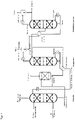
- FIG. 1 A preferred embodiment of such a device is in figure 1 pictured.
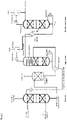
- FIG 2 shows a preferred embodiment in which the regenerator additionally comprises a backwash zone.
- the absorber is preferably designed as an absorption column or absorption tower.
- the absorption column preferably has an absorption zone.
- the absorption zone is considered to be the section of an absorption column in which the fluid stream comes into mass transfer contact with the absorbent.
- the absorption zone preferably contains internals, for example random packings, packings and/or trays.
- the absorption zone is preferably divided into two to four packing sections which are arranged one above the other and are separated from one another by carrying and holding trays and/or a distribution tray.
- the height of the packings/fillers in the absorption zone is preferably in the range from 5 to 20 m, more preferably in the range from 6 to 15 m and most preferably in the range from 8 to 14 m. If the absorption zone contains soil , the number of trays in the absorption zone is preferably in the range from 8 to 30, more preferably from 12 to 25 and most preferably from 15 to 23 trays.
- an inlet for the fluid flow to be deacidified.
- the absorption zone preferably at the top of the absorption column, there is preferably a take-off point for the deacidified fluid stream.
- a demister is preferably installed in the area where the deacidified fluid flow is taken off.
- the absorber comprises an additional backwash zone above the absorption zone.
- the backwash zone is generally a section of the absorber designed as a reinforcement part, which is arranged above the inlet point for the absorbent.
- the backwash zone preferably has random packings, packings and/or trays in order to intensify the contact of the fluid flow with the washing liquid.
- the backwash zone has trays, in particular valve trays, bubble-cap trays, Thormann trays or sieve trays.
- a feed point for detergent is preferably located above the backwash zone.
- the backwash zone preferably comprises 1 to 7, particularly preferably 2 to 6, and very particularly preferably 3 to 5 trays, or a packing height (packing or packing) of preferably 1 to 6 m, particularly preferably 2 to 5 and very particularly preferably 2 to 3 m.
- a collecting tray can be arranged, on which washing liquid can be collected and recycled. The recycling usually takes place via a pump that pumps the washing liquid from the collecting tray to the inflow point. In the case of recycling, the washing liquid can be cooled using a heat exchanger.
- the liquid outlet of the absorber is preferably connected via a heat exchanger to the regenerator b) via pipelines.
- the heat exchanger can be designed as a plate heat exchanger or tube bundle heat exchanger.
- the bottom stream from the regenerator b) is preferably used as the heating medium of the heat exchanger.
- the regenerator comprises a regeneration zone, an evaporator, an inlet for the loaded absorbent, a liquid outlet in the bottom of the regenerator and an outlet in the top region of the regenerator
- the region of the regenerator in which the loaded absorbent comes into contact with the vapor that is generated by the bottom evaporator is regarded as the regeneration zone.
- the regeneration zone preferably contains internals such as random packings, packing and/or trays.
- the regeneration zone is preferably divided into two to four packing sections which are arranged one above the other and are separated from one another by carrying and holding trays and/or a distribution tray.
- the height of the packings/packings in the regeneration zone is preferably in the range from 5 to 15 m, more preferably in the range from 6 to 12 m and most preferably in the range from 8 to 12 m Floors, the number of floors in the regeneration zone is preferably in the range from 10 to 30, particularly preferably 15 to 25 and very particularly preferably 17 to 23 floors.
- the inlet for the loaded absorbent is generally located above or in the upper region of the regeneration zone.
- the regenerator also includes an evaporator.
- the evaporator is preferably a reboiler, natural circulation evaporator or forced circulation evaporator.
- the evaporator is preferably connected to a liquid draw at the bottom of the regenerator via a pipe.
- the area below the regeneration zone is generally referred to as sump.
- the vapor-liquid mixture produced in the evaporator is preferably fed into the lower region of the regenerator via a feed point above the liquid outlet at the bottom, but below the regeneration zone.
- the sump of the regenerator is divided by a collection tray.
- the absorbent collected there is fed to the heat exchanger.
- the steam is fed in and the liquid is returned below the collection tray.
- the regenerator also includes a withdrawal point for the gaseous stream produced during regeneration.
- the outlet point for the gaseous stream produced during the regeneration is preferably arranged in the head area of the regenerator.
- a demister is preferably located in the area of the extraction point.
- the regenerator further comprises a backwash zone.
- the backwash zone is generally designed as a reinforcement part of the regenerator section, which is arranged above the regeneration zone or the feed point for the loaded absorbent.
- the backwash zone preferably contains internals such as random packings, packings and/or trays.
- the washing section particularly preferably contains trays such as valve, bubble-cap, Thormann or sieve trays.
- the backwash zone preferably has 1 to 10 trays, particularly preferably 2 to 7 trays and very particularly preferably 2 to 6 trays.
- the height of the internals is preferably in the range from 1 to 10 m, very particularly preferably 2 to 8 m and particularly preferably 3 to 6 m.
- An inlet for washing liquid is preferably located above or in the upper region of the backwash zone.
- the outlet for the gaseous stream produced during regeneration is connected to a head condenser.
- the top condenser includes a gas vent and a condensate drain.
- condensers with cooling coils or helical tubes, double-tube coolers and tube bundle heat exchangers can be used as condensers.
- the device according to the invention comprises at least two condensers, each with a gas outlet and a condensate outlet, the first condenser preferably being cooled with air or cooling water and the second condenser preferably being cooled with a coolant.
- This embodiment has the advantage that the methanol content in the acidic waste gas can be reduced since more methanol can be condensed out. As a result, the methanol recovery rate can be increased, for example to more than 80%, based on the methanol introduced into the process.
- the device according to the invention also comprises a distillation column, comprising a condenser, an evaporator, an inlet for the condensate outlet of the top condenser, a vapor outlet in the top region of the column and a liquid outlet at the bottom of the distillation column.
- the distillation column is preferably configured as a bubble-cap tray column, sieve-tray column or preferably as a column with random or structured packings.
- the internals can be present in one or more beds.
- the rectification column preferably contains 3 to 25 plates, particularly preferably 5 to 20 plates and very particularly preferably 7 to 15 plates.
- the feed for the condensate discharge from the top condenser is preferably located in a spatial area between 25% and 95% of the plates of the rectification column (counted from below), particularly preferably in a spatial area between 40% and 60% of the plates of the rectification column.
- the feeding can take place in the middle of the separating stages.
- a liquid take-off is preferably located at the bottom of the distillation column.
- the liquid take-off is preferably connected to an evaporator via a pipe.
- the evaporator is preferably a reboiler, natural circulation evaporator or forced circulation evaporator.
- the vapor-liquid mixture produced in the evaporator is preferably introduced into the bottom of the distillation column via a vapor feed.
- the vapor outlet is preferably in the top region of the rectification column.
- the vapors produced during the distillation are routed to a top condenser via a pipeline.
- the top condenser usually includes a heat exchanger and a vessel in which the liquid phase can be separated from the gas phase.
- condensers with cooling coils or helical tubes, double-tube coolers and tube bundle heat exchangers can be used as condensers.
- a condensate which mainly contains methanol, usually occurs in the condenser. More than 50% by volume, more preferably more than 65% by volume and more preferably more than 80% by volume of the condensate obtained at the condenser is preferably returned to the top of the rectification column via a pipeline.
- the condensate that is not recycled can be discharged from the process via a pipeline and used again as an inhibitor to prevent hydrate formation at low temperatures.
- the regenerator has an inlet which is connected to the liquid outlet at the bottom of the distillation column.
- the feed point is preferably located above or in the upper region of the regeneration zone.
- the feed point is preferably located above or in the upper region of the washing zone.
- a heat exchanger is arranged between the liquid takeoff at the bottom of distillation column c) and the feed to the regenerator.
- the bottom discharge from the distillation column c) is used as heating medium for the condensate discharge from the top condenser of the regenerator, before the condensate discharge is introduced into the distillation column c).
- the device according to the invention comprises an expansion tank.
- the expansion tank is connected to the absorber a) and the regenerator b).
- the liquid withdrawal from the bottom of the absorber is preferably connected to the expansion tank via a valve.
- the flash tank At least part of the acidic gases of the loaded absorbent is converted into the gas phase and separated from the non-evaporated liquid phase.
- the gas phase is usually drawn off in the upper area of the expansion tank as acidic waste gas and discharged from the process.
- the expansion tank In the lower area of the expansion tank there is preferably a liquid outlet for the non-evaporated liquid phase, which is connected to the regenerator via a pipeline.
- the feed point for the liquid phase from the expansion tank is preferably located above the regeneration zone.
- a heat exchanger which is operated with the bottom discharge of the regenerator as the heating medium, is particularly preferably arranged between the expansion tank and the regenerator.
- the present invention further relates to the use of the device according to the invention and one of its preferred embodiments, or combinations of the preferred embodiments, for the production of deacidified natural gas with a low methanol content.
- a device can be used in particular in countries and regions in which the climatic conditions require inhibition of hydrate formation with methanol.
- the device can be used according to the method conditions described above.
- the device according to the invention has the advantage over the introduction into the absorber known from the prior art that the bottom stream from stage e) has a may have a higher residual methanol content.
- the rectification column can be constructed with fewer separation stages or be operated with a low evaporator output. As a result, operating costs and/or investment costs can be reduced.
- the process according to the invention also has the advantage that the methanol fed in as an inhibitor can be recovered at a high rate, preferably more than 80%, based on the methanol fed in. This further reduces the operating costs of the overall process.
- the regenerated absorbent thus has such a low content of methanol that the methanol, which is introduced in step a) with the fluid stream to be deacidified, can be almost completely removed. In this way, recycle streams can be used optimally and the supply of components of the absorbent to compensate for losses can be reduced.
- the removal of the methanol from the deacidified fluid stream has the advantage that the problems occurring in the presence of methanol can be reduced in subsequent work-up steps.
- the subsequent dewatering is designed as a PSA or TSA, for example, in which a molecular sieve is used as the solid desiccant
- a 3 A molecular sieve can be used instead of a 4 A molecular sieve, since the adsorption of water does not compete with the adsorption of methanol. As a result, other components such as H 2 S and ethane are not absorbed either. This enables a smaller design of the dewatering stage.
- a lower methanol content leads to less coking of the molecular sieve.
- TEG triethylene glycol
- the invention is illustrated by the following examples: The examples are based on calculations that were carried out using a simulation model.
- a model by Pitzer KS Pitzer, Activity Coefficients in Electrolyte Solutions 2nd ed., CRC Press, 1991, Chapter 3, Ion Interaction Approach: Theory ) used.
- the simulation of the absorption processes is described using a mass transfer-based approach; Details are available from Asprion ( Asprion, N.: Nonequilibrium Rate-Based Simulation of Reactive Systems: Simulation Model, Heat Transfer, and Influence of Film Discretization, Ind. Eng. Chem. Res. (2006) 45(6), 2054-2069 ) described.
- the distillation column was designed using a thermodynamic model based on the NRTL approach to describe the vapor-liquid equilibrium of water-methanol.
- Nm3/h stands for the volume flow specified in standard cubic meters per hour.
- the standard cubic meter relates to a temperature of 273.15 K and a pressure of 1.01325 bar. All data in the unit “% by volume” also relate to these conditions.
- a process is simulated in a plant according to figure 1 .
- the process consists of an absorption column, a flash tank (HP flash), a regenerator with an evaporator and head condenser.
- the liquid stream (methanol+water) condensed out in the top condenser is fed into a further column via a heat exchanger.
- methanol (top product) and water (bottom product) are separated by distillation.
- the bottoms product is returned to the top of the regenerator.
- the reflux ratio v of the distillation column is 7.5
- the methanol recovery is 90% based on the amount of fluid stream introduced in step a).
- a process is simulated in a plant according to figure 2 .
- the configuration largely corresponds to example 1, with the difference that a backwash section with three trays was also taken into account in the regenerator.
Landscapes
- Chemical & Material Sciences (AREA)
- Oil, Petroleum & Natural Gas (AREA)
- Chemical Kinetics & Catalysis (AREA)
- Engineering & Computer Science (AREA)
- General Chemical & Material Sciences (AREA)
- Analytical Chemistry (AREA)
- Organic Chemistry (AREA)
- Gas Separation By Absorption (AREA)
Description
- Die vorliegende Erfindung betrifft ein Verfahren zur Herstellung eines entsäuerten Fluidstroms, insbesondere zur Herstellung von entsäuertem Erdgas, mit einem geringen Methanolgehalt. Weiterhin betrifft die vorliegende Anmeldung eine Vorrichtung zur Entsäuerung eines Methanolhaltigen Fluidstroms, sowie deren Verwendung.
- Die Entfernung der sauren Gase aus Fluidströmen ist aus verschiedenen Gründen wünschenswert.
- Erdgas, welches nach der Förderung anfällt, enthält neben Methan verschiedene andere Komponenten, wie weitere Kohlenwasserstoffe, Wasser, sowie saure Gase, wie CO2, H2S oder Mercaptane.
- Roherdgas muss vor dem Verkauf als sogenanntes Sales Gas oder Verkaufsgas aufgereinigt werden, damit es den Spezifikationen und Anforderungen der Kunden und der Vertriebsgesellschaften genügt.
- So muss beispielsweise Wasser aus Erdgas weitestgehend entfernt werden, da es bei ungenügender Trocknung des Erdgases zur Bildung von Methanhydraten kommen kann. Die festen Methanhydrate können zu einem extremen Druckabfall in den Förderleitungen beitragen und die Ventile und Rohrleitungen verstopfen oder sogar beschädigen.
- Die Trocknung garantiert auch einen gleichbleibenden Brennwert des Gases bei der Einspeisung in das öffentliche Gasnetz.
- Zudem müssen saure Gase, wie CO2, H2S und Mercaptane, entfernt werden, da sie korrosiv sind und zu Korrosionsschäden in den Rohrleitungen oder Apparaten der Roherdgas-Aufarbeitungsanlagen führen können. Zudem sind sie, wie CO2 und H2S Umweltschadstoffe, die wesentliche Verursacher von sogenannten sauren Regen sind.
- Bei der Herstellung von Flüssigerdgas (Liquid Natural Gas = LNG) ist vor der Verflüssigung eine Aufreinigung des Roherdgases notwendig, u.a. muss CO2 bis auf 50 vppm abgetrennt werden, um nicht in der Verflüssigung als Feststoff auszufallen.
- Das Roherdgas durchläuft deshalb in der Regel eine Vielzahl von Reinigungsschritten, bevor es als Verkaufsgas in das Erdgasnetz eingespeist wird.
- Üblicherweise wird zunächst ein Großteil des enthaltenen Wassers und Erdgaskondensat abgetrennt. Hierbei wird das Roherdgas in der Regel gekühlt, so dass Wasser und die Bestandteile, die das Erdgaskondensat bilden, wie längerkettige Alkane und Aromate, auskondensieren. Die auskondensierten Flüssigkeiten, d.h. das Erdgaskondensat und Wasser, können vom nichtverflüssigten Erdgas abgetrennt werden. Die Abtrennung von Wasser und Erdgaskondensat erfolgt in der Regel am oder in der Nähe der Förderstätte.
- In kälteren Erdregionen wird dem Erdgas vor dem Transport zu einer Erdgas-Verarbeitungsanlage oder auch vor der Entfernung der sauren Gasen üblicherweise Methanol zugesetzt. Methanol wirkt als Inhibitor gegen die Bildung von Methanhydraten im Roherdgas. Die Zugabe von Methanol zum Roherdgas ermöglicht somit den Transport des Roherdgases von der Förderstätte zur Erdgas-Verarbeitungsanlage bei kalten Außentemperaturen.
- Die Zugabe von Methanol zum Roherdgas kann aber in den nachfolgenden Aufarbeitungsschritten in einer Erdgas-Verarbeitungsanlage zu Problemen führen.
- Eine Erdgas-Verarbeitungsanlage umfasst im Allgemeinen einen oder mehreren der folgenden Schritte:
- (i) Entsäuerung;
- (ii) Entwässerung;
- (iii) Entfernung von Quecksilber;
- (iv) Entfernung von Stickstoff;
- (v) Entfernung von Erdgaskondensaten; und/oder
- (vi) Verflüssigung zur Herstellung von LNG
- Im Entsäuerungsschritt (i) wird das Roherdgas im Allgemeinen mit einem Absorptionsmittel in Kontakt gebracht, welches zumindest einen Teil der sauren Gase absorbiert, so dass ein entsäuertes Erdgas und ein mit den sauren Gasen beladenes Absorptionsmittel erhalten wird. Im Entsäuerungsschritt (i) wird das im Roherdgas vorhandene Methanol in der Regel nicht vollständig im Absorptionsmittel co-absorbiert, so dass das entsäuerte Erdgas noch gewisse Restmengen an Methanol enthält, bevor es der Entwässerungsstufe (ii) zugeführt wird. Dies kann insbesondere der Fall sein, wenn das Absorptionsmittel selber Restmengen von Methanol enthält. Restmengen von Methanol können im Absorptionsmittel enthalten sein, wenn regeneriertes Absorptionsmittel zur Entsäuerung eingesetzt wird, aus dem Methanol nicht vollständig entfernt wurde.
- Restmengen von Methanol können jedoch in der nachfolgenden Entwässerungsstufe (ii) zu Problemen führen.
- Die Entwässerung kann beispielsweise als Druckwechsel-Adsorption (oder Pressure Swing Adsorption (PSA)), bevorzugt als Temperaturwechsel-Adsorption (TSA) oder als GlykolTrocknung ausgestaltet sein.
- Ist die Entwässerung (ii) beispielsweise als PSA bzw. TSA ausgestaltet, in der ein Molsieb als festes Trocknungsmittel eingesetzt wird, so muss bei der Anwesenheit von Restmengen an Methanol ein 4 A Molsieb anstelle eines 3 A Molsiebs verwendet werden, wodurch neben Wasser und Methanol auch weitere Komponenten, wie H2S und Ethan absorbiert werden. Zusätzlich steht die Absorption von Methanol in Konkurrenz zu der bevorzugten Absorption von Wasser. Die Co-Absorption von Methan und anderen Bestandteilen durch Verwendung eines größeren Molsiebs erfordert, dass der Adsorber größer ausgelegt werden muss. Methanol kann darüber hinaus bei der Regeneration der Molsiebs durch Temperaturerhöhung zu einer schnelleren Verkokung des Molsiebes führen.
- Sowohl bei einer Adsorptionseinheit auf Basis des PSA- bzw. TSA-Verfahrens, als auch bei einer Entwässerungseinheit auf Basis der sogenannten Glykol-Entwässerung kann es zur Verschleppung von Methanol über mehrere Anlagenteile kommen, da das bei der Regeneration des Trocknungsmittels abgetrennte Wasser zusätzlich Methanol enthält.
- Die Anwesenheit von Methanol erfordert im Allgemeinen eine weitere Nachbehandlung des abgetrennten Wassers, bei der Methanol von Wasser abgetrennt wird, um Methanol und/oder Wasser in einer Reinheit zurückzugewinnen, in der die Stoffe wieder als Make-Up-Wasser bzw. Inhibitor wiederverwendet werden können.
- Die
RU 2602908 - Bei diesem Verfahren wird das MeOH-haltige Roherdgas zunächst in einen Absorber eingeleitet. In dem Absorber wird das MeOH-haltige Roherdgas mit einer wässrigen Aminlösung in Kontakt gebracht. Hierbei wird neben den sauren Gasen, wie CO2, auch der überwiegende Teil des MeOH absorbiert. In einem Regenerator wird die beladene Aminlösung bei höheren Temperaturen regeneriert, wobei die sauren Gase und MeOH aus der beladenen Aminlösung rausgestrippt werden. Der über den Kopf des Regenerators erhaltene Strom wird einem Kondensator zugeführt, in dem der überwiegende Anteil an Methanol zusammen mit dem Strippdampf auskondensiert wird und von den in der Gasphase verbleibenden sauren Gasen abgetrennt wird. Die
RU 2602908 - Nachteilig bei dem in der
RU 2602908 - Bei der Herstellung von Synthesegas können sich ähnliche Probleme ergeben. So kann bei der Herstellung von Synthesegas durch Dampfreformierung von Methan Methanol als Nebenprodukt gebildet werden. Im Fluidstrom kann somit neben Wasserstoff und sauren Gasen, wie CO2 und CO, auch noch Methanol vorhanden sein. Nach der Abtrennung von mindestens eines Teils der sauren Gase durch Sauergaswäsche kann das entsäuerte Synthesegas und/oder der entsäuerte Wasserstoff auch Restmengen von Methanol enthalten. Zusammen mit Wasser, welches im Allgemeinen durch ein wässriges Absorptionsmittel eingetragen werden kann, kann es bei der nachfolgenden Trocknung des Synthesegases und/oder Wasserstoffs ebenfalls zu den oben beschriebenen Problemen kommen.
- Die Aufgabe der vorliegenden Erfindung bestand deshalb darin, einen entsäuerten Fluidstrom, insbesondere ein entsäuertes Erdgas, zu erzeugen, welches einen geringen MeOH-Gehalt aufweist, wobei das hierfür erforderliche Herstellverfahren geringere Investitions- und Betriebskosten aufweisen sollte.
- Insbesondere sollte durch die vorliegende Erfindung eine hohe Rückgewinnungsquote des als Inhibitor eingesetzten Methanols ermöglicht werden.
- Zudem sollte es ermöglicht werden, die Mengen an Bestandteilen des Absorptionsmittels, wie Wasser, die zugeführt werden müssen um eventuelle Verluste im Verfahren auszugleichen, zu verringern. Aus diesen Grund sollte das erfindungsgemäße Verfahren die Rückführung von Strömen aus bestimmten Verfahrensschritte in andere Verfahrensschritte ermöglichen.
- Die Aufgabe der vorliegenden Erfindung wurde gelöst durch ein
- Verfahren zur Herstellung eines entsäuerten Fluidstroms aus einem Fluidstrom, enthaltend Methanol und mindestens ein saures Gas, umfassend
- a) einen Absorptionsschritt, bei dem man den Fluidstrom mit einem Absorptionsmittel in einem Absorber in Kontakt bringt, wobei man ein mit Methanol und sauren Gasen beladenes Absorptionsmittel und einen zumindest teilweise entsäuerten Fluidstrom erhält;
- b) einen Regenerationsschritt, bei dem man zumindest ein Teil des aus Schritt a) erhaltenen, beladenen Absorptionsmittel in einem Regenerator regeneriert, wobei man ein zumindest teilweise regeneriertes Absorptionsmittel und einen gasförmigen Strom enthaltend Methanol, Wasser und mindestens ein saures Gas erhält;
- c) einen Rückführschritt, bei dem man zumindest einen Teilstrom des regenerierten Absorptionsmittels aus Schritt b) in den Absorptionsschritt a) zurückführt,
- d) einem Kondensationsschritt, bei dem man ein Kondensat, enthaltend Methanol und Wasser, aus dem gasförmigen Stroms aus Schritt b) auskondensiert;
- e) einem Destillationsschritt, bei dem man zumindest einen Teil des Kondensats aus Schritt d) in eine Destillationskolonne leitet, wobei man einen Kopfstrom, enthaltend Methanol, und einen Sumpfstrom, enthaltend Wasser, erhält;
- In das erfindungsgemäße Verfahren wird ein Fluidstrom, enthaltend Methanol und mindestens einem sauren Gas eingesetzt.
- Die Menge an Methanol im Fluidstrom liegt bevorzugt im Bereich von 50 bis 5000 vppm, besonders bevorzugt 100 bis 1000 vppm und ganz besonders bevorzugt 200 bis 800 vppm.
- Das Methanol wird dem Fluidstrom bevorzugt vor Schritt a) zugegeben. Methanol kann aber auch vor Schritt a) als Nebenprodukt bei der Herstellung des Fluidstroms gebildet werden, beispielsweise bei der Dampfreformierung von Methan.
- Weiterhin enthält der eingesetzte Fluidstrom mindestens ein saures Gas. Bevorzugt enthält das Roherdgas CO2 und/oder H2S. Neben CO2 und/oder H2S können andere saure Gase im Roherdgas vorhanden sein, wie COS und Mercaptane. Außerdem können auch SO3, SO2, CS2 und HCN enthalten sein.
- Der Gehalt an sauren Gasen im Fluidstrom beträgt im Allgemeinen 0,01 bis 40 Vol.%, bevorzugt 0,05 bis 15 Vol.-% und besonders bevorzugt 0,1 bis 5 Vol.%.
- Der in das erfindungsgemäße Verfahren eingesetzte Fluidstrom kann zudem Wasser enthalten.
- Der Wassergehalt im Fluidstrom liegt im Allgemeinen in einem Bereich von >0 Vol.-% bis zu einem Gehalt, der der Sättigungskonzentration von Wasser in dem Fluidstrom bei den vorliegenden Druck- und Temperaturbedingungen entspricht.
- In einer bevorzugten Ausführungsform enthält der eingesetzte Fluidstrom Kohlenwasserstoffe. Der Kohlenwasserstoffgehalt im Fluidstrom beträgt im Allgemeinen 60 bis 99,9 Vol-%, bevorzugt 85 bis 99,5 Vol.-% und besonders bevorzugt 95 bis 99 Vol.%.
- Die im Fluidstrom enthaltenden Kohlenwasserstoffe enthalten bevorzugt 80 bis 100 Vol.-% Methan, besonders bevorzugt 90 bis 99,9 Vol.-% und ganz besonders bevorzugt 95 bis 99 Vol.-% Methan.
- Der Fluidstrom kann neben Methan und sauren Gasen weitere Komponenten enthalten, wie andere Gase (N2 oder He), Quecksilber oder natürlich vorkommenden radioaktiven Substanzen.
- Der Anteil an weiteren Komponenten im Fluidstrom beträgt im Allgemeinen 0 bis 4 Vol.-%, bevorzugt 0,0001 bis 3, Vol.-% und ganz besonders bevorzugt 0,0005 bis 1,5 Vol.-%.
- Der Fluidstrom kann jeder Fluidstrom sein, der mindestens ein saures Gas und Methanol enthält. Der Fluidstrom ist bevorzugt Roherdgas. Der Fluidstrom kann aber auch ein Synthesegas oder ein Biogas sein, zu welchem Methanol zugegeben wurde oder bei dessen Herstellung Methanol als Nebenprodukt entsteht. Als Roherdgas wird in der Regel ein Roherdgas eingesetzt, von dem Erdgaskondensat und Wasser durch Auskondensation abgetrennt wurden. Die Abtrennung von Erdgaskondensat und Wasser kann nach einem dem Fachmann bekannten Verfahren erfolgen, beispielsweise in dem man die Temperatur des geförderten Roherdgas erniedrigt und die auskondensierten Bestandteile, wie Wasser und das Erdgaskondensat, von den nichtkondensierten Bestandteilen des Roherdgases abtrennt
- Bevorzugt wird ein Fluidstrom eingesetzt, welcher einen Gesamtdruck im Bereich von 20 bis 120 bar, besonders bevorzugt 40 bis 100 bar und ganz besonders bevorzugt 50 bis 80 bar aufweist.
- Der Fluidstrom wird erfindungsgemäß in einen Absorptionsschritt eingeleitet, bei dem man den Fluidstrom mit einem Absorptionsmittel in einem Absorber in Kontakt bringt, wobei man ein mit Methanol und sauren Gasen beladenes Absorptionsmittel und einen zumindest teilweise entsäuerten Fluidstrom erhält.
- Das Absorptionsmittel enthält mindestens ein Amin.
- Bevorzugte Amine sind die folgenden:
- i) Amine der Formel I:
NR1(R2)2 (I)
worin R1 unter C2-C6-Hydroxyalkylgruppen, C1-C6-Alkoxy-C2-C6-alkylgruppen, Hydroxy- C1-C6-Alkoxy-C2-C6-alkylgruppen und 1-Piperazinyl-C2-C6-alkylgruppen ausgewählt ist und R2 unabhängig unter H, C1-C6-Alkylgruppen und C2-C6-Hydroxyalkylgruppen ausgewählt ist; - ii) Amine der Formel II:
R3R4N-X-NR5R6 (II)
worin R3, R4, R5 und R6 unabhängig voneinander unter H, C1-C6-Alkylgruppen, C2-C6- Hydroxyalkylgruppen, C1-C6-Alkoxy-C2-C6-alkylgruppen und C2-C6-Aminoalkylgruppen ausgewählt sind und X für eine C2-C6-Alkylengruppe, -X1-NR7-X2- oder -X1-O-X2- steht, worin X1 und X2 unabhängig voneinander für C2-C6-Alkylengruppen stehen und R7 für H, eine C1-C6-Alkylgruppe, C2-C6-Hydroxyalkylgruppe oder C2-C6-Aminoalkylgruppe steht; - iii) 5- bis 7-gliedrige gesättigte Heterocyclen mit wenigstens einem Stickstoffatom im Ring, die ein oder zwei weitere, unter Stickstoff und Sauerstoff ausgewählte Heteroatome im Ring enthalten können, und
- iv) Gemische davon.
- Spezifische Beispiele für bevorzugt einsetzbare Amine sind:
- i) 2-Aminoethanol (Monoethanolamin), 2-(Methylamino)ethanol, 2-(Ethylamino)- ethanol, 2-(n-Butylamino)ethanol, 2-Amino-2-methylpropanol, N-(2-Aminoethyl)- piperazin, Methyldiethanolamin, Ethyldiethanolamin, Diemthylaminopropanol, t-Butylaminoethoxyethanol (TBAEE), 2-Amino-2-methylpropanol, Diisoproanolamin (DIPA);
- ii) 3-Methylaminopropylamin, Ethylendiamin, Diethylentriamin, Triethylentetramin, 2,2-Dimethyl-1,3-diaminopropan, Hexamethylendiamin, 1,4-Diaminobutan, 3,3- Iminobispropylamin, Tris(2-aminoethyl)amin, Bis(3-dimethylamino-propyl)amin, Tetramethylhexamethylendiamin;
- iii) Piperazin, 2-Methylpiperazin, N-Methylpiperazin, 1-Hydroxyethyl-piperazin, 1,4- Bishydroxyethyl-piperazin, 4-Hydroxyethyl-piperidin, Homopiperazin, Piperidin, 2- Hydroxyethyl-piperidin und Morpholin; und
- iv) Gemische davon.
- In einer bevorzugten Ausführungsform enthält das Absorptionsmittel mindestens eines der Amine Monoethanolamin (MEA), Methylaminopropylamin (MAPA), Piperazin (PIP), Diethanolamin (DEA), Triethanolamin (TEA), Diethylethanolamin (DEEA), Diisopropanolamin (DIPA), Aminoethoxyethanol (AEE), tert.-Butylaminoethoxyethanol (TBAEE Dimethylaminopropanol (DIMAP) und Methyldiethanolamin (MDEA) oder Gemische davon.
- Weitere Amine, die in das Verfahren eingesetzt werden können sind tert.-Butylaminopropandiol, tert.-Butylaminoethoxyethylmorpholin, tert.-Butylaminoethylmorpholin, Methoxyethoxyethoxyethyl-tert.-butylamin, tert-butylaminoethylpyrrolidon, Vorzugsweise ist das Amin ein sterisch gehindertes Amin oder ein tertiäres Amin. Ein sterisch gehindertes Amin ist ein sekundäres Amin, in dem der Amin-Stickstoff an mindestens ein sekundäres Kohlenstoffatom und/oder mindestens ein tertiäres Kohlenstoffatom gebunden ist; oder ein primäres Amin, in dem der Amin-Stickstoff an ein tertiäres Kohlenstoffatom gebunden ist. Ein bevorzugtes sterisch gehindertes Amin ist t-Butylaminoethoxyethanol. Ein bevorzugtes tertiäres Amin ist Methyldiethanolamin.
- Wird angestrebt das im Fluidstrom enthaltenden CO2 vollständig oder nahezu vollständig zu entfernen, so enthält das Absorptionsmittel bevorzugt zudem einen Aktivator, wenn das im Absorptionsmittel enthaltende Amin ein sterisch gehindertes Amin oder ein tertiäres Amin ist. Der Aktivator ist im Allgemeinen ein sterisch ungehindertes primäres oder sekundäres Amin. In diesen sterisch ungehinderten Aminen ist der Amin-Stickstoff mindestens einer Aminogruppe nur an primäre Kohlenstoffatome und Wasserstoffatome gebunden. Wird lediglich angestrebt einen Teil der im Fluidstrom enthaltenden Gase zu entfernen, beispielsweise die selektive Entfernung von H2S aus einem Fluidstrom enthaltend H2S und CO2, so enthält das Absorptionsmittel bevorzugt keinen Aktivator.
- Das sterisch ungehinderte primäre oder sekundäre Amin welches als Aktivator eingesetzt werden kann ist beispielsweise ausgewählt unter Alkanolaminen, wie Monoethanolamin (MEA), Diethanolamin, (DEA), Ethylaminoethanol, 1-Amino-2-methyl-propan-2-ol, 2-Amino-1-butanol, 2-(2-Aminoethoxy)ethanol und 2-(2-Aminoethoxy)ethanamin, Polyaminen, wie Hexamethylendiamin, 1,4-Diaminobutan, 1,3-Diaminopropan, 3-(Methylamino)propylamin (MAPA), N-(2-Hydroxyethyl)ethylendiamin, 3-(Dimethylamino)propylamin (DMAPA), 3-(Diethylamino)propylamin, N,N'-Bis(2- hydroxyethyl)ethylendiamin, 5-, 6- oder 7-gliedrigen gesättigten Heterocyclen mit wenigstens einer NH-Gruppe im Ring, die ein oder zwei weitere, unter Stickstoff und Sauerstoff ausgewählte Heteroatome im Ring enthalten können, wie Piperazin, 2-Methylpiperazin, N-Methylpiperazin, N-Ethylpiperazin, N-(2-Hydroxyethyl)piperazin, N-(2-Aminoethyl)piperazin, Homopiperazin, Piperidin und Morpholin.
- Besonders bevorzugt sind 5-, 6- oder 7-gliedrige gesättigte Heterocyclen mit wenigstens einer NH-Gruppe im Ring, die ein oder zwei weitere, unter Stickstoff und Sauerstoff ausgewählte Heteroatome im Ring enthalten können. Ganz besonders bevorzugt ist Piperazin.
- In einer Ausführungsform enthält das Absorptionsmittel das tertiäre Amin Methyldiethanolamin und den Aktivator Piperazin.
- Das molare Verhältnis von Aktivator zu sterisch gehindertem Amin oder tertiärem Amin liegt bevorzugt im Bereich von 0,05 bis 1,0, besonders bevorzugt im Bereich von 0,05 bis 0,7. Im Allgemeinen enthält das Absorptionsmittel 10 bis 60 Gew.-% Amin.
- Das Absorptionsmittel kann zusätzlich noch physikalische Lösungsmittel enthalten. Geeignete physikalische Lösungsmittel sind beispielsweise N-Methylpyrrolidon, Tetramethylensulfon, Oligoethylenglykoldialkylether wie Oligoethylenglykolmethylisopropylether (SEPASOLV MPE), Oligoethylenglykoldimethylether (SELEXOL). Das physikalische Lösungsmittel ist im Absorptionsmittel im Allgemeinen in Mengen von 1 bis 60 Gew.-%, vorzugsweise 10 bis 50 Gew.-%, insbesondere 20 bis 40 Gew.- %, enthalten.
- Das Absorptionsmittel enthält in einer bevorzugten Ausführungsform weniger als 10 Gew.-%, z.B. weniger als 5 Gew.-%, insbesondere weniger als 2 Gew.-% anorganische basische Salze, wie z.B. Kaliumcarbonat.
- Das Absorptionsmittel kann auch Additive, wie Korrosionsinhibitoren, Antioxidantien, Enzyme, Antischaummittel etc. enthalten. Im Allgemeinen liegt die Menge an derartigen Additiven im Bereich von etwa 0,01-3 Gew.-% des Absorptionsmittels.
- Dem Absorber kann frisches Absorptionsmittel zugeführt werden, oder dem Absorber kann in den Rückführschritt e) regeneriertes Absorptionsmittel zugeführt werden. Die Zuführung von frischem Absorptionsmittel bedeutet, dass die Komponenten des Absorptionsmittels die Schritte b) bis e) noch nicht durchlaufen haben. Die Zuführung von regeneriertem Absorptionsmittel erfordert, dass zumindest ein Teil der Komponenten des Absorptionsmittels die Schritte b) bis e) durchlaufen haben.
- Das Absorptionsmittel enthält bevorzugt 0,05 Vol.-% oder weniger Methanol, besonders bevorzugt 0,03 Vol.-% oder weniger Methanol, ganz besonders bevorzugt 0,01 Vol.-% oder weniger Methanol und insbesondere 0,005 Vol.-% oder weniger Methanol.
- Das Absorptionsmittel ist vorzugsweise wässrig. D.h. dass die verschiedenen Bestanteile des Absorptionsmittels, wie Amin, Methanol, physikalische Lösungsmittel, Additiven in den oben genannten Mengen mit Wasser vermischt werden.
- Ganz besonders bevorzugt wird eine wässrige Lösung von Methyldiethanolamin als Absorptionsmittel eingesetzt.
- Das Inkontaktbringen des Fluidstroms mit dem Absorptionsmittel in Schritt a) erfolgt im einem Absorber.
- Der Absorber ist bevorzugt ein Absorptionsturm bzw. eine Absorptionskolonne, z. B. einer Füllkörper-, Packungs- oder Bodenkolonne.
- Der Absorber umfasst im Allgemeinen eine Absorptionszone und optional eine Rückwaschzone.
- Als Absorptionszone wird die Sektion der Absorptionskolonne angesehen, in der der Fluidstrom in Stoffaustausch-Kontakt mit dem Absorptionsmittel kommt.
- Das Inkontaktbringen des Fluidstroms mit dem Absorptionsmittel in der Absorptionszone erfolgt vorzugsweise im Gegenstrom.
- Zur Verbesserung des Kontakts mit dem Absorptionsmittel und Schaffung einer großen Stoffaustauschgrenzfläche enthält die Absorptionszone in der Regel Einbauten, z.B. Füllkörper, Packungen und/oder Böden, wie Ventil-, Glocken-, Thormann- oder Siebböden.
- Enthält die Absorptionszone Füllkörper oder Packungen, liegt die Höhe der Füllkörper/Packungen der Absorptionszone bevorzugt im Bereich von 5 bis 20 m, besonders bevorzugt im Bereich von 6 bis 15 m und ganz besonders bevorzugt im Bereich von 8 bis14 m. Enthält die Absorptionszone Böden, so liegt die Bodenanzahl der Absorptionszone vorzugsweise im Bereich von 8 bis 30, besonders bevorzugt 12 bis 25 und ganz besonders bevorzugt 15 bis 23 Böden.
- Bei Füllkörper- bzw. Packungskolonnen kann die Absorptionszone in ein oder mehrere Abschnitte, bevorzugt 2 bis 4 Abschnitte, unterteilt sein. Zwischen den einzelnen Abschnitten der Absorptionszone können Trag- und Halteböden und/oder Verteilerböden angeordnet sein, die die Verteilung des Absorptionsmittels über den gesamten Kolonnenquerschnitt verbessern.
- Die Temperatur des in die Absorptionszone eingeführten Absorptionsmittels beträgt im Allgemeinen etwa 0 bis 60°C, bevorzugt 10 bis 50°C und besonders bevorzugt 25 bis 50°C.
- Der Druck im Absorber liegt üblicherweise im Bereich von 30 bis 120 bar, besonders bevorzugt 40 bis 100 bar und ganz besonders bevorzugt 50 bis 80 bar aufweist.
- Die Zulaufstelle für den eingeleiteten Fluidstrom befindet sich bevorzugt unterhalb oder im unteren Bereich der Absorptionszone. Vorzugsweise erfolgt der Zulauf über einen Gasverteiler.
- Der Absorber kann ein oder mehrere Zulaufstellen für das eingeleitete Absorptionsmittel umfassen. So kann der Absorber eine Zulaufstelle für frisches Absorptionsmittel und eine Zulaufstelle für regeneriertes Absorptionsmittel umfassen. Frisches und regeneriertes Absorptionsmittel können aber auch gemeinsam über eine Zulaufstelle in den Absorber zugeführt werden. Die eine oder mehreren Zulaufstellen befinden sich bevorzugt oberhalb oder im oberen Bereich der Absorptionszone. Über die Zulaufstelle für frisches Absorptionsmittel können auch einzelne Bestandteile des Absorptionsmittels, wie Make-Up-Wasser, zugeführt werden.
- Weist der Absorber eine optionale Rückwaschzone auf, so erfolgt der Zulauf bevorzugt zwischen der Absorberzone und der Rückwaschzone.
- Durch das Inkontaktbringen des Fluidstroms mit dem Absorptionsmittel in der Absorptionszone wird ein zumindest teilweise entsäuerter Fluidstrom und ein mit MeOH und sauren Gasen beladenes Absorptionsmittel erhalten.
- Im oberen Bereich des Absorbers befindet sich in der Regel eine Abzugsstelle für den entsäuerten Fluidstrom. Im Bereich der Abzugsstelle kann ein Demister angebracht sein, um eventuelle Flüssigkeitsreste des Absorptionsmittels oder des Waschmittels aus dem austretenden Fluidstrom abzuscheiden.
- Im unteren Bereich des Absorbers, vorzugsweise am Sumpf, befindet sich im Allgemeinen eine Abzugsstelle für das beladene Absorptionsmittel.
- Der zumindest teilweise entsäuerte Fluidstrom kann in der Absorptionszone optional mit einer Waschflüssigkeit in Kontakt gebracht werden.
- Die Zulaufstelle für das Waschmittel befindet sich bevorzugt im oberen Bereich oder oberhalb der Absorptionszone.
- Besonders bevorzugt ist die Waschflüssigkeit eine wässrige Flüssigkeit. Es kann sich bei der Waschflüssigkeit um eine dem Verfahren intrinsische Flüssigkeit handeln, d.h. eine wässrige Flüssigkeit, die an anderer Stelle des Verfahrens anfällt, oder um von außen zugeführte wässrige Flüssigkeiten. Vorzugsweise umfasst die Waschflüssigkeit ein bei einer stromabwärts erfolgenden Kühlung des entsäuerten Fluidstroms gebildetes Kondensat (sogenanntes Absorberkopfkondensat) und/oder Frischwasser.
- Durch das Inkontaktbringen des zumindest teilweise entsäuerten Fluidstrom mit einer Waschflüssigkeit können mitgeführte Absorptionmittelbestandteile, wie Amine, ausgewaschen werden. Durch das Inkontaktbringen mit einer wässrigen Waschflüssigkeit kann zudem die Wasserbilanz des Verfahrens ausgeglichen werden, wenn über die austretenden Ströme mehr Wasser ausgetragen wird, als über die eintretenden Ströme eingetragen wird.
- Optional kann der Absorber eine sogenannte Rückwaschzone aufweisen. In der Rückwaschzone wird dem entsäuerten Fluidstrom im Allgemeinen eine Waschflüssigkeit im Gegenstrom entgegengeführt.
- Die Rückwaschzone ist in der Regel eine Sektion des Absorbers, der sich oberhalb der Einspeisestelle des Absorptionsmittels befindet.
- Vorzugsweise weist die Rückwaschzone Füllkörper, Packungen und/oder Böden auf, um den Kontakt des Fluidstrom mit der Waschflüssigkeit zu intensivieren. Besonders weist die Rückwaschzone Böden, insbesondere Ventil-, Glocken-, Thormann- oder Siebböden auf.
- Die Rückwaschzone umfasst bevorzugt 1 bis 7, besonders bevorzugt 2 bis 6, und ganz besonders bevorzugt 3 bis 5 Böden, oder eine Packungshöhe (Füllkörper/Packungen) von bevorzugt 1 bis 6 m, besonders bevorzugt 2 bis 5 und ganz besonders bevorzugt 2 bis 3 m.
- Die Waschflüssigkeit wird im Allgemeinen oberhalb der Rückwaschzone oder in den oberen Bereich der Rückwaschzone eingeleitet. Als Waschflüssigkeit können die voranstehend genannten Waschflüssigkeiten eingesetzt werden.
- Man kann die Waschflüssigkeit über die Rückwaschzone recyclieren. Die Waschflüssigkeit wird hierzu unterhalb der Rückwaschzone, z. B. mittels eines geeigneten Sammelbodens, gesammelt und über eine Pumpe zum oberen Ende der Rückwaschzone gepumpt. Man kann die recyclierte Waschflüssigkeit kühlen, vorzugsweise auf eine Temperatur von 20 bis 70 °C, insbesondere 30 bis 60 °C. Hierzu wird die Waschflüssigkeit zweckmäßigerweise über einen Kühler umgepumpt. Um eine Akkumulation ausgewaschener Absorptionsmittelbestandteile in der Waschflüssigkeit zu vermeiden, wird vorzugsweise ein Teilstrom der Waschflüssigkeit aus der Rückwaschzone ausgeleitet.
- Der entsäuerte Fluidstrom wird, wie voranstehend beschrieben, vorzugsweise über einen Abzug im oberen Teil des Absorbers abgezogen.
- Optional kann der entsäuerte Fluidstrom über einen Kondensator geleitet werden.
- Als Kondensator können beispielsweise Kondensatoren mit Kühlschlange oder Wendelrohr, Plattenwärmetausche, Doppelrohrkühler sowie Rohrbündelwärmetauscher eingesetzt werden. Der Kondensator wird im Allgemeinen bei einer Temperatur im Bereich von 10 bis 60°C, bevorzugt 20 bis 50 °C, besonders bevorzugt 20 bis 30 °C betrieben.
- Der entsäuerte Fluidstrom, der in Schritt a) erhalten wird, enthält bevorzugt 0,01 bis 10 vppm Methanol, besonders bevorzugt 0,05 bis 5 vppm Methanol, und ganz besonders bevorzugt 0,1 bis 3 vppm Methanol.
- Der Wassergehalt des entsäuerten Fluidstrom, liegt im Allgemeinen bei 80 - 100 % der Sättigungskonzentration von Wasser in dem Fluidstrom bei den vorliegenden Druck- und Temperaturbedingungen.
- Soll der entsäuerte Fluidstrom als Verkaufsgas (Sales Gas) verwendet werden, so beträgt der Gehalt an H2S im entsäuerten Fluidstrom vorzugsweise 5 vppm oder weniger und der CO2-Gehalt 2 Vol.-% und weniger.
- Soll der entsäuerte Fluidstrom zu LNG verflüssigt werden, so beträgt der CO2-Gehalt im entsäuerten Fluidstrom vorzugsweise 100 vppm und weniger und besonders bevorzugt 50 vppm und weniger. Der H2S-Gehalt im entsäuerten Fluidstrom beträgt bei LNG vorzugsweise 5 vppm und weniger und besonders bevorzugt 2 vppm und weniger.
- An dem entsäuerten Fluidstrom, der in Schritt a) erhalten wird, werden optional im Anschluss ein oder mehrere der folgenden Aufarbeitungsschritte durchgeführt:
- aa) Wasserentfernung;
- bb) Entfernung von Quecksilber;
- cc) Entfernung von Stickstoff;
- dd) Entfernung von Erdgaskondensaten; und/oder
- ee) Verflüssigung (LNG)
- Die Wasserentfernung aa) wird vorzugsweise als Druckwechsel-Adsorption (oder Pressure Swing Adsoprtion (PSA)) und besonders bevorzugt als Temperaturwechsel-Adsorption (oder Temperature Swing Adsorption (TSA)) oder als Glykol-Trocknung durchgeführt.
- Die PSA bzw. TSA kann gemäß dem Fachmann bekannten Verfahren eingesetzt werden. Gängige Durchführungsvarianten sind beispielsweise im Nag, Ashis, "Destillation and Hydrocarbon Processing Practices", PennWell 2016, ISBN 978-1-59370-343-1 oder in A. Terrigeol, GPA Europe, Annual Conference, Berlin, Germany, 23rd-25th May, 2012 (https://www.cecachemicals.com/export/sites/ceca/.content/medias/downloads/products/dtm/mo lecular-sieves-contaminants-effects-consequences-and-mitigation.pdf) beschrieben.
- Bei der PSA bzw. TSA wird vorzugsweise ein Zeolith, Aktivkohle oder Molsieb eingesetzt. Bevorzugt wird in der PSA bzw. TSA ein Molsieb als festes Adsorptionsmittel eingesetzt.
- In der Glykol-Trocknung wird bevorzugt ein flüssiges Absorptionsmittel, wie Monoethylenglykol (MEG), Diethylenglykol (DEG), Triethylenglykol (TEG) oder Tetraethylenglykol (TREG) eingesetzt. Insbesondere bevorzugt wird TEG als flüssiges Absorptionsmittel eingesetzt.
- Die Glykol-Trocknung kann gemäß dem Fachmann bekannten Verfahrensvarianten durchgeführt werden. Beispiele für eine Glykol-Trocknung findet sich beispielsweise ebenfalls in Nag, Ashis""Destillation and Hydrocarbon Processing Practices", PennWell 2016, ISBN 978-1-59370-343-1.
- Im Anschluss an die Trocknung aa) können optional weitere Aufarbeitungsschritte, wie bb) Quecksilber-Entfernung, cc) Entfernung von Stickstoff, dd) Entfernung von Erdgaskondensaten und ee) eine Verflüssigung von Erdgas zu LNG durchgeführt werden. Einzelheiten zu den genannten Verfahrensschritten finden sich ebenfalls in Nag, Ashis "Hydrocarbon Processing Practices".
- Durch die ein oder mehreren Reinigungsschritte aa) bis dd) erhält man in der Regel einen Fluidstrom, der die Spezifikationen von Endkunden und/oder Vertriebsgesellschaften erfüllt und im Falle von Erdgas als sogenanntes Sales Gas verkauft werden kann bzw. in einem weiteren Verflüssigungsschritt ee) zu LNG verflüssigt werden kann.
- In Schritt a) wird zudem ein mit Sauergasen beladenes Absorptionsmittel erhalten.
- Das beladene Absorptionsmittel kann direkt dem Regenerationsschritt b) zugeführt werden.
- In einer besonderen Ausführungsform des erfindungsgemäßen Verfahrens wird an dem beladenen Absorptionsmittel vor dem Einleiten in den Regenerationsschritt b) zunächst ein Entspannungsschritt durchgeführt werden.
- In dem Entspannungsschritt wird das beladene Adsorptionsmittel im Allgemeinen in einen Entspannungsbehälter geleitet.
- Hierzu wird in der Regel das am Boden des Absorbers entnommene beladene Adsorptionsmittel über ein Drosselventil entspannt.
- Bevorzugt wird das beladene Adsorptionsmittel auf einen Druck von 3 bis 15 bar, bevorzugt 4 bis 12 und besonders bevorzugt 5 bis 10 bar entspannt.
- Die Entspannung führt in der Regel zur Desorption von co-absorbierten Kohlenwasserstoffen, , die in die Gassphase übergehen (sogenanntes Flash-Gas). Das Flash-Gas kann mittels eines Kompressors zurück in die Absorption geführt werden oder vor Ort als zur Energieerzeugung verbrannt oder abgefackelt werden.
- Der Entspannungsbehälter ist in der Regel ein Behälter, der frei von besonderen Einbauten ist. Bevorzugt ist der Entspannungsbehälter eine sogenannte Flash-Drum. Als Entspannungsbehälter kommen aber auch Kolonnen mit Einbauten, z.B. Füllkörper, Packungen oder Böden, in Betracht.
- Beim Entspannen wird eine gasförmige Phase erhalten (Flash-Gas).
- Im oberen Bereich des Entspannungsbehälters befindet sich in der Regel ein Gasabzug für die in die Gasphase überführten Gase. Im Bereich des Gasabzugs kann wiederum bevorzugt ein Demister angeordnet sein. Im Bedarfsfall kann aus dem Flash-Gas in einer weiteren Absorptionskolonne die enthaltenen Sauergase abgetrennt werden. Typischerweise wird hierzu ein Teilstrom des regenerierten Lösungsmittels der zusätzlichen Absorptionskolonne zugeführt. Am Boden des Entspannungsbehälters wird im Allgemeinen das zumindest teilweise mit den sauren Gasen beladene Absorptionsmittel, die nicht in die Gasphase überführt wurden, abgezogen und in der Regel in den Schritt b) geleitet.
- Das zumindest teilweise mit sauren Gasen beladene Adsorptionsmittel wird erfindungsgemäß in den Regenerationsschritt b) geleitet.
- In dem Regenerationsschritt wird zumindest ein Teil des aus Schritt a) erhaltenen, beladenen Absorptionsmittels in einem Regenerator regeneriert, wobei man ein zumindest teilweise regeneriertes Absorptionsmittel und einen gasförmigen Strom, enthaltend Methanol, Wasser und mindestens ein saures Gas erhält.
- Vor dem Einleiten in den Regenerationsschritt b) wird das zumindest teilweise mit sauren Gasen beladene Adsorptionsmittel bevorzugt über einen Wärmetauscher geleitet.
- In dem Wärmetauscher wird das zumindest teilweise mit sauren Gasen beladene Absorptionsmittel bevorzugt auf eine Temperatur im Bereich von 50 bis 150°C, besonders bevorzugt 70 bis 130°C und ganz besonders bevorzugt 80 bis 110°C erwärmt.
- In einer besonderen Ausführungsform wird in dem Wärmetauscher das aus dem Sumpf des Regenerators abgezogene regenerierte Absorptionsmittel als Heizmedium verwendet. Diese Ausführungsform hat den Vorteil, dass die Wärmeenergie des regenerierten Absorptionsmittels aus Stufe b) zum Aufheizen des beladenen Absorptionsmittels verwendet werden kann. Hierdurch können die Energiekosten des Gesamtverfahrens weiter verringert werden.
- Erfindungsgemäß wird der Regenerationsschritt in einem Regenerator durchgeführt.
- Der Regenerator ist in der Regel als Stripkolonne ausgestaltet.
- Der Regenerator umfasst vorzugsweise eine Regenerationszone, einen Verdampfer und optional eine Rückwaschzone.
- Der Regenerator wird vorzugsweise bei einem Kopfdruck im Bereich von 1 bis 5 bar, bevorzugt 1,2 bis 4 und besonders bevorzugt 1,3 bis 2,5 bar betrieben.
- Im Sumpf des Regenerators ist im Allgemeinen ein Flüssigkeitsabzug für das regenerierte Lösungsmittel angeordnet.
- Am Kopf des Regenerators befindet sich in der Regel ein Gasabzug für den gasförmigen Strom. Im Bereich des Gasabzugs ist vorzugsweise ein Demister angebracht.
- Der gasförmige Strom wird erfindungsgemäß in einen Kondensationsschritt d) geleitet, wie nachfolgend beschrieben.
- Der Regenerator weist im Allgemeinen eine oberhalb des Sumpfs angeordnete Regenerationszone auf. Vorliegend wird als Regenerationszone der Bereich des Regenerators angesehen, mit dem das beladene Absorptionsmittel in Kontakt mit dem Dampf kommt, der vom Sumpfverdampfer erzeugt wird.
- Zur Verbesserung des Kontakts und Schaffung einer großen Stoffaustauschgrenzfläche enthält die Regenerationszone in der Regel Einbauten, z.B. Füllkörper, Packungen und/oder Böden, wie Ventil-, Glocken-, Thormann- oder Siebböden.
- Enthält die Regenerationszone Packungen oder Füllkörper, liegt die Höhe der Packungen/Füllkörper in der Regenerationszone bevorzugt im Bereich von 5 bis 15 m, besonders bevorzugt im Bereich von 6 bis 12 m und ganz besonders bevorzugt im Bereich von 8 bis 12 m. Enthält die Regenerationszone Böden, so liegt die Bodenanzahl der Regenerationszone vorzugsweise im Bereich von 10 bis 30, besonders bevorzugt 15 bis 25 und ganz besonders bevorzugt 17 bis 23 Böden.
- Bei Füllkörper- bzw. Packungskolonnen kann die Regenerationszone wiederum in mehrere Abschnitte, vorzugsweise 2 bis 4, unterteilt werden. Zwischen den Abschnitten der Regenerationszone können Trag- und Halterböden und/oder Verteilerböden angeordnet sein, die Verteilung von Flüssigkeit über den gesamten Querschnitt des Regenerators verbessern.
- In der Regel leitet man das beladene Absorptionsmittel vorzugsweise in den oberen Bereich bzw. oberhalb der in den Regenerator ein. Weist der Regenerator eine zusätzliche Rückwaschzone auf, wie nachfolgend beschrieben, so leitet man das beladene Absorptionsmittel bevorzugt zwischen Regenerationszone und Rückwaschzone in den Regenerator ein.
- Dem durch die Regenerationszone nach unten strömenden Absorptionsmittel wird im Allgemeinen in der Regenerationszone der im Verdampfer erzeugte Dampf entgegengeführt.
- Der gasförmige Strom kann in der Regenerationszone mit einer Waschflüssigkeit in Kontakt gebracht werden.
- Weist der Regenerator keine Waschzone auf, so befindet sich die Zulaufstelle für das Waschmittel bevorzugt im oberen Bereich oder oberhalb der Regenerationszone.
- Besonders bevorzugt ist die Waschflüssigkeit eine wässrige Flüssigkeit, wie Frischwasser oder eine wässrige Flüssigkeit, die an einer anderen Stelle des Verfahrens anfällt.
- Die Temperatur der Waschflüssigkeit liegt in der Regel im Bereich von 20 bis 60°C, bevorzugt im Bereich von 30 bis 55°C und besonders bevorzugt 30 bis 40°C.
- In einer bevorzugten Ausführungsform wird ein Teil des Kondensats aus Stufe d) als Waschflüssigkeit eingesetzt,
In einer besonders bevorzugten Ausführungsform ist zumindest ein Teil der Waschflüssigkeit des Sumpfstroms aus Schritt e). - Besonders bevorzugt besteht die Waschflüssigkeit ausschließlich aus dem Sumpfstrom aus Schritt e).
- Die Zone des Regenerators unterhalb der Regenerationszone wird im Allgemeinen als Sumpf bezeichnet.
- In diesem Bereich wird das regenerierte Absorptionsmittel üblicherweise gesammelt und über einen Flüssigkeitsabzug im unteren Bereich des Regenerators über Rohleitungen dem Verdampfer zugeführt und/oder teilweise als regeneriertes Absorptionsmittel in den Absorber zurückgeführt.
- Der Sumpf kann durch einen Sammelboden unterteilt sein, der zwischen dem Sumpfabzug und der Einspeisestelle für den im Verdampfer erzeugten Dampf angeordnet ist.
- Im Allgemeinen wird zumindest ein Teil des regenerierten Absorptionsmittels aus dem Sumpfabzug des Regenerators in einen Verdampfer geleitet.
- Bevorzugt wird der Sumpfabzug aus dem Regenerator vollständig in den Verdampfer geleitet. Bei dem Verdampfer handelt es üblicherweise um einen Aufkocher (Kesselverdampfer), Naturumlaufverdampfer (Thermosiphon) oder Zwangsumlaufverdampfer.
- Der Verdampfer des Regenerators ist vorzugsweise außerhalb des Regenerators angeordnet und über Rohrleitungen mit dem Sumpfabzug verbunden.
- Der Verdampfer wird im Allgemeinen bei Temperaturen im Bereich von 100 bis 150°C, vorzugsweise 105 bis 140°C und ganz besonders bevorzugt 110 bis 130°C betrieben.
- Im Verdampfer wird im Allgemeinen zumindest ein Teil des Sumpfabzugs verdampft und in den Regenerator zurückgeführt. Die Einspeisung des erzeugten Dampfs und nicht verdampfter Flüssigkeit erfolgt bevorzugt unterhalb der Regenerationszone, bevorzugt in den Sumpf des Regenerators.
- Wenn im Sumpf ein zusätzlicher Sammelboden angeordnet ist, so wird erfolgt die Einspeisung des erzeugten Dampfes bevorzugt unterhalb des Sammelbodens.
- In einer besonderen Ausführungsform weist der Regenerator oberhalb der Regenerationszone, insbesondere bevorzugt oberhalb der Zulaufstelle für das beladene Absorptionsmittel, eine Rückwaschzone auf.
- Die Rückwaschzone ist im Allgemeinen als eine oberhalb der Regenerationszone angeordnete Sektion des Regenerators ausgebildet.
- Vorzugsweise weist die Rückwaschzone Einbauten, insbesondere Füllkörper, Packungen und/oder Böden auf, um den Kontakt des Fluidstrom mit der Waschflüssigkeit zu intensivieren.
- In einer bevorzugten Ausführungsform sind die Einbauten Füllkörper und/oder Packungen. Die Packungshöe (Füllkörper/Packung) liegt vorzugsweise in einem Bereich von 1 bis 10, besonders bevorzugt 2 bis 8 und ganz besonders bevorzugt 3 bis 6 m.
- In einer ganz besonders bevorzugten Ausführungsform weist die Rückwaschzone Böden, insbesondere Ventilböden oder Glockenboden, auf.
- Bevorzugt weist die Waschsektion 1 bis 10, besonders bevorzugt 2 bis 7 und, ganz besonders bevorzugt 2 bis 6 Böden auf.
- In den oberen Bereich der Rückwaschzone oder oberhalb der Rückwaschzone wird im Allgemeinen eine Waschflüssigkeit eingeleitet.
- Als Waschflüssigkeit wird in der Regel eine wässrige oder eine leicht saure, wässrige Lösung, insbesondere Wasser, verwendet.
- In einer besonders bevorzugten Ausführungsform ist zumindest ein Teil der Waschflüssigkeit des Sumpfstroms aus Schritt e). Besonders bevorzugt besteht die Waschflüssigkeit ausschließlich aus dem Sumpfstrom aus Schritt e).
- In einer weiteren Ausführungsform kann ein Teil des Kondensats aus Schritt d) in die Rückwaschzone als Waschflüssigkeit geleitet werden.
- Die Temperatur der Waschflüssigkeit liegt in der Regel im Bereich von 10 bis 60°C, bevorzugt im Bereich von 20 bis 55°C und besonders bevorzugt 40 bis 50°C.
- In der Rückwaschzone können mitgeschleppte Restmengen an Aminen aus dem Absorptionsmittel ausgewaschen werden, so dass das den Regenerator verlassene saure Abgas im Wesentlichen frei von Aminen ist. In der Rückwaschzone kann zudem der Wassergehalt des Gasstroms, welcher am Kopf des Regenerators erhalten wird, verringert werden, da durch den Kontakt mit dem kälteren Waschmittel ein Teil des dampfförmigen Wassers kondensieren kann. Dies hat den Vorteil, dass dieses Wasser nicht im nachfolgenden Destillationsschritt abgetrennt werden muss.
- Erfindungsgemäß wird das am Sumpf des Regenerators erhaltene regenerierte Absorptionsmittel aus Schritt b) in den Absorptionsschritt a) zurückgeführt.
- Die Rückführung des regenerierten Absorptionsmittels erfolgt dabei, wie voranstehend beschrieben, in einer der Zulaufstellen des Absorbers für das regenerierte Absorptionsmittel.
- Erfindungsgemäß wird der gasförmige Strom aus dem Regenerator in einen Kondensationsschritt d) eingeleitet.
- In dem Kondensationsschritt wird ein Kondensat, enthaltend Methanol und Wasser, aus dem gasförmigen Strom aus Schritt b) auskondensiert.
- Der Kondensationsschritt wird bevorzugt so durchgeführt, dass der gasförmige Strom aus Stufe b) über ein oder mehrere Kondensatoren (Regenerator-Kopfkondensatoren) geleitet wird.
- In einer bevorzugten Ausführungsform wird der gasförmige Strom aus Stufe b) über einen Regenerator-Kopfkondensator geleitet.
- Der Kopfkondensator umfasst in der Regel einen Wärmetauscher und einen Behälter in dem die Flüssigphase von der Gasphase getrennt werden kann. Wärmetauscher und Behälter können jedoch auch in einem Bauteil integriert sein.
- Der Regenerator-Kopfkondensator wird im Allgemeinen so betrieben, dass Wasser und Methanol kondensieren, während die sauren Gase überwiegend in der Gasphase verbleiben.
- Als Regenerator-Kopfkondensator können beispielsweise Kondensatoren mit Kühlschlange oder Wendelrohr, Doppelrohrkühler sowie Rohrbündelwärmetauscher eingesetzt werden.
- Der Regenerator-Kopfkondensator wird im Allgemeinen bei einer Temperatur im Bereich von 10 bis 60°C, bevorzugt 20 bis 55 °C, besonders bevorzugt 30 bis 40 °C betrieben.
- In einer weiteren bevorzugten Ausführungsform wird der gasförmige Strom aus Stufe b) über zwei Regenerator-Kopfkondensatoren geleitet.
- Vorzugsweise wird der erste zwei Regenerator-Kopfkondensator mit Luft oder Kühlwasser gekühlt wird und der zweite zwei Regenerator-Kopfkondensator mit einem Kühlmittel gekühlt. Der erste Regenerator-Kopfkondensator wird im Allgemeinen bei einer Temperatur im Bereich von 20 bis 60°C und bevorzugt 25 bis 45 °C betrieben.
- Der zweite Regenerator-Kopfkondensator wird im Allgemeinen mit einem Kühlmittel bei einer Temperatur im Bereich von 3 bis 20°C, bevorzugt 5 bis 15 °C, besonders bevorzugt 5 bis 10 °C betrieben.
- Die Ausführungsform mit mindestens zwei Kopfkondensatoren hat weiterhin den Vorteil, dass der Gehalt von Methanol im sauren Abgas verringert werden kann, da bei tieferen Temperaturen mehr Methanol auskondensiert werden kann. Dadurch kann die Methanol-Rückgewinnungsquote erhöht werden, beispielsweise auf mehr als 80%, bezogen auf das in das Verfahren eingebrachte Methanol. Zudem kann die Reinheit des anfallenden Methanols erhöht werden.
- Die nicht auskondensierte Gasphase wird bevorzugt als Abgas aus dem Verfahren ausgeschleust.
- Erfindungsgemäß wird zumindest ein Teil des Regenerator-Kopfkondensats in den Destillationsschritt e) geleitet. Hierbei ist es bevorzugt, dass bei Einsatz von mehreren Kondensatoren die Kondensate vor dem Einleiten in die Stufe e) zusammengeführt werden.
- Vorzugsweise werden 50 bis 100 Vol.%, bevorzugt 70 bis 100 Vol.-%, besonders bevorzugt 90 bis 100 Vol.-% des Regenerator-Kopfkondensats und ganz besonders bevorzugt 100 Vol.% in den Destillationsschritt e) geleitet.
- Das nicht in den Schritt e) eingeleitete Kopfkondensat kann als Waschflüssigkeit in den Regenerator zurückgeführt werden.
- Dabei kann die Rückführung des Kopfkondensats in den Regenerator vorzugsweise zusammen mit dem Sumpfstrom aus Stufe e) in den Regenerator erfolgen.
- Erfindungsgemäß erfolgt nach dem Kondensationsschritt d) ein Destillationsschritt e) bei dem man zumindest einen Teil des Kondensats aus Schritt d) in eine Destillationskolonne leitet, wobei man einen Kopfstrom, enthaltend Methanol, und einen Sumpfstrom, enthaltend Wasser, erhält.
- Der Destillationsschritt e) wird im Allgemeinen in einer Rektifikationskolonne durchgeführt.
- Die Rektifikation kann in dem Fachmann bekannten Apparaturen, wie Glockenboden-, Siebbodenkolonnen oder Kolonnen mit Füllkörpern oder strukturierten Packungen erfolgen
- Die Rektifikationskolonne enthält bevorzugt 3 bis 25 Trennstufen, besonders bevorzugt 5 bis 20 Trennstufen und ganz besonders bevorzugt 7 bis 15 Trennstufen.
- Der Eintrag in die Rektifikationskolonne wird vorzugsweise in einem räumlichen Bereich zwischen 25% und 95%der Trennstufen der Rektifikationskolonne zugeführt (von unten gezählt), besonders bevorzugt in einem räumlichen Bereich zwischen 40% und 60% der Trennstufen der Rektifikationskolonne. Beispielsweise kann die im Bereich der Mitte der Trennstufen erfolgen.
- Die für die Rektifikation erforderliche Energie wird üblicherweise durch einen Verdampfer im Kolonnensumpf eingetragen. Dabei handelt es sich bei dem Verdampfer üblicherweise um einen Aufkocher, Naturumlaufverdampfer oder Zwangsumlaufverdampfer.
- In der bevorzugten Ausführungsform liegt deshalb der absolute Druck am Kopf der Rektifikationskolonne bevorzugt im Bereich von 1 bis 5 bar, besonders bevorzugt 1 bis 4 bar und insbesondere bevorzugt 1,1 bis 3 bar.
- Bei den entsprechenden Drücken beträgt die Temperatur am Kopf der Rektifikationskolonne im Allgemeinen im Bereich von 50 bis 80°C, bevorzugt 55 bis 75°C und besonders bevorzugt 60 bis 70°C.
- Die am Kopf der Rektifikationskolonne abgezogenen gasförmige Strom wird im Allgemeinen über einen Kondensator geleitet.
- Der Kondensator wird bevorzugt bei einer Temperatur im Bereich von 10 bis 50°C, bevorzugt 20 bis 45°C und insbesondere bevorzugt 30 bis 40°C betrieben.
- Als Kondensator können beispielsweise Kondensatoren mit Kühlschlange oder Wendelrohr, Doppelrohrkühler, Plattenwärmetauscher sowie Rohrbündelwärmetauscher eingesetzt werden.
- Im Kondensator fällt in der Regel ein Kondensat an, welches überwiegend Methanol enthält. Vorzugsweise wird das am Kondensator anfallende Kondensat zu mehr als 50 Vol.-%, bevorzugt zu mehr als 65 Vol.-% und ganz besonders bevorzugt zu mehr als 80 Vol.%, in den Kopf der Rektifikationskolonne als Rücklauf zurückgeführt.
- Das nicht zurückgeführte Kondensat kann aus dem Verfahren ausgeschleust werden und wieder als Inhibitor zur Verhinderung der Methanhydratbildung im Roherdgas eingesetzt werden.
- Am Sumpf der Rektifikationskolonne wird in der Regel ein Sumpfstrom abgezogen, die überwiegend Wasser enthält.
- Der Sumpfstrom aus Schritt e) enthält bevorzugt Methanol im Bereich von 10 wppm bis 5 wt%, besonders bevorzugt 100 wppm bis 3 wt% und ganz besonders bevorzugt 200 wppm bis 1 wt% Methanol.
- Erfindungsgemäß wird zumindest ein Teil des Sumpfstroms aus dem Destillationsschritt e) in den Regenerator, der in Schritt b) verwendet wird, zurückgeführt.
- Bevorzugt werden 50 bis 100 Vol.-%, besonders bevorzugt 70 bis 100 Vol:-% und ganz besonders bevorzugt 90 bis 100 Vol.-% des Sumpfstroms aus dem Destillationsschritt e) in den Regenerator zurückgeführt. In einer bevorzugten Ausführungsform wird der Sumpfstrom aus dem Destillationsschritt e) vollständig (100 Vol.%) in den Regenerator zurückgeführt. Dadurch kann die Zuführung von Frischwasser zur Aufrechterhaltung der Wasserbilanz im Gesamtprozess verringert werden.
- Weist der Regenerator keine zusätzliche Rückwaschzone auf, so wird der Sumpfstrom aus dem Destillationsschritt e) vorzugsweise in den oberen Bereich oder oberhalb der Regenerationszone über eine Zulaufstelle zurückgeführt.
- Weist der Regenerator eine zusätzliche Rückwaschzone auf, so wird der Sumpfstrom aus dem Destillationsschritt e) vorzugsweise in den oberen Bereich oder oberhalb der Rückwaschzone über eine Zulaufstelle zurückgeführt.
- Die Einleitung des Sumpfstroms aus Schritt e) in den Regenerator erfolgt vorzugsweise, wie voranstehend beschrieben.
- Bevorzugt erfolgt die Einleitung des Sumpfstroms aus Schritt e) als Waschwasser in die in den oberen Bereich oder oberhalb der Regenerationszone, oder wenn eine Rückwaschzone vorhanden ist, in die Rückwaschzone, wie vorangehend beschrieben.
- Optional kann zusammen mit dem Sumpfstrom aus Stufe e) zusätzlich Frischwasser in den Regenerator eingeleitet werden. Die Einleitung kann über dieselbe Zulaufstelle erfolgen. Die Einleitung von Wasser kann aber auch über eine getrennte Zulaufstelle erfolgen.
- Bevorzugt wird allerdings ausschließlich Kondensat aus Stufe e), ohne Frischwasser, in den Regenerator geführt, wie voranstehend beschrieben.
- In einer bevorzugten Ausführungsform wird der Sumpfstrom aus Stufe e) als Heizmedium in einem Wärmetauscher verwendet, bevor der Sumpfstrom aus Schritt e) in den Regenerator zurückgeführt wird. Bevorzugt wird der Sumpfstrom aus Schritt e) in dem Wärmetauscher als Heizmittel genutzt, der das Regenerator-Kopfkondensat aus Stufe d) erwärmt, bevor es in den Destillationsschritt e) geleitet wird. Diese Ausführungsform führt zu einer Einsparung des Energiebedarfs.
- Vorrichtung zur Entsäuerung eines Fluidstroms, enthaltend Methanol und mindestens ein saures Gas, gemäß Anspruch 1, umfassend
- a) einen Absorber, umfassend eine Absorptionszone, mindestens einen Zulauf für Absorptionsmittel, einen Zulauf für den zu entsäuernden Fluidstrom, einen Flüssigkeitsabzug für das beladene Absorptionsmittel, einen Gasabzug für den entsäuerten Fluidstrom und optional eine Rückwaschzone mit einem Zulauf für Waschmittel;
- b) einen Regenerator, umfassend eine Regenerationszone, einen Verdampfer, einen Zulauf für das beladene Absorptionsmittel, einen Flüssigkeitsabzug im Sumpf des Regenerators und einen Gasabzug im Kopfbereich des Regenerators;
- c) mindestens einen Kopfkondensator, der mit dem Gasabzug des Regenerators verbunden ist, umfassend einen Gasabzug und einen Kondensatablauf; und
- d) eine Destillationskolonne, umfassend einen Kondensator, einen Verdampfer, einen Zulauf für den Kondensatablauf des Kopfkondensators, einen Brüdenabzug im Kopfbereich der Kolonne und einen Flüssigkeitsabzug am Sumpf der Destillationskolonne,
- Eine bevorzugte Ausführungsform einer solchen Vorrichtung ist in
Figur 1 abgebildet. -
Figur 2 zeigt eine bevorzugte Ausführungsform, in der der Regenerator zusätzlich eine Rückwaschzone umfasst. - Der Absorber ist vorzugsweise als Absorptionskolonne oder Absorptionsturm ausgestaltet.
- Die Absorptionskolonne weist bevorzugt eine Absorptionszone auf. Im Rahmen der vorliegenden Erfindung wird als Absorptionszone die Sektion einer Absorptionskolonne angesehen, in der der Fluidstrom in Stoffaustausch-Kontakt mit dem Absorptionsmittel kommt. Zur Verbesserung des Kontakts und Schaffung einer großen Stoffaustauschgrenzfläche enthält die Absorptionszone in bevorzugt Einbauten, z.B. Füllkörper, Packungen und/oder Böden.
- Bei einer Füllkörper- bzw. Packungskolonne ist die Absorptionszone vorzugsweise in zwei bis vier übereinander angeordnete Packungsabschnitte unterteilt, die durch Trag- und Halteböden und/oder einen Verteilboden voneinander getrennt werden.
- Enthält die Absorptionszone Packungen oder Füllkörper, liegt die Höhe der Packungen/Füllkörper in der Absorptionszone bevorzugt im Bereich von 5 bis 20 m, besonders bevorzugt im Bereich von 6 bis 15 m und ganz besonders bevorzugt im Bereich von 8 bis14 m. Enthält die Absorptionszone Boden, liegt die Bodenanzahl der Absorptionszone vorzugsweise im Bereich von 8 bis 30, besonders bevorzugt 12 bis 25 und ganz besonders bevorzugt 15 bis 23 Böden.
- Unterhalb bzw. im unteren Bereich der Absorptionszone befindet sich ein Zulauf für den zu entsäuernden Fluidstrom.
- Oberhalb der Absorptionszone, vorzugsweise am Kopf der Absorptionskolonne, befindet sich vorzugsweise eine Abzugsstelle für den entsäuerten Fluidstrom.
- Im Bereich der Abzugsstelle für den entsäuerten Fluidstrom ist vorzugsweise ein Demister angebracht.
- In einer besonders bevorzugten Ausführungsform befindet sich im oberen Bereich oder oberhalb der Absorptionszone eine Zulaufstelle für Waschmittel.
- In einer ganz besonderen Ausführungsform umfasst der Absorber oberhalb der Absorptionszone eine zusätzliche Rückwaschzone.
- Die Rückwaschzone ist in der Regel ein als Verstärkungsteil ausgebildeter Abschnitt des Absorbers ausgestaltet, der oberhalb der Zulaufstelle für das Absorptionsmittel angeordnet ist. Vorzugsweise weist die Rückwaschzone Füllkörper, Packungen und/oder Böden auf, um den Kontakt des Fluidstrom mit der Waschflüssigkeit zu intensivieren. Besonders weist die Rückwaschzone Böden, insbesondere Ventil-, Glocken-, Thormann- oder Siebböden auf.
- Bevorzugt befindet sich oberhalb der Rückwaschzone eine Zulaufstelle für Waschmittel.
- Die Rückwaschzone umfasst bevorzugt 1 bis 7, besonders bevorzugt 2 bis 6, und ganz besonders bevorzugt 3 bis 5 Böden, oder eine Packungshöhe (Füllkörper oder Packungen) von bevorzugt 1 bis 6 m, besonders bevorzugt 2 bis 5 und ganz besonders bevorzugt 2 bis 3 m. Unterhalb der Rückwaschzone kann ein Sammelboden angeordnet sein, auf dem Waschflüssigkeit gesammelt und recycliert werden kann. Die Recyclierung erfolgt dabei in der Regel über eine Pumpe, die die Waschflüssigkeit vom Sammelboden zu der Zulaufstelle pumpt. Bei Recyclierung kann die Waschflüssigkeit mittels eines Wärmetauschers gekühlt werden.
- Im unteren Bereich des Absorbers befindet sich vorzugsweise ein Flüssigkeitsabzug für das beladene Absorptionsmittel.
- In einer bevorzugten Ausführungsform befindet sich zwischen Flüssigkeitsabzug für das beladene Absorptionsmittel am Absorber und dem Zulauf für das beladene Absorptionsmittel am Regenerator ein Wärmetauscher. Als Heizmittel für diesen Wärmetauscher wird bevorzugt der Rückführstrom des regenerierten Absorptionsmittels vom Sumpf des Regenerators zum Absorber verwendet. In dieser bevorzugten Ausführungsform kann der Energiebedarf des Gesamtverfahrens verringert werden.
- Der Flüssigkeitsabzug des Absorbers ist vorzugsweise über einen Wärmetauscher mit dem Regenerator b) über Rohrleitungen verbunden.
- Der Wärmetauscher kann als Plattenwärmetauscher oder Rohrbündelwärmetauscher ausgestaltet sein. Als Heizmedium des Wärmetauschers wird bevorzugt der Sumpfstrom aus dem Regenerator b) verwendet.
- Der Regenerator umfasst eine Regenerationszone, einen Verdampfer, einen Zulauf für das beladene Absorptionsmittel, einen Flüssigkeitsabzug im Sumpf des Regenerators und eine Abzugsstelle im Kopfbereich des Regenerators
- Vorliegend wird als Regenerationszone der Bereich des Regenerators angesehen, mit dem das beladene Absorptionsmittel in Kontakt mit dem Dampf kommt, der vom Sumpfverdampfer erzeugt wird.
- Zur Verbesserung des Kontakts und Schaffung einer großen Stoffaustauschgrenzfläche enthält die Regenerationszone bevorzugt Einbauten, z.B. Füllkörper, Packungen und/oder Böden.
- Bei einer Füllkörper- bzw. Packungskolonne ist die Regenerationszone vorzugsweise in zwei bis vier übereinander angeordnete Packungsabschnitte unterteilt, die durch Trag- und Halteböden und/oder einen Verteilboden voneinander getrennt werden.
- Enthält die Regenerationszone Füllkörper oder Packungen, liegt die Höhe der Füllkörper/Packungen in der Regenerationszone bevorzugt im Bereich von 5 bis 15 m, besonders bevorzugt im Bereich von 6 bis 12 m und ganz besonders bevorzugt im Bereich von 8 bis 12 m. Enthält die Regenerationszone Böden, so liegt die Bodenanzahl der Regenerationszone vorzugsweise im Bereich von 10 bis 30, besonders bevorzugt 15 bis 25 und ganz besonders bevorzugt 17 bis 23 Böden .
- Oberhalb oder im oberen Bereich der Regenerationszone befindet sich in der Regel der Zulauf für das beladene Absorptionsmittel.
- Der Regenerator umfasst zudem einen Verdampfer.
- Der Verdampfer ist bevorzugt ein Aufkocher, Naturumlaufverdampfer oder Zwangsumlaufverdampfer.
- Der Verdampfer ist vorzugsweise mit einem Flüssigkeitsabzug am Sumpf des Regenerators über eine Rohleitung verbunden. Als Sumpf wird im Allgemeinen der Bereich unterhalb der Regenerationszone bezeichnet.
- Der im Verdampfer erzeugte Dampf-Flüssigkeitsgemisch wird bevorzugt oberhalb des Flüssigkeitsabzugs am Sumpf, aber unterhalb der Regenerationszone in den unteren Bereich des Regenerators über eine Zulaufstelle eingeleitet.
- In einer weiteren bevorzugten Ausführungsform wird der Sumpf des Regenerators durch einen Sammelboden unterteilt. Das dort gesammelte Absorptionsmittel wird dem Wärmetauscher zugeführt. Die Dampfeinspeisung und Rückführung der Flüssigkeit erfolgt unterhalb des Sammelbodens.
- Der Regenerator umfasst zudem eine Abzugsstelle für das bei der Regeneration entstehenden gasförmigen Strom. Die Abzugsstelle für dem bei der Regeneration entstehenden gasförmigen Strom ist vorzugsweise im Kopfbereich des Regenerators angeordnet. Vorzugsweise befindet sich im Bereich der Abzugsstelle ein Demister.
- In einer besonders bevorzugten Ausführungsform umfasst der Regenerator weiterhin eine Rückwaschzone. Die Rückwaschzone ist in der Regel ein als Verstärkungsteil ausgebildeter Abschnitt des Regenerators ausgestaltet, welcher oberhalb der Regenerationszone bzw. der Zulaufstelle für das beladene Absorptionsmittel angeordnet ist.
- Zur Verbesserung des Kontakts und Schaffung einer großen Stoffaustauschgrenzfläche enthält die Rückwaschzone bevorzugt Einbauten, z.B. Füllkörper, Packungen und/oder Böden. Insbesondere bevorzugt enthält die Waschsektion Böden, wie Ventil-, Glocken-, Thormannoder Siebböden.
- Bevorzugt weist die Rückwaschzone 1 bis 10, besonders bevorzugt 2 bis 7 und, ganz besonders bevorzugt 2 bis 6 Böden auf.
- Wenn die Rückwaschzone Packungen oder Füllkörper aufweist, so liegt die Höhe der Einbauten bevorzugt im Bereich von 1 bis 10 m, ganz besonders bevorzugt 2 bis 8 m und insbesondere bevorzugt 3 bis 6 m.
- Oberhalb oder im oberen Bereich der Rückwaschzone befindet sich vorzugsweise ein Zulauf für Waschflüssigkeit.
- Die Abzugsstelle für den bei der Regeneration entstehenden gasförmigen Strom ist mit einem Kopfkondensator verbunden. Der Kopfkondensator umfasst einen Gasabzug und einen Kondensatablauf.
- Als Kondensator können beispielsweise Kondensatoren mit Kühlschlange oder Wendelrohr, Doppelrohrkühler sowie Rohrbündelwärmetauscher eingesetzt werden.
- In einer bevorzugten Ausführungsform umfasst die erfindungsgemäße Vorrichtung mindestens zwei Kondensatoren, mit je einem Gasabzug und einem Kondensatablauf, wobei der erste Kondensator vorzugsweise mit Luft oder Kühlwasser gekühlt wird und der zweite Kondensator vorzugsweise mit einem Kühlmittel gekühlt wird. Diese Ausführungsform hat den Vorteil, dass der Gehalt von Methanol im sauren Abgas verringert werden kann, da mehr Methanol auskondensiert werden kann. Dadurch kann die Methanol-Rückgewinnungsquote erhöht werden, beispielsweise auf mehr als 80%, bezogen auf das in das Verfahren eingebrachte Methanol.
- Die erfindungsgemäße Vorrichtung umfasst zudem eine Destillationskolonne, umfassend einen Kondensator, einen Verdampfer, einen Zulauf für den Kondensatablauf des Kopfkondensators, einen Brüdenabzug im Kopfbereich der Kolonne und einen Flüssigkeitsabzug am Sumpf der Destillationskolonne.
- Die Destillationskolonne ist vorzugsweise als Glockenboden- , Siebbodenkolonne oder vorzugsweise als Kolonne mit Füllkörpern oder strukturierten Packungen ausgestaltet Die Einbauten können in ein oder mehreren Betten vorliegen. Die Rektifikationskolonne enthält bevorzugt 3 bis 25 Trennstufen, besonders bevorzugt 5 bis 20 Trennstufen und ganz besonders bevorzugt 7 bis 15 Trennstufen.
- Der Zulauf für den Kondensatablauf des Kopfkondensators befindet sich vorzugsweise in einem räumlichen Bereich zwischen 25% und 95%der Trennstufen der Rektifikationskolonne zugeführt (von unten gezählt), besonders bevorzugt in einem räumlichen Bereich zwischen 40% und 60% der Trennstufen der Rektifikationskolonne. Beispielsweise kann die Zuführung im Bereich Mitte der Trennstufen erfolgen.
- Vorzugsweise am Sumpf der Destillationskolonne befindet sich ein Flüssigkeitsabzug.
- Der Flüssigkeitsabzug ist vorzugsweise mit einem Verdampfer über eine Rohrleitung verbunden.
- Der Verdampfer ist bevorzugt ein Aufkocher, Naturumlaufverdampfer oder Zwangsumlaufverdampfer.
- Das im Verdampfer erzeugte Dampf-Flüssigkeitsgemisch wird bevorzugt über eine Dampfeinspeisung in den Sumpf der Destillationskolonne eingeleitet.
- Der Brüdenabzug befindet sich vorzugsweise im Kopfbereich der Rektifikationskolonne.
- Die bei der Destillation entstehenden Brüden werden über eine Rohrleitung zu einem Kopfkondensator geführt. Der Kopfkondensator umfasst in der Regel einen Wärmetauscher und einen Behälter in dem die Flüssigphase von der Gasphase getrennt werden kann.
- Als Kondensator können beispielsweise Kondensatoren mit Kühlschlange oder Wendelrohr, Doppelrohrkühler sowie Rohrbündelwärmetauscher eingesetzt werden.
- Im Kondensator fällt in der Regel ein Kondensat an, welches überwiegend Methanol enthält. Vorzugsweise wird das am Kondensator anfallende Kondensat zu mehr als 50 Vol.-%, bevorzugt zu mehr als 65 Vol.-% % und besonders bevorzugt zu mehr als 80 Vol.-%%, in den Kopf der Rektifikationskolonne über eine Rohrleitung zurückgeführt.
- Das nicht zurückgeführte Kondensat kann über eine Rohleitung aus dem Verfahren ausgeschleust werden und wieder als Inhibitor zur Verhinderung der Hydratbildung bei niedrigen Temperaturen eingesetzt werden.
- Erfindungsgemäß weist der Regenerator einen Zulauf auf, der mit dem Flüssigkeitsabzug am Sumpf der Destillationskolonne verbunden ist.
- Weist der Regenerator keine Waschzone auf, so befindet sich die Zulaufstelle bevorzugt oberhalb oder im oberen Bereich der Regenerationszone.
- Weist der Regenerator eine Waschzone auf, so befindet sich die Zulaufstelle bevorzugt oberhalb oder im oberen Bereich der Waschzone.
- In einer weiteren bevorzugten Ausführungsform ist zwischen dem Flüssigkeitsabzug am Sumpf von Destillationskolonne c) und des Zulaufs am Regenerator ein Wärmetauscher angeordnet. In diesem Wärmetauscher wird der Sumpfaustrag aus Destillationskolonne c) als Heizmittel für den Kondensatablauf aus dem Kopfkondensator des Regenerators genutzt, bevor der Kondensatablauf in die Destillationskolonne c) eingeleitet wird.
- In einer besonders bevorzugten Ausführungsform umfasst die erfindungsgemäße Vorrichtung einen Entspannungsbehälter.
- Der Entspannungsbehälter ist mit dem Absorber a) und dem Regenerator b) verbunden, Bevorzugt ist der Flüssigkeitsabzug aus dem Sumpf des Absorbers über ein Ventil mit dem Entspannungsbehälter verbunden.
- In dem Entspannungsbehälter wird zumindest ein Teil der sauren Gase des beladenen Absorptionsmittels in die Gasphase überführt und von der nicht verdampften Flüssigkeitsphase getrennt.
- Die Gasphase wird in der Regel im oberen Bereich des Entspannungsbehälters als saures Abgas abgezogen und aus dem Verfahren ausgeschleust.
- Im unteren Bereich des Entspannungsbehälters befindet sich vorzugsweise ein Flüssigkeitsabzug für die nicht verdampfte Flüssigphase, der über eine Rohrleitung mit dem Regenerator verbunden ist. Vorzugsweise befindet sich die Zulaufstelle für die Flüssigphase aus dem Entspannungsbehälter oberhalb der Regenerationszone.
- Besonders bevorzugt ist zwischen dem Entspannungsbehälter und der Regenerator ein Wärmetauscher angeordnet, der mit dem Sumpfaustrag des Regenerators als Heizmittel betrieben wird.
- Die vorliegende Erfindung betrifft weiterhin die Verwendung der erfindungsgemäßen Vorrichtung und einer seiner bevorzugten Ausgestaltungsformen, oder Kombinationen der bevorzugten Ausgestaltungsformen, zur Herstellung von entsäuertem Erdgas mit einem niedrigen Methanolgehalt. Eine solche Vorrichtung kann insbesondere in Ländern und Regionen verwendet werden, in den die klimatischen Gegebenheiten eine Inhibierung der Hydratbildung mit Methanol erfordern.
- Die Verwendung der Vorrichtung kann gemäß den zuvor beschriebenen Verfahrensbedingungen erfolgen.
- Die erfindungsgemäße Vorrichtung, deren erfindungsgemäße Verwendung sowie das erfindungsgemäße Verfahren, in denen der Sumpfstrom aus Stufe e) in den Regenerator zurückgeführt wird, hat gegenüber der aus dem Stand der Technik bekannten Einleitung in den Absorber den Vorteil, dass der Sumpfstrom aus Stufe e) einen höheren Rest-Methanolgehalt aufweisen kann.
- Im Destillationsschritt e) kann gegenüber dem Stand der Technik die Rektifikationskolonne mit weniger Trennstufen gebaut werden oder mit geringer Verdampferleistung betrieben werden. Hierdurch können Betriebskosten und/oder Investitionskosten verringert werden.
- Das erfindungsgemäße Verfahren hat zudem den Vorteil, dass das als Inhibitor zugeführte Methanol mit einer hohen Quote, vorzugsweise mehr als 80%, bezogen auf das zugeführte Methanol, zurückgewonnen werden kann. Dadurch werden die Betriebskosten des Gesamtverfahrens weiter verringert.
- Im Rahmen der Erfindung wurde überraschender Weise gefunden, dass sich bei einer erfindungsgemäßen Einleitung des Sumpfstroms aus Stufe e) in den Regenerator nicht oder nur im geringen Maße im regenerierten Absorptionsmittel absorbiert wird.
- Das regenerierte Absorptionsmittel weist somit einen so geringen Gehalt an Methanol aus, so dass das Methanol, welches in Schritt a) mit dem zu entsäuernden Fluidstrom eingeleitet wird, nahezu vollständig entfernt werden kann. So können Rückführströme optimal genutzt werden und die Zufuhr von Bestandteilen des Absorptionsmittels zum Ausgleich von Verlusten verringert werden.
- Die Entfernung des Methanols aus dem entsäuerten Fluidstrom hat den Vorteil, dass die bei der Anwesenheit von Methanol auftretenden Probleme in nachfolgenden Aufarbeitungsschritten verringert werden können.
- Ist die nachfolgende Entwässerung beispielsweise als PSA bzw. TSA ausgestaltet, in der ein Molsieb als festes Trocknungsmittel eingesetzt wird, so ein 3 A Molsieb anstelle eines 4 A Molsiebs verwendet werden, da die Adsorptions von Wasser nicht mit der Adsorption von Methanol konkurriert. Dadurch werden auch nicht weitere Komponenten, wie H2S und Ethan absorbiert. Dies ermöglicht eine kleinere Auslegung der Entwässerungsstufe. Bei der Regeneration der Molsiebs durch Temperaturerhöhung führt ein geringer Methanolgehalt zu weniger Verkokung des Molsiebes.
- Ist die Glykoltrocknung beispielsweise als sogenannte TEG-Einheit (TEG=Triethylenglykol) ausgestaltet, so erschwert die Anwesenheit von Methanol die Regeneration von TEG. Diese Nachteile können durch das erfindungsmäße Verfahren bzw. die erfindungsgemäße Vorrichtung und deren Verwendung, ebenfalls verringert werden.
- In beiden Fällen (PSA/TSA und Glykoltrocknung) wird die Verschleppung von Methanol über mehrere Anlagenteile verringert. Insbesondere enthält das bei der Regeneration des Trocknungsmittels abgetrennte Wasser weniger Methanol, wodurch ggf. der Aufwand einer weiteren Aufarbeitung des abgetrennten Wassers verringert oder vermieden werden kann.
- Die Erfindung wird anhand der folgenden Beispiele erläutert:
Die Beispiele beruhen auf Rechnungen, die mittels eines Simulationsmodells durchgeführt wurden. Zur Beschreibung der Phasengleichgewichte wurde ein Modell von Pitzer (K. S. Pitzer, Activity Coefficients in Electrolyte Solutions 2nd ed., CRC Press, 1991, Chapter 3, Ion Interaction Approach: Theory) verwendet. Die Simulation der Absorptionsvorgänge wird mittels eines stoffübergangsbasierten Ansatzes beschrieben; Details dazu sind bei Asprion (Asprion, N.: Nonequilibrium Rate-Based Simulation of Reactive Systems: Simulation Model, Heat Transfer, and Influence of Film Discretization, Ind. Eng. Chem. Res. (2006) 45(6), 2054-2069) beschrieben. Die Auslegung der Destillationskolonne erfolgte mittels eines thermodynamischen Modells basierend auf dem NRTL-Ansatz zur Beschreibung des Dampf-Flüssig-Gleichgewichts von Wasser Methanol. - All die im vorliegenden Dokument angegebenen Drücke sind Absolutdrücke.
- Im vorliegenden Dokument steht "Nm3/h" für den in Normkubikmetern pro Stunde angegebenen Volumenstrom. Der Normkubikmeter ist bezogen auf eine Temperatur von 273,15 K und einen Druck von 1,01325 bar. Alle Angaben in der Einheit "Vol.-%" be- ziehen sich ebenfalls auf diese Bedingungen.
- Für alle Beispiele wurde folgende Prozessbedingungen angenommen:
- Feedgas: 1,0 vol% CO2, 520 vppm Methanol, Rest Kohlenwasserstoffe (CH4, C2H6) bei einer Temperatur von 26 °C und einem Druck von 63,5 bar.
- Absorptionsmittel:
Eine Aminlösung bestehend aus Piperazin und Methyldiethanolamin mit einem Gesamtamingehalt von 40 Gew%. Pro 1000 Nm3/hr Feedgas wird 0,24 m3/h regeneriertes Absorptionsmittel eingesetzt. Das regenerierte Absorptionsmittel hat eine Temperatur von 35 °C. - Die Absorptionskolonne besitzt als Einbauten Füllkörper mit einer Gesamtschütthöhe von 14 m.
- Im Regenerator werden für die Regenerationszone ebenfalls Füllkörper verwendet mit einer Schütthöhe von 10 m. Der Regenerator wird bei einem Druck von 1,5 bar betrieben.
- Die Destillationskolonne wird bei einem Druck von 1,25 bar betrieben. In der Simulation wird die Kolonne mittels 10 theoretischen Stufen abgebildet. Der Feedzulauf erfolgt auf der 6. Stufe von unten gezählt.
- Alle Beispiele haben die identische Trennaufgabe zu erfüllen, die in den folgenden Spezifikationen definiert wurde:
- Der Methanolgehalt des entsäuerten Fluidstroms (Erdgas), der am Kopf des Absorbers erhalten wird, soll einen Wert von 1 vppm nicht überschreiten.
- Der CO2-Gehalt des entsäuerten Fluidstroms (Erdgas), der am Kopf des Absorbers erhalten wird, soll einen Wert von 15 vppm nicht überschreiten.
- Das am Kopf der Methanoldestillation zurückgewonnene Methanol soll eine Reinheit von größer 96 wt% aufweisen.
- Im Folgenden wird nur der Unterschied bzgl. Destillationsschrittes e) diskutiert, da sich in den Absorptions-, Regenerations-, Kondensations- und Rückführschritten a) bis d) keine wesentlichen Unterschiede ergeben hinsichtlich der wesentlichen Betriebsparameter.
- Man simuliert ein Verfahren in einer Anlage gemäß
Figur 1 . Das Verfahren besteht aus einer Absorptionskolonne, einem Entspannungsbehälter (HP-Flash), Regenerator mit Verdampfer und Kopfkondensator. Der im Kopfkondensator auskondensierte Flüssigkeitsstrom (Methanol + Wasser) wird über einen Wärmetauscher in einer weiteren Kolonne zugeführt. Hier wird destillativ Methanol (Kopfprodukt) und Wasser (Sumpfprodukt) getrennt. Das Sumpfprodukt wird zurück auf den Kopf des Regenerators gegeben. - Das Rücklaufverhältnis v der Destillationskolonne beträgt 7.5
- Die Methanolrückgewinnung beträgt 90% bezogen auf die in Stufe a) eingeleiteten Fluidstrom vorhandene Menge.
- Man simuliert ein Verfahren in einer Anlage gemäß
Figur 2 . Die Konfiguration entspricht weitestgehend Beispiel 1 mit dem Unterschied, dass im Regenerator zusätzlich eine Rückwaschsektion mit drei Böden berücksichtigt wurde. - Alle weiteren Komponenten als auch die Prozessbedingungen sind unverändert im Vergleich zu Beispiel 1. Die Berücksichtigung der Rückwaschzone im Regenerator führt bei gleicher zugeführten Verdampferleistung für den Regenerator als auch die Methanoldestillation ebenfalls zu einer Methanolrückgewinnung von 90 %. Durch die Rückwaschsektion kann der Amingehalt im Kondensator des Regenerators und somit im Destillationsteil reduziert werden, neben den im Gas gelösten Aminen wird auch möglicher Tropfenmitriss durch die Rückwaschsektion reduziert.
- Basierend auf der Patentanmeldung
RU2602908 Figur 3 erstellt. Der zu reinigenden Roherdgasstrom ist identisch zu den beiden zuvor gezeigten Beispielen, auch wurden die Apparatgrößen und eingesetzten Verdampfleistungen (Regenerator und Destillation) konstant gehalten. Der wesentliche Unterschied liegt in der Rückführung des Wassers aus der Methanoldestillation direkt auf den Kopf der Absorptionskolonne und nicht wie zuvor auf den Kopf des Regenerators. Bei gleicher Stufenanzahl und Verdampferleistung in der Methanolkolonne kann mit dieser Konfiguration der gewünschte Methanolgehalt (< 1 vppm) im gereinigten Erdgas nicht mehr erreicht werden. Der Restmethanolgehalt beträgt 27 vppm. D.h. um die gleiche Abtrennung an Methanol zu erreichen, müsste eine Destillationskolonne mit mehr Trennstufen und/oder höherer Verdampfleistung eingesetzt werden.
Claims (15)
- Verfahren zur Herstellung eines entsäuerten Fluidstroms aus einem Fluidstrom, enthaltend Methanol und mindestens ein saures Gas, umfassenda) einen Absorptionsschritt, bei dem man den Fluidstrom mit einem Absorptionsmittel in einem Absorber in Kontakt bringt, wobei man ein mit Methanol und sauren Gasen beladenes Absorptionsmittel und einen zumindest teilweise entsäuerten Fluidstrom erhält;b) einen Regenerationsschritt, bei dem man zumindest ein Teil des aus Schritt a) erhaltenen, beladenen Absorptionsmittel in einem Regenerator regeneriert, wobei man ein zumindest teilweise regeneriertes Absorptionsmittel und einen gasförmigen Strom enthaltend Methanol, Wasser und mindestens ein saures Gas erhält;c) einen Rückführschritt, bei dem man zumindest einen Teilstrom des regenerierten Absorptionsmittels aus Schritt b) in den Absorptionsschritt a) zurückführt,d) einem Kondensationsschritt, bei dem man ein Kondensat, enthaltend Methanol und Wasser, aus dem gasförmigen Stroms aus Schritt b) auskondensiert;e) einem Destillationsschritt, bei dem man zumindest einen Teil des Kondensats aus Schritt d) in eine Destillationskolonne leitet, wobei man einen Kopfstrom, enthaltend Methanol, und einen Sumpfstrom, enthaltend Wasser, erhält;dadurch gekennzeichnet, dass man zumindest einen Teil des Sumpfstroms aus Schritt e) in den Regenerator zurückführt.
- Verfahren nach Anspruch 1, dadurch gekennzeichnet, dass der in das Verfahren eingesetzte Fluidstrom Methanol im Bereich von 50 bis 5000 vppm enthält.
- Verfahren nach mindestens einem der Ansprüche 1 bis 2, dadurch gekennzeichnet, dass der in das Verfahren eingesetzte Fluidstrom Kohlenwasserstoffe enthält und die in das Verfahren eingesetzten Kohlenwasserstoffe im Bereich von 90 bis 99,5 Vol.% Methan enthalten; und/oder dass der in das Verfahren eingesetzte Fluidstrom saure Gase im Bereich von 0,01 bis 40 Vol.% enthält.
- Verfahren nach mindestens einem der Ansprüche 1 bis 3, dadurch gekennzeichnet, dass zwischen Absorptionsschritt a) und Regenerationsschritt b) ein zusätzlicher Entspannungsschritt durchgeführt wird.
- Verfahren nach mindestens einem der Ansprüche 1 bis 4, dadurch gekennzeichnet, dass 50 bis 100 Vol.-% des Sumpfstroms aus Schritt e) in den Regenerator zurückgeführt werden.
- Verfahren nach mindestens einem der Ansprüche 1 bis 5, dadurch gekennzeichnet, dass der zumindest ein Teil des Sumpfstrom aus Schritt e) in den oberen Bereich oder oberhalb der Regenerationszone des Regenerators in Schritt b) zurückgeführt wird; oder, dass der Regenerator in Schritt b) eine Regenerationszone und eine Rückwaschzone umfasst und das beladene Absorptionsmittel zwischen Regenerationszone und Rückwaschzone eingeleitet wird und zumindest ein Teil des Sumpfstroms aus Schritt e) in den oberen Bereich oder oberhalb der Rückwaschzone zurückgeführt wird.
- Verfahren nach mindestens einem der Ansprüche 1 bis 6, dadurch gekennzeichnet, dass die der Druck am Kopf der Destillationskolonne in Schritt e) im Bereich von 1 bis 3 bar beträgt.
- Verfahren nach mindestens einem der Ansprüche 1 bis 7, dadurch gekennzeichnet, die Destillationskolonne in Schritt e) 3 bis 25 Trennstufen aufweist.
- Verfahren nach mindestens einem der Ansprüche 1 bis 8, dadurch gekennzeichnet, dass das in Schritt e) am Kondensator der Destillationskolonne anfallende Destillat zu mehr als 50 Vol.-% als Rücklauf in die Destillationskolonne zurückgeführt wird.
- Verfahren nach mindestens einem der Ansprüche 1 bis 9, dadurch gekennzeichnet, dass der Kondensationsschritt d) mindestens zwei Kondensatoren umfasst, wobei der erste Kondensator mit Luft oder Kühlwasser gekühlt wird und der zweite Kondensator mit einem Kühlmittel gekühlt wird.
- Verfahren nach mindestens einem der Ansprüche 6 bis 10, dadurch gekennzeichnet, dass die Rückwaschzone des Regenerators Böden oder Füllkörper oder Packungen aufweist und die Anzahl der Böden im Bereich von 1 bis 10 Böden liegt bzw. die Höhe der Füllkörper/Packungen im Bereich von 1 bis 10 m liegt.
- Verfahren nach mindestens einem der Ansprüche 1 bis 11, dadurch gekennzeichnet, dass das Absorptionsmittel ein wässriges Absorptionsmittel ist.
- Verfahren nach mindestens einem der Ansprüche 1 bis 12, dadurch gekennzeichnet, dass am entsäuerten Fluidstrom aus Schritt a) ein oder mehrere der folgenden Aufarbeitungsschritte durchgeführt werden:aa) Wasserentfernung;bb) Entfernung von Quecksilber;cc) Entfernung von Stickstoff;dd) Entfernung von Erdgaskondensaten; und/oderee) Verflüssigung.
- Vorrichtung zur Entsäuerung eines Fluidstroms, enthaltend Methanol und mindestens ein saures Gas, gemäß Anspruch 1, umfassenda) einen Absorber, umfassend eine Absorptionszone, mindestens einen Zulauf für Absorptionsmittel, einen Zulauf für den zu entsäuernden Fluidstrom, einen Flüssigkeitsabzug für das beladene Absorptionsmittel, eine Abzugsstelle für den entsäuerten Fluidstrom und optional eine Rückwaschzone mit einem Zulauf für Waschmittel;b) einen Regenerator, umfassend eine Regenerationszone, einen Verdampfer, einen Zulauf für das beladene Absorptionsmittel, einen Flüssigkeitsabzug im Sumpf des Regenerators und einen Gasabzug im Kopfbereich des Regenerators;c) mindestens einen Kopfkondensator, der mit dem Gasabzug des Regenerators verbunden ist, umfassend einen Gasabzug und einen Kondensatablauf; undd) eine Destillationskolonne, umfassend einen Kondensator, einen Verdampfer, einen Zulauf für den Kondensatablauf des Kopfkondensators, einen Brüdenabzug im Kopfbereich der Kolonne und einen Flüssigkeitsabzug am Sumpf der Destillationskolonne,dadurch gekennzeichnet, dass Regenerator einen Zulauf aufweist, der mit dem Flüssigkeitsabzug am Sumpf der Destillationskolonne verbunden ist.
- Verwendung einer Vorrichtung gemäß Anspruch 14 zur Herstellung von entsäuertem Erdgas mit einem niedrigen Methanolgehalt
Applications Claiming Priority (3)
| Application Number | Priority Date | Filing Date | Title |
|---|---|---|---|
| EP18176963 | 2018-06-11 | ||
| EP18176959 | 2018-06-11 | ||
| PCT/EP2019/064163 WO2019238433A1 (de) | 2018-06-11 | 2019-05-31 | Vorrichtung und verfahren zur herstellung eines entsäuerten fluidstroms |
Publications (2)
| Publication Number | Publication Date |
|---|---|
| EP3801835A1 EP3801835A1 (de) | 2021-04-14 |
| EP3801835B1 true EP3801835B1 (de) | 2022-07-06 |
Family
ID=66655379
Family Applications (2)
| Application Number | Title | Priority Date | Filing Date |
|---|---|---|---|
| EP19726714.9A Active EP3801834B1 (de) | 2018-06-11 | 2019-05-31 | Verfahren zur herstellung eines entsäuerten fluidstroms |
| EP19726715.6A Active EP3801835B1 (de) | 2018-06-11 | 2019-05-31 | Vorrichtung und verfahren zur herstellung eines entsäuerten fluidstroms |
Family Applications Before (1)
| Application Number | Title | Priority Date | Filing Date |
|---|---|---|---|
| EP19726714.9A Active EP3801834B1 (de) | 2018-06-11 | 2019-05-31 | Verfahren zur herstellung eines entsäuerten fluidstroms |
Country Status (5)
| Country | Link |
|---|---|
| US (2) | US20210147757A1 (de) |
| EP (2) | EP3801834B1 (de) |
| CA (2) | CA3103030A1 (de) |
| DK (2) | DK202170008A1 (de) |
| WO (2) | WO2019238433A1 (de) |
Families Citing this family (2)
| Publication number | Priority date | Publication date | Assignee | Title |
|---|---|---|---|---|
| CN116723887A (zh) * | 2020-12-16 | 2023-09-08 | 陶氏环球技术有限责任公司 | 用于去除酸性气体的水性吸收介质 |
| CN114907894A (zh) * | 2022-06-09 | 2022-08-16 | 上海中集天照清洁能源有限公司 | 一种用于天然气脱甲醇的方法 |
Family Cites Families (9)
| Publication number | Priority date | Publication date | Assignee | Title |
|---|---|---|---|---|
| CA873791A (en) | 1971-06-22 | Metallgesellschaft Aktiengesellschaft | Process of scrubbing fuel gases and synthesis gases to remove acid gases and organic sulfur compounds | |
| FR2814379B1 (fr) | 2000-09-26 | 2002-11-01 | Inst Francais Du Petrole | Procede de desacidification d'un gaz par absorption dans un solvant avec un controle de la temperature |
| DE102005033837B4 (de) | 2005-07-20 | 2019-02-28 | Basf Se | Verfahren zum Entfernen von sauren Gasen und Ammoniak aus einem Fluidstrom |
| WO2010149599A1 (de) * | 2009-06-22 | 2010-12-29 | Basf Se | Entfernung saurer gase mittels eines ein stripphilfsmittel enthaltenden absorptionsmittels |
| JP5972975B2 (ja) * | 2011-07-29 | 2016-08-17 | オクシア・コーポレーション | 改良されたoxoプロセス及び廃油から合成ガスを製造する方法 |
| PE20150449A1 (es) * | 2012-09-05 | 2015-04-08 | Basf Se | Proceso para la separacion de gases acidos de una corriente de fluido que comprende agua |
| US9500634B2 (en) * | 2012-12-31 | 2016-11-22 | Omni Medsci, Inc. | Short-wave infrared super-continuum lasers for natural gas leak detection, exploration, and other active remote sensing applications |
| US20140366577A1 (en) * | 2013-06-18 | 2014-12-18 | Pioneer Energy Inc. | Systems and methods for separating alkane gases with applications to raw natural gas processing and flare gas capture |
| RU2602908C9 (ru) | 2015-07-31 | 2017-03-22 | Игорь Анатольевич Мнушкин | Способ очистки природного газа от примесей при его подготовке к получению сжиженного метана, этана и широкой фракции углеводородов |
-
2019
- 2019-05-31 EP EP19726714.9A patent/EP3801834B1/de active Active
- 2019-05-31 CA CA3103030A patent/CA3103030A1/en active Pending
- 2019-05-31 EP EP19726715.6A patent/EP3801835B1/de active Active
- 2019-05-31 WO PCT/EP2019/064163 patent/WO2019238433A1/de active Application Filing
- 2019-05-31 US US17/251,001 patent/US20210147757A1/en active Pending
- 2019-05-31 CA CA3102880A patent/CA3102880A1/en active Pending
- 2019-05-31 US US17/251,020 patent/US11649411B2/en active Active
- 2019-05-31 WO PCT/EP2019/064160 patent/WO2019238432A1/de active Application Filing
-
2021
- 2021-01-07 DK DKPA202170008A patent/DK202170008A1/en not_active IP Right Cessation
- 2021-01-07 DK DKPA202170007A patent/DK181488B1/en active IP Right Grant
Also Published As
| Publication number | Publication date |
|---|---|
| EP3801835A1 (de) | 2021-04-14 |
| US11649411B2 (en) | 2023-05-16 |
| WO2019238432A1 (de) | 2019-12-19 |
| CA3102880A1 (en) | 2019-12-19 |
| WO2019238433A1 (de) | 2019-12-19 |
| EP3801834B1 (de) | 2022-08-17 |
| EP3801834A1 (de) | 2021-04-14 |
| US20210213383A1 (en) | 2021-07-15 |
| DK181109B1 (de) | 2023-01-03 |
| DK181488B1 (en) | 2024-03-05 |
| CA3103030A1 (en) | 2019-12-19 |
| US20210147757A1 (en) | 2021-05-20 |
| DK202170007A1 (en) | 2021-01-13 |
| DK202170008A1 (en) | 2021-01-13 |
Similar Documents
| Publication | Publication Date | Title |
|---|---|---|
| DE102005033837B4 (de) | Verfahren zum Entfernen von sauren Gasen und Ammoniak aus einem Fluidstrom | |
| EP1998870B1 (de) | Verfahren zum inkontaktbringen zweier phasen, deren kontakt von wärmeentwicklung begleitet ist | |
| EP1303345B1 (de) | Verfahren zum entsäuern eines fluidstroms und waschflüssigkeit zur verwendung in einem derartigen verfahren | |
| EP1599274B1 (de) | Absorptionsmittel und verfahren zur entfernung saurer gase aus fluiden | |
| EP1682638B1 (de) | Verfahren zur gewinnung eines unter hohem druck stehenden sauergasstroms durch entfernung der sauergase aus einem fluidstrom | |
| EP2892633B1 (de) | Verfahren zur abtrennung von sauergasen aus einem wasserhaltigen fluidstrom | |
| EP1485190B1 (de) | Verfahren zum entsäuern eines fluidstroms und waschflüssigkeit zur verwendung in einem derartigen verfahren | |
| WO2005087350A1 (de) | Verfahren zum entfernen von kohlendioxid aus rauchgasen | |
| EP3801835B1 (de) | Vorrichtung und verfahren zur herstellung eines entsäuerten fluidstroms | |
| WO2001093986A1 (de) | Verfahren zum entsäuern eines kohlenwasserstoff-fluidstroms | |
| EP3185989B1 (de) | Entfernung von schwefelwasserstoff und kohlendioxid aus einem fluidstrom | |
| WO2017055192A2 (de) | Verfahren zur selektiven entfernung von schwefelwasserstoff | |
| EP2691163A1 (de) | Rückhaltung von aminen bei der entfernung saurer gase mittels amin-absorptionsmitteln | |
| EP3628393B1 (de) | Verfahren zur abtrennung von kohlenmonoxid und sauergasen aus einem kohlenmonoxidhaltigem fluidstrom | |
| EA041769B1 (ru) | Устройство и способ получения потока нейтрализованной текучей среды | |
| EA039492B1 (ru) | Способ получения нейтрализованного потока текучей среды |
Legal Events
| Date | Code | Title | Description |
|---|---|---|---|
| STAA | Information on the status of an ep patent application or granted ep patent |
Free format text: STATUS: THE INTERNATIONAL PUBLICATION HAS BEEN MADE |
|
| STAA | Information on the status of an ep patent application or granted ep patent |
Free format text: STATUS: THE INTERNATIONAL PUBLICATION HAS BEEN MADE |
|
| PUAI | Public reference made under article 153(3) epc to a published international application that has entered the european phase |
Free format text: ORIGINAL CODE: 0009012 |
|
| STAA | Information on the status of an ep patent application or granted ep patent |
Free format text: STATUS: REQUEST FOR EXAMINATION WAS MADE |
|
| 17P | Request for examination filed |
Effective date: 20210111 |
|
| AK | Designated contracting states |
Kind code of ref document: A1 Designated state(s): AL AT BE BG CH CY CZ DE DK EE ES FI FR GB GR HR HU IE IS IT LI LT LU LV MC MK MT NL NO PL PT RO RS SE SI SK SM TR |
|
| AX | Request for extension of the european patent |
Extension state: BA ME |
|
| DAV | Request for validation of the european patent (deleted) | ||
| DAX | Request for extension of the european patent (deleted) | ||
| GRAP | Despatch of communication of intention to grant a patent |
Free format text: ORIGINAL CODE: EPIDOSNIGR1 |
|
| STAA | Information on the status of an ep patent application or granted ep patent |
Free format text: STATUS: GRANT OF PATENT IS INTENDED |
|
| INTG | Intention to grant announced |
Effective date: 20220131 |
|
| GRAS | Grant fee paid |
Free format text: ORIGINAL CODE: EPIDOSNIGR3 |
|
| GRAA | (expected) grant |
Free format text: ORIGINAL CODE: 0009210 |
|
| STAA | Information on the status of an ep patent application or granted ep patent |
Free format text: STATUS: THE PATENT HAS BEEN GRANTED |
|
| AK | Designated contracting states |
Kind code of ref document: B1 Designated state(s): AL AT BE BG CH CY CZ DE DK EE ES FI FR GB GR HR HU IE IS IT LI LT LU LV MC MK MT NL NO PL PT RO RS SE SI SK SM TR |
|
| REG | Reference to a national code |
Ref country code: AT Ref legal event code: REF Ref document number: 1502455 Country of ref document: AT Kind code of ref document: T Effective date: 20220715 Ref country code: CH Ref legal event code: EP |
|
| REG | Reference to a national code |
Ref country code: DE Ref legal event code: R096 Ref document number: 502019004894 Country of ref document: DE |
|
| REG | Reference to a national code |
Ref country code: IE Ref legal event code: FG4D Free format text: LANGUAGE OF EP DOCUMENT: GERMAN |
|
| REG | Reference to a national code |
Ref country code: LT Ref legal event code: MG9D |
|
| REG | Reference to a national code |
Ref country code: NO Ref legal event code: T2 Effective date: 20220706 |
|
| REG | Reference to a national code |
Ref country code: NL Ref legal event code: MP Effective date: 20220706 |
|
| PG25 | Lapsed in a contracting state [announced via postgrant information from national office to epo] |
Ref country code: SE Free format text: LAPSE BECAUSE OF FAILURE TO SUBMIT A TRANSLATION OF THE DESCRIPTION OR TO PAY THE FEE WITHIN THE PRESCRIBED TIME-LIMIT Effective date: 20220706 Ref country code: RS Free format text: LAPSE BECAUSE OF FAILURE TO SUBMIT A TRANSLATION OF THE DESCRIPTION OR TO PAY THE FEE WITHIN THE PRESCRIBED TIME-LIMIT Effective date: 20220706 Ref country code: PT Free format text: LAPSE BECAUSE OF FAILURE TO SUBMIT A TRANSLATION OF THE DESCRIPTION OR TO PAY THE FEE WITHIN THE PRESCRIBED TIME-LIMIT Effective date: 20221107 Ref country code: NL Free format text: LAPSE BECAUSE OF FAILURE TO SUBMIT A TRANSLATION OF THE DESCRIPTION OR TO PAY THE FEE WITHIN THE PRESCRIBED TIME-LIMIT Effective date: 20220706 Ref country code: LV Free format text: LAPSE BECAUSE OF FAILURE TO SUBMIT A TRANSLATION OF THE DESCRIPTION OR TO PAY THE FEE WITHIN THE PRESCRIBED TIME-LIMIT Effective date: 20220706 Ref country code: LT Free format text: LAPSE BECAUSE OF FAILURE TO SUBMIT A TRANSLATION OF THE DESCRIPTION OR TO PAY THE FEE WITHIN THE PRESCRIBED TIME-LIMIT Effective date: 20220706 Ref country code: FI Free format text: LAPSE BECAUSE OF FAILURE TO SUBMIT A TRANSLATION OF THE DESCRIPTION OR TO PAY THE FEE WITHIN THE PRESCRIBED TIME-LIMIT Effective date: 20220706 Ref country code: ES Free format text: LAPSE BECAUSE OF FAILURE TO SUBMIT A TRANSLATION OF THE DESCRIPTION OR TO PAY THE FEE WITHIN THE PRESCRIBED TIME-LIMIT Effective date: 20220706 |
|
| PG25 | Lapsed in a contracting state [announced via postgrant information from national office to epo] |
Ref country code: PL Free format text: LAPSE BECAUSE OF FAILURE TO SUBMIT A TRANSLATION OF THE DESCRIPTION OR TO PAY THE FEE WITHIN THE PRESCRIBED TIME-LIMIT Effective date: 20220706 Ref country code: IS Free format text: LAPSE BECAUSE OF FAILURE TO SUBMIT A TRANSLATION OF THE DESCRIPTION OR TO PAY THE FEE WITHIN THE PRESCRIBED TIME-LIMIT Effective date: 20221106 Ref country code: HR Free format text: LAPSE BECAUSE OF FAILURE TO SUBMIT A TRANSLATION OF THE DESCRIPTION OR TO PAY THE FEE WITHIN THE PRESCRIBED TIME-LIMIT Effective date: 20220706 Ref country code: GR Free format text: LAPSE BECAUSE OF FAILURE TO SUBMIT A TRANSLATION OF THE DESCRIPTION OR TO PAY THE FEE WITHIN THE PRESCRIBED TIME-LIMIT Effective date: 20221007 |
|
| REG | Reference to a national code |
Ref country code: DE Ref legal event code: R097 Ref document number: 502019004894 Country of ref document: DE |
|
| PG25 | Lapsed in a contracting state [announced via postgrant information from national office to epo] |
Ref country code: SM Free format text: LAPSE BECAUSE OF FAILURE TO SUBMIT A TRANSLATION OF THE DESCRIPTION OR TO PAY THE FEE WITHIN THE PRESCRIBED TIME-LIMIT Effective date: 20220706 Ref country code: RO Free format text: LAPSE BECAUSE OF FAILURE TO SUBMIT A TRANSLATION OF THE DESCRIPTION OR TO PAY THE FEE WITHIN THE PRESCRIBED TIME-LIMIT Effective date: 20220706 Ref country code: DK Free format text: LAPSE BECAUSE OF FAILURE TO SUBMIT A TRANSLATION OF THE DESCRIPTION OR TO PAY THE FEE WITHIN THE PRESCRIBED TIME-LIMIT Effective date: 20220706 Ref country code: CZ Free format text: LAPSE BECAUSE OF FAILURE TO SUBMIT A TRANSLATION OF THE DESCRIPTION OR TO PAY THE FEE WITHIN THE PRESCRIBED TIME-LIMIT Effective date: 20220706 |
|
| PLBE | No opposition filed within time limit |
Free format text: ORIGINAL CODE: 0009261 |
|
| STAA | Information on the status of an ep patent application or granted ep patent |
Free format text: STATUS: NO OPPOSITION FILED WITHIN TIME LIMIT |
|
| PG25 | Lapsed in a contracting state [announced via postgrant information from national office to epo] |
Ref country code: SK Free format text: LAPSE BECAUSE OF FAILURE TO SUBMIT A TRANSLATION OF THE DESCRIPTION OR TO PAY THE FEE WITHIN THE PRESCRIBED TIME-LIMIT Effective date: 20220706 Ref country code: EE Free format text: LAPSE BECAUSE OF FAILURE TO SUBMIT A TRANSLATION OF THE DESCRIPTION OR TO PAY THE FEE WITHIN THE PRESCRIBED TIME-LIMIT Effective date: 20220706 |
|
| 26N | No opposition filed |
Effective date: 20230411 |
|
| P01 | Opt-out of the competence of the unified patent court (upc) registered |
Effective date: 20230315 |
|
| PG25 | Lapsed in a contracting state [announced via postgrant information from national office to epo] |
Ref country code: AL Free format text: LAPSE BECAUSE OF FAILURE TO SUBMIT A TRANSLATION OF THE DESCRIPTION OR TO PAY THE FEE WITHIN THE PRESCRIBED TIME-LIMIT Effective date: 20220706 |
|
| PGFP | Annual fee paid to national office [announced via postgrant information from national office to epo] |
Ref country code: NO Payment date: 20230519 Year of fee payment: 5 |
|
| PG25 | Lapsed in a contracting state [announced via postgrant information from national office to epo] |
Ref country code: SI Free format text: LAPSE BECAUSE OF FAILURE TO SUBMIT A TRANSLATION OF THE DESCRIPTION OR TO PAY THE FEE WITHIN THE PRESCRIBED TIME-LIMIT Effective date: 20220706 |
|
| REG | Reference to a national code |
Ref country code: DE Ref legal event code: R119 Ref document number: 502019004894 Country of ref document: DE |
|
| REG | Reference to a national code |
Ref country code: CH Ref legal event code: PL |
|
| PG25 | Lapsed in a contracting state [announced via postgrant information from national office to epo] |
Ref country code: MC Free format text: LAPSE BECAUSE OF FAILURE TO SUBMIT A TRANSLATION OF THE DESCRIPTION OR TO PAY THE FEE WITHIN THE PRESCRIBED TIME-LIMIT Effective date: 20220706 |
|
| GBPC | Gb: european patent ceased through non-payment of renewal fee |
Effective date: 20230531 |
|
| REG | Reference to a national code |
Ref country code: BE Ref legal event code: MM Effective date: 20230531 |
|
| PG25 | Lapsed in a contracting state [announced via postgrant information from national office to epo] |
Ref country code: MC Free format text: LAPSE BECAUSE OF FAILURE TO SUBMIT A TRANSLATION OF THE DESCRIPTION OR TO PAY THE FEE WITHIN THE PRESCRIBED TIME-LIMIT Effective date: 20220706 Ref country code: LU Free format text: LAPSE BECAUSE OF NON-PAYMENT OF DUE FEES Effective date: 20230531 Ref country code: LI Free format text: LAPSE BECAUSE OF NON-PAYMENT OF DUE FEES Effective date: 20230531 Ref country code: IT Free format text: LAPSE BECAUSE OF FAILURE TO SUBMIT A TRANSLATION OF THE DESCRIPTION OR TO PAY THE FEE WITHIN THE PRESCRIBED TIME-LIMIT Effective date: 20220706 Ref country code: CH Free format text: LAPSE BECAUSE OF NON-PAYMENT OF DUE FEES Effective date: 20230531 |
|
| REG | Reference to a national code |
Ref country code: IE Ref legal event code: MM4A |
|
| PG25 | Lapsed in a contracting state [announced via postgrant information from national office to epo] |
Ref country code: IE Free format text: LAPSE BECAUSE OF NON-PAYMENT OF DUE FEES Effective date: 20230531 |
|
| PG25 | Lapsed in a contracting state [announced via postgrant information from national office to epo] |
Ref country code: IE Free format text: LAPSE BECAUSE OF NON-PAYMENT OF DUE FEES Effective date: 20230531 Ref country code: DE Free format text: LAPSE BECAUSE OF NON-PAYMENT OF DUE FEES Effective date: 20231201 Ref country code: GB Free format text: LAPSE BECAUSE OF NON-PAYMENT OF DUE FEES Effective date: 20230531 |