EP3801745B1 - Dispositif d'électrode transdurale pour la stimulation de la moelle épinière - Google Patents
Dispositif d'électrode transdurale pour la stimulation de la moelle épinière Download PDFInfo
- Publication number
- EP3801745B1 EP3801745B1 EP19811895.2A EP19811895A EP3801745B1 EP 3801745 B1 EP3801745 B1 EP 3801745B1 EP 19811895 A EP19811895 A EP 19811895A EP 3801745 B1 EP3801745 B1 EP 3801745B1
- Authority
- EP
- European Patent Office
- Prior art keywords
- assembly
- intradural
- extradural
- dura
- transdural
- Prior art date
- Legal status (The legal status is an assumption and is not a legal conclusion. Google has not performed a legal analysis and makes no representation as to the accuracy of the status listed.)
- Active
Links
Images


Classifications
-
- A—HUMAN NECESSITIES
- A61—MEDICAL OR VETERINARY SCIENCE; HYGIENE
- A61B—DIAGNOSIS; SURGERY; IDENTIFICATION
- A61B5/00—Measuring for diagnostic purposes; Identification of persons
- A61B5/24—Detecting, measuring or recording bioelectric or biomagnetic signals of the body or parts thereof
-
- A—HUMAN NECESSITIES
- A61—MEDICAL OR VETERINARY SCIENCE; HYGIENE
- A61B—DIAGNOSIS; SURGERY; IDENTIFICATION
- A61B5/00—Measuring for diagnostic purposes; Identification of persons
- A61B5/48—Other medical applications
- A61B5/4836—Diagnosis combined with treatment in closed-loop systems or methods
-
- A—HUMAN NECESSITIES
- A61—MEDICAL OR VETERINARY SCIENCE; HYGIENE
- A61B—DIAGNOSIS; SURGERY; IDENTIFICATION
- A61B5/00—Measuring for diagnostic purposes; Identification of persons
- A61B5/68—Arrangements of detecting, measuring or recording means, e.g. sensors, in relation to patient
- A61B5/6846—Arrangements of detecting, measuring or recording means, e.g. sensors, in relation to patient specially adapted to be brought in contact with an internal body part, i.e. invasive
- A61B5/6867—Arrangements of detecting, measuring or recording means, e.g. sensors, in relation to patient specially adapted to be brought in contact with an internal body part, i.e. invasive specially adapted to be attached or implanted in a specific body part
- A61B5/6868—Brain
-
- A—HUMAN NECESSITIES
- A61—MEDICAL OR VETERINARY SCIENCE; HYGIENE
- A61B—DIAGNOSIS; SURGERY; IDENTIFICATION
- A61B5/00—Measuring for diagnostic purposes; Identification of persons
- A61B5/68—Arrangements of detecting, measuring or recording means, e.g. sensors, in relation to patient
- A61B5/6846—Arrangements of detecting, measuring or recording means, e.g. sensors, in relation to patient specially adapted to be brought in contact with an internal body part, i.e. invasive
- A61B5/6867—Arrangements of detecting, measuring or recording means, e.g. sensors, in relation to patient specially adapted to be brought in contact with an internal body part, i.e. invasive specially adapted to be attached or implanted in a specific body part
- A61B5/6877—Nerve
-
- A—HUMAN NECESSITIES
- A61—MEDICAL OR VETERINARY SCIENCE; HYGIENE
- A61N—ELECTROTHERAPY; MAGNETOTHERAPY; RADIATION THERAPY; ULTRASOUND THERAPY
- A61N1/00—Electrotherapy; Circuits therefor
- A61N1/02—Details
- A61N1/04—Electrodes
- A61N1/05—Electrodes for implantation or insertion into the body, e.g. heart electrode
- A61N1/0551—Spinal or peripheral nerve electrodes
- A61N1/0558—Anchoring or fixation means therefor
-
- A—HUMAN NECESSITIES
- A61—MEDICAL OR VETERINARY SCIENCE; HYGIENE
- A61N—ELECTROTHERAPY; MAGNETOTHERAPY; RADIATION THERAPY; ULTRASOUND THERAPY
- A61N1/00—Electrotherapy; Circuits therefor
- A61N1/02—Details
- A61N1/04—Electrodes
- A61N1/06—Electrodes for high-frequency therapy
-
- A—HUMAN NECESSITIES
- A61—MEDICAL OR VETERINARY SCIENCE; HYGIENE
- A61N—ELECTROTHERAPY; MAGNETOTHERAPY; RADIATION THERAPY; ULTRASOUND THERAPY
- A61N1/00—Electrotherapy; Circuits therefor
- A61N1/18—Applying electric currents by contact electrodes
- A61N1/32—Applying electric currents by contact electrodes alternating or intermittent currents
- A61N1/36—Applying electric currents by contact electrodes alternating or intermittent currents for stimulation
- A61N1/3605—Implantable neurostimulators for stimulating central or peripheral nerve system
- A61N1/3606—Implantable neurostimulators for stimulating central or peripheral nerve system adapted for a particular treatment
- A61N1/36062—Spinal stimulation
-
- A—HUMAN NECESSITIES
- A61—MEDICAL OR VETERINARY SCIENCE; HYGIENE
- A61N—ELECTROTHERAPY; MAGNETOTHERAPY; RADIATION THERAPY; ULTRASOUND THERAPY
- A61N1/00—Electrotherapy; Circuits therefor
- A61N1/18—Applying electric currents by contact electrodes
- A61N1/32—Applying electric currents by contact electrodes alternating or intermittent currents
- A61N1/36—Applying electric currents by contact electrodes alternating or intermittent currents for stimulation
- A61N1/3605—Implantable neurostimulators for stimulating central or peripheral nerve system
- A61N1/36128—Control systems
- A61N1/36146—Control systems specified by the stimulation parameters
- A61N1/36167—Timing, e.g. stimulation onset
- A61N1/36171—Frequency
-
- A—HUMAN NECESSITIES
- A61—MEDICAL OR VETERINARY SCIENCE; HYGIENE
- A61B—DIAGNOSIS; SURGERY; IDENTIFICATION
- A61B2562/00—Details of sensors; Constructional details of sensor housings or probes; Accessories for sensors
- A61B2562/04—Arrangements of multiple sensors of the same type
-
- A—HUMAN NECESSITIES
- A61—MEDICAL OR VETERINARY SCIENCE; HYGIENE
- A61N—ELECTROTHERAPY; MAGNETOTHERAPY; RADIATION THERAPY; ULTRASOUND THERAPY
- A61N1/00—Electrotherapy; Circuits therefor
- A61N1/18—Applying electric currents by contact electrodes
- A61N1/32—Applying electric currents by contact electrodes alternating or intermittent currents
- A61N1/36—Applying electric currents by contact electrodes alternating or intermittent currents for stimulation
- A61N1/3605—Implantable neurostimulators for stimulating central or peripheral nerve system
- A61N1/3606—Implantable neurostimulators for stimulating central or peripheral nerve system adapted for a particular treatment
- A61N1/36067—Movement disorders, e.g. tremor or Parkinson disease
-
- A—HUMAN NECESSITIES
- A61—MEDICAL OR VETERINARY SCIENCE; HYGIENE
- A61N—ELECTROTHERAPY; MAGNETOTHERAPY; RADIATION THERAPY; ULTRASOUND THERAPY
- A61N1/00—Electrotherapy; Circuits therefor
- A61N1/18—Applying electric currents by contact electrodes
- A61N1/32—Applying electric currents by contact electrodes alternating or intermittent currents
- A61N1/36—Applying electric currents by contact electrodes alternating or intermittent currents for stimulation
- A61N1/3605—Implantable neurostimulators for stimulating central or peripheral nerve system
- A61N1/3606—Implantable neurostimulators for stimulating central or peripheral nerve system adapted for a particular treatment
- A61N1/36071—Pain
-
- A—HUMAN NECESSITIES
- A61—MEDICAL OR VETERINARY SCIENCE; HYGIENE
- A61N—ELECTROTHERAPY; MAGNETOTHERAPY; RADIATION THERAPY; ULTRASOUND THERAPY
- A61N1/00—Electrotherapy; Circuits therefor
- A61N1/18—Applying electric currents by contact electrodes
- A61N1/32—Applying electric currents by contact electrodes alternating or intermittent currents
- A61N1/36—Applying electric currents by contact electrodes alternating or intermittent currents for stimulation
- A61N1/3605—Implantable neurostimulators for stimulating central or peripheral nerve system
- A61N1/36128—Control systems
- A61N1/36132—Control systems using patient feedback
-
- A—HUMAN NECESSITIES
- A61—MEDICAL OR VETERINARY SCIENCE; HYGIENE
- A61N—ELECTROTHERAPY; MAGNETOTHERAPY; RADIATION THERAPY; ULTRASOUND THERAPY
- A61N1/00—Electrotherapy; Circuits therefor
- A61N1/18—Applying electric currents by contact electrodes
- A61N1/32—Applying electric currents by contact electrodes alternating or intermittent currents
- A61N1/36—Applying electric currents by contact electrodes alternating or intermittent currents for stimulation
- A61N1/3605—Implantable neurostimulators for stimulating central or peripheral nerve system
- A61N1/36128—Control systems
- A61N1/36135—Control systems using physiological parameters
- A61N1/36139—Control systems using physiological parameters with automatic adjustment
Definitions
- the invention relates generally to the field of medical devices for management of conditions that are caused at least in part by deleterious transmission of neurological impulses via the spinal cord.
- it provides improved devices and their use for applying electrical stimulation to the spinal cord.
- U.S. Patents 9,364,660 and 9,486,621 provide an electrode array that can be implanted directly against the spinal cord.
- U.S. Patents 9,254,379 and 9,572,976 describe how such an SCS device can be secured in position by way of an assembly that is affixed to a vertebra.
- U.S. Patents 9,403,008 and 9,950,165 and pre-grant publication US 2018/0369577 A1 describe how these devices can be used to deliver high frequency stimulation, thereby causing propagation of action potential patterns within the spinal cord that mediate pain perception.
- U.S. Patent 10,071,240 describes floating electrodes that engage and accommodate movement of the spinal cord, and other aspects and configurations of intradural SCS devices.
- Nevro Corp. (Redwood City, CA) has developed SCS devices that provide high frequency stimulation from the extradural space. Aspects of the Nevro devices are described in U.S. Patents 8,170,675 , 8,359,102 , 8,712,533 , 8,838,248 and 8,892,209 . They are commercially distributed under the marks HF10 ® and Senza ® .
- Pre-grant publication US 2013/0274846 A1 refers to methods and devices for stimulating the spinal cord.
- U.S. Patent 6,319,241 refers to techniques for positioning therapy delivery elements within a spinal cord or a brain.
- Pre-grant publication US 2006/0173522 Al (Osorio ) reflects on anchoring of a medical device component adjacent a dural membrane of the brain or spinal cord.
- U.S. Patent 3,724,467 proposes an electrode implant for neurostimulation of the spinal cord.
- US 2010/0057115 A1 proposes a surgical method and clamping apparatus for repair of a defect in a dural membrane or a vascular wall.
- Pre-grant publication US 2006/0052835 A1 proposes methods for stimulating the spinal cord and nervous system.
- U.S. Patent 9,630,012 (Carroll ) proposes technology for spinal cord stimulation with inferential current.
- U.S. Patent 9,937,349 (Grandhe ) outlines systems for programming a neuromodulation system.
- U.S. Patent 9,937,348 (Bradley ) proposes a system for selecting low-power effective signal delivery parameters for an implanted pulse generator.
- U.S. Patent 6,999,820 Jordan proposes a winged electrode body for spinal cord stimulation.
- the electrode device of this invention is configured for implantation into the dura mater (the dural membrane) that surrounds the spinal cord. Placing the device in this location provides direct contact between the electrode and the cerebrospinal fluid (CSF), in close proximity to the spinal cord.
- CSF cerebrospinal fluid
- the device has an intradural portion and an extradural portion that compresses and seals the dural membrane between them, securing the device in position and preventing leakage of CSF.
- the device can be powered by an implanted pulse generator that produces a spectrum of signals to interrupt or otherwise attenuate transmission of pain mediating neural signals through the spinal cord.
- the device is configured to sense endogenous nerve activity and/or evoked potentials that occur in response to stimulation.
- the device can be programmed to respond to such nerve activity by delivering a dose of stimulation, aliquots of stimulation, continuous stimulation, or stimulus pulses in any suitable combination of parameters that include frequency, width, amplitude, duty cycle, polarity, charge balance, chirp and/or burst, with or without DC offset.
- the stimulation may be delivered automatically without the need for clinical intervention, providing a customized stimulation pattern that depends upon an individual patient's response.
- the device can be implanted with minimally invasive surgery (MIS), optionally assisted robotically or with reality-based imaging.
- MIS minimally invasive surgery
- This invention provides a new technology for management of pain and other conditions by stimulating the spinal cord in a manner that disrupts, interferes with and/or inhibits transmission of deleterious or undesirable sensory input.
- the stimulus alleviates symptoms and signs of pain, while inhibiting or minimizing the risk of side effects such as paresthesia, and potentially minimizing any side effects on essential neurological processes such as motor neuron transmission and proprioception.
- the technology provided in this disclosure can be used for spinal cord stimulation (SCS) of any kind that is of benefit to the patient.
- the devices are suited for the purpose of administering SCS at low frequencies, as well as at high frequencies.
- the devices can be configured to sense action potentials and deliver customized doses of stimulation in a closed loop fashion.
- the size and ease of implantation of the disclosed devices allow the devices to be used in a variety of therapeutic applications. These features allow for multiple implants to be made in an individual patient, each potentially comprising electrode arrays with a variety of configurations. Any of the devices described or claimed below may be configured for placement inside dura such that the electrodes are in direct contact with the CSF but not in direct contact with the spinal cord itself
- One of the advantages associated with high frequency stimulation is that patients typically do not experience paresthesia.
- the specific location of the stimulating electrode within the extradural space of the dorsal spinal canal may be less important in its impact on clinical efficacy. This differs significantly from standard SCS methods and devices where the location of electrodes within the extradural space is critically important because of the need to focus or aim the current.
- a significant limitation of the standard SCS methods is that the unintended movement of the implanted epidural lead, due for instance to a failure of the anchoring mechanism, typically results in decreased or no subsequent clinical efficacy of the stimulation.
- Advantages of the devices and methods described herein include the ability to provide stimulation through direct contact with the CSF which avoids problems caused by providing stimulation in the extradural space. For example, in order to provide and effective amount of stimulation to the spinal cord from the extradural space a sufficiently strong current must be used and in some instances such a current can cause undesirable off target stimulation. As described herein the devices and methods can deliver either high frequency for example from about 2-10 kHz, or lower frequency stimulation, for example less than 2 kHz, less than 1 kHz, or less than 500 Hz, to the CSF.
- the invention described and claimed here overcomes many of the limitations of epidurally placed electrodes by making it possible to stimulate neural structures deep within the spinal cord at particular target locations, and without stimulating non-targeted structures such as the dorsal rootlets.
- the new intradural SCS device described in this disclosure is designed to overcome this limitation by placing one or more SCS electrodes inside of the dura, without substantially increasing the complexity, duration or risks associated with extradural SCS.
- the devices of this invention can be used by the clinician to place electrodes in stable locations inside the intradural space of the spinal canal, making direct electrical contact with the CSF. Placement of the electrode can be used to control the relative distance from the electrode to the spinal cord itself and that in some applications it is useful to position the electrode from about 0.05-3 mm, or from about 3 - 8 mm from the surface of the spinal cord.
- a major benefit of this approach is a potential reduction in power demand of 5 to 10 fold, or more. This in turn reduces battery recharge requirements, resulting in a much more generous time interval before a battery change is needed. Furthermore, because of the superior electrical coupling between the electrodes to the CSF, and proximity to the spinal cord, improved clinical efficacy is also expected. Additional benefits include a reduced occurrence of off target stimulation, such as undesired simulation of surrounding tissue, such as for example, the dorsal rootlets.
- Another benefit of this invention is the ease by which the neurosurgeon may implant the device in the subject at an effective location, minimizing the risk of damage caused by the surgery or operation of the device, thereby enhancing patient safety.
- the dorsal surface of the spinal canal dura is exposed in a manner similar to what is currently being used to implant SCS devices in the epidural space. After the dura is exposed, the device is placed through an incision in the dura by a minimally invasive surgical (MIS) procedure that takes a matter of just a few minutes.
- MIS minimally invasive surgical
- the SCS device of this invention reduces the risk of lead migration, which can be a substantial problem with leads from devices placed outside the dura. Since the electrodes distal to the lead bundle are fixed to the inner wall of the spinal dura mater, they do not drift or move from the vicinity of the anatomical location where they are implanted.
- the SCS device of this invention also avoids the extradural mass effect caused by large extradural devices, which can constrict the thickness of the CSF filled space, limit the natural flow of CSF, and potentially tether the pial surface of the spinal cord.
- this invention provides a device for spinal cord stimulation, configured for securing to the dura of the spinal canal of a subject. It includes one or more electrodes and a means for securing the device to the dura such that the electrodes are in direct contact with cerebrospinal fluid within the canal of the spinal cord, but not in direct contact with the spinal cord itself.
- the securing means may pass through the dura, clamping the device to the dura.
- the device may be secured to another anatomical structure beyond the dura, secured to the inner surface of the dura, or otherwise securely suspending the electrode above the spinal cord in direct electrical contact with the cerebrospinal fluid.
- the securing means secures the electrode assembly in a desired location with sufficient permanence so that it reliably stays in place, typically on a chronic long-term basis (at least several weeks, months or years).
- the device When the device is configured for traversing and securing to the dura surrounding the spinal cord of a subject, the device may include a transdural portion, an intradural assembly, an extradural assembly, and one or more electrodes on the transdural portion and/or the intradural assembly.
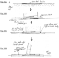
- the device is generally transformable from an OPEN position to a CLAMPED position. In the open position, the device is inserted through an incision in the dura, placing the intradural portion inside the dura. By clamping the dura between the intradural assembly and the extradural assembly, the device is secured to the dura in a leak-free manner, with the electrodes in direct contact with the cerebrospinal fluid.
- the transdural portion may include an outside surface and a vertical or longitudinal axis, which is positioned perpendicularly to the surface of the dura after implantation.
- the intradural assembly typically aligns with and conforms to an internal surface of the dura. It is either affixed or is slidably or rotatably connected to the transdural portion. It has a clamping portion that extends or is extendible to a position that is radially beyond the outside surface of the transdural portion.
- the clamping portion upon implantation, extends in one or more directions that are perpendicular to the longitudinal axis, either linearly along the anterior posterior axis or curving along the rostral caudal axis so as to conform to the inner surface of the dura, or both, so that the clamping surfaces of the intradural portion are in contact with the inner surface of the dura.
- the extradural assembly conforms to an external surface of the dura, wherein the extradural assembly is either affixed or is slidably or rotatably connected to the transdural portion.
- the clamping portion of the extradural assembly extends or is extendible to a position that is radially beyond the outside surface of the transdural portion. This means that upon implantation, the clamping portion extends in one or more directions that are perpendicular to the longitudinal axis, either linearly along the anterior posterior axis or curving along the rostral caudal axis so as to conform to the outer surface of the dura, or both, so that the clamping surface(s) of the extradural portion are in contact with the outer surface of the dura.
- one or both can include an aperture that is complementary to and encompasses the outside surface of the transdural portion. This configures the respective assembly to slide over or around the outside surface of the transdural portion such that the spacing between the intradural and extradural assemblies can be narrowed from an open position to a clamped position.
- the intradural assembly is configured to pass through a short incision in the dura surrounding the spinal cord when the device is in the open position, leaving the extradural assembly outside the dura, whereafter sliding or rotating the extradural assembly and/or the intradural assembly over or around the outside surface of the transdural portion to narrow the distance in between and securing the intradural and extradural assemblies in the clamped position has the beneficial effect of clamping the dura between the clamping portions of the intradural and extradural assemblies.
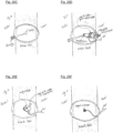
- the device shown in FIGS. 1 and 2 has an intradural assembly 6 that is affixed to the transdural portion 11 and 12.
- the extradural assembly 7, 8, and 10 is configured to slide over the outside surface of the transdural portion 11 and 12 towards the intradural assembly 6.
- the outside surface of the transdural portion around the longitudinal axis can be cylindrical, or any other shape that allows the extradural assembly to be brought towards the intradural assembly and secured in the clamping position to the transdural portion.
- a part of the transdural portion 12 has threading to receive and retain the lock nut 14.
- the base plate of the intradural assembly 6 and the base plate of the extradural assembly 10 are oval, ellipsoidal, rectangular, or oblong in shape so that the surgical incision made during implantation of the device is occluded between the intradural and extradural assemblies when the device is in the clamped position.
- a plurality of electrodes may be arranged along the long axis of the oblong shape of the intradural assembly.
- the intradural assembly is a spiral or an open circle in shape so as to be rotatably insertable through a narrow incision.
- the extradural assembly is round and has a perimeter that aligns with the perimeter of the intradural assembly, so that they may clamp the dura between them.
- the number of electrodes present may be at least one, two, four, seven, or ten or more, arranged in a one, two or three dimensional array along the intradural assembly, the transdural portion, the flange arms, or combinations thereof.
- any suitable securing means may be used that holds the intradural clamping surface and the extradural clamping surface in sufficient proximity to secure the device to the dura.
- FIG. 2 An exemplary means for clamping the extradural assembly to the intradural assembly is shown in FIG. 2 .
- the transdural portion 11 and 12 is attached to the intradural portion 6.
- the extradural portion 10 has an opening that circumscribes and slides over the transdural portion, clamping the dura 18 against the intradural portion 6.
- the lock nut 14 screws down the outer thread on the transdural portion 12, tightening the extradural portion to the intradural portion in the clamped portion, and reversibly securing it in place.
- Other options for clamping the extradural assembly to the intradural assembly include one or more prongs or securing snaps extending radially outward from the circumferential perimeter of the transdural portion, optionally spring loaded. Prongs or snaps of this kind are shown as component 34 in FIG. 14 .
- the extradural gasket slides downwards along or over the transdural portion to a position beyond the prongs or snaps, which thereafter prevent the gasket from sliding back up the transdural portion.
- a snap in the manner of a snap button with a male component on the extradural gasket and a corresponding female component on the transdural portion (or vice versa).
- a tongue and groove system such as a bayonet-style connector, with a tongue located on the extradural assembly and a corresponding groove located on the transdural portion, or vice versa, that engage when the extradural assembly is sufficiently close to the intradural assembly to apply a securing force between the clamping surfaces to the dura.
- a tongue on the extradural assembly may slide down a groove in the transdural portion whereupon the extradural assembly can be rotated about the transdural portion to a position that locks the extradural assembly in place in the clamped position.
- the securing means on the transdural portion may include one or more elements selected from prongs, the male or female portion of a snap, the male or female portion of a tongue and groove system, ratchet-like couplers, or a thread system that interacts with corresponding members on the extradural device. Suitable lubricants may be used to facilitate the implantation of the device components, and suitable adhesives may be used to facilitate the securing of the device components and the dural seal.
- the device When the device is implemented such that the intradural assembly is slidably or rotatably connected to the transdural portion, it may be moved towards the extradural assembly and secured in position using the same features as with the extradural assembly, mutatis mutandis.
- the intradural assembly of the device is also transformable: specifically, from an INSERT or RETRACTED position to a DEPLOYED position in which a clamping portion of the intradural assembly extends radially beyond the outside surface of the transdural portion.
- the intradural assembly can be constructed to include multiple flanges, wherein at least one of the flanges is moveable from a retracted or insert position.
- the flanges are underneath or inside the transdural portion or are parallel with each other so they can be stacked on top of each other.
- part of each of the flanges is extended radially beyond the outside surface of the transdural portion in a different direction.
- FIGS. 11B and 11C show an example in which the intradural assembly comprises both a circular component affixed or connected to the transdural portion with a clamping portion that extends radially to a position beyond the outside surface of the transdural portion, and at least three compliant flanges, wherein at least two of the flanges are rotatably movable from an insert position in which the flanges are parallel with each other to a deployed position in which each of the flanges extend away from the transdural portion in a different direction.
- One or more of the flanges may include a flange arm that extends radially beyond the transdural portion by at least 1 cm.
- One or more of the flange arms may include two or more separate electrodes arrayed along the length of the arm.
- each of the rotatably deployable flanges may be connected to an axle that passes through the transdural portion in the direction of the longitudinal axis to an opposing or outward facing surface of the transdural portion such that rotating the axle from the opposing surface moves the flange from the insert position to the deployed position.
- the device can have at least one electrode positioned on or near the longitudinal axis so that when the device is secured to the dura, the electrode is inside the dura, oriented towards the spinal cord. Alternatively or in addition, there may be one or more electrodes arrayed on the intradural assembly.
- the device may also have a socket or coupling (for example, with screw threads or a tongue-and-groove locking system) for reversibly securing the device to a positioning tool such that the device can be manipulated to place the intradural assembly inside the dura, whereupon the positioning tool can be removed from the socket.
- This invention includes such devices in combination with a signal source that delivers electrical stimulation to the spinal cord of a subject by way of the device.
- the signal source may be included in the device itself, but is often implanted elsewhere in the subject. Power can be transmitted from the signal source to the device wirelessly or by way of wire leads connecting the two.
- the electrical stimulation provided with the signal source may vary or fluctuate at a frequency that is sufficiently high to induce stochastic depolarization and/or to reduce pain transmission through the spinal cord. This may be a frequency of at least about 200 or 500 Hz, or as explained in more detail below.
- a subject can be prepared for treatment of pain, movement disorder, spasticity, or other indications by gaining surgical access to the dura surrounding the spinal cord of the subject, making a short incision in the dura, positioning a device of this invention such that the intradural assembly is inside the dura, the transdural portion passes from inside the dura to outside the dura, and the extradural assembly is outside the dura, narrowing the distance between the intradural assembly and the extradural assembly to a clamped position, and securing the intradural and/or the extradural assembly in place so as to sustain the clamped position, thereby securing the device stably to the dura.
- installation of the device includes rotating at least one of the flanges to a deployed position whereby each flange is oriented in a different direction before narrowing the distance between the intradural and extradural assemblies to the clamped position.
- the clamping portions of the intradural and extradural assemblies may seal the dura to prevent leakage of cerebrospinal fluid into the epidural compartment or egress of epidural effluents into the intradural compartment. Any open gaps or leakage can be repaired by the operating surgeon using suture, staples, glue, or any other appropriate closure materials. The surgeon then connects the device to an appropriately programmed and equipped signal source.
- the invention also provides various configurations of a positioning or inserting tool for clamping a device of this invention to the dura surrounding the spinal cord of a subject.
- a positioning or inserting tool for clamping a device of this invention to the dura surrounding the spinal cord of a subject. The nature and operation of the tool are described in more detail in the sections that follow.
- Positioning tool Proximal end of central axial shaft 1
- Proximal fixation fitting Proximal rotation hub 3
- MIS insertion shaft assembly 4
- Distal hub 5
- Rotational coupler for extradural lock nut 9
- Electrode assembly Intradural electrode substrate and compression plate 6
- Extradural compression plate 10
- Transdural housing for electrode array connector 11
- Extradural threaded stud Distal end of central axial shaft 13
- Lock nut in fully engaged position 14
- Gasket 15 Electrical leads 19
- Intradural electrode array 20
- Other components Epidural stimulator implant 23
- Electrical leads of epidural stimulator implant 24
- Implantable pulse generator (IPG) 25
- First independent channel of IPG 26
- Second independent channel of IPG 27
- Anatomical and surgical features Stabilization suture 16 Eyelet 17
- Dura mater 18
- FIG. 1 shows details of the compression plate 6 of the intradural assembly, which serves as a substrate for an electrode array configured for positioning in the intradural space.
- the transdural portion 11 and 12 is affixed directly to the intradural assembly 6.
- the upper portion 12 (an axial extension of the distal base bushing 11) has an outer thread that engages the locknut 14.
- the intradural compression plate 6 is T-shaped in profile, with the crossbar of the T located on its contra-lateral side (shown on the right).
- Distal bushing 11 has lateral and contralateral extension tabs, each of which serves as a positional index that secures the alignment of the compression plate 10 of the extradural assembly.
- the distal bushing 11, the threaded-stud fitting 12, and the central axial shaft distal end 13 are hollow inside. This serves as the containment for electrical leads connected to the electrode array on the distal surface of the extradural compression plate 6. The leads extend from that connector through the length of the assembly, and ultimately exit the aperture at the proximal end of the central axial shaft.
- the device components are typically made from biocompatible polymers such as polyether ether ketone (PEEK), except the electrode array, its connectors and leads, and the compression gaskets.
- Gaskets 15 can be attached to the compression plates using adhesives, mechanical clamping mechanisms, or combinations thereof.
- the gaskets 15 are shown as the layers of the assembly sandwiched between the dura 18 and the compression plates 10 and 6. I n this particular illustration, the gaskets are substantially the same size and shape at the compression plates 6 and 10.
- the gasket extend beyond the edges of one or more of the compression plates or gaskets that have a surface area that is smaller than the surface area of the compression plates.
- either single-layer or multi-layer gaskets are not adhered to the compression plates, but form a seal preventing leakage of the CSF upon implantation and tightening of the device around the dural membrane.
- the gaskets can be made out of a biocompatible material that is capable of creating a seal and preventing CSF leakage.
- Suitable materials may include polyurethane, polyamide-polyurethane, collagen dura membranes, polylactide-co-glycolide, polyethylene glycol hydrogel, silicone rubbers, silicone caulks, silicone resins, polysiloxanes, and low-durometer elastomers, combinations thereof, and compositions that include as a component one or more of these materials.
- FIG. 2 shows the locking nut 14 after it has been rotationally driven into place on the threaded adjustment fitting 12, which results in optimal positioning of the extradural compression plate 10 directly above the intradural compression plate 6.
- the intradural compression plate 6 is T-shaped in profile, with the crossbar of the T located on its contra-lateral side (shown on the right).
- the extradural assembly includes contralateral interlock notch mechanisms 7 and 8 that reversibly engage corresponding notch mechanisms on the positioning tool.
- the dura mater extant between the compression plates is compressed on both the proximal and distal surfaces by gaskets positioned between the distal side of the extradural compression plate 10 and the proximal side of the intradural compression plate 6.
- the gaskets ensure a watertight seal against leakage of CSF either through the durotomy opening or via any other pathway between the intrathecal space and the epidural space.
- the gasket material can be bioresorbable so as to fuse over time with the dura mater to form a fully re-approximated anatomical membrane with biomechanical characteristics that are substantially identical to the native dura mater membrane.
- the other device components are typically made of biocompatible polymers such as PEEK, except the electrode array and its connectors and leads, and the compression gaskets.
- the sealing effects achieved by the compression gaskets may be augmented with layers of tissue sealant films applied to the gaskets before implantation, and/or with auxiliary sutures, glues, adhesives, blood patches or other materials.
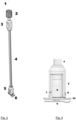
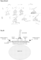
- FIG. 3 shows a full side profile view of the pre-deployed configuration, with the combined intradural assembly 6 and extradural assembly attached to a positioning tool 1 to 5.
- the positioning tool is a surgical implement used to place and secure the combined assembly in position on the dural membrane of the spinal cord at a chosen location. During the implantation procedure, the positioning tool is used to reconfigure, the assembly from the open position to the clamped position, where it is secured in the dural membrane by way of the locking nut. The positioning tool is then removed from the surgical field for reuse or disposal, allowing the surgeon to close the wound with the electrode assembly in place.
- the positioning tool has a proximal end (top) and a distal end (bottom). It extends longitudinally downward through the device and terminates inside a fixture within the distal hub assembly 5. Electrical leads from the intradural electrode array 6 at the distal end of the positioning tool traverse the length of the central axial shaft and exit from its proximal end aperture.
- the upper rotation hub 3 is used to twist the cylindrical housing shaft 4 about the longitudinal axis of the tool in order to tighten a lock nut onto the threaded shaft of a connector housing, both of which are inside of distal hub assembly 5. This draws together the intradural compression plate 6 and the extradural compression plate 10 so that gaskets between them are forced against the spinal dura mater and sandwich it between them to form a watertight seal against leakage of cerebrospinal fluid.
- the knurled upper fixation fitting 2 is used to maintain components 3, 4, and 5 in axial order as shown and to ensure continuous rotation of 4 in response to a manually applied twist of 3.
- components 3, 4, and 5 can be withdrawn from the assembly, leaving just the distal intradural and extradural assemblies in place, along with the transdural portion.
- All of the device components are typically made of biocompatible polymers, such as polyetheretherketone (PEEK) except the electrode array and its connectors and leads, and the compression gaskets.
- PEEK polyetheretherketone
- FIG. 4 shows the extradural and intradural assemblies at the distal tip of the positioning device.
- the cylindrical housing shaft 4 passes into the proximal end of the distal hub assembly 5, which surrounds the rotational coupler 9 for the extradural lock nut 14.
- the distal hub assembly 5 is mated to the extradural compression plate 10 by the lateral and contra-lateral interlock notches 7 and 8, respectively.
- Rotation of the coupler 9 draws upwards a threaded-stud housing attached proximally to the intradural compression plate 6 so as to compress gaskets integral to the distal side of 10 and to the proximal side of 9 onto a dura mater which is traversed by the threaded-stud housing, thus forming a leak-free seal against egress of CSF from within the thecal sac into the epidural space.
- the intradural compression plate 6 has a T-shaped in profile, with the crossbar of the T located on its contra-lateral side (shown on the right).
- the device components are typically made of biocompatible polymers such as PEEK, except the electrode array and its connectors and leads, and the compression gaskets.
- the gaskets can be made from known materials that are used in dural replacement procedures.
- the gaskets may have thicknesses in the range of 0.1 mm to 0.7 mm as appropriate to the scale of the implant and the thickness of the patient's dura mater.
- the gaskets may be coated with dural sealant films or membranes to help achieve a leak-free closure of the dura.
- the seal is typically augmented naturally over time by scar tissue that forms in response to the presence of the intradural components.
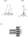
- FIGS. 5A (side view) and 5B (rostral-caudal view) show close-ups of a mechanical stabilization means for securing the extradural elements of the implant within the patient.
- the device shown here includes a take-up suture 16, which is threaded through lateral and contralateral eyelets 17, which extend proximally from the extradural compression plate 10. After the lock nut 14 has been used to tighten the extradural compression plate 10 against the intradural compression plate 6, fixing the dura mater 18 between them, the take-up suture 16 is threaded in place as shown.
- the proximal ends are secured directly to extradural fascial tissues, thus ensuring that the implant is suspended stably above the spinal cord, providing stress relief for the electrical leads 19 that connect the intradural electrode array underneath the distal compression plate to a pulse generator implanted elsewhere within the patient's body.
- FIG. 6 shows a possible geometry for an intradural electrode array 20, mounted on the distal side of the intradural compression plate 6.
- the array 20 is manufactured in the shape of the letter "T".
- the electrodes along the long (rostral-caudal) axis of the intradural compression plate 6 help stimulate nerve fibers in the dorsal columns of the spinal cord.
- the electrodes along the short (lateral) axis of the intradural compression plate 6 help steer the stimulation field to achieve selective activation of target structures elsewhere within the spinal cord, without inadvertently activating the dorsal nerve rootlets or other off-axis structures that could produce discomfort, pain or paresthesias in the patient.
- Individual electrodes may be treated by laser etching or some other suitable method for the purpose of generating nano- and micro-patterned structures to increase their active surface area by, for instance, 2-fold, 5-fold, or more in order to generate current densities at the electrode-CSF interface that maximize the therapeutic response of the treatment while minimizing the risks of neurotoxicity due to electrolytic effects and excessive charge densities.
- the electrical leads from the electrode array may be attached to an intermediate body inside the extradural components of the device. This may provide an interface structure for stress relief for the very fine wires or conductors that exit from the thin film electrode array.
- the leads from the electrode array are connected directly to a lead bundle that extends proximally from that connection point to the outside of the extradural components of the implant, at which point the lead bundle is secured to the body tissues.
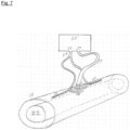
- FIG. 7 shows the intradural assembly combined with the extradural assembly, achieving extended coverage of the spinal cord, with improved targeting of critical structures and avoiding non-targeted structures.
- the intradural array 20 is inside of the dura mater 18 and suspended over the spinal cord 20.
- the electrical leads 19 from the intradural array 20 are interfaced with one independent channel 27 of an implantable pulse generator 25.
- Also shown are standard cylindrically-shaped, low profile epidural stimulator implant leads 23, which are positioned in the extradural space rostral and caudal to the intradural implant.
- the electrical connector 24 from the epidural stimulator implant leads 23 is interfaced with another independent channel 26 of implantable pulse generator 25.
- This arrangement allows the clinician to use combinations of extradural and intradural stimulation to achieve the best clinical results for the patient, and also allows combined epidural and intradural sensing of evoked compound action potential for use in closed-loop stimulation algorithms.
- the intradural stimulator array may be inserted first, and then the epidural leads are slipped into the extradural space rostral and caudal to the intradural array.
- the electrical leads of both the intradural and extradural implants is then connected to the implantable pulse generator 25.
- This arrangement allows for exhaustive and rigorous testing of key neurophysiological hypotheses. For example, the user could directly compare extradural vs. intradural stimulation in the same subject and test combinations of intradural and extradural contacts in various montages, with the goal of identifying, implanting and implementing the optimal configuration of devices for the needs of the patient.
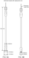
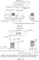
- FIGS. 8A, 8B , 9, and 10 show possible geometries and measurements for the electrode assembly and positioning tool shown in FIGS. 1 to 4 .
- the intradural plate 10 and the extradural plate 6 are about 1.5 cm by 0.5 cm in shape. They are attached by way of a 1.0 cm socket to the positioning tool, which is 18.5 cm in length.
- the intradural compression plate 6 is thin (0.5 to 1.5 mm) so as to minimize the risk of impeding the flow of CSF through the gap between the plate and the underlying spinal cord.
- the plate is shown here as oval, which when positioned parallel to the spinal cord helps seal the incision in the dura.
- the peripheral edges of the plate are typically smooth and free of burrs or other production artifacts that could pose a risk of tearing or scarring the dura mater.
- the planar surfaces are smooth to ensure optimal contact with the gasket used to seal the dura mater against the plate.
- Intradural assembly 11 Intradural gasket 12 Intradural clamping surface 13 Electrode 14 Flange 15 Flange rotator 16 Extradural assembly: 21 Extradural gasket 22 Extradural clamping surface 23 Transdural portion: 31 Lead 32 Socket 33 Securing member 34 Flange rotator 35 Connecting surface of rotator 36 Positioning tool: Inner housing 41 Compression sleeve 42 Handle 43 Positioning rod 44 Groove 45 Flange control rod 46
- FIGS. 11A, 11B, and 11C show an implementation of the device using compliant flange arms as part of the intradural assembly.
- FIG. 11A is a side view, showing the transdural portion 31 with wire leads or lead bundle 32 for connecting to a signal source (not shown).
- the intradural assembly 11 includes one or more electrodes 14 and turnable flanges 15 that have an intradural clamping surface 13.
- the extradural assembly 21 includes an extradural gasket 22 with an extradural clamping surface 23.
- the extradural assembly is configured to slide downwards along the outside surface of the transdural portion 31 until it is held in position by securing members 34.
- a socket or receiving member 33 for reversibly securing the device to a positioning tool. This allows the device to be manipulated to place the intradural assembly inside the dura, whereupon the positioning tool can be removed from the socket.
- a flange rotator 35 passes through the transdural portion from each of at least some of the flanges so that the flanges can be rotated into the deployed position from outside the dura.
- the diameter of the extradural assembly may be in the range from 5 to 9 mm.
- the length of the flange arms is in the range from 0.5 to 2 cm, with a thickness of 1 to 2 mm.
- the flanges and the flange arms can be made of a soft polymer like silicone, possibly with a stiffening element: for example a wire or stiff polymer material, inserted inside of the flange arms to give them axial stiffness while still maintaining torsional compliance that accommodates the curved surface of the dura during flange rotation, without risk of rupture, tear or abrasion.
- the extradural gasket can also be made of a soft polymer such as silicone, providing it is sufficiently rigid to keep the dura sealed around the original incision.
- the actual electrodes themselves may be of any suitable shape and construction, such as a small flat disk, a "spherical cap” (partial hemisphere), or a half-moon shape. They can be made of platinum or of a platinum-iridium alloy. Each electrode typically has an electrical lead welded or otherwise in permanent, secure, low-resistance ohmic contact with its proximal side.
- FIGS. 11B shows the flanges 15 in a substantially parallel orientation from beneath the transdural portion 31. This is the retracted or insert position, whereby the surgeon may insert the flanges together through an incision in the dura.
- FIG. 11C shows the flanges 15 rotated to the deployed position, anchoring the intradural assembly underneath the dural membrane.
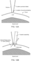
- FIGS. 12A to 12E show how this device can be secured to the dura of a subject.
- the dorsal surface of the spinal dura is accessed using the standard surgical approach. The exposure achieved with minimally invasive surgery (MIS) devices and methods are adequate for this purpose.
- MIS minimally invasive surgery
- a suture, or micro-hook instrument is used to "tent up” the dura (raising it further above the surface of the spinal cord) in preparation for making a small puncture incision through the dura.
- a custom blade can be used to create a durotomy of the precise length required.
- FIG. 12B shows an inserting tool 40 (described further below) being used to secure the device.
- the device has the extradural gasket in the open position, an electrode 14 inside the dura oriented towards the spinal cord, and the flanges 15 in the insert position.
- the inserting tool can be configured so that one of the flanges 15 is rigidly fixed to the transdural portion with no positional controller attached to it.
- the rotational position of the other two internal flanges 15 are each controlled through its own flange rotator 16, which in turn is manipulated using a flange control rod that passes through the body of the inserting tool, as described below.
- the flanges 15 are oriented substantially parallel with each other, the tips of each flange facing substantially in the same direction.
- the device with the flanges in the insert position serves as the blade of a dural separator, allowing it to be introduced into the subdural space with the flanges flush with the dura, exerting an upward pressure on the dura to elevate the membrane away from the spinal cord.
- FIG. 12C shows the flanges 15 rotated to the deployed position, anchoring the device underneath the dura.
- Two of the flanges 15 can each be rotated independently by the surgeon using the flange rotators in the transdural portion. The surgeon controls the rotational position or angle of two of the flanges through flange control rods that extend from the opposite end of the inserting tool 30 (the portion closest to the surgeon's hand).
- the dural edges are now located within the space between the flanges 15 and an extradural gasket 22, shown here in the up or open position.
- the clamping surface of the gasket can be fabricated from an artificial dura material.
- the outer surface of the gasket and most of the rest of the device can be fabricated of a rigid, biocompatible polymeric compound that may be MRI compatible.
- FIG. 12D shows the extradural gasket 22 compressed downwards against the flanges 15 by the inserting tool 40.
- the surgeon slides the extradural gasket compression cylinder down the assembly 40 towards the dura, thereby pushing the extradural gasket 22 past securing snaps 34 to achieve a snug, watertight closure onto the dura.
- Fabricating the undersurface of the gasket using an artificial dura-type substrate facilitates rapid tissue fusion of the gasket to the dura: for instance, by resorption of the dural substitute at the interface with the dura.
- the securing snaps 34 lock the gasket into the secured position.
- FIG. 12E shows the electrode device secured to the membrane with the inserting tool removed.
- the extradural gasket assembly 22 clamps the dura against the flanges 15, thereby positioning an electrode 14 so that it projects downwards from the dura towards the spinal cord.
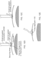
- FIGS. 13A, 13B and 13C depict another inserter assembly or inserting tool that is suitable for use in implanting an electrode device of this invention into a subject.
- the inserting tool is adapted for operation of a device as shown in FIGS. 11A, 11B, and 11C with moveable flange arms.
- the electrode device itself is not shown.
- FIG. 13A depicts a side view.
- Three control elements extend from the top of the device and are controlled by the surgeon.
- two flange control rods 46 are used to control and adjust the position of two moveable flanges that are part of the electrode device.
- the positioning rod 44 reversibly connects the inserting tool to the electrode device.
- An extradural gasket compression cylinder 42 is shown in the UP position around the inner housing 41.
- Four cross-sectional images are shown depicting the internal structure of the device. In the lower two cross-sectional views a groove 45 is shown that accommodates placement of the electrical lead on the device.
- FIG. 13B is a frontal view of the inserting tool by itself. This provides a view of the groove 45 that accommodates the wire lead.
- FIG. 13C is a frontal view with the extradural gasket compression cylinder 42 in the DOWN position. To install devices that do not have rotatable flanges, the flange control rods are not needed.
- the external surface of the inserting tool may conform to an oval or elliptical shape, rather than a circle, and are typically complementary to the outer surface of the extradural assembly.
- FIG. 14 shows the electrode device coupled with the inserting tool.
- the electrode device aligns with the housing 41 of the inserting tool, meaning that the surface of the transdural portion 31 of the device has a cross-sectional shape or diameter that is substantially the same as the housing 41.
- the device is kept in place at the bottom of the housing by way of the positioning rod 44 inserted into the socket 33 of the transdural portion.
- the inserting tool has a groove 45 to accommodate the lead 32 that ultimately connects the electrode 14 to the outside signal source.
- Each flange control rod 46 connects with a reversible interface 36 at the top of flange rotator 35 housed in the transdural portion 31 of the device, which is used to rotate the respective flange 15 to adjust the angle or intradural orientation.
- the interface 36 is depicted here as a slot-headed dome. In the alternative, the interface can be cross-shaped or hexagonal, matching a corresponding pattern in the flange control rod 46 of the inserting tool.
- the inserting tool has a positioning rod 44 that passes from the top of the inerter that projects away from the device, down through the inserting tool to the opposite surface where the inserting tool abuts the electrode device.
- the positioning rod 44 reversibly interconnects with the socket 33, shown here with a screw interface, thereby securing the electrode device to the bottom of the inserting tool.
- FIGS. 15A, 15B, and 15C depict operation of the inserting tool in combination with the electrode device.
- the surgeon controls the rotational position of the flanges 15 using the flange control rods 46 of the inserting tool, thereby deploying the flanges 15 to different orientations as shown in FIG. 15B , and anchoring the intradural assembly underneath the dura.
- the surgeon slides the compression sleeve 42 down the housing 41 of the inserting tool, thereby sliding the gasket 22 down the transdural portion 31 of the electrode device to a position where it is secured by the snaps 34.
- the edges of the dural incision are firmly compressed between the gasket 22 and the flanges 15, preventing a CSF leak.
- the inserting tool is then disengaged, leaving the electrode device stably AMD safely secured to the dura.
- At least one anode and at least one cathode are positioned on or around the intradural assembly or the transdural portion, to complete the entire electrical circuit within the intradural space.
- Efficiency can also be gained over presently available SCS systems by using a combined electrode array or epidural and intradural electrodes, due to the beneficial location of the intradural electrodes.
- the electrode device can be designed with more distance between the electrodes.
- multiple electrode contacts can be positioned in a linear configuration parallel to the long axis of the spinal cord.
- multiple electrodes can be positioned along the inner surface of the dura, making it possible to deliver stimuli with electrode montages having spatial orientations that are perpendicular or at an angle of at least 45 or 60 degrees, compared with the long axis of the spinal cord.
- positive and negative electrode contacts positioned in the left and right lateral positions within the thecal sac, the targeted neural tissue (the dorsal rootlets, the dorsal root entry zone, and the dorsal columns) are optimally located in the space between the contacts on either side.
- the flange arms of the intradural assembly are constructed to be longer, therefore providing more distant spacing of the electrodes.
- Flange arms intended to wrap against the dura at least partly around the spinal cord are generally made of a semirigid compliant material that can conform to the inner surface of the dura without risk of rupture, tear or abrasion.
- the entire flange can be made of the same material, or the part of the flange near the flange rotator can be made of a more rigid material, joined to a more compliant material further along its length.
- Each flange arm can be arrayed with a plurality of electrodes, optionally in a pattern that is linear, nonlinear or fractal in configuration, and with surfaces that might be nano- or micro-patterned to increase their effective area relative to the nominal geometric area.
- the electrode arrays on each flange arm bend and conform to the inner arc of the dura as required.
- the compliance of the flange arms accommodates changes in the thecal sac (the dural lining) that accompany normal movements of the subject.
- FIG. 16A is a superior oblique view of an electrode device with an array of electrodes 14 along one of the flange arms 15.
- FIG. 16B is a bottom-up oblique view of the electrode device.
- FIG. 17A shows insertion of the electrode device through a small durotomy incision.
- the distal portion of the flange arm 15b with the outermost electrode is inserted into the opening first, followed by the proximal portion 15a near the transdural portion.
- the implanted electrodes 14a, 14b and 14c form a one-dimensional intradural array.
- FIG. 17B depicts another version where all three flanges are extended and bear electrode arrays.
- the three flanges are oriented parallel and lie on top of each other. They are introduced into the subdural space as a bundle.
- two of the flanges are rotated to the deployed position. The electrodes are thereby caused to slide back along the inner surface of the dura into the positions shown.
- FIG. 17C is a cross-sectional schematic depicting the location of contacts on the electrode arrays that have been rotated into lateral positions along the undersurface of the dura.
- the electrode devices of this invention can also be constructed without rotatable flanges on the intradural assembly.
- an intradural gasket of fixed shape that has an intradural clamping surface oriented upwards in the direction of the transdural portion.
- the options below can be combined with any features referred to elsewhere in the disclosure with respect to other components of the device.
- FIGS 18A to 20D illustrate an asymmetric linear array (ALA).
- the intradural and extradural assemblies are elongated in shape in the manner of an oblong or ellipse, being off-center with respect to the transdural portion of the device, having a long arm and a short arm. This configuration is beneficial because it spans the incision made in the dura during implantation, thereby providing a superior seal.
- FIGS 18A and 18B are drawings of the intradural assembly and transdural portion of an ALA device.
- the long arm of the intradural assembly can be of any suitable length and house any suitable number of electrodes in a linear, two-dimensional, or fractal array.
- the long arm 11a is inserted through the dural opening in the manner by which a right angle dural separator is used to access the subdural space.
- the short arm 11b of the intradural assembly extends a sufficient distance from the transdural portion 31 to provide an adequate clamping area to clamp the device towards the overlying external gasket.
- FIG. 18C depicts an inserting tool adapted for implanting an ALA device.
- the positioning rod 44 is used to reversibly attach the inserting tool to the device.
- the compression cylinder 42 is shown in the UP position in relation to the inner housing 41.
- the surgeon compresses the extradural gasket 22 onto the electrode device assembly by moving the compression cylinder 42 downward, advancing the extradural gasket 22 past the securing snaps 34.
- the electrode lead 32 is positioned within a space created by aligned grooves 45 in the housing 41 of the inserting tool and the compression cylinder 42. This inserting tool has no flange control rods.
- the surface of the housing 41 (as viewed in cross-section) is oval in shape rather than circular, and the compression cylinder 42 has substantially the same asymmetric cross-section as the ALA device itself.
- the external compression cylinder fits snuggly over the entire surface of the intradural ALA device - thereby securing the clamping surface 23 of the extradural assembly adj acent to the clamping surface 13 of the intradural assembly.
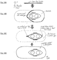
- FIGS. 19A to 19D provide a top-down, or surgeon-eye view of an exemplary ALA device insertion procedure.
- a single linear incision is created in the dura. The length of the incision is sufficient to accommodate placement of the intradural assembly, but no longer ( FIG. 19A ).
- the long arm 11a of the intradural assembly is inserted into the subdural space using the right angle dural separator dissecting technique ( FIG. 19B ).
- the intradural gasket is lifted, and dura is stretched in order to slip the short end 1 1b of the intradural gasket into the subdural space, similar to a button being inserted through an eyelet or the head of a rivet through its mating component ( FIG. 19C ).
- the surgeon positions the intradural assembly such that the cut edge of the dura tightly abuts the transdural portion 31 next to the short arm 11b. This results in the dural gap being positioned over the long arm 11a of the intradural assembly. There is a greater surface area available for compression of dural edges over the long arm 11a.
- the surgeon slides the extradural gasket 22 down the transdural portion 31 where it is secured in place by the snaps 34. She then disconnects the inserting tool from the electrode device, leaving the implanted electrode secured to the dura in a watertight or leak-free manner (FIG. 9D).
- FIGS 20A to 20D show steps of the ALA device implantation procedure from a sideview perspective.
- the linear dural incision ( FIG. 20A ) is substantially shorter than the length of the ALA device.
- the long arm 11a of the intradural assembly is inserted first ( FIG. 20B ) followed by the short arm 11b.
- the device is positioned in the incision such that the gap extending beyond the transdural portion 31 is located over the long arm 11a of the intradural assembly.
- the extradural gasket 22 is then lowered using the compression cylinder 42 until it is secured in position against the dura because of the snaps 34.
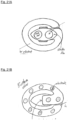
- FIGS. 21A to 24 illustrate a device designated W2, which includes another possible shape for the intradural assembly: specifically, a spiral, or an open circle or oval. This shape assists the surgeon to the intradural assembly through a very narrow incision in the dura.
- FIGS. 21A and 21B show top and bottom views of the W2 device without the extradural assembly.
- Multiple electrodes 14 are arrayed around the internal assembly 11, wired through the transdural portion 31 to the lead bundle 32.
- FIGS 22A and 22B show side and oblique views of the W2 device without the extradural assembly.
- a thin linear attachment 36 connects the intradural assembly 11 to the transdural portion 31.
- the attachment 36 fits snuggly within a small linear dural opening.
- the transdural portion can be reversibly connected to an inserting tool to assist the surgeon in implanting the device into the subject.
- the insertion tool has a shape that corresponds or conforms to the altered shape of the intradural assembly.
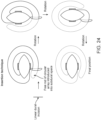
- FIGS. 23A and 23B show the configuration of a W2 device after insertion.
- the dura is compressed between the intradural assembly 11 and the extradural gasket 21.
- a near continuous circumferential intradural compressive surface area is created by the intradural assembly.
- the intradural assembly is typically rigid, so that edges of the intradural assembly on either side of the dural incision remain well aligned during insertion. This ensures that the dura spanning the gap is held in a sufficiently stable position to achieve a watertight or leak-free closure after the extradural gasket 22 has been moved down into the clamped position.
- FIG. 24 depicts a possible W2 insertion procedure.
- a small linear incision is made in the dura, just long enough to accommodate passage of the thin linear attachment feature 36 connecting the circular electrode array to the electrode housing.
- the leading or free end of the intradural assembly is advanced into the subdural space under direct visualization using the right angle dural separator dissection technique.
- the surgeon continuously advances and rotates the W2 until it is in the final fully inserted position and seated properly.
- the extradural gasket is then lowered onto the dura, achieving a watertight or leak-free seal, whereupon the device is disconnected from the inserting tool.
- FIGS. 27A-27F depict a device is designed to function as a port.
- the device includes one or more openings that are fluidically connected to the CSF and the extradural space, thus allowing for the transfer of liquid from the extradural space to the CSF.
- the opening(s) can be positioned in substantially the same variety of positions and configurations as those depicted elsewhere in this disclosure. For example, an array of openings can be included, or alternatively a single opening can be included.
- One or more valves can be included within the fluid conduit.
- the valve(s) can be positioned anywhere within the fluid conduit system, for example, at the location of the one or more openings or adjacent a reservoir. In some devices the valve(s) are unidirectional to prevent the movement of the CSF out of the intradural space.
- the devices can be used to deliver a variety of substances, for example, active pharmaceutical ingredients such as antibiotics, analgesics, cancer therapeutics, biologics and combinations thereof.
- active pharmaceutical ingredients such as antibiotics, analgesics, cancer therapeutics, biologics and combinations thereof.
- the delivery can be either passive or active.
- passive delivery can be accomplished using various selectively permeable membranes, or active delivery can be accomplished using pressure differentials, for example, extradural syringes, pressurized reservoirs or reservoirs associated with active pumps.
- a magnetic resonance (MR) scan is obtained of the thoracic spine of a patient identified as being a candidate for intradural spinal cord stimulation.
- the MR scan is reviewed by the clinician to determine the implantation site for the device.
- minimally invasive surgical techniques are used to create the durotomy, implant and then secure the device such that the electrode array is positioned in a leak free manner on the inside wall of the spinal dura mater.
- Electrode leads are connected to an implantable impulse pulse generator (IPG) and the surgical site is then closed in the standard fashion.
- IPG implantable impulse pulse generator
- the following description shows how an electrode device according to this invention may be implanted in a subject. This is provided by way of illustration for implanting a device according to FIGS. 11A to 11C . The procedure may be adapted mutatis mutandis for implanting other working models of the invention.
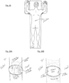
- the implantation procedure is typically performed under general anesthesia. As shown in FIG. 25 , the patient is positioned prone and an approximately 2-3 cm incision is made in the skin over the spinal vertebral level to be implanted. These illustrations depict the device being implanted at the T8-T9 level.
- FIGS. 26A and 26B shows how the surgeon gains access to the T8-T9 laminae using standard exposure techniques.
- the access achieved with standard minimally invasive surgery (MIS) is typically adequate.
- MIS minimally invasive surgery
- the surgeon uses standard MIS techniques to remove a portion of the caudal aspect of the T8 lamina, the rostral portion of the T9 lamina, and the ligamentum flavum that spans the gap between the two laminae. This results in the exposure of the underlying spinal dura.
- FIGS. 26C to 26F continue the procedure.
- the surgeon lifts up the dura using a sharp micro-dissector and creates a small durotomy opening using the custom sharp instrument that ensures that size of the dural opening is correct.
- the surgeon slips the flange control rods 46 of the insertion tool 41 into the dural opening.
- the flange control rods are in the insert orientation, meaning parallel and flush with each other, with the blades all facing in the same direction, corresponding to the insert or retracted configuration of the device itself.
- the surgeon manipulates the inserting tool using the same technique as is used with a right angle dural separator to achieve safe access to the intradural space.
- the surgeon orients the inserting tool perpendicular to the spinal canal and rotates the two flange position controllers to move the flange arms into the deployed position. This action causes the cut dural edge to be positioned tightly around the entire circumference of the device.
- the surgeon slides the handle 43 of the extradural gasket compression cylinder 42 down along the inserting tool until the gasket snaps into place, securing the device to the dura and substantially sealing the intradural space.
- the surgeon rotates the positioning rod 44 to unscrew and disengage the electrode device from the inserting tool.
- the inserting tool is then withdrawn and removed from the field, as shown in FIG. 26F .
- a robotic system could be used to perform some or all of these surgical steps,. controlled remotely by a medical professional.
- the device is connected to a power or signal source that is configured and programmed to deliver electrical stimulation to the spinal cord of the subject by way of the device.
- a power or signal source that is configured and programmed to deliver electrical stimulation to the spinal cord of the subject by way of the device.
- Any suitable signal source can be used that provides the desired intensity, frequency and duration of stimulation when electrically connected to the electrodes.
- the stimulation is typically controlled by suitably programmed digital circuitry, located typically in the signal source assembly.
- a “signal source” referred to in this disclosure is both a source of electrical power and a digital means for regulating the waveforms of the electrical power fed through to the electrodes of the device via the leads so as to deliver spinal cord stimulation (SCS) at a desired frequency or pattern.
- the digital control means can be (for example) a microprocessor, microcontroller, digital signal processor, or other electronic signal synthesis and control device that is suitable for this purpose.
- the device can be configured to receive energy from a power source wirelessly.
- the device may include a receiver disposed along the backing of an electrode assembly. Energy can be received, for example, from a signal generator and transmitter implanted at an extradural location.
- the signal source can be an implantable and externally programmable pulse generator, with integrated externally chargeable battery.
- the subject can be given a hand held control unit capable of programming the pulse generator and recharging the battery, all by wireless telemetry link.
- the signal source is generally located away from the spinal cord, such as in the misculature of the lower back.
- the transdural implant can in principle be connected to the signal source wirelessly or using an electrical lead bundle.
- the pulse generator can be configured and programed to deliver any one or more of the following: tonic mode stimulation (standard low frequency ⁇ 1 kHz), high frequency stimulation (> 1 kHz), burst mode stimulation (chirped pulse sequences or combinations of frequencies), pulse trains, noise signals, discontinuous waveforms such as square and triangle waves, and smooth waveforms such as sine waves, any one or more of these at amplitudes ranging from 10 mV or less to 10 V or more.
- tonic mode stimulation standard low frequency ⁇ 1 kHz
- high frequency stimulation > 1 kHz
- burst mode stimulation chirped pulse sequences or combinations of frequencies
- pulse trains noise signals
- discontinuous waveforms such as square and triangle waves
- smooth waveforms such as sine waves
- a signal source suitable for providing electrical signals to a subject by way of a device configured to be implanted in the dura according to this invention may be marketed with the device and implanted into a subject either separately or together.
- the device can be used for delivering an electrical stimulus to the target region of the spinal cord.
- the electrical stimulus typically comprises a pattern of electrical pulses that has been predetermined or is empirically determined to provide the patient with the desired benefit.
- the stimulus may be applied to inhibit sensation of pain, or to inhibit symptoms or sensory input that is undesirable or disruptive to the patient, including those due to spasticity resulting from spinal cord injury or morbidities, such as Parkinson's disease, multiple sclerosis, congestive heart failure, or visceral pain.
- the stimulus may be provided to the spinal cord by the device on a constitutive basis, in an automatic response to feedback data, by remote control by the managing clinician, or it may be subject to the patient's conscious control.
- the spinal cord is stimulated so as to inhibit pain transmission by applying directly to the spinal cord an electrical stimulus that renders sensory neurons refractory to transmission of synchronous action potentials initiated within the spinal cord.
- the electrical stimulus is thought to promote stochastic depolarization of sensory neurons within the spinal cord, thus inducing a state of neural quiescence.
- stimulation might be used to ameliorate visceral pain by targeted, reversible neuromodulation the post-synaptic dorsal column pathway within the spinal cord.
- Different stimulation algorithms can be used depending on the patient's needs. They might include tonic (standard low frequency) stimulation, high frequency stimulation, burst mode stimulation, stochastic waveform stimulation, and approaches that use special patterns or frequency combinations.
- Feedback can be used to monitor the excitation of the targeted neural structures, track the vital signs of the patient, and incorporate measurements or observations of the patient's posture and motor activity. Status of the equipment and its effect on the patient can optionally be monitored by the physician or other hospital personnel or caregivers via telemedicine techniques, direct connection of the stimulator to the internet or telephone network (either wired or wireless), or by any other means suitable for either one-way or two-way conveyance of stimulation parameters and settings and the patient's responses and condition.
- Sensing of neural activity resulting from stimulation can be employed to optimize the response to therapy, for example, via the measurement of evoked compound action potentials ( U.S. Patent No. 9,386,934 ; M. Russo et al., Neuromodulation, 21:38-47, 2018 ).
- the data obtained in that manner are recorded in the epidural space and hence are far-field in nature.
- sensing of the evoked compound action potentials becomes nearer-field in nature. This has a number of potential advantages, including less uncertainty in the isolation and identification of the target neural elements, less risk of movement of the sensing electrodes relative to the target neural elements, and improved signal-to-noise ratio.
- the therapeutic dose of current density into the targeted neural structures can be titrated, ramped or otherwise made adjustable for the purpose of optimizing therapeutic benefit to the patient.
- Current densities at any level within those approved by the U.S. Food and Drug Administration (FDA) for safe and efficacious delivery of SCS therapy can be used.
- the device is configured so that the treating clinician can at her option apply spinal cord stimulation using a voltage that alternates at high frequency. Regardless of the way the potential may vary over time, the frequency may be calculated by determining the number of positive-to-negative alterations per unit time. Effective frequency ranges depend on the anatomical placement of the electrode array, the features of the array, the nature, health, and electrophysiological characteristics of the tissue where the array is placed, and the objectives of treatment.
- the general object is to induce refractoriness of the spinal cord to transmit deleterious signals or synchronous depolarization events initiated locally. This can be adjusted empirically by determining neural activity and recording the symptoms experienced by the patient.
- effective pulse repetition rates or frequencies may be at or above 100 Hz (pulses per second), 200 Hz, 500 Hz, 2,000 Hz, or 5,000 Hz, a frequency of about 1,000 Hz, 4,000 Hz, or 10,000 Hz, or a frequency range of about 500 to 50,000 Hz, 1,000 to 9,000 Hz, 3,000 to 8,000 Hz, 2,000 to 20,000 Hz, or 5,000 to 15,000 Hz.
- the electrical stimulus may be adjusted in frequency or other waveform parameters, and manner of application so as to minimize side effects such as paresthesia, and to minimize impact on transmission of essential neurological faction, including motor neuron activity, and nerves involved in proprioception, kinesthesia, and either cognitively controlled or autonomous bodily functions.
- the clinician or the user may be provided with an input means to select the pattern, adjust the frequency, and adjust the intensity in accordance with the perceived symptoms and standards of practice.
- the electrical potential may vary at a regular frequency in a sinusoidal or square waveform.
- the waveform may be a more complex charge-balanced pattern, with pulses appearing at varying intervals and intensities according to a calculated, repetitive, or random pattern.
- Such patterns comprise a pulse train generating substantially continuous activation of nerves within the spinal cord, and may incorporate irregular pulse intervals, irregular pulse amplitudes, a variety of wave forms (for example, monophasic, biphasic, rectangular, sinusoidal, as well as asymmetric or irregular wave forms), or any combination thereof.
- the potential may also create what is essentially a broadband noise, varying at stochastic or essentially random intervals and intensity under the influence of a suitable computational algorithm or automated control program in the digital circuitry of the signal source.
- the electrodes through which the high-frequency stimulus is conveyed are typically arrayed on a pliable background, constructed of a material and in a shape that allows it to be conformed directly to the morphology of the spinal cord.
- the technology may be configured to apply different stimuli through different electrodes of the device, and to actively control the polarities of the individual electrodes within the array
- Treating pain according to this disclosure can include administering an electrical stimulus to the spinal cord, monitoring transmission of synchronous action potential through the spinal cord and/or pain experienced by the subject, and then adjusting the electrical stimulus so as to further inhibit or otherwise regulate transmission through the spinal cord of synchronous action potentials.
- the object may be anything that is clinically worthwhile, such as reducing sensation of pain (especially back pain) by the subject, such as may occur in the course of spinal cord injury, disease or strain of the spinal cord, Parkinson's disease, osteoarthritis, or congestive heart failure.
- spasticity features prominently include cerebral palsy, multiple sclerosis (MS), ischemic or hemorrhagic stroke, trauma to the brain, and spinal cord injury (SCI).
- MS multiple sclerosis
- SCI spinal cord injury
- Patients with long-standing spasticity are limited by pain and contractures that interfere with activities of daily living and hamper rehabilitative efforts.
- pharmacological and surgical treatments are available to reduce symptom burden, these therapies are neither curative nor restorative, and offer only partial or no selectivity.
- This invention includes direct SCS as an alternative approach to standard epidural spinal cord neuromodulation. It is superior to technologies currently being used commercially, because it directly activates the neural circuits that regulate spinal motor neurons. Much greater targeting selectivity of neural structures can be achieved by placing the electrode array intradurally. This is possible even at much lower stimulation amplitudes.
- An SCS device of this invention can co-opt and electrically integrate with targeted zones of the spinal cord to modulate a limited number of selected motor neurons - say those around the L3 segment. Stimulation interference paradigms may also play a role. Once the therapeutic effects are established in each patient, the treating clinician may toggle the stimulation controls selectively to first treat spasticity, and then to scale up with more sophisticated programming.
- Treating spasticity can include administering an electrical stimulus to the spinal cord, monitoring transmission of synchronous action potential through the spinal cord and/or symptoms of spasticity being experienced by the subject, and then adjusting the electrical stimulus so as to further inhibit or otherwise regulate transmission through the spinal cord of synchronous action potentials and/or signals of excessive velocity-dependent muscle contraction that result in the symptoms of spasticity.
- the therapeutic response will be optimized by virtue of the intradural location of the stimulator's electrode array, and also by the possibility of employing a combined epidural/intradural sensing method for measuring the evoked compound action potentials associated with the response to stimulation.
- the technology of this disclosure can be used to cause a disruption in the synchronous firing of axons, or a portion of axons within a nerve bundle.
- the disruption can be controlled by increasing or decreasing the frequency and/or power of the stimulation.
- a high frequency stimulation can be used to induce pseudospontaneous firing (random axon firing commonly associated with a state of non-sensory stimulation) thus causing the patient to not perceive pain.
- the frequency can be set such that stimulation is provided at a frequency that does not allow sufficient time for some, or all, of the axons in a nerve bundle to reestablish their membrane potentials.
- the frequency and power used to provide a therapeutic benefit will vary from patient to patient and that adjustments to the devices disclosed herein can be made using feedback from the patient or sensors included to identify and subsequently generate and control the optimum stimulation.
- a patient can be initially started on one therapeutic stimulation dose or regimen, and over time as the patient adapts to the dosage, a new dose or regimen is prescribed and applied.
- High frequency stimulation of the spinal cord may benefit the patent by inducing a state of pseudospontaneous axon firing.
- Bundles of sensory axons are thought to fire randomly when not transmitting sensory stimulus.
- a sensory stimulus is presented, a substantial proportion of the axons within a bundle or pathway discharges in a synchronous fashion - firing axons potentials at about the same time. This results in the sensory input being transmitted along the axons in the bundle, so that the subject may experience the sensation.
- the absence of sensation is coded by random timing of axon firing within a bundle, whereas a sensory perception is coded by synchronous firing of a population of axons.
- a high frequency electrical stimulus (say, about 5,000 Hz) has interval spacing shorter than the refractory period of axons.
- An individual axon cannot fire again in response to a second shock until its membrane potential has recovered from the effects of the first shock, and this takes time.
- Different axons have different refractory periods.
- Applying high frequency pulses to the spinal cord can be used to restore a state of active quiescence in the sensory nerves passing through the cord. This can inhibit transmission of undesired signals through the spinal cord, such as a sensation of pain in the spinal cord or extremities, or excessive muscle contraction signals that result in spasticity.
- Electrode device of this invention may be variously and interchangeably referred to as an electrode assembly or a button electrode assembly, and may be referred to by the mark I-Patch TM or I-Patch 2.0 TM .
- I-Patch TM I-Patch 2.0 TM .
- These terms refer to the medical device that is configured for implantation in the dura of a subject, either in the open position or the clamped position, with or without an inserting tool. Flanges or other deployable features if they are present may be in the insert position or in the deployed position.
- the signal source and the inserting tool are referred to and characterized separately, when used either separately or in combination.
- the "intradural assembly”, the "extradural assembly”, and the “transdural portion” of the device when present, refer to components of the device that have the structure and perform the action with which they are defined. They do not need to be in any particular physical space, either before or after implantation. After implantation, the intradural assembly is not required to be positioned entirely under the dura, the transdural portion is not required to go entirely across the dura, and the extradural assembly is not required to be positioned entirely outside the dura, unless explicitly stated or otherwise required. Similarly, a “gasket” is required only to do the function indicated, and may be made of any suitable material.
- positioning tool or device and “inserting tool” or device are used interchangeably to refer to an apparatus or part of an apparatus that is used by the surgeon while the combined electrode assembly is being implanted into the patient, and is then withdrawn from the surgical field for reuse or disposal, leaving the electrode assembly in place.
- the positioning tool is not necessarily included with an electrode assembly of the invention.
- the positioning tool may be supplied in combination with the electrode assembly, or it may be supplied separately and combined with the electrode assembly together in the operating theater.
- An electrode assembly of the invention may be implanted using a positioning tool of the invention, or with any other equipment that the surgeon deems suitable.
- Quantescence as the term is used in this disclosure in reference to a bundle of axons refers to a condition of stochastic depolarization or firing of axons within the bundle. It is a natural condition in which the neurological system may be actively signaling that there is no sensory input to be transmitted by the bundle as a whole. It may be induced by pseudospontaneous neural stimulation by applying effective high-frequency electrical pulse patterns in an appropriate manner as described here.
- Example 1 Testing of various gaskets for use with intradural stimulator
- the compression plates and housing of the prototype intradural stimulator of the type shown in FIGS. 1 through 4 were implanted into a mock durotomy slot that had been cut into a Plexiglas ® tube which simulated the thecal sac.
- a thin, smooth strip of polyethylene was used as the surrogate dura mater to insure that any leakage pathways would be associated only with the gaskets and not with porosity of the dural surrogate.
- the gaskets between the compression plates were made of Durepair ® , which is a dura substitute often used to close and seal durotomies.
- the gasket thickness was nominally 0.5 mm, and of oval shape with length and width matching the dimensions of those of the intradural plate as shown in FIG. 10 .
- a syringe was connected to one end of the Plexiglas ® tube and the other end was blocked shut.
- the tube was filled with water, with the hydrostatic pressure controlled manually by the force acting on the plunger of the syringe.
- a pressure meter was used to monitor the hydrostatic pressure within the tube, which could be increased to super-physiological levels.
- a durotomy slit was cut in the polyethylene strip and the stimulator assembly was implanted, with the Durepair ® gaskets on either side of the strip. The compression nut was then gently tightened to draw the intradural plate and extradural plate towards each other and produce closure of the durotomy, and the syringe was thereafter used to raise the hydrostatic pressure.
- the seal produced by the gaskets remained leak free at the maximum applied pressure of approximately 250 mm Hg, which was several times the peak intrathecal pressure observed in patients during a change of posture. This demonstrated the workability of the gaskets as seals against potential post-implantation CSF leaks.
- Example 2 Modeling of T shaped electrode and selective fiber stimulation
- modeling described herein indicates that the intradural stimulation device can be used effectively to modulate targeted neural elements selectively within the spinal cord, while at the same time sparing non-targeted structures.
- modeling, such as described in this Example 2 can be used to determine additional configurations of the intradural stimulation electrode array that can be used to selectively stimulate neural structures, such as for example, large fibers, small fibers, medium fibers and combinations thereof.
- this means controlling or steering the electrical fields generated by the currents delivered from the electrode contacts; this usually involves both spatial and temporal control attributes.
- the spatial distribution of the field strength and gradient determines which neural elements are affected. Current flow through the axons passing into these fields may be susceptible to exogenously triggered depolarization.
- the temporal pattern of the fields also will influence the axonal action potentials. From this summated response to the field strength and temporal application emerges the 'selectivity' and the desired modulation of neural activity.
- COMSOL Multiphysics ® (a general-purpose simulation software for modeling designs, devices, and processes available from COMSOL, Inc., Burlington MA) was used to solve for electrical fields and currents over axial and transverse segments of the spinal cord deep to the dural membrane. Data and graphics were exported for illustration and use by MATLAB ® -based programs that reconstruct complex fields and simulate the effect of the fields on axons of various sizes within the dorsal column.
- FIG. 28 is a schematic diagram of the intradural stimulation system with auxiliary epidural lead(s).
- FIGS. 29A and 29B are renderings of an exemplary version of the implantation tool and intradural stimulator.
- the surgeon uses the tool to insert the electrode array within the thecal sac.
- the inner shaft of the tool gently tightens a closure nut onto the surface of the extradural compression plate. This clamps the dura between the gasket materials on either side of the compression plates and secures the electrode array in place.
- the outer shaft of the implantation tool is then rotated to release it from the opposing tongue-and-groove joints on the extradural plate, and removed.
- the lead bundle is connected to one channel of the pulse generator, and as suggested schematically in FIG. 28 , an auxiliary epidural cylindrical lead implanted at the same time is connected to the other channel, thus completing the procedure.
- the scale and contour of the intradural electrode array is matched to that of the adult spinal cord.
- the features of the human spinal cord captured in geometry for computational purposes are shown in FIG. 30 .
- an electrical conductivity is assigned to each volume and the dural interface with an external ground.
- the geometry and boundary conditions are used to solve the electrical fields. This is done by discretizing the volume of the model with tetrahedral meshing and then employing the finite element method, both of which are implemented within COMSOL ® .
- the minimum construction is string of nodes consisting of a capacitive membrane populated by simulators of different voltage-controlled channel species for Sodium and Potassium and held at an equilibrium potential by diffusion potentials. The nodes are then capable of an action potential upon sufficient depolarization of the membrane. When the nodes are connected by conductive and perfectly insulated axonal interiors, it is then possible to propagate action potentials from one node to another through depolarization of adjacent nodes by action potential-driven currents.
- the triggering mechanism is the following. Electrical stimulation causes initiation of the first action potential by positive second potential differences external to nodes. This will drive the currents causing depolarization of a single node or group of nodes within the influence of a sufficiently strong second difference. Thus, both field strength and field shape are important for initiating action potentials. For example, a constant field potential or a constant potential gradient cannot initiate an action potential in an axon.
- FIG. 31A is a view from under the pia surface. The pia and a cross section plane are colorized with a representation of the potential field. In addition, lines parallel to the axis of the cord are inserted to mark locations of waveform samples shown in FIG. 31B . These spatial waveforms clearly show a positive second spatial derivative or difference.
- MRG McIntyre-Richardson-Grill
- FIG. 32 shows isopotentials in the white matter where fibers of different fiber size classes are excited. As current is increased from the top graphic to the bottom and the proportion of current required from the tip sites increases, the contour lines get more curved and the axon excitation extends to greater depth.
- FIG. 33 shows almost identical stimulation profiles are seen to progress across the cord in the images from top to bottom on the right. At the top, a 1.4, 0, -3, 0,1.4,0 current pattern is expressed. The pattern of stimulation progresses linearly until a [0, 1.4, 0, -3, 0,1.4] current program is achieved at the bottom. The power (P) is shown for each case.
- FIGS. 34A to 34C show that during stimulation pulses, electrode sites over the intended target deliver a cathodic depolarizing pulse sending some nodes of neurons into action potentials followed by propagation of the action potential in both directions.
- an anodic pulse of longer duration and reduced magnitude performs the required charge balance.
- anodic first pulses are delivered peripheral to the central electrode sites.
- a well-designed pulse, (b) prevents spread of the target area and does not induce an off-target action potential. If the recovery (cathodic) part of the anodic first pulses has too large a magnitude, (c), an unintended discharge and propagation is possible.
- FIGS 35A to 35C show a circular electrode site having identical area to the sites used in the device described with similar interface impedance was driven with a 200 ⁇ s cathodic pulse followed by a 50 ⁇ s pause and a 400 ⁇ s charge balance phase.
- the drive and the interface voltages show a step at the beginning of the pulse followed by ramping down until the end of the cathodic pulse. The average interface voltage increases because the current distribution later in the pulse is less efficient. The difference between the drive voltage and the interface voltage is accounted for by the charge accumulated on the surface of the site and the difference in current distribution as the phase progresses.
- the current distribution across the site is shown from just before the start of the cathodic pulse to just before its end.
- Interface voltage is shown for the same times as in (b). This negative potential increases in magnitude as explained above but also is lower at the edges due to the accumulated charge.
- FIG. 36 shows current distributions are shown for sites and the pia surface of the white matter at the instant the cathodic stimulation phase is started.
- the current on the site edges are very large with respect to the average current but this quickly disappears as the charging of the site progresses.
- the current passing in and out of the white matter is much less than the current at the sites because of the shunting effect of the CSF. While the total current at the cathodic sites is 4 mA, the current passing into the white matter is only 0.13 mA or 3.25%.
- the flow of current from any single site on the implant will spread preferentially in the CSF because it has the highest conductivity of any media in the model, for example, ⁇ 20 times the lateral component of the white matter conductivity tensor.
- the equipotential lines seen in the gray and white matter of the spinal cord tend to be straight lines therefore cutting across not only the white matter but also the gray matter leading to unintended stimulation of cells in the gray matter.
- the T electrode or T referred to herein refers to an electrode having an array, wherein the array contains electrodes that can be used in a T shape as shown in FIG. 29B .
- the solution is to excite central sites of the implant with a cathodic potential while exciting lateral sites on the tips of the T with an anodic potential.
- FIG. 32 illustrates this for four different current levels in the central two sites of the T. With greater central cathodic current, a greater proportion of anodic current from the tip sites is required causing the power consumption to increase approximately quadratically.
- FIG. 33 illustrates how sweeping of current sources across the T can position the center of stimulation with high spatial resolution. Four steps are shown but more instances can be placed within the progression thus creating an increased resolution of position.
- the linear step method utilized to achieve progression of the stimulation center across the cord can be diversified considerably to gain greater depth and perhaps a more skewed pattern by departing from the symmetry of the montage as practiced in the example.
- FIG. 32 shows improved depth by passing more current through the central sites and the tip sites of the T cross.
- the electrode sites used in the IP 2.0 are small by the standards of dorsal column stimulation devices. This is justified by the proximity of the sites to the target tissue and the absence of the impedance and distance barrier presented by the dura.
- the area of the sites is 1.72 mm 2 and the accepted safe charge delivery per phase for platinum is 50 ⁇ C/cm 2 yielding 0.86 ⁇ C as the charge limit per phase for the T-array site.
- the value of 50 ⁇ C/cm 2 refers to the threshold for the onset of neurological tissue damage.
- the largest current allowed is 4.3 mA.
- the capacitance of the site surface is 0.45 F/m 2 although it may be assumed that materials with higher effective capacitance could also be used for this application.
- FIG. 35A An example pulse sequence consisting of a 200 ⁇ s cathodic phase of 2 mA followed by a 400 ⁇ s anodic phase at 1 mA uses about half the capacity of the site.
- the voltage required to execute this charge balanced pulse sequence is shown in FIG. 35A for a circular site of the same site area used in the full cord model.
- the average interface voltage and the drive voltage are equal as the sequence starts but diverge as the site becomes charged.
- the graphs converge again ending when charge balance is achieved.
- FIGS. 35B and 35C The details of how the electrode current and charge profiles evolve as a function of time and radius are show in FIGS. 35B and 35C .
- the drive voltage jumps to overcome the spreading resistance then ramps downward due to (1) the increased average charge across the site and (2) to lower efficiency of charge transfer resulting from greater charge at the periphery.
- FIG. 36 shows an example of the current distributions for the sites and the pial surface of the white matter at the instant the cathodic stimulation phase is started.
- the pial surface current density distribution changes minimally over the charge injection pulse because of the gap between the site and target, but the current distribution on the sites changes considerably as described above.
Landscapes
- Health & Medical Sciences (AREA)
- Life Sciences & Earth Sciences (AREA)
- Public Health (AREA)
- Engineering & Computer Science (AREA)
- Biomedical Technology (AREA)
- Veterinary Medicine (AREA)
- Animal Behavior & Ethology (AREA)
- General Health & Medical Sciences (AREA)
- Neurology (AREA)
- Nuclear Medicine, Radiotherapy & Molecular Imaging (AREA)
- Radiology & Medical Imaging (AREA)
- Neurosurgery (AREA)
- Heart & Thoracic Surgery (AREA)
- Orthopedic Medicine & Surgery (AREA)
- Physics & Mathematics (AREA)
- Biophysics (AREA)
- Pathology (AREA)
- Medical Informatics (AREA)
- Molecular Biology (AREA)
- Surgery (AREA)
- Cardiology (AREA)
- Pain & Pain Management (AREA)
- Electrotherapy Devices (AREA)
Claims (14)
- Dispositif pour une stimulation de la moelle épinière, configuré pour traverser et s'assujettir à la dure-mère (18) entourant la moelle épinière (22) d'un sujet, dans lequel le dispositif comprend les éléments suivants :une partie transdurale (11) ;un ensemble transdural (6)un ensemble extradural (10),une pluralité d'électrodes (20) sur la partie transdurale (11) et/ou l'ensemble intradural (6) ; etdes fils conducteurs (19) se connectant à travers la partie transdurale (11) aux électrodes (20) ;ledit dispositif pouvant passer d'une position ouverte à une position serrée ;dans lequel la position ouverte configure le dispositif pour une insertion à travers une incision dans la dure-mère, plaçant l'ensemble intradural à l'intérieur de la dure-mère (18) ;dans lequel la position serrée assujettit le dispositif à la dure-mère (18) avec les électrodes (20) en contact direct avec le liquide céphalorachidien mais pas en contact direct avec la moelle épinière (22) en serrant la dure-mère (18) entre l'ensemble intradural (6) et l'ensemble extradural (10).
- Dispositif selon la revendication 1, dans lequella partie transdurale (11) comporte une surface extérieure et un axe longitudinal ;l'ensemble intradural (6) se conforme à une surface interne de la dure-mère (18), dans lequel soit l'ensemble intradural (6) est fixé, soit il est relié de manière coulissante ou rotative à la partie transdurale (11) et possède une partie de serrage qui s'étend ou est extensible jusqu'à une position qui est radialement au-delà de la surface extérieure de la partie transdurale (11) ;l'ensemble extradural (10) se conforme à une surface externe de la dure-mère (18), dans lequel soit l'ensemble extradural est fixé, soit il est relié de manière coulissante ou rotative à la partie transdurale (11) et possède une partie de serrage qui s'étend ou est extensible jusqu'à une position qui est radialement au-delà de la surface extérieure de la partie transdurale (11) ;dans lequel l'ensemble intradural (6) et/ou l'ensemble extradural (10) comprennent une ouverture qui est complémentaire de la surface extérieure de la partie transdurale (11) et englobe celle-ci, ce qui configure l'ensemble respectif pour glisser sur ou autour de la surface extérieure de la partie transdurale de telle sorte que l'espacement entre les ensembles intradural et extradural puisse être raccourci d'une position ouverte à une position pincée ; etdans lequel l'ensemble intradural est configuré pour passer à travers une courte incision dans la dure-mère (18) entourant la moelle épinière (22) lorsque le dispositif est dans la position ouverte, laissant l'ensemble extradural (10) à l'extérieur de la dure-mère, après quoi le glissement ou la rotation de l'ensemble extradural (10) et/ou de l'ensemble intradural (6) sur ou autour de la surface extérieure de la partie transdurale (11) pour raccourcir la distance entre les ensembles intradural (6) et extradural (10) et assujettir ceux-ci dans la position serrée a pour effet de serrer la dure-mère (18) entre les parties de serrage des ensembles intradural et extradural.
- Dispositif selon la revendication 1 ou la revendication 2, dans lequel l'ensemble intradural (6) est fixé à la partie transdurale (11), et l'ensemble extradural (10) est configuré pour passer par-dessus la surface extérieure de la partie transdurale (11) en direction de l'ensemble intradural (6).
- Dispositif selon une quelconque revendication précédente, dans lequel la surface extérieure de la partie transdurale (11) autour de l'axe longitudinal est cylindrique.
- Dispositif selon la revendication 3 ou la revendication 4, dans lequel la partie transdurale (11) a un filetage externe (12) qui est configuré pour recevoir un écrou de verrouillage (14) qui visse la partie transdurale (11), assujettissant de ce fait l'ensemble extradural (10) à l'ensemble intradural (6).
- Dispositif selon l'une quelconque des revendications 1 à 4, comprenant un élément de fixation par encliquètement configuré pour fixer l'ensemble extradural à la partie transdurale (11), ce qui permet d'assujettir le dispositif dans la position serrée.
- Dispositif selon une quelconque revendication précédente, dans lequel l'ensemble intradural (11) permet de passer d'une position rétractée ou d'insertion à une position déployée dans laquelle une partie de serrage de l'ensemble intradural (6) s'étend radialement au-delà de la surface extérieure de la partie transdurale (11).
- Dispositif selon une quelconque revendication précédente, dans lequel l'ensemble intradural (6) et l'ensemble extradural (10) sont de forme ovale, ellipsoïdale, rectangulaire ou oblongue de manière à occlure l'incision entre eux et à former une fermeture imperméable lorsque le dispositif est dans la position serrée ;
dans lequel l'ensemble extradural (10) et l'ensemble intradural (6) ont chacun un périmètre de telle sorte que le périmètre de l'ensemble extradural (10) s'aligne sur le périmètre de l'ensemble intradural (6). - Dispositif selon une quelconque revendication précédente, comprenant une pluralité de fils conducteurs (19) connectés à travers la partie transdurale (11) à la ou aux électrodes (20).
- Dispositif selon une quelconque revendication précédente, en association avec une douille ou un raccord (9) qui est configuré(e) pour assujettir de manière réversible le dispositif à un outil de positionnement (4) de telle sorte que le dispositif puisse être manipulé pour placer l'ensemble intradural (6) à l'intérieur de la dure-mère (18), après quoi l'outil de positionnement (4) peut être retiré de la douille ou du raccord (9).
- Dispositif selon une quelconque revendication précédente, en association avecun outil de positionnement (4) qui est relié de manière réversible au dispositif de telle sorte que le dispositif puisse être manipulé pour placer l'ensemble intradural (6) à l'intérieur de la dure-mère (18), après quoi l'outil de positionnement (4) peut être retiré du dispositif ;dans lequel l'outil de positionnement (4) est configuré de manière à faire passer le dispositif d'une position ouverte permettant de conformer chirurgicalement le dispositif pour passer par-dessus la dure-mère de la moelle épinière d'un sujet à une position serrée dans laquelle le dispositif est assujetti à la dure-mère.
- Dispositif selon la revendication 10 ou association selon la revendication 11, dans lequel l'outil de positionnement (4) est configuré pour visser un/l'écrou de blocage (14) sur l'ensemble transdural (11), ce qui serre l'ensemble extradural (10) sur l'ensemble intradural (6) de manière à assujettir le dispositif à la dure-mère (18).
- Association pour la stimulation de la moelle épinière chez un sujet, comprenant :un dispositif de stimulation de moelle épinière selon une quelconque revendication précédente ;une source de signaux (25) configurée et programmée pour administrer une stimulation électrique à la moelle épinière d'un sujet au moyen du dispositif, dans laquelle la stimulation électrique varie ou fluctue à une fréquence d'au moins 200 ou 500 Hz ; etun fil conducteur (19) configuré pour connecter électroniquement le dispositif à la source de signaux lors de l'implantation du dispositif et de la source de signaux dans le sujet.
- Dispositif ou association selon une quelconque revendication précédente permettant de traiter la douleur ou la spasticité chez le sujet.
Applications Claiming Priority (3)
| Application Number | Priority Date | Filing Date | Title |
|---|---|---|---|
| US201862679515P | 2018-06-01 | 2018-06-01 | |
| US201862697641P | 2018-07-13 | 2018-07-13 | |
| PCT/US2019/035256 WO2019232544A1 (fr) | 2018-06-01 | 2019-06-03 | Dispositif d'électrode transdurale pour la stimulation de la moelle épinière |
Publications (4)
| Publication Number | Publication Date |
|---|---|
| EP3801745A1 EP3801745A1 (fr) | 2021-04-14 |
| EP3801745A4 EP3801745A4 (fr) | 2022-03-23 |
| EP3801745B1 true EP3801745B1 (fr) | 2024-08-14 |
| EP3801745C0 EP3801745C0 (fr) | 2024-08-14 |
Family
ID=68697151
Family Applications (1)
| Application Number | Title | Priority Date | Filing Date |
|---|---|---|---|
| EP19811895.2A Active EP3801745B1 (fr) | 2018-06-01 | 2019-06-03 | Dispositif d'électrode transdurale pour la stimulation de la moelle épinière |
Country Status (5)
| Country | Link |
|---|---|
| US (1) | US11980757B2 (fr) |
| EP (1) | EP3801745B1 (fr) |
| CN (1) | CN112867532A (fr) |
| AU (1) | AU2019279099A1 (fr) |
| WO (1) | WO2019232544A1 (fr) |
Families Citing this family (4)
| Publication number | Priority date | Publication date | Assignee | Title |
|---|---|---|---|---|
| AU2019279099A1 (en) | 2018-06-01 | 2021-01-28 | Direct Spinal Therapeutics Inc. | Transdural electrode device for stimulation of the spinal cord |
| WO2022031693A1 (fr) | 2020-08-03 | 2022-02-10 | Neuroone Medical Technologies Corporation | Procédés de fabrication de dispositifs de sonde et dispositifs associés |
| WO2023283398A2 (fr) | 2021-07-08 | 2023-01-12 | Neuroone Medical Technologies Corporation | Dispositifs de sonde avec capteurs de température et systèmes et procédés associés |
| CN116172541B (zh) * | 2022-07-13 | 2025-06-27 | 中国科学院心理研究所 | 一种脊髓静息态功能磁共振图像获取和分析方法 |
Family Cites Families (41)
| Publication number | Priority date | Publication date | Assignee | Title |
|---|---|---|---|---|
| US3724467A (en) | 1971-04-23 | 1973-04-03 | Avery Labor Inc | Electrode implant for the neuro-stimulation of the spinal cord |
| US4633889A (en) * | 1984-12-12 | 1987-01-06 | Andrew Talalla | Stimulation of cauda-equina spinal nerves |
| US5002053A (en) | 1989-04-21 | 1991-03-26 | University Of Arkansas | Method of and device for inducing locomotion by electrical stimulation of the spinal cord |
| US6319241B1 (en) | 1998-04-30 | 2001-11-20 | Medtronic, Inc. | Techniques for positioning therapy delivery elements within a spinal cord or a brain |
| US7299096B2 (en) | 2001-03-08 | 2007-11-20 | Northstar Neuroscience, Inc. | System and method for treating Parkinson's Disease and other movement disorders |
| US8295945B1 (en) * | 2001-05-29 | 2012-10-23 | Boston Scientific Neuromodulation Corporation | Neural stimulation lead fixation |
| WO2003063949A2 (fr) | 2002-02-01 | 2003-08-07 | The Cleveland Clinic Foundation | Dispositif de stimulation reglable et procede d'utilisation |
| US7697995B2 (en) | 2002-04-25 | 2010-04-13 | Medtronic, Inc. | Surgical lead paddle |
| US8977363B2 (en) | 2003-01-22 | 2015-03-10 | Meagan Medical, Inc. | Spinal cord stimulation with interferential current |
| US6999820B2 (en) | 2003-05-29 | 2006-02-14 | Advanced Neuromodulation Systems, Inc. | Winged electrode body for spinal cord stimulation |
| US7107104B2 (en) | 2003-05-30 | 2006-09-12 | Medtronic, Inc. | Implantable cortical neural lead and method |
| US7333857B2 (en) | 2003-07-18 | 2008-02-19 | Arcl, Inc. | Treatment of pain |
| AU2004275877B2 (en) | 2003-09-25 | 2008-09-04 | Nuvasive, Inc. | Surgical access system and related methods |
| US7580753B2 (en) * | 2004-09-08 | 2009-08-25 | Spinal Modulation, Inc. | Method and system for stimulating a dorsal root ganglion |
| US9205261B2 (en) * | 2004-09-08 | 2015-12-08 | The Board Of Trustees Of The Leland Stanford Junior University | Neurostimulation methods and systems |
| US8214047B2 (en) | 2004-09-27 | 2012-07-03 | Advanced Neuromodulation Systems, Inc. | Method of using spinal cord stimulation to treat gastrointestinal and/or eating disorders or conditions |
| US20060173522A1 (en) | 2005-01-31 | 2006-08-03 | Medtronic, Inc. | Anchoring of a medical device component adjacent a dura of the brain or spinal cord |
| US20070010862A1 (en) | 2005-04-26 | 2007-01-11 | Thomas Osypka | Apparatus and method for providing an electrical field to a targeted area |
| US9943296B2 (en) * | 2005-09-20 | 2018-04-17 | Rob K. Rao | Surgical method and clamping apparatus for repair of a defect in a dural membrane or a vascular wall, and anastomic method and apparatus for a body lumen |
| US20100057178A1 (en) | 2006-04-18 | 2010-03-04 | Electrocore, Inc. | Methods and apparatus for spinal cord stimulation using expandable electrode |
| US20080234791A1 (en) | 2007-01-17 | 2008-09-25 | Jeffrey Edward Arle | Spinal cord implant systems and methods |
| US8224453B2 (en) | 2007-03-15 | 2012-07-17 | Advanced Neuromodulation Systems, Inc. | Spinal cord stimulation to treat pain |
| EP2586488B1 (fr) | 2009-04-22 | 2017-03-15 | Nevro Corporation | Modulation haute fréquence sélective de la moelle épinière pour inhiber la douleur avec des effets secondaires réduits, systèmes associés |
| CA2758944C (fr) | 2009-04-22 | 2023-03-14 | Konstantinos Alataris | Modulation de la moelle epiniere pour induire des effets paresthesiques et anesthesiques, et systemes et procedes associes |
| EP2515750A4 (fr) | 2009-12-21 | 2013-07-10 | Sherwin Hua | Insertion de dispositifs médicaux selon des trajectoires non orthogonales et orthogonales à l'intérieur du crâne et procédés d'utilisation |
| EP2637733A4 (fr) | 2010-11-11 | 2014-05-21 | Univ Iowa Res Found | Dispositifs télécommandés et/ou supportés latéralement pour la stimulation directe de la moelle épinière |
| US10071240B2 (en) * | 2010-11-11 | 2018-09-11 | University Of Iowa Research Foundation | Floating electrodes that engage and accommodate movement of the spinal cord |
| US9789313B2 (en) | 2011-02-23 | 2017-10-17 | John D. LIPANI | System and methods for diagnosis and treatment of discogenic lower back pain |
| US8986382B2 (en) | 2011-05-03 | 2015-03-24 | Boston Scientific Neuromodulation Corporation | Tissue fixation and repair systems and methods |
| CA2835486C (fr) | 2011-05-13 | 2022-07-19 | Saluda Medical Pty Limited | Methode et appareil de mesure de la reponse neuronale -a |
| US9682227B2 (en) | 2011-10-07 | 2017-06-20 | Anthony J. Colantonio | Lead coupler for multiple neurological stimulation leads |
| CN104203338B (zh) | 2012-01-30 | 2017-09-08 | 艾奥华大学研究基金会 | 用于刺激脊髓以抑制疼痛传输的装置和系统 |
| AU2013215161B2 (en) | 2012-01-30 | 2017-10-05 | University Of Iowa Research Foundation | System that secures an electrode array to the spinal cord for treating back pain |
| WO2013154758A1 (fr) * | 2012-04-10 | 2013-10-17 | NeuroAccess Technologies | Systèmes et méthodes de positionnement de sondes électriques |
| US20130274846A1 (en) | 2012-04-10 | 2013-10-17 | NeuroAccess Technologies | Methods, devices and systems for treating pain |
| US20160213917A1 (en) * | 2013-09-05 | 2016-07-28 | University Of Iowa Research Foundation | Enhanced stabilizing system and surgical tool to secure an electrode array to the spinal core |
| US9616230B2 (en) | 2013-12-12 | 2017-04-11 | Boston Scientific Neuromodulation Corporation | Systems and methods for programming a neuromodulation system |
| US9586039B2 (en) | 2014-03-07 | 2017-03-07 | Pacesetter, Inc. | Neurostimulation leads having non-planar contours and methods including the same |
| US9517344B1 (en) | 2015-03-13 | 2016-12-13 | Nevro Corporation | Systems and methods for selecting low-power, effective signal delivery parameters for an implanted pulse generator |
| US9630012B2 (en) | 2015-08-06 | 2017-04-25 | Meagan Medical, Inc. | Spinal cord stimulation with interferential current |
| AU2019279099A1 (en) | 2018-06-01 | 2021-01-28 | Direct Spinal Therapeutics Inc. | Transdural electrode device for stimulation of the spinal cord |
-
2019
- 2019-06-03 AU AU2019279099A patent/AU2019279099A1/en not_active Abandoned
- 2019-06-03 WO PCT/US2019/035256 patent/WO2019232544A1/fr not_active Ceased
- 2019-06-03 CN CN201980051344.6A patent/CN112867532A/zh active Pending
- 2019-06-03 EP EP19811895.2A patent/EP3801745B1/fr active Active
-
2020
- 2020-12-01 US US17/108,862 patent/US11980757B2/en active Active
Also Published As
| Publication number | Publication date |
|---|---|
| EP3801745A4 (fr) | 2022-03-23 |
| AU2019279099A1 (en) | 2021-01-28 |
| US11980757B2 (en) | 2024-05-14 |
| WO2019232544A1 (fr) | 2019-12-05 |
| EP3801745C0 (fr) | 2024-08-14 |
| US20210101010A1 (en) | 2021-04-08 |
| EP3801745A1 (fr) | 2021-04-14 |
| CN112867532A (zh) | 2021-05-28 |
Similar Documents
| Publication | Publication Date | Title |
|---|---|---|
| US11224749B2 (en) | Implantable assembly | |
| JP7541140B2 (ja) | 神経伝導ブロックのための方法およびシステム | |
| US11980757B2 (en) | Transdural electrode device for stimulation of the spinal cord | |
| CA2991903C (fr) | Stimulateur de nerf implantable possedant une electronique interne sans circuit integre specifique et procedes d'utilisation | |
| US9375575B2 (en) | Short duration pre-pulsing to reduce stimulation-evoked side-effetcs | |
| US10029106B2 (en) | Remote access and post program telemonitoring | |
| US20130261706A1 (en) | Systems and methods for applying rapid sequential electrode stimulation | |
| US20100125313A1 (en) | System and method for modulating action potential propagation during spinal cord stimulation | |
| US20100023097A1 (en) | System and method for increasing relative intensity between cathodes and anodes of neurostimulation system | |
| US20140243943A1 (en) | System and method for stimulating intraosseous nerve fibers | |
| CA2626224A1 (fr) | Multiples modes de stimulation pour un dispositif medical | |
| US12533509B2 (en) | Partial nerve conduction block using a separated interface nerve electrode (SINE) | |
| US7813804B1 (en) | Methods and systems for treating a nerve compression syndrome | |
| US9180297B2 (en) | System and method for spinal cord modulation to treat motor disorder without paresthesia | |
| US8923974B2 (en) | System and method for electrical modulation of the posterior Longitudinal ligament | |
| ES2899684T3 (es) | Bloqueo de conducción nerviosa de corriente continua (CC) subumbral tras cebado supraumbral | |
| Triantis | 8 NERVE STIMULATION | |
| US20240100338A1 (en) | System and method for treating chronic pain |
Legal Events
| Date | Code | Title | Description |
|---|---|---|---|
| STAA | Information on the status of an ep patent application or granted ep patent |
Free format text: STATUS: THE INTERNATIONAL PUBLICATION HAS BEEN MADE |
|
| PUAI | Public reference made under article 153(3) epc to a published international application that has entered the european phase |
Free format text: ORIGINAL CODE: 0009012 |
|
| STAA | Information on the status of an ep patent application or granted ep patent |
Free format text: STATUS: REQUEST FOR EXAMINATION WAS MADE |
|
| 17P | Request for examination filed |
Effective date: 20201230 |
|
| AK | Designated contracting states |
Kind code of ref document: A1 Designated state(s): AL AT BE BG CH CY CZ DE DK EE ES FI FR GB GR HR HU IE IS IT LI LT LU LV MC MK MT NL NO PL PT RO RS SE SI SK SM TR |
|
| AX | Request for extension of the european patent |
Extension state: BA ME |
|
| RIN1 | Information on inventor provided before grant (corrected) |
Inventor name: HOWARD III, MATTHEW A. Inventor name: GILLIES, GEORGE T. Inventor name: HELLAND, LOGAN Inventor name: WOODROFFE, ROYCE Inventor name: ROMANS, CHARLES Inventor name: WILSON, SAUL Inventor name: KIPKE, DARYL R. Inventor name: ANDERSON, DAVID J. Inventor name: O'CONNELL, DANIEL J. |
|
| DAV | Request for validation of the european patent (deleted) | ||
| DAX | Request for extension of the european patent (deleted) | ||
| A4 | Supplementary search report drawn up and despatched |
Effective date: 20220223 |
|
| RIC1 | Information provided on ipc code assigned before grant |
Ipc: A61B 5/00 20060101ALN20220217BHEP Ipc: A61B 5/24 20210101ALI20220217BHEP Ipc: A61N 1/05 20060101ALI20220217BHEP Ipc: A61N 1/06 20060101ALI20220217BHEP Ipc: A61N 1/375 20060101ALI20220217BHEP Ipc: A61N 1/36 20060101AFI20220217BHEP |
|
| GRAP | Despatch of communication of intention to grant a patent |
Free format text: ORIGINAL CODE: EPIDOSNIGR1 |
|
| STAA | Information on the status of an ep patent application or granted ep patent |
Free format text: STATUS: GRANT OF PATENT IS INTENDED |
|
| INTG | Intention to grant announced |
Effective date: 20231215 |
|
| GRAS | Grant fee paid |
Free format text: ORIGINAL CODE: EPIDOSNIGR3 |
|
| GRAA | (expected) grant |
Free format text: ORIGINAL CODE: 0009210 |
|
| STAA | Information on the status of an ep patent application or granted ep patent |
Free format text: STATUS: THE PATENT HAS BEEN GRANTED |
|
| AK | Designated contracting states |
Kind code of ref document: B1 Designated state(s): AL AT BE BG CH CY CZ DE DK EE ES FI FR GB GR HR HU IE IS IT LI LT LU LV MC MK MT NL NO PL PT RO RS SE SI SK SM TR |
|
| REG | Reference to a national code |
Ref country code: GB Ref legal event code: FG4D |
|
| REG | Reference to a national code |
Ref country code: CH Ref legal event code: EP |
|
| REG | Reference to a national code |
Ref country code: DE Ref legal event code: R096 Ref document number: 602019057086 Country of ref document: DE |
|
| REG | Reference to a national code |
Ref country code: IE Ref legal event code: FG4D |
|
| U01 | Request for unitary effect filed |
Effective date: 20240913 |
|
| U07 | Unitary effect registered |
Designated state(s): AT BE BG DE DK EE FI FR IT LT LU LV MT NL PT RO SE SI Effective date: 20241002 |
|
| PG25 | Lapsed in a contracting state [announced via postgrant information from national office to epo] |
Ref country code: NO Free format text: LAPSE BECAUSE OF FAILURE TO SUBMIT A TRANSLATION OF THE DESCRIPTION OR TO PAY THE FEE WITHIN THE PRESCRIBED TIME-LIMIT Effective date: 20241114 |
|
| PG25 | Lapsed in a contracting state [announced via postgrant information from national office to epo] |
Ref country code: GR Free format text: LAPSE BECAUSE OF FAILURE TO SUBMIT A TRANSLATION OF THE DESCRIPTION OR TO PAY THE FEE WITHIN THE PRESCRIBED TIME-LIMIT Effective date: 20241115 Ref country code: PL Free format text: LAPSE BECAUSE OF FAILURE TO SUBMIT A TRANSLATION OF THE DESCRIPTION OR TO PAY THE FEE WITHIN THE PRESCRIBED TIME-LIMIT Effective date: 20240814 |
|
| PG25 | Lapsed in a contracting state [announced via postgrant information from national office to epo] |
Ref country code: IS Free format text: LAPSE BECAUSE OF FAILURE TO SUBMIT A TRANSLATION OF THE DESCRIPTION OR TO PAY THE FEE WITHIN THE PRESCRIBED TIME-LIMIT Effective date: 20241214 |
|
| PG25 | Lapsed in a contracting state [announced via postgrant information from national office to epo] |
Ref country code: HR Free format text: LAPSE BECAUSE OF FAILURE TO SUBMIT A TRANSLATION OF THE DESCRIPTION OR TO PAY THE FEE WITHIN THE PRESCRIBED TIME-LIMIT Effective date: 20240814 |
|
| PG25 | Lapsed in a contracting state [announced via postgrant information from national office to epo] |
Ref country code: RS Free format text: LAPSE BECAUSE OF FAILURE TO SUBMIT A TRANSLATION OF THE DESCRIPTION OR TO PAY THE FEE WITHIN THE PRESCRIBED TIME-LIMIT Effective date: 20241114 Ref country code: ES Free format text: LAPSE BECAUSE OF FAILURE TO SUBMIT A TRANSLATION OF THE DESCRIPTION OR TO PAY THE FEE WITHIN THE PRESCRIBED TIME-LIMIT Effective date: 20240814 |
|
| PG25 | Lapsed in a contracting state [announced via postgrant information from national office to epo] |
Ref country code: RS Free format text: LAPSE BECAUSE OF FAILURE TO SUBMIT A TRANSLATION OF THE DESCRIPTION OR TO PAY THE FEE WITHIN THE PRESCRIBED TIME-LIMIT Effective date: 20241114 Ref country code: PL Free format text: LAPSE BECAUSE OF FAILURE TO SUBMIT A TRANSLATION OF THE DESCRIPTION OR TO PAY THE FEE WITHIN THE PRESCRIBED TIME-LIMIT Effective date: 20240814 Ref country code: NO Free format text: LAPSE BECAUSE OF FAILURE TO SUBMIT A TRANSLATION OF THE DESCRIPTION OR TO PAY THE FEE WITHIN THE PRESCRIBED TIME-LIMIT Effective date: 20241114 Ref country code: IS Free format text: LAPSE BECAUSE OF FAILURE TO SUBMIT A TRANSLATION OF THE DESCRIPTION OR TO PAY THE FEE WITHIN THE PRESCRIBED TIME-LIMIT Effective date: 20241214 Ref country code: HR Free format text: LAPSE BECAUSE OF FAILURE TO SUBMIT A TRANSLATION OF THE DESCRIPTION OR TO PAY THE FEE WITHIN THE PRESCRIBED TIME-LIMIT Effective date: 20240814 Ref country code: GR Free format text: LAPSE BECAUSE OF FAILURE TO SUBMIT A TRANSLATION OF THE DESCRIPTION OR TO PAY THE FEE WITHIN THE PRESCRIBED TIME-LIMIT Effective date: 20241115 Ref country code: ES Free format text: LAPSE BECAUSE OF FAILURE TO SUBMIT A TRANSLATION OF THE DESCRIPTION OR TO PAY THE FEE WITHIN THE PRESCRIBED TIME-LIMIT Effective date: 20240814 |
|
| RAP4 | Party data changed (patent owner data changed or rights of a patent transferred) |
Owner name: DIRECT SPINAL THERAPEUTICS INC. Owner name: UNIVERSITY OF VIRGINIA PATENT FOUNDATION Owner name: UNIVERSITY OF IOWA RESEARCH FOUNDATION |
|
| U1H | Name or address of the proprietor changed after the registration of the unitary effect |
Owner name: DIRECT SPINAL THERAPEUTICS INC.; US Owner name: UNIVERSITY OF VIRGINIA PATENT FOUNDATION; US Owner name: UNIVERSITY OF IOWA RESEARCH FOUNDATION; US |
|
| PG25 | Lapsed in a contracting state [announced via postgrant information from national office to epo] |
Ref country code: SM Free format text: LAPSE BECAUSE OF FAILURE TO SUBMIT A TRANSLATION OF THE DESCRIPTION OR TO PAY THE FEE WITHIN THE PRESCRIBED TIME-LIMIT Effective date: 20240814 |
|
| PG25 | Lapsed in a contracting state [announced via postgrant information from national office to epo] |
Ref country code: CZ Free format text: LAPSE BECAUSE OF FAILURE TO SUBMIT A TRANSLATION OF THE DESCRIPTION OR TO PAY THE FEE WITHIN THE PRESCRIBED TIME-LIMIT Effective date: 20240814 |
|
| PG25 | Lapsed in a contracting state [announced via postgrant information from national office to epo] |
Ref country code: SK Free format text: LAPSE BECAUSE OF FAILURE TO SUBMIT A TRANSLATION OF THE DESCRIPTION OR TO PAY THE FEE WITHIN THE PRESCRIBED TIME-LIMIT Effective date: 20240814 |
|
| PLBE | No opposition filed within time limit |
Free format text: ORIGINAL CODE: 0009261 |
|
| STAA | Information on the status of an ep patent application or granted ep patent |
Free format text: STATUS: NO OPPOSITION FILED WITHIN TIME LIMIT |
|
| 26N | No opposition filed |
Effective date: 20250515 |
|
| REG | Reference to a national code |
Ref country code: CH Ref legal event code: H13 Free format text: ST27 STATUS EVENT CODE: U-0-0-H10-H13 (AS PROVIDED BY THE NATIONAL OFFICE) Effective date: 20260127 |
|
| PG25 | Lapsed in a contracting state [announced via postgrant information from national office to epo] |
Ref country code: MC Free format text: LAPSE BECAUSE OF FAILURE TO SUBMIT A TRANSLATION OF THE DESCRIPTION OR TO PAY THE FEE WITHIN THE PRESCRIBED TIME-LIMIT Effective date: 20240814 |