EP3801740B1 - Method for deriving information for fitting a cochlear implant - Google Patents
Method for deriving information for fitting a cochlear implant Download PDFInfo
- Publication number
- EP3801740B1 EP3801740B1 EP19728384.9A EP19728384A EP3801740B1 EP 3801740 B1 EP3801740 B1 EP 3801740B1 EP 19728384 A EP19728384 A EP 19728384A EP 3801740 B1 EP3801740 B1 EP 3801740B1
- Authority
- EP
- European Patent Office
- Prior art keywords
- fitting
- computer
- implemented method
- deriving information
- electrode
- Prior art date
- Legal status (The legal status is an assumption and is not a legal conclusion. Google has not performed a legal analysis and makes no representation as to the accuracy of the status listed.)
- Active
Links
Images


Classifications
-
- A—HUMAN NECESSITIES
- A61—MEDICAL OR VETERINARY SCIENCE; HYGIENE
- A61N—ELECTROTHERAPY; MAGNETOTHERAPY; RADIATION THERAPY; ULTRASOUND THERAPY
- A61N1/00—Electrotherapy; Circuits therefor
- A61N1/18—Applying electric currents by contact electrodes
- A61N1/32—Applying electric currents by contact electrodes alternating or intermittent currents
- A61N1/36—Applying electric currents by contact electrodes alternating or intermittent currents for stimulation
- A61N1/36036—Applying electric currents by contact electrodes alternating or intermittent currents for stimulation of the outer, middle or inner ear
- A61N1/36038—Cochlear stimulation
- A61N1/36039—Cochlear stimulation fitting procedures
-
- A—HUMAN NECESSITIES
- A61—MEDICAL OR VETERINARY SCIENCE; HYGIENE
- A61N—ELECTROTHERAPY; MAGNETOTHERAPY; RADIATION THERAPY; ULTRASOUND THERAPY
- A61N1/00—Electrotherapy; Circuits therefor
- A61N1/02—Details
- A61N1/04—Electrodes
- A61N1/05—Electrodes for implantation or insertion into the body, e.g. heart electrode
- A61N1/0526—Head electrodes
- A61N1/0541—Cochlear electrodes
Definitions
- the present invention is set out in the appended claims and is generally related to the field of cochlear implants, audiology and otology.
- Cochlear implants have become the standard of care for treatment of deafness and allow for open-set speech understanding in the majority of implanted patients. Due to enormous success of cochlear implantation more than 500.000 patients have been implanted worldwide.
- a cochlear implant is a surgically implanted neuroprosthetic device that provides a sense of sound to a person with a moderate to profound sensorineural hearing loss. It replaces the function of the human peripheral hearing organ by direct electrical stimulation of the neurons and the fibres of the cochlear (acoustic) nerve and bypassing the external and middle ear and the dysfunctional inner ear.
- the brain adapts to the new mode of hearing and can eventually interpret the electric signals as sound and speech.
- the implant has two main components. The outside component is generally worn behind the ear, but can also be attached to clothing, for example, in case of young children.
- This component contains microphones, electronics that include digital signal processing (DSP) chips, battery, and a coil which transmits a signal to the implant across the skin.
- DSP digital signal processing
- the inside component, the actual implant, has a coil to receive signals and power, an electronic circuitry and an array of electrodes which is placed into the cochlea and which stimulates the neurons and the fibres of the cochlear nerve.
- the stimulation parameters for each of the stimulating electrode contacts have to be individually adjusted in each patient.
- This process of defining the stimulation parameters is called the implant fitting.
- the stimulation currents corresponding to the sensation thresholds (T-levels) and to the levels of comfortable hearing (C-levels) have to be defined for each electrode contact.
- the T/C levels are the basic fitting parameters of a cochlear implant.
- T levels The thresholds (T levels) and the comfort levels (C levels) of behavioural responses elicited by electrical stimulation with Cls are the result of a superposition of the following phenomena occurring at three different levels:
- ECAP electrically-evoked compound action potentials
- EABR electrically-evoked auditory brainstem responses
- ESRT electrically-evoked stapedius reflex thresholds
- ECAP electrophysiological measures
- EABR electrophysiological measures
- the present disclosure provides a method for deriving information for setting a fitting parameter of a cochlear implant, said cochlear implant comprising an electrode array having a plurality of stimulating electrode contacts, the method comprising :
- the proposed solution indeed allows for obtaining a setting for a fitting parameter value for the electrode contact of the modelled interface, which, when applied to the cochlear implant, leads to an improved fitting of the cochlear implant. It was found by the inventors of the proposed approach that determination of an impedance value corresponding to the resistive component, in particular the Faradaic resistance, of an electrical circuit model representing the interface between an electrode contact of the electrode array and the cochlear tissue yields an excellent basis for performing the cochlear implant fitting.
- the method is performed for various electrode contacts of the electrode array, most preferably for all electrode contacts of the array.
- the intracochlear position of the electrode contact in the electrode array is taken into account when obtaining said indication, i.e. which is the position of the electrode contact in the sequence of electrode contacts in the electrode array.
- the position of the electrode contact is taken into account by considering the distance from the electrode contact to auditory neural tissue.
- At least one electrophysiological measure is taken into account when obtaining said indication.
- the at least one electrophysiological measure is preferably taken from the set comprising ⁇ an electrically-evoked compound action potential, an electrically-evoked auditory brainstem response, an electrically-evoked stapedius reflex threshold ⁇ .
- the at least one electrophysiological measure is the electrically-evoked compound action potential and the rate of stimulation when determining said electrophysiological measure is also taken into account when obtaining said indication.
- a measurement of an electrophysiological cortical response to auditory stimulation is taken into account.
- the measurement of the cortical response is advantageously one of ⁇ a threshold level, a latency of said cortical response, a modulation depth ⁇ .
- the age at which a patient wearing the cochlear implant, became deaf is taken into account in the step of obtaining the indication.
- the age is categorized in a prelingual and postlingual class.
- the etiology of deafness is taken into account in the step of obtaining said indication.
- said parameter is a level of comfortable hearing or a hearing sensation threshold level.
- the indication is a value of a stimulation current or voltage level corresponding to the value of said parameter.
- the corresponding electrical circuit further comprises a capacitive component.
- the present disclosure relates to a program, executable on a programmable device containing instructions which, when executed, perform the method as set out above.
- the present invention is set out in the appended claims and relates to a computer-implemented method for setting a fitting parameter of a cochlear implant as defined in claim 1.
- the present disclosure presents a method for deriving information on the fitting parameters for a cochlear implant based on electrophysiological and physiological parameters that show better mathematical correlation with the behavioural threshold and comfort levels (T-levels and C-levels, respectively) than prior art methods. Since these parameters can be objectively measured and show limited covariance, a metric derived from one or more of these parameters enables an efficient prediction of the behavioural T/C-levels and allows for objective fitting of the cochlear implants without need for any intervention by a trained audiologist or technician.
- the complex impedance of the electrode-tissue interface of the cochlear implant can be represented by the lump element model shown in Fig.1 . It comprises a solution resistance R s in series with a parallel circuit of the double layer capacitor C DL and the resistance R F corresponding to the Faradaic processes occurring at the electrode-electrolyte interface (i.e. charge transfer or polarization resistance).
- R s solution resistance
- R F resistance
- One recognizes in the equivalent circuit of Fig.1 also the scheme of a simplified Randles cell. Such a simplified Randles cell can serve as a starting point for other more complex models for representing the electrode-tissue interface.
- Warburg impedance Z W is added to the model of the electrode-tissue interface of Fig.1 .
- the Warburg diffusion element Z W is a constant phase element (CPE), with a constant phase of 45° (independent of frequency) and with a magnitude inversely proportional to the square root of the frequency.
- Fig.2 provides an illustration of an equivalent circuit with Warburg element.
- An impedance model of the full interface comprising the electrode-tissue interface and the cochlear tissues, extracochlear reference electrodes, DC blocking capacitor is provided in Fig.3 .
- the parameters of the impedance model characterize intrinsically different parts of the current path.
- the double layer capacitance C DL , the Faradaic resistance R F and the so-called bulk resistance R B , which forms a part of the solution resistance R s model the electrode-tissue interface as already mentioned above.
- the parameters C DL and R F are related to the electrochemical processes in the close vicinity of the electrode contact.
- the double-layer capacitor C DL is capable of storing electrical energy by means of the electrical double layer effect which occurs at the interface between a conductive electrode of the intracochlear array of electrodes and the adjacent liquid electrolyte (i.e. the tissue between the electrode array and the other part of the cochlear implant).
- the resistance R F corresponds to the Faradaic processes occurring at that interface.
- the bulk resistance R B contains several components, such as the additional contribution to the impedance due to the current concentration near the electrode contact (which also contributes to the near field effect) and tissue grow around it.
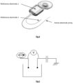
- Fig.4 shows two extracochlear reference electrodes for a possible implementation of a cochlear implant.
- Each of the two extracochlear electrodes has an associated blocking capacitor.
- both extracochlear electrodes are used as reference, simultaneously, hence adding up the effect of the two parallel capacitances C BLO .
- the impedance parameters of the reference electrodes are pragmatically less important than the impedance parameters of the intracochlear electrodes due to their much larger dimensions.
- Other embodiments of cochlear implants may comprise only one large-size extracochlear reference electrode.
- the parameters of the electrical circuit corresponding to the impedance of the electrode-electrolyte interface can be determined by applying the following approach.
- rectangular bi-phasic pulses are generated between two chosen electrodes in the electrode array.
- non-rectangular pulses can be used. Any principally charge balanced pulse type can be envisaged for use in the proposed approach, as long as the pulse does not cause charge transfer towards the tissue that might cause tissue damage.
- the stimulating pulse can be a voltage or a current.
- Fig.5 One possible scheme of the measurement is shown in Fig.5 .
- a current pulse is injected at a stimulating electrode and the voltage responses between the stimulating and the reference electrode(s) are measured at the stimulating electrode (diagonal measurement) as well as between all other electrodes and the reference electrode(s) (off-diagonal measurements).
- the relevant current signal path is illustrated for a diagonal measurement, i.e. a measurement at the stimulating electrode, and in the right-hand part for a non-diagonal measurement, i.e. at any of the non-stimulating contacts of the electrode array.
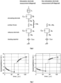
- Voltage responses to the current pulses are recorded at different moments in time during the monopolar biphasic stimulation pulse. For example, a voltage response measurement may be performed for a biphasic pulse at e.g.
- Fig.7 10 instances as illustrated in Fig.7 (for a diagonal measurement on the left and a non-diagonal measurement on the right): at 6, 12, 18, 24, 56 ⁇ s from the leading edge of each of the two pulse phases.
- the left panel shows a typical voltage response measured at the stimulating electrode (diagonal measurement) while the right panel shows the voltage response measured at one of the non-stimulating electrodes of the electrode array (off-diagonal measurements).
- the dots are the measured data, whereas the solid line represents the model fitting of the signal received in response to the stimulation pulse.
- the model parameters can be determined using the following approach.
- the purely resistive components R s contribute to the instantaneous response, i.e. the step-wise behaviour of the waveform near the leading and trailing edges of the stimulation pulse, as can also be seen from Fig.7 .
- the parallel components R F and C DL result in an exponentially decaying/growing time response, as no current is assumed to flow through the electrode-tissue interface at electrodes different from the stimulation electrode.
- the implant-related blocking capacitance C BLO gives rise to a linear slope with time during each phase of the stimulation pulse.
- the blocking capacitance C BLO contributes to both the waveform measured at an electrode different from the intracochlear stimulation electrode (in a non-diagonal measurement) and the waveform at the stimulation electrode itself (diagonal measurement). Because C BLO is common to the recordings at all intracochlear electrodes and because it is the only time-dependent contribution to the off-diagonal measurements, the linear effect of off-diagonal measurements is used to subtract the effect in the diagonal waveforms. This subtraction was already performed in the left panel of Fig.7 . To exclude any effect of the stimulation current, C BLO is preferably determined based on measurements obtained far away from the stimulation electrode. For example, measurements can be used at electrodes at least 18 electrodes away from the stimulating electrode in the array of electrodes.
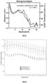
- FIG.8 shows the linearization of the exponential decay of the off-diagonal (non-stimulating electrode) voltage amplitudes allowing for calculating of the R C .
- Fig.9 shows that the median result of the estimation of the T/C fitting parameters (measured behaviourally) over the various electrodes of the array in a number of patients indeed almost exactly agrees with the T/C levels calculated on basis of the correlation with the resistive Faradaic component R F .
- the upper curves in Fig.9 show the differences found for the C levels and the lower curves for the T levels.
- the modiolus is the central part of the cochlea containing the spirally organized neurons of the auditory nerve (spiral ganglion cells). These cells are located in a bony canal called the Rosenthal's canal extending along the medial wall of the cochlear fluid-filled spaces, as illustrated in Fig.11 . It is generally assumed that decreasing the distance from a stimulating contact to the Rosenthal's canal results in lower monopolar current thresholds for neural excitation. When the various intracochlear electrode contacts along the array are considered, a significant correlation in the mathematical model can be demonstrated for the actually measured distances.
- the required calculations in the mathematical model can be performed relying on e.g. a set of behavioural T/C levels, intraoperative electrically-evoked compound action potentials (ECAP) thresholds and cone-beam computed tomography (CBCT) scans.
- ECAP electrically-evoked compound action potentials
- CBCT cone-beam computed tomography
- the patient specific anatomical information is available since CBCT is widely used in cochlear implant patients: preoperatively for visualization of the surgical anatomy and postoperatively in order to evaluate the depth and quality of electrode insertion.
- the location of Rosenthal's canal can be estimated by non-rigidly co-registering a micro-tomography and in-vivo CBCT scans.
- Fig.12 provides an illustration of the agreement between the intraoperative eCAP measurements derived from the electrophysiological Auto-Neural Response Telemetry (Auto-NRT) responses and the distance to the Rosenthal's canal. In the case depicted in Fig.12 the calculated Pearson correlation coefficient is 0,96 (p ⁇ 0,001).
- Prediction of the T/C-levels is also possible on basis of neural responses to the voltage gradients created in the vicinity of the stimulating electrodes.
- Electrophysiological parameters like the electrically-evoked compound action potentials (ECAP), electrically-evoked auditory brainstem responses (EABR) or electrically-evoked stapedius reflex thresholds (ESRT) can serve as basis.
- ECAP electrically-evoked compound action potentials
- ABR electrically-evoked auditory brainstem responses
- ESRT electrically-evoked stapedius reflex thresholds
- cortical and behavioural reactions to the excitation patterns elicited in the auditory pathways can be taken into account.
- Fig.13 shows the average values of the T/C-levels during the fifth fitting session for both prelingually and postlingually implanted patients. Especially for the C levels there exist significant differences between the pre- and postlingual patients with prelingual patients showing higher C levels.
- the etiology of deafness is taken into account.
- Certain etiologies e.g. post-inflammatory cochlear ossification
- the electrophysiological measurements of the level 2 show characteristic abnormalities that have to be considered in the prediction model of the behavioural T/C levels.
- MRI imaging can show decreased diameter of the auditory branch of the cochleovestibular nerve in specific patients that should also be taken into account by the prediction model.
- cortical responses can be measured.
- One or a combination of the following cortical responses can be used:
- Phenomena occurring at this level are once again independent of the cochlear anatomy, electrode positioning or the physiological status of the peripheral nerve fibres. Adding them to the predictive metric in the mathematical model once again helps to improve the prediction quality by explaining additional sources of variability.
- metric can be defined in the mathematical model, whereby some or all of the above-described parameters are combined to allow efficient prediction of the behavioural T/C levels.
- the metric can be calculated using e.g. the deterministic multiple regression or principal components methods, however the use of non-deterministic artificial intelligence algorithms can additionally improve the quality of prediction.
- Al Artificial intelligence
- Al Artificial intelligence
- the initial model is created on basis of the data (input parameters and the T/C-level outcomes) of a number of patients. The metric created on basis of these data is used to predict the behavioural T/C-levels in new patients (not being the part of the model).
Landscapes
- Health & Medical Sciences (AREA)
- Otolaryngology (AREA)
- Life Sciences & Earth Sciences (AREA)
- Animal Behavior & Ethology (AREA)
- Engineering & Computer Science (AREA)
- Biomedical Technology (AREA)
- Nuclear Medicine, Radiotherapy & Molecular Imaging (AREA)
- Radiology & Medical Imaging (AREA)
- Veterinary Medicine (AREA)
- Public Health (AREA)
- General Health & Medical Sciences (AREA)
- Heart & Thoracic Surgery (AREA)
- Cardiology (AREA)
- Prostheses (AREA)
- Electrotherapy Devices (AREA)
- Measurement And Recording Of Electrical Phenomena And Electrical Characteristics Of The Living Body (AREA)
Applications Claiming Priority (2)
| Application Number | Priority Date | Filing Date | Title |
|---|---|---|---|
| US201862678375P | 2018-05-31 | 2018-05-31 | |
| PCT/EP2019/064041 WO2019229162A1 (en) | 2018-05-31 | 2019-05-29 | Method for deriving information for fitting a cochlear implant |
Publications (2)
| Publication Number | Publication Date |
|---|---|
| EP3801740A1 EP3801740A1 (en) | 2021-04-14 |
| EP3801740B1 true EP3801740B1 (en) | 2024-10-16 |
Family
ID=66752087
Family Applications (1)
| Application Number | Title | Priority Date | Filing Date |
|---|---|---|---|
| EP19728384.9A Active EP3801740B1 (en) | 2018-05-31 | 2019-05-29 | Method for deriving information for fitting a cochlear implant |
Country Status (7)
| Country | Link |
|---|---|
| US (1) | US12017070B2 (pl) |
| EP (1) | EP3801740B1 (pl) |
| AU (1) | AU2019276182B2 (pl) |
| DK (1) | DK3801740T3 (pl) |
| ES (1) | ES2998494T3 (pl) |
| PL (1) | PL3801740T3 (pl) |
| WO (1) | WO2019229162A1 (pl) |
Families Citing this family (1)
| Publication number | Priority date | Publication date | Assignee | Title |
|---|---|---|---|---|
| WO2025114819A1 (en) * | 2023-11-27 | 2025-06-05 | Cochlear Limited | Device personalizaton |
Family Cites Families (9)
| Publication number | Priority date | Publication date | Assignee | Title |
|---|---|---|---|---|
| US7835804B2 (en) * | 2006-04-18 | 2010-11-16 | Advanced Bionics, Llc | Removing artifact in evoked compound action potential recordings in neural stimulators |
| US20100106218A1 (en) | 2006-09-14 | 2010-04-29 | Cochlear Limited | Configuration of a stimulation medical implant |
| US9031661B2 (en) | 2010-05-18 | 2015-05-12 | Cochlear Limited | Multi-electrode channel configurations for a hearing prosthesis |
| CN103533986B (zh) | 2011-05-13 | 2016-09-14 | Med-El电气医疗器械有限公司 | 具有通道交互补偿的同时刺激的最佳模型常数 |
| WO2013013265A1 (en) * | 2011-07-28 | 2013-01-31 | The Bionics Institute Of Australia | Device and circuitry for controlling delivery of stimulation signals |
| CN106105266B (zh) * | 2014-03-19 | 2019-06-28 | Med-El电气医疗器械有限公司 | 基于耳蜗植入物中电极阻抗的自动装配映射跟踪 |
| CA2944042C (en) * | 2014-05-05 | 2023-08-29 | Saluda Medical Pty Ltd | Improved neural measurement |
| WO2017100866A1 (en) | 2015-12-18 | 2017-06-22 | Saluda Medical Pty Ltd | Measurement of neural response |
| WO2017182682A1 (es) * | 2016-04-21 | 2017-10-26 | Universidad De Las Palmas De Gran Canaria | Método para la detección automática de fold-over en implantes de porta-electrodos mediante matriz de potenciales |
-
2019
- 2019-05-29 PL PL19728384.9T patent/PL3801740T3/pl unknown
- 2019-05-29 EP EP19728384.9A patent/EP3801740B1/en active Active
- 2019-05-29 US US17/058,467 patent/US12017070B2/en active Active
- 2019-05-29 DK DK19728384.9T patent/DK3801740T3/da active
- 2019-05-29 WO PCT/EP2019/064041 patent/WO2019229162A1/en not_active Ceased
- 2019-05-29 ES ES19728384T patent/ES2998494T3/es active Active
- 2019-05-29 AU AU2019276182A patent/AU2019276182B2/en active Active
Non-Patent Citations (1)
| Title |
|---|
| PEETERS S A ET AL: "Identification of the Impedance Model of an Implanted Cochlear Prosthesis From Intracochlear Potential Measurements", IEEE TRANSACTIONS ON BIOMEDICAL ENGINEERING, IEEE, USA, vol. 51, no. 12, 1 December 2004 (2004-12-01), pages 2174 - 2183, XP011122304, ISSN: 0018-9294, DOI: 10.1109/TBME.2004.836518 * |
Also Published As
| Publication number | Publication date |
|---|---|
| DK3801740T3 (en) | 2025-01-13 |
| AU2019276182A1 (en) | 2020-12-24 |
| WO2019229162A1 (en) | 2019-12-05 |
| WO2019229162A8 (en) | 2020-01-09 |
| EP3801740A1 (en) | 2021-04-14 |
| PL3801740T3 (pl) | 2025-03-17 |
| US20210196954A1 (en) | 2021-07-01 |
| ES2998494T3 (en) | 2025-02-20 |
| US12017070B2 (en) | 2024-06-25 |
| AU2019276182B2 (en) | 2025-04-17 |
Similar Documents
| Publication | Publication Date | Title |
|---|---|---|
| Vanpoucke et al. | Identification of the impedance model of an implanted cochlear prosthesis from intracochlear potential measurements | |
| US20120116741A1 (en) | Systems and methods of constructing a patient specific neural electrical stimulation model | |
| Frijns et al. | Spatial selectivity in a rotationally symmetric model of the electrically stimulated cochlea | |
| Hughes | Objective measures in cochlear implants | |
| US8571675B2 (en) | Determining operating parameters for a stimulating medical device | |
| CN103108671B (zh) | 基于电流的耳蜗植入物的加快适配的方法和系统 | |
| EP2707092B1 (en) | Optimal model constants for simultaneous stimulation with channel interaction compensation | |
| EP3756362B1 (en) | Advanced electrode data analysis | |
| Jiang et al. | An instrumented cochlea model for the evaluation of cochlear implant electrical stimulus spread | |
| US20250135209A1 (en) | Detection and treatment of neotissue | |
| Bruns et al. | Real-time localization of cochlear-implant electrode arrays using bipolar impedance sensing | |
| EP3104931B1 (en) | Determination of neuronal action potential amplitude based on multidimensional differential geometry | |
| WO2024012046A1 (en) | Implantable electrical stimulation (ies) system and method thereof | |
| de Oliveira et al. | Comprehensive decomposition of cochlear implant electrode impedances | |
| US20220072307A1 (en) | Techniques for stimulation artefact elimination | |
| EP3801740B1 (en) | Method for deriving information for fitting a cochlear implant | |
| US20230364421A1 (en) | Parameter optimization based on different degrees of focusing | |
| US20240149056A1 (en) | Electrode physical management technologies | |
| Xia et al. | Estimating user-specific current spread and neural health parameters in a model of hearing with cochlear implants | |
| EP4593023A1 (en) | Method and system for optimizing multipolar stimulation in nerve stimulation protheses | |
| Bruce et al. | Advances in computational modeling of cochlear implant physiology and perception | |
| CN120129908A (zh) | 用于指示神经响应的系统和方法 | |
| PFINGST | Psychophysical Constraints on Biophysical/Neural Models |
Legal Events
| Date | Code | Title | Description |
|---|---|---|---|
| STAA | Information on the status of an ep patent application or granted ep patent |
Free format text: STATUS: UNKNOWN |
|
| STAA | Information on the status of an ep patent application or granted ep patent |
Free format text: STATUS: THE INTERNATIONAL PUBLICATION HAS BEEN MADE |
|
| PUAI | Public reference made under article 153(3) epc to a published international application that has entered the european phase |
Free format text: ORIGINAL CODE: 0009012 |
|
| STAA | Information on the status of an ep patent application or granted ep patent |
Free format text: STATUS: REQUEST FOR EXAMINATION WAS MADE |
|
| 17P | Request for examination filed |
Effective date: 20201215 |
|
| AK | Designated contracting states |
Kind code of ref document: A1 Designated state(s): AL AT BE BG CH CY CZ DE DK EE ES FI FR GB GR HR HU IE IS IT LI LT LU LV MC MK MT NL NO PL PT RO RS SE SI SK SM TR |
|
| AX | Request for extension of the european patent |
Extension state: BA ME |
|
| DAV | Request for validation of the european patent (deleted) | ||
| DAX | Request for extension of the european patent (deleted) | ||
| STAA | Information on the status of an ep patent application or granted ep patent |
Free format text: STATUS: EXAMINATION IS IN PROGRESS |
|
| 17Q | First examination report despatched |
Effective date: 20230313 |
|
| GRAP | Despatch of communication of intention to grant a patent |
Free format text: ORIGINAL CODE: EPIDOSNIGR1 |
|
| STAA | Information on the status of an ep patent application or granted ep patent |
Free format text: STATUS: GRANT OF PATENT IS INTENDED |
|
| INTG | Intention to grant announced |
Effective date: 20240619 |
|
| GRAS | Grant fee paid |
Free format text: ORIGINAL CODE: EPIDOSNIGR3 |
|
| GRAA | (expected) grant |
Free format text: ORIGINAL CODE: 0009210 |
|
| STAA | Information on the status of an ep patent application or granted ep patent |
Free format text: STATUS: THE PATENT HAS BEEN GRANTED |
|
| AK | Designated contracting states |
Kind code of ref document: B1 Designated state(s): AL AT BE BG CH CY CZ DE DK EE ES FI FR GB GR HR HU IE IS IT LI LT LU LV MC MK MT NL NO PL PT RO RS SE SI SK SM TR |
|
| RAP3 | Party data changed (applicant data changed or rights of an application transferred) |
Owner name: ENTIC RESEARCH AND TRAINING CENTER BV |
|
| REG | Reference to a national code |
Ref country code: GB Ref legal event code: FG4D |
|
| REG | Reference to a national code |
Ref country code: CH Ref legal event code: EP |
|
| REG | Reference to a national code |
Ref country code: IE Ref legal event code: FG4D |
|
| REG | Reference to a national code |
Ref country code: DE Ref legal event code: R096 Ref document number: 602019060463 Country of ref document: DE |
|
| REG | Reference to a national code |
Ref country code: DK Ref legal event code: T3 Effective date: 20250108 |
|
| REG | Reference to a national code |
Ref country code: SE Ref legal event code: TRGR |
|
| REG | Reference to a national code |
Ref country code: NL Ref legal event code: FP |
|
| REG | Reference to a national code |
Ref country code: LT Ref legal event code: MG9D |
|
| REG | Reference to a national code |
Ref country code: ES Ref legal event code: FG2A Ref document number: 2998494 Country of ref document: ES Kind code of ref document: T3 Effective date: 20250220 |
|
| PG25 | Lapsed in a contracting state [announced via postgrant information from national office to epo] |
Ref country code: PT Free format text: LAPSE BECAUSE OF FAILURE TO SUBMIT A TRANSLATION OF THE DESCRIPTION OR TO PAY THE FEE WITHIN THE PRESCRIBED TIME-LIMIT Effective date: 20250217 Ref country code: IS Free format text: LAPSE BECAUSE OF FAILURE TO SUBMIT A TRANSLATION OF THE DESCRIPTION OR TO PAY THE FEE WITHIN THE PRESCRIBED TIME-LIMIT Effective date: 20250216 Ref country code: HR Free format text: LAPSE BECAUSE OF FAILURE TO SUBMIT A TRANSLATION OF THE DESCRIPTION OR TO PAY THE FEE WITHIN THE PRESCRIBED TIME-LIMIT Effective date: 20241016 |
|
| PG25 | Lapsed in a contracting state [announced via postgrant information from national office to epo] |
Ref country code: FI Free format text: LAPSE BECAUSE OF FAILURE TO SUBMIT A TRANSLATION OF THE DESCRIPTION OR TO PAY THE FEE WITHIN THE PRESCRIBED TIME-LIMIT Effective date: 20241016 |
|
| PG25 | Lapsed in a contracting state [announced via postgrant information from national office to epo] |
Ref country code: BG Free format text: LAPSE BECAUSE OF FAILURE TO SUBMIT A TRANSLATION OF THE DESCRIPTION OR TO PAY THE FEE WITHIN THE PRESCRIBED TIME-LIMIT Effective date: 20241016 |
|
| PG25 | Lapsed in a contracting state [announced via postgrant information from national office to epo] |
Ref country code: NO Free format text: LAPSE BECAUSE OF FAILURE TO SUBMIT A TRANSLATION OF THE DESCRIPTION OR TO PAY THE FEE WITHIN THE PRESCRIBED TIME-LIMIT Effective date: 20250116 |
|
| PG25 | Lapsed in a contracting state [announced via postgrant information from national office to epo] |
Ref country code: LV Free format text: LAPSE BECAUSE OF FAILURE TO SUBMIT A TRANSLATION OF THE DESCRIPTION OR TO PAY THE FEE WITHIN THE PRESCRIBED TIME-LIMIT Effective date: 20241016 Ref country code: GR Free format text: LAPSE BECAUSE OF FAILURE TO SUBMIT A TRANSLATION OF THE DESCRIPTION OR TO PAY THE FEE WITHIN THE PRESCRIBED TIME-LIMIT Effective date: 20250117 |
|
| PG25 | Lapsed in a contracting state [announced via postgrant information from national office to epo] |
Ref country code: RS Free format text: LAPSE BECAUSE OF FAILURE TO SUBMIT A TRANSLATION OF THE DESCRIPTION OR TO PAY THE FEE WITHIN THE PRESCRIBED TIME-LIMIT Effective date: 20250116 |
|
| PGFP | Annual fee paid to national office [announced via postgrant information from national office to epo] |
Ref country code: NL Payment date: 20250521 Year of fee payment: 7 |
|
| PG25 | Lapsed in a contracting state [announced via postgrant information from national office to epo] |
Ref country code: SM Free format text: LAPSE BECAUSE OF FAILURE TO SUBMIT A TRANSLATION OF THE DESCRIPTION OR TO PAY THE FEE WITHIN THE PRESCRIBED TIME-LIMIT Effective date: 20241016 |
|
| PGFP | Annual fee paid to national office [announced via postgrant information from national office to epo] |
Ref country code: PL Payment date: 20250422 Year of fee payment: 7 Ref country code: DE Payment date: 20250521 Year of fee payment: 7 |
|
| PGFP | Annual fee paid to national office [announced via postgrant information from national office to epo] |
Ref country code: DK Payment date: 20250526 Year of fee payment: 7 |
|
| PGFP | Annual fee paid to national office [announced via postgrant information from national office to epo] |
Ref country code: LU Payment date: 20250521 Year of fee payment: 7 Ref country code: IT Payment date: 20250527 Year of fee payment: 7 Ref country code: BE Payment date: 20250521 Year of fee payment: 7 |
|
| REG | Reference to a national code |
Ref country code: DE Ref legal event code: R097 Ref document number: 602019060463 Country of ref document: DE |
|
| PG25 | Lapsed in a contracting state [announced via postgrant information from national office to epo] |
Ref country code: EE Free format text: LAPSE BECAUSE OF FAILURE TO SUBMIT A TRANSLATION OF THE DESCRIPTION OR TO PAY THE FEE WITHIN THE PRESCRIBED TIME-LIMIT Effective date: 20241016 |
|
| PGFP | Annual fee paid to national office [announced via postgrant information from national office to epo] |
Ref country code: FR Payment date: 20250528 Year of fee payment: 7 |
|
| PGFP | Annual fee paid to national office [announced via postgrant information from national office to epo] |
Ref country code: CH Payment date: 20250601 Year of fee payment: 7 |
|
| PG25 | Lapsed in a contracting state [announced via postgrant information from national office to epo] |
Ref country code: RO Free format text: LAPSE BECAUSE OF FAILURE TO SUBMIT A TRANSLATION OF THE DESCRIPTION OR TO PAY THE FEE WITHIN THE PRESCRIBED TIME-LIMIT Effective date: 20241016 |
|
| PGFP | Annual fee paid to national office [announced via postgrant information from national office to epo] |
Ref country code: AT Payment date: 20250522 Year of fee payment: 7 |
|
| PG25 | Lapsed in a contracting state [announced via postgrant information from national office to epo] |
Ref country code: SK Free format text: LAPSE BECAUSE OF FAILURE TO SUBMIT A TRANSLATION OF THE DESCRIPTION OR TO PAY THE FEE WITHIN THE PRESCRIBED TIME-LIMIT Effective date: 20241016 |
|
| PG25 | Lapsed in a contracting state [announced via postgrant information from national office to epo] |
Ref country code: CZ Free format text: LAPSE BECAUSE OF FAILURE TO SUBMIT A TRANSLATION OF THE DESCRIPTION OR TO PAY THE FEE WITHIN THE PRESCRIBED TIME-LIMIT Effective date: 20241016 |
|
| PGFP | Annual fee paid to national office [announced via postgrant information from national office to epo] |
Ref country code: SE Payment date: 20250521 Year of fee payment: 7 |
|
| PLBE | No opposition filed within time limit |
Free format text: ORIGINAL CODE: 0009261 |
|
| STAA | Information on the status of an ep patent application or granted ep patent |
Free format text: STATUS: NO OPPOSITION FILED WITHIN TIME LIMIT |
|
| 26N | No opposition filed |
Effective date: 20250717 |
|
| PGFP | Annual fee paid to national office [announced via postgrant information from national office to epo] |
Ref country code: ES Payment date: 20250630 Year of fee payment: 7 |
|
| GBPC | Gb: european patent ceased through non-payment of renewal fee |
Effective date: 20250529 |
|
| PG25 | Lapsed in a contracting state [announced via postgrant information from national office to epo] |
Ref country code: MC Free format text: LAPSE BECAUSE OF FAILURE TO SUBMIT A TRANSLATION OF THE DESCRIPTION OR TO PAY THE FEE WITHIN THE PRESCRIBED TIME-LIMIT Effective date: 20241016 |
|
| REG | Reference to a national code |
Ref country code: AT Ref legal event code: UEP Ref document number: 1732456 Country of ref document: AT Kind code of ref document: T Effective date: 20241016 |