EP3801698B1 - Spritze mit niedriger dosis mit einem entlüftungssystem - Google Patents
Spritze mit niedriger dosis mit einem entlüftungssystem Download PDFInfo
- Publication number
- EP3801698B1 EP3801698B1 EP19728275.9A EP19728275A EP3801698B1 EP 3801698 B1 EP3801698 B1 EP 3801698B1 EP 19728275 A EP19728275 A EP 19728275A EP 3801698 B1 EP3801698 B1 EP 3801698B1
- Authority
- EP
- European Patent Office
- Prior art keywords
- chamber
- stopper
- sidewall portion
- barrel
- air
- Prior art date
- Legal status (The legal status is an assumption and is not a legal conclusion. Google has not performed a legal analysis and makes no representation as to the accuracy of the status listed.)
- Active
Links
Images


Classifications
-
- A—HUMAN NECESSITIES
- A61—MEDICAL OR VETERINARY SCIENCE; HYGIENE
- A61M—DEVICES FOR INTRODUCING MEDIA INTO, OR ONTO, THE BODY; DEVICES FOR TRANSDUCING BODY MEDIA OR FOR TAKING MEDIA FROM THE BODY; DEVICES FOR PRODUCING OR ENDING SLEEP OR STUPOR
- A61M5/00—Devices for bringing media into the body in a subcutaneous, intra-vascular or intramuscular way; Accessories therefor, e.g. filling or cleaning devices, arm-rests
- A61M5/178—Syringes
- A61M5/31—Details
- A61M5/3129—Syringe barrels
- A61M5/3135—Syringe barrels characterised by constructional features of the proximal end
-
- A—HUMAN NECESSITIES
- A61—MEDICAL OR VETERINARY SCIENCE; HYGIENE
- A61M—DEVICES FOR INTRODUCING MEDIA INTO, OR ONTO, THE BODY; DEVICES FOR TRANSDUCING BODY MEDIA OR FOR TAKING MEDIA FROM THE BODY; DEVICES FOR PRODUCING OR ENDING SLEEP OR STUPOR
- A61M5/00—Devices for bringing media into the body in a subcutaneous, intra-vascular or intramuscular way; Accessories therefor, e.g. filling or cleaning devices, arm-rests
- A61M5/178—Syringes
-
- A—HUMAN NECESSITIES
- A61—MEDICAL OR VETERINARY SCIENCE; HYGIENE
- A61M—DEVICES FOR INTRODUCING MEDIA INTO, OR ONTO, THE BODY; DEVICES FOR TRANSDUCING BODY MEDIA OR FOR TAKING MEDIA FROM THE BODY; DEVICES FOR PRODUCING OR ENDING SLEEP OR STUPOR
- A61M5/00—Devices for bringing media into the body in a subcutaneous, intra-vascular or intramuscular way; Accessories therefor, e.g. filling or cleaning devices, arm-rests
- A61M5/178—Syringes
- A61M5/1782—Devices aiding filling of syringes in situ
-
- A—HUMAN NECESSITIES
- A61—MEDICAL OR VETERINARY SCIENCE; HYGIENE
- A61M—DEVICES FOR INTRODUCING MEDIA INTO, OR ONTO, THE BODY; DEVICES FOR TRANSDUCING BODY MEDIA OR FOR TAKING MEDIA FROM THE BODY; DEVICES FOR PRODUCING OR ENDING SLEEP OR STUPOR
- A61M5/00—Devices for bringing media into the body in a subcutaneous, intra-vascular or intramuscular way; Accessories therefor, e.g. filling or cleaning devices, arm-rests
- A61M5/178—Syringes
- A61M5/31—Details
- A61M5/315—Pistons; Piston-rods; Guiding, blocking or restricting the movement of the rod or piston; Appliances on the rod for facilitating dosing ; Dosing mechanisms
- A61M5/31511—Piston or piston-rod constructions, e.g. connection of piston with piston-rod
-
- A—HUMAN NECESSITIES
- A61—MEDICAL OR VETERINARY SCIENCE; HYGIENE
- A61M—DEVICES FOR INTRODUCING MEDIA INTO, OR ONTO, THE BODY; DEVICES FOR TRANSDUCING BODY MEDIA OR FOR TAKING MEDIA FROM THE BODY; DEVICES FOR PRODUCING OR ENDING SLEEP OR STUPOR
- A61M5/00—Devices for bringing media into the body in a subcutaneous, intra-vascular or intramuscular way; Accessories therefor, e.g. filling or cleaning devices, arm-rests
- A61M5/36—Devices for bringing media into the body in a subcutaneous, intra-vascular or intramuscular way; Accessories therefor, e.g. filling or cleaning devices, arm-rests with means for eliminating or preventing injection or infusion of air into body
-
- A—HUMAN NECESSITIES
- A61—MEDICAL OR VETERINARY SCIENCE; HYGIENE
- A61M—DEVICES FOR INTRODUCING MEDIA INTO, OR ONTO, THE BODY; DEVICES FOR TRANSDUCING BODY MEDIA OR FOR TAKING MEDIA FROM THE BODY; DEVICES FOR PRODUCING OR ENDING SLEEP OR STUPOR
- A61M5/00—Devices for bringing media into the body in a subcutaneous, intra-vascular or intramuscular way; Accessories therefor, e.g. filling or cleaning devices, arm-rests
- A61M5/178—Syringes
- A61M5/31—Details
- A61M2005/3123—Details having air entrapping or venting means, e.g. purging channels in pistons
-
- A—HUMAN NECESSITIES
- A61—MEDICAL OR VETERINARY SCIENCE; HYGIENE
- A61M—DEVICES FOR INTRODUCING MEDIA INTO, OR ONTO, THE BODY; DEVICES FOR TRANSDUCING BODY MEDIA OR FOR TAKING MEDIA FROM THE BODY; DEVICES FOR PRODUCING OR ENDING SLEEP OR STUPOR
- A61M2205/00—General characteristics of the apparatus
- A61M2205/33—Controlling, regulating or measuring
- A61M2205/3379—Masses, volumes, levels of fluids in reservoirs, flow rates
-
- A—HUMAN NECESSITIES
- A61—MEDICAL OR VETERINARY SCIENCE; HYGIENE
- A61M—DEVICES FOR INTRODUCING MEDIA INTO, OR ONTO, THE BODY; DEVICES FOR TRANSDUCING BODY MEDIA OR FOR TAKING MEDIA FROM THE BODY; DEVICES FOR PRODUCING OR ENDING SLEEP OR STUPOR
- A61M2207/00—Methods of manufacture, assembly or production
-
- A—HUMAN NECESSITIES
- A61—MEDICAL OR VETERINARY SCIENCE; HYGIENE
- A61M—DEVICES FOR INTRODUCING MEDIA INTO, OR ONTO, THE BODY; DEVICES FOR TRANSDUCING BODY MEDIA OR FOR TAKING MEDIA FROM THE BODY; DEVICES FOR PRODUCING OR ENDING SLEEP OR STUPOR
- A61M2209/00—Ancillary equipment
- A61M2209/04—Tools for specific apparatus
- A61M2209/045—Tools for specific apparatus for filling, e.g. for filling reservoirs
-
- A—HUMAN NECESSITIES
- A61—MEDICAL OR VETERINARY SCIENCE; HYGIENE
- A61M—DEVICES FOR INTRODUCING MEDIA INTO, OR ONTO, THE BODY; DEVICES FOR TRANSDUCING BODY MEDIA OR FOR TAKING MEDIA FROM THE BODY; DEVICES FOR PRODUCING OR ENDING SLEEP OR STUPOR
- A61M5/00—Devices for bringing media into the body in a subcutaneous, intra-vascular or intramuscular way; Accessories therefor, e.g. filling or cleaning devices, arm-rests
- A61M5/178—Syringes
- A61M5/31—Details
- A61M5/315—Pistons; Piston-rods; Guiding, blocking or restricting the movement of the rod or piston; Appliances on the rod for facilitating dosing ; Dosing mechanisms
- A61M5/31511—Piston or piston-rod constructions, e.g. connection of piston with piston-rod
- A61M5/31513—Piston constructions to improve sealing or sliding
Definitions
- aspects of the present disclosure relate to medical devices capable of evacuating air trapped within the medical device while filling the medical device with liquid.
- WO 03/028785 A2 disclose further background art for the present invention.
- WO 96/30066 A1 disclose further background art for the present invention.
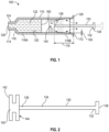
- Exemplary syringe barrels described herein include a side wall having an interior surface defining a chamber for retaining fluid, an open proximal end and a distal end including a distal wall with a tip extending distally therefrom having an open passageway in fluid communication with said chamber.
- the medical devices include a plunger rod and stopper disposed within the chamber of the syringe barrels or other containers.
- a first aspect of the present disclosure pertains to a medical device including a syringe barrel having an open proximal end, a distal end and a distal wall.
- a sidewall extends from the distal end to the open proximal end and includes an interior surface that defines a chamber for retaining or holding fluids, which may include liquid medication and/or other liquids.
- a tip extending distally from the distal wall. The tip having an open passageway there through in fluid communication with the chamber.
- the medical device also includes a plunger rod having a proximal end, a distal end and a body extending from the proximal end to the distal end.
- the plunger rod is disposed within the chamber and moveable in the proximal and distal direction within the chamber.
- the medical device also includes a stopper having a distal face and a proximal end.
- the stopper is attached to the plunger rod.
- the stopper is disposed within the chamber and moveable in the proximal and distal direction within the chamber.
- Sidewall of the syringe barrel includes a first sidewall portion and a second sidewall portion.
- First sidewall portion is disposed at the distal end of the barrel.
- First sidewall portion has an inner diameter equal to or smaller than an outer diameter of the stopper to form a releasable fluid-tight seal between the stopper and the interior surface of the sidewall of the barrel.
- Second sidewall portion is disposed at the open proximal end of the barrel.
- Second sidewall portion includes a taper.
- Second sidewall portion has an inner diameter larger than the outer diameter of the stopper forming a gap between the interior surface of the sidewall and stopper causing the releasable seal between the stopper and the sidewall of the barrel to break thereby permitting air to vent from the chamber while preventing liquid from exiting the chamber.
- the inner diameter of the second sidewall portion increases gradually in the proximal direction.
- the distal end of the plunger rod is disposed within the barrel and the stopper forms a releasable seal with the sidewall of the barrel having an inner diameter equal to or smaller than the outer diameter of the stopper.
- the releasable fluid-tight seal between the stopper and the interior surface of the sidewall of the barrel is broken when the stopper reaches the taper of the second sidewall portion at the open proximal end of the barrel.
- the releasable seal upon movement of the plunger rod in a distal direction relative to the taper of the second sidewall portion at the open proximal end of the barrel, the releasable seal is re-formed allowing the fluid within the chamber to be expelled through the open passageway of the tip in fluid communication with said chamber.
- medical device includes a barrel graduation line.
- the second sidewall portion is proximal to the barrel graduation line.
- Another aspect of the present disclosure pertains to a method for filling a syringe barrel with a liquid including providing a medical device of the as described herein.
- the tip of the syringe barrel is submerged in a liquid and an air source and the liquid is drawn into the chamber prior to reaching the tapered sidewall of the barrel.
- the air source is evacuated from the chamber by moving the plunger rod in a proximal direction past the second sidewall portion of the barrel to allow the stopper to break the releasable fluid-tight seal between the stopper and the interior surface of the sidewall of the barrel when the stopper reaches the gap formed by the second sidewall portion for permitting air to vent from the chamber and preventing liquid from exiting the chamber.
- the releasable fluid-tight seal is re-formed upon contact of the stopper with the first sidewall portion allowing the fluid within the chamber to be expelled through the open passageway of the tip in fluid communication with said chamber.
- a medical device including a syringe barrel including a sidewall having an interior surface defining a chamber for retaining a liquid, an open proximal end, a distal end including a distal wall with a tip extending distally therefrom having an open passageway in fluid communication with said chamber.
- the sidewall includes a first sidewall portion and a second sidewall portion.
- the medical device includes a plunger rod having a proximal end, a distal end and a body extending from the proximal end to the distal end.
- the plunger rod is disposed within the chamber and is moveable in the proximal and distal direction within the chamber.
- the medical device includes a stopper disposed within the chamber.
- the stopper includes a distal face and a proximal end.
- the stopper is moveable in the proximal and distal direction within the chamber.
- the distal end of the barrel includes the first sidewall portion to form a releasable fluid-tight seal between the stopper and the interior surface of the first sidewall portion of the barrel.
- the open proximal end of the barrel includes the second sidewall portion having one air venting groove embedded within the second sidewall portion of the barrel to break the releasable seal between the stopper and the sidewall of the barrel for permitting air to vent from the chamber and preventing liquid from exiting the chamber.
- the open proximal end of the barrel includes the second sidewall portion including a plurality of air venting grooves embedded within the second sidewall portion of the barrel to break the releasable seal between the stopper and the sidewall of the barrel for permitting air to vent from the chamber and preventing liquid from exiting the chamber.
- the stopper forms a releasable fluid-tight seal with the first sidewall portion of the barrel when the distal end of the plunger rod is disposed within the first sidewall portion.
- the stopper breaks the releasable fluid-tight seal between the stopper and the first sidewall portion of the barrel when the distal end of the plunger rod is disposed within the second sidewall portion.
- the releasable fluid-tight seal is re-formed upon contact of the stopper with the first sidewall portion allowing the fluid within the chamber to be expelled through the open passageway of the tip in fluid communication with said chamber.
- Another aspect of the present disclosure pertains to a method for filling a syringe barrel with liquid, including providing a medical device as described herein.
- the tip of the syringe barrel is submerged in a liquid and an air source and the liquid are drawn into the chamber prior to reaching the plurality of air venting grooves embedded within the second sidewall portion of the barrel.
- the air source is evacuated from the chamber by moving the plunger rod in a proximal direction past the plurality of air venting grooves embedded within the second sidewall portion of the barrel to allow the stopper to break the releasable fluid-tight seal between the stopper and the interior surface of the first sidewall portion of the barrel for permitting air to vent from the chamber and preventing liquid from exiting the chamber.
- the releasable fluid-tight seal is re-formed upon contact of the stopper with the first sidewall portion allowing the fluid within the chamber to be expelled through the open passageway of the tip in fluid communication with said chamber.
- a medical device including a syringe barrel having a sidewall having an interior surface defining a chamber for retaining a liquid, an open proximal end and a distal end including a distal wall with a tip extending distally therefrom having an open passageway in fluid communication with said chamber.
- the sidewall having a first sidewall portion and a second sidewall portion.
- a plunger rod including a proximal end, a distal end and a body extending from the proximal end to the distal end.
- the plunger rod disposed within the chamber and moveable in the proximal and distal direction within the chamber.
- a stopper disposed within the chamber and moveable in the proximal and distal direction within the chamber, the stopper having a stopper including a distal face, a proximal end.
- the distal end of the barrel includes the first sidewall portion to form a releasable fluid-tight seal between the stopper and the interior surface of the first sidewall portion of the barrel.
- the open proximal end of the barrel includes the second sidewall portion including a plurality of air venting grooves embedded within the interior surface of the second sidewall portion of the barrel to break the releasable seal between the stopper and the sidewall of the barrel.
- a porous membrane is disposed over the plurality of air venting grooves to permit air to flow out of the chamber and to prevent liquid from exiting the chamber.
- the interior surface 420 of the syringe barrel 410 may have a smooth surface that is free of any protrusions or depressions.
- a plunger rod 430 and a stopper 440 are inserted into the open proximal end 412 of the syringe barrel 410.
- stopper 440 having a distal end 441 having a distal face 442 and a proximal end 444.
- the stopper 440 is disposed within the chamber 422 and is moveable in the proximal and distal direction within the chamber 422, the stopper 440 forming a fluid-tight seal with the interior surface of the syringe barrel 410.
- the stopper 440 includes an outside surface and an interior surface defining a channel 445 within the body extending from the distal end 441 to the proximal end 444 for venting air.
- the distal face 442 has an opening 447 in fluid communication with channel 445.
- the channel 445 within the stopper has a depth, shape or cross-sectional width that allows the air within the barrel to escape through the channel 445.
- the porous plug 449 of the embodiments of the medical devices described herein may include a selective barrier that defines a liquid penetration pressure and an air penetration pressure that is less than the liquid penetration pressure.
- the porous plug 449 may include a hydrophilic filter, a hydrophobic filter, a swellable polymer and/or other suitable materials that are air permeable and liquid impermeable and/or combinations thereof.
- suitable hydrophilic filters include hydrophilic polytetrafluoroethylene membrane filters. Such filters are available from the W. L. Gore & Associates of Elkton, Maryland.
- suitable hydrophobic filters include a material known under the trademark "Tyvek" produced by E. I. duPont de Nemours and Company, Inc.
- Suitable hydrophobic filters resist liquid from wicking through the filter at a reasonable pressure gradient.
- the hydrophobic filter has a water penetration pressure, or the pressure at which water permeates or penetrates the hydrophobic filter that is greater than the air penetration pressure, or the pressure at which air permeates or penetrates the hydrophobic filter.
- the water penetration pressure of the hydrophobic filter is greater than a vacuum pressure generated within the chamber of the syringe barrel or other containers and/or within the stopper and plunger rod assemblies described herein.
- This difference in pressure creates a pressure differential across the porous portion that drives air and liquid toward the porous portion, with the liquid impermeable property of the porous portion preventing liquid from permeating through the porous portion and allowing air to permeate through the porous portion.
- the porous plug 449 may be shaped and positioned to occupy a portion of the distal face of the stopper to provide an evacuation system for the air within the syringe barrel to escape without interfering with the ability of the stopper or plunger rod to form a seal with the syringe barrel.
- the porous plug 449 may be shaped and positioned to occupy the opening of the distal face 442 and is in fluid communication with channel 445 of the stopper 440.
- the porous plug 449 is air permeable and liquid impermeable.
- the porous plug 449 comprises a selective barrier having a liquid penetration pressure and an air penetration pressure that is less than the liquid penetration pressure.
- the porous plug 449 may be integrally formed on the distal face 442, with the peripheral edges of the distal face 442 and the body of the stopper remaining non-porous.
- the porous plug 449 may also be shaped to fit within the opening 447.
- the porous plug 449 may extend from the distal face 442 into the channel 445.
- the porous plug 449 may have a periphery that is molded to a portion of the distal face 442.
- the porous plug 449 may be attached to the distal face 442 of the stopper by mechanical means, for example, adhesives and/or molding.
- the distal face 442 may include a pocket (not shown) for holding and securing the porous plug 449 adjacent to the distal face 442 and the opening 447 such that the porous plug 449 is in fluid communication with channel 445.
- the porous plug 449 may be shaped and positioned to occupy the opening of the distal face 442 and is in fluid communication with channel 445 of the stopper 440.
- Plunger cap 450 is inserted in a portion of the channel 438 at the proximal end 432 of plunger rod 430 during filling of the syringe an dispensing. Plunger cap 450 is removed from the channel 438 at the proximal end 432 of plunger rod 430 during venting of air from the chamber 422.
- the plunger cap 450 can be designed as push button such that the air venting path in the channel 438 can be opened and closed with pushing on the plunger cap 450.
- the plunger cap 450 may be formed from an elastomeric material, polymeric material or other material known in the art.
Landscapes
- Health & Medical Sciences (AREA)
- Vascular Medicine (AREA)
- Engineering & Computer Science (AREA)
- Anesthesiology (AREA)
- Biomedical Technology (AREA)
- Heart & Thoracic Surgery (AREA)
- Hematology (AREA)
- Life Sciences & Earth Sciences (AREA)
- Animal Behavior & Ethology (AREA)
- General Health & Medical Sciences (AREA)
- Public Health (AREA)
- Veterinary Medicine (AREA)
- Emergency Medicine (AREA)
- Infusion, Injection, And Reservoir Apparatuses (AREA)
Claims (7)
- Medizinische Vorrichtung, die aufweist:einen Spritzenzylinder (110, 310), der eine Seitenwand (118, 218, 318, 418) aufweist mit einer Innenfläche (120, 220, 320, 420), die eine Kammer (122, 222, 322, 422) zum Zurückhalten einer Flüssigkeit definiert, einem offenen proximalen Ende (112, 212, 312, 412) und einem distalen Ende (114, 214, 314, 414), das eine distale Wand (116, 216, 316, 416) mit einer Spitze (124, 224, 324, 424) aufweist, die sich distal davon erstreckt und einen offenen Durchgang (126, 226, 326, 426) in Fluidverbindung mit der Kammer (122, 222, 322, 422) aufweist, wobei die Seitenwand (118, 218, 318, 418) einen ersten Seitenwandabschnitt (118A, 218A, 318A) und einen zweiten Seitenwandabschnitt (118B, 218B, 318B) aufweist;eine Kolbenstange (130, 230, 330, 430), die ein proximales Ende (132, 232, 332, 432), ein distales Ende (136, 236, 336, 426) und einen Körper (134, 234, 334, 434) aufweist, der sich von dem proximalen Ende (132, 232, 332, 432) zu dem distalen Ende (136, 236, 336, 436) erstreckt, wobei die Kolbenstange (130, 230, 330, 430) in der Kammer (122, 222, 322, 422) angeordnet ist und in der proximalen und distalen Richtung in der Kammer (122, 222, 322, 422) bewegbar ist;einen Stopfen (140, 240, 340, 440), der in der Kammer (122, 222, 322, 422) angeordnet ist und in der proximalen und distalen Richtung in der Kammer (122, 222, 322, 422) bewegbar ist, wobei der Stopfen (140, 240, 340, 440) einen Stopfen (140, 240, 340, 440) aufweist, der eine distale Fläche (242, 342, 442) und ein proximales Ende (144, 244, 344, 444) aufweist; und wobei das distale Ende (114, 214, 314, 414) des Zylinders (110, 310) den ersten Seitenwandabschnitt (118A, 218A, 318A) aufweist, um eine lösbare fluiddichte Abdichtung zwischen dem Stopfen (140, 240, 340, 440) und der Innenfläche (120, 220, 320, 420) des ersten Seitenwandabschnitts (118A, 218A, 318A) des Zylinders (110, 310) zu bilden,dadurch gekennzeichnet, dassdas offene proximale Ende (112, 212, 312, 412) des Zylinders (110, 310) den zweiten Seitenwandabschnitt (118A, 218B, 318B) aufweist, der eine Vielzahl von Entlüftungsnuten (280, 380) aufweist, die in der Innenfläche (120, 220, 320, 420) des zweiten Seitenwandabschnitts (118B, 218B, 318B) des Zylinders (110, 310) eingebettet sind, um die lösbare fluiddichte Abdichtung zwischen dem Stopfen (140, 240, 340, 440) und der Seitenwand (118, 218, 318, 418) des Zylinders (110, 310) zu brechen; undeine poröse Membran (390) über der Vielzahl von Lüftungsnuten (280, 380) angeordnet ist, um zu ermöglichen, dass Luft aus der Kammer (122, 222, 322, 422) ausströmt, und um zu verhindern, dass Flüssigkeit aus der Kammer (122, 222, 322, 422) austritt, wobei sich die poröse Membran (390), die über der Vielzahl von Entlüftungsnuten (280, 380) angeordnet ist, in einer Richtung im Wesentlichen parallel zu einer Längsrichtung der Kammer (122, 222, 322, 422) erstreckt.
- Medizinische Vorrichtung nach Anspruch 1, wobei der Stopfen (140, 240, 340, 440) eine lösbare fluiddichte Abdichtung mit dem ersten Seitenwandabschnitt (118A, 218A, 318A) des Zylinders (110, 310) bildet, wenn das distale Ende (136, 236, 336, 436) der Kolbenstange (130, 230, 330, 430) in dem ersten Seitenwandabschnitt (118A, 218A, 418A) angeordnet ist.
- Medizinische Vorrichtung nach Anspruch 2, wobei der Stopfen (140, 240, 340, 440) die lösbare fluiddichte Abdichtung zwischen dem Stopfen (140, 240, 340, 440) und dem ersten Seitenwandabschnitt (118A, 218A, 318A) des Zylinders (110, 310) bricht, wenn das distale Ende (136, 236, 336, 436) der Kolbenstange (130, 230, 330, 430) über die poröse Membran (390) bewegt wird, die über der Vielzahl von Entlüftungsnuten (280, 380) des zweiten Seitenwandabschnitts (118B, 218B, 318B) angeordnet ist.
- Medizinische Vorrichtung nach Anspruch 3, wobei bei Bewegung der Kolbenstange (130, 230, 330, 430) in einer distalen Richtung ausgehend von dem zweiten Seitenwandabschnitt (118B, 218B, 318B) in Richtung des ersten Seitenwandabschnitts (118A, 218A, 418A) die lösbare fluiddichte Abdichtung bei Kontakt des Stopfens (140, 240, 340, 440) mit dem ersten Seitenwandabschnitt (118A, 218A, 318A) neu gebildet wird, wodurch die Flüssigkeit in der Kammer (122, 222, 322, 422) durch den offenen Durchgang (126, 226, 326, 426) der Spitze (124, 224, 324, 424) in Fluidverbindung mit der Kammer (122, 222, 322, 422) ausgestoßen werden kann.
- Medizinische Vorrichtung nach Anspruch 1, wobei die poröse Membran (390), die über der Vielzahl von Entlüftungsnuten (280, 380) angeordnet ist, entlang eines Abschnitts des zweiten Seitenwandabschnitts (118B, 218B, 318B) angeordnet ist.
- Medizinische Vorrichtung nach Anspruch 1, wobei die poröse Membran (390), die über der Vielzahl von Entlüftungsnuten (280, 380) angeordnet ist, entlang einer Gesamtlänge des zweiten Seitenwandabschnitts (118B, 218B, 318B) angeordnet ist.
- Verfahren zum Befüllen einer medizinischen Vorrichtung mit Flüssigkeit, das umfasst:Bereitstellen der medizinischen Vorrichtung nach Anspruch 1;Eintauchen der Spitze (124, 224, 324, 424) des Spritzenzylinders (110, 310) in eine Flüssigkeit;Aufziehen einer Luftquelle und der Flüssigkeit in die Kammer (122, 222, 322, 422) vor dem Erreichen der Vielzahl von Entlüftungsnuten (280, 380), die in dem zweiten Seitenwandabschnitt (118B, 218B, 318B) des Zylinders (110, 310) eingebettet sind;Evakuieren der Luftquelle aus der Kammer (122, 222, 322, 422) durch Bewegen der Kolbenstange (130, 320, 330, 430) in einer proximalen Richtung an der porösen Membran (390) vorbei, die über der Vielzahl von Entlüftungsnuten (280, 380) angeordnet ist, die in dem zweiten Seitenwandabschnitt (118B, 218B, 318B) des Zylinders (110, 310) eingebettet sind, damit der Stopfen (140, 240, 340, 440) die lösbare fluiddichte Abdichtung zwischen dem Stopfen (140, 240, 340, 440) und der Innenfläche (120, 220, 320, 420) des ersten Seitenwandabschnitts (118A, 218A, 318A) des Zylinders (110, 310) brechen kann, um eine Entlüftung der Kammer (122, 222, 322, 422) zu ermöglichen und ein Austreten von Flüssigkeit aus der Kammer (122, 222, 322, 422) zu verhindern; undNeubilden der lösbaren fluiddichten Abdichtung bei Kontakt des Stopfens (140, 240, 340, 440) mit dem ersten Seitenwandabschnitt, wodurch die Flüssigkeit in der Kammer (122, 222, 322, 422) durch den offenen Durchgang (126, 226, 326, 426) der Spitze (124, 224, 324, 424) in Fluidverbindung mit der Kammer (122, 222, 322, 422) ausgestoßen werden kann.
Priority Applications (1)
| Application Number | Priority Date | Filing Date | Title |
|---|---|---|---|
| EP25184794.3A EP4599868A3 (de) | 2018-06-01 | 2019-05-17 | Niedrigdosierte spritze mit entlüftungssystem |
Applications Claiming Priority (3)
| Application Number | Priority Date | Filing Date | Title |
|---|---|---|---|
| US201862679153P | 2018-06-01 | 2018-06-01 | |
| US16/413,905 US11654240B2 (en) | 2018-06-01 | 2019-05-16 | Low dose syringe including an air venting system |
| PCT/US2019/032790 WO2019231713A1 (en) | 2018-06-01 | 2019-05-17 | Low dose syringe including an air venting system |
Related Child Applications (1)
| Application Number | Title | Priority Date | Filing Date |
|---|---|---|---|
| EP25184794.3A Division EP4599868A3 (de) | 2018-06-01 | 2019-05-17 | Niedrigdosierte spritze mit entlüftungssystem |
Publications (3)
| Publication Number | Publication Date |
|---|---|
| EP3801698A1 EP3801698A1 (de) | 2021-04-14 |
| EP3801698B1 true EP3801698B1 (de) | 2025-06-25 |
| EP3801698C0 EP3801698C0 (de) | 2025-06-25 |
Family
ID=68695043
Family Applications (2)
| Application Number | Title | Priority Date | Filing Date |
|---|---|---|---|
| EP19728275.9A Active EP3801698B1 (de) | 2018-06-01 | 2019-05-17 | Spritze mit niedriger dosis mit einem entlüftungssystem |
| EP25184794.3A Pending EP4599868A3 (de) | 2018-06-01 | 2019-05-17 | Niedrigdosierte spritze mit entlüftungssystem |
Family Applications After (1)
| Application Number | Title | Priority Date | Filing Date |
|---|---|---|---|
| EP25184794.3A Pending EP4599868A3 (de) | 2018-06-01 | 2019-05-17 | Niedrigdosierte spritze mit entlüftungssystem |
Country Status (5)
| Country | Link |
|---|---|
| US (2) | US11654240B2 (de) |
| EP (2) | EP3801698B1 (de) |
| JP (2) | JP7812613B2 (de) |
| CN (1) | CN112165966A (de) |
| WO (1) | WO2019231713A1 (de) |
Families Citing this family (8)
| Publication number | Priority date | Publication date | Assignee | Title |
|---|---|---|---|---|
| WO2018209668A1 (zh) * | 2017-05-19 | 2018-11-22 | 萨摩亚商艾得卡医疗股份有限公司 | 密闭系统配药给药装置 |
| EP3990055B1 (de) * | 2019-06-26 | 2025-04-02 | SHL Medical AG | Antriebsmechanismus für eine arzneimittelabgabetrainingsvorrichtung |
| EP3990051A1 (de) * | 2019-06-26 | 2022-05-04 | SHL Medical AG | Antriebsmechanismus für eine rückstellbare arzneimittelabgabetrainingsvorrichtung |
| AU2021237233A1 (en) * | 2020-03-17 | 2022-08-25 | Amgen Inc. | Controlled dispense syringe |
| JP7626843B2 (ja) * | 2020-08-25 | 2025-02-04 | ヨンヒョン キム | 薬液ポンピング装置及びこれを用いた薬液注入準備方法 |
| WO2022050613A1 (ko) * | 2020-09-07 | 2022-03-10 | 이오플로우(주) | 약액 주입 장치 |
| US11737802B1 (en) | 2022-07-25 | 2023-08-29 | Zavation Medical Products, Llc | Bone cement mixer |
| US20250339068A1 (en) * | 2024-05-03 | 2025-11-06 | Becton, Dickinson And Company | Blood Draw Syringe for Controlling Vacuum Pressure During Blood Collection |
Family Cites Families (15)
| Publication number | Priority date | Publication date | Assignee | Title |
|---|---|---|---|---|
| US4795444A (en) * | 1986-05-02 | 1989-01-03 | Sunstar Kabushiki Kaisha | Syringe |
| US5238003A (en) | 1992-02-07 | 1993-08-24 | Baidwan Balinderjeet S | Plunger tip for blood gas syringe |
| US5779668A (en) * | 1995-03-29 | 1998-07-14 | Abbott Laboratories | Syringe barrel for lyophilization, reconstitution and administration |
| US20030032928A1 (en) * | 2000-03-02 | 2003-02-13 | Morihiro Sudo | Prefilled syringe assembly |
| US7186241B2 (en) | 2001-10-03 | 2007-03-06 | Medical Instill Technologies, Inc. | Syringe with needle penetrable and laser resealable stopper |
| EP1728560A1 (de) * | 2005-06-03 | 2006-12-06 | 3M Innovative Properties Company | System zum Lagern und Ausbringen eines Materials |
| US8540683B2 (en) * | 2006-10-09 | 2013-09-24 | Acist Medical Systems, Inc. | Syringe device and injector system including a vent for relieving a vacuum within a syringe |
| US8361018B2 (en) | 2007-06-12 | 2013-01-29 | Becton, Dickinson And Company | Syringe with disabling mechanism |
| PT2224982E (pt) | 2007-12-19 | 2013-09-04 | Sanofi Aventis Deutschland | Dispositivo de seringa de duas câmaras com membrana permeável a gases |
| US9174007B2 (en) | 2010-03-15 | 2015-11-03 | Becton, Dickinson And Company | Medical device including an air evacuation system |
| WO2014025694A1 (en) * | 2012-08-06 | 2014-02-13 | Neomed, Inc. | System and method for metered enteral feeding |
| JP6040025B2 (ja) * | 2012-12-28 | 2016-12-07 | 株式会社大協精工 | 医療用の注射器 |
| CN203898851U (zh) | 2014-06-09 | 2014-10-29 | 徐海英 | 针筒自排气注射器 |
| CN108025136B (zh) | 2015-09-11 | 2020-10-23 | 西医药服务有限公司 | 具有凹槽的医疗施用筒和密封其的方法 |
| WO2017188267A1 (ja) * | 2016-04-25 | 2017-11-02 | テルモ株式会社 | プレフィルドシリンジ用のシリンジ本体、シリンジシステム及びプレフィルドシリンジ |
-
2019
- 2019-05-16 US US16/413,905 patent/US11654240B2/en active Active
- 2019-05-17 EP EP19728275.9A patent/EP3801698B1/de active Active
- 2019-05-17 EP EP25184794.3A patent/EP4599868A3/de active Pending
- 2019-05-17 WO PCT/US2019/032790 patent/WO2019231713A1/en not_active Ceased
- 2019-05-17 CN CN201980035281.5A patent/CN112165966A/zh active Pending
- 2019-05-17 JP JP2020566983A patent/JP7812613B2/ja active Active
-
2023
- 2023-04-14 US US18/134,866 patent/US20230248916A1/en active Pending
- 2023-11-29 JP JP2023201665A patent/JP2024015098A/ja active Pending
Also Published As
| Publication number | Publication date |
|---|---|
| US11654240B2 (en) | 2023-05-23 |
| JP2021525599A (ja) | 2021-09-27 |
| WO2019231713A1 (en) | 2019-12-05 |
| JP7812613B2 (ja) | 2026-02-10 |
| US20190366004A1 (en) | 2019-12-05 |
| EP3801698A1 (de) | 2021-04-14 |
| JP2024015098A (ja) | 2024-02-01 |
| EP4599868A2 (de) | 2025-08-13 |
| EP4599868A3 (de) | 2026-03-04 |
| US20230248916A1 (en) | 2023-08-10 |
| EP3801698C0 (de) | 2025-06-25 |
| CN112165966A (zh) | 2021-01-01 |
Similar Documents
| Publication | Publication Date | Title |
|---|---|---|
| US20230248916A1 (en) | Low dose syringe including an air venting system | |
| US11679203B2 (en) | Medical device including an air evacuation system | |
| US8172795B2 (en) | Medical device including an air evacuation system | |
| US6156010A (en) | Method and apparatus for introducing an intravenous catheter | |
| US6132400A (en) | Dual-chamber syringe and methods | |
| JP4672665B2 (ja) | 逆流防止特徴を有する洗浄注射器 | |
| EP2863980B1 (de) | Einweg-abgabevorrichtung mit füllelement | |
| US5554127A (en) | Syringe needle thimble cap and method of use thereof | |
| US20030097096A1 (en) | Syringe barrel and plunger assembly having ellipsoidal configurations | |
| CA2825251A1 (en) | Connection device for connecting a first reservoir with a second reservoir | |
| US5413564A (en) | Predetermined dosage hypodermic syringe system | |
| WO2014093926A1 (en) | Dual medicament carpule for dental syringes | |
| JPS62139666A (ja) | 非経口流体投与セツト | |
| JP2009273515A (ja) | ろ過器具 | |
| US4552155A (en) | Diagnostic specimen collector | |
| WO2012151314A2 (en) | Vacuum-operated retractable safety syringes | |
| JP3981978B2 (ja) | 採血針 |
Legal Events
| Date | Code | Title | Description |
|---|---|---|---|
| STAA | Information on the status of an ep patent application or granted ep patent |
Free format text: STATUS: UNKNOWN |
|
| STAA | Information on the status of an ep patent application or granted ep patent |
Free format text: STATUS: THE INTERNATIONAL PUBLICATION HAS BEEN MADE |
|
| PUAI | Public reference made under article 153(3) epc to a published international application that has entered the european phase |
Free format text: ORIGINAL CODE: 0009012 |
|
| STAA | Information on the status of an ep patent application or granted ep patent |
Free format text: STATUS: REQUEST FOR EXAMINATION WAS MADE |
|
| 17P | Request for examination filed |
Effective date: 20201223 |
|
| AK | Designated contracting states |
Kind code of ref document: A1 Designated state(s): AL AT BE BG CH CY CZ DE DK EE ES FI FR GB GR HR HU IE IS IT LI LT LU LV MC MK MT NL NO PL PT RO RS SE SI SK SM TR |
|
| AX | Request for extension of the european patent |
Extension state: BA ME |
|
| DAV | Request for validation of the european patent (deleted) | ||
| DAX | Request for extension of the european patent (deleted) | ||
| STAA | Information on the status of an ep patent application or granted ep patent |
Free format text: STATUS: EXAMINATION IS IN PROGRESS |
|
| 17Q | First examination report despatched |
Effective date: 20230217 |
|
| GRAP | Despatch of communication of intention to grant a patent |
Free format text: ORIGINAL CODE: EPIDOSNIGR1 |
|
| STAA | Information on the status of an ep patent application or granted ep patent |
Free format text: STATUS: GRANT OF PATENT IS INTENDED |
|
| INTG | Intention to grant announced |
Effective date: 20250203 |
|
| RAP3 | Party data changed (applicant data changed or rights of an application transferred) |
Owner name: BECTON, DICKINSON AND COMPANY |
|
| GRAS | Grant fee paid |
Free format text: ORIGINAL CODE: EPIDOSNIGR3 |
|
| GRAA | (expected) grant |
Free format text: ORIGINAL CODE: 0009210 |
|
| STAA | Information on the status of an ep patent application or granted ep patent |
Free format text: STATUS: THE PATENT HAS BEEN GRANTED |
|
| AK | Designated contracting states |
Kind code of ref document: B1 Designated state(s): AL AT BE BG CH CY CZ DE DK EE ES FI FR GB GR HR HU IE IS IT LI LT LU LV MC MK MT NL NO PL PT RO RS SE SI SK SM TR |
|
| REG | Reference to a national code |
Ref country code: GB Ref legal event code: FG4D |
|
| REG | Reference to a national code |
Ref country code: CH Ref legal event code: EP |
|
| REG | Reference to a national code |
Ref country code: CH Ref legal event code: EP |
|
| REG | Reference to a national code |
Ref country code: IE Ref legal event code: FG4D |
|
| REG | Reference to a national code |
Ref country code: DE Ref legal event code: R096 Ref document number: 602019071535 Country of ref document: DE |
|
| U01 | Request for unitary effect filed |
Effective date: 20250722 |
|
| U07 | Unitary effect registered |
Designated state(s): AT BE BG DE DK EE FI FR IT LT LU LV MT NL PT RO SE SI Effective date: 20250728 |
|
| PG25 | Lapsed in a contracting state [announced via postgrant information from national office to epo] |
Ref country code: NO Free format text: LAPSE BECAUSE OF FAILURE TO SUBMIT A TRANSLATION OF THE DESCRIPTION OR TO PAY THE FEE WITHIN THE PRESCRIBED TIME-LIMIT Effective date: 20250925 Ref country code: GR Free format text: LAPSE BECAUSE OF FAILURE TO SUBMIT A TRANSLATION OF THE DESCRIPTION OR TO PAY THE FEE WITHIN THE PRESCRIBED TIME-LIMIT Effective date: 20250926 |
|
| PG25 | Lapsed in a contracting state [announced via postgrant information from national office to epo] |
Ref country code: HR Free format text: LAPSE BECAUSE OF FAILURE TO SUBMIT A TRANSLATION OF THE DESCRIPTION OR TO PAY THE FEE WITHIN THE PRESCRIBED TIME-LIMIT Effective date: 20250625 |
|
| PG25 | Lapsed in a contracting state [announced via postgrant information from national office to epo] |
Ref country code: RS Free format text: LAPSE BECAUSE OF FAILURE TO SUBMIT A TRANSLATION OF THE DESCRIPTION OR TO PAY THE FEE WITHIN THE PRESCRIBED TIME-LIMIT Effective date: 20250925 |
|
| PG25 | Lapsed in a contracting state [announced via postgrant information from national office to epo] |
Ref country code: IS Free format text: LAPSE BECAUSE OF FAILURE TO SUBMIT A TRANSLATION OF THE DESCRIPTION OR TO PAY THE FEE WITHIN THE PRESCRIBED TIME-LIMIT Effective date: 20251025 |
|
| PG25 | Lapsed in a contracting state [announced via postgrant information from national office to epo] |
Ref country code: SM Free format text: LAPSE BECAUSE OF FAILURE TO SUBMIT A TRANSLATION OF THE DESCRIPTION OR TO PAY THE FEE WITHIN THE PRESCRIBED TIME-LIMIT Effective date: 20250625 |
|
| PG25 | Lapsed in a contracting state [announced via postgrant information from national office to epo] |
Ref country code: CZ Free format text: LAPSE BECAUSE OF FAILURE TO SUBMIT A TRANSLATION OF THE DESCRIPTION OR TO PAY THE FEE WITHIN THE PRESCRIBED TIME-LIMIT Effective date: 20250625 |
|
| PG25 | Lapsed in a contracting state [announced via postgrant information from national office to epo] |
Ref country code: PL Free format text: LAPSE BECAUSE OF FAILURE TO SUBMIT A TRANSLATION OF THE DESCRIPTION OR TO PAY THE FEE WITHIN THE PRESCRIBED TIME-LIMIT Effective date: 20250625 |
|
| PG25 | Lapsed in a contracting state [announced via postgrant information from national office to epo] |
Ref country code: SK Free format text: LAPSE BECAUSE OF FAILURE TO SUBMIT A TRANSLATION OF THE DESCRIPTION OR TO PAY THE FEE WITHIN THE PRESCRIBED TIME-LIMIT Effective date: 20250625 |
|
| PG25 | Lapsed in a contracting state [announced via postgrant information from national office to epo] |
Ref country code: ES Free format text: LAPSE BECAUSE OF FAILURE TO SUBMIT A TRANSLATION OF THE DESCRIPTION OR TO PAY THE FEE WITHIN THE PRESCRIBED TIME-LIMIT Effective date: 20250625 |
|
| PLBE | No opposition filed within time limit |
Free format text: ORIGINAL CODE: 0009261 |
|
| STAA | Information on the status of an ep patent application or granted ep patent |
Free format text: STATUS: NO OPPOSITION FILED WITHIN TIME LIMIT |
|
| REG | Reference to a national code |
Ref country code: CH Ref legal event code: L10 Free format text: ST27 STATUS EVENT CODE: U-0-0-L10-L00 (AS PROVIDED BY THE NATIONAL OFFICE) Effective date: 20260507 |