EP3801398B1 - Chirurgisches instrument für das knieausgleich - Google Patents
Chirurgisches instrument für das knieausgleich Download PDFInfo
- Publication number
- EP3801398B1 EP3801398B1 EP19737811.0A EP19737811A EP3801398B1 EP 3801398 B1 EP3801398 B1 EP 3801398B1 EP 19737811 A EP19737811 A EP 19737811A EP 3801398 B1 EP3801398 B1 EP 3801398B1
- Authority
- EP
- European Patent Office
- Prior art keywords
- femoral
- tibial
- base
- surgical instrument
- guide
- Prior art date
- Legal status (The legal status is an assumption and is not a legal conclusion. Google has not performed a legal analysis and makes no representation as to the accuracy of the status listed.)
- Active
Links
Images




Classifications
-
- A—HUMAN NECESSITIES
- A61—MEDICAL OR VETERINARY SCIENCE; HYGIENE
- A61F—FILTERS IMPLANTABLE INTO BLOOD VESSELS; PROSTHESES; DEVICES PROVIDING PATENCY TO, OR PREVENTING COLLAPSING OF, TUBULAR STRUCTURES OF THE BODY, e.g. STENTS; ORTHOPAEDIC, NURSING OR CONTRACEPTIVE DEVICES; FOMENTATION; TREATMENT OR PROTECTION OF EYES OR EARS; BANDAGES, DRESSINGS OR ABSORBENT PADS; FIRST-AID KITS
- A61F2/00—Filters implantable into blood vessels; Prostheses, i.e. artificial substitutes or replacements for parts of the body; Appliances for connecting them with the body; Devices providing patency to, or preventing collapsing of, tubular structures of the body, e.g. stents
- A61F2/02—Prostheses implantable into the body
- A61F2/30—Joints
- A61F2/46—Special tools for implanting artificial joints
- A61F2/4657—Measuring instruments used for implanting artificial joints
-
- A—HUMAN NECESSITIES
- A61—MEDICAL OR VETERINARY SCIENCE; HYGIENE
- A61F—FILTERS IMPLANTABLE INTO BLOOD VESSELS; PROSTHESES; DEVICES PROVIDING PATENCY TO, OR PREVENTING COLLAPSING OF, TUBULAR STRUCTURES OF THE BODY, e.g. STENTS; ORTHOPAEDIC, NURSING OR CONTRACEPTIVE DEVICES; FOMENTATION; TREATMENT OR PROTECTION OF EYES OR EARS; BANDAGES, DRESSINGS OR ABSORBENT PADS; FIRST-AID KITS
- A61F2/00—Filters implantable into blood vessels; Prostheses, i.e. artificial substitutes or replacements for parts of the body; Appliances for connecting them with the body; Devices providing patency to, or preventing collapsing of, tubular structures of the body, e.g. stents
- A61F2/02—Prostheses implantable into the body
- A61F2/30—Joints
- A61F2/46—Special tools for implanting artificial joints
- A61F2/4603—Special tools for implanting artificial joints for insertion or extraction of endoprosthetic joints or of accessories thereof
- A61F2/461—Special tools for implanting artificial joints for insertion or extraction of endoprosthetic joints or of accessories thereof of knees
-
- A—HUMAN NECESSITIES
- A61—MEDICAL OR VETERINARY SCIENCE; HYGIENE
- A61B—DIAGNOSIS; SURGERY; IDENTIFICATION
- A61B17/00—Surgical instruments, devices or methods
- A61B17/02—Surgical instruments, devices or methods for holding wounds open, e.g. retractors; Tractors
- A61B17/025—Joint distractors
-
- A—HUMAN NECESSITIES
- A61—MEDICAL OR VETERINARY SCIENCE; HYGIENE
- A61B—DIAGNOSIS; SURGERY; IDENTIFICATION
- A61B17/00—Surgical instruments, devices or methods
- A61B17/16—Instruments for performing osteoclasis; Drills or chisels for bones; Trepans
- A61B17/17—Guides or aligning means for drills, mills, pins or wires
- A61B17/1739—Guides or aligning means for drills, mills, pins or wires specially adapted for particular parts of the body
- A61B17/1764—Guides or aligning means for drills, mills, pins or wires specially adapted for particular parts of the body for the knee
-
- A—HUMAN NECESSITIES
- A61—MEDICAL OR VETERINARY SCIENCE; HYGIENE
- A61B—DIAGNOSIS; SURGERY; IDENTIFICATION
- A61B17/00—Surgical instruments, devices or methods
- A61B17/02—Surgical instruments, devices or methods for holding wounds open, e.g. retractors; Tractors
- A61B17/025—Joint distractors
- A61B2017/0268—Joint distractors for the knee
-
- A—HUMAN NECESSITIES
- A61—MEDICAL OR VETERINARY SCIENCE; HYGIENE
- A61B—DIAGNOSIS; SURGERY; IDENTIFICATION
- A61B90/00—Instruments, implements or accessories specially adapted for surgery or diagnosis and not covered by any of the groups A61B1/00 - A61B50/00, e.g. for luxation treatment or for protecting wound edges
- A61B90/06—Measuring instruments not otherwise provided for
- A61B2090/064—Measuring instruments not otherwise provided for for measuring force, pressure or mechanical tension
-
- A—HUMAN NECESSITIES
- A61—MEDICAL OR VETERINARY SCIENCE; HYGIENE
- A61B—DIAGNOSIS; SURGERY; IDENTIFICATION
- A61B90/00—Instruments, implements or accessories specially adapted for surgery or diagnosis and not covered by any of the groups A61B1/00 - A61B50/00, e.g. for luxation treatment or for protecting wound edges
- A61B90/06—Measuring instruments not otherwise provided for
- A61B2090/067—Measuring instruments not otherwise provided for for measuring angles
-
- A—HUMAN NECESSITIES
- A61—MEDICAL OR VETERINARY SCIENCE; HYGIENE
- A61F—FILTERS IMPLANTABLE INTO BLOOD VESSELS; PROSTHESES; DEVICES PROVIDING PATENCY TO, OR PREVENTING COLLAPSING OF, TUBULAR STRUCTURES OF THE BODY, e.g. STENTS; ORTHOPAEDIC, NURSING OR CONTRACEPTIVE DEVICES; FOMENTATION; TREATMENT OR PROTECTION OF EYES OR EARS; BANDAGES, DRESSINGS OR ABSORBENT PADS; FIRST-AID KITS
- A61F2/00—Filters implantable into blood vessels; Prostheses, i.e. artificial substitutes or replacements for parts of the body; Appliances for connecting them with the body; Devices providing patency to, or preventing collapsing of, tubular structures of the body, e.g. stents
- A61F2/02—Prostheses implantable into the body
- A61F2/30—Joints
- A61F2/38—Joints for elbows or knees
-
- A—HUMAN NECESSITIES
- A61—MEDICAL OR VETERINARY SCIENCE; HYGIENE
- A61F—FILTERS IMPLANTABLE INTO BLOOD VESSELS; PROSTHESES; DEVICES PROVIDING PATENCY TO, OR PREVENTING COLLAPSING OF, TUBULAR STRUCTURES OF THE BODY, e.g. STENTS; ORTHOPAEDIC, NURSING OR CONTRACEPTIVE DEVICES; FOMENTATION; TREATMENT OR PROTECTION OF EYES OR EARS; BANDAGES, DRESSINGS OR ABSORBENT PADS; FIRST-AID KITS
- A61F2/00—Filters implantable into blood vessels; Prostheses, i.e. artificial substitutes or replacements for parts of the body; Appliances for connecting them with the body; Devices providing patency to, or preventing collapsing of, tubular structures of the body, e.g. stents
- A61F2/02—Prostheses implantable into the body
- A61F2/30—Joints
- A61F2002/30001—Additional features of subject-matter classified in A61F2/28, A61F2/30 and subgroups thereof
- A61F2002/30316—The prosthesis having different structural features at different locations within the same prosthesis; Connections between prosthetic parts; Special structural features of bone or joint prostheses not otherwise provided for
- A61F2002/30329—Connections or couplings between prosthetic parts, e.g. between modular parts; Connecting elements
- A61F2002/30476—Connections or couplings between prosthetic parts, e.g. between modular parts; Connecting elements locked by an additional locking mechanism
- A61F2002/30507—Connections or couplings between prosthetic parts, e.g. between modular parts; Connecting elements locked by an additional locking mechanism using a threaded locking member, e.g. a locking screw or a set screw
-
- A—HUMAN NECESSITIES
- A61—MEDICAL OR VETERINARY SCIENCE; HYGIENE
- A61F—FILTERS IMPLANTABLE INTO BLOOD VESSELS; PROSTHESES; DEVICES PROVIDING PATENCY TO, OR PREVENTING COLLAPSING OF, TUBULAR STRUCTURES OF THE BODY, e.g. STENTS; ORTHOPAEDIC, NURSING OR CONTRACEPTIVE DEVICES; FOMENTATION; TREATMENT OR PROTECTION OF EYES OR EARS; BANDAGES, DRESSINGS OR ABSORBENT PADS; FIRST-AID KITS
- A61F2/00—Filters implantable into blood vessels; Prostheses, i.e. artificial substitutes or replacements for parts of the body; Appliances for connecting them with the body; Devices providing patency to, or preventing collapsing of, tubular structures of the body, e.g. stents
- A61F2/02—Prostheses implantable into the body
- A61F2/30—Joints
- A61F2002/30001—Additional features of subject-matter classified in A61F2/28, A61F2/30 and subgroups thereof
- A61F2002/30316—The prosthesis having different structural features at different locations within the same prosthesis; Connections between prosthetic parts; Special structural features of bone or joint prostheses not otherwise provided for
- A61F2002/30329—Connections or couplings between prosthetic parts, e.g. between modular parts; Connecting elements
- A61F2002/30518—Connections or couplings between prosthetic parts, e.g. between modular parts; Connecting elements with possibility of relative movement between the prosthetic parts
- A61F2002/3052—Connections or couplings between prosthetic parts, e.g. between modular parts; Connecting elements with possibility of relative movement between the prosthetic parts unrestrained in only one direction, e.g. moving unidirectionally
- A61F2002/30522—Connections or couplings between prosthetic parts, e.g. between modular parts; Connecting elements with possibility of relative movement between the prosthetic parts unrestrained in only one direction, e.g. moving unidirectionally releasable, e.g. using a releasable ratchet
-
- A—HUMAN NECESSITIES
- A61—MEDICAL OR VETERINARY SCIENCE; HYGIENE
- A61F—FILTERS IMPLANTABLE INTO BLOOD VESSELS; PROSTHESES; DEVICES PROVIDING PATENCY TO, OR PREVENTING COLLAPSING OF, TUBULAR STRUCTURES OF THE BODY, e.g. STENTS; ORTHOPAEDIC, NURSING OR CONTRACEPTIVE DEVICES; FOMENTATION; TREATMENT OR PROTECTION OF EYES OR EARS; BANDAGES, DRESSINGS OR ABSORBENT PADS; FIRST-AID KITS
- A61F2/00—Filters implantable into blood vessels; Prostheses, i.e. artificial substitutes or replacements for parts of the body; Appliances for connecting them with the body; Devices providing patency to, or preventing collapsing of, tubular structures of the body, e.g. stents
- A61F2/02—Prostheses implantable into the body
- A61F2/30—Joints
- A61F2002/30001—Additional features of subject-matter classified in A61F2/28, A61F2/30 and subgroups thereof
- A61F2002/30316—The prosthesis having different structural features at different locations within the same prosthesis; Connections between prosthetic parts; Special structural features of bone or joint prostheses not otherwise provided for
- A61F2002/30329—Connections or couplings between prosthetic parts, e.g. between modular parts; Connecting elements
- A61F2002/30518—Connections or couplings between prosthetic parts, e.g. between modular parts; Connecting elements with possibility of relative movement between the prosthetic parts
- A61F2002/30523—Connections or couplings between prosthetic parts, e.g. between modular parts; Connecting elements with possibility of relative movement between the prosthetic parts by means of meshing gear teeth
-
- A—HUMAN NECESSITIES
- A61—MEDICAL OR VETERINARY SCIENCE; HYGIENE
- A61F—FILTERS IMPLANTABLE INTO BLOOD VESSELS; PROSTHESES; DEVICES PROVIDING PATENCY TO, OR PREVENTING COLLAPSING OF, TUBULAR STRUCTURES OF THE BODY, e.g. STENTS; ORTHOPAEDIC, NURSING OR CONTRACEPTIVE DEVICES; FOMENTATION; TREATMENT OR PROTECTION OF EYES OR EARS; BANDAGES, DRESSINGS OR ABSORBENT PADS; FIRST-AID KITS
- A61F2/00—Filters implantable into blood vessels; Prostheses, i.e. artificial substitutes or replacements for parts of the body; Appliances for connecting them with the body; Devices providing patency to, or preventing collapsing of, tubular structures of the body, e.g. stents
- A61F2/02—Prostheses implantable into the body
- A61F2/30—Joints
- A61F2002/30001—Additional features of subject-matter classified in A61F2/28, A61F2/30 and subgroups thereof
- A61F2002/30316—The prosthesis having different structural features at different locations within the same prosthesis; Connections between prosthetic parts; Special structural features of bone or joint prostheses not otherwise provided for
- A61F2002/30535—Special structural features of bone or joint prostheses not otherwise provided for
- A61F2002/30601—Special structural features of bone or joint prostheses not otherwise provided for telescopic
-
- A—HUMAN NECESSITIES
- A61—MEDICAL OR VETERINARY SCIENCE; HYGIENE
- A61F—FILTERS IMPLANTABLE INTO BLOOD VESSELS; PROSTHESES; DEVICES PROVIDING PATENCY TO, OR PREVENTING COLLAPSING OF, TUBULAR STRUCTURES OF THE BODY, e.g. STENTS; ORTHOPAEDIC, NURSING OR CONTRACEPTIVE DEVICES; FOMENTATION; TREATMENT OR PROTECTION OF EYES OR EARS; BANDAGES, DRESSINGS OR ABSORBENT PADS; FIRST-AID KITS
- A61F2/00—Filters implantable into blood vessels; Prostheses, i.e. artificial substitutes or replacements for parts of the body; Appliances for connecting them with the body; Devices providing patency to, or preventing collapsing of, tubular structures of the body, e.g. stents
- A61F2/02—Prostheses implantable into the body
- A61F2/30—Joints
- A61F2/46—Special tools for implanting artificial joints
- A61F2/4603—Special tools for implanting artificial joints for insertion or extraction of endoprosthetic joints or of accessories thereof
- A61F2002/4625—Special tools for implanting artificial joints for insertion or extraction of endoprosthetic joints or of accessories thereof with relative movement between parts of the instrument during use
- A61F2002/4628—Special tools for implanting artificial joints for insertion or extraction of endoprosthetic joints or of accessories thereof with relative movement between parts of the instrument during use with linear motion along or rotating motion about an axis transverse to the instrument axis or to the implantation direction, e.g. clamping
-
- A—HUMAN NECESSITIES
- A61—MEDICAL OR VETERINARY SCIENCE; HYGIENE
- A61F—FILTERS IMPLANTABLE INTO BLOOD VESSELS; PROSTHESES; DEVICES PROVIDING PATENCY TO, OR PREVENTING COLLAPSING OF, TUBULAR STRUCTURES OF THE BODY, e.g. STENTS; ORTHOPAEDIC, NURSING OR CONTRACEPTIVE DEVICES; FOMENTATION; TREATMENT OR PROTECTION OF EYES OR EARS; BANDAGES, DRESSINGS OR ABSORBENT PADS; FIRST-AID KITS
- A61F2/00—Filters implantable into blood vessels; Prostheses, i.e. artificial substitutes or replacements for parts of the body; Appliances for connecting them with the body; Devices providing patency to, or preventing collapsing of, tubular structures of the body, e.g. stents
- A61F2/02—Prostheses implantable into the body
- A61F2/30—Joints
- A61F2/46—Special tools for implanting artificial joints
- A61F2/4657—Measuring instruments used for implanting artificial joints
- A61F2002/4658—Measuring instruments used for implanting artificial joints for measuring dimensions, e.g. length
-
- A—HUMAN NECESSITIES
- A61—MEDICAL OR VETERINARY SCIENCE; HYGIENE
- A61F—FILTERS IMPLANTABLE INTO BLOOD VESSELS; PROSTHESES; DEVICES PROVIDING PATENCY TO, OR PREVENTING COLLAPSING OF, TUBULAR STRUCTURES OF THE BODY, e.g. STENTS; ORTHOPAEDIC, NURSING OR CONTRACEPTIVE DEVICES; FOMENTATION; TREATMENT OR PROTECTION OF EYES OR EARS; BANDAGES, DRESSINGS OR ABSORBENT PADS; FIRST-AID KITS
- A61F2/00—Filters implantable into blood vessels; Prostheses, i.e. artificial substitutes or replacements for parts of the body; Appliances for connecting them with the body; Devices providing patency to, or preventing collapsing of, tubular structures of the body, e.g. stents
- A61F2/02—Prostheses implantable into the body
- A61F2/30—Joints
- A61F2/46—Special tools for implanting artificial joints
- A61F2/4657—Measuring instruments used for implanting artificial joints
- A61F2002/4658—Measuring instruments used for implanting artificial joints for measuring dimensions, e.g. length
- A61F2002/4661—Measuring instruments used for implanting artificial joints for measuring dimensions, e.g. length for measuring thickness
-
- A—HUMAN NECESSITIES
- A61—MEDICAL OR VETERINARY SCIENCE; HYGIENE
- A61F—FILTERS IMPLANTABLE INTO BLOOD VESSELS; PROSTHESES; DEVICES PROVIDING PATENCY TO, OR PREVENTING COLLAPSING OF, TUBULAR STRUCTURES OF THE BODY, e.g. STENTS; ORTHOPAEDIC, NURSING OR CONTRACEPTIVE DEVICES; FOMENTATION; TREATMENT OR PROTECTION OF EYES OR EARS; BANDAGES, DRESSINGS OR ABSORBENT PADS; FIRST-AID KITS
- A61F2/00—Filters implantable into blood vessels; Prostheses, i.e. artificial substitutes or replacements for parts of the body; Appliances for connecting them with the body; Devices providing patency to, or preventing collapsing of, tubular structures of the body, e.g. stents
- A61F2/02—Prostheses implantable into the body
- A61F2/30—Joints
- A61F2/46—Special tools for implanting artificial joints
- A61F2/4657—Measuring instruments used for implanting artificial joints
- A61F2002/4666—Measuring instruments used for implanting artificial joints for measuring force, pressure or mechanical tension
-
- A—HUMAN NECESSITIES
- A61—MEDICAL OR VETERINARY SCIENCE; HYGIENE
- A61F—FILTERS IMPLANTABLE INTO BLOOD VESSELS; PROSTHESES; DEVICES PROVIDING PATENCY TO, OR PREVENTING COLLAPSING OF, TUBULAR STRUCTURES OF THE BODY, e.g. STENTS; ORTHOPAEDIC, NURSING OR CONTRACEPTIVE DEVICES; FOMENTATION; TREATMENT OR PROTECTION OF EYES OR EARS; BANDAGES, DRESSINGS OR ABSORBENT PADS; FIRST-AID KITS
- A61F2/00—Filters implantable into blood vessels; Prostheses, i.e. artificial substitutes or replacements for parts of the body; Appliances for connecting them with the body; Devices providing patency to, or preventing collapsing of, tubular structures of the body, e.g. stents
- A61F2/02—Prostheses implantable into the body
- A61F2/30—Joints
- A61F2/46—Special tools for implanting artificial joints
- A61F2/4657—Measuring instruments used for implanting artificial joints
- A61F2002/4668—Measuring instruments used for implanting artificial joints for measuring angles
-
- A—HUMAN NECESSITIES
- A61—MEDICAL OR VETERINARY SCIENCE; HYGIENE
- A61F—FILTERS IMPLANTABLE INTO BLOOD VESSELS; PROSTHESES; DEVICES PROVIDING PATENCY TO, OR PREVENTING COLLAPSING OF, TUBULAR STRUCTURES OF THE BODY, e.g. STENTS; ORTHOPAEDIC, NURSING OR CONTRACEPTIVE DEVICES; FOMENTATION; TREATMENT OR PROTECTION OF EYES OR EARS; BANDAGES, DRESSINGS OR ABSORBENT PADS; FIRST-AID KITS
- A61F2/00—Filters implantable into blood vessels; Prostheses, i.e. artificial substitutes or replacements for parts of the body; Appliances for connecting them with the body; Devices providing patency to, or preventing collapsing of, tubular structures of the body, e.g. stents
- A61F2/02—Prostheses implantable into the body
- A61F2/30—Joints
- A61F2/46—Special tools for implanting artificial joints
- A61F2002/4687—Mechanical guides for implantation instruments
Definitions
- the present invention relates to a surgical instrument for balancing the knee as part of a preparation for the surgical placement of a total knee prosthesis.
- the invention relates more particularly to the second point by proposing a surgical instrument making it possible to perform ligament balancing in preparation for the fitting of a total knee prosthesis.
- EP 2 277 460 discloses a surgical instrument comprising a tibial plateau, a femoral plateau and a mobile element mounted movable in translation on a base integral with the tibial plateau and on which the femoral plateau is pivotally mounted along an antero-posterior axis, as well as a system of reversible lock designed to reversibly immobilize the pivoting of the femoral plate relative to the mobile element in order to fix the pivoting angle of the femoral plate relative to the tibial plate at different pivoting angle values.
- the reversible locking system is formed of a stud provided with a female recess to cooperate with a screwdriver and a bore in which is screwed a screw passing through an arcuate groove for locking by tightening, so that the surgeon can fix the value of the pivot angle with his screwdriver, according to different parameters within the framework of an intraoperative measurement, that is to say before the operation.
- the nipple and the bore extend coaxially in a direction parallel to the antero-posterior axis, so that the surgeon can certainly set the value of the pivot angle before the operation with his screwdriver, but it will be difficult for him to adjust this angle of pivoting during the operation, by physically feeling during the operation the angle of pivoting which will be the most suitable.
- the object of the present invention is in particular to solve all or part of the aforementioned drawback by proposing a surgical instrument which allows both free adjustment of the leg ligament balance in flexion and objective control of the leg ligament balance in flexion. and also leg in extension.
- Another object of the invention is to allow a positioning of a guiding element comprising several guiding orifices for drillings in the femur, in order to make it possible to finalize the femoral cuts directly based on the controlled balancing.
- the invention makes it possible to objectify the angular positioning in rotation of the prosthetic condyle during the fitting of a total knee prosthesis with conventional instrumentation.
- the femoral plate pivots freely relative to the tibial plate, which tends to balance the forces.
- the femoral plate it is possible, even preferred, for the femoral plate to be free to pivot at the start of the operation, unlike the approach described in the document EP 2 277 460 which recommends blocking the pivoting of the femoral plate at a fixed value prior to the operation.
- the surgeon can then be satisfied with the balance obtained mechanically or he can adjust the balance by pivoting the femoral arm, and therefore the femoral plate, using a tightening screwdriver engaged in the tightening screw as a lever arm to pivot the femoral element relative to the movable element when the jaws are in the released position.
- the orientation of the clamping screw along a transverse axis orthogonal to the antero-posterior axis allows the surgeon to easily exert a force on the femoral plate in the manner of a lever arm, to make it pivot, until until he “feels” the right pivot angle that he will be able to fix by tightening the clamping screw.
- the adjustment thus obtained is therefore fixed by means of the reversible locking system to lock the pivoting of the femoral plate, at a zero angle or at various other angles depending on the ligament adjustment sought by the surgeon.
- the transverse arm of the movable element ends with a free end provided with a first locating element
- the femoral arm of the femoral element ends with a free end provided with a second locating element
- the first locating element and the second locating element comprise a scale of graduations distributed around the antero-posterior axis and a reference mark in visual correspondence with the scale of graduations, so as to measure an angle value of pivoting of the femoral plateau relative to the tibial plateau.
- the jaw is formed of a split slide in which a slot is provided between the two jaws.
- the invention also relates to a surgical system comprising such a surgical instrument and further comprising a tightening screwdriver able to cooperate with the tightening screw to ensure its screwing/unscrewing, and also able to form a lever arm, once engaged with the tightening screw, in order to cause the femoral element to pivot relative to the movable element when the jaws are in the released position.
- the surgeon can therefore adjust the balance by using the lever arm effect offered by the tightening screwdriver engaged with the tightening screw, the adjustment thus obtained then being fixed by tightening the tightening screw until the pivoting of the femoral plate, at a zero angle or at various other angles depending on the ligament adjustment sought by the surgeon.
- the guide comprises a rack formed by a series of teeth
- the adjustment system comprises a pinion which is pivotally mounted on the base of the static tibial element and which is in mesh with the rack .
- the adjustment system comprises a reversible locking mechanism coupled between the base of the static tibial element and the pinion to reversibly lock the rotation of the pinion and therefore the mobility of the guide relative to the base, in order to fix the spacing between the femoral plateau and the tibial plateau.
- the reversible locking mechanism comprises a trigger mounted movable on the base of the static tibial element between a locking position in which the trigger cooperates with the pinion to lock it in rotation, and an unlocked position in which the trigger does not cooperate with the pinion which is free to pivot.
- the adjustment system comprises a reversible locking mechanism coupled between the base of the static tibial element and the rack to directly and reversibly lock the mobility of the guide relative to the base, in order to fix the distance between the femoral plateau and the tibial plateau.
- the reversible locking mechanism of the second embodiment acts directly on the rack, and not on the pinion, which has the advantage of providing increased mechanical stability.
- the reversible locking mechanism comprises at least one bolt pivotally mounted on the base between a locking position in which the bolt is in engagement between two teeth of the rack to lock it in translation, and an unlocking position in which the bolt does not cooperate with the teeth of the rack to allow it to translate.
- the reversible locking mechanism of this second embodiment comprises two bolts pivotally mounted on the base between a locking position and an unlocking position, where said bolts are offset from each other along the longitudinal axis d a gap corresponding to half of a pitch of the rack, the pitch of the rack corresponding to the gap between two successive teeth, so that when a bolt is in the locking position between two teeth of the rack then the 'other bolt is in the unlocked position by being in contact with a top of a tooth of the rack.
- the invention also relates to a surgical system comprising a surgical instrument according to the invention and further comprising a force sensor adapted to be placed in a removable manner on an upper face of the femoral plateau, opposite to a lower face which faces the tibial plateau, in order to detect one or more forces exerted by the condyles of the femur on the femoral plateau.
- a measuring device connected to the force sensor, by a non-wired or wired way, and provided to receive the measurements carried out by the force sensor, in which this measuring device is removably mounted on the base of the static tibial element.
- this measuring device is provided with a display providing a display of the measurements made by the force sensor.
- this measuring device is connected to a remote display, in particular by radio, this remote display providing a display of the measurements carried out by the force sensor.
- the invention also relates to a surgical system comprising a surgical instrument according to the invention and further comprising a guide element removably mounted on the base of the static tibial element, said guide element comprising several guide holes for piercings in the femur; such holes can then be used to fix the femoral cutting guides.
- the static tibial element 2 is formed from a single piece and mainly comprises the base 20 and the tibial plateau 21.
- This static tibial element 2 is intended to be placed statically on the resected end of the tibia and, at this As such, it may have a fixing orifice 22 provided at the edge of the tibial plateau which makes it possible to stabilize the static tibial element 2 on the resected end of the tibia with a nail.
- the base 20 has an upper face 200, parallel to the tibial plateau 21, and in which is formed a guide orifice 22 extending along the longitudinal axis AL and crossing the base 20 over its entire height, opening onto a lower face, opposite to the upper face 200.
- This guide orifice 22 is provided to internally receive the guide 40 of the movable element 4, in order to guide it in sliding.
- This guide hole 22 is provided with a groove 220 to prevent the rotation of the guide 40 inside the guide hole 22.
- the base 20 has a front face 201 in which is made a window 23 opening into the guide orifice 22 and through which the guide 40 is visible once in place inside the guide orifice 22.
- the base 20 further has a mark 24 placed on the side of the window 23; this marker 24 forming a second measuring element for measuring a distance value between the femoral plateau 31 and the tibial plateau 21.
- the base 20 also has two pins 25, projecting from the front face 201, provided to allow removable mounting of a measuring device 9 (described later) on the base 20.
- the base 20 also has two retaining holes 26, opening into the front face 201, provided to allow removable mounting of a guide element 6 (described later) on the base 20.
- One of the two retaining holes 26 is of oblong section while the other is of circular section.
- the base 20 also has an adjustment orifice 27, opening into the front face 201 and opening tangentially into the guide orifice 22, this adjustment orifice 27 extending in a direction parallel to the antero-posterior axis AP (described later).
- This adjustment orifice 27 is provided to accommodate a pinion 50 of an adjustment system 5 (described later).
- the base 20 also has a first finger 28, projecting from the front face 201, and disposed above the adjustment orifice 27, this first finger 28 being provided to pivotally receive a trigger 54 of a trigger mechanism. reversible locking (described later).
- the base 20 also has a second finger 29, projecting from the front face 201, and arranged above the two pins 25, this second finger 29 being provided to participate in maintaining the aforementioned trigger 54 in the locking position, as described later.
- the femoral element 3 is pivotally mounted on the movable element 4 along an antero-posterior axis AP, so that the femoral plate 31 is pivotable about this antero-posterior axis AP relative to the tibial plate 21 which is static.
- the femoral element 3 is formed in one piece and mainly comprises the femoral plate 31, in the middle of which projects a pivot shaft 30 extending along the antero-posterior axis AP; this pivot shaft 30 forming the pivot for the femoral element 3.
- the femoral element 3 comprises a femoral arm 32 integral with the femoral plate 31, where this femoral arm 32 extends substantially in the plane of the femoral plate 31 and projects from one edge of the femoral plate 31.
- This femoral arm 32 ends with a free end which is in the form of a jaw 33 comprising two jaws 34, 35 facing each other which are movable between a clamped position and a released position.
- the jaws 34, 35 comprise an internal jaw 34 and an external jaw 35, the internal jaw 34 being located closer to the femoral plate 31 than the external jaw 35.
- the jaw 33 is formed of a split slide in which is provided a slot 330 between the two jaws 34, 35, this slot 330 extending in a plane orthogonal to a transverse axis AT which is itself orthogonal to the antero-posterior axis AP and the longitudinal axis AL.
- clamping orifice 37 which passes through the two jaws 34, 35, and which therefore also passes through the slot 330, extending along the transverse axis AT.
- This clamping orifice 37 has a smooth portion in the external jaw 35, and a threaded portion in the internal jaw 34.
- This clamping orifice 37 opens into a face 350 of the external jaw 35 which is orthogonal to the transverse axis AT in order to allow the insertion of a clamping screw 38 (visible on the figure 4 , 11 and 12 ).
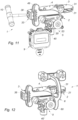
- the clamping screw 38 has a threaded rod engaged in the threaded portion of the clamping orifice 37, and it has a head provided with an indentation suitable for cooperating with a clamping screwdriver 10 (visible on the figure 11 ); this head of the clamping screw 38 coming into abutment against an internal shoulder provided in the smooth portion of the clamping orifice 37.
- the clamping screw 38 forms a clamping element cooperating with the jaw 33 to move the jaws 34, 35 between a clamped position (where the jaws 34, 35 are brought together and the slot 330 is reduced) and a loosened position (where the jaws 34, 35 are moved apart and the slot 330 is enlarged compared to the clamped position).
- screwing in the clamping screw 38 moves the jaws 34, 35 towards the clamped position and unscrewing the clamping screw 38 moves the jaws 34, 35 towards the loosened position.
- the outer jaw 35 has a notch 351 facing the inner jaw 34, and the inner jaw 34 has a shoulder 341 facing the outer jaw 35; the notch 351 and the shoulder 341 thus being opposite each other.
- this reference mark 36 is also provided a reference mark 36 made on the outer jaw 35, this reference mark 36 forming a second marking element to measure a pivot angle value of the femoral plate 31 relative to the tibial plate 21.
- the femoral element 3 also has a central stud 39, projecting from an upper face of the femoral plateau 31 and located in a median plane of the femoral plateau 31 including the antero-posterior axis AP; this upper face being opposite a lower face which faces the tibial plateau 21.
- the pivot shaft 30 extends this central stud 39.
- the movable element 4 is formed from a single piece and mainly comprises the guide 40 extending along the longitudinal axis AL and surmounted by a body 41 extending transversely on either side of the longitudinal axis AL.
- the guide 40 is in the form of a rod provided with a rack 42 formed of a series of teeth regularly distributed along the longitudinal axis AL on a slice of the rod, where this guide 40 is mounted sliding at the inside the guide orifice 22 provided in the base 20 of the static tibial element 2.
- the rack 42 thus has a pitch which corresponds to the spacing between two successive teeth.
- the guide 40 also has a key (not visible) intended to engage in the groove 220 of the guide orifice 22 to prevent the rotation of the guide 40 inside the guide orifice 22.
- the adjustment system 5 comprises a pinion 50 which is pivotally mounted on the base 20 of the static tibial element 2 in a direction parallel to the antero-posterior axis AP, and which is more precisely pivotally mounted inside the adjustment hole 27.
- the pinion 50 is integral in rotation with an adjustment screw 53 provided with a specific imprint to cooperate with the aforementioned tightening screwdriver 10 (visible on the figure 11 ).
- the screwing of the adjustment screw 53 moves the pinion 50 in rotation in a first direction of rotation S1, which drives the guide 40 in translation upwards to move the femoral plate 31 in the direction of a gap vis- opposite the tibial plateau 21.
- the guide 40 also has a scale of graduations 48 distributed along the longitudinal axis AL; this scale of graduations 48 forming a first measuring element for measuring a distance value between the femoral plateau 31 and the tibial plateau 21.
- this scale of graduations 48 is visible through the window 23 provided on the front face 201 of the base 20, and the marker 24 provided on the side of the window 23 in visual correspondence with the graduation scale 48, so as to measure a distance value along the longitudinal axis AL between the femoral plate 31 and the tibial plateau 21.
- the graduation scale 48 is graduated every 1 millimeter.
- the adjustment system 5 comprises a reversible locking mechanism coupled between the base 20 of the static tibial element 2 and the pinion 50 to reversibly lock the rotation of the pinion 50 and consequently the mobility of the guide 40 relative to the base, in order to fix the distance between the femoral plate 31 and the tibial plate 21.
- the reversible locking mechanism comprises a trigger 54 pivotally mounted on the base 20 in a direction parallel to the antero-posterior axis AP, and more precisely the trigger 54 is pivotally mounted on the first finger 28 provided in projection on the front face 201 of the base 20.
- the arm 55 of the trigger 54 is also provided with a second end, opposite the first end, on which is provided a support surface 57 allowing the surgeon to press on it to make the arm 55 pivot in the direction of uncoupling of the pawl 56 with the one-way notches of the first pinion portion 51 of the pinion 50, which unlocks the trigger 54.
- this pressure support 57 the trigger 54 is uncoupled from the pinion 50 ( unlocked position) which is thus authorized to rotate in both directions of rotation S1, S2.
- This trigger 54 is also provided with an elastic return member 58 urging the arm 55 towards the locking position, in other words towards a locking position (or coupling) of the pawl 56 in the unidirectional notches of the first pinion portion 51 of the pinion 50.
- This elastic return member 58 is in the form of a lever integral with the pawl and having a free end which rests on the second finger 29.
- the arch 45 is provided with a scale of graduations 46 distributed around the antero-posterior axis AP, this scale of graduations 46 forming a first locating element for measuring a pivot angle value of the femoral plate 31 relative to the tibial plateau 21.
- the reference mark 36 provided on the outer jaw 35 of the femoral element 3 comes into visual correspondence with the graduation scale 46, so as to measure a pivot angle value of the femoral plateau 31 relative to the tibial plateau 21.
- the graduation scale 46 is graduated every 1 degree, between - 10 degrees and + 10 degrees, the zero angle or 0 degree corresponding to a parallelism between the femoral plateau 31 and the tibial plateau 21.
- the arch 45 has an arcuate outer edge, according to a curvature substantially centered on the antero-posterior axis AP, and in which is provided a rail 49 along which is arranged the scale of graduations 46.
- the surgical instrument 1 further comprises a reversible locking system coupled between the transverse arm 43 of the mobile element 4 and the femoral arm 32 of the femoral element 3 to reversibly immobilize the pivoting of the femoral element 3 with respect to the movable element 4 in order to fix the pivoting angle of the femoral plate 31 relative to the tibial plate 21 at different pivoting angle values.
- the rail 49 is free to move between the two jaws 34, 35 and it is therefore free to pivot around the antero-posterior axis AP, so that the femoral element 3 is authorized to pivot by relative to the movable element 4.
- the surgeon can use the tightening screwdriver 10 as a lever arm, once engaged with the tightening screw 38, in order to cause the femoral element 3 to pivot relative to the movable element 4 when the jaws 34, 35 are in the released position, then when he considers that the pivot angle suits him, it is then sufficient to screw the clamping screw 38 and thus to tighten the jaw 33 to be in the clamped position.
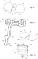
- This surgical instrument 1 can be used with a force sensor 8 adapted to be placed in a removable manner on the upper face of the femoral plate 31, in order to detect one or more forces exerted by the condyles of the femur on the femoral plate 31.
- this force sensor 8 comprises a medial sensor 81 designed to detect a force exerted by the medial condyle of the femur on the femoral plateau 31, and a lateral sensor 82 designed to detect a force exerted by the lateral condyle of the femur on the femoral plateau 31.
- the situation can be reversed depending on whether it is the right knee or the left knee.
- This force sensor 8 is provided with two lugs 83 facing each other configured to engage in the notches 390 of the central stud 39 of the femoral element 3, in order to mate with the lower polarizers to allow positioning unequivocally this force sensor 8.
- This force sensor 8 is connected to a measuring device 9, by a wireless channel or by a wired channel as in the example illustrated, this wired path in the form of a connection layer 84.
- the pivot arm 44 may have, above the pivot hole 47, a platform 440 serving as a guide or support in order to help the positioning of the connection cable 84.
- this measuring device 9 comprises a casing 90 inside which is provided an electric battery and a control unit, not visible and comprising for example an electronic chip, a processor, a controller and/or an electronic card; this control unit being provided to receive the measurements made by the force sensor 8.
- the box 90 has on its sides, on the right and on the left, two annular holding barrels 91 capable of receiving the two pins 25 internally in order to be able to removably mount the measuring device 9 on the base 20 of the static tibial element 2.
- This measuring device 9 is also provided with a display 92 on the front panel, providing a display of the measurements made by the force sensor 9.
- An operating tab 93 is also provided for contacting the electric battery and an on-board contactor (not visible) to put the force sensor 8 into operation.
- This surgical instrument 1 can be used with a compensation wedge 7 adapted to be placed in a removable manner on the upper face of the femoral plate 31, and in particular on the force sensor 8 if the latter is present.
- this compensation wedge 7 comprises a medial compartment 71 provided for support of the medial distal condyle of the femur, and a lateral compartment 72 provided for support of the lateral distal condyle of the femur.
- the medial compartment 71 and the lateral compartment 72 are connected by a central bridge 74. The situation can be reversed depending on whether it is the right knee or the left knee.
- This compensation wedge 7 is provided with two lugs 73 facing each other configured to engage in the notches 390 of the central stud 39 of the femoral element 3, in order to mate with the upper polarizers (above of the lower polarizers) to allow this compensating wedge 7 to be positioned in an unambiguous manner.
- This surgical instrument 1 can also be used with a guide element 6 forming a positioner for nails which will then be used to fix one or more femoral cutting guides.
- this guide element 6 is formed from a single piece comprising a base 60 provided with two retaining pins 61 able to engage in the two retaining holes 26 provided on the base 20 of the static tibial element 2, in order to removably mount this guide element 6 on the base 20.
- This guide element 6 comprises an arm 62 extending the base 60 and ending with one end secured to a support 63 in which several guide orifices 64 are provided, on the right and on the left, to position or guide the holes in the femur ; such holes can then be used to fix the femoral cutting guide(s).
- the guide holes 64 thus form drill bushes corresponding to different insert thicknesses and go in pairs parallel to the support plane of the tibial plateau 21 on the resected end of the tibia.
- the rest of the description relates to the use of the surgical instrument 1 by a surgeon.
- the surgeon After making the tibial cut and the distal femoral cut, and after placing the leg in extension, the surgeon inserts the surgical instrument 1, the compensation wedge 7 and the force sensor 8 into the joint. in place.
- the rotation of the femoral plate 21 is optionally locked on a pivot angle value of 0 degrees using the locking screw 38 and the tightening screwdriver 10.
- the display 92 of the measuring device 9 indicates to the surgeon an objective assessment of ligament tension.
- the joint is then tensioned with the tightening screwdriver 10 inserted into the adjustment screw 53 coupled to the pinion 50 until a tension is obtained that the surgeon considers satisfactory.
- the value of the distance between the femoral plate 31 and the tibial plate 21 (or distraction value) is indicated by the mark 24 in visual correspondence with the scale of graduations 48, and this value corresponds to the thickness of the insert that will have to be used during the establishment of the definitive implants.
- the surgeon After placing the leg in flexion, the surgeon inserts the surgical instrument 1 and the force sensor 8 into the joint, and puts the patella back in place.
- the rotation of the femoral plate 21 is unlocked by means of the tightening screwdriver 10 engaged in the locking screw 38, so that the femoral plate 21 pivots freely around the antero-posterior axis AP.
- the display 92 of the measuring device 9 indicates an objective evaluation of the ligament tension.
- the joint is then tensioned with the tightening screwdriver 10 inserted into the adjustment screw 53 coupled to the pinion 50 until a tension is obtained that the surgeon considers satisfactory.
- the femoral plate 21 pivots freely around the antero-posterior axis AP, which tends to balance the forces.
- the surgeon can be satisfied with the balance obtained mechanically or adjust the balance by using the lever arm effect offered by the tightening screwdriver engaged in the locking screw 38, the adjustment thus obtained is fixed by screwing the locking screw 38 until locking the rotation of the femoral plate 31.
- the guide element 6 is then mounted on the base 20 of the static tibial element 2, and the surgeon uses the thickness of the insert obtained earlier to identify the guide holes 64 in which to make the drillings to then screw in two fixation pins of the femoral cutting guide.
- the surgical instrument 1, the force sensor 8 and the guide element 6 are then extracted from the joint, and the femoral cutting guide is placed on the two previously screwed pins.
- femoral cuts can be made and implants can be placed.
- ligament balancing is ultimately reproduced by the implants.
- this surgical instrument 100 differs mainly from the surgical instrument 1, in the form of the reversible locking mechanism configured to reversibly lock the mobility of the guide 40 relative to the base 20, in order to fix the spacing between the plate femoral 31 and the tibial plateau 21.
- the reversible locking mechanism comprises a trigger 54 movably mounted on the base 20 of the static tibial element 2 in order to cooperate with the pinion 50 to lock it in rotation.
- the reversible locking mechanism comprises two bolts 540 both mounted mobile on the base 20 of the static tibial element 2 in order to cooperate with the rack 42 (and not with the pinion 50) to lock directly and reversibly the mobility of this rack 42, and therefore of the guide 40, in translation.
- each bolt 540 is integral with an elastic return member 580 which is specific to it, and this elastic return member 580 is in the form of an elastic blade integral with the bolt 540 and which has a free part extending along the along the second portion 542, where this free part is able to bear against the rack 42 located opposite in order to exert a return force which tends to move the second portion 542 away from the rack 42 and therefore to bring the pawl closer 560 of rack 42.
- the surgeon must press the second portions 542 of the two bolts 540 arranged side by side, against the elastic return members 580.
- these bolts 540 are offset from each other along the longitudinal axis AL by a difference corresponding to half a pitch of the rack 42, so that when a bolt 540 is in the locking between two teeth of the rack 42 then the other bolt 540 is in the unlocking position by being in contact with a top of a tooth of the rack 42.
- the pinion 50 has only the second pinion portion 52 which meshes with the rack or series of teeth 42 of the guide 40, where this second pinion portion 52 is presented under the shape of a toothed wheel comprising bidirectional (or symmetrical) notches on the periphery.
- the first portion 51 described previously is useless in this surgical instrument 100, insofar as the bolts 540 engage directly with the rack 42.
Landscapes
- Health & Medical Sciences (AREA)
- Life Sciences & Earth Sciences (AREA)
- Orthopedic Medicine & Surgery (AREA)
- Surgery (AREA)
- Transplantation (AREA)
- General Health & Medical Sciences (AREA)
- Engineering & Computer Science (AREA)
- Heart & Thoracic Surgery (AREA)
- Veterinary Medicine (AREA)
- Animal Behavior & Ethology (AREA)
- Biomedical Technology (AREA)
- Public Health (AREA)
- Oral & Maxillofacial Surgery (AREA)
- Nuclear Medicine, Radiotherapy & Molecular Imaging (AREA)
- Physical Education & Sports Medicine (AREA)
- Cardiology (AREA)
- Vascular Medicine (AREA)
- Molecular Biology (AREA)
- Medical Informatics (AREA)
- Biophysics (AREA)
- Dentistry (AREA)
- Prostheses (AREA)
Claims (15)
- Chirurgisches Instrument (1; 100) für ein Ausbalancieren des Knies im Rahmen einer Vorbereitung für das chirurgische Einsetzen einer Knievollprothese, wobei das chirurgische Instrument (1) umfasst:- Ein statisches Tibiaelement (2), beinhaltend eine Basis (20), die fest mit einer Tibiaplatte (21) verbunden ist, das dazu vorgesehen ist, auf einem resektierten proximalen Ende der Tibia zum Aufliegen zu kommen;- ein Femurelement (3), beinhaltend eine Femurplatte (31), das dazu vorgesehen ist, auf den distalen oder hinteren Kondylen des Femurs oder auf einem resektierten distalen Ende des Femurs oder auf einem Ausgleichskeil (7) zum Aufliegen zu kommen;- ein bewegliches Element (4), beinhaltend eine Führung (40), die translationsbeweglich auf der Basis (20) des statischen Tibiaelements (2) gemäß einer Längsachse (AL) montiert ist, und wobei das Femurelement (3) schwenkend auf dem beweglichen Element (4) gemäß einer anteroposterioren Achse (AP) montiert ist, so dass die Femurplatte (31) sich um die anteroposteriore Achse (AP) in Bezug auf die Tibiaplatte (21), die statisch ist, schwenkt;- ein Einstellungssystem (5), das zwischen der Führung (40) des beweglichen Elements (4) und der Basis (20) des statischen Tibiaelements (2) gekoppelt ist, für eine Einstellung der Beweglichkeit der Führung (40) in Bezug auf die Basis (20), um für eine Ablenkungsfunktion zu sorgen, indem eine Einstellung des Abstands zwischen der Femurplatte (31) und der Tibiaplatte (21) ermöglicht wird;wobei das bewegliche Element (4) einen Querarm (43) umfasst, der fest mit der Führung (40) verbunden ist, und das Femurelement (3) einen Femurarm (32) umfasst, der fest mit der Femurplatte (31) verbunden ist;und wobei das chirurgische Instrument (1; 100) weiterhin ein reversibles Blockiersystem, das zwischen dem Querarm (43) des beweglichen Elements (4) und dem Femurarm (32) des Femurelements (3) gekoppelt ist, zum Immobilisieren des Schwenkens des Femurelements (3) in Bezug auf das bewegliche Element (4) auf reversible Weise umfasst, um den Schwenkwinkel der Femurplatte (31) in Bezug auf die Tibiaplatte (21) auf unterschiedliche Schwenkwinkelwerte festzulegen,wobei das chirurgische Instrument (1; 100) dadurch gekennzeichnet ist, dass das reversible Blockiersystem umfasst:- eine Klemme (33), die an einem freien Ende des Femurarms (32) vorgesehen ist und die zwei gegenüberliegende Backen (34, 35) umfasst, die zwischen einer geklemmten Position und einer gelösten Position beweglich sind;- eine Schiene (49), die an einem freien Ende des Querarms (43) des beweglichen Elements (4) vorgesehen ist und die im Inneren der Klemme (33) zwischen den zwei Backen (34, 35) in Eingriff genommen wird;- ein Klemmelement (38), das mit der Klemme (33) zusammenwirkt, zum Verstellen der Backen (34, 35) zwischen der geklemmten Position und der gelösten Position, wobei das Femurelement (3) in der geklemmten Position in seinem Schwenken in Bezug auf das bewegliche Element (4) immobilisiert ist und wobei in der gelösten Position zugelassen wird, dass das Femurelement (3) sich in Bezug auf das bewegliche Element (4) schwenkt;und dass das Klemmelement eine Klemmschraube (38) umfasst, die in eine Klemmöffnung (37) geschraubt ist, die durch die zwei Backen (34, 35) verläuft, so dass das Einschrauben der Klemmschraube (38) die Backen (34, 35) zu der geklemmten Position verstellt und das Ausschrauben der Klemmschraube (38) die Backen (34, 35) zu der gelösten Position verstellt;und dass die Klemmschraube (38) und die Klemmöffnung (37) sich gemäß einer Querachse (AT) erstrecken, die orthogonal zu der anteroposterioren Achse (AP) ist.
- Chirurgisches Instrument (1; 100) nach Anspruch 1, wobei der Querarm (43) des beweglichen Elements (4) in einem freien Ende endet, das mit einem ersten Kennzeichnungselement (46) versehen ist, und der Femurarm (32) des Femurelements (3) in einem freien Ende endet, das mit einem zweiten Kennzeichnungselement (36) versehen ist, wobei das erste Kennzeichnungselement (46) und das zweite Kennzeichnungselement (36) eine Skala mit Teilstrichen, die um die anteroposteriore Achse (AP) verteilt sind, und eine Referenzmarkierung, die optisch der Skala mit Teilstrichen entspricht, umfassen, um einen Schwenkwinkelwert der Femurplatte (31) in Bezug auf die Tibiaplatte (21) zu messen.
- Chirurgisches Instrument (1; 100) nach einem der Ansprüche 1 und 2, wobei die Klemme (33) von einem geschlitzten Schieber gebildet wird, in dem ein Schlitz (330) zwischen den zwei Backen (34, 35) vorgesehen ist.
- Chirurgisches Instrument (1; 100) nach einem der vorhergehenden Ansprüche, wobei die Führung (40) eine Zahnleiste (42) umfasst, die von einer Reihe Zähnen gebildet wird, und das Einstellungssystem (5) ein Zahnrad (50) umfasst, das schwenkend auf der Basis (20) des statischen Tibiaelements (2) montiert ist und das mit der Zahnleiste (42) verzahnt ist.
- Chirurgisches Instrument (1) nach Anspruch 4, wobei das Einstellungssystem (5) einen reversiblen Verriegelungsmechanismus, der zwischen der Basis (20) des statischen Tibiaelements (2) und dem Zahnrad (50) gekoppelt ist, zum Verriegeln der Drehung des Zahnrads (50) und infolgedessen der Beweglichkeit der Führung (40) in Bezug auf die Basis (20) auf reversible Weise umfasst, um den Abstand zwischen der Femurplatte (31) und der Tibiaplatte (21) festzulegen.
- Chirurgisches Instrument (1) nach Anspruch 5, wobei der reversible Verriegelungsmechanismus einen Abzug (54) umfasst, der beweglich auf der Basis (20) des statischen Tibiaelements (2) zwischen einer Verriegelungsposition, in der der Abzug (54) mit dem Zahnrad (50) zusammenwirkt, um es in der Drehung zu verriegeln, und einer Entriegelungsposition, in der der Abzug (54) nicht mit dem Zahnrad (50) zusammenwirkt, das sich frei schwenken kann, montiert ist.
- Chirurgisches Instrument (100) nach Anspruch 4, wobei das Einstellungssystem (5) einen reversiblen Verriegelungsmechanismus, der zwischen der Basis (20) des statischen Tibiaelements (2) und der Zahnleiste (42) gekoppelt ist, zum Verriegeln der Beweglichkeit der Führung (40) in Bezug auf die Basis (20) direkt und auf reversible Weise umfasst, um den Abstand zwischen der Femurplatte (31) und der Tibiaplatte (21) festzulegen.
- Chirurgisches Instrument (100) nach Anspruch 7, wobei der reversible Verriegelungsmechanismus mindestens einen Riegel (540) umfasst, der schwenkend auf der Basis (20) zwischen einer Verriegelungsposition, in der der Riegel (540) im Eingriff zwischen zwei Zähnen der Zahnleiste (42) steht, um sie in der Drehung zu verriegeln, und einer Entriegelungsposition, in der der Riegel (540) nicht mit den Zähnen der Zahnleiste (42) zusammenwirkt, um zuzulassen, dass sie sich verschiebt, montiert ist.
- Chirurgisches Instrument (100) nach Anspruch 8, wobei der reversible Verriegelungsmechanismus zwei Riegel (540) umfasst, die schwenkend auf der Basis zwischen einer Verriegelungsposition und einer Entriegelungsposition montiert sind,
und wobei die Riegel (540) gemäß der Längsachse (AL) um einen Abstand, der der Hälfte eines Schritts der Zahnleiste (42) entspricht, voneinander versetzt sind, wobei der Schritt der Zahnleiste (42) dem Abstand zwischen zwei aufeinanderfolgenden Zähnen entspricht, so dass, wenn ein Riegel (540) in der Verriegelungsposition zwischen zwei Zähnen der Zahnleiste (42) ist, der andere Riegel (540) in der Entriegelungsposition ist, indem er im Kontakt mit einem Scheitelpunkt eines Zahns der Zahnleiste (42) steht. - Chirurgisches Instrument (1; 100) nach einem der Ansprüche 4 bis 9, wobei:- die Führung (40) mit einem ersten Messelement (48) versehen ist;- die Basis (20) des statischen Tibiaelements (2) ein Fenster (23) aufweist, durch das das erste Messelement (48) der Führung (40) sichtbar ist, und die Basis (20) weiterhin ein zweites Messelement (24) aufweist, das an der Seite des Fensters angeordnet ist;- das erste Messelement (48) und das zweite Messelement (24) eine Skala mit Teilstrichen, die entlang der Längsachse (AL) verteilt sind, und eine Referenzmarkierung, die optisch der Skala mit Teilstrichen entspricht, umfassen, um einen Wert eines Abstands zwischen der Femurplatte (31) und der Tibiaplatte (21) zu messen.
- Chirurgisches System, umfassend ein chirurgisches Instrument (1; 100) nach einem der Ansprüche 1 bis 10 und weiterhin umfassend einen Klemmschraubendreher (10), der dazu geeignet ist, mit der Klemmschraube (38) zusammenzuwirken, um deren Einschrauben/Ausschrauben sicherzustellen, und außerdem dazu geeignet ist, einen Hebelarm zu bilden, sobald er mit der Klemmschraube (38) eingerastet ist, um das Femurelement (3) in Bezug auf das bewegliche Element (4) schwenken zu lassen, wenn die Backen (34, 35) in der gelösten Position sind.
- Chirurgisches System, umfassend ein chirurgisches Instrument (1; 100) nach einem der Ansprüche 1 bis 10 und weiterhin umfassend einen Kraftsensor (8), der dazu eingerichtet ist, auf abnehmbare Weise auf einer oberen Fläche der Femurplatte (31), die entgegengesetzt zu einer unteren Fläche ist, die der Tibiaplatte (21) zugewandt ist, angeordnet zu werden, um eine oder mehrere Kräfte zu erkennen, die von den Kondylen des Femurs auf die Femurplatte (31) ausgeübt werden.
- Chirurgisches System nach Anspruch 12, weiterhin umfassend ein Messgerät (9), das drahtlos oder drahtgebunden mit dem Kraftsensor (8) verbunden ist und dazu vorgesehen ist, Messungen zu empfangen, die von dem Kraftsensor (8) durchgeführt werden, wobei das Messgerät (9) auf abnehmbare Weise auf der Basis (20) des statischen Tibiaelements (2) montiert ist.
- Chirurgisches System nach Anspruch 13, wobei das Messgerät (9) eine Anzeige (92) umfasst oder mit einer Fernanzeige verbunden ist, um die vom Kraftsensor (8) durchgeführten Messungen anzuzeigen.
- Chirurgisches System, umfassend ein chirurgisches Instrument (1; 100) nach einem der Ansprüche 1 bis 10 und weiterhin umfassend ein Führungselement (6), das auf abnehmbare Weise auf der Basis (20) des statischen Tibiaelements (2) montiert ist, wobei das Führungselement (6) mehrere Führungsöffnungen (64) für Bohrungen in das Femur umfasst.
Applications Claiming Priority (2)
| Application Number | Priority Date | Filing Date | Title |
|---|---|---|---|
| FR1854341A FR3081310B1 (fr) | 2018-05-24 | 2018-05-24 | Instrument chirurgical pour un equilibrage du genou |
| PCT/FR2019/051184 WO2019224488A1 (fr) | 2018-05-24 | 2019-05-23 | Instrument chirurgical pour un équilibrage du genou |
Publications (3)
| Publication Number | Publication Date |
|---|---|
| EP3801398A1 EP3801398A1 (de) | 2021-04-14 |
| EP3801398B1 true EP3801398B1 (de) | 2023-06-28 |
| EP3801398C0 EP3801398C0 (de) | 2023-06-28 |
Family
ID=63080112
Family Applications (1)
| Application Number | Title | Priority Date | Filing Date |
|---|---|---|---|
| EP19737811.0A Active EP3801398B1 (de) | 2018-05-24 | 2019-05-23 | Chirurgisches instrument für das knieausgleich |
Country Status (5)
| Country | Link |
|---|---|
| US (1) | US10874525B2 (de) |
| EP (1) | EP3801398B1 (de) |
| ES (1) | ES2957318T3 (de) |
| FR (1) | FR3081310B1 (de) |
| WO (1) | WO2019224488A1 (de) |
Families Citing this family (16)
| Publication number | Priority date | Publication date | Assignee | Title |
|---|---|---|---|---|
| US11000382B1 (en) | 2018-11-15 | 2021-05-11 | Little Engine, LLC | Apparatus and method for joint characterization and treatment |
| US10772617B2 (en) * | 2018-11-15 | 2020-09-15 | Little Engine, LLC | Knee flexion and extension gap tensioning and measuring apparatus |
| US12433656B2 (en) * | 2019-03-29 | 2025-10-07 | Depuy Ireland Unlimited Company | Methods, surgical instruments, and associated systems for performing a surgical procedure to balance a patient's knee |
| US12484891B2 (en) * | 2020-02-11 | 2025-12-02 | Smith & Nephew, Inc. | Joint tensioning device and methods of use thereof |
| CN111281480B (zh) * | 2020-03-30 | 2024-11-01 | 北京市春立正达医疗器械股份有限公司 | 膝关节置换股骨髁中线定位导向器 |
| JP7474986B2 (ja) | 2020-07-29 | 2024-04-26 | 慶應義塾 | 脛骨切除支援装置 |
| JP2024522198A (ja) * | 2021-06-11 | 2024-06-11 | オプティモーション インプランツ リミテッド ライアビリティ カンパニー | 関節形成バランスとギャップゲージ |
| CN113693674B (zh) * | 2021-08-30 | 2023-08-15 | 万春友 | 固定支架 |
| US11612421B1 (en) | 2021-09-20 | 2023-03-28 | Little Engine, LLC | Tensioner-balancer for knee joint |
| US11806853B2 (en) * | 2022-03-04 | 2023-11-07 | Urban Machine, Inc. | System and method for autonomously removing fasteners embedded in wood products |
| US11612503B1 (en) | 2022-06-07 | 2023-03-28 | Little Engine, LLC | Joint soft tissue evaluation method |
| US11839550B1 (en) | 2022-06-07 | 2023-12-12 | Little Engine, LLC | Machine learning based joint evaluation method |
| US11642118B1 (en) | 2022-06-07 | 2023-05-09 | Little Engine, LLC | Knee tensioner-balancer and method |
| US12491032B2 (en) | 2023-11-01 | 2025-12-09 | Dynamic Balancer Systems Llc | Knee arthroplasty method |
| US12303405B2 (en) | 2023-11-01 | 2025-05-20 | Dynamic Balancer Systems Llc | Knee arthroplasty method |
| WO2025213055A1 (en) * | 2024-04-05 | 2025-10-09 | Knimble Designs, Inc. | Methods and apparatuses for performing a knee arthroplasty |
Family Cites Families (12)
| Publication number | Priority date | Publication date | Assignee | Title |
|---|---|---|---|---|
| GB9611074D0 (en) * | 1996-05-28 | 1996-07-31 | Howmedica | Surgical apparatus |
| JP4095919B2 (ja) * | 2002-12-09 | 2008-06-04 | ジンマー株式会社 | 人工膝関節全置換手術用計測装置 |
| US20100249790A1 (en) * | 2009-03-26 | 2010-09-30 | Martin Roche | System and method for soft tissue tensioning in extension and flexion |
| US7615055B2 (en) * | 2005-03-31 | 2009-11-10 | Depuy Products, Inc. | Method and apparatus for use in balancing ligaments of a knee |
| US8506571B2 (en) * | 2008-10-23 | 2013-08-13 | Synvasive Technology, Inc. | Knee balancing for revision procedures |
| US8118815B2 (en) * | 2009-07-24 | 2012-02-21 | OrthAlign, Inc. | Systems and methods for joint replacement |
| FR2948274B1 (fr) * | 2009-07-24 | 2011-09-16 | Tornier Sa | Instrumentation chirurgicale pour la preparation a la pose d'une prothese de genou |
| EP2734123B1 (de) * | 2011-07-19 | 2017-03-08 | Zimmer, Inc. | Instrument für kniearthroplastik |
| US9592133B2 (en) * | 2013-09-23 | 2017-03-14 | Zimmer, Inc. | Spacer block |
| WO2016071516A1 (en) * | 2014-11-07 | 2016-05-12 | Implantcast Gmbh | A method and apparatus for joint reconstruction |
| US10076344B2 (en) * | 2014-11-19 | 2018-09-18 | Zimmer, Inc. | Gap referencing femoral sizer |
| JP7344122B2 (ja) * | 2017-03-14 | 2023-09-13 | オースアライン・インコーポレイテッド | 軟部組織の測定およびバランシングを行うシステムおよび方法 |
-
2018
- 2018-05-24 FR FR1854341A patent/FR3081310B1/fr not_active Expired - Fee Related
- 2018-06-01 US US15/996,395 patent/US10874525B2/en not_active Expired - Fee Related
-
2019
- 2019-05-23 ES ES19737811T patent/ES2957318T3/es active Active
- 2019-05-23 EP EP19737811.0A patent/EP3801398B1/de active Active
- 2019-05-23 WO PCT/FR2019/051184 patent/WO2019224488A1/fr not_active Ceased
Also Published As
| Publication number | Publication date |
|---|---|
| WO2019224488A1 (fr) | 2019-11-28 |
| EP3801398A1 (de) | 2021-04-14 |
| US20190358056A1 (en) | 2019-11-28 |
| FR3081310A1 (fr) | 2019-11-29 |
| ES2957318T3 (es) | 2024-01-17 |
| FR3081310B1 (fr) | 2023-06-30 |
| EP3801398C0 (de) | 2023-06-28 |
| US10874525B2 (en) | 2020-12-29 |
Similar Documents
| Publication | Publication Date | Title |
|---|---|---|
| WO2019224488A1 (fr) | Instrument chirurgical pour un équilibrage du genou | |
| EP1643916B1 (de) | Vorrichtung zur unterstützung bei der implantation einer knietotalprothese | |
| EP1599140B1 (de) | Kniegelenkdistraktor | |
| US9498199B2 (en) | Distractor instrument | |
| FR2737967A1 (fr) | Appareil de correction d'espaces pour prothese du genou | |
| EP1732448B1 (de) | Hilfsanordnung zur implantation von knieprothesen | |
| EP2277460A1 (de) | Chirurgische Instrumentierung zur Vorbereitung des Einsetzens einer Knieprothese | |
| EP0914806B1 (de) | Gerät zur Durchtrennung des Femurs zum Einsetzen einer Kniegelenkprothese | |
| EP1651152A2 (de) | Vorrichtung für die dynamische spannung eines natürlichen oder prothetischen kniegelenks | |
| EP0236397A1 (de) | Verfahren zum einsetzen einer knieprothese und geräte dafür | |
| FR2752519A1 (fr) | Guides de coupe tibiale et femorale pour installation d'une prothese totale de genou | |
| FR2590159A1 (fr) | Appareillage pour la mise en place de protheses du genou notamment mono-compartimentaires internes et/ou externes, trochleo-condyliennes internes ou externes | |
| FR2635675A1 (fr) | Instrumentation ancillaire pour l'implantation d'une prothese totale du genou et secondairement pour osteotomies de correction axiale | |
| EP2330984A1 (de) | Zubehörset zur implantation einer knieprothese | |
| WO2016012731A1 (fr) | Dispositif chirurgical d'aide a la pose d'un implant orthopedique entre deux os d'une articulation d'un patient | |
| WO2008040790A1 (fr) | Dispositif de detection et de suivi d'une lesion du ligament croise anterieur du genou | |
| EP1304093B1 (de) | Hilfsinstrument zur Vorbereitung des Einsetzens einer Knieprothese | |
| EP0959780B1 (de) | Hilfsinstrument zur vorbereitung des einsetzens einer knieprothese | |
| FR3071147A1 (fr) | Dispositif d'aide a la pose d'une prothese de genou, outil distracteur et equilibreur du systeme ligamentaire du genou | |
| FR2867056A1 (fr) | Dispositif de coupes liees entre le tibia et le femur pour la mise en place d'une prothese | |
| FR3011171A1 (fr) | Ancillaire de mise en tension des ligaments lateraux interne et externe d’une articulation de genou | |
| FR2684870A1 (fr) | Procede de determination du point d'entree d'une tige intramedullaire femorale et dispositif de visualisation du point d'entree. | |
| EP0288402B1 (de) | Zweiteilige Kniegelenkprothese | |
| FR2732581A1 (fr) | Appareil destine a la realisation d'une coupe osseuse chirurgicale du genou et prothese unicompartimentale du genou correspondante | |
| FR2732210A1 (fr) | Appareil pour la preparation d'une rotule en vue de la mise en place d'un implant patellaire |
Legal Events
| Date | Code | Title | Description |
|---|---|---|---|
| STAA | Information on the status of an ep patent application or granted ep patent |
Free format text: STATUS: UNKNOWN |
|
| STAA | Information on the status of an ep patent application or granted ep patent |
Free format text: STATUS: THE INTERNATIONAL PUBLICATION HAS BEEN MADE |
|
| PUAI | Public reference made under article 153(3) epc to a published international application that has entered the european phase |
Free format text: ORIGINAL CODE: 0009012 |
|
| STAA | Information on the status of an ep patent application or granted ep patent |
Free format text: STATUS: REQUEST FOR EXAMINATION WAS MADE |
|
| 17P | Request for examination filed |
Effective date: 20201214 |
|
| AK | Designated contracting states |
Kind code of ref document: A1 Designated state(s): AL AT BE BG CH CY CZ DE DK EE ES FI FR GB GR HR HU IE IS IT LI LT LU LV MC MK MT NL NO PL PT RO RS SE SI SK SM TR |
|
| AX | Request for extension of the european patent |
Extension state: BA ME |
|
| DAV | Request for validation of the european patent (deleted) | ||
| DAX | Request for extension of the european patent (deleted) | ||
| GRAP | Despatch of communication of intention to grant a patent |
Free format text: ORIGINAL CODE: EPIDOSNIGR1 |
|
| STAA | Information on the status of an ep patent application or granted ep patent |
Free format text: STATUS: GRANT OF PATENT IS INTENDED |
|
| INTG | Intention to grant announced |
Effective date: 20220812 |
|
| RIN1 | Information on inventor provided before grant (corrected) |
Inventor name: GOUBET, NICOLAS Inventor name: THIBAUT, SYLVAIN Inventor name: LERAT, BERNARD |
|
| GRAJ | Information related to disapproval of communication of intention to grant by the applicant or resumption of examination proceedings by the epo deleted |
Free format text: ORIGINAL CODE: EPIDOSDIGR1 |
|
| STAA | Information on the status of an ep patent application or granted ep patent |
Free format text: STATUS: REQUEST FOR EXAMINATION WAS MADE |
|
| GRAP | Despatch of communication of intention to grant a patent |
Free format text: ORIGINAL CODE: EPIDOSNIGR1 |
|
| STAA | Information on the status of an ep patent application or granted ep patent |
Free format text: STATUS: GRANT OF PATENT IS INTENDED |
|
| INTC | Intention to grant announced (deleted) | ||
| INTG | Intention to grant announced |
Effective date: 20230118 |
|
| GRAS | Grant fee paid |
Free format text: ORIGINAL CODE: EPIDOSNIGR3 |
|
| GRAA | (expected) grant |
Free format text: ORIGINAL CODE: 0009210 |
|
| STAA | Information on the status of an ep patent application or granted ep patent |
Free format text: STATUS: THE PATENT HAS BEEN GRANTED |
|
| AK | Designated contracting states |
Kind code of ref document: B1 Designated state(s): AL AT BE BG CH CY CZ DE DK EE ES FI FR GB GR HR HU IE IS IT LI LT LU LV MC MK MT NL NO PL PT RO RS SE SI SK SM TR |
|
| REG | Reference to a national code |
Ref country code: CH Ref legal event code: EP |
|
| REG | Reference to a national code |
Ref country code: AT Ref legal event code: REF Ref document number: 1582060 Country of ref document: AT Kind code of ref document: T Effective date: 20230715 |
|
| REG | Reference to a national code |
Ref country code: IE Ref legal event code: FG4D Free format text: LANGUAGE OF EP DOCUMENT: FRENCH |
|
| REG | Reference to a national code |
Ref country code: DE Ref legal event code: R096 Ref document number: 602019031738 Country of ref document: DE |
|
| U01 | Request for unitary effect filed |
Effective date: 20230712 |
|
| U07 | Unitary effect registered |
Designated state(s): AT BE BG DE DK EE FI FR IT LT LU LV MT NL PT SE SI Effective date: 20230721 |
|
| REG | Reference to a national code |
Ref country code: LT Ref legal event code: MG9D |
|
| PG25 | Lapsed in a contracting state [announced via postgrant information from national office to epo] |
Ref country code: NO Free format text: LAPSE BECAUSE OF FAILURE TO SUBMIT A TRANSLATION OF THE DESCRIPTION OR TO PAY THE FEE WITHIN THE PRESCRIBED TIME-LIMIT Effective date: 20230928 |
|
| PG25 | Lapsed in a contracting state [announced via postgrant information from national office to epo] |
Ref country code: RS Free format text: LAPSE BECAUSE OF FAILURE TO SUBMIT A TRANSLATION OF THE DESCRIPTION OR TO PAY THE FEE WITHIN THE PRESCRIBED TIME-LIMIT Effective date: 20230628 Ref country code: HR Free format text: LAPSE BECAUSE OF FAILURE TO SUBMIT A TRANSLATION OF THE DESCRIPTION OR TO PAY THE FEE WITHIN THE PRESCRIBED TIME-LIMIT Effective date: 20230628 Ref country code: GR Free format text: LAPSE BECAUSE OF FAILURE TO SUBMIT A TRANSLATION OF THE DESCRIPTION OR TO PAY THE FEE WITHIN THE PRESCRIBED TIME-LIMIT Effective date: 20230929 |
|
| PG25 | Lapsed in a contracting state [announced via postgrant information from national office to epo] |
Ref country code: SK Free format text: LAPSE BECAUSE OF FAILURE TO SUBMIT A TRANSLATION OF THE DESCRIPTION OR TO PAY THE FEE WITHIN THE PRESCRIBED TIME-LIMIT Effective date: 20230628 |
|
| REG | Reference to a national code |
Ref country code: ES Ref legal event code: FG2A Ref document number: 2957318 Country of ref document: ES Kind code of ref document: T3 Effective date: 20240117 |
|
| PG25 | Lapsed in a contracting state [announced via postgrant information from national office to epo] |
Ref country code: IS Free format text: LAPSE BECAUSE OF FAILURE TO SUBMIT A TRANSLATION OF THE DESCRIPTION OR TO PAY THE FEE WITHIN THE PRESCRIBED TIME-LIMIT Effective date: 20231028 |
|
| PG25 | Lapsed in a contracting state [announced via postgrant information from national office to epo] |
Ref country code: SM Free format text: LAPSE BECAUSE OF FAILURE TO SUBMIT A TRANSLATION OF THE DESCRIPTION OR TO PAY THE FEE WITHIN THE PRESCRIBED TIME-LIMIT Effective date: 20230628 Ref country code: SK Free format text: LAPSE BECAUSE OF FAILURE TO SUBMIT A TRANSLATION OF THE DESCRIPTION OR TO PAY THE FEE WITHIN THE PRESCRIBED TIME-LIMIT Effective date: 20230628 Ref country code: RO Free format text: LAPSE BECAUSE OF FAILURE TO SUBMIT A TRANSLATION OF THE DESCRIPTION OR TO PAY THE FEE WITHIN THE PRESCRIBED TIME-LIMIT Effective date: 20230628 Ref country code: IS Free format text: LAPSE BECAUSE OF FAILURE TO SUBMIT A TRANSLATION OF THE DESCRIPTION OR TO PAY THE FEE WITHIN THE PRESCRIBED TIME-LIMIT Effective date: 20231028 Ref country code: CZ Free format text: LAPSE BECAUSE OF FAILURE TO SUBMIT A TRANSLATION OF THE DESCRIPTION OR TO PAY THE FEE WITHIN THE PRESCRIBED TIME-LIMIT Effective date: 20230628 |
|
| PG25 | Lapsed in a contracting state [announced via postgrant information from national office to epo] |
Ref country code: PL Free format text: LAPSE BECAUSE OF FAILURE TO SUBMIT A TRANSLATION OF THE DESCRIPTION OR TO PAY THE FEE WITHIN THE PRESCRIBED TIME-LIMIT Effective date: 20230628 |
|
| REG | Reference to a national code |
Ref country code: DE Ref legal event code: R097 Ref document number: 602019031738 Country of ref document: DE |
|
| PLBE | No opposition filed within time limit |
Free format text: ORIGINAL CODE: 0009261 |
|
| STAA | Information on the status of an ep patent application or granted ep patent |
Free format text: STATUS: NO OPPOSITION FILED WITHIN TIME LIMIT |
|
| 26N | No opposition filed |
Effective date: 20240402 |
|
| U20 | Renewal fee for the european patent with unitary effect paid |
Year of fee payment: 6 Effective date: 20240430 |
|
| REG | Reference to a national code |
Ref country code: CH Ref legal event code: PL |
|
| PG25 | Lapsed in a contracting state [announced via postgrant information from national office to epo] |
Ref country code: MC Free format text: LAPSE BECAUSE OF FAILURE TO SUBMIT A TRANSLATION OF THE DESCRIPTION OR TO PAY THE FEE WITHIN THE PRESCRIBED TIME-LIMIT Effective date: 20230628 |
|
| PG25 | Lapsed in a contracting state [announced via postgrant information from national office to epo] |
Ref country code: MC Free format text: LAPSE BECAUSE OF FAILURE TO SUBMIT A TRANSLATION OF THE DESCRIPTION OR TO PAY THE FEE WITHIN THE PRESCRIBED TIME-LIMIT Effective date: 20230628 Ref country code: CH Free format text: LAPSE BECAUSE OF NON-PAYMENT OF DUE FEES Effective date: 20240531 |
|
| PG25 | Lapsed in a contracting state [announced via postgrant information from national office to epo] |
Ref country code: IE Free format text: LAPSE BECAUSE OF NON-PAYMENT OF DUE FEES Effective date: 20240523 |
|
| U20 | Renewal fee for the european patent with unitary effect paid |
Year of fee payment: 7 Effective date: 20250418 |
|
| PGFP | Annual fee paid to national office [announced via postgrant information from national office to epo] |
Ref country code: GB Payment date: 20250418 Year of fee payment: 7 |
|
| PG25 | Lapsed in a contracting state [announced via postgrant information from national office to epo] |
Ref country code: CY Free format text: LAPSE BECAUSE OF FAILURE TO SUBMIT A TRANSLATION OF THE DESCRIPTION OR TO PAY THE FEE WITHIN THE PRESCRIBED TIME-LIMIT; INVALID AB INITIO Effective date: 20190523 |
|
| PG25 | Lapsed in a contracting state [announced via postgrant information from national office to epo] |
Ref country code: HU Free format text: LAPSE BECAUSE OF FAILURE TO SUBMIT A TRANSLATION OF THE DESCRIPTION OR TO PAY THE FEE WITHIN THE PRESCRIBED TIME-LIMIT; INVALID AB INITIO Effective date: 20190523 |
|
| PGFP | Annual fee paid to national office [announced via postgrant information from national office to epo] |
Ref country code: ES Payment date: 20250812 Year of fee payment: 7 |