EP3801231B1 - Measuring device for measuring physiological data of a mammal - Google Patents
Measuring device for measuring physiological data of a mammal Download PDFInfo
- Publication number
- EP3801231B1 EP3801231B1 EP19743017.6A EP19743017A EP3801231B1 EP 3801231 B1 EP3801231 B1 EP 3801231B1 EP 19743017 A EP19743017 A EP 19743017A EP 3801231 B1 EP3801231 B1 EP 3801231B1
- Authority
- EP
- European Patent Office
- Prior art keywords
- module
- measuring device
- pin
- opening
- tool
- Prior art date
- Legal status (The legal status is an assumption and is not a legal conclusion. Google has not performed a legal analysis and makes no representation as to the accuracy of the status listed.)
- Active
Links
- 241000124008 Mammalia Species 0.000 title claims description 10
- 241001465754 Metazoa Species 0.000 claims description 19
- 230000005855 radiation Effects 0.000 claims description 14
- 230000003213 activating effect Effects 0.000 claims description 10
- 230000004913 activation Effects 0.000 claims description 8
- 238000013519 translation Methods 0.000 claims description 7
- 239000011796 hollow space material Substances 0.000 claims description 6
- 230000005672 electromagnetic field Effects 0.000 claims description 5
- 230000000295 complement effect Effects 0.000 claims description 4
- 230000005670 electromagnetic radiation Effects 0.000 claims description 2
- 239000008280 blood Substances 0.000 description 4
- 210000004369 blood Anatomy 0.000 description 4
- 241000217377 Amblema plicata Species 0.000 description 3
- 239000000470 constituent Substances 0.000 description 2
- 230000000694 effects Effects 0.000 description 2
- 238000005265 energy consumption Methods 0.000 description 2
- 238000000034 method Methods 0.000 description 2
- 230000000717 retained effect Effects 0.000 description 2
- 210000003462 vein Anatomy 0.000 description 2
- 238000010521 absorption reaction Methods 0.000 description 1
- 230000036772 blood pressure Effects 0.000 description 1
- 230000002596 correlated effect Effects 0.000 description 1
- 230000000875 corresponding effect Effects 0.000 description 1
- 238000013461 design Methods 0.000 description 1
- 239000000463 material Substances 0.000 description 1
- 238000005259 measurement Methods 0.000 description 1
- 238000012545 processing Methods 0.000 description 1
- 238000001228 spectrum Methods 0.000 description 1
Images


Classifications
-
- A—HUMAN NECESSITIES
- A61—MEDICAL OR VETERINARY SCIENCE; HYGIENE
- A61B—DIAGNOSIS; SURGERY; IDENTIFICATION
- A61B5/00—Measuring for diagnostic purposes; Identification of persons
- A61B5/02—Detecting, measuring or recording pulse, heart rate, blood pressure or blood flow; Combined pulse/heart-rate/blood pressure determination; Evaluating a cardiovascular condition not otherwise provided for, e.g. using combinations of techniques provided for in this group with electrocardiography or electroauscultation; Heart catheters for measuring blood pressure
- A61B5/024—Detecting, measuring or recording pulse rate or heart rate
- A61B5/02416—Detecting, measuring or recording pulse rate or heart rate using photoplethysmograph signals, e.g. generated by infrared radiation
-
- A—HUMAN NECESSITIES
- A61—MEDICAL OR VETERINARY SCIENCE; HYGIENE
- A61B—DIAGNOSIS; SURGERY; IDENTIFICATION
- A61B5/00—Measuring for diagnostic purposes; Identification of persons
- A61B5/68—Arrangements of detecting, measuring or recording means, e.g. sensors, in relation to patient
- A61B5/6801—Arrangements of detecting, measuring or recording means, e.g. sensors, in relation to patient specially adapted to be attached to or worn on the body surface
-
- A—HUMAN NECESSITIES
- A61—MEDICAL OR VETERINARY SCIENCE; HYGIENE
- A61B—DIAGNOSIS; SURGERY; IDENTIFICATION
- A61B2503/00—Evaluating a particular growth phase or type of persons or animals
- A61B2503/40—Animals
-
- A—HUMAN NECESSITIES
- A61—MEDICAL OR VETERINARY SCIENCE; HYGIENE
- A61B—DIAGNOSIS; SURGERY; IDENTIFICATION
- A61B5/00—Measuring for diagnostic purposes; Identification of persons
- A61B5/68—Arrangements of detecting, measuring or recording means, e.g. sensors, in relation to patient
- A61B5/6801—Arrangements of detecting, measuring or recording means, e.g. sensors, in relation to patient specially adapted to be attached to or worn on the body surface
- A61B5/6813—Specially adapted to be attached to a specific body part
- A61B5/6814—Head
- A61B5/6815—Ear
-
- A—HUMAN NECESSITIES
- A61—MEDICAL OR VETERINARY SCIENCE; HYGIENE
- A61B—DIAGNOSIS; SURGERY; IDENTIFICATION
- A61B5/00—Measuring for diagnostic purposes; Identification of persons
- A61B5/68—Arrangements of detecting, measuring or recording means, e.g. sensors, in relation to patient
- A61B5/6801—Arrangements of detecting, measuring or recording means, e.g. sensors, in relation to patient specially adapted to be attached to or worn on the body surface
- A61B5/683—Means for maintaining contact with the body
- A61B5/6838—Clamps or clips
Definitions
- the invention relates to a measuring device for measuring physiological data of an animal such as a mammal for determining at least one condition parameter of the animal, comprising a first and second module (12, 14) which are configured to be worn, in use, by the animal, wherein the first and second module are furthermore configured for them, from a condition of being mechanically separated from each other, to be mechanically connected with each other whereby in the connected condition, in use, between the first and second module is a skin part of the animal, wherein one of the modules comprises a source (122) for emitting electromagnetic radiation such as light (L) and wherein another of the modules comprises a sensor system (142) for measuring a parameter such as intensity of a fraction (Lm) of the emitted radiation (L) received via that skin part and for generating a measuring signal (S L ) which is indicative of the measured parameter.
- a measuring device for measuring physiological data of an animal such as a mammal for determining at least one condition parameter of the animal, comprising a first and second module (12, 14)
- a device of this type is known from NL2015582 or US 2017/100045 A1 .
- a problem with such a device is that, in use, the source of one of the modules is not always optimally positioned with respect to the sensor system of the other module.
- the first and second module are attached to each other by means of a pin/hole connection whereby, after the first and second modules have been connected with each other, the first and second module can be rotated relative to each other around an axial axis of the pin.
- first and second module are attached to each other such that the source is situated approximately opposite the sensor system, it can still happen that, in use, the first and second module rotate relative to each other, for instance in that someone inadvertently touches either of the parts, or in that the first and second module in the process of being attached to each other are still rotated relative to each other unnoticed.
- the measuring device is characterized in that the measuring device is configured such that, in use, the first and second module can possibly have been connected or be connected (stably) with each other only when they have at least one mutual orientation that falls within a predetermined range of mutual orientations according to independent claim 1.
- first and second module Due to there being at least one mutual orientation where the first and second module can be connected with each other, it is only necessary, during connecting, to choose the right orientation where the first and second module can be connected with each other whereby in connected condition the sensor system and the source are situated opposite each other. Once the first and second module have been connected with each other in the correct manner, the position of the sensor system with respect to the source is maintained, remaining at least substantially unchanged.
- first and second module can possibly have been connected or be connected (stably) with each other only when they have one mutual orientation that falls within a predetermined range of mutual orientations according to claim 1.
- the limited turning involves a maximum angle A, where A is less than 15 degrees, preferably less than 10 degrees and more preferably less than 5 degrees.
- the measuring device is configured such that if the first and second module, in use, have been attached to each other, the first and second module can move relative to each other in a possible limited translation along an axis which is at least substantially perpendicular to a plane which, in use, extends parallel to sides of the first and second module that face each other. It is thus ensured that also with varying thicknesses of the skin part, the first and second module can be comfortably attached to the animal.
- the second module is provided with a lead-through opening and the first module is provided with a projecting pin, while, in use, the pin extends through the opening.
- an inner surface of the opening and an outer surface of the pin have a shape such that when an axial axis of the pin and an axial axis of the opening coincide, the pin can have been or be inserted into the opening only within at least one limited continuous range of rotation angles around its axial axis and with respect to the opening.
- the outer surface is provided with at least one groove which extends in a length direction of the pin while the inner surface is provided with at least one ridge which, in use, extends in the groove and/or that the inner surface is provided with at least one groove which extends in a length direction of the opening while the outer surface is provided with at least one ridge which extends in the length direction of the pin and which, in use, extends in the groove.
- the sensor system and the source are situated at least substantially opposite each other, such that radiation from the source is directed to the sensor system (142).
- the first and second module can be connected with each other only according to one possibility, so that, also during the actual connecting, that is, during the fitting to the animal, no mistakes can be made and the sensor system and source are always situated at least substantially opposite each other when the first and second module have been connected with each other.
- Approximately right positioning with respect to each other can be a consequence of tolerances to which the first and second module can be manufactured, but can also be a deliberate result of the design of the measuring device. In the latter case, it is thereby accomplished that, in use, upon attachment to the animal, it is only necessary that the first and second module, when being fitted to the animal, are positioned with respect to each other approximately in the right manner, which does not require absolute infinite precision.
- the measuring device is intended, with a relatively long useful life, to make measuring physiological data, such as the heartbeat of the mammal, possible.
- the measuring device provides in particular the possibility of measuring physiological data of a mammal for determining at least one condition parameter of the mammal.
- the measuring device accordingly comprises a measuring device to be worn by the mammal, having a first module and second module to be disposed mutually on opposite sides opposite a skin part of the mammal.
- the first module comprises the source for generating the radiation.
- the second module comprises the sensor unit for measuring an intensity of a fraction of the radiation received via that skin part and delivering a measuring signal which is indicative of the measured value of the radiation.
- the measuring device is preferably configured for pulsewise activating the source, while the measuring signal is indicative of the value of the intensity measured during the pulsewise activation.
- the measuring device may furthermore be provided with synchronization means for synchronously activating the source and the second module, while the synchronization means comprise an energy transmitting unit which is part of one of the first and the second module, and comprise a detector which is part of the other one of the first and the second module, while in an operating condition the energy transmitting unit pulsewise generates an electromagnetic field, and the detector receives this field and generates therefrom a supply voltage for use in that other module.
- the synchronization means comprise an energy transmitting unit which is part of one of the first and the second module, and comprise a detector which is part of the other one of the first and the second module, while in an operating condition the energy transmitting unit pulsewise generates an electromagnetic field, and the detector receives this field and generates therefrom a supply voltage for use in that other module.
- the at least one condition parameter to be determined is, for example, a heartbeat of the animal or a blood pressure of the animal.
- the condition parameter to be determined can be a blood value, i.e., an indication of a concentration of one or more constituents in the blood.
- a combination of condition parameters can be established with the measuring device and/or the measuring method.
- the radiation used for the measurement is preferably generated pulsewise, the intensity of the generated radiation can be raised without thereby also increasing the electrical energy consumption. Consequently, raising the intensity used does not need to be accompanied by a decrease of the useful life.
- the measuring device is configured for measuring physiological data of an animal, such as a mammal, for determining at least one condition parameter of the animal.
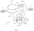
- the device comprises a first module 12 and a second module 14 which are configured to be worn, in use, by the animal.
- the first and second module are configured for them, from a condition of being mechanically separated from each other as shown in Figure 1 , to be connected with each other, whereby in connected condition, in use, between the first and second module is a skin part of the animal, as is also shown in Figure 8 .
- One of the two modules comprises a source 122 for emitting electromagnetic rays such as light. In this example, this involves the second module (see Fig. 3 ).
- Another one of the modules, in this example the first module 12 is provided with a sensor system 142 for measuring a parameter such as an intensity of a fraction (Lm) of the emitted radiation (L) received via the skin part, and for generating a measuring signal (S L ) which is indicative of the measured parameter.
- a sensor system 142 for measuring a parameter such as an intensity of a fraction (Lm) of the emitted radiation (L) received via the skin part, and for generating a measuring signal (S L ) which is indicative of the measured parameter.
- the measuring device 10 is configured such that, in use, the first and second module can possibly have been connected (stably) with each other only when they have at least one predetermined mutual orientation or when they have at least one mutual orientation that falls within a predetermined range of mutual orientations.
- Figure 1 there is shown the mutual orientation of the first and second module where they can be connected with each other when the first and second module are moved towards each other in the direction of the arrow P 1 .
- the second module is provided with a lead-through opening 16 and the first module 12 is provided with a projecting pin 18, this pin, in use, extending through the opening 16. This situation is shown in Figure 8 .
- An inner surface 20 of the opening 16 and an outer surface 22 of the pin 18 have a shape such that when an axial axis 26 of the pin 18 and an axial axis 28 of the opening 16 coincide, the pin can have been or be inserted into the opening only within at least one (in this example three) limited continuous range of rotation angles ⁇ around its axial axis and with respect to the opening.
- the inner surface 20 is provided with three grooves 30.1 - 30.3.
- the outer surface of the pin 18 is provided with three ridges 32.1 - 32.3 which extend in the length direction of the pin and which, in use, respectively extend in the grooves 30.1 - 30.3.
- the ridges 32.2 and 32.3 as well as the grooves 30.2 and 30.3 are omitted, so that the pin can only be slid into the opening in one rotational position of the angle ⁇ .
- a ridge has a thickness d as shown in Figure 1 somewhat smaller than a width D of a groove as shown in Figure 2 , this has as a consequence that when the pin has been slid into the opening, it can rotate relative to the opening in a limited continuous range of rotation angles around an axial axis.
- This has as an advantage that when the pin is being fitted into the opening the ridges and grooves do not need to be perfectly aligned with each other for the pin to be slid into the opening.
- the first and second module can possibly have been connected with each other only when they have a predetermined mutual orientation.
- the width of a groove is approximately equal to the width of a ridge. Or when they have a mutual orientation that falls within a predetermined range of mutual orientations (in that case, the width D of a groove is a bit greater than the thickness d of a ridge).
- the range is limited in a possible limited turning around the axis which is at least substantially perpendicular to a plane V which, in use, extends parallel to mutually facing sides A and B of the first and second module, respectively.
- This axis has the same direction as an axial axis 26 of the pin and an axial axis 28 of the opening.
- the above-mentioned limited turning is due to the ridge having a thickness less than the width of the groove, and involves for example a maximum angle in the direction of the angle ⁇ , being less than 15 degrees, preferably less than 10 degrees and more preferably less than 5 degrees.
- the measuring device is configured such that if the first and second module, in use, have been attached to each other, the first and second module can move relative to each other in a possible limited translation along an axis which is at least substantially perpendicular to a plane V which, in use, extends parallel to sides of the first and second module that face each other.
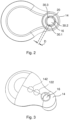
- This limited movement is determined by the difference between a height H of the opening 16 and the height h of the pin up to a knob 34 of the pin.
- the knob 34 of the pin has a diameter a bit greater than that of the opening 16, such that the knob 34, due to its being made of slightly flexible material, can be forced through the opening 16, whereupon the knob is above an outer surface 36 of the second module.
- the difference between the height H and the height h determines the distance over which, in use, the first and second module can move relative to each other in the direction of the axial axes 26 and 28. In other words, they can move relative to each other in a possible limited translation along an axis which is, at least substantially, perpendicular to the plane V mentioned.
- the possible limited translation is B centimeters at a maximum, where B is less than 6 cm, preferably less than 4 cm, and more preferably less than 2 cm.
- the first and second module can be connected with each other in three different rotational positions with respect to each other. For one of these positions, then, it holds that the sensor system 142 and the source 122 are situated, at least substantially, opposite each other, such that the radiation from the source is directed to the sensor system. If the grooves 30.2 and 30.3 as well as the ridges 32.2 and 32.3 are omitted, it holds that the first and second module can be connected with each other in one manner only, whereby in that case, in connected condition, the sensor system and the source are situated, at least substantially, opposite each other, such that the radiation of the source is directed at the sensor system.
- the measuring device is designed for pulsewise activating the light source, wherein the measuring signal is indicative of the value of the intensity measured during the pulsewise activation, wherein the measuring device is furthermore provided with synchronization means for synchronously activating the light source and the second module (14), wherein the synchronization means comprise an energy transmitting unit (126) which is part of one of the first and the second module and comprise a detector (148) which is part of the other one of the first and the second module, wherein in an operating condition the energy transmitting unit (126) pulsewise generates an electromagnetic field, and the detector receives this field and generates therefrom a supply voltage for use in that other module.
- the synchronization means comprise an energy transmitting unit (126) which is part of one of the first and the second module and comprise a detector (148) which is part of the other one of the first and the second module, wherein in an operating condition the energy transmitting unit (126) pulsewise generates an electromagnetic field, and the detector receives this field and generates therefrom a supply voltage for use in that other module.
- the energy transmitting unit and the detector are situated at least substantially opposite each other, such that the radiation of the energy transmitting unit is directed to the detector.
- the system comprises a measuring device 10 including the first module 12 and the second module 14.
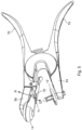
- the system further comprises a tool 52 including a first part 54 and a second part 56 which are connected movably relative to each other. Viewed from the first part 54, the second part 56 can move along a predetermined path P 3 towards the first part and away from the first part.
- the system is configured such that the first module 12 can be mechanically connected with the first part in an unequivocal manner.
- the tool is provided with a securing pin 58 (see Fig.
- the first module 12 is provided with a securing opening 60 in which the securing pin can be inserted for securing the first module to the tool.
- the securing opening and the securing pin have a complementary shape so that the first module and the tool can be mechanically connected with each other in one manner only.
- the securing opening 60 extends into the pin 18 of a first module to enable the first module to be mechanically connected with the tool in the unequivocal manner.
- the tool is furthermore provided with a hollow space 66 partly open to the outside, in which a second module can be received for mechanically connecting the second module with the tool in an unequivocal manner.
- the hollow space 66 and a part of an external side of the second module 14 have a complementary shape so that the second module and the tool can be mechanically connected with each other in one manner only.
- the second module 14 can be manipulated in the hollow space 66 and be retained, by means of a spring biased clip 70 and an end 71 of which can be moved by hand in the direction Q so that the second module can be received in the space 66 and of which the free end upon release is moved in the direction R so that the second module is retained in the hollow space 66.
- the tool in this example is implemented as a pair of pliers where the first and second part can be moved towards each other by moving two handles 72, 74 respectively towards each other.
- the pin 18 will automatically end up in the opening 16, that is, such that the ridge 32.1 is slid into the groove 30.1, the ridge 32.2 is slid into the groove 30.2, and the ridge 32.3 is slid into the groove 30.3.
- the first and second module can be attached to each other in three different ways (in each case with a difference in rotational position of 120 degrees around the axial axis of the pin), because by the use of the tool only one way of attachment is chosen.
- the grooves taking up the ridges a condition of the first and the second module being stably connected with each other is involved.
- 'stably' is here understood to mean that, after connection, still some limited rotation is possible because of tolerances, or in that this has been determined beforehand and that also in a direction perpendicular to the plane V, that is, in a direction of the axial axis of the pin 18, still a limited translation is possible of the first module relative to the second module to allow the measuring device to be comfortably fitted on the animal.
- the first module 12 includes a light source 122 for generating light L, an energy transmitting unit 126, and a control unit 125 for pulsewise activating the light source 122 and the energy transmitting unit 126.
- the second module 14 is provided with a sensor unit 142 and a detector 148.
- the control unit 125, the energy transmitting unit 126 and the detector 148 jointly form synchronization means for pulsewise activating the sensor unit 142 synchronously with the light source 122.
- a battery or other energy source (not shown) is included which supplies the electrical energy for the light source 122, the control unit 125 and the energy transmitting unit 126.
- the light source 122 is activated with control signal C1.
- the energy transmitting unit 126 upon activation by the control unit 125 with control signal C2, generates an electromagnetic field E.
- the detector 148 included in the second module 14 receives this electromagnetic field and generates therefrom a supply voltage, and also control signal C3 with which the sensor unit 142 is driven.
- the sensor unit 142 and the light source 122 are synchronously activated with the aid of the energy transmitting unit 126 and the detector 148.
- the points of time at which the sensor unit 142 and the light source 122 are activated are mutually correlated.
- measuring can be done reliably also with a relatively short pulse duration.
- the light source 122 and the sensor unit 142 can be fed from a common energy source.
- the activation points of time can coincide, but alternatively one of the activation points of time may be shifted by a predetermined time interval relative to the other activation point of time.
- the sensor unit 142 has a start-up time between the moment of receiving an activation signal C3 from the detector 148 and the moment at which it becomes actually operational. It may also be that the sensor unit 142 after detecting the light pulse Lm needs some time for processing, storage or forwarding information. This can be allowed for in an embodiment in which the control unit 125 activates the control signal C2 in a time interval that begins before the time interval of activating the control signal C1 and that ends following the time interval of activating the control signal C1. Another solution would be for the light source 122 to be activated during a time interval that is long enough for the sensor unit to function properly. This provides the advantage that control is simpler. However, the energy consumption by the light source 122 is higher then.
- the light source 122 is an infrared LED or OLED, but if desired an LED may be used for generating light in a different part of the light spectrum, for example, in the visible range, or in the ultraviolet range. Also, conceivably, a different type of light source is used. An LED or OLED, however, is the most suitable for this purpose since this type of light source can be easily driven at relatively low voltages and with a short pulse duration.
- the second module 14 has a sensor unit 142 for measuring an intensity of a fraction Lm of the generated light L, received via that skin part, for example the auricle.
- the measured intensity depends on inter alia the extent to which light en route from the light source 122 to the sensor unit 142 is absorbed by the blood in the veins and capillaries in that skin part H. This, in turn, depends on inter alia the diameter of the veins and capillaries. The diameter varies periodically with the frequency of the heartbeat. Hence, also the measured intensity varies with that same frequency. In addition, depending on the wavelength of the light, the absorption may depend to a greater or lesser extent on the concentration of constituents in the blood.
- the sensor unit can thus determine the frequency of the heartbeat as a condition parameter of the mammal from the measured intensity variations.
- the ridges 32.1-32.3 may be provided at an inner side of the opening 16 while the grooves 30.1-30.3 are provided on an outer side of the pin.
- the ridges are received in the grooves as discussed above ( Fig. 9 ).
- an inner side of the opening may be provided with ridges and grooves while an outer side of the pin is provided with grooves and ridges. In use, the ridges of the pin then fall into the grooves of the opening and the ridges of the opening then fall into the grooves of the pin ( Fig. 10 ).
- the first and second module may be provided with self-locating means which provide that the first and second module when being connected are turned relative to each other in a direction that corresponds with the at least one predetermined mutual orientation or with the predetermined range of mutual orientations.
- the grooves may for instance taper to obtain the self-locating effect and hence the self-locating means.
- the ridges it is possible for the ridges to taper in a direction in which the pin 18 is inserted into the opening to obtain the self-locating effect and hence the self-locating means.
Description
- The invention relates to a measuring device for measuring physiological data of an animal such as a mammal for determining at least one condition parameter of the animal, comprising a first and second module (12, 14) which are configured to be worn, in use, by the animal, wherein the first and second module are furthermore configured for them, from a condition of being mechanically separated from each other, to be mechanically connected with each other whereby in the connected condition, in use, between the first and second module is a skin part of the animal, wherein one of the modules comprises a source (122) for emitting electromagnetic radiation such as light (L) and wherein another of the modules comprises a sensor system (142) for measuring a parameter such as intensity of a fraction (Lm) of the emitted radiation (L) received via that skin part and for generating a measuring signal (SL) which is indicative of the measured parameter.
- A device of this type is known from
NL2015582 US 2017/100045 A1 . - A problem with such a device is that, in use, the source of one of the modules is not always optimally positioned with respect to the sensor system of the other module. According to the prior art, the first and second module are attached to each other by means of a pin/hole connection whereby, after the first and second modules have been connected with each other, the first and second module can be rotated relative to each other around an axial axis of the pin. Even if the first and second module are attached to each other such that the source is situated approximately opposite the sensor system, it can still happen that, in use, the first and second module rotate relative to each other, for instance in that someone inadvertently touches either of the parts, or in that the first and second module in the process of being attached to each other are still rotated relative to each other unnoticed.
- Object of the invention is to provide a solution to the problem mentioned. To that end, the measuring device according to the invention is characterized in that the measuring device is configured such that, in use, the first and second module can possibly have been connected or be connected (stably) with each other only when they have at least one mutual orientation that falls within a predetermined range of mutual orientations according to independent claim 1.
- Due to there being at least one mutual orientation where the first and second module can be connected with each other, it is only necessary, during connecting, to choose the right orientation where the first and second module can be connected with each other whereby in connected condition the sensor system and the source are situated opposite each other. Once the first and second module have been connected with each other in the correct manner, the position of the sensor system with respect to the source is maintained, remaining at least substantially unchanged.
- In particular, it holds that the first and second module can possibly have been connected or be connected (stably) with each other only when they have one mutual orientation that falls within a predetermined range of mutual orientations according to claim 1.
- In this manner, also when mechanically interconnecting the first module with the second module, no mistakes can be made anymore and it will always be ensured that the source is situated opposite the sensor system. The above-mentioned range of mutual orientations may be a consequence of tolerances but may also have been provided intentionally so that connecting the first module with the second module does not require absolute precision. It is only necessary that the first module and second module within a limited range take up the proper orientation with respect to each other for them to be connected with each other.
- It holds here that the range is limited in a possible limited turning around an axis which is at least substantially perpendicular to a plane which, in use, extends parallel to sides of the first and second module that face each other.
- More particularly, it holds here that the limited turning involves a maximum angle A, where A is less than 15 degrees, preferably less than 10 degrees and more preferably less than 5 degrees.
- In particular, it holds furthermore that the measuring device is configured such that if the first and second module, in use, have been attached to each other, the first and second module can move relative to each other in a possible limited translation along an axis which is at least substantially perpendicular to a plane which, in use, extends parallel to sides of the first and second module that face each other. It is thus ensured that also with varying thicknesses of the skin part, the first and second module can be comfortably attached to the animal.
- According to a practical embodiment, it holds that the second module is provided with a lead-through opening and the first module is provided with a projecting pin, while, in use, the pin extends through the opening.
- In addition to this, it holds in particular that an inner surface of the opening and an outer surface of the pin have a shape such that when an axial axis of the pin and an axial axis of the opening coincide, the pin can have been or be inserted into the opening only within at least one limited continuous range of rotation angles around its axial axis and with respect to the opening.
- According to a practical embodiment thereof, it holds that the outer surface is provided with at least one groove which extends in a length direction of the pin while the inner surface is provided with at least one ridge which, in use, extends in the groove and/or that the inner surface is provided with at least one groove which extends in a length direction of the opening while the outer surface is provided with at least one ridge which extends in the length direction of the pin and which, in use, extends in the groove.
- For the foregoing exemplary embodiments, it holds that when the first and second module have been connected with each other according to the one possibility or one of the possibilities, the sensor system and the source are situated at least substantially opposite each other, such that radiation from the source is directed to the sensor system (142). As mentioned, it holds preferably that the first and second module can be connected with each other only according to one possibility, so that, also during the actual connecting, that is, during the fitting to the animal, no mistakes can be made and the sensor system and source are always situated at least substantially opposite each other when the first and second module have been connected with each other. Approximately right positioning with respect to each other can be a consequence of tolerances to which the first and second module can be manufactured, but can also be a deliberate result of the design of the measuring device. In the latter case, it is thereby accomplished that, in use, upon attachment to the animal, it is only necessary that the first and second module, when being fitted to the animal, are positioned with respect to each other approximately in the right manner, which does not require absolute infinite precision.
- In particular, the measuring device is intended, with a relatively long useful life, to make measuring physiological data, such as the heartbeat of the mammal, possible.
- In realization of this, the measuring device provides in particular the possibility of measuring physiological data of a mammal for determining at least one condition parameter of the mammal. The measuring device accordingly comprises a measuring device to be worn by the mammal, having a first module and second module to be disposed mutually on opposite sides opposite a skin part of the mammal. The first module comprises the source for generating the radiation. The second module comprises the sensor unit for measuring an intensity of a fraction of the radiation received via that skin part and delivering a measuring signal which is indicative of the measured value of the radiation. The measuring device is preferably configured for pulsewise activating the source, while the measuring signal is indicative of the value of the intensity measured during the pulsewise activation. The measuring device may furthermore be provided with synchronization means for synchronously activating the source and the second module, while the synchronization means comprise an energy transmitting unit which is part of one of the first and the second module, and comprise a detector which is part of the other one of the first and the second module, while in an operating condition the energy transmitting unit pulsewise generates an electromagnetic field, and the detector receives this field and generates therefrom a supply voltage for use in that other module.
- The at least one condition parameter to be determined is, for example, a heartbeat of the animal or a blood pressure of the animal. Also, the condition parameter to be determined can be a blood value, i.e., an indication of a concentration of one or more constituents in the blood. Also, a combination of condition parameters can be established with the measuring device and/or the measuring method.
- As in the measuring device the radiation used for the measurement is preferably generated pulsewise, the intensity of the generated radiation can be raised without thereby also increasing the electrical energy consumption. Consequently, raising the intensity used does not need to be accompanied by a decrease of the useful life.
- The invention will now be further explained on the basis of the drawings, in which:
-
Fig. 1 shows a possible embodiment of a measuring device according to the invention; -
Fig. 2 shows a view of the second module in the direction of the arrow P1 ofFig. 1 ; -
Fig. 3 shows a view of the second module in the direction of the arrow P2 ofFig. 1 ; -
Fig. 4 shows a system according to the invention comprising a measuring device according to the invention and a tool; -
Fig. 5 shows the system ofFig. 4 when the first and second module have been attached to the tool; -
Fig. 6 shows the manner in which the first module can be attached to the tool; -
Fig. 7 schematically shows the measuring device ofFig. 1 ; -
Fig. 8 schematically shows components of the measuring device ofFig. 1 ; -
Fig. 9 schematically shows an alternative embodiment of an opening and pin of the device ofFig. 1 ; -
Fig. 10 schematically shows an alternative embodiment of an opening and pin of the device ofFig. 1 . - In
Figure 1 , withreference numeral 10 an embodiment of a measuring device according to the invention is designated. The measuring device is configured for measuring physiological data of an animal, such as a mammal, for determining at least one condition parameter of the animal. The device comprises afirst module 12 and asecond module 14 which are configured to be worn, in use, by the animal. The first and second module are configured for them, from a condition of being mechanically separated from each other as shown inFigure 1 , to be connected with each other, whereby in connected condition, in use, between the first and second module is a skin part of the animal, as is also shown inFigure 8 . - One of the two modules comprises a
source 122 for emitting electromagnetic rays such as light. In this example, this involves the second module (seeFig. 3 ). Another one of the modules, in this example thefirst module 12, is provided with asensor system 142 for measuring a parameter such as an intensity of a fraction (Lm) of the emitted radiation (L) received via the skin part, and for generating a measuring signal (SL) which is indicative of the measured parameter. - The
measuring device 10 is configured such that, in use, the first and second module can possibly have been connected (stably) with each other only when they have at least one predetermined mutual orientation or when they have at least one mutual orientation that falls within a predetermined range of mutual orientations. - In
Figure 1 , there is shown the mutual orientation of the first and second module where they can be connected with each other when the first and second module are moved towards each other in the direction of the arrow P1. - In this example, it holds that the second module is provided with a lead-through
opening 16 and thefirst module 12 is provided with a projectingpin 18, this pin, in use, extending through theopening 16. This situation is shown inFigure 8 . - An
inner surface 20 of theopening 16 and anouter surface 22 of thepin 18 have a shape such that when anaxial axis 26 of thepin 18 and anaxial axis 28 of theopening 16 coincide, the pin can have been or be inserted into the opening only within at least one (in this example three) limited continuous range of rotation angles φ around its axial axis and with respect to the opening. - In this example, this has been achieved in that the
inner surface 20 is provided with three grooves 30.1 - 30.3. Further, the outer surface of thepin 18 is provided with three ridges 32.1 - 32.3 which extend in the length direction of the pin and which, in use, respectively extend in the grooves 30.1 - 30.3. In this example, this means that the pin can be slid into the opening 16 in three rotational positions, indicated with the angle φ. These mutual positions differ by 120 degrees. Preferably, however, it holds that the ridges 32.2 and 32.3 as well as the grooves 30.2 and 30.3 are omitted, so that the pin can only be slid into the opening in one rotational position of the angle φ. - If a ridge has a thickness d as shown in
Figure 1 somewhat smaller than a width D of a groove as shown inFigure 2 , this has as a consequence that when the pin has been slid into the opening, it can rotate relative to the opening in a limited continuous range of rotation angles around an axial axis. This has as an advantage that when the pin is being fitted into the opening the ridges and grooves do not need to be perfectly aligned with each other for the pin to be slid into the opening. This applies both to the variant where the opening is provided with three grooves and the pin is provided with three ridges, the ridges being received in the respective grooves, and to the variant where the opening is only provided with a single groove 30.1 and the pin is provided with a corresponding single ridge 32.1. It holds, then, that the first and second module can possibly have been connected with each other only when they have a predetermined mutual orientation. In that case, the width of a groove is approximately equal to the width of a ridge. Or when they have a mutual orientation that falls within a predetermined range of mutual orientations (in that case, the width D of a groove is a bit greater than the thickness d of a ridge). Preferably, it holds in that case that the range is limited in a possible limited turning around the axis which is at least substantially perpendicular to a plane V which, in use, extends parallel to mutually facing sides A and B of the first and second module, respectively. This axis has the same direction as anaxial axis 26 of the pin and anaxial axis 28 of the opening. The above-mentioned limited turning is due to the ridge having a thickness less than the width of the groove, and involves for example a maximum angle in the direction of the angle φ, being less than 15 degrees, preferably less than 10 degrees and more preferably less than 5 degrees. - It holds furthermore that the measuring device is configured such that if the first and second module, in use, have been attached to each other, the first and second module can move relative to each other in a possible limited translation along an axis which is at least substantially perpendicular to a plane V which, in use, extends parallel to sides of the first and second module that face each other.
- This limited movement is determined by the difference between a height H of the
opening 16 and the height h of the pin up to aknob 34 of the pin. Theknob 34 of the pin has a diameter a bit greater than that of theopening 16, such that theknob 34, due to its being made of slightly flexible material, can be forced through theopening 16, whereupon the knob is above anouter surface 36 of the second module. The difference between the height H and the height h determines the distance over which, in use, the first and second module can move relative to each other in the direction of theaxial axes - The possible limited translation is B centimeters at a maximum, where B is less than 6 cm, preferably less than 4 cm, and more preferably less than 2 cm.
- In the example shown in
Figures 1 to 3 , then, the first and second module can be connected with each other in three different rotational positions with respect to each other. For one of these positions, then, it holds that thesensor system 142 and thesource 122 are situated, at least substantially, opposite each other, such that the radiation from the source is directed to the sensor system. If the grooves 30.2 and 30.3 as well as the ridges 32.2 and 32.3 are omitted, it holds that the first and second module can be connected with each other in one manner only, whereby in that case, in connected condition, the sensor system and the source are situated, at least substantially, opposite each other, such that the radiation of the source is directed at the sensor system. - Preferably, it holds that the measuring device is designed for pulsewise activating the light source, wherein the measuring signal is indicative of the value of the intensity measured during the pulsewise activation, wherein the measuring device is furthermore provided with synchronization means for synchronously activating the light source and the second module (14), wherein the synchronization means comprise an energy transmitting unit (126) which is part of one of the first and the second module and comprise a detector (148) which is part of the other one of the first and the second module, wherein in an operating condition the energy transmitting unit (126) pulsewise generates an electromagnetic field, and the detector receives this field and generates therefrom a supply voltage for use in that other module.
- All this will be explained in more detail hereinafter. At this point, however, it is relevant to mention that when the first and second module have been connected with each other according to the one possibility or one of the possibilities, the energy transmitting unit and the detector are situated at least substantially opposite each other, such that the radiation of the energy transmitting unit is directed to the detector.
- Again, it holds that when there are three possibilities of attaching the first and second module to each other, it holds only for the possibility where the ridge 32.1 is received in the groove 30.1, the ridge 32.2 is received in the groove 30.2, and the ridge 32.3 is received in the groove 30.3, that the energy transmitting unit and the detector are situated, at least substantially, opposite each other. Again, it holds that if the ridges 32.2 and 32.3 as well as the grooves 30.2 and 30.3 are omitted, there is only one possibility of connecting the first and second module with each other, whereby in this possibility the energy transmitting unit and the detector are situated opposite each other.
- Presently, with reference to
Figures 4-6 , a possible embodiment of a system according to the invention will be discussed. The system comprises a measuringdevice 10 including thefirst module 12 and thesecond module 14. The system further comprises atool 52 including afirst part 54 and asecond part 56 which are connected movably relative to each other. Viewed from thefirst part 54, thesecond part 56 can move along a predetermined path P3 towards the first part and away from the first part. The system is configured such that thefirst module 12 can be mechanically connected with the first part in an unequivocal manner. To this end, the tool is provided with a securing pin 58 (seeFig. 6 ) and thefirst module 12 is provided with a securingopening 60 in which the securing pin can be inserted for securing the first module to the tool. The securing opening and the securing pin have a complementary shape so that the first module and the tool can be mechanically connected with each other in one manner only. - In this example, this has been realized by providing the securing
pin 58 with aridge 62 and providing the securing opening with agroove 64. - In this example, it holds that the securing
opening 60 extends into thepin 18 of a first module to enable the first module to be mechanically connected with the tool in the unequivocal manner. The tool is furthermore provided with ahollow space 66 partly open to the outside, in which a second module can be received for mechanically connecting the second module with the tool in an unequivocal manner. Thehollow space 66 and a part of an external side of thesecond module 14 have a complementary shape so that the second module and the tool can be mechanically connected with each other in one manner only. In this example, thesecond module 14 can be manipulated in thehollow space 66 and be retained, by means of a springbiased clip 70 and anend 71 of which can be moved by hand in the direction Q so that the second module can be received in thespace 66 and of which the free end upon release is moved in the direction R so that the second module is retained in thehollow space 66. - The tool in this example is implemented as a pair of pliers where the first and second part can be moved towards each other by moving two
handles handles pin 18 will automatically end up in theopening 16, that is, such that the ridge 32.1 is slid into the groove 30.1, the ridge 32.2 is slid into the groove 30.2, and the ridge 32.3 is slid into the groove 30.3. It is noted here that presently it does not matter anymore that in the embodiment in which the first module has three ridges and the second module has three grooves the first and second module can be attached to each other in three different ways (in each case with a difference in rotational position of 120 degrees around the axial axis of the pin), because by the use of the tool only one way of attachment is chosen. As a result of the grooves taking up the ridges, a condition of the first and the second module being stably connected with each other is involved. Accordingly, 'stably' is here understood to mean that, after connection, still some limited rotation is possible because of tolerances, or in that this has been determined beforehand and that also in a direction perpendicular to the plane V, that is, in a direction of the axial axis of thepin 18, still a limited translation is possible of the first module relative to the second module to allow the measuring device to be comfortably fitted on the animal. - In
Figure 7 the measuring device is shown in use. Presently, it will be set out how the electronics of the measuring device may be implemented. This is only an exemplary embodiment which stands apart from the idea regarding the manner in which the first and second module can be connected with each other. - As further shown schematically in
Figure 8 , thefirst module 12 includes alight source 122 for generating light L, anenergy transmitting unit 126, and acontrol unit 125 for pulsewise activating thelight source 122 and theenergy transmitting unit 126. - The
second module 14 is provided with asensor unit 142 and adetector 148. Thecontrol unit 125, theenergy transmitting unit 126 and thedetector 148 jointly form synchronization means for pulsewise activating thesensor unit 142 synchronously with thelight source 122. In the first module 12 a battery or other energy source (not shown) is included which supplies the electrical energy for thelight source 122, thecontrol unit 125 and theenergy transmitting unit 126. Thelight source 122 is activated with control signal C1. Theenergy transmitting unit 126, upon activation by thecontrol unit 125 with control signal C2, generates an electromagnetic field E. Thedetector 148 included in thesecond module 14 receives this electromagnetic field and generates therefrom a supply voltage, and also control signal C3 with which thesensor unit 142 is driven. In the embodiment shown, thesensor unit 142 and thelight source 122 are synchronously activated with the aid of theenergy transmitting unit 126 and thedetector 148. In other words, the points of time at which thesensor unit 142 and thelight source 122 are activated are mutually correlated. As a result, measuring can be done reliably also with a relatively short pulse duration. Moreover, thelight source 122 and thesensor unit 142 can be fed from a common energy source. The activation points of time can coincide, but alternatively one of the activation points of time may be shifted by a predetermined time interval relative to the other activation point of time. It may be, for instance, that thesensor unit 142 has a start-up time between the moment of receiving an activation signal C3 from thedetector 148 and the moment at which it becomes actually operational. It may also be that thesensor unit 142 after detecting the light pulse Lm needs some time for processing, storage or forwarding information. This can be allowed for in an embodiment in which thecontrol unit 125 activates the control signal C2 in a time interval that begins before the time interval of activating the control signal C1 and that ends following the time interval of activating the control signal C1. Another solution would be for thelight source 122 to be activated during a time interval that is long enough for the sensor unit to function properly. This provides the advantage that control is simpler. However, the energy consumption by thelight source 122 is higher then. - In the embodiment shown, the
light source 122 is an infrared LED or OLED, but if desired an LED may be used for generating light in a different part of the light spectrum, for example, in the visible range, or in the ultraviolet range. Also, conceivably, a different type of light source is used. An LED or OLED, however, is the most suitable for this purpose since this type of light source can be easily driven at relatively low voltages and with a short pulse duration. - The
second module 14 has asensor unit 142 for measuring an intensity of a fraction Lm of the generated light L, received via that skin part, for example the auricle. - The measured intensity depends on inter alia the extent to which light en route from the
light source 122 to thesensor unit 142 is absorbed by the blood in the veins and capillaries in that skin part H. This, in turn, depends on inter alia the diameter of the veins and capillaries. The diameter varies periodically with the frequency of the heartbeat. Hence, also the measured intensity varies with that same frequency. In addition, depending on the wavelength of the light, the absorption may depend to a greater or lesser extent on the concentration of constituents in the blood. The sensor unit can thus determine the frequency of the heartbeat as a condition parameter of the mammal from the measured intensity variations. - The invention is not limited to the embodiments described. Thus, the ridges 32.1-32.3 may be provided at an inner side of the
opening 16 while the grooves 30.1-30.3 are provided on an outer side of the pin. In use, again, the ridges are received in the grooves as discussed above (Fig. 9 ). Also, an inner side of the opening may be provided with ridges and grooves while an outer side of the pin is provided with grooves and ridges. In use, the ridges of the pin then fall into the grooves of the opening and the ridges of the opening then fall into the grooves of the pin (Fig. 10 ). Also, it is possible for the first and second module to be provided with self-locating means which provide that the first and second module when being connected are turned relative to each other in a direction that corresponds with the at least one predetermined mutual orientation or with the predetermined range of mutual orientations. Thus, in a direction in which thepin 18 is inserted into the opening, the grooves may for instance taper to obtain the self-locating effect and hence the self-locating means. As an alternative, it is possible for the ridges to taper in a direction in which thepin 18 is inserted into the opening to obtain the self-locating effect and hence the self-locating means. The invention is limited by the scope of the appended claims.
Claims (21)
- A measuring device for measuring physiological data of an animal such as a mammal for determining at least one condition parameter of the animal, comprising a first and second module (12, 14) which are configured to be worn, in use, by the animal, wherein the first and second module are furthermore arranged to be mechanically connected with each other, from a condition of being mechanically separated from each other, whereby in the connected condition, in use, between the first and second module is a skin part of the animal, wherein one of the modules comprises a source (122) for emitting electromagnetic radiation such as light (L) and wherein another of the modules comprises a sensor system (142) for measuring a parameter such as intensity of a fraction (Lm) of the emitted radiation (L) received via that skin part and for generating a measuring signal (SL) which is indicative of the measured parameter, wherein the measuring device is configured such that, in use, the first and second module can be connected stably with each other only when they have at least one mutual orientation that falls within a predetermined range of mutual orientations, characterized in that the range is limited in a limited turning around an axis which is at least substantially perpendicular to a plane which, in use, extends parallel to sides of the first and second module that face each other.
- The measuring device according to claim 1, characterized in that the first and second module can possibly have been connected or be connected (stably) with each other only when they have one mutual orientation that falls within the predetermined range of mutual orientations.
- The measuring device according to claim 1 or 2, characterized in that the limited turning involves a maximum angle A where A is less than 15 degrees, preferably less than 10 degrees and more preferably less than 5 degrees.
- The measuring device according to any one of the preceding claims, characterized in that the measuring device is configured such that if the first and second module, in use, have been attached to each other, the first and second module can move relative to each other in a possible limited translation along an axis which is at least substantially perpendicular to a plane which, in use, extends parallel to sides of the first and second module that face each other.
- The measuring device according to claim 4, characterized in that the possible limited translation is B cm at a maximum, where B is less than 6 cm, preferably less than 4 cm, and more preferably less than 2 cm.
- The measuring device according to any one of the preceding claims, characterized in that the first and second module are provided with self-locating means which provide that in connecting the first and second module the first and second module are turned relative to each other in a direction which corresponds to the predetermined range of mutual orientations.
- The measuring device according to any one of the preceding claims, characterized in that the second module is provided with a lead-through opening and the first module is provided with a projecting pin, while, in use, the pin extends through the opening.
- The measuring device according to claim 7, characterized in that an inner surface of the opening and an outer surface of the pin have a shape such that when an axial axis of the pin and an axial axis of the opening coincide, the pin can have been or be inserted into the opening only within at least one limited continuous range of rotation angles around its axial axis and with respect to the opening.
- The measuring device according to claim 8, characterized in that the range is A, where A is less than 15 degrees, preferably less than 10 degrees, and more preferably less than 5 degrees.
- The measuring device according to claim 8 or 9, characterized in that the outer surface is provided with at least one groove which extends in a length direction of the pin while the inner surface is provided with at least one ridge which, in use, extends in the groove and/or that the inner surface is provided with at least one groove which extends in a length direction of the opening while the outer surface is provided with at least one ridge which extends in the length direction of the pin and which, in use, extends in the groove.
- The measuring device according to any one of the preceding claims, characterized in that when the first and second module have been connected with each other according to the one possibility or one of the possibilities, the sensor system (142) and the source (122) are situated at least substantially opposite each other, such that radiation from the source is directed to the sensor system (142).
- The measuring device according to any one of the preceding claims, characterized in that the measuring device is configured for pulsewise activating the light source, wherein the measuring signal is indicative of the value of the intensity measured during the pulsewise activation, wherein the measuring device is furthermore provided with synchronization means for synchronously activating the light source and the second module (14), wherein the synchronization means comprise an energy transmitting unit (126) which is part of one of the first and the second module and comprise a detector (148) which is part of the other one of the first and the second module, wherein in an operating condition the energy transmitting unit (126) pulsewise generates an electromagnetic field, and the detector receives this field and generates therefrom a supply voltage for use in that other module.
- The measuring device according to claim 12, characterized in that the measuring device is configured such that, in use, the synchronization means (125) pulsewise activates the light source (122) and the energy transmitting unit (126), wherein the detector (148) pulsewise activates the sensor means (142) in response to the energy received from the energy transmitting unit (126) or that the synchronization means (145) pulsewise activates the sensor means (142) and the energy transmitting unit (126), wherein the detector (148) pulsewise activates the light source (122) in response to the energy received from the energy transmitting unit (126).
- The measuring device according to claim 12 or 13, characterized in that when the first and second module have been connected with each other according to the one possibility or one of the possibilities, the energy transmitting unit and the detector are situated at least substantially opposite each other, such that radiation from the energy transmitting unit is directed to the detector.
- A system comprising a measuring device according to any one of the preceding claims, characterized in that the system comprises a tool including a first part and a second part which are connected movably relative to each other, wherein, viewed from the first part, the second part can move along a predetermined path towards the first part and away from the first part, the system being configured such that the first module can be mechanically connected to the first part in one unequivocal manner and the second module can be mechanically connected to the second part in one unequivocal manner, wherein if the first part and the second part are moved towards each other the first and second module are (stably) connected with each other while they have the predetermined mutual orientation; or have the mutual orientation that falls within the predetermined range of mutual orientations.
- The system according to claim 15, characterized in that the tool is implemented as a pair of pliers of which the first part and the second part can be moved towards each other by moving two handles of the pliers towards each other.
- The system according to claim 15 or 16, characterized in that the tool is provided with a securing pin and the first module is provided with a securing opening in which the securing pin can be inserted for securing the first module to the tool.
- The system according to claim 17, characterized in that the securing opening extends into the pin of the first module according to claim 5 for mechanically connecting the first module with the tool in the unequivocal manner.
- The system according to claim 18, characterized in that the securing opening and the securing pin have a complementary shape so that the first module and the tool can be mechanically connected with each other in one manner only.
- The system according to any one of claims 15-19, characterized in that the tool is provided with a hollow space partly open to the outside in which the second module can be received for mechanically connecting the second module with the tool in the unequivocal manner.
- The system according to claim 20, characterized in that the hollow space and a part of an outer side of the second module have a complementary shape so that the second module and the tool can be mechanically connected with each other in one manner only.
Applications Claiming Priority (2)
| Application Number | Priority Date | Filing Date | Title |
|---|---|---|---|
| NL2020993A NL2020993B1 (en) | 2018-05-28 | 2018-05-28 | Measuring apparatus and method for measuring physiological data from a mammal |
| PCT/NL2019/050306 WO2019231318A1 (en) | 2018-05-28 | 2019-05-28 | Measuring device for measuring physiological data of a mammal |
Publications (2)
| Publication Number | Publication Date |
|---|---|
| EP3801231A1 EP3801231A1 (en) | 2021-04-14 |
| EP3801231B1 true EP3801231B1 (en) | 2023-03-15 |
Family
ID=62873540
Family Applications (1)
| Application Number | Title | Priority Date | Filing Date |
|---|---|---|---|
| EP19743017.6A Active EP3801231B1 (en) | 2018-05-28 | 2019-05-28 | Measuring device for measuring physiological data of a mammal |
Country Status (4)
| Country | Link |
|---|---|
| US (1) | US20210219856A1 (en) |
| EP (1) | EP3801231B1 (en) |
| NL (1) | NL2020993B1 (en) |
| WO (1) | WO2019231318A1 (en) |
Families Citing this family (1)
| Publication number | Priority date | Publication date | Assignee | Title |
|---|---|---|---|---|
| CN115016244B (en) * | 2021-03-05 | 2023-06-27 | Oppo广东移动通信有限公司 | Information processing method, wearable system, and computer-readable storage medium |
Family Cites Families (5)
| Publication number | Priority date | Publication date | Assignee | Title |
|---|---|---|---|---|
| US5800349A (en) * | 1996-10-15 | 1998-09-01 | Nonin Medical, Inc. | Offset pulse oximeter sensor |
| NL2015582B1 (en) | 2015-10-07 | 2017-05-02 | N V Nederlandsche Apparatenfabriek Nedap | Measuring apparatus and method for measuring physiological data from a mammal. |
| CN109414196B (en) * | 2016-07-08 | 2021-12-14 | 皇家飞利浦有限公司 | Device and method for measuring physiological parameters of a human limb |
| WO2018022987A1 (en) * | 2016-07-29 | 2018-02-01 | Cattle Time, Llc | Button and applicator for animal identification tags |
| US11166799B2 (en) * | 2017-05-19 | 2021-11-09 | Maxim Integrated Products, Inc. | Physiological condition determination system |
-
2018
- 2018-05-28 NL NL2020993A patent/NL2020993B1/en active
-
2019
- 2019-05-28 EP EP19743017.6A patent/EP3801231B1/en active Active
- 2019-05-28 WO PCT/NL2019/050306 patent/WO2019231318A1/en unknown
- 2019-05-28 US US17/058,859 patent/US20210219856A1/en active Pending
Also Published As
| Publication number | Publication date |
|---|---|
| US20210219856A1 (en) | 2021-07-22 |
| EP3801231A1 (en) | 2021-04-14 |
| NL2020993B1 (en) | 2019-12-03 |
| WO2019231318A1 (en) | 2019-12-05 |
Similar Documents
| Publication | Publication Date | Title |
|---|---|---|
| EP3060138B1 (en) | Surgical tool systems | |
| US11109922B2 (en) | Surgical tool systems and method | |
| JP7107635B2 (en) | Surgical tool system and method | |
| US11607149B2 (en) | Surgical tool systems and method | |
| US5352039A (en) | Remote temperature and/or temperature difference measuring device | |
| US8695266B2 (en) | Reference beam generating apparatus | |
| EP3801231B1 (en) | Measuring device for measuring physiological data of a mammal | |
| EP2112456A2 (en) | Device and method for a sighting apparatus | |
| US10600596B2 (en) | Adapter to attach implements to an actively controlled human tremor cancellation platform | |
| CA2541635A1 (en) | Hybrid sensing apparatus for adaptive robotic processes | |
| US20210236212A1 (en) | Tracker for a Surgical Instrument | |
| US9405171B2 (en) | Laser illumination device with integrated shutter | |
| CN108454877B (en) | Adjustment tool for a control surface of an aircraft | |
| US20030177652A1 (en) | Laser centering device | |
| KR20220010732A (en) | Electric Surgical Drill with Rotating Field Bit Identification | |
| ES2383839T3 (en) | Methods and apparatus for a pin or instrumented fastener | |
| US20100108800A1 (en) | Object detection system having an image detection system | |
| US9168106B2 (en) | Device and method for instrument adjustment in computer assisted surgery | |
| CN115670576A (en) | Bone nail registration auxiliary mechanism, bone nail registration system and method | |
| CN113518593A (en) | Surgical instrument | |
| ES2669195T3 (en) | Active system for the detection of a target object | |
| KR102627848B1 (en) | Electronic controller with hand retainer, outer shell and finger detection | |
| CN111938815A (en) | Tracker for surgical navigation system | |
| US8692691B2 (en) | Infrared laser landing marker | |
| CN211180501U (en) | High-precision line light source adjusting structure |
Legal Events
| Date | Code | Title | Description |
|---|---|---|---|
| STAA | Information on the status of an ep patent application or granted ep patent |
Free format text: STATUS: UNKNOWN |
|
| STAA | Information on the status of an ep patent application or granted ep patent |
Free format text: STATUS: THE INTERNATIONAL PUBLICATION HAS BEEN MADE |
|
| STAA | Information on the status of an ep patent application or granted ep patent |
Free format text: STATUS: THE INTERNATIONAL PUBLICATION HAS BEEN MADE |
|
| PUAI | Public reference made under article 153(3) epc to a published international application that has entered the european phase |
Free format text: ORIGINAL CODE: 0009012 |
|
| STAA | Information on the status of an ep patent application or granted ep patent |
Free format text: STATUS: REQUEST FOR EXAMINATION WAS MADE |
|
| 17P | Request for examination filed |
Effective date: 20201201 |
|
| AK | Designated contracting states |
Kind code of ref document: A1 Designated state(s): AL AT BE BG CH CY CZ DE DK EE ES FI FR GB GR HR HU IE IS IT LI LT LU LV MC MK MT NL NO PL PT RO RS SE SI SK SM TR |
|
| AX | Request for extension of the european patent |
Extension state: BA ME |
|
| DAV | Request for validation of the european patent (deleted) | ||
| DAX | Request for extension of the european patent (deleted) | ||
| STAA | Information on the status of an ep patent application or granted ep patent |
Free format text: STATUS: EXAMINATION IS IN PROGRESS |
|
| 17Q | First examination report despatched |
Effective date: 20211130 |
|
| GRAP | Despatch of communication of intention to grant a patent |
Free format text: ORIGINAL CODE: EPIDOSNIGR1 |
|
| STAA | Information on the status of an ep patent application or granted ep patent |
Free format text: STATUS: GRANT OF PATENT IS INTENDED |
|
| INTG | Intention to grant announced |
Effective date: 20221018 |
|
| GRAS | Grant fee paid |
Free format text: ORIGINAL CODE: EPIDOSNIGR3 |
|
| GRAA | (expected) grant |
Free format text: ORIGINAL CODE: 0009210 |
|
| STAA | Information on the status of an ep patent application or granted ep patent |
Free format text: STATUS: THE PATENT HAS BEEN GRANTED |
|
| AK | Designated contracting states |
Kind code of ref document: B1 Designated state(s): AL AT BE BG CH CY CZ DE DK EE ES FI FR GB GR HR HU IE IS IT LI LT LU LV MC MK MT NL NO PL PT RO RS SE SI SK SM TR |
|
| REG | Reference to a national code |
Ref country code: CH Ref legal event code: EP Ref country code: GB Ref legal event code: FG4D |
|
| REG | Reference to a national code |
Ref country code: DE Ref legal event code: R096 Ref document number: 602019026429 Country of ref document: DE |
|
| REG | Reference to a national code |
Ref country code: IE Ref legal event code: FG4D |
|
| REG | Reference to a national code |
Ref country code: AT Ref legal event code: REF Ref document number: 1553519 Country of ref document: AT Kind code of ref document: T Effective date: 20230415 |
|
| REG | Reference to a national code |
Ref country code: NL Ref legal event code: FP |
|
| PGFP | Annual fee paid to national office [announced via postgrant information from national office to epo] |
Ref country code: NL Payment date: 20230425 Year of fee payment: 5 |
|
| P01 | Opt-out of the competence of the unified patent court (upc) registered |
Effective date: 20230525 |
|
| REG | Reference to a national code |
Ref country code: LT Ref legal event code: MG9D |
|
| PG25 | Lapsed in a contracting state [announced via postgrant information from national office to epo] |
Ref country code: RS Free format text: LAPSE BECAUSE OF FAILURE TO SUBMIT A TRANSLATION OF THE DESCRIPTION OR TO PAY THE FEE WITHIN THE PRESCRIBED TIME-LIMIT Effective date: 20230315 Ref country code: NO Free format text: LAPSE BECAUSE OF FAILURE TO SUBMIT A TRANSLATION OF THE DESCRIPTION OR TO PAY THE FEE WITHIN THE PRESCRIBED TIME-LIMIT Effective date: 20230615 Ref country code: LV Free format text: LAPSE BECAUSE OF FAILURE TO SUBMIT A TRANSLATION OF THE DESCRIPTION OR TO PAY THE FEE WITHIN THE PRESCRIBED TIME-LIMIT Effective date: 20230315 Ref country code: LT Free format text: LAPSE BECAUSE OF FAILURE TO SUBMIT A TRANSLATION OF THE DESCRIPTION OR TO PAY THE FEE WITHIN THE PRESCRIBED TIME-LIMIT Effective date: 20230315 Ref country code: HR Free format text: LAPSE BECAUSE OF FAILURE TO SUBMIT A TRANSLATION OF THE DESCRIPTION OR TO PAY THE FEE WITHIN THE PRESCRIBED TIME-LIMIT Effective date: 20230315 |
|
| PGFP | Annual fee paid to national office [announced via postgrant information from national office to epo] |
Ref country code: DE Payment date: 20230519 Year of fee payment: 5 |
|
| REG | Reference to a national code |
Ref country code: AT Ref legal event code: MK05 Ref document number: 1553519 Country of ref document: AT Kind code of ref document: T Effective date: 20230315 |
|
| PG25 | Lapsed in a contracting state [announced via postgrant information from national office to epo] |
Ref country code: SE Free format text: LAPSE BECAUSE OF FAILURE TO SUBMIT A TRANSLATION OF THE DESCRIPTION OR TO PAY THE FEE WITHIN THE PRESCRIBED TIME-LIMIT Effective date: 20230315 Ref country code: GR Free format text: LAPSE BECAUSE OF FAILURE TO SUBMIT A TRANSLATION OF THE DESCRIPTION OR TO PAY THE FEE WITHIN THE PRESCRIBED TIME-LIMIT Effective date: 20230616 Ref country code: FI Free format text: LAPSE BECAUSE OF FAILURE TO SUBMIT A TRANSLATION OF THE DESCRIPTION OR TO PAY THE FEE WITHIN THE PRESCRIBED TIME-LIMIT Effective date: 20230315 |
|
| PG25 | Lapsed in a contracting state [announced via postgrant information from national office to epo] |
Ref country code: SM Free format text: LAPSE BECAUSE OF FAILURE TO SUBMIT A TRANSLATION OF THE DESCRIPTION OR TO PAY THE FEE WITHIN THE PRESCRIBED TIME-LIMIT Effective date: 20230315 Ref country code: RO Free format text: LAPSE BECAUSE OF FAILURE TO SUBMIT A TRANSLATION OF THE DESCRIPTION OR TO PAY THE FEE WITHIN THE PRESCRIBED TIME-LIMIT Effective date: 20230315 Ref country code: PT Free format text: LAPSE BECAUSE OF FAILURE TO SUBMIT A TRANSLATION OF THE DESCRIPTION OR TO PAY THE FEE WITHIN THE PRESCRIBED TIME-LIMIT Effective date: 20230717 Ref country code: ES Free format text: LAPSE BECAUSE OF FAILURE TO SUBMIT A TRANSLATION OF THE DESCRIPTION OR TO PAY THE FEE WITHIN THE PRESCRIBED TIME-LIMIT Effective date: 20230315 Ref country code: EE Free format text: LAPSE BECAUSE OF FAILURE TO SUBMIT A TRANSLATION OF THE DESCRIPTION OR TO PAY THE FEE WITHIN THE PRESCRIBED TIME-LIMIT Effective date: 20230315 Ref country code: CZ Free format text: LAPSE BECAUSE OF FAILURE TO SUBMIT A TRANSLATION OF THE DESCRIPTION OR TO PAY THE FEE WITHIN THE PRESCRIBED TIME-LIMIT Effective date: 20230315 Ref country code: AT Free format text: LAPSE BECAUSE OF FAILURE TO SUBMIT A TRANSLATION OF THE DESCRIPTION OR TO PAY THE FEE WITHIN THE PRESCRIBED TIME-LIMIT Effective date: 20230315 |
|
| PG25 | Lapsed in a contracting state [announced via postgrant information from national office to epo] |
Ref country code: SK Free format text: LAPSE BECAUSE OF FAILURE TO SUBMIT A TRANSLATION OF THE DESCRIPTION OR TO PAY THE FEE WITHIN THE PRESCRIBED TIME-LIMIT Effective date: 20230315 Ref country code: PL Free format text: LAPSE BECAUSE OF FAILURE TO SUBMIT A TRANSLATION OF THE DESCRIPTION OR TO PAY THE FEE WITHIN THE PRESCRIBED TIME-LIMIT Effective date: 20230315 Ref country code: IS Free format text: LAPSE BECAUSE OF FAILURE TO SUBMIT A TRANSLATION OF THE DESCRIPTION OR TO PAY THE FEE WITHIN THE PRESCRIBED TIME-LIMIT Effective date: 20230715 |
|
| REG | Reference to a national code |
Ref country code: DE Ref legal event code: R097 Ref document number: 602019026429 Country of ref document: DE |
|
| REG | Reference to a national code |
Ref country code: CH Ref legal event code: PL |
|
| PG25 | Lapsed in a contracting state [announced via postgrant information from national office to epo] |
Ref country code: MC Free format text: LAPSE BECAUSE OF FAILURE TO SUBMIT A TRANSLATION OF THE DESCRIPTION OR TO PAY THE FEE WITHIN THE PRESCRIBED TIME-LIMIT Effective date: 20230315 |
|
| PLBE | No opposition filed within time limit |
Free format text: ORIGINAL CODE: 0009261 |
|
| STAA | Information on the status of an ep patent application or granted ep patent |
Free format text: STATUS: NO OPPOSITION FILED WITHIN TIME LIMIT |
|
| REG | Reference to a national code |
Ref country code: BE Ref legal event code: MM Effective date: 20230531 |
|
| PG25 | Lapsed in a contracting state [announced via postgrant information from national office to epo] |
Ref country code: SI Free format text: LAPSE BECAUSE OF FAILURE TO SUBMIT A TRANSLATION OF THE DESCRIPTION OR TO PAY THE FEE WITHIN THE PRESCRIBED TIME-LIMIT Effective date: 20230315 Ref country code: MC Free format text: LAPSE BECAUSE OF FAILURE TO SUBMIT A TRANSLATION OF THE DESCRIPTION OR TO PAY THE FEE WITHIN THE PRESCRIBED TIME-LIMIT Effective date: 20230315 Ref country code: LU Free format text: LAPSE BECAUSE OF NON-PAYMENT OF DUE FEES Effective date: 20230528 Ref country code: LI Free format text: LAPSE BECAUSE OF NON-PAYMENT OF DUE FEES Effective date: 20230531 Ref country code: DK Free format text: LAPSE BECAUSE OF FAILURE TO SUBMIT A TRANSLATION OF THE DESCRIPTION OR TO PAY THE FEE WITHIN THE PRESCRIBED TIME-LIMIT Effective date: 20230315 Ref country code: CH Free format text: LAPSE BECAUSE OF NON-PAYMENT OF DUE FEES Effective date: 20230531 |
|
| 26N | No opposition filed |
Effective date: 20231218 |
|
| GBPC | Gb: european patent ceased through non-payment of renewal fee |
Effective date: 20230615 |
|
| REG | Reference to a national code |
Ref country code: IE Ref legal event code: MM4A |
|
| PG25 | Lapsed in a contracting state [announced via postgrant information from national office to epo] |
Ref country code: IE Free format text: LAPSE BECAUSE OF NON-PAYMENT OF DUE FEES Effective date: 20230528 |
|
| PG25 | Lapsed in a contracting state [announced via postgrant information from national office to epo] |
Ref country code: IE Free format text: LAPSE BECAUSE OF NON-PAYMENT OF DUE FEES Effective date: 20230528 Ref country code: GB Free format text: LAPSE BECAUSE OF NON-PAYMENT OF DUE FEES Effective date: 20230615 |