EP3801089B1 - Dispositif de génération d'aérosol ayant un composant mobile de transfert de substrat de formation d'aérosol - Google Patents
Dispositif de génération d'aérosol ayant un composant mobile de transfert de substrat de formation d'aérosol Download PDFInfo
- Publication number
- EP3801089B1 EP3801089B1 EP19728703.0A EP19728703A EP3801089B1 EP 3801089 B1 EP3801089 B1 EP 3801089B1 EP 19728703 A EP19728703 A EP 19728703A EP 3801089 B1 EP3801089 B1 EP 3801089B1
- Authority
- EP
- European Patent Office
- Prior art keywords
- transfer element
- heating
- aerosol
- heating element
- forming substrate
- Prior art date
- Legal status (The legal status is an assumption and is not a legal conclusion. Google has not performed a legal analysis and makes no representation as to the accuracy of the status listed.)
- Active
Links
- 239000000758 substrate Substances 0.000 title claims description 101
- 238000010438 heat treatment Methods 0.000 claims description 162
- 239000007788 liquid Substances 0.000 claims description 112
- 239000000443 aerosol Substances 0.000 claims description 20
- 230000000717 retained effect Effects 0.000 claims description 10
- 239000012530 fluid Substances 0.000 claims description 9
- 238000001514 detection method Methods 0.000 claims description 5
- 239000000463 material Substances 0.000 description 33
- 239000012876 carrier material Substances 0.000 description 12
- 239000011344 liquid material Substances 0.000 description 4
- 230000000704 physical effect Effects 0.000 description 4
- -1 polyethylene Polymers 0.000 description 4
- 241000208125 Nicotiana Species 0.000 description 3
- 235000002637 Nicotiana tabacum Nutrition 0.000 description 3
- DNIAPMSPPWPWGF-UHFFFAOYSA-N Propylene glycol Chemical compound CC(O)CO DNIAPMSPPWPWGF-UHFFFAOYSA-N 0.000 description 3
- 150000001875 compounds Chemical class 0.000 description 3
- 238000011144 upstream manufacturing Methods 0.000 description 3
- PUPZLCDOIYMWBV-UHFFFAOYSA-N (+/-)-1,3-Butanediol Chemical compound CC(O)CCO PUPZLCDOIYMWBV-UHFFFAOYSA-N 0.000 description 2
- OKTJSMMVPCPJKN-UHFFFAOYSA-N Carbon Chemical compound [C] OKTJSMMVPCPJKN-UHFFFAOYSA-N 0.000 description 2
- LFQSCWFLJHTTHZ-UHFFFAOYSA-N Ethanol Chemical compound CCO LFQSCWFLJHTTHZ-UHFFFAOYSA-N 0.000 description 2
- PEDCQBHIVMGVHV-UHFFFAOYSA-N Glycerine Chemical compound OCC(O)CO PEDCQBHIVMGVHV-UHFFFAOYSA-N 0.000 description 2
- 239000004677 Nylon Substances 0.000 description 2
- 239000004698 Polyethylene Substances 0.000 description 2
- 239000004743 Polypropylene Substances 0.000 description 2
- 229920004933 Terylene® Polymers 0.000 description 2
- 229920002301 cellulose acetate Polymers 0.000 description 2
- 239000000919 ceramic Substances 0.000 description 2
- 239000002657 fibrous material Substances 0.000 description 2
- 239000000796 flavoring agent Substances 0.000 description 2
- 235000019634 flavors Nutrition 0.000 description 2
- 239000006261 foam material Substances 0.000 description 2
- 229910002804 graphite Inorganic materials 0.000 description 2
- 239000010439 graphite Substances 0.000 description 2
- 239000002184 metal Substances 0.000 description 2
- 229920001778 nylon Polymers 0.000 description 2
- 239000004033 plastic Substances 0.000 description 2
- 229920003023 plastic Polymers 0.000 description 2
- 229920000728 polyester Polymers 0.000 description 2
- 229920000573 polyethylene Polymers 0.000 description 2
- 239000005020 polyethylene terephthalate Substances 0.000 description 2
- 229920000642 polymer Polymers 0.000 description 2
- 229920000098 polyolefin Polymers 0.000 description 2
- 229920001155 polypropylene Polymers 0.000 description 2
- 239000000843 powder Substances 0.000 description 2
- 230000000391 smoking effect Effects 0.000 description 2
- SNICXCGAKADSCV-JTQLQIEISA-N (-)-Nicotine Chemical compound CN1CCC[C@H]1C1=CC=CN=C1 SNICXCGAKADSCV-JTQLQIEISA-N 0.000 description 1
- 230000015572 biosynthetic process Effects 0.000 description 1
- 238000009835 boiling Methods 0.000 description 1
- 229920001577 copolymer Polymers 0.000 description 1
- 239000010419 fine particle Substances 0.000 description 1
- 239000006260 foam Substances 0.000 description 1
- 239000007789 gas Substances 0.000 description 1
- 235000011187 glycerol Nutrition 0.000 description 1
- 230000005484 gravity Effects 0.000 description 1
- 230000014759 maintenance of location Effects 0.000 description 1
- 239000000203 mixture Substances 0.000 description 1
- 229960002715 nicotine Drugs 0.000 description 1
- SNICXCGAKADSCV-UHFFFAOYSA-N nicotine Natural products CN1CCCC1C1=CC=CN=C1 SNICXCGAKADSCV-UHFFFAOYSA-N 0.000 description 1
- 239000000419 plant extract Substances 0.000 description 1
- 238000004321 preservation Methods 0.000 description 1
- 230000004044 response Effects 0.000 description 1
- 239000007787 solid Substances 0.000 description 1
- 239000002904 solvent Substances 0.000 description 1
- 239000000126 substance Substances 0.000 description 1
- 150000005846 sugar alcohols Polymers 0.000 description 1
- ZIBGPFATKBEMQZ-UHFFFAOYSA-N triethylene glycol Chemical compound OCCOCCOCCO ZIBGPFATKBEMQZ-UHFFFAOYSA-N 0.000 description 1
- XLYOFNOQVPJJNP-UHFFFAOYSA-N water Substances O XLYOFNOQVPJJNP-UHFFFAOYSA-N 0.000 description 1
Images
Classifications
-
- A—HUMAN NECESSITIES
- A24—TOBACCO; CIGARS; CIGARETTES; SIMULATED SMOKING DEVICES; SMOKERS' REQUISITES
- A24F—SMOKERS' REQUISITES; MATCH BOXES; SIMULATED SMOKING DEVICES
- A24F40/00—Electrically operated smoking devices; Component parts thereof; Manufacture thereof; Maintenance or testing thereof; Charging means specially adapted therefor
- A24F40/40—Constructional details, e.g. connection of cartridges and battery parts
- A24F40/44—Wicks
-
- A—HUMAN NECESSITIES
- A24—TOBACCO; CIGARS; CIGARETTES; SIMULATED SMOKING DEVICES; SMOKERS' REQUISITES
- A24F—SMOKERS' REQUISITES; MATCH BOXES; SIMULATED SMOKING DEVICES
- A24F40/00—Electrically operated smoking devices; Component parts thereof; Manufacture thereof; Maintenance or testing thereof; Charging means specially adapted therefor
- A24F40/40—Constructional details, e.g. connection of cartridges and battery parts
-
- A—HUMAN NECESSITIES
- A24—TOBACCO; CIGARS; CIGARETTES; SIMULATED SMOKING DEVICES; SMOKERS' REQUISITES
- A24F—SMOKERS' REQUISITES; MATCH BOXES; SIMULATED SMOKING DEVICES
- A24F40/00—Electrically operated smoking devices; Component parts thereof; Manufacture thereof; Maintenance or testing thereof; Charging means specially adapted therefor
- A24F40/10—Devices using liquid inhalable precursors
-
- A—HUMAN NECESSITIES
- A24—TOBACCO; CIGARS; CIGARETTES; SIMULATED SMOKING DEVICES; SMOKERS' REQUISITES
- A24F—SMOKERS' REQUISITES; MATCH BOXES; SIMULATED SMOKING DEVICES
- A24F40/00—Electrically operated smoking devices; Component parts thereof; Manufacture thereof; Maintenance or testing thereof; Charging means specially adapted therefor
- A24F40/40—Constructional details, e.g. connection of cartridges and battery parts
- A24F40/42—Cartridges or containers for inhalable precursors
-
- A—HUMAN NECESSITIES
- A24—TOBACCO; CIGARS; CIGARETTES; SIMULATED SMOKING DEVICES; SMOKERS' REQUISITES
- A24F—SMOKERS' REQUISITES; MATCH BOXES; SIMULATED SMOKING DEVICES
- A24F40/00—Electrically operated smoking devices; Component parts thereof; Manufacture thereof; Maintenance or testing thereof; Charging means specially adapted therefor
- A24F40/40—Constructional details, e.g. connection of cartridges and battery parts
- A24F40/46—Shape or structure of electric heating means
-
- A—HUMAN NECESSITIES
- A24—TOBACCO; CIGARS; CIGARETTES; SIMULATED SMOKING DEVICES; SMOKERS' REQUISITES
- A24F—SMOKERS' REQUISITES; MATCH BOXES; SIMULATED SMOKING DEVICES
- A24F40/00—Electrically operated smoking devices; Component parts thereof; Manufacture thereof; Maintenance or testing thereof; Charging means specially adapted therefor
- A24F40/40—Constructional details, e.g. connection of cartridges and battery parts
- A24F40/48—Fluid transfer means, e.g. pumps
-
- A—HUMAN NECESSITIES
- A24—TOBACCO; CIGARS; CIGARETTES; SIMULATED SMOKING DEVICES; SMOKERS' REQUISITES
- A24F—SMOKERS' REQUISITES; MATCH BOXES; SIMULATED SMOKING DEVICES
- A24F40/00—Electrically operated smoking devices; Component parts thereof; Manufacture thereof; Maintenance or testing thereof; Charging means specially adapted therefor
- A24F40/50—Control or monitoring
- A24F40/53—Monitoring, e.g. fault detection
Definitions
- the present invention relates to an aerosol-generating device that operates by heating an aerosol-forming substrate.
- the invention relates to handheld aerosol-generating devices which vaporise a liquid aerosol-forming substrate by heating to generate an aerosol for inhalation by a user.
- an electric heater comprising at least one resistive heating element arranged to heat the aerosol-forming substrate.
- a supply of the liquid aerosol-forming substrate is held in a storage tank and directed along a liquid supply path towards the heating element.
- HRM high retention material
- WO 2016/096912 A1 discloses an aerosol-generating device that comprises comprising a reservoir with a liquid, a release medium, and a heater, wherein the reservoir and the release medium are in contact with each other such that during use of the aerosol-generating device liquid is transported from the reservoir to the release medium.
- the release medium and the heater are arranged such that the heater and the release medium are in contact with each other at one point of time but not permanently during use of the aerosol-generating device.
- liquid on the heater is heated and forms an aerosol.
- the aerosol-generating device of WO 2016/096912 A1 further comprises a means for reversibly releasing physical contact between release medium and heater such that reversibly the contact between heater and release medium is interrupted and a gap between heater and release medium is formed.
- WO 2015/013126 A2 describes an electronic smoking article that includes a reservoir containing a liquid material and having an outlet, a capillary having a capillary inlet and a capillary outlet, the capillary inlet of the capillary in communication with the outlet of the reservoir, a heater operable to heat the capillary to a temperature sufficient to at least initially volatilize liquid material contained within the capillary, and a shuttle valve between the outlet of the reservoir and the capillary inlet.
- the shuttle valve is operable to prevent release of liquid material from the reservoir when the shuttle valve is in a closed position and is operable to release liquid material from the reservoir when the shuttle valve is in an open position.
- an electric current passes through the heating element and causes resistive heating which vaporises the liquid in the HRM.
- the device has inlet and outlet openings and is held within an airflow path so that air is drawn past the HRM and entrains the vapour. The vapour subsequently cools to form an aerosol.
- the heating element when - during a puff of the user - electric current is supplied to the heating element to heat the HRM and vaporise the liquid aerosol-forming substrate, the heating element may also heat, by conduction and convection, the rest of the liquid aerosol-forming substrate in the storage tank. This is undesirable in that it may alter the properties and quality of the liquid aerosol-forming substrate. Further, the overall energy efficiency of the device may be impacted. In addition, this may undesirably impact on the number of puffs for a given quantity of liquid aerosol-forming substrate in the storage tank.
- an aerosol-generating device as recited in appended claim 1.
- aerosol-generating device relates to a device that interacts with an aerosol-forming substrate to generate an aerosol.
- aerosol-generating substrate relates to a substrate capable of releasing volatile compounds that can form an aerosol. Such volatile compounds may be released by heating the aerosol-forming substrate.
- An aerosol-forming substrate may conveniently be part of an aerosol-generating article or smoking device.
- the aerosols generated from aerosol-forming substrates of aerosol-generating devices according to the invention may be visible or invisible and may include vapours (for example, fine particles of substances, which are in a gaseous state, that are ordinarily liquid or solid at room temperature) as well as gases and liquid droplets of condensed vapours.
- vapours for example, fine particles of substances, which are in a gaseous state, that are ordinarily liquid or solid at room temperature
- the term “longitudinal” refers to the direction corresponding to the main longitudinal axis of the aerosol-generating device, which extends between the upstream and downstream ends of the aerosol-generating device. During use, air is drawn through the aerosol-generating device in the longitudinal direction.
- the term “length” denotes the dimension of a component of the aerosol-generating device in the longitudinal direction.
- transverse refers to the direction that is perpendicular to the longitudinal axis. Any reference to the "cross-section" of the aerosol-generating device or a component of the aerosol-generating device refers to the transverse cross-section unless stated otherwise.
- upstream and downstream describe the relative positions of elements, or portions of elements, of the aerosol-generating device in relation to the direction in which the aerosol is transported through the aerosol-generating device during use.
- the term “radial” is used to describe the direction identified by a line of a set of straight lines extending in a plane perpendicular to the longitudinal axis and passing through the point at which the longitudinal axis intersects the perpendicular plane.
- the term “radial direction” generally identifies a direction perpendicular to the longitudinal axis and is used, in particular, when describing an aerosol-generating device having a substantially cylindrical shape.
- liquid flow path refers to a portion of a route along which a liquid flows or is otherwise transferred, whether in a housing, in or on a non-porous component or material, in or on a porous-component or material or any combination thereof.
- the liquid flow path may be at least partly defined by fluid passages, chambers, channels, conduits, matrices or other structures in which or through which a liquid can travel.
- a liquid flow path can always be identified, at any time and in any configuration, between an outlet of the storage container, which holds a supply of a liquid aerosol-forming substrate, and the heating element which is operated to vaporise aerosol-forming substrate to form an inhalable aerosol.
- inhalation and “puff” are effectively interchangeable and are intended to refer to the action of a user drawing on an end of the device to draw aerosol from the device.
- the transfer element is movable on its own between a loading position and a heating position.
- the invention provides for two distinct configurations of the device.
- the movable transfer element When the movable transfer element is in the loading position, the device is configured such that the transfer element is placed in fluid communication with the outlet of the storage container or with the outlet of the storage container and with the heating element, whereby some liquid aerosol-forming substrate can be transferred from the storage container to the transfer element.
- the movable transfer element is in the heating position, the device is configured such that the transfer element is in fluid communication with the heating element and the heating element is activated to vaporise liquid aerosol-forming substrate retained in the transfer element.
- the arrangement of the invention it is advantageously possible to have only a predetermined, metered amount of the liquid aerosol-forming substrate being directly heated by the heating element, while the remainder of the supply of liquid aerosol-forming substrate is maintained at some distance from the heating element.
- heating by convection or conduction of the remainder of the supply of liquid aerosol-forming substrate in the storage container may be substantially prevented. Therefore, the properties and quality of the supply of liquid aerosol-forming substrate, and consequently of the aerosol formable by the device, may advantageously be preserved.
- heat may selectively supplied in a controlled manner only to such predetermined, metered amount of liquid aerosol-forming substrate, it is generally possible to improve the overall energy efficiency of the aerosol-generating device.
- an aerosol-generating device in accordance with the present invention comprises a storage container containing a supply of a liquid aerosol-forming substrate, the storage container having an outlet.
- the liquid aerosol-forming substrate in the storage container of a device in accordance with the present invention may comprise a tobacco-containing material comprising volatile tobacco flavour compounds which are released from the liquid upon heating.
- the liquid aerosol-forming substrate may comprise a non-tobacco material.
- the liquid aerosol-forming substrate may include water, solvents, ethanol, plant extracts and natural or artificial flavours.
- the liquid aerosol-forming substrate comprises an aerosol former. Suitable aerosol formers include polyhydric alcohols or mixtures thereof, such as propylene glycol, triethylene glycol, 1,3-butanediol and glycerine.
- the liquid aerosol-forming substrate in the liquid storage section may comprise nicotine.
- the storage container may comprise a porous carrier material, wherein the liquid aerosol-forming substrate is provided on the porous carrier material.
- providing the liquid aerosol-forming substrate on a porous carrier material may reduce the risk of the liquid aerosol-forming substrate leaking from the storage container.
- the porous carrier material may comprise any suitable material or combination of materials which is permeable to the liquid aerosol-forming substrate and allows the liquid aerosol-forming substrate to migrate through the porous carrier material.
- the material or combination of materials is inert with respect to the liquid aerosol-forming substrate.
- the porous carrier material may or may not be a capillary material.
- the porous carrier material may comprise a hydrophilic material to improve distribution and spread of the liquid aerosol-forming substrate. This may assist with consistent aerosol formation. The particular preferred material or materials will depend on the physical properties of the liquid aerosol-forming substrate.
- Suitable materials are a capillary material, for example a sponge or foam material, ceramic- or graphite-based materials in the form of fibres or sintered powders, a foamed metal or plastics material, a fibrous material, for example made of spun or extruded fibres, such as cellulose acetate, polyester, or bonded polyolefin, polyethylene, terylene or polypropylene fibres, nylon fibres or ceramic.
- the porous carrier material may have any suitable porosity so as to be used with different liquid physical properties.
- an aerosol-generating device in accordance with the present invention comprises a heating element spaced from the storage container, the heating element adapted to vaporise the liquid aerosol-forming substrate to form an inhalable aerosol.
- the heating element may be formed of any suitable electrically resistive materials.
- the aerosol-generating device comprises a transfer element located between the storage container and the heating element, wherein the transfer element is adapted to receive and retain liquid aerosol-forming substrate from the storage container and capable of being operatively coupled with the heating element to supply the received liquid aerosol-forming substrate to the heating element.
- the transfer element may comprise a capillary material adapted to hold the liquid aerosol-forming substrate.
- the capillary material may be a capillary material with a fibrous or spongy structure or a capillary material comprising a bundle of capillaries.
- the capillary material may comprise a plurality of fibres or threads or other fine bore tubes.
- the fibres or threads may be generally aligned such that the liquid aerosol-forming substrate can be conveyed towards the heating element.
- the capillary material may comprise a sponge-like or foam-like material.
- the structure of the capillary material forms a plurality of small bores or tubes, through which the liquid aerosol-forming substrate can be transported by capillary action.
- the capillary material may comprise any suitable material or combination of materials.
- suitable materials are a sponge or foam material, ceramic- or graphite-based materials in the form of fibres or sintered powders, foamed metal or plastics material, a fibrous material, for example made of spun or extruded fibres, such as cellulose acetate, polyester, or bonded polyolefin, polyethylene, terylene or polypropylene fibres, nylon fibres or ceramic.
- the capillary material may have any suitable capillarity and porosity so as to be used with different liquid physical properties.
- the liquid aerosol-forming substrate has physical properties, including but not limited to viscosity, surface tension, density, thermal conductivity, boiling point and vapour pressure, which allow the liquid aerosol-forming substrate to be transported through a capillary medium by capillary action.
- the transfer element may contain a carrier material for holding a liquid aerosol-forming substrate.
- the carrier material may be a foam, a sponge or a collection of fibres.
- the carrier material may be formed from a polymer or co-polymer. In one embodiment, the carrier material is a spun polymer.
- the transfer element is movable between the storage container and the heating element, and the aerosol-generating device is configured such that, when the transfer element is in the heating position, the transfer element is operatively coupled with the heating element and liquid aerosol-forming substrate retained in the transfer element is supplied to the heating element.
- the transfer element is movable independently of the storage container. In other words, as the transfer element moves between the loading position and the heating position, the storage container does not move with the transfer element.
- the transfer element is movable independently of the heating element. In other words, as the transfer element moves between the loading position and the heating position, the heating element does not move with the transfer element.
- the transfer element is movable while the storage container is not. This is advantageous in that the remainder of the supply of liquid aerosol-forming substrate within the storage container is kept separate and at a distance from the heating element during the heating phase.
- the volume between the outlet of storage container and the heating element may act, in practice, as a heat shield. This is desirable because it minimises the likelihood that, during use, heat be supplied to the remainder of the liquid aerosol-forming substrate by convection and conduction.
- the transfer element is movable while neither the storage container nor the heating element is movable.
- the transfer element alone is movable along the liquid supply path between the storage container and the heating element.
- preservation of the properties of the liquid aerosol-forming substrate is advantageously particularly favoured.
- the transfer element effectively acts as a lid or cover for the storage container, when the transfer element is moved away from the storage container, droplets of liquid aerosol-forming substrate may be undesirably released through the outlet of the storage container.
- a fluid-permeable heating element for example, a heating element provided in the form of a mesh heater
- the device further comprises a power supply; a controller; and an actuator for moving the transfer element along the liquid supply path.
- the controller is configured to: monitor air flow at a location in the device based on detection of a change in air flow indicative of a user inhalation; power the actuator such that the transfer element moves on its own from the loading position to the heating position; power the heating element to vaporise liquid aerosol-forming substrate retained in the transfer element.
- the controller is configured to supply to the heating element a predetermined amount of power, the predetermined amount of power being sufficient for the heating element to vaporise the amount of liquid aerosol-forming substrate retained in the transfer element.
- the controller may advantageously be configured to operate the heating element to supply an amount of thermal energy tailored to the actual, current requirement during use.
- power wastes are desirably reduced and, because the amount of heat generated is substantially dosed to vaporise only the content of the transfer element, the likelihood that the transfer element accumulates thermal energy that may then be transferred back to the storage container is reduced. This results in a more efficient overall power management.
- the likelihood that the transfer element or the storage container may be overheated during use is significantly reduced.
- the controller may be configured to power the actuator such that the transfer element moves on its own back from the heating position to the loading position after a predetermined amount of time (T HP ).
- T HP a predetermined amount of time
- the device is configured to move the transfer element back to the loading position after such predetermined amount of time even though the user inhalation is still in progress.
- the transfer element acts as a lid or cover for the storage container and is movable on its own away from the outlet of the storage container, every time that liquid aerosol-forming substrate is transferred to the heating element, the outlet of the storage container effectively remains without a lid or cover only for an opening time (T O ) which corresponds to the sum of the predetermined amount of time (heating time, T HP ) and a time (T M ) required for moving the transfer element from the loading position to the heating position and back.
- the time (T M ) required for moving the transfer element can be determined to be short by selecting a suitable actuator and power source, and so the overall opening time (T O ) may be minimised to help prevent leaks from the storage container.
- this has the advantage that, because the movable transfer element stays operatively coupled with the heating element only for a predetermined, generally short, heating time (T HP ), the transfer element is unlikely to accumulate an excessive amount of heat that could be transferred to the storage container when the transfer element is back in the loading position.
- the controller may be configured to move the transfer element, on its own or coupled with the storage container, back and forth between the loading position and the heating position more than once, depending on one or more of the duration of the user inhalation, the amount of aerosol-forming substrate that can be loaded onto the transfer element and delivered to the heating element, the heating time (T HP ).
- the controller may be configured to power the actuator such that the transfer element moves on its own back from the heating position to the loading position based on detection of a change in air flow at a location in the device indicative of the end of a user inhalation.
- the amount of liquid aerosol-forming substrate transferred to the heating element will have to be generally greater and sufficient to ensure that the user can receive a sufficient amount of aerosol for the whole duration of the inhalation.
- movement of the transfer element between the loading position and the heating position may be slower than in the embodiments described above, which may advantageously prevent droplets of liquid aerosol-forming substrate from being formed during movement of the transfer element.
- the transfer element may comprise a first end surface and a second end surface distal from the first end surface, the first end surface facing the storage container when the transfer element is in the loading position.
- the device may be configured such that, when the transfer element is in the loading position, the first end surface of the transfer element faces the heating element.
- one such device is configured to effectively rotate the transfer element about an axis thereof as it is moved between the loading position and the heating position.
- the device is configured to rotate the transfer element by about 180 degrees while moving the transfer element between the loading position and the heating position.
- the transfer element may have no through holes, which may be advantageous in that, when the transfer element lies against the outlet storage container, leaks of aerosol-forming substrate from the storage container may more effectively be prevented.
- the opposite end surfaces of the transfer element may be suitable textured to reversibly attract and trap a liquid, such that it can be released to the heating element.
- a surface of the transfer element may comprise a plurality of spikes.
- the device is configured to not rotate the transfer element back to its initial orientation while moving the transfer element back from the heating position to the loading position.
- the transfer element contacts the storage container on the side of the end surface that has not come into contact with the heating element. This may advantageously help prevent transferring heat, which will have been accumulated mostly on the opposite end surface of the transfer element, to the storage container.
- the transfer element may comprise at least one through conduit extending from the first end surface to the second end surface, and the device may be configured such that, when the transfer element is in the loading position, the second end surface of the transfer element faces the heating element.
- the transfer element may be provided in the form of a fluid-permeable element, such as a mesh.
- both transfer element and heating element may be provided in the form of a fluid-permeable element.
- both can be provided as meshes, the respective grids of the meshes being mutually arranged such that, when in the loading position, a wire of the mesh of the transfer element faces a gap between adjacent wires of the mesh of the heating element.
- the mesh may be woven or non-woven.
- the mesh may be formed using different types of weave or lattice structures.
- the mesh may also be characterized by its ability to retain liquid.
- an aerosol-generating device in accordance with the invention comprises a controller connected to the at least one of the transfer element and the heating element, wherein the controller is configured to monitor changes in an electric property of the at least one transfer element and the heating element, the electric property being indicative of a change in the amount of liquid aerosol-forming substrate carried by the at least one of the transfer element and the heating element.
- At least one of the heating element and the transfer element is fluid-permeable.
- the transfer element is preferably adapted to receive and retain a predetermined amount of liquid aerosol-forming substrate from the storage container and capable of supplying the received predetermined amount of liquid aerosol-forming substrate to the heating element when operatively coupled with the heating element.
- the heating element may be powered to supply exactly the amount of heat necessary and sufficient for aerosolising only the predetermined amount of aerosol-forming substrate. Further, it has the consequence that the likelihood of the transfer element becoming overheated and of excessive heat being supplied to the storage container when the transfer element is moved back into the loading position may be significantly reduced.
- the predetermined amount of liquid aerosol-forming substrate is at least about 3 microlitres. More preferably, the predetermined amount of liquid aerosol-forming substrate is at least about 6 microlitres. In addition, or as an alternative, the predetermined amount of liquid aerosol-forming substrate is preferably less than about 30 microlitres.
- the components of an aerosol-generating device in accordance with the present invention may be arranged in space according to several set-ups. Depending on how the storage container, the transfer element and the heating element are arranged in space with respect to one another, several spatial configurations of a liquid supply path are possible.
- the transfer element and the heating element are longitudinally aligned and a longitudinal distance between the transfer element and the heating element in the loading position is different from a longitudinal distance between the transfer element and the heating element in the heating position.
- a liquid supply path can be identified that extends in the longitudinal direction between the outlet of the storage container and the heating element.
- the transfer element will be farther away from the heating element in the loading position than in the heating position.
- the transfer element and the heating element are substantially concentrically arranged and a radial distance between the transfer element and the heating element in the loading position is different from a radial distance between the transfer element and the heating element in the heating position.
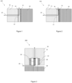
- the aerosol-generating device 100 shown in Figures 1 and 2 comprises a storage container 10 containing a supply of a liquid aerosol-forming substrate, the storage container 10 having an outlet 12. Further, the device 100 comprises a heating element 14 longitudinally spaced from the storage container 10. The heating element 14 is adapted to vaporise the liquid aerosol-forming substrate to form an inhalable aerosol.
- the aerosol-generating device 100 further comprises a transfer element 16 located between the storage container 10 and the heating element 14.
- the transfer element 16 is adapted to receive and retain liquid aerosol-forming substrate 11 from the storage container 10 and capable of being operatively coupled with the heating element 14 to supply the liquid aerosol-forming substrate received from the storage container 10 to the heating element 14.
- a liquid supply path can be identified that extends from the outlet 12 of the storage container 10 to the heating element 14.
- the transfer element 16 is downstream of the storage container 10 and upstream of the heating element 14.
- the transfer element 16 is adapted to receive and retain a predetermined amount of liquid aerosol-forming substrate, namely about 3 microlitres, from the storage container 10 and capable of supplying such received predetermined amount of liquid aerosol-forming substrate to the heating element 14 when operatively coupled with the heating element 14.
- the transfer element 16 is movable between a loading position (as shown in Figure 1 ) and a heating position (seen in Figure 2 ).
- the aerosol-generating device of Figures 1 and 2 is configured such that: when the transfer element 16 is in the loading position, the transfer element 16 is in fluid communication with the outlet 12 of the storage container 10. When the transfer element 16 is in the heating position, the transfer element 16 is in fluid communication with the heating element 14 and the heating element is activated to vaporise liquid aerosol-forming substrate retained in the transfer element 16.
- the aerosol-generating device of Figures 1 and 2 further comprises electronics 18 comprising a power supply and a controller, and an actuator (not shown) for moving the transfer element 16 between the storage container 10 and the heating element 14 along the liquid supply path.
- the controller is configured to monitor air flow at a location in the device 100 based on detection of a change in air flow indicative of a user inhalation (indicated schematically by the arrow in Figures 1 and 2 ); to power the actuator such that the transfer element 16 moves on its own from the loading position to the heating position; to supply a predetermined amount of power to the heating element 14, the predetermined amount of power being sufficient for the heating element to vaporise the liquid aerosol-forming substrate retained in the transfer element 16.
- Reference numeral 200 in Figure 3 identifies another embodiment of an aerosol-generating device in accordance with the present invention.
- the device 200 differs from the device 100 for the spatial arrangement of the various components of the device.
- the transfer element 16 and the heating element 14 are substantially concentrically arranged, and a radial distance between the transfer element 16 and the heating element 14 in the loading position is different from a radial distance between the transfer element 16 and the heating element 14 in the heating position.
- the same numerals will be used in the following description to identify components of the device 200 corresponding structurally and functionally to the components of the device 100.
- the aerosol-generating device 200 comprises a storage container 10 containing a supply of a liquid aerosol-forming substrate, the storage container 10 having two outlets 12. As seen in Figures 4 and 5 , the storage container 10 has an annular cross-section. Further, the device 200 comprises a heating element 14 arranged centrally and radially spaced from the outlets 12 of the storage container 10. The heating element 14 is adapted to vaporise the liquid aerosol-forming substrate to form an inhalable aerosol.
- the aerosol-generating device 200 further comprises a pair of transfer elements 16 located at a radially intermediate position between the storage container 10 and the heating element 14.
- the transfer elements 16 are adapted to receive and retain liquid aerosol-forming substrate from the storage container 10 and capable of being operatively coupled with the heating element 14 to supply the liquid aerosol-forming substrate received from the storage container 10 to the heating element 14.
- both transfer elements 16 are movable between a loading position (as shown in Figure 4 ) and a heating position (seen in Figure 5 ).
- the aerosol-generating device of Figures 3-4-5 is configured such that: when the transfer elements 16 are in the loading position, the transfer elements 16 are in fluid communication with the outlets 12 of the storage container 10. When the transfer element 16 are in the heating position, the transfer elements 16 are in fluid communication with the heating element 14 and the heating element is activated to vaporise liquid aerosol-forming substrate retained in the transfer elements 16.
Claims (12)
- Dispositif de génération d'aérosol (100 ; 200) comprenant :un récipient de stockage (10) contenant une alimentation d'un substrat formant aérosol liquide, le récipient de stockage ayant une sortie (12) ;un élément de chauffage (14) espacé du récipient de stockage (10), l'élément de chauffage (14) étant adapté à la vaporisation du substrat formant aérosol liquide pour former un aérosol inhalable ;un élément de transfert (16) situé entre le récipient de stockage (10) et l'élément de chauffage (14), l'élément de transfert (16) étant adapté à la réception et à la retenue du substrat formant aérosol liquide depuis le récipient de stockage (10) et pouvant être couplé de manière opérationnelle à l'élément de chauffage (14) pour alimenter le substrat formant aérosol liquide reçu vers l'élément de chauffage (14) ;dans lequel l'élément de transfert (16) est mobile seul le long d'un trajet d'alimentation en liquide entre une position de chargement et une position de chauffage, l'élément de transfert (16) étant mobile indépendamment du récipient de stockage (10), de sorte que, lorsque l'élément de transfert (16) se déplace entre la position de chargement et la position de chauffage, le récipient de stockage (10) ne se déplace pas avec l'élément de transfert (16) ;dans lequel le dispositif de génération d'aérosol est configuré de telle sorte que :lorsque l'élément de transfert (16) est dans la position de chargement, l'élément de transfert (16) est en communication fluidique avec la sortie (12) du récipient de stockage (10) ou avec la sortie (12) du récipient de stockage (10) et avec l'élément de chauffage (14) ; et lorsque l'élément de transfert (16) est dans la position de chauffage, l'élément de transfert (16) est en communication fluidique avec l'élément de chauffage (14) et l'élément de chauffage (14) est activé pour vaporiser le substrat formant aérosol liquide retenu dans l'élément de transfert (16) ;dans lequel l'élément de transfert (16) et l'élément de chauffage (14) sont alignés longitudinalement et une distance longitudinale entre l'élément de transfert (16) et l'élément de chauffage (14) dans la position de chargement est supérieure à une distance longitudinale entre l'élément de transfert (16) et l'élément de chauffage (14) dans la position de chauffage ; oudans lequel l'élément de transfert (16) et l'élément de chauffage (14) sont agencés de manière sensiblement concentrique et une distance radiale entre l'élément de transfert (16) et l'élément de chauffage (14) dans la position de chargement est supérieure à une distance radiale entre l'élément de transfert (16) et l'élément de chauffage (14) dans la position de chauffage.
- Dispositif selon la revendication 1, dans lequel l'élément de transfert (16) est mobile entre le récipient de stockage (10) et l'élément de chauffage (14), le dispositif étant configuré de telle sorte que, lorsque l'élément de transfert (16) est dans la position de chauffage, l'élément de transfert (16) est couplé de manière opérationnelle avec l'élément de chauffage (14) et le substrat formant aérosol liquide retenu dans l'élément de transfert (16) est alimenté vers l'élément de chauffage (14).
- Dispositif selon la revendication 2 comprenant en outre :une alimentation électrique ;un dispositif de commande ; etun actionneur destiné à déplacer l'élément de transfert (16) le long du trajet d'alimentation en liquide ;dans lequel le dispositif de commande est configuré pour :
surveiller l'écoulement d'air à un emplacement dans le dispositif sur la base de la détection d'un changement dans l'écoulement d'air indiquant une inhalation d'un utilisateur :fournir de la puissance à l'actionneur de sorte que l'élément de transfert (16) se déplace de la position de chargement à la position de chauffage ;fournir de la puissance à l'élément de chauffage (14) pour vaporiser le substrat formant aérosol liquide retenu dans l'élément de transfert (16). - Dispositif selon la revendication 3, dans lequel le dispositif de commande est configuré pour fournir de la puissance à l'actionneur de telle sorte que l'élément de transfert (16) revient de la position de chauffage à la position de chargement après une durée prédéterminée (THP).
- Dispositif selon la revendication 3, dans lequel le dispositif de commande est configuré pour fournir de la puissance à l'actionneur de telle sorte que l'élément de transfert (16) revient de la position de chauffage à la position de chargement sur la base de la détection d'un changement dans l'écoulement d'air à un emplacement dans le dispositif indicatif de la fin d'une inhalation d'un utilisateur.
- Dispositif selon l'une quelconque des revendications 1 à 5, dans lequel l'élément de transfert (16) comprend une première surface d'extrémité et une deuxième surface d'extrémité distale par rapport à la première surface d'extrémité, la première surface d'extrémité faisant face au récipient de stockage (10) lorsque l'au moins un parmi l'élément de transfert (16) et l'élément de chauffage (14) est dans la position de chargement.
- Dispositif selon la revendication 6, dans lequel le dispositif est configuré de telle sorte que, lorsque l'élément de transfert (16) est dans la position de chargement, la première surface d'extrémité de l'élément de transfert (16) fait face à l'élément de chauffage (14).
- Dispositif selon la revendication 6, dans lequel l'élément de transfert (16) comprend au moins un conduit traversant s'étendant de la première surface d'extrémité à la deuxième surface d'extrémité, et dans lequel le dispositif est configuré de telle sorte que, lorsque l'élément de transfert (16) est dans la position de chargement, la deuxième surface d'extrémité de l'élément de transfert (16) fait face à l'élément de chauffage.
- Dispositif selon l'une quelconque des revendications précédentes, comprenant un dispositif de commande raccordé à au moins l'un parmi l'élément de transfert (16) et l'élément de chauffage (14), dans lequel le dispositif de commande est configuré pour surveiller les changements d'une propriété électrique de l'au moins l'un parmi l'élément de transfert (16) et l'élément de chauffage (14) indiquant un changement de la quantité de substrat formant aérosol liquide porté par l'au moins l'un parmi l'élément de transfert (16) et l'élément de chauffage (14).
- Dispositif selon l'une quelconque des revendications précédentes, dans lequel au moins l'un parmi l'élément de chauffage (14) et l'élément de transfert (16) est perméable au fluide.
- Dispositif selon l'une quelconque des revendications précédentes, dans lequel l'élément de transfert (16) est adapté à la réception et à la retenue d'une quantité prédéterminée de substrat formant aérosol liquide à partir du récipient de stockage (10) et est capable d'alimenter la quantité prédéterminée reçue de substrat formant aérosol liquide à l'élément de chauffage (14) lorsqu'il est couplé de manière opérationnelle à l'élément de chauffage (14).
- Dispositif selon la revendication 11, dans lequel la quantité prédéterminée de substrat formant aérosol liquide est d'au moins environ 3 microlitres.
Applications Claiming Priority (2)
| Application Number | Priority Date | Filing Date | Title |
|---|---|---|---|
| EP18176362 | 2018-06-06 | ||
| PCT/EP2019/064884 WO2019234195A1 (fr) | 2018-06-06 | 2019-06-06 | Dispositif de production d'aérosol ayant un composant mobile pour transférer un substrat formant un aérosol |
Publications (2)
| Publication Number | Publication Date |
|---|---|
| EP3801089A1 EP3801089A1 (fr) | 2021-04-14 |
| EP3801089B1 true EP3801089B1 (fr) | 2023-03-22 |
Family
ID=62563022
Family Applications (1)
| Application Number | Title | Priority Date | Filing Date |
|---|---|---|---|
| EP19728703.0A Active EP3801089B1 (fr) | 2018-06-06 | 2019-06-06 | Dispositif de génération d'aérosol ayant un composant mobile de transfert de substrat de formation d'aérosol |
Country Status (9)
| Country | Link |
|---|---|
| US (1) | US11871786B2 (fr) |
| EP (1) | EP3801089B1 (fr) |
| KR (1) | KR20210018805A (fr) |
| CN (1) | CN112118752B (fr) |
| BR (1) | BR112020022570A2 (fr) |
| IL (1) | IL278792B1 (fr) |
| PH (1) | PH12020552016A1 (fr) |
| PL (1) | PL3801089T3 (fr) |
| WO (1) | WO2019234195A1 (fr) |
Families Citing this family (4)
| Publication number | Priority date | Publication date | Assignee | Title |
|---|---|---|---|---|
| AU2014381785B2 (en) * | 2014-02-10 | 2019-03-14 | Philip Morris Products S.A. | Fluid permeable heater assembly for an aerosol-generating system and method for assembling a fluid permeable heater for an aerosol-generating system |
| KR20210016361A (ko) * | 2018-05-31 | 2021-02-15 | 필립모리스 프로덕츠 에스.에이. | 천공된 이송 물질을 구비한 히터 조립체 |
| EP4151099A4 (fr) * | 2020-05-12 | 2023-08-09 | Shenzhen Smoore Technology Limited | Dispositif d'atomisation |
| EP4101322A1 (fr) * | 2021-06-08 | 2022-12-14 | JT International SA | Dispositif de génération de vapeur, unité de vaporisateur associée et procédé de commande de génération de vapeur |
Family Cites Families (12)
| Publication number | Priority date | Publication date | Assignee | Title |
|---|---|---|---|---|
| US5269327A (en) * | 1989-12-01 | 1993-12-14 | Philip Morris Incorporated | Electrical smoking article |
| US7234470B2 (en) | 2003-08-28 | 2007-06-26 | Philip Morris Usa Inc. | Electromagnetic mechanism for positioning heater blades of an electrically heated cigarette smoking system |
| UA114898C2 (uk) | 2011-10-27 | 2017-08-28 | Філіп Морріс Продактс С.А. | Система утворення аерозолю з вдосконаленим утворенням аерозолю |
| UA112883C2 (uk) | 2011-12-08 | 2016-11-10 | Філіп Морріс Продактс С.А. | Пристрій для утворення аерозолю з капілярним примежовим шаром |
| ES2661023T3 (es) | 2011-12-08 | 2018-03-27 | Philip Morris Products S.A. | Dispositivo generador de aerosol con flujo de aire ajustable |
| US8881737B2 (en) | 2012-09-04 | 2014-11-11 | R.J. Reynolds Tobacco Company | Electronic smoking article comprising one or more microheaters |
| US9918496B2 (en) * | 2013-07-24 | 2018-03-20 | Altria Client Services Llc | Electronic smoking article |
| WO2015086316A1 (fr) * | 2013-12-11 | 2015-06-18 | Jt International S.A. | Système de chauffage et procédé pour chauffer un dispositif d'inhalateur |
| GB201410171D0 (en) | 2014-06-09 | 2014-07-23 | Nicoventures Holdings Ltd | Electronic vapour provision system |
| JP6783764B2 (ja) * | 2014-12-15 | 2020-11-11 | フィリップ・モーリス・プロダクツ・ソシエテ・アノニム | エアロゾル発生装置 |
| EP3273815B1 (fr) | 2015-03-27 | 2021-11-03 | Philip Morris Products S.A. | Système de génération d'aérosol comprenant un bilame |
| KR102602870B1 (ko) | 2017-02-24 | 2023-11-16 | 필립모리스 프로덕츠 에스.에이. | 에어로졸 발생 시스템 내 에어로졸 발생 요소를 위한 성형된 장착 |
-
2019
- 2019-06-06 KR KR1020207033458A patent/KR20210018805A/ko unknown
- 2019-06-06 EP EP19728703.0A patent/EP3801089B1/fr active Active
- 2019-06-06 PL PL19728703.0T patent/PL3801089T3/pl unknown
- 2019-06-06 CN CN201980032184.0A patent/CN112118752B/zh active Active
- 2019-06-06 BR BR112020022570-3A patent/BR112020022570A2/pt unknown
- 2019-06-06 WO PCT/EP2019/064884 patent/WO2019234195A1/fr active Search and Examination
- 2019-06-06 IL IL278792A patent/IL278792B1/en unknown
- 2019-06-06 US US16/972,183 patent/US11871786B2/en active Active
-
2020
- 2020-11-23 PH PH12020552016A patent/PH12020552016A1/en unknown
Also Published As
| Publication number | Publication date |
|---|---|
| KR20210018805A (ko) | 2021-02-18 |
| PH12020552016A1 (en) | 2021-06-14 |
| WO2019234195A1 (fr) | 2019-12-12 |
| IL278792B1 (en) | 2024-01-01 |
| PL3801089T3 (pl) | 2023-06-05 |
| EP3801089A1 (fr) | 2021-04-14 |
| US11871786B2 (en) | 2024-01-16 |
| JP2021526364A (ja) | 2021-10-07 |
| IL278792A (en) | 2021-01-31 |
| CN112118752B (zh) | 2024-04-02 |
| US20210235759A1 (en) | 2021-08-05 |
| CN112118752A (zh) | 2020-12-22 |
| BR112020022570A2 (pt) | 2021-02-02 |
Similar Documents
| Publication | Publication Date | Title |
|---|---|---|
| EP3801089B1 (fr) | Dispositif de génération d'aérosol ayant un composant mobile de transfert de substrat de formation d'aérosol | |
| EP3232840B1 (fr) | Systèmes et procédés de génération d'aérosol pour guider un flux d'air à l'intérieur d'un système de génération d'aérosol chauffé électriquement | |
| KR102045233B1 (ko) | 응축물 누설을 방지하는 에어로졸 발생 시스템 | |
| RU2747612C2 (ru) | Система, генерирующая аэрозоль, содержащая несколько субстратов, образующих аэрозоль | |
| TWI589235B (zh) | 具可調氣流之氣溶膠產生裝置 | |
| RU2756803C2 (ru) | Система, генерирующая аэрозоль, содержащая несколько субстратов, образующих аэрозоль, и прокалывающий элемент | |
| UA119761C2 (uk) | Картридж для генеруючої аерозоль системи | |
| CN113286527B (zh) | 雾化器和包括雾化器的气溶胶生成系统 | |
| CN113015448A (zh) | 气溶胶生成系统和具有泄漏保护的筒 | |
| JP2024023409A (ja) | ニコチンの優先的な蒸発を提供するエアロゾル発生システム | |
| RU2792800C2 (ru) | Устройство, генерирующее аэрозоль, имеющее подвижный компонент для перемещения субстрата, образующего аэрозоль | |
| JP7485614B2 (ja) | エアロゾル形成基体を移動するための移動可能な構成要素を有するエアロゾル発生装置 | |
| RU2789880C2 (ru) | Устройство для генерирования аэрозоля и способ генерирования никотин содержащего аэрозоля | |
| RU2814485C2 (ru) | Система, генерирующая аэрозоль, и картридж с защитой от утечки | |
| RU2775496C2 (ru) | Генерирующее аэрозоль устройство с уменьшенной утечкой | |
| RU2783933C2 (ru) | Нагреватель в сборе, имеющий нагревательный элемент, изолированный от запаса жидкости |
Legal Events
| Date | Code | Title | Description |
|---|---|---|---|
| STAA | Information on the status of an ep patent application or granted ep patent |
Free format text: STATUS: UNKNOWN |
|
| STAA | Information on the status of an ep patent application or granted ep patent |
Free format text: STATUS: THE INTERNATIONAL PUBLICATION HAS BEEN MADE |
|
| STAA | Information on the status of an ep patent application or granted ep patent |
Free format text: STATUS: THE INTERNATIONAL PUBLICATION HAS BEEN MADE |
|
| PUAI | Public reference made under article 153(3) epc to a published international application that has entered the european phase |
Free format text: ORIGINAL CODE: 0009012 |
|
| STAA | Information on the status of an ep patent application or granted ep patent |
Free format text: STATUS: REQUEST FOR EXAMINATION WAS MADE |
|
| 17P | Request for examination filed |
Effective date: 20201202 |
|
| AK | Designated contracting states |
Kind code of ref document: A1 Designated state(s): AL AT BE BG CH CY CZ DE DK EE ES FI FR GB GR HR HU IE IS IT LI LT LU LV MC MK MT NL NO PL PT RO RS SE SI SK SM TR |
|
| AX | Request for extension of the european patent |
Extension state: BA ME |
|
| DAV | Request for validation of the european patent (deleted) | ||
| DAX | Request for extension of the european patent (deleted) | ||
| REG | Reference to a national code |
Ref country code: DE Ref legal event code: R079 Ref document number: 602019026664 Country of ref document: DE Free format text: PREVIOUS MAIN CLASS: A24F0047000000 Ipc: A24F0040440000 |
|
| RIC1 | Information provided on ipc code assigned before grant |
Ipc: A24F 40/10 20200101ALN20220806BHEP Ipc: A24F 40/44 20200101AFI20220806BHEP |
|
| GRAP | Despatch of communication of intention to grant a patent |
Free format text: ORIGINAL CODE: EPIDOSNIGR1 |
|
| STAA | Information on the status of an ep patent application or granted ep patent |
Free format text: STATUS: GRANT OF PATENT IS INTENDED |
|
| RIC1 | Information provided on ipc code assigned before grant |
Ipc: A24F 40/10 20200101ALN20220907BHEP Ipc: A24F 40/44 20200101AFI20220907BHEP |
|
| INTG | Intention to grant announced |
Effective date: 20221012 |
|
| GRAS | Grant fee paid |
Free format text: ORIGINAL CODE: EPIDOSNIGR3 |
|
| GRAA | (expected) grant |
Free format text: ORIGINAL CODE: 0009210 |
|
| STAA | Information on the status of an ep patent application or granted ep patent |
Free format text: STATUS: THE PATENT HAS BEEN GRANTED |
|
| AK | Designated contracting states |
Kind code of ref document: B1 Designated state(s): AL AT BE BG CH CY CZ DE DK EE ES FI FR GB GR HR HU IE IS IT LI LT LU LV MC MK MT NL NO PL PT RO RS SE SI SK SM TR |
|
| REG | Reference to a national code |
Ref country code: GB Ref legal event code: FG4D |
|
| REG | Reference to a national code |
Ref country code: CH Ref legal event code: EP |
|
| REG | Reference to a national code |
Ref country code: IE Ref legal event code: FG4D |
|
| REG | Reference to a national code |
Ref country code: DE Ref legal event code: R096 Ref document number: 602019026664 Country of ref document: DE |
|
| REG | Reference to a national code |
Ref country code: AT Ref legal event code: REF Ref document number: 1554746 Country of ref document: AT Kind code of ref document: T Effective date: 20230415 |
|
| REG | Reference to a national code |
Ref country code: RO Ref legal event code: EPE |
|
| REG | Reference to a national code |
Ref country code: NL Ref legal event code: FP |
|
| REG | Reference to a national code |
Ref country code: LT Ref legal event code: MG9D |
|
| P01 | Opt-out of the competence of the unified patent court (upc) registered |
Effective date: 20230529 |
|
| PG25 | Lapsed in a contracting state [announced via postgrant information from national office to epo] |
Ref country code: RS Free format text: LAPSE BECAUSE OF FAILURE TO SUBMIT A TRANSLATION OF THE DESCRIPTION OR TO PAY THE FEE WITHIN THE PRESCRIBED TIME-LIMIT Effective date: 20230322 Ref country code: NO Free format text: LAPSE BECAUSE OF FAILURE TO SUBMIT A TRANSLATION OF THE DESCRIPTION OR TO PAY THE FEE WITHIN THE PRESCRIBED TIME-LIMIT Effective date: 20230622 Ref country code: LV Free format text: LAPSE BECAUSE OF FAILURE TO SUBMIT A TRANSLATION OF THE DESCRIPTION OR TO PAY THE FEE WITHIN THE PRESCRIBED TIME-LIMIT Effective date: 20230322 Ref country code: LT Free format text: LAPSE BECAUSE OF FAILURE TO SUBMIT A TRANSLATION OF THE DESCRIPTION OR TO PAY THE FEE WITHIN THE PRESCRIBED TIME-LIMIT Effective date: 20230322 Ref country code: HR Free format text: LAPSE BECAUSE OF FAILURE TO SUBMIT A TRANSLATION OF THE DESCRIPTION OR TO PAY THE FEE WITHIN THE PRESCRIBED TIME-LIMIT Effective date: 20230322 |
|
| PGFP | Annual fee paid to national office [announced via postgrant information from national office to epo] |
Ref country code: RO Payment date: 20230608 Year of fee payment: 5 Ref country code: NL Payment date: 20230620 Year of fee payment: 5 Ref country code: FR Payment date: 20230628 Year of fee payment: 5 Ref country code: DE Payment date: 20230620 Year of fee payment: 5 |
|
| REG | Reference to a national code |
Ref country code: AT Ref legal event code: MK05 Ref document number: 1554746 Country of ref document: AT Kind code of ref document: T Effective date: 20230322 |
|
| PG25 | Lapsed in a contracting state [announced via postgrant information from national office to epo] |
Ref country code: SE Free format text: LAPSE BECAUSE OF FAILURE TO SUBMIT A TRANSLATION OF THE DESCRIPTION OR TO PAY THE FEE WITHIN THE PRESCRIBED TIME-LIMIT Effective date: 20230322 Ref country code: GR Free format text: LAPSE BECAUSE OF FAILURE TO SUBMIT A TRANSLATION OF THE DESCRIPTION OR TO PAY THE FEE WITHIN THE PRESCRIBED TIME-LIMIT Effective date: 20230623 Ref country code: FI Free format text: LAPSE BECAUSE OF FAILURE TO SUBMIT A TRANSLATION OF THE DESCRIPTION OR TO PAY THE FEE WITHIN THE PRESCRIBED TIME-LIMIT Effective date: 20230322 |
|
| PGFP | Annual fee paid to national office [announced via postgrant information from national office to epo] |
Ref country code: PL Payment date: 20230605 Year of fee payment: 5 |
|
| PG25 | Lapsed in a contracting state [announced via postgrant information from national office to epo] |
Ref country code: SM Free format text: LAPSE BECAUSE OF FAILURE TO SUBMIT A TRANSLATION OF THE DESCRIPTION OR TO PAY THE FEE WITHIN THE PRESCRIBED TIME-LIMIT Effective date: 20230322 Ref country code: PT Free format text: LAPSE BECAUSE OF FAILURE TO SUBMIT A TRANSLATION OF THE DESCRIPTION OR TO PAY THE FEE WITHIN THE PRESCRIBED TIME-LIMIT Effective date: 20230724 Ref country code: ES Free format text: LAPSE BECAUSE OF FAILURE TO SUBMIT A TRANSLATION OF THE DESCRIPTION OR TO PAY THE FEE WITHIN THE PRESCRIBED TIME-LIMIT Effective date: 20230322 Ref country code: EE Free format text: LAPSE BECAUSE OF FAILURE TO SUBMIT A TRANSLATION OF THE DESCRIPTION OR TO PAY THE FEE WITHIN THE PRESCRIBED TIME-LIMIT Effective date: 20230322 Ref country code: AT Free format text: LAPSE BECAUSE OF FAILURE TO SUBMIT A TRANSLATION OF THE DESCRIPTION OR TO PAY THE FEE WITHIN THE PRESCRIBED TIME-LIMIT Effective date: 20230322 |
|
| PGFP | Annual fee paid to national office [announced via postgrant information from national office to epo] |
Ref country code: IT Payment date: 20230718 Year of fee payment: 5 Ref country code: GB Payment date: 20230622 Year of fee payment: 5 Ref country code: CH Payment date: 20230702 Year of fee payment: 5 |
|
| PG25 | Lapsed in a contracting state [announced via postgrant information from national office to epo] |
Ref country code: SK Free format text: LAPSE BECAUSE OF FAILURE TO SUBMIT A TRANSLATION OF THE DESCRIPTION OR TO PAY THE FEE WITHIN THE PRESCRIBED TIME-LIMIT Effective date: 20230322 Ref country code: IS Free format text: LAPSE BECAUSE OF FAILURE TO SUBMIT A TRANSLATION OF THE DESCRIPTION OR TO PAY THE FEE WITHIN THE PRESCRIBED TIME-LIMIT Effective date: 20230722 |
|
| REG | Reference to a national code |
Ref country code: DE Ref legal event code: R097 Ref document number: 602019026664 Country of ref document: DE |
|
| PG25 | Lapsed in a contracting state [announced via postgrant information from national office to epo] |
Ref country code: MC Free format text: LAPSE BECAUSE OF FAILURE TO SUBMIT A TRANSLATION OF THE DESCRIPTION OR TO PAY THE FEE WITHIN THE PRESCRIBED TIME-LIMIT Effective date: 20230322 |
|
| PLBE | No opposition filed within time limit |
Free format text: ORIGINAL CODE: 0009261 |
|
| STAA | Information on the status of an ep patent application or granted ep patent |
Free format text: STATUS: NO OPPOSITION FILED WITHIN TIME LIMIT |
|
| PG25 | Lapsed in a contracting state [announced via postgrant information from national office to epo] |
Ref country code: SI Free format text: LAPSE BECAUSE OF FAILURE TO SUBMIT A TRANSLATION OF THE DESCRIPTION OR TO PAY THE FEE WITHIN THE PRESCRIBED TIME-LIMIT Effective date: 20230322 Ref country code: MC Free format text: LAPSE BECAUSE OF FAILURE TO SUBMIT A TRANSLATION OF THE DESCRIPTION OR TO PAY THE FEE WITHIN THE PRESCRIBED TIME-LIMIT Effective date: 20230322 Ref country code: DK Free format text: LAPSE BECAUSE OF FAILURE TO SUBMIT A TRANSLATION OF THE DESCRIPTION OR TO PAY THE FEE WITHIN THE PRESCRIBED TIME-LIMIT Effective date: 20230322 Ref country code: CZ Free format text: LAPSE BECAUSE OF FAILURE TO SUBMIT A TRANSLATION OF THE DESCRIPTION OR TO PAY THE FEE WITHIN THE PRESCRIBED TIME-LIMIT Effective date: 20230322 |
|
| REG | Reference to a national code |
Ref country code: BE Ref legal event code: MM Effective date: 20230630 |
|
| 26N | No opposition filed |
Effective date: 20240102 |
|
| PG25 | Lapsed in a contracting state [announced via postgrant information from national office to epo] |
Ref country code: LU Free format text: LAPSE BECAUSE OF NON-PAYMENT OF DUE FEES Effective date: 20230606 |
|
| REG | Reference to a national code |
Ref country code: IE Ref legal event code: MM4A |
|
| PG25 | Lapsed in a contracting state [announced via postgrant information from national office to epo] |
Ref country code: LU Free format text: LAPSE BECAUSE OF NON-PAYMENT OF DUE FEES Effective date: 20230606 |
|
| PG25 | Lapsed in a contracting state [announced via postgrant information from national office to epo] |
Ref country code: IE Free format text: LAPSE BECAUSE OF NON-PAYMENT OF DUE FEES Effective date: 20230606 |
|
| PG25 | Lapsed in a contracting state [announced via postgrant information from national office to epo] |
Ref country code: IE Free format text: LAPSE BECAUSE OF NON-PAYMENT OF DUE FEES Effective date: 20230606 |