EP3800980B1 - Autorollenhöhe - Google Patents
Autorollenhöhe Download PDFInfo
- Publication number
- EP3800980B1 EP3800980B1 EP19737875.5A EP19737875A EP3800980B1 EP 3800980 B1 EP3800980 B1 EP 3800980B1 EP 19737875 A EP19737875 A EP 19737875A EP 3800980 B1 EP3800980 B1 EP 3800980B1
- Authority
- EP
- European Patent Office
- Prior art keywords
- reel
- height
- load
- crop
- header
- Prior art date
- Legal status (The legal status is an assumption and is not a legal conclusion. Google has not performed a legal analysis and makes no representation as to the accuracy of the status listed.)
- Active
Links
- 230000008859 change Effects 0.000 claims description 23
- 238000000034 method Methods 0.000 claims description 22
- 238000005259 measurement Methods 0.000 claims description 7
- 238000003384 imaging method Methods 0.000 description 28
- 238000010586 diagram Methods 0.000 description 15
- 230000007246 mechanism Effects 0.000 description 15
- 238000004422 calculation algorithm Methods 0.000 description 10
- 238000001514 detection method Methods 0.000 description 10
- 238000012545 processing Methods 0.000 description 10
- 238000004891 communication Methods 0.000 description 9
- 230000006870 function Effects 0.000 description 9
- 230000003287 optical effect Effects 0.000 description 9
- 238000005516 engineering process Methods 0.000 description 7
- 239000012530 fluid Substances 0.000 description 7
- 230000008901 benefit Effects 0.000 description 6
- 238000003306 harvesting Methods 0.000 description 5
- 239000000463 material Substances 0.000 description 5
- 230000008569 process Effects 0.000 description 5
- 238000003860 storage Methods 0.000 description 5
- 238000006073 displacement reaction Methods 0.000 description 4
- 230000011664 signaling Effects 0.000 description 4
- 230000000694 effects Effects 0.000 description 3
- 238000009313 farming Methods 0.000 description 3
- 235000015097 nutrients Nutrition 0.000 description 3
- 230000005855 radiation Effects 0.000 description 3
- 238000002835 absorbance Methods 0.000 description 2
- 230000005540 biological transmission Effects 0.000 description 2
- 238000004364 calculation method Methods 0.000 description 2
- 230000001413 cellular effect Effects 0.000 description 2
- 238000013479 data entry Methods 0.000 description 2
- 238000013461 design Methods 0.000 description 2
- 230000002085 persistent effect Effects 0.000 description 2
- 239000004065 semiconductor Substances 0.000 description 2
- 238000001228 spectrum Methods 0.000 description 2
- 239000013589 supplement Substances 0.000 description 2
- 238000001429 visible spectrum Methods 0.000 description 2
- 235000014698 Brassica juncea var multisecta Nutrition 0.000 description 1
- 235000006008 Brassica napus var napus Nutrition 0.000 description 1
- 240000000385 Brassica napus var. napus Species 0.000 description 1
- 235000006618 Brassica rapa subsp oleifera Nutrition 0.000 description 1
- 235000004977 Brassica sinapistrum Nutrition 0.000 description 1
- 241000196324 Embryophyta Species 0.000 description 1
- 230000005355 Hall effect Effects 0.000 description 1
- 238000010521 absorption reaction Methods 0.000 description 1
- 238000013459 approach Methods 0.000 description 1
- 230000000712 assembly Effects 0.000 description 1
- 238000000429 assembly Methods 0.000 description 1
- 230000006399 behavior Effects 0.000 description 1
- 238000009530 blood pressure measurement Methods 0.000 description 1
- 238000002485 combustion reaction Methods 0.000 description 1
- 238000004590 computer program Methods 0.000 description 1
- 230000001143 conditioned effect Effects 0.000 description 1
- 230000003750 conditioning effect Effects 0.000 description 1
- 239000004020 conductor Substances 0.000 description 1
- 230000003247 decreasing effect Effects 0.000 description 1
- 230000001419 dependent effect Effects 0.000 description 1
- 238000001035 drying Methods 0.000 description 1
- 230000009977 dual effect Effects 0.000 description 1
- 230000005672 electromagnetic field Effects 0.000 description 1
- 230000004907 flux Effects 0.000 description 1
- 230000004927 fusion Effects 0.000 description 1
- 230000010354 integration Effects 0.000 description 1
- 230000003993 interaction Effects 0.000 description 1
- 230000009347 mechanical transmission Effects 0.000 description 1
- 239000002184 metal Substances 0.000 description 1
- 238000012986 modification Methods 0.000 description 1
- 230000004048 modification Effects 0.000 description 1
- 230000001105 regulatory effect Effects 0.000 description 1
- 238000009877 rendering Methods 0.000 description 1
- 238000010408 sweeping Methods 0.000 description 1
- 230000000007 visual effect Effects 0.000 description 1
Images


Classifications
-
- A—HUMAN NECESSITIES
- A01—AGRICULTURE; FORESTRY; ANIMAL HUSBANDRY; HUNTING; TRAPPING; FISHING
- A01D—HARVESTING; MOWING
- A01D57/00—Delivering mechanisms for harvesters or mowers
- A01D57/01—Devices for leading crops to the mowing apparatus
- A01D57/02—Devices for leading crops to the mowing apparatus using reels
- A01D57/04—Arrangements for changing the position of the reels
-
- A—HUMAN NECESSITIES
- A01—AGRICULTURE; FORESTRY; ANIMAL HUSBANDRY; HUNTING; TRAPPING; FISHING
- A01D—HARVESTING; MOWING
- A01D34/00—Mowers; Mowing apparatus of harvesters
- A01D34/01—Mowers; Mowing apparatus of harvesters characterised by features relating to the type of cutting apparatus
- A01D34/02—Mowers; Mowing apparatus of harvesters characterised by features relating to the type of cutting apparatus having reciprocating cutters
- A01D34/28—Adjusting devices for the cutter-bar
- A01D34/283—Adjustment of the cutter bar in a vertical plane, i.e. to adjust the angle between the cutter bar and the soil
-
- A—HUMAN NECESSITIES
- A01—AGRICULTURE; FORESTRY; ANIMAL HUSBANDRY; HUNTING; TRAPPING; FISHING
- A01D—HARVESTING; MOWING
- A01D57/00—Delivering mechanisms for harvesters or mowers
- A01D57/01—Devices for leading crops to the mowing apparatus
- A01D57/02—Devices for leading crops to the mowing apparatus using reels
-
- A—HUMAN NECESSITIES
- A01—AGRICULTURE; FORESTRY; ANIMAL HUSBANDRY; HUNTING; TRAPPING; FISHING
- A01D—HARVESTING; MOWING
- A01D61/00—Elevators or conveyors for binders or combines
- A01D61/002—Elevators or conveyors for binders or combines transversal conveying devices
- A01D61/004—Elevators or conveyors for binders or combines transversal conveying devices with cylindrical tools
-
- A—HUMAN NECESSITIES
- A01—AGRICULTURE; FORESTRY; ANIMAL HUSBANDRY; HUNTING; TRAPPING; FISHING
- A01D—HARVESTING; MOWING
- A01D61/00—Elevators or conveyors for binders or combines
- A01D61/02—Endless belts
Definitions
- the present disclosure is generally related to agricultural machines and, more particularly, control of implement function for implements operatively coupled to agricultural machines.
- EP2681984A describes a harvester having a reel and a cutting platform trough, along with a sensing arrangement for determining a height of the reel and a crop flux through the harvester.
- a computer-controlled method for adjusting a height of a header reel comprising: measuring a rotational speed of the reel; measuring a force opposing rotation of the reel; determining a target load for the reel based on the measured rotational speed and the measured force and a first input; and causing movement of the reel according to the target load based on a change in load on the reel.
- reel height adjustment system and method that enable closed-loop control of reel height with reel speed to maintain a consistent or near consistent feed of the harvested crop.
- reel speed is measured from a sensor and drive pressure is measured and adjusted to maintain the speed at a desired setpoint (either fixed or varying with forward velocity) to ensure a consistent or near consistent feed of the harvested crop into the machine.
- a desired setpoint either fixed or varying with forward velocity
- the speed is compared to a table of expected values for the output. Higher loads require more pressure to create the same speed.
- a load target load is derived based on the measured pressure and speed, and used to adjust the reel height.
- the reel height is adjusted until it reaches or approximates the target load. In some embodiments, the reel height is adjusted until it falls within a load window as specified by upper and lower setpoints. Note that the adjustment does not override the user adjustment of the reel height, but rather, adds to it.
- the automated mechanisms of certain embodiments of the reel height adjustment system may be paused whenever the user adjusts the height manually.
- the target load setpoint may be derived from either the last load (historical data) resulting from height and speed adjustment, or by numeric adjustment (e.g., an operator entering or selecting a value at a user interface).
- reel height adjustment, and/or adjustment of other header parameters may be based on electromagnetic-based crop feature detection (e.g., by sensing a change in electromagnetic fields based on interaction with the crop) in lieu of, or in addition to, the load-based determination explained above.
- one or more sensors may be mounted to the front of the header to create one or more beams of microwaves, light, infrared, or radiation from other ranges of the electromagnetic spectrum. The one or more beams are interrupted by the crop and gives an indication of the crop height and/or other crop features. This data can be used in addition to, or in place of, previously described rotational speed/load values-based determinations for adjustment of reel height and/or adjustments in other header and/or machine parameters.
- one or more sensors may be mounted to the front of the header to measure relative capacitance, radiative reflectance, or relative absorbance of radio waves, microwaves, light, infrared, or other forms of radiation.
- the comparison of values at different heights provides an indication of an approximate crop height.
- This data may also provide other or additional crop features, including crop moisture and/or nutrient data. This data can be used in addition to, or in place of, previously described reel height adjustment methods for adjusting one or more header and/or machine parameters.
- one or more cameras may be used with image processing and or machine learning software to determine one or more crop features, including crop height and/or contour of the crop. Such imaging may also be used for detecting field obstacles and/or crop type for prompting a change in other machine/header settings. For instance, detection of crop height/density changes may be used to infer headlands, where certain embodiments may responsively provide adjustments to reel height and/or reel speed. This data can be used in addition to, or in place of, previously described reel height adjustment methods.
- Automating reel height adjustment has the potential of reducing the amount of effort needed to operate a reel (e.g., of a draper or auger header) and/or other machine functions, and thus can reduce operator fatigue.
- Each method may have certain strengths that are used to advantage by the operator. For instance, time-of-flight (TOF) technology presents some challenges when observing crops that have significant variance in the height. In contrast, using image processing on single or multiple standard cameras may provide a much better representation of the effective crop height. Further, using load sensing has the advantage of being able to account for resistance that is not consistent with the height of the crop, but caused by other factors like crop growth direction, moisture, crop entanglement, etc.
- TOF time-of-flight
- balers use a reel as well, albeit in a different configuration than a windrower, where the pickup function may benefit from certain embodiments by having the ability to handle different windrow heights.
- certain embodiments of a reel height adjustment system may be used to influence other rotational mechanisms of the header, such as to control in similar manner a top auger to facilitate an improved feed of crop.
- the description identifies or describes specifics of one or more embodiments, such specifics are not necessarily part of every embodiment, nor are all of any various stated advantages necessarily associated with a single embodiment. On the contrary, the intent is to cover all alternatives, modifications and equivalents included within the principles and scope of the appended claims. Further, it should be appreciated in the context of the present disclosure that the claims are not necessarily limited to the particular embodiments set out in the description.
- FIG. 1 illustrates an example agricultural machine for which an embodiment of a reel height adjustment system may be implemented.
- the machine is depicted in FIG. 1 as a self-propelled windrower 10 with an auger header as an example implement attached thereto, though one having ordinary skill in the art should appreciate in the context of the present disclosure that other self-propelled, or pull-type, windrower designs with the same or different style headers (e.g., draper header), and/or other types of agricultural machines may be used with the same or different reel-equipped header, and hence are contemplated to be within the scope of the disclosure.
- style headers e.g., draper header
- the windrower 10 is generally operable to mow and collect standing crop in the field, condition the cut material to improve its drying characteristics, and then return the conditioned material to the field in a windrow or swath.
- the windrower 10 may include a chassis or frame 12 supported by wheels 14 (although tracks may be used in some embodiments, or other configurations in the number and/or arrangement of wheels may be used in some embodiments) for movement across a field to be harvested.
- the chassis 12 supports a cab 16, within which an operator may control certain operations of the windrower 10, and a rearwardly spaced compartment 18 housing a power source (not shown) such as an internal combustion engine.
- the chassis 12 also supports a ground drive system that, in one embodiment, when powered by the engine, causes differential rotation of the wheels (e.g., increasing the speed of one wheel while decreasing the speed of the opposite wheel) according to a dual path steering mechanism as is known in the art. In some embodiments, other mechanisms for enabling navigation and/or traversal of the field may be used.
- a coupled working implement depicted in FIG. 1 as a harvesting header 20 (e.g., auger header, though draper header may be used), is supported on the front of the chassis 12 in a manner understood by those skilled in the art.
- the header 20 may be configured as a modular unit and consequently may be disconnected for removal from the chassis 12.
- the header 20 has a laterally extending crop cutting assembly 22 in the form of a reciprocating sickle for severing standing crop from the ground, one or more rotating reels 24 for sweeping the standing crop into the sickle 22 to improve cutoff, and one or more conveyors (e.g., augers, slats, elastomeric endless belts, etc., not shown in FIG.
- the windrower 10 also comprises a computing system 26, which is coupled to a control system that monitors various parameters (e.g., pressure, speed) and/or crop features (crop height, density, contour, etc.) and provides for the adjustment of the height of the reel 24 (and/or other parameters, such as reel speed) based on the monitored parameters and/or features as explained further below.
- various parameters e.g., pressure, speed
- crop features crop height, density, contour, etc.
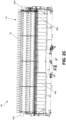
- FIGS. 2A-2C are schematic diagrams that illustrate various views of a header 28 (e.g., draper header) comprising a reel 30 that is adjusted in height by an embodiment of a reel height adjustment system.
- the header 28 may be used in place of the header 20 of FIG. 1
- the reel 30 may be used in place of the reel 24 of FIG. 1 .
- the header 28 comprises, in this example, a single reel 30 that extends transversely to the direction of forward travel of the windrower 10. In some embodiments, more than a single reel 30 may be used, wherein operation of each reel is either under independent control, or operation of all reels is under common control.
- the reel 30 comprises plural transverse rows of tines 32 that, upon rotation of the reel 30, pull crop toward an underlying, transverse crop cutting assembly 34 (see, e.g., FIG. 2A ) for performing severing actions on the crop.
- the crop cutting assembly 34 may be used in place of the crop cutting assembly 22 of FIG. 1 in some embodiments.
- the row of tines 32 moves toward the cutter 34 at a constant pace as the cutter 34 moves toward the crop, and in some embodiments, at a variable pace.
- the severed crop is drawn toward the center of the header 28 by plural conveyors 36A and 36B, beneath where the severed crop is dropped to the ground in a swath or windrow.
- the draper style header does not have shields or a conditioner, whereas auger-style headers may possess conditioner rolls, forming shields, and optionally a swathboard to influence the manner of deposit of harvested crop onto the field.
- the reel 30 comprises part of a reel assembly, the reel assembly further including a reel drive system that drives the rotation of the reel.
- the reel drive system includes a hydraulic circuit that in one embodiment includes a hydraulic pump, hydraulic motor 38 and a chain-drive 40 (best shown in FIGS. 2A-2B ), all fluidly coupled via tubing (e.g., plastic, rubber, and/or metal). Note that some embodiments may replace the chain drive 40 with other known mechanisms, including a direct drive, gear box, belt drive, or variable sheave belt drive, or in some embodiments, removed entirely in place of the pump directly coupled to the reel.
- the motor 38 is fed with hydraulic fluid flowing within the hydraulic circuit from a hydraulic pump (not shown), which is driven by the power source of the windrower 10 ( FIG.
- the hydraulic pump may be embodied as a non-positive displacement or positive displacement pump (e.g., fixed or variable).
- the fluid flow influenced by operation of the pump is regulated by one or more control valves (not shown) having a valve body with a poppet or spool assembly that couples to and physically controls a disc, ball, globe, etc. to control the hydraulic fluid flow through an orifice.
- the aforementioned valve assembly may be realized in one of various forms, including in the pump, as a bypass in the motor, or as a separate component.
- Control of the poppet or spool may be achieved by a respective actuator (e.g., solenoid, motor, etc.) that is powered by one of a variety of different motive forces, including electrical, magnetic, electromagnetic, hydraulic, or pneumatic energy sources.
- the control valve actuator is actuated via signalling from the computing system 26 ( FIG. 1 ), where control may be achieved via on/off or proportional type control.
- a variable displacement pump may be used, and hence the control valve(s) may be omitted.
- the power may be sourced via other means, including from either an existing powered shaft or an electric drive.
- Reel speed may then be varied by a form of variable transmission, or in the case of an electric drive, by adjusting the current, duty, voltage, or frequency of the motor.
- the motor 38 operates in conjunction with the chain drive 40 to drive a driveline (not shown) coupled (e.g., via a U-joint) to a shaft of the motor 38 and the reel hub (e.g., connection via bearings, as is known).
- the reel drive system may be arranged on one side of the reel 30 to cause reel rotation.
- plural reel drive systems may be used, such as on each end of the reel 30 (e.g., coupled together for concurrent operation or redundancy) or for each respective reel (e.g., for reel assemblies with multiple reels) for concurrent (e.g., peer-to-peer) or independent control.
- carrier arms 42 are also shown.
- carrier arms 42 e.g., 42A, 42B.
- plural carrier arms 42 e.g., two
- additional or fewer carrier arms may be used in some embodiments.
- the carrier arms 42 are coupled between the frame of the header 28 and the reel 30, and enable the reel 30 to be moved (e.g., raised and lowered) via use of one or more cylinders 44.
- one cylinder 44 (right side) is shown coupled between the frame of the header 28 and the right-side carrier arm 42B, though another cylinder (not shown) may be coupled between the frame of the header 28 and the left-side carrier arm 42A.
- Control of the cylinders 44 is achieved via one or more control valves equipped with actuators (e.g., electrical, magnetic, electromagnetic, hydraulic, pneumatic) that receive signals from the computing system 26 and responsively cause a poppet or spool change to alter the valve body orifice (e.g., via paddle, globe, ball, etc.), enabling the control of hydraulic fluid through the control valve body, which in turn causes a change in flow (and hence change in pressure) in the cylinders 44.
- actuators e.g., electrical, magnetic, electromagnetic, hydraulic, pneumatic
- FIG. 3 shows a side elevation view of the header 28 equipped with the reel 30, including how one of the cylinders 44 couples in known manner between the header frame and one of the carrier arms 42 to enable the raising and lowering of the reel 30.
- the carrier arms 42 may be equipped in some embodiments with a saddle-like assembly that allows the reel to move in fore-and-aft manner.
- a shaft runs through the saddle-like assembly and is coupled to a bulkhead inside the reel.
- the cylinders 44 comprise hydraulic, piston-style linear, double-acting cylinders, though in some embodiments, pneumatic, electrical, or electromagnetic style cylinders may be used in some embodiments.
- the cylinders may be of a rotary style.
- the cylinders 44 are arranged in parallel (e.g., commonly plumbed), enabling concurrent operation.
- the cylinders 44 may be arranged for independent operation (e.g., where there are plural corresponding reels for independent height adjustment).
- the reel height adjustment may be enabled via a hydraulic circuit that includes a hydraulic pump and control valves (not shown) that, upon receiving signalling by the computing system 26 ( FIG.
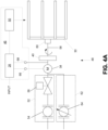
- a reel assembly includes the reel 30 and the reel drive system 48.
- the reel drive system 48 may include a first hydraulic subsystem 52 comprising a hydraulic pump 54 and at least one control valve 56, the first hydraulic subsystem 52 coupled to the motor 38, which in turn is coupled to the chain drive 40.
- the chain drive 40 is operatively coupled to a driveline 58, which in turn couples to the reel 30 via a bearing assembly 60.
- the first hydraulic subsystem 52 may be replaced with a second hydraulic subsystem 62 comprising a variable displacement hydraulic pump 64, the second hydraulic subsystem 62 coupled to the motor 38, with the balance of the components configured similarly to that described above.
- the chain drive 40 may either be omitted or replaced by another form of mechanical transmission, and/or the motor 38 may be replaced by a variable bypass hydraulic motor, an auxiliary powered shaft with a variable transmission, or electric motor.
- the control system 46 incudes the computing system 26 and plural sensors, including at least a first sensor 66 and a second sensor 68.
- the first sensor 66 is configured to measure (directly or indirectly) the rotational speed of the reel 30.
- the first sensor 66 is mounted to the outside of the motor 38 and monitors the motor output shaft rotation.
- the first sensor 66 may be positioned elsewhere, including at any location between the motor 38 and the reel 30 (e.g., proximal to the chain drive 40, the driveline 58, etc.).
- the first sensor 66 may be a Hall effect sensor, magnetic encoder, or in general any sensor that is based on magnetic reluctance (e.g., where a gear tooth passes by a coil and the changes in the magnetic field are detected). In one embodiment, the first sensor 66 may provide an output that comprises a frequency of pulses or indication of angular rotation that the computing system 26 uses to derive the speed of rotation using known equations. In some embodiments, the computing system 26 may use time, voltage, or current to determine speed. In some embodiments, the first sensor 66 may be embodied as an optical sensor (e.g., disposed in, or integrated with, the motor 38), ultrasonic sensor, or other known types of flowrate sensors. Note that in embodiments that use an electric drive, a current or voltage sensor may be used to detect speed indirectly. In some embodiments, some of the processing performed by the computing system 26 may be achieved at the first sensor 66 (and/or the second sensor 26).
- the second sensor 68 is configured to measure (directly or indirectly) drive pressure, and may be embodied as a torque sensor (e.g., coupled to the driveline 58), a load cell (e.g., coupled to the motor 38), or a pressure sensor (e.g., pressure transducer) that is coupled between the hydraulic subsystem 52 (or 62 in some embodiments) and the motor 38.
- a torque sensor e.g., coupled to the driveline 58
- load cell e.g., coupled to the motor 38
- a pressure sensor e.g., pressure transducer
- load may also be inferred by phase or time delay in sensed angular position sensors along the drive or end to end along the reel. Though depicted in FIG.
- the computing system 26 is communicatively coupled to the sensors 66, 68 via a wired or wireless connection (not shown).
- control system 46 is configured to receive input (e.g., operator input) corresponding to a reel setting for movement (e.g., reel height adjustment), measure speed and drive pressure (e.g., opposition force placed on the reel 30) from the sensors 66, 68, respectively, in operations at the reel setting, and determine a corresponding target load and in some embodiments, a window of minimum and maximum reel height setpoints.
- input e.g., operator input
- measure speed and drive pressure e.g., opposition force placed on the reel 30
- the carrier arms may be moved in a fore-and-aft manner as described above, which may be used based on the manner in which the crop is laying on the field.
- the computing system 26 continually receives feedback from the sensors 66, 68 and adjusts the reel height via signaling to the reel lift system 50 based on the speed and pressure measurements to maintain operations at or around the target load and/or within the window.
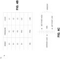
- an example data structure 70 e.g., look up table or LUT
- the computing system 26 may access to determine the load on the reel 30 based on the measurements of speed and pressure for a particular reel height setting.
- one or more additional data entries may be used (or alternative data structures may be used) as explained further below.
- the data structure 70 has a plurality of different speeds (e.g., S1-SN), and for each speed, a plurality of different pressure (e.g., P1-PNN) and load (e.g., L1-LNN) setting combinations.
- plural data structures 70 may be used.
- one or more parametric equations may be used in place of the data structures 70.
- pressure values e.g., P1-PN1 are prescribed for which the computing system 26 needs to instruct the reel lift system 50 (and in particular, signal control valve actuators for one or more control valves that control fluid flow into and out of the hydraulic cylinders 44 ( FIG. 3 ) for enabling adjustment of the carrier arms 42 ( FIG. 3 )) to adjust the height of the reel 30 to cause the change in pressure needed to maintain a speed at a given load.
- an operator may drive the windrower 10 ( FIG. 1 ) onto a field, set (e.g., INPUT in FIG. 4A ) the height adjustment for the reel 30, and begin field harvesting operations.
- the computing system 26 receives the input, and speed and pressure input signals from the sensors 66, 68, accesses the data structure 70, and determines a target load and, in some embodiments, a window of reel heights (and corresponding loads) through which the computing system 26 may cause adjustment to attempt to maintain a consistent load at or around the target load or at least within the window, as illustrated conceptually in FIG. 4C .
- the target (derived) load is determined, and centered (50%) in a window of reel height setpoint values (which correspond to minimum and maximum loads from the data structure 70), the window providing a range of values within which the computing system 26 attempts to adjust the reel height to approximate the target load when changes to the load occur (e.g., from a change in density or height of crop).
- a window is optional, the window facilitating an automated mechanism to augment operator commands.
- the computing system 26 may be allowed more autonomy, such as to operate freely about the target load (i.e., without the constraints of setpoints for the window).
- FIGS. 4A-4C is illustrative of an example operation of a reel height adjustment system.
- the target load and (optional) reel height adjustment window is determined as shown in FIGS. 4B-4C .
- the target load is L2.
- the windrower 10 While the windrower 10 is traversing the field, assume crop conditions change, leading to a pressure increase (from P2 to P3) corresponding to an increase in the load (from L2 to L3).
- the computing system 26 senses this change from input received via the sensors 66, 68 and in turn signals the reel lift system 50.
- the actuator(s) of the reel lift system 50 cause a change in flow to the hydraulic cylinders (e.g. cylinders 44, FIGS. 2B ), which extends the cylinder rod(s) to push up the carrier arms 42, resulting in a raising of the reel 30.
- the load on the reel 30 is reduced back to the setpoint or target load (L2).
- L2 target load
- the computing system 26 receives from the sensors 66, 68 an indication of the changed condition, and responsively signals the reel lift system 50 to lower the reel height, which in turn results in the load returning to the setpoint or the target load L2. In effect, the reel height adjustment system attempts to maintain a consistent or near consistent feed of crop to the machine.
- FIG. 5 illustrates an embodiment of an example computing system 26 that cooperates with the control system 46 to enable closed-loop control of reel speed and height adjustment.
- the computing system 26 is illustrative of one example, and that some embodiments of computing systems may comprise fewer or additional components, and/or some of the functionality associated with the various components depicted in FIG. 5 may be combined, or further distributed among additional modules and/or computing devices (e.g., plural ECUs), in some embodiments. It should be appreciated that, though described in the context of residing in the windrower 10 ( FIG.
- one or more of the functionality of the computing system 26 may be implemented in a computing device or devices located internal and external to the windrower 10 or completely external to the windrower 10, as described above.
- the computing system 26 is depicted in this example as a computer device (e.g., an electronic control unit or ECU), but may be embodied as a programmable logic controller (PLC), field programmable gate array (FPGA), application-specific integrated circuit (ASIC), discrete analog controller, among other devices.
- the computing system 26 may comprise two or more devices. It should be appreciated that certain well-known components of computer systems are omitted here to avoid obfuscating relevant features of the computing system 26.
- the computing system 26 comprises one or more processors, such as processor 72, input/output (I/O) interface(s) 74, and memory 76, all coupled to one or more data busses, such as data bus 78.
- the memory 76 may include any one or a combination of volatile memory elements (e.g., random-access memory RAM, such as DRAM, and SRAM, etc.) and nonvolatile memory elements (e.g., ROM, Flash, hard drive, EPROM, EEPROM, CDROM, etc.).
- the memory 76 may store a native operating system, one or more native applications, emulation systems, or emulated applications for any of a variety of operating systems and/or emulated hardware platforms, emulated operating systems, etc.
- the memory 76 comprises an operating system 80 and reel height adjustment software 82, which in one embodiment comprises a data structure 70 (described in association with FIG. 4B ).
- the reel height adjustment software 82 may comprise additional components or modules, including graphical user interface (GUI) software that presents feedback of current reel height, measures of pressure, speed, and/or load, and/or measures of sensed and/or derived crop features (e.g., crop height, crop-top contour, moisture, nutrients, etc.).
- GUI graphical user interface
- additional modules may include, for instance, a browser, or if located remotely, web-host network software, guidance software, communications software, etc., or in some embodiments, fewer software modules (e.g., combined functionality, omitted functionality) may be employed (or omitted) in the memory 76 or used in additional memory.
- a separate storage device may be coupled to the data bus 78 (or to a CAN bus (depicted in FIG. 5 as NETWORK) or other network via I/O interfaces 74), such as a persistent memory (e.g., optical, magnetic, and/or semiconductor memory and associated drives).
- the computing system 26 is further coupled to a network that is included as part of the control system 46 illustrated in FIG. 4A .
- the network may be configured as a controller area network (CAN) system, such as a network in conformance to the ISO 11783 standard, also referred to as "Isobus".
- CAN controller area network
- other proprietary or public (e.g., standards-based) network configurations may be used to enable signaling or communications among devices of the windrower 10 ( FIG. 1 ) and/or external devices, and in some embodiments, all or a portion of the communications may be achieved wirelessly (e.g., via Bluetooth, 802.11, near field communications (NFC), etc.).
- Coupled to the network are one or more sensors 84, which may include the sensors 66, 68, among other sensors including optical and/or other electromagnetic-based sensors (e.g., non-time of flight (TOF) devices including light beams/strips, stereoscopic imaging devices, and/or TOF devices, including lidar devices, radar devices, moisture height sensors, capacitive sensors, etc.).
- TOF time of flight
- TOF devices including lidar devices, radar devices, moisture height sensors, capacitive sensors, etc.
- the computing system 26 may place more emphasis (e.g., more weight) on the non-load type sensor data than the load-type sensors.
- Some embodiments may completely exclude the load sensing features in favor of more direct, crop height measurements.
- the parametric equation and/or LUT may have additional data entries for such conditions.
- Also coupled to the network may be one or more of global navigation satellite system (GNSS) receivers, real time kinematic (RTK) receivers, communication (COMM) devices (e.g., cellular and/or radio modems), among other devices.
- GNSS global navigation satellite system
- RTK real time kinematic
- COMP communication
- cellular and/or radio modems e.g., cellular and/or radio modems
- the reel height adjustment software 82 comprises executable code (instructions) that receives and processes plural inputs, and outputs control signals (e.g., on/off signals, proportional control signals) to one or more control valves of a manifold 86 of the reel lift system 50.
- control signals e.g., on/off signals, proportional control signals
- the reel height adjustment software 82 receives drive pressure and reel speed from the sensors 84 (or derives such parameters based on the signals received from the sensors 84), and is also configured to receive additional input (e.g., operator input corresponding to reel height settings, or input autonomously or semi-autonomously accessed from local or remote storage, such as past (historical) reel height settings for a given field identified by the operator or detected using GNSS navigation).
- the input may additionally, or alternatively, include one or more various electromagnetic signal input, including stereoscopic or 3D imaging of the crop to be harvested and/or indications of crop height from interference with a light strip or other electromagnetic-based detection technology.
- the reel height adjustment software 82 uses the received input to determine a target or derived load and an optional corresponding reel height window within which operation is prescribed.
- the reel height adjustment software 82 communicates with one or more control valves of the manifold 86 to cause a change in flow through the hydraulic cylinders 44, resulting in adjustments to reel height (e.g., to raise or lower the reel height, fore-and-aft movement, etc.) to maintain a substantially consistent operative load on the reel (e.g., operation at or about the target load or within the window).
- the reel height adjustment software 82 may comprise additional modules (executable code or instructions), including one or more parametric equations (eqn) module and/or an electromagnetic processing module (EPM, and also referred to as simply an electromagnetic module).
- the parametric equation module may be used in addition to the data structure 70 (e.g., as a check on the data structure 70 or as a redundant mechanism in case of corruption of the data structure 70), or in lieu of the data structure 70, to generate a target load (and determine pressure and speed parameters) based on variations from the target load.
- the parametric equation simulates at least in part one or more various known flow equations (e.g., Bernoulli's equation).
- the EPM module processes images captured from plural cameras of a stereoscopic imaging system mounted on the windrower 10 ( FIG.
- imaging may be achieved via a single packaged unit comprising stereoscopic cameras.
- Other and/or additional electromagnetic-based crop feature detection may be used in some embodiments. Additional discussion of certain embodiments of the EPM module is described below in conjunction with FIGS. 6A-6B .
- Execution of the reel height adjustment software 82 may be implemented by the processor 72 under the management and/or control of the operating system 80.
- the processor 72 may be embodied as a custom-made or commercially available processor, a central processing unit (CPU) or an auxiliary processor among several processors, a semiconductor based microprocessor (in the form of a microchip), a macroprocessor, one or more application specific integrated circuits (ASICs), a plurality of suitably configured digital logic gates, and/or other well-known electrical configurations comprising discrete elements both individually and in various combinations to coordinate the overall operation of the computing system 26.
- CPU central processing unit
- ASICs application specific integrated circuits
- the I/O interfaces 74 provide one or more interfaces to the CAN bus (NETWORK) and/or other networks.
- the I/O interfaces 74 may comprise any number of interfaces for the input and output of signals (e.g., comprising analog or digital data) for conveyance of information (e.g., data) over one or more networks.
- the input may comprise input by an operator (local or remote) through a user interface (Ul) 88, which may include input from switches and/or controllers from the cab or from other locations on the windrower 10 FIG.
- the user interface 88 includes one or any combination of a keyboard, joystick (e.g., with tactile motor), steering wheel, headset, mouse, microphone, display screen, touch-type or otherwise, among other types of input devices.
- communications components COMM
- GNSS global navigation satellite systems and/or related technology, including RTK
- storage devices e.g., memory, removable storage, persistent storage, etc.
- the user interface 88 includes one or any combination of a keyboard, joystick (e.g., with tactile motor), steering wheel, headset, mouse, microphone, display screen, touch-type or otherwise, among other types of input devices.
- Outputs may include signals to actuate the actuator(s) of the one or more control valves of the manifold 86, among other actuable devices and/or to provide operator feedback (e.g., visual, audible, and/or tactile) via corresponding devices (e.g., display screen and/or LEDs, speaker, tactile motor).
- operator feedback e.g., visual, audible, and/or tactile
- corresponding devices e.g., display screen and/or LEDs, speaker, tactile motor.
- a computer-readable medium may comprise an electronic, magnetic, optical, or other physical device or apparatus that may contain or store a computer program (e.g., executable code or instructions) for use by or in connection with a computer-related system or method.
- the software may be embedded in a variety of computer-readable mediums for use by, or in connection with, an instruction execution system, apparatus, or device, such as a computer-based system, processor-containing system, or other system that can fetch the instructions from the instruction execution system, apparatus, or device and execute the instructions.
- an instruction execution system, apparatus, or device such as a computer-based system, processor-containing system, or other system that can fetch the instructions from the instruction execution system, apparatus, or device and execute the instructions.
- computing system 26 When certain embodiment of the computing system 26 are implemented at least in part as hardware, such functionality may be implemented with any or a combination of the following technologies, which are all well-known in the art: a discrete logic circuit(s) having logic gates for implementing logic functions upon data signals, an application specific integrated circuit (ASIC) having appropriate combinational logic gates, a programmable gate array(s) (PGA), a field programmable gate array (FPGA), etc.
- ASIC application specific integrated circuit
- PGA programmable gate array
- FPGA field programmable gate array
- FIGS. 6A and 6B illustrate various embodiments of a reel height adjustment system that, through application of at least the EPM module ( FIG. 5 ), replaces or supplements the measurements of pressure and speed with electromagnetic-based crop feature detection (e.g., crop height) to trigger adjustments in reel movement.
- FIGS. 6A and 6B shown is a front portion of the windrower 10 including the cab 16 and the header 28 using stereoscopic imaging as one example functionality of the EPM module.
- the windrower 10 is depicted as advancing upon crop of a certain height (different in each figure for illustration).
- a stereoscopic imaging system 90 is positioned atop the cab 16.
- the stereoscopic imaging system 90 is centrally mounted at the front of the cab 16. Note that the imaging system 90 may be part (e.g., optical) of the sensors 84 described in association with FIG. 5 . In another embodiment, the stereoscopic imaging system 90 is disposed on the header 28, preferably centrally located atop the frame of the header 28. In some embodiments, the stereoscopic imaging system 90 may be disposed elsewhere on the windrower 10 or on the header 28.
- the stereoscopic imaging system 90 comprises a non-time-of-flight (TOF) imaging system, and may be embodied as multiple cameras residing within a single packaged unit.
- TOF non-time-of-flight
- the cameras are offset from one another to image the crop at a slightly different angle to provide imaging results that are processed by an image processing component of the reel height adjustment software 82 ( FIG. 5 ) to render a stereoscopic image.
- the multiple cameras may each reside in a respective package at offset locations from each other to provide a similar effect.
- the imaging system 90 is generally mounted in a location within a range and view point that enables the capture of images (and/or located in any of a plurality of places on the windrower 10) of crop material located ahead of the header 28 that is coupled to the front of the windrower 10.
- the cameras of the stereoscopic imaging system 90 are configured in one embodiment to operate in the visible light spectrum, and are depicted in this example as offset symmetrically across a longitudinal centerline of the windrower 10, although it is not necessary for the cameras of the stereoscopic imaging system 90 to be symmetrically offset or offset with respect to the centerline.
- the cameras are positioned to capture images of the crop material (e.g., uncut crops or weeds, or in some embodiments, cut crops) located proximal to, and in front of, the header 28 of the windrower 10.
- the captured image may reveal one or more crop features, such as a height of the crops along all or a portion of a width of the header 28, the density, top-contour, and/or moisture content (e.g., via the color).
- the pair of images captured by the cameras stereoscopic imaging system 90 are used by the reel height adjustment software 82 ( FIG. 5 ) to produce stereo images and in some embodiments, a point cloud (or otherwise, three dimensional coordinates). Although described in the context of cameras operating in the visible spectrum, some embodiments of the stereoscopic imaging system 90 may operate in the non-visible spectrum, such as the infrared, ultraviolet, ultrasonic, among other ranges.
- the reel height adjustment software 82 uses the imaging input to determine at least the crop height and then adjust the reel height based on the reel height to maintain a consistent target load on the reel 30.
- the reel height adjustment software 82 determines the reel height based on a difference in the crop height and the header height. The operator sets the desired height of the reel 30 (e.g., to ensure the depth of the lowest portion of the reel 30 suitably engages the crop), and based on variations in the crop height as detected by the stereoscopic imaging system 90, the reel height adjustment software 82 adjusts the height of the reel. In one embodiment, height adjustment is based strictly on the imaging. In some embodiments, height adjustment may be based on a combination of determined load and one or more electromagnetic-based detection mechanisms. In some embodiments, the combination of inputs may be weighted, depending on the amount or integrity of data from each source.
- the reel height adjustment software 82 may use sensor input from a light strip in addition to, or in lieu of, other mechanisms for providing parameters for load determination.
- the light strip may be used to detect the height of the crop similar to what the stereoscopic imaging system 90 is attempting to achieve.
- FIG. 2C shown in schematic are two primarily upright, extended-length light strips 92 on opposing sides of the header 20. Note that the light strips 92 may be part of the sensors 84 described in association with FIG. 5 .
- the light strips 92 may comprise plural sources of light 92A (e.g., plural light transmitters or a single transmitter and optics to reflect the beam multiple times) along the length of one of the strips and receivers 92B along the length of the opposing strip.
- the light beams that travel across the header 20 from source 92A (e.g., transmitter) to receiver 92B provide a mechanism by which, upon interruption from crop breaking the beam of light of one or more beams, a determination of crop height (based on how many beams of light are interrupted) can be made by the reel height adjustment software 82.
- the reel height adjustment software 82 can determine (e.g., based on a LUT or parametric equation) what adjustments in reel height are required to maintain proper engagement of the reel 30 with the crop, with the adjustments made autonomously or via cooperation/intervention with the operator.
- the light strips 92 are mounted to the header 20 in such a manner that the crop height is best determined from interruption of the beams of light from standing crop as the windrower 10 advances along the field.
- reel height adjustment may be based on electromagnetic-based crop feature detection in lieu of, or in addition to, the load-based determination explained above.
- one or more sensors may be mounted to the front of the header to measure relative capacitance, radiative reflectance, or relative absorbance of radio waves, microwaves, light, infrared, or other forms of radiation. The comparison of values at different heights provides an indication of an approximate crop height. This data may also provide other crop features, including crop moisture or nutrient data.
- one or more cameras may be used with image processing and or machine learning software to determine one or more crop features, including crop height and/or contour of the crop.
- crop dividers comprising a tube or channel of plural capacitive moisture sensors may be used to detect moisture. Digressing briefly, many crops have a measureable amount of moisture that may be differentiated from the surrounding air. Individual, discrete sensing elements may be used. For instance, a single broadcast amplifier in cooperation with plural antennas may be used to receive a signal to determine crop height. In some embodiments, a delay line or mismatched impedance behavior using a pair of conductors running along the length of the tube may be used, and digital signal processing is implemented on any reflected pulses to enable a determination of the height without measuring actual moisture levels. In some embodiments, digital signal processing may be omitted in place of duplicate lines where one comprises a transceiver at one end and the other at the base.
- reel height adjustment system may comprise all of the components shown in FIGS. 4A , 5 , and 6A-6B , or a subset thereof in some embodiments, or additional components in some embodiments.
- the various embodiments described above may be used in any combination or alone in some embodiments.
- FIG. 7 illustrates an example control algorithm 94 used in an embodiment of a reel height adjustment system.
- the control algorithm is implemented by the reel height adjustment software 82 running on one or more devices located on the windrower 10 ( FIG. 1 ), such as on the computing system 26, residing on devices both internal and external to the windrower 10 in some embodiments, or in some embodiments, running on a device external to, yet in communication with, the control components of the windrower 10.
- the control algorithm 94 upon commencement (start) of the algorithm, the control algorithm 94 reads sensors (96), and determines whether an optical sensor is installed (98).
- polling for (or generally receiving) locations or device identifiers coupled to the network enables the control algorithm 94 to determine if an electromagnetic-based crop feature detection device(s) (e.g., light strip or stereoscopic imaging system) is coupled to the network.
- an electromagnetic-based crop feature detection device(s) e.g., light strip or stereoscopic imaging system
- the availability of an optical sensor in the system may be acknowledged by an operator (e.g., via the user interface 88 ( FIG. 5 )).
- the process may not commence, or decisions on the presence of certain sensors may not be initiated, until crop is detected or until the reel is commanded up or down.
- the crop is imaged (stereoscopic imaging system 90, FIG. 5 , or sensed or detected, such as via light strips 92, FIG. 2C , capacitive sensors, moisture sensors, reflectance, radiating signal absorption, etc.) to determine crop height and/or other crop features.
- the load (target load) is determined (102), either based on the read sensors or the imaged/sensed crop or using a combination thereof, and a height window is calculated (104). Note that (102) may be calculated differently (e.g., ignored or smoothed or reset at baseline) if the reel is known to be out of crop or buried in crop.
- the algorithm 94 may choose to completely ignore one or more sensors if there is a determination that another sensor is more trustworthy. Self calibration may be running at some times or at all times.
- the control algorithm 94 determines whether the current load is within the window (106). If the current load is greater than a maximum setpoint, the reel is raised to attempt to bring the reel load (and pressure) back to the range of the window or the target load (108). If the current load is less than the minimum setpoint, the reel is lowered to attempt to bring the reel load (and pressure) back to the range of the window or the target load (110).
- a reel height adjustment method 112 depicted in FIG. 8 , which in one embodiment is implemented by the reel height adjustment software 82 ( FIG. 5 ) as executed by one or more processors, comprises measuring a rotational speed of the reel (114); measuring a force opposing rotation of the reel (116); determining a target load for the reel based on the measured rotational speed and the measured force and a first input (118); and causing movement of the reel according to the target load based on a change in load on the reel (120). For instance, causing movement according to the target load includes reaching or approximating the target load.
- a window with setpoints may also be determined for operation within the constraints of the window, causing said movement includes operation within the window.
- a reel height adjustment method 122 which in one embodiment is implemented by the reel height adjustment software 82 ( FIG. 5 ) as executed by one or more processors, comprises measuring a crop feature (124); determining a target parameter of a rotating mechanism of a header (126); and causing a change in movement of the rotating mechanism according to the target parameter based on a change in the measurement (128).
- the target parameter is a position of the rotating mechanism.
- the target parameter is a speed of rotation of the rotating mechanism.
- other and/or additional header components may be adjusted based on the target parameter and measurements.
- references to “one embodiment”, “an embodiment”, or “embodiments” mean that the feature or features being referred to are included in at least one embodiment of the technology.
- references to “one embodiment”, “an embodiment”, or “embodiments” in this description do not necessarily refer to the same embodiment and are also not mutually exclusive unless so stated and/or except as will be readily apparent to those skilled in the art from the description.
- a feature, structure, act, etc. described in one embodiment may also be included in other embodiments, but is not necessarily included.
- the present technology can include a variety of combinations and/or integrations of the embodiments described herein.
Claims (13)
- System mit:einem Erntevorsatz (28), wobei der Erntevorsatz (28) aufweist:eine Haspelbaugruppe mit mindestens einer Haspel (30);mehrere Tragarme (42), welche mit der Haspel (30) gekoppelt sind; undmehrere Zylinder (44), welche mit den mehreren Tragarmen (42) gekoppelt und konfiguriert sind, um die mehreren Tragarme (42) zu bewegen; undeinem Steuersystem (46), dadurch gekennzeichnet, dass das Steuerungssystem (46) aufweist:einen ersten Sensor (66), welcher konfiguriert ist, um die Drehgeschwindigkeit der Haspel (30) zu messen;einen zweiten Sensor (68), welcher konfiguriert ist, um eine der Drehung der Haspel (30) entgegengerichtete Kraft zu messen; undein Rechensystem (26), welches konfiguriert ist, um:basierend auf ersten Signalen des ersten und des zweiten Sensors (66, 68) und einer ersten Eingabe eine Soll-Last für die Haspel (30) zu bestimmen; undbasierend auf einer Änderung der Last auf der Haspel (30) durch Betätigung der mehreren Aktuatoren (44) eine Bewegung der Haspel (30) zu bewirken, um die Höhe der Haspel (30) anhand der Soll-Last einzustellen.
- System nach Anspruch 1, wobei die Haspelbaugruppe ein Haspelantriebssystem (48) aufweist, welches konfiguriert ist, um eine Drehung der Haspel (30) anzutreiben.
- System nach Anspruch 2, wobei der erste Sensor (66) funktionell mit dem Haspelantriebssystem (48) gekoppelt und konfiguriert ist, um durch Messen eines der Drehbewegung der Haspel (30) entsprechenden Parameters die Drehgeschwindigkeit der Haspel (30) zu messen.
- System nach Anspruch 1, wobei der zweite Sensor (68) einen Druckaufnehmer und/oder eine Kraftmessdose aufweist.
- System nach Anspruch 1, wobei der Erntevorsatz (28) einen Band- oder einen Schneckenerntevorsatz aufweist.
- System nach Anspruch 1, wobei die Haspelbaugruppe weiterhin eine oder mehrere zusätzliche Haspeln (30) aufweist.
- System nach Anspruch 1, wobei das Rechensystem (26) weiterhin konfiguriert ist, um:
durch Bestimmen eines Haspelhöhenfensters, welches minimale und maximale Arbeitshöhen und entsprechende Lastwerte aufweist und innerhalb wessen die Soll-Last erreicht wird, ein die Soll-Last umgebendes Fenster zu ermitteln, wobei das Berechnungssystem (26) konfiguriert ist, um basierend auf zweiten Signalen des ersten und des zweiten Sensors (66, 68) die Bewegung der Haspel (30) innerhalb des Haspelhöhenbereichs zu bewirken. - System nach Anspruch 7, wobei das Rechensystem (26) weiterhin konfiguriert ist, um die Bewegung zu bewirken, durch Bewirken, dass die mehreren Zylinder (44) entweder die Haspel (30) anheben, um die Last auf die Haspel (30) zu reduzieren, oder die Haspel (30) absenken, um die Last auf die Haspel (30) zu erhöhen.
- System nach Anspruch 7, wobei das Rechensystem (26) konfiguriert ist, um die Soll-Last zumindest teilweise basierend auf der ersten Eingabe zu bestimmen, welche Bedienereingaben und/oder einer Haspelhöheneinstellung entsprechende frühere Daten aufweist.
- System nach Anspruch 7, wobei das Rechensystem (26) konfiguriert ist, um die Soll-Last basierend auf einem Zugriff auf eine Datenstruktur, welche mit Druck-, Geschwindigkeits-, oder Lastdaten versehen ist, und/oder Ausführung einer parametrischen Gleichung und weiterhin basierend auf der ersten Eingabe, welche eine Eingabe eines Bedieners und/oder einer Haspelhöheneinstellung entsprechende frühere Daten aufweist, zu ermitteln.
- Computergesteuertes Verfahren zum Einstellen einer Höhe einer Haspel (30) eines Erntevorsatzes, wobei das Verfahren aufweist:Messen einer Drehgeschwindigkeit der Haspel (30);Messen einer der Drehung der Haspel (30) entgegengerichteten Kraft;Ermitteln einer Soll-Last auf die Haspel (30) basierend auf der gemessenen Drehgeschwindigkeit und der gemessenen Kraft und einer ersten Eingabe; undBewirken einer Bewegung der Haspel (30) basierend auf einer Änderung der Last auf die Haspel (30), um die Höhe der Haspel (30) anhand der Soll-Last einzustellen.
- Nichttemporäres computerlesbares Medium, welches mit Anweisungen kodiert ist, die bewirken, dass das System nach Anspruch 1 die Verfahrensschritte nach Anspruch 11 ausführt.
- Nichttemporäres computerlesbares Medium, nach Anspruch 12, wobei das nichttemporäre computerlesbare Medium weiterhin mit Anweisungen kodiert ist, die bewirken, dass der eine oder die mehreren Prozessoren:
durch Bestimmen eines Haspelhöhenfensters, welches minimale und maximale Arbeitshöhenwerte und entsprechende Lasten aufweist und in welchem die Ziel-Last erreicht wird, ein die Soll-Last umgebendes Fenster ermitteln, und basierend auf zusätzlichen Messungen der Rotationsgeschwindigkeit und der Kraft die Bewegung der Haspel innerhalb des Haspelhöhenfensters bewirken.
Applications Claiming Priority (2)
| Application Number | Priority Date | Filing Date | Title |
|---|---|---|---|
| US201862682185P | 2018-06-08 | 2018-06-08 | |
| PCT/IB2019/054223 WO2019234539A1 (en) | 2018-06-08 | 2019-05-22 | Auto reel height |
Publications (2)
| Publication Number | Publication Date |
|---|---|
| EP3800980A1 EP3800980A1 (de) | 2021-04-14 |
| EP3800980B1 true EP3800980B1 (de) | 2024-03-06 |
Family
ID=67226296
Family Applications (1)
| Application Number | Title | Priority Date | Filing Date |
|---|---|---|---|
| EP19737875.5A Active EP3800980B1 (de) | 2018-06-08 | 2019-05-22 | Autorollenhöhe |
Country Status (3)
| Country | Link |
|---|---|
| US (1) | US11903342B2 (de) |
| EP (1) | EP3800980B1 (de) |
| WO (1) | WO2019234539A1 (de) |
Families Citing this family (5)
| Publication number | Priority date | Publication date | Assignee | Title |
|---|---|---|---|---|
| US20210185918A1 (en) * | 2019-12-23 | 2021-06-24 | Cnh Industrial America Llc | Systems and methods for controlling a position of a reel of an agricultural header |
| US20210274710A1 (en) * | 2020-03-05 | 2021-09-09 | Cnh Industrial America Llc | Variable speed reel drive for a header of an agricultural harvester |
| US11659787B2 (en) * | 2020-04-03 | 2023-05-30 | Cnh Industrial America Llc | Harvesting head reel-crop engagement |
| US20220232770A1 (en) * | 2021-01-22 | 2022-07-28 | Deere & Company | Agricultural header control |
| BR102023016802A2 (pt) * | 2022-08-23 | 2024-03-05 | Cnh Industrial America Llc | Conjunto de molinete de uma colheitadeira agrícola |
Family Cites Families (16)
| Publication number | Priority date | Publication date | Assignee | Title |
|---|---|---|---|---|
| US3546860A (en) | 1969-03-27 | 1970-12-15 | Int Harvester Co | Automatic forward travel control |
| EP0787978B1 (de) * | 1993-06-28 | 2007-01-17 | CNH Belgium N.V. | Selbstfahrende landwirtschaftliche Erntemaschine |
| DE29724569U1 (de) | 1997-06-25 | 2002-05-16 | Claas Selbstfahr Erntemasch | Vorrichtung an Landmaschinen zur berührungslosen Abtastung von sich über dem Boden erstreckender Konturen |
| DE10339551A1 (de) | 2003-08-26 | 2005-04-14 | Claas Selbstfahrende Erntemaschinen Gmbh | Verfahren und Vorrichtung zur Steuerung eines höhenverstellbaren Schneidwerks |
| CA2505431C (en) * | 2005-03-22 | 2011-10-11 | Macdon Industries Ltd. | Swather with automatic reel control |
| DE102005059351A1 (de) * | 2005-12-09 | 2007-06-21 | Claas Selbstfahrende Erntemaschinen Gmbh | Hydrauliksystem für eine selbstfahrende Erntemaschine |
| DE102012106065A1 (de) * | 2012-07-06 | 2014-01-09 | Claas Selbstfahrende Erntemaschinen Gmbh | Mähdrescher |
| DE102013101444A1 (de) * | 2013-02-14 | 2014-08-14 | Claas Selbstfahrende Erntemaschinen Gmbh | Verfahren zum Betreiben einer selbstfahrenden Erntemaschine sowie selbstfahrende Erntemaschine |
| WO2014156675A1 (ja) * | 2013-03-25 | 2014-10-02 | ヤンマー株式会社 | コンバイン |
| EP3485717A1 (de) | 2014-09-12 | 2019-05-22 | Intelligent Agricultural Solutions, LLC | Durchflusssensor aus akustischem material |
| US9668412B2 (en) | 2015-05-01 | 2017-06-06 | Deere & Company | Harvesting head height control circuit |
| DE102015113527A1 (de) * | 2015-08-17 | 2017-02-23 | Claas Selbstfahrende Erntemaschinen Gmbh | Landwirtschaftliche Erntemaschine |
| DE102015118767A1 (de) | 2015-11-03 | 2017-05-04 | Claas Selbstfahrende Erntemaschinen Gmbh | Umfelddetektionseinrichtung für landwirtschaftliche Arbeitsmaschine |
| DE102016118637A1 (de) * | 2016-09-30 | 2018-04-05 | Claas Selbstfahrende Erntemaschinen Gmbh | Mähdrescher mit einem Schneidwerk und Steuerung eines Schneidwerks |
| US10034428B2 (en) * | 2016-10-05 | 2018-07-31 | Cnh Industrial America Llc | Agricultural header with cutter tracking reel |
| US10321631B2 (en) * | 2017-06-01 | 2019-06-18 | Cnh Industrial America Llc | Hydraulic system for a header of an agricultural harvester |
-
2019
- 2019-05-22 EP EP19737875.5A patent/EP3800980B1/de active Active
- 2019-05-22 WO PCT/IB2019/054223 patent/WO2019234539A1/en unknown
- 2019-05-22 US US16/973,387 patent/US11903342B2/en active Active
Also Published As
| Publication number | Publication date |
|---|---|
| US11903342B2 (en) | 2024-02-20 |
| WO2019234539A1 (en) | 2019-12-12 |
| EP3800980A1 (de) | 2021-04-14 |
| US20210243954A1 (en) | 2021-08-12 |
Similar Documents
| Publication | Publication Date | Title |
|---|---|---|
| EP3800980B1 (de) | Autorollenhöhe | |
| US10806078B2 (en) | Control system for adjusting conditioning rollers of work vehicle | |
| EP3400780B1 (de) | System zur automatischen steuerung von konditionierungs- und schwadanordnungen eines arbeitsfahrzeugs | |
| CA2881892C (en) | Self-propelled agricultural machine with dual driving modes | |
| US10813287B2 (en) | Control system for adjusting swath flap of windrowing work vehicle | |
| CA3004684C (en) | Control system for adjusting forming shield of windrowing work vehicle | |
| EP3141103B1 (de) | Verfahren und vorrichtung zur automatischen steuerung einer schnitthöhe einer landwirtschaftlichen erntemaschine | |
| WO2014093814A1 (en) | Predictive load estimation through forward vision | |
| US9668419B2 (en) | Automatic load control for self-propelled windrower | |
| US20190327893A1 (en) | Header float and skid plate adjustment | |
| EP3827656B1 (de) | Haspelmontierte lasermessung eines entevorsatzes | |
| US11510365B2 (en) | Harvesting header segment display and map | |
| GB2497577A (en) | Linkage control systems for agricultural tractor | |
| WO2014105927A1 (en) | Using a virtual boom to steer agricultural equipment along the edge of worked/unworked areas | |
| US20230403966A1 (en) | Agricultural vehicle with satellite and variable wheel speed turn control | |
| CN116456820A (zh) | 农作业机、农作业机控制程序、记录有农作业机控制程序的记录介质、农作业机控制方法 |
Legal Events
| Date | Code | Title | Description |
|---|---|---|---|
| STAA | Information on the status of an ep patent application or granted ep patent |
Free format text: STATUS: UNKNOWN |
|
| STAA | Information on the status of an ep patent application or granted ep patent |
Free format text: STATUS: THE INTERNATIONAL PUBLICATION HAS BEEN MADE |
|
| STAA | Information on the status of an ep patent application or granted ep patent |
Free format text: STATUS: THE INTERNATIONAL PUBLICATION HAS BEEN MADE |
|
| PUAI | Public reference made under article 153(3) epc to a published international application that has entered the european phase |
Free format text: ORIGINAL CODE: 0009012 |
|
| STAA | Information on the status of an ep patent application or granted ep patent |
Free format text: STATUS: REQUEST FOR EXAMINATION WAS MADE |
|
| 17P | Request for examination filed |
Effective date: 20210111 |
|
| AK | Designated contracting states |
Kind code of ref document: A1 Designated state(s): AL AT BE BG CH CY CZ DE DK EE ES FI FR GB GR HR HU IE IS IT LI LT LU LV MC MK MT NL NO PL PT RO RS SE SI SK SM TR |
|
| AX | Request for extension of the european patent |
Extension state: BA ME |
|
| DAV | Request for validation of the european patent (deleted) | ||
| DAX | Request for extension of the european patent (deleted) | ||
| STAA | Information on the status of an ep patent application or granted ep patent |
Free format text: STATUS: EXAMINATION IS IN PROGRESS |
|
| 17Q | First examination report despatched |
Effective date: 20210921 |
|
| P01 | Opt-out of the competence of the unified patent court (upc) registered |
Effective date: 20230518 |
|
| GRAP | Despatch of communication of intention to grant a patent |
Free format text: ORIGINAL CODE: EPIDOSNIGR1 |
|
| STAA | Information on the status of an ep patent application or granted ep patent |
Free format text: STATUS: GRANT OF PATENT IS INTENDED |
|
| INTG | Intention to grant announced |
Effective date: 20231211 |
|
| GRAS | Grant fee paid |
Free format text: ORIGINAL CODE: EPIDOSNIGR3 |
|
| GRAA | (expected) grant |
Free format text: ORIGINAL CODE: 0009210 |
|
| STAA | Information on the status of an ep patent application or granted ep patent |
Free format text: STATUS: THE PATENT HAS BEEN GRANTED |
|
| AK | Designated contracting states |
Kind code of ref document: B1 Designated state(s): AL AT BE BG CH CY CZ DE DK EE ES FI FR GB GR HR HU IE IS IT LI LT LU LV MC MK MT NL NO PL PT RO RS SE SI SK SM TR |
|
| REG | Reference to a national code |
Ref country code: CH Ref legal event code: EP |
|
| REG | Reference to a national code |
Ref country code: IE Ref legal event code: FG4D |
|
| REG | Reference to a national code |
Ref country code: DE Ref legal event code: R096 Ref document number: 602019047776 Country of ref document: DE |