EP3800945A1 - Power allocation method and related device - Google Patents
Power allocation method and related device Download PDFInfo
- Publication number
- EP3800945A1 EP3800945A1 EP18923800.9A EP18923800A EP3800945A1 EP 3800945 A1 EP3800945 A1 EP 3800945A1 EP 18923800 A EP18923800 A EP 18923800A EP 3800945 A1 EP3800945 A1 EP 3800945A1
- Authority
- EP
- European Patent Office
- Prior art keywords
- transport layers
- power allocation
- terminal device
- precoding
- information
- Prior art date
- Legal status (The legal status is an assumption and is not a legal conclusion. Google has not performed a legal analysis and makes no representation as to the accuracy of the status listed.)
- Granted
Links
- 238000000034 method Methods 0.000 title claims abstract description 51
- 239000010410 layer Substances 0.000 claims description 326
- 239000011229 interlayer Substances 0.000 claims description 81
- 239000011159 matrix material Substances 0.000 claims description 73
- 230000001427 coherent effect Effects 0.000 claims description 42
- 230000015654 memory Effects 0.000 claims description 32
- 238000004891 communication Methods 0.000 claims description 24
- 238000012545 processing Methods 0.000 claims description 20
- 230000005540 biological transmission Effects 0.000 abstract description 74
- 238000010586 diagram Methods 0.000 description 34
- 238000013461 design Methods 0.000 description 19
- 230000011664 signaling Effects 0.000 description 11
- 230000006870 function Effects 0.000 description 8
- 238000013507 mapping Methods 0.000 description 7
- 239000002356 single layer Substances 0.000 description 6
- 238000004590 computer program Methods 0.000 description 5
- 230000008859 change Effects 0.000 description 3
- 238000005516 engineering process Methods 0.000 description 3
- 230000002776 aggregation Effects 0.000 description 2
- 238000004220 aggregation Methods 0.000 description 2
- 230000006399 behavior Effects 0.000 description 2
- 239000000969 carrier Substances 0.000 description 2
- 125000004122 cyclic group Chemical group 0.000 description 2
- 238000000802 evaporation-induced self-assembly Methods 0.000 description 2
- 230000007774 longterm Effects 0.000 description 2
- 230000002093 peripheral effect Effects 0.000 description 2
- 230000008569 process Effects 0.000 description 2
- 230000004044 response Effects 0.000 description 2
- 239000004065 semiconductor Substances 0.000 description 2
- 239000007787 solid Substances 0.000 description 2
- 230000003595 spectral effect Effects 0.000 description 2
- 238000001774 stimulated Raman spectroscopy Methods 0.000 description 2
- 230000009286 beneficial effect Effects 0.000 description 1
- 239000003795 chemical substances by application Substances 0.000 description 1
- 238000013500 data storage Methods 0.000 description 1
- 230000006872 improvement Effects 0.000 description 1
- 238000003780 insertion Methods 0.000 description 1
- 230000037431 insertion Effects 0.000 description 1
- 238000007726 management method Methods 0.000 description 1
- 230000004048 modification Effects 0.000 description 1
- 238000012986 modification Methods 0.000 description 1
- 230000003287 optical effect Effects 0.000 description 1
- 239000013307 optical fiber Substances 0.000 description 1
- 230000011218 segmentation Effects 0.000 description 1
Images


Classifications
-
- H—ELECTRICITY
- H04—ELECTRIC COMMUNICATION TECHNIQUE
- H04W—WIRELESS COMMUNICATION NETWORKS
- H04W52/00—Power management, e.g. TPC [Transmission Power Control], power saving or power classes
- H04W52/04—TPC
- H04W52/06—TPC algorithms
- H04W52/14—Separate analysis of uplink or downlink
-
- H—ELECTRICITY
- H04—ELECTRIC COMMUNICATION TECHNIQUE
- H04W—WIRELESS COMMUNICATION NETWORKS
- H04W52/00—Power management, e.g. TPC [Transmission Power Control], power saving or power classes
- H04W52/04—TPC
- H04W52/06—TPC algorithms
- H04W52/14—Separate analysis of uplink or downlink
- H04W52/146—Uplink power control
-
- H—ELECTRICITY
- H04—ELECTRIC COMMUNICATION TECHNIQUE
- H04B—TRANSMISSION
- H04B7/00—Radio transmission systems, i.e. using radiation field
- H04B7/02—Diversity systems; Multi-antenna system, i.e. transmission or reception using multiple antennas
- H04B7/04—Diversity systems; Multi-antenna system, i.e. transmission or reception using multiple antennas using two or more spaced independent antennas
- H04B7/0413—MIMO systems
- H04B7/0426—Power distribution
-
- H—ELECTRICITY
- H04—ELECTRIC COMMUNICATION TECHNIQUE
- H04B—TRANSMISSION
- H04B7/00—Radio transmission systems, i.e. using radiation field
- H04B7/02—Diversity systems; Multi-antenna system, i.e. transmission or reception using multiple antennas
- H04B7/04—Diversity systems; Multi-antenna system, i.e. transmission or reception using multiple antennas using two or more spaced independent antennas
- H04B7/0413—MIMO systems
- H04B7/0456—Selection of precoding matrices or codebooks, e.g. using matrices antenna weighting
- H04B7/0486—Selection of precoding matrices or codebooks, e.g. using matrices antenna weighting taking channel rank into account
-
- H—ELECTRICITY
- H04—ELECTRIC COMMUNICATION TECHNIQUE
- H04W—WIRELESS COMMUNICATION NETWORKS
- H04W52/00—Power management, e.g. TPC [Transmission Power Control], power saving or power classes
- H04W52/04—TPC
- H04W52/38—TPC being performed in particular situations
- H04W52/42—TPC being performed in particular situations in systems with time, space, frequency or polarisation diversity
-
- H—ELECTRICITY
- H04—ELECTRIC COMMUNICATION TECHNIQUE
- H04W—WIRELESS COMMUNICATION NETWORKS
- H04W52/00—Power management, e.g. TPC [Transmission Power Control], power saving or power classes
- H04W52/04—TPC
- H04W52/18—TPC being performed according to specific parameters
- H04W52/24—TPC being performed according to specific parameters using SIR [Signal to Interference Ratio] or other wireless path parameters
- H04W52/242—TPC being performed according to specific parameters using SIR [Signal to Interference Ratio] or other wireless path parameters taking into account path loss
Definitions
- This application relates to the field of wireless network technologies, and in particular, to a power allocation method and a related device.
- a data transmission rate can be multiplied by using a multi-input multi-output (multi-input multi-output, MIMO) technology in a fourth generation (fourth Generation, 4G) long term evolution (long term evolution, LTE) system and a fifth generation (fifth generation, 5G) new radio (new radio, NR) system.
- MIMO multi-input multi-output
- 4G fourth generation
- 4G long term evolution
- 5G new radio
- NR new radio
- a MIMO technology that supports transmission of a plurality of parallel channels is usually referred to as spatial multiplexing.
- Data is divided into a plurality of data streams, and the data streams are simultaneously sent, to improve a data transmission rate.
- power allocation between codewords (code word, CW) is not supported.
- a new generation NodeB new generation NodeB, gNB
- gNB new generation NodeB
- user equipment user equipment, UE
- Embodiments of this application provide a power allocation method and a related device, to allocate different transmit powers to different transport layers, thereby improving transmission efficiency of a system.
- an embodiment of this application provides a power allocation method, including: A terminal device first receives first downlink control information sent by a network device, where the first downlink control information includes first power allocation information for a plurality of transport layers; then determines a first transmit power of each of the plurality of transport layers based on the first power allocation information; and finally sends first uplink data to the network device based on the first transmit power of each transport layer.
- the network device sends the power allocation information to the terminal device, to allocate different transmit powers to different transport layers, thereby improving transmission efficiency of a system.
- the terminal device may determine inter-layer power allocation capability information supported by each transport layer, and report the inter-layer power allocation capability information supported by each transport layer to the network device, so that the network device determines second power allocation information for the plurality of transport layers of the terminal device.
- the first downlink control information includes a precoding matrix indicator PMI or a spatial rank index SRI
- the terminal device may determine, based on the PMI or the SRI, precoding used by the plurality of transport layers. Then, an antenna port used by each transport layer is determined based on the precoding used by the plurality of transport layers, a maximum transmit power parameter of the antenna port of the terminal device is then obtained, and the inter-layer power allocation capability information is determined based on the maximum transmit power parameter of the antenna port.
- the first downlink control information further includes codeword-transport layer-precoding correspondence indication information
- the plurality of transport layers include at least two groups of transport layers.
- the terminal device may determine, based on the correspondence indication information, antenna ports used by the at least two groups of transport layers, and then determine the inter-layer power allocation capability information based on the antenna ports used by the at least two groups of transport layers.
- the inter-layer power allocation capability information may be determined based on the antenna ports used by the at least two groups of transport layers and a maximum transmit power parameter of the antenna port.
- the terminal device needs to determine the inter-layer power allocation capability information supported by each transport layer, and report the inter-layer power allocation capability information supported by each transport layer to the network device.
- the terminal device may send the inter-layer power allocation capability information to the network device by using higher layer signaling, to reduce physical layer signaling overheads and improve information transmission reliability.
- the inter-layer power allocation capability information may be carried on a PUSCH scheduled by UL grant and sent to the network device, so that information transmission reliability is ensured, and a delay of information transmission can be reduced.
- the terminal device receives second downlink control information sent by the network device, where the second downlink control information includes second power allocation information for the plurality of transport layers; and the terminal device determines a second transmit power of each of the plurality of transport layers based on the second power allocation information; and sends second uplink data based on the second transmit power of each transport layer.
- the PMI or the SRI in the first downlink control information is the same as a PMI or an SRI in the second downlink control information.
- the network device sends the power allocation information to the terminal device, to allocate different transmit powers to different transport layers, thereby improving transmission efficiency of a system.
- the first power allocation information is identified as a default state 0.
- the first downlink control information includes a precoding matrix indicator PMI, and the terminal device determines, based on the PMI, precoding used by the plurality of transport layers.
- the terminal device supports inter-layer power allocation, and may determine the first transmit power of each of the plurality of transport layers based on the first power allocation information.
- the first downlink control information includes a precoding matrix indicator PMI and codeword-transport layer-precoding correspondence indication information
- the plurality of transport layers include at least two groups of transport layers.
- the terminal device determines, based on the PMI, precoding used by the plurality of transport layers, and determines, based on the correspondence indication information, antenna ports used by the at least two groups of transport layers; and when the precoding used by the plurality of transport layers is partial coherent precoding, and the antenna ports used by the at least two groups of transport layers are the same, the terminal device supports inter-layer power allocation, and may determine the first transmit power of each of the plurality of transport layers based on the first power allocation information.
- the terminal device determines whether an error occurs during decoding of the first downlink control information, for example, whether the power allocation information is used as a virtual information check bit.
- the terminal device re-parses the power allocation information in the downlink control information. For example, a bit field is used as a TPC field, to indicate an adjustment value of a transmit power for transmitting a PUSCH by UE compared with a transmit power for transmitting the PUSCH last time.
- an embodiment of this application provides a power allocation method, including: A network device first sends first downlink control information to a terminal device, where the first downlink control information includes first power allocation information for a plurality of transport layers, and the first power allocation information is used to indicate the terminal device to determine a first transmit power of each of the plurality of transport layers and send first uplink data based on the first transmit power of each transport layer; and the network device receives the first uplink data sent by the terminal device.
- the network device sends the power allocation information to the terminal device, to allocate different transmit powers to different transport layers, thereby improving transmission efficiency of a system.
- the network device determines second power allocation information for the plurality of transport layers based on inter-layer power allocation capability information; and sends second downlink control information to the terminal device, where the second downlink control information includes the second power allocation information for the plurality of transport layers, and the second power allocation information is used to indicate the terminal device to determine a second transmit power of each of the plurality of transport layers and send second uplink data to the network device based on the second transmit power of each transport layer.
- a PMI or an SRI in the first downlink control information is the same as a PMI or an SRI in the second downlink control information.
- the network device sends the power allocation information to the terminal device, to allocate different transmit powers to different transport layers, thereby improving transmission efficiency of a system.
- the inter-layer power allocation capability information sent by the terminal device by using higher layer signaling is received.
- physical layer signaling overheads are reduced, and information transmission reliability is improved.
- a time-varying characteristic of a channel is extremely slow, and the network device may estimate an uplink channel based on a combination of SRSs sent by the terminal device for a plurality of times, to obtain accurate uplink channel information, so that the power allocation information for the transport layers can be introduced into the downlink control information.
- an embodiment of this application provides a network device.
- the network device is configured to implement the method and the functions performed by the network device in the first aspect, and is implemented by hardware/software.
- the hardware/software of the network device includes modules corresponding to the foregoing functions.
- an embodiment of this application provides a terminal device.
- the user equipment is configured to implement the method and the functions performed by the terminal device in the second aspect, and is implemented by hardware/software.
- the hardware/software of the terminal device includes modules corresponding to the foregoing functions.
- an embodiment of this application provides another terminal device, including a processor, a memory, and a communications bus.
- the communications bus is configured to implement connection and communication between the processor and the memory, and the processor executes a program stored in the memory to implement the steps in the power allocation method according to the first aspect.
- the terminal device provided in this application may include a corresponding module configured to perform behavior of the network device in the foregoing method and design.
- the module may be software and/or hardware.
- an embodiment of this application provides another network device, including a processor, a memory, and a communications bus.
- the communications bus is configured to implement connection and communication between the processor and the memory, and the processor executes a program stored in the memory to implement the steps in the power allocation method according to the second aspect.
- the network device provided in this application may include a corresponding module configured to perform behavior of the user equipment in the foregoing method and design.
- the module may be software and/or hardware.
- this application provides a computer-readable storage medium.
- the computer-readable storage medium stores an instruction, and when the instruction is run on a computer, the computer is enabled to perform the method according to the foregoing aspects.
- this application provides a computer program product including an instruction.
- the computer program product runs on a computer, the computer is enabled to perform the method according to the foregoing aspects.
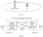
- FIG. 1 is a schematic structural diagram of a power allocation system according to an embodiment of this application.
- the power allocation system includes a terminal device and a network device.
- the terminal device may refer to a device that provides a voice and/or data connection to a user, or may be connected to a computing device such as a laptop computer or a desktop computer, or may be an independent device such as a personal digital assistant (personal digital assistant, PDA).
- PDA personal digital assistant
- the terminal device may alternatively be a station (station, STA), a system, a subscriber unit, a subscriber station, a mobile station, a mobile console, a remote station, an access point, a remote terminal, an access terminal, a user terminal, a user agent, or a user apparatus.
- the network device may be a base station, a NodeB, an evolved Node (environment Bureau, eNB), or a 5G next generation NodeB (next generation base station, gNB), and is a device in an access network that communicates with a wireless terminal over an air interface by using one or more sectors.
- the network device may serve as a router between the wireless terminal and another part in the access network, and the access network may include an internet protocol network.
- the network device may further coordinate attribute management of the air interface.
- Transport block Data sent from a medium access control (medium access control, MAC) layer to a physical layer is the TB.
- One TB corresponds to one data block, and the data block is sent within one transmission time interval (transmission time interval, TTI), and is also a unit of hybrid automatic repeat request (hybrid automatic repeat request, HARQ) retransmission.
- TTI transmission time interval
- HARQ hybrid automatic repeat request
- the UE sends a maximum of two TBs in one TTI.
- an eNB sends a maximum of two TBs to the UE in one TTI
- the UE sends a maximum of two TBs to the eNB in one TTI.
- a plurality of UEs may be scheduled in one TTI. Therefore, the eNB may simultaneously send or receive more than two TBs in one TTI.
- the UE may simultaneously receive data from a plurality of carriers, or may send data on a plurality of carriers. Therefore, the UE may send or receive more than two TBs in one TTI.
- the UE may send or receive a maximum of two TBs in one TTI on a carrier.
- the codeword may be considered as a TB with error protection.
- the codeword is a data bitstream obtained by performing processing such as cyclic redundancy check (cyclic redundancy check, CRC) insertion, code block segmentation, channel coding, or rate matching, on a TB sent in a TTI.
- CRC cyclic redundancy check
- Each codeword corresponds to one TB. Therefore, UE sends a maximum of two codewords in one TTI.
- Transport layer Layer mapping is performed on a modulation symbol obtained after scrambling and modulation are performed on one or two CWs, and the modulation symbol is mapped to a maximum of four transport layers. Each transport layer corresponds to a valid data stream.
- a quantity of transport layers that is, a quantity of layers, is referred to as a transmission order or a transmission rank, where the transmission rank may dynamically change.
- the mapping from one codeword to one or more transport layers may be considered as a process in which a codeword is equally divided into N parts and each part is placed at a transport layer. N herein is equal to a quantity of layers to which one codeword needs to be mapped.
- a full name is a precoding vector or a precoding matrix, and a process of precoding is mapping a transport layer to an antenna port by using the precoding matrix.
- a precoding matrix is an RxP matrix, where R is a transmission rank, and P is a quantity of antenna ports. Detailed descriptions are provided below.
- Antenna port (antenna port): The antenna port is a logical concept.
- One antenna port may be one physical transmit antenna, or may be a combination of a plurality of physical transmit antennas.
- UE cannot distinguish between the two cases, and a receiver of the UE cannot decompose a signal from a same antenna port.
- FIG. 2 is a schematic diagram of an equivalent channel between antenna ports according to an embodiment of this application.
- each antenna port corresponds to one reference signal (reference signal, RS), and the UE may determine channel estimation of the antenna port based on the RS, to demodulate data transmitted on the antenna port.
- RS reference signal
- Each antenna port corresponds to a group of resource elements (resource element, RE), and is used to transmit an RS.
- FIG. 3 is a schematic diagram of a mapping relationship according to an embodiment of this application.
- a codeword or a TB is divided into a CW 1 and a CW 2.
- the CW 1 and the CW 2 are respectively mapped to five transport layers, six transport layers, seven transport layers, or eight transport layers.
- the codeword at the transport layer is mapped to an antenna port through precoding.
- both an LTE system and an NR system support uplink spatial multiplexing.
- a plurality of CWs or a single CW sent by UE is transmitted at a plurality of transport layers.
- a gNB needs to obtain an uplink channel of the UE, to allocate precoding to the UE.
- NR supports two uplink transmission schemes, including codebook-based uplink transmission and non-codebook-based uplink transmission. The following describes the two uplink transmission schemes in detail.
- FIG. 4 is a schematic diagram of codebook-based uplink transmission according to an embodiment of this application. The following steps are included: First, the UE sends an omnidirectional sounding reference signal (sounding reference signal, SRS) signal to the gNB. Then, after receiving the SRS, the gNB estimates an uplink channel of the UE based on the SRS, and sends downlink control information (downlink control information, DCI) to the UE.
- the DCI includes a precoding matrix indicator (precoding matrix indication, PMI), and the PMI is used to indicate a quantity of CWs, a quantity of transport layers, and precoding that are used by the UE.
- precoding matrix indication precoding matrix indication
- the UE receives the PMI sent by the gNB, and performs uplink transmission based on the PMI.
- a precoding matrix of a limited set is defined for each transmission rank, where the set is also referred to as a codebook.
- the gNB selects a precoding matrix, and notifies the UE of an index of the precoding matrix.
- the UE determines a corresponding precoding matrix based on the index, and then transmits a physical uplink shared channel (physical uplink shared channel, PUSCH) based on the precoding matrix.
- PUSCH physical uplink shared channel
- FIG. 5 is a schematic diagram of precoding information of two antenna ports and a quantity of layers according to an embodiment of this application, including a bit field mapped to index, a quantity of transport layers, and a number of a precoding matrix.
- FIG. 6(A) is a schematic diagram of a precoding matrix for single-layer transmission by using two antenna ports according to an embodiment of this application, including precoding matrices respectively corresponding to a TPMI 0 to a TPMI 5 when the single-layer transmission is performed by using the two antenna ports.
- FIG. 6(A) is a schematic diagram of a precoding matrix for single-layer transmission by using two antenna ports according to an embodiment of this application, including precoding matrices respectively corresponding to a TPMI 0 to a TPMI 5 when the single-layer transmission is performed by using the two antenna ports.
- FIG. 6(B) is a schematic diagram of a precoding matrix for two-layer transmission by using two antenna ports according to an embodiment of this application, including precoding matrices respectively corresponding to a TPMI 0 to a TPMI 2 when the two-layer transmission is performed by using the two antenna ports.
- FIG. 6(A) For another example, in FIG.
- FIG. 7 is a schematic diagram of precoding information of four antenna ports and a quantity of layers according to an embodiment of this application, including a bit field mapped to index, a quantity of transport layers, and a number of a precoding matrix.
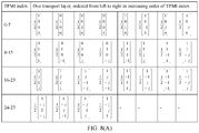
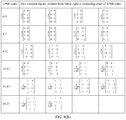
- FIG. 8(A) is a schematic diagram of a precoding matrix for single-layer transmission by using four antenna ports according to an embodiment of this application, including precoding matrices respectively corresponding to a TPMI 0 to a TPMI 27 when the single-layer transmission is performed by using the four antenna ports.
- FIG. 8(A) is a schematic diagram of a precoding matrix for single-layer transmission by using four antenna ports according to an embodiment of this application, including precoding matrices respectively corresponding to a TPMI 0 to a TPMI 27 when the single-layer transmission is performed by using the four antenna ports.
- FIG. 8(B) is a schematic diagram of a precoding matrix for two-layer transmission by using four antenna ports according to an embodiment of this application, including precoding matrices respectively corresponding to a TPMI 0 to a TPMI 21 when the two-layer transmission is performed by using the four antenna ports.
- FIG. 8(C) is a schematic diagram of a precoding matrix for three-layer transmission by using four antenna ports according to an embodiment of this application, including precoding matrices respectively corresponding to a TPMI 0 to a TPMI 6 when the three-layer transmission is performed by using the four antenna ports.
- FIG. 8(D) is a schematic diagram of a precoding matrix for four-layer transmission by using four antenna ports according to an embodiment of this application, including precoding matrices respectively corresponding to a TPMI 0 to a TPMI 4 when the four-layer transmission is performed by using the four antenna ports.
- FIG. 8(A) For another example, in FIG.
- each matrix or vector in the foregoing codebook may be referred to as precoding.
- Each row of the precoding corresponds to one antenna port, and each column corresponds to one transport layer. Therefore, a quantity of rows of the precoding is the same as a quantity of antenna ports.
- the foregoing precoding may be classified into three types: non-coherent precoding, partial coherent precoding, and full coherent precoding.
- non-coherent precoding In data transmission corresponding to non-coherent precoding, only one antenna port is used by each transport layer. For example, in a precoding matrix 1 2 1 0 0 0 0 1 0 0 0 0 1 0 0 0 0 1 , there is only one non-zero element in each column, indicating that one antenna port is used by each transport layer.
- the precoding matrix is non-coherent precoding.
- the partial coherent precoding is a precoding matrix in which more than one antenna port but not all antenna ports are used by at least one transport layer. For example, in a precoding matrix 1 2 2 1 1 0 0 0 0 1 1 1 ⁇ 1 0 0 0 0 1 ⁇ 1 , there are two non-zero elements in each column, indicating that two antenna ports are used by each transport layer. Therefore, the precoding matrix is partial coherent precoding.
- the full coherent precoding is a precoding matrix in which all antenna ports are used by each transport layer.
- the precoding matrix is full coherent precoding.
- FIG. 9 is a schematic diagram of non-codebook-based uplink transmission according to an embodiment of this application. The following steps are included: First, the gNB sends a downlink reference signal, for example, a channel state information reference signal (channel state information reference signal, CSI-RS), to the UE. Then, the UE estimates an uplink channel based on the downlink reference signal, where the downlink reference signal and uplink transmission are in a same frequency band, and sends a directional SRS, that is, an SRS with precoding, to the gNB based on the estimated uplink channel.
- CSI-RS channel state information reference signal
- the gNB sends DCI to the UE, where the DCI includes an SRI, and the SRI is used to indicate a quantity of CWs, a quantity of transport layers, and precoding that are used by the UE.
- the gNB does not know specific information about precoding used by the UE, but only determines precoding performance based on energy of the received SRS, to schedule the UE to use precoding with relatively good performance.
- the UE performs uplink transmission based on indication information of the SRI.
- an eNB indicates, by using a DCI format 4, parameters, namely, a quantity of CWs, a quantity of transport layers, and a precoding matrix, related to spatial multiplexing used by the UE for uplink transmission of a PUSCH.
- the DCI format 4 further includes a transmit power control (transmission power control, TPC) field, used to indicate an adjustment value of a transmit power for transmitting a PUSCH by the UE compared with a transmit power for transmitting the PUSCH last time. For example, if an indication is +1 dB, it indicates that the transmit power for transmitting the PUSCH this time is 1 dB greater than the transmit power for transmitting the PUSCH last time.
- TPC transmission power control
- the TPC is further used to indicate all CWs and all transport layers for the PUSCH.
- a total transmit power of the UE is limited (which is generally approximately 23 dBm). Therefore, the eNB cannot increase the transmit power of the UE to an unlimited extent. Therefore, the UE needs to approximately periodically report a transmit power headroom PH while transmitting the PUSCH.
- the eNB may consider increasing the transmit power of the UE, which is generally specifically embodied as increasing a transmit bandwidth or increasing a transmit power spectral density through TPC.
- the transmit power of the UE is limited (which is generally approximately 23 dBm).
- the eNB cannot increase the transmit power of the UE to an unlimited extent. Therefore, the UE needs to approximately periodically report a power headroom response (power headroom response, PHR) of the UE while transmitting the PUSCH.
- PHR power headroom response
- the eNB may consider increasing the transmit power of the UE, for example, increasing a transmit bandwidth or increasing a transmit power spectral density through TPC.
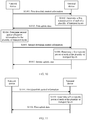
- FIG. 10 is a schematic flowchart of a power allocation method according to an embodiment of this application.
- a terminal device is configured to report inter-layer power allocation capability information supported by a plurality of transport layers.
- the method in this embodiment of this application includes at least the following steps.
- a network device sends first downlink control information to the terminal device.
- the first downlink control information may be an uplink scheduling grant (UL grant).
- the first downlink control information includes first power allocation information for the plurality of transport layers.
- this embodiment of this application is applicable to non-codebook-based uplink transmission.
- a time-varying characteristic of a channel is extremely slow, and the network device may estimate an uplink channel based on a combination of SRSs sent by the terminal device for a plurality of times, to obtain accurate uplink channel information, so that the power allocation information for the transport layers can be introduced into the downlink control information.
- the network device may specifically configure the power allocation information for the transport layers, for example, allocate a same transmit power to a plurality of transport layers that belong to a same codeword, and allocate different transmit powers to transport layers that belong to different codewords, thereby implementing power allocation for a plurality of codewords.
- the inter-codeword power allocation is a subset of the transport layer power allocation. In this embodiment of this application, the inter-codeword power allocation may be used as a specific implementation for all solutions for the transport layer power allocation.
- the terminal device determines a first transmit power of each of the plurality of transport layers based on the first power allocation information.
- the network device may identify the first power allocation information as a default state 0. After receiving the first power allocation information, the terminal device allocates the transmit power of each transport layer based on the default state 0. Therefore, it is ensured that the terminal device performs an operation based on the DCI sent by the network device.
- the terminal device may determine inter-layer power allocation capability information supported by each transport layer, and report the inter-layer power allocation capability information supported by each transport layer to the network device, so that the network device determines second power allocation information for the plurality of transport layers of the terminal device. Specifically, the following several optional manners are included.
- the first downlink control information includes a precoding matrix indicator PMI or a spatial rank index (spatial rank index, SRI), and the terminal device may determine, based on the PMI or the SRI, precoding used by the plurality of transport layers, a quantity of CWs, and a quantity of the transport layers. Further, an antenna port used by each transport layer is determined based on the precoding used by the plurality of transport layers, a maximum transmit power parameter of the antenna port of the terminal device is then obtained, and finally, the inter-layer power allocation capability information supported by each transport layer is determined based on the maximum transmit power parameter.
- PMI or SRI spatial rank index
- SRI spatial rank index
- the first downlink control information further includes codeword-transport layer-precoding (CW-layer-precoding) correspondence indication information
- the plurality of transport layers include at least two groups of transport layers.
- the terminal device may determine, based on the correspondence indication information, antenna ports used by the at least two groups of transport layers, and then determine, based on the antenna ports used by the at least two groups of transport layers, the inter-layer power allocation capability information supported by each transport layer.
- CW-layer-precoding codeword-transport layer-precoding
- the inter-layer power allocation capability information may be determined based on the antenna ports used by the at least two groups of transport layers and a maximum transmit power parameter of the antenna port.
- the inter-layer power allocation capability information of the terminal device is related to the correspondence indication information. For example, if UE needs to send a CW 0 and a CW 1, in a precoding matrix 1 2 2 1 1 0 0 0 0 1 1 1 ⁇ 1 0 0 0 0 1 ⁇ 1 , in a conventional LTE or NR system, it is considered by default that the first two columns are used to transmit the CW 0, and the last two columns are used to send the CW 1.
- the correspondence indication information indicates to allocate the first column and the third column of the precoding matrix to the CW 0, and allocate the second column and the fourth column of the precoding matrix to the CW 1
- the first column and the third column indicate that a transport layer 1 and a transport layer 3 are grouped into a group of transport layers, and the CW 0 is sent through the antenna port 1 to the antenna port 4
- the second column and the fourth column indicate that a transport layer 2 and a transport layer 4 are grouped into another group of transport layers, and the CW 1 is sent through the antenna port 1 to the antenna port 4.
- Uplink data is transmitted through same antenna ports by using the CW 0 and the CW 1. Therefore, the power may be allocated in any proportion without being affected by the antenna hardware parameter.
- the precoding used by the plurality of transport layers is full coherent precoding or partial coherent precoding, and the antenna ports used by the at least two groups of transport layers are the same, the power may be allocated in any proportion because the same antenna ports are used by different CWs for sending the uplink data, and the inter-layer power allocation capability information does not need to be reported.
- the terminal device needs to determine the inter-layer power allocation capability information supported by each transport layer, and report the inter-layer power allocation capability information supported by each transport layer to the network device.
- the terminal device when receiving a precoding matrix x indicated by the PMI sent by the network device, the terminal device determines that the precoding matrix x is non-coherent precoding, and therefore reports, to the network device, inter-layer power allocation capability information corresponding to the precoding matrix x, so that the network device reallocates power allocation information corresponding to the precoding matrix x.
- the terminal device sends first uplink data to the network device based on the first transmit power of each transport layer.
- the first uplink data includes the inter-layer power allocation capability information.
- the terminal device may send the inter-layer power allocation capability information to the network device by using higher layer signaling, for example, a MAC CE, to reduce physical layer signaling overheads and improve information transmission reliability.
- the inter-layer power allocation capability information may be carried on a PUSCH scheduled by the UL grant and sent to the network device, so that information transmission reliability is ensured, and a delay of information transmission can be reduced.
- the network device determines second power allocation information for the plurality of transport layers based on the inter-layer power allocation capability information.
- the network device sends second downlink control information to the terminal device.
- the second downlink control information includes a PMI or an SRI, and the second power allocation information for the plurality of transport layers.
- the PMI or the SRI in the first downlink control information is the same as the PMI or the SRI in the second downlink control information.
- the terminal device determines a second transmit power of each of the plurality of transport layers based on the second power allocation information.
- the terminal device sends second uplink data to the network device based on the second transmit power of each transport layer.
- the terminal device is configured to report the inter-layer power allocation capability information supported by the plurality of transport layers.
- the terminal device determines the inter-layer power allocation capability information supported by each transport layer, and returns the inter-layer power allocation capability information to the network device.
- the network device reallocates the power allocation information for the plurality of transport layers based on the inter-layer power allocation capability information, and sends the power allocation information to the terminal device, so that the terminal device sends the uplink data based on the allocated power allocation information.
- Different transmit powers are allocated to different transport layers based on the power allocation information, thereby improving transmission efficiency of the system.
- FIG. 11 is a schematic flowchart of another power allocation method according to an embodiment of this application.
- a terminal device is not configured to report inter-layer power allocation capability information supported by a plurality of transport layers.
- the method in this embodiment of this application includes at least the following steps.
- a network device sends first downlink control information to the terminal device, where the first downlink control information may be an uplink scheduling grant (UL grant), and the first downlink control information includes first power allocation information for a plurality of transport layers.
- the first downlink control information may be an uplink scheduling grant (UL grant)
- UL grant uplink scheduling grant
- the first downlink control information includes first power allocation information for a plurality of transport layers.
- this embodiment of this application is applicable to codebook-based uplink transmission. That the network device sends a PMI indicates that the network device knows precoding that is allocated to the terminal device and that is used for uplink transmission, and that the network device sends an SRI indicates that the network device does not know precoding that is used by the terminal device and that is used for uplink transmission. Therefore, in a scenario in which the terminal device does not feed back the inter-layer power allocation capability information, the UL grant includes the PMI but does not include the SRI, and only the PMI may support inter-layer power allocation.
- the network device enables the inter-layer power allocation for the terminal device by using higher layer signaling.
- the terminal device determines a first transmit power of each of the plurality of transport layers based on the first power allocation information.
- the first downlink control information includes a precoding matrix indicator PMI, and the terminal device determines, based on the PMI, precoding used by the plurality of transport layers.
- the terminal device supports the inter-layer power allocation, and may determine the first transmit power of each of the plurality of transport layers based on the first power allocation information.
- a precoding matrix 1 4 1 1 1 1 1 1 1 ⁇ 1 1 ⁇ 1 1 1 ⁇ 1 ⁇ 1 1 ⁇ 1 ⁇ 1 ⁇ 1 ⁇ 1 1 ⁇ 1 1 ⁇ 1 1 ⁇ 1 1 ⁇ 1 1 ⁇ 1 1 ⁇ 1 1 ⁇ 1 1 ⁇ 1 1 ⁇ 1 1 ⁇ 1 1 ⁇ 1 1 , there are four non-zero elements in each column, indicating that four antenna ports are used by each transport layer for sending uplink data. Therefore, power may be allocated in any proportion without being affected by an antenna hardware parameter.
- a precoding matrix 1 2 1 0 0 0 0 0 1 0 0 0 0 1 0 0 0 0 1 , there is one non-zero element in each column, indicating that only one antenna port is used by each transport layer for sending the uplink data. Because hardware parameters of antenna ports are different, when UE does not feed back the inter-layer power allocation capability information, and even if DCI sent by an eNB includes power allocation information, the
- the first downlink control information includes a precoding matrix indicator PMI and codeword-transport layer-precoding correspondence indication information
- the plurality of transport layers include at least two groups of transport layers.
- the terminal device determines, based on the PMI, precoding used by the plurality of transport layers, and determines, based on the correspondence indication information, antenna ports used by the at least two groups of transport layers; and when the precoding used by the plurality of transport layers is partial coherent precoding, and the antenna ports used by the at least two groups of transport layers are the same, the terminal device supports inter-layer power allocation, and may determine the first transmit power of each of the plurality of transport layers based on the first power allocation information.
- the inter-layer power allocation capability information of the terminal device is related to the correspondence indication information. For example, if UE needs to send a CW 0 and a CW 1, in a precoding matrix 1 2 2 1 1 0 0 0 0 1 1 1 ⁇ 1 0 0 0 0 1 ⁇ 1 , in a conventional LTE or NR system, it is considered by default that the first two columns are used to transmit the CW 0, and the last two columns are used to send the CW 1.
- the correspondence indication information indicates to allocate the first column and the third column of the precoding matrix to the CW 0, and allocate the second column and the fourth column of the precoding matrix to the CW 1
- the first column and the third column indicate that a transport layer 1 and a transport layer 3 are grouped into a group of transport layers, and the CW 0 is sent through the antenna port 1 to the antenna port 4
- the second column and the fourth column indicate that a transport layer 2 and a transport layer 4 are grouped into another group of transport layers, and the CW 1 is sent through the antenna port 1 to the antenna port 4.
- Uplink data is transmitted through same antenna ports by using the CW 0 and the CW 1. Therefore, the power may be allocated in any proportion without being affected by the antenna hardware parameter.
- the terminal device sends first uplink data to the network device based on the first transmit power of each transport layer.
- the terminal device determines whether an error occurs during decoding of the first downlink control information, for example, whether the power allocation information is used as a virtual information check bit.
- the terminal device re-parses the power allocation information in the downlink control information. For example, a bit field is used as a TPC field, to indicate an adjustment value of a transmit power for transmitting a PUSCH by UE compared with a transmit power for transmitting the PUSCH last time.
- the terminal device is not configured to report the inter-layer power allocation capability information supported by the plurality of transport layers, and the network device sends the first downlink control information to the terminal device, where the first downlink control information includes the first transmit power.
- the terminal device needs to determine whether the inter-layer power allocation is supported, and when the terminal device supports the inter-layer power allocation, the terminal sends the first uplink data to the network device based on the first transmit power of each transport layer, and allocates different transmit powers to different transport layers based on the power allocation information, thereby improving transmission efficiency of a system.
- FIG. 12 is a schematic structural diagram of a terminal device according to an embodiment of this application.
- the terminal device may include a receiving module 1201, a processing module 1202, and a sending module 1203. Detailed descriptions of the modules are as follows:
- the receiving module 1201 is configured to receive first downlink control information sent by a network device, where the first downlink control information includes first power allocation information for a plurality of transport layers.
- the processing module 1202 is configured to determine a first transmit power of each of the plurality of transport layers based on the first power allocation information.
- the sending module 1203 is configured to send first uplink data based on the first transmit power of each transport layer.
- the first downlink control information includes a precoding matrix indicator PMI.
- the processing module 1202 is further configured to: determine, based on the PMI, precoding used by the plurality of transport layers; and when the precoding used by the plurality of transport layers is full coherent precoding, determine the first transmit power of each transport layer based on the first power allocation information.
- the first downlink control information includes a precoding matrix indicator PMI and codeword-transport layer-precoding correspondence indication information
- the plurality of transport layers include at least two groups of transport layers.
- the processing module 1202 is further configured to: determine, based on the PMI, precoding used by the plurality of transport layers; determine, based on the correspondence indication information, antenna ports used by the at least two groups of transport layers; and when the precoding used by the plurality of transport layers is partial coherent precoding, and the antenna ports used by the at least two groups of transport layers are the same, determine the first transmit power of each transport layer based on the first power allocation information.
- the processing module 1202 is further configured to determine inter-layer power allocation capability information supported by each transport layer, where the first uplink data includes the inter-layer power allocation capability information, and the inter-layer power allocation capability information is used to indicate second power allocation information for the plurality of transport layers.
- the first downlink control information includes a precoding matrix indicator PMI or a spatial rank index SRI, and codeword-transport layer-precoding correspondence indication information
- the plurality of transport layers include at least two groups of transport layers.
- the processing module 1202 is further configured to: determine, based on the PMI or the SRI, precoding used by the plurality of transport layers; determine, based on the correspondence indication information, antenna ports used by the at least two groups of transport layers; and when the precoding used by the plurality of transport layers is non-coherent precoding, or the precoding used by the plurality of transport layers is partial coherent precoding and the antenna ports used by the at least two groups of transport layers are different, determine the inter-layer power allocation capability information supported by each transport layer.
- the processing module 1202 is further configured to determine the inter-layer power allocation capability information based on at least one of the antenna ports used by the at least two groups of transport layers and a maximum transmit power parameter of the antenna port.
- the receiving module 1201 is further configured to receive second downlink control information sent by the network device, where the second downlink control information includes second power allocation information for the plurality of transport layers; the processing module 1202 is further configured to determine a second transmit power of each of the plurality of transport layers based on the second power allocation information; and the sending module 1203 is further configured to send second uplink data based on the second transmit power of each transport layer.
- the PMI or the SRI in the first downlink control information is the same as a PMI or an SRI in the second downlink control information.
- the first power allocation information is identified as a default state 0.
- FIG. 13 is a schematic structural diagram of a network device according to an embodiment of this application.
- the network device may include a sending module 1301, a processing module 1302, and a receiving module 1303. Detailed descriptions of the modules are as follows:
- the sending module 1301 is configured to send first downlink control information to a terminal device, where the first downlink control information includes first power allocation information for a plurality of transport layers, and the first power allocation information is used to indicate the terminal device to determine a first transmit power of each of the plurality of transport layers and send first uplink data based on the first transmit power of each transport layer.
- the receiving module 1303 is configured to receive the first uplink data sent by the terminal device.
- the processing module 1302 is configured to determine second power allocation information for the plurality of transport layers based on the inter-layer power allocation capability information; and the sending module 1301 is further configured to send second downlink control information to the terminal device, where the second downlink control information includes the second power allocation information for the plurality of transport layers, and the second power allocation information is used to indicate the terminal device to determine a second transmit power of each of the plurality of transport layers and send second uplink data to the network device based on the second transmit power of each transport layer.
- a PMI or an SRI in the first downlink control information is the same as a PMI or an SRI in the second downlink control information.
- FIG. 14 is a schematic structural diagram of another terminal device according to an embodiment of this application.
- the terminal device may include at least one processor 1401, at least one communications interface 1402, at least one memory 1403, and at least one communications bus 1404.
- the processor 1401 may be a central processing unit, a general-purpose processor, a digital signal processor, an application-specific integrated circuit, a field programmable gate array or another programmable logic device, a transistor logic device, a hardware component, or any combination thereof.
- the processor 1401 may implement or execute various example logical blocks, modules, and circuits described with reference to content disclosed in this application.
- the processor may be a combination of processors implementing a computing function, for example, a combination of one or more microprocessors, or a combination of a digital signal processor and a microprocessor.
- the communications bus 1404 may be a peripheral component interconnect PCI bus, an extended industry standard architecture EISA bus, or the like.
- the bus may be classified into an address bus, a data bus, a control bus, and the like. For ease of representation, only one thick line is used to represent the bus in FIG. 14 , but this does not mean that there is only one bus or only one type of bus.
- the communications bus 1404 is configured to implement connection and communication between these components.
- the communications interface 1402 in the device in this embodiment of this application is configured to perform signaling or data communication with another node device.
- the memory 1403 may include a volatile memory, for example, a nonvolatile dynamic random access memory (Nonvolatile Random Access Memory, NVRAM), a phase change random access memory (Phase Change RAM, PRAM), or a magnetoresistive random access memory (Magnetoresistive RAM, MRAM).
- NVRAM nonvolatile dynamic random access memory
- PRAM Phase Change RAM
- MRAM magnetoresistive random access memory
- the memory 1403 may further include a nonvolatile memory, for example, at least one magnetic disk storage device, an electrically erasable programmable read-only memory (Electrically Erasable Programmable Read-Only Memory, EEPROM), a flash storage device, for example, a NOR flash memory (NOR flash memory) or a NAND flash memory (NAND flash memory), or a semiconductor device, for example, a solid-state drive (Solid State Disk, SSD).
- the memory 1403 may be at least one storage apparatus far away from the processor 1401.
- the memory 1403 stores a group of program code, and the processor 1401 executes a program that is in the memory 1403 and that is executed by the terminal device.
- the terminal device receives first downlink control information sent by a network device, where the first downlink control information includes first power allocation information for a plurality of transport layers; determines a first transmit power of each of the plurality of transport layers based on the first power allocation information; and sends first uplink data based on the first transmit power of each transport layer.
- the first downlink control information includes a precoding matrix indicator PMI.
- the processor 1401 is further configured to perform the following operations: the determining a first transmit power of each of the plurality of transport layers based on the first power allocation information includes:
- the first downlink control information includes a precoding matrix indicator PMI and codeword-transport layer-precoding correspondence indication information, and the plurality of transport layers include at least two groups of transport layers.
- processor 1401 is further configured to perform the following operations:
- the processor 1401 is further configured to perform the following operations: determining inter-layer power allocation capability information supported by each transport layer, where the first uplink data includes the inter-layer power allocation capability information, and the inter-layer power allocation capability information is used to indicate second power allocation information for the plurality of transport layers.
- the first downlink control information includes a precoding matrix indicator PMI or a spatial rank index SRI, and codeword-transport layer-precoding correspondence indication information, and the plurality of transport layers include at least two groups of transport layers.
- processor 1401 is further configured to perform the following operations:
- the processor 1401 is further configured to perform the following operations: determining the inter-layer power allocation capability information based on at least one of the antenna ports used by the at least two groups of transport layers and a maximum transmit power parameter of the antenna port.
- processor 1401 is further configured to perform the following operations:
- the PMI or the SRI in the first downlink control information is the same as a PMI or an SRI in the second downlink control information.
- the first power allocation information is identified as a default state 0.
- processor may further cooperate with the memory and the communications interface to perform operations of the terminal device in the foregoing embodiments of this application.
- FIG. 15 is a schematic structural diagram of another network device according to this application.
- the network device may include at least one processor 1501, at least one communications interface 1502, at least one memory 1503, and at least one communications bus 1504.
- the processor 1501 may be processors of various types that are mentioned above.
- the communications bus 1504 may be a peripheral component interconnect PCI bus, an extended industry standard architecture EISA bus, or the like. The bus may be classified into an address bus, a data bus, a control bus, and the like. For ease of representation, only one thick line is used to represent the bus in FIG. 15 , but this does not mean that there is only one bus or only one type of bus.
- the communications bus 1504 is configured to implement connection and communication between these components.
- the communications interface 1502 in the device in this embodiment of this application is configured to perform signaling or data communication with another node device.
- the memory 1503 may be memories of various types that are mentioned above. Optionally, the memory 1503 may be at least one storage apparatus far away from the processor 1501.
- the memory 1503 stores a group of program code, and the processor 1501 executes a program that is in the memory 1503 and that is executed by the foregoing network device.
- the network device sends first downlink control information to a terminal device, where the first downlink control information includes first power allocation information for a plurality of transport layers, and the first power allocation information is used to indicate the terminal device to determine a first transmit power of each of the plurality of transport layers and send first uplink data based on the first transmit power of each transport layer; and receives the first uplink data sent by the terminal device.
- the first downlink control information includes first power allocation information for a plurality of transport layers, and the first power allocation information is used to indicate the terminal device to determine a first transmit power of each of the plurality of transport layers and send first uplink data based on the first transmit power of each transport layer; and receives the first uplink data sent by the terminal device.
- the first uplink data includes inter-layer power allocation capability information.
- processor 1501 is further configured to perform the following operations:
- a PMI or an SRI in the first downlink control information is the same as a PMI or an SRI in the second downlink control information.
- processor may further cooperate with the memory and the communications interface to perform operations of the network device in the foregoing embodiments of this application.
- All or some of the foregoing embodiments may be implemented by using software, hardware, firmware, or any combination thereof.
- software is used to implement the embodiments, all or some of the embodiments may be implemented in a form of a computer program product.
- the computer program product includes one or more computer instructions.
- the computer may be a general-purpose computer, a special-purpose computer, a computer network, or another programmable apparatus.
- the computer instructions may be stored in a computer-readable storage medium or may be transmitted from one computer-readable storage medium to another computer-readable storage medium.
- the computer instructions may be transmitted from one website, computer, server, or data center to another website, computer, server, or data center in a wired (for example, a coaxial cable, an optical fiber, or a digital subscriber line (DSL)) or wireless (for example, infrared, radio, or microwave) manner.
- the computer-readable storage medium may be any usable medium accessible by a computer, or a data storage device, such as a server or a data center, integrating one or more usable media.
- the usable medium may be a magnetic medium (for example, a floppy disk, a hard disk, or a magnetic tape), an optical medium (for example, a DVD), a semiconductor medium (for example, a solid-state drive Solid State Disk (SSD)), or the like.
- a magnetic medium for example, a floppy disk, a hard disk, or a magnetic tape
- an optical medium for example, a DVD
- a semiconductor medium for example, a solid-state drive Solid State Disk (SSD)
Abstract
Description
- This application relates to the field of wireless network technologies, and in particular, to a power allocation method and a related device.
- A data transmission rate can be multiplied by using a multi-input multi-output (multi-input multi-output, MIMO) technology in a fourth generation (fourth Generation, 4G) long term evolution (long term evolution, LTE) system and a fifth generation (fifth generation, 5G) new radio (new radio, NR) system. Compared with a conventional single-antenna system in which, for example, both a transmitter and a receiver have only one antenna, in a MIMO system, a plurality of antennas are used on both the transmitter and the receiver for establishing a plurality of parallel transmission channels, so that transmission efficiency of the system, for example, bandwidth utilization, is multiplied in a unit time and a unit frequency band. A MIMO technology that supports transmission of a plurality of parallel channels is usually referred to as spatial multiplexing. Data is divided into a plurality of data streams, and the data streams are simultaneously sent, to improve a data transmission rate. In an existing LTE uplink system and an existing NR uplink system, power allocation between codewords (code word, CW) is not supported. If a new generation NodeB (new generation NodeB, gNB) schedules a plurality of transport layers, user equipment (user equipment, UE) considers by default that a same transmit power is used for all the transport layers for sending uplink data. Consequently, a transmission rate of the system is affected.
- Embodiments of this application provide a power allocation method and a related device, to allocate different transmit powers to different transport layers, thereby improving transmission efficiency of a system.
- According to a first aspect, an embodiment of this application provides a power allocation method, including: A terminal device first receives first downlink control information sent by a network device, where the first downlink control information includes first power allocation information for a plurality of transport layers; then determines a first transmit power of each of the plurality of transport layers based on the first power allocation information; and finally sends first uplink data to the network device based on the first transmit power of each transport layer. The network device sends the power allocation information to the terminal device, to allocate different transmit powers to different transport layers, thereby improving transmission efficiency of a system.
- In a possible design, after receiving the first downlink control information, the terminal device may determine inter-layer power allocation capability information supported by each transport layer, and report the inter-layer power allocation capability information supported by each transport layer to the network device, so that the network device determines second power allocation information for the plurality of transport layers of the terminal device.
- In another possible design, the first downlink control information includes a precoding matrix indicator PMI or a spatial rank index SRI, and the terminal device may determine, based on the PMI or the SRI, precoding used by the plurality of transport layers. Then, an antenna port used by each transport layer is determined based on the precoding used by the plurality of transport layers, a maximum transmit power parameter of the antenna port of the terminal device is then obtained, and the inter-layer power allocation capability information is determined based on the maximum transmit power parameter of the antenna port.
- In another possible design, the first downlink control information further includes codeword-transport layer-precoding correspondence indication information, and the plurality of transport layers include at least two groups of transport layers. The terminal device may determine, based on the correspondence indication information, antenna ports used by the at least two groups of transport layers, and then determine the inter-layer power allocation capability information based on the antenna ports used by the at least two groups of transport layers.
- In another possible design, the inter-layer power allocation capability information may be determined based on the antenna ports used by the at least two groups of transport layers and a maximum transmit power parameter of the antenna port.
- In another possible design, when the precoding used by the plurality of transport layers is full coherent precoding or partial coherent precoding, and the antenna ports used by the at least two groups of transport layers are the same, power may be allocated in any proportion because the same antenna ports are used by different CWs for sending the uplink data, and the inter-layer power allocation capability information does not need to be reported. However, when the precoding used by the plurality of transport layers is non-coherent precoding, or the precoding used by the at least two groups of transport layers is partial coherent precoding and the antenna ports used by the at least two groups of transport layers are different, the terminal device needs to determine the inter-layer power allocation capability information supported by each transport layer, and report the inter-layer power allocation capability information supported by each transport layer to the network device.
- In another possible design, the terminal device may send the inter-layer power allocation capability information to the network device by using higher layer signaling, to reduce physical layer signaling overheads and improve information transmission reliability.
- In another possible design, the inter-layer power allocation capability information may be carried on a PUSCH scheduled by UL grant and sent to the network device, so that information transmission reliability is ensured, and a delay of information transmission can be reduced.
- In another possible design, the terminal device receives second downlink control information sent by the network device, where the second downlink control information includes second power allocation information for the plurality of transport layers; and the terminal device determines a second transmit power of each of the plurality of transport layers based on the second power allocation information; and sends second uplink data based on the second transmit power of each transport layer. The PMI or the SRI in the first downlink control information is the same as a PMI or an SRI in the second downlink control information. The network device sends the power allocation information to the terminal device, to allocate different transmit powers to different transport layers, thereby improving transmission efficiency of a system.
- In another possible design, the first power allocation information is identified as a
default state 0. - In another possible design, the first downlink control information includes a precoding matrix indicator PMI, and the terminal device determines, based on the PMI, precoding used by the plurality of transport layers. When the precoding used by the plurality of transport layers is full coherent precoding, the terminal device supports inter-layer power allocation, and may determine the first transmit power of each of the plurality of transport layers based on the first power allocation information.
- In another possible design, the first downlink control information includes a precoding matrix indicator PMI and codeword-transport layer-precoding correspondence indication information, and the plurality of transport layers include at least two groups of transport layers. The terminal device determines, based on the PMI, precoding used by the plurality of transport layers, and determines, based on the correspondence indication information, antenna ports used by the at least two groups of transport layers; and when the precoding used by the plurality of transport layers is partial coherent precoding, and the antenna ports used by the at least two groups of transport layers are the same, the terminal device supports inter-layer power allocation, and may determine the first transmit power of each of the plurality of transport layers based on the first power allocation information.
- In another possible design, if the terminal device does not support inter-layer power allocation, for example, the precoding is non-coherent precoding, or the precoding is partial coherent precoding and different antenna ports are used for a plurality of codewords, the terminal device determines whether an error occurs during decoding of the first downlink control information, for example, whether the power allocation information is used as a virtual information check bit. Alternatively, the terminal device re-parses the power allocation information in the downlink control information. For example, a bit field is used as a TPC field, to indicate an adjustment value of a transmit power for transmitting a PUSCH by UE compared with a transmit power for transmitting the PUSCH last time.
- According to a second aspect, an embodiment of this application provides a power allocation method, including: A network device first sends first downlink control information to a terminal device, where the first downlink control information includes first power allocation information for a plurality of transport layers, and the first power allocation information is used to indicate the terminal device to determine a first transmit power of each of the plurality of transport layers and send first uplink data based on the first transmit power of each transport layer; and the network device receives the first uplink data sent by the terminal device. The network device sends the power allocation information to the terminal device, to allocate different transmit powers to different transport layers, thereby improving transmission efficiency of a system.
- In a possible design, the network device determines second power allocation information for the plurality of transport layers based on inter-layer power allocation capability information; and sends second downlink control information to the terminal device, where the second downlink control information includes the second power allocation information for the plurality of transport layers, and the second power allocation information is used to indicate the terminal device to determine a second transmit power of each of the plurality of transport layers and send second uplink data to the network device based on the second transmit power of each transport layer. A PMI or an SRI in the first downlink control information is the same as a PMI or an SRI in the second downlink control information. The network device sends the power allocation information to the terminal device, to allocate different transmit powers to different transport layers, thereby improving transmission efficiency of a system.
- In another possible design, the inter-layer power allocation capability information sent by the terminal device by using higher layer signaling is received. In this way, physical layer signaling overheads are reduced, and information transmission reliability is improved.
- In another possible design, in some scenarios, a time-varying characteristic of a channel is extremely slow, and the network device may estimate an uplink channel based on a combination of SRSs sent by the terminal device for a plurality of times, to obtain accurate uplink channel information, so that the power allocation information for the transport layers can be introduced into the downlink control information.
- According to a third aspect, an embodiment of this application provides a network device. The network device is configured to implement the method and the functions performed by the network device in the first aspect, and is implemented by hardware/software. The hardware/software of the network device includes modules corresponding to the foregoing functions.
- According to a fourth aspect, an embodiment of this application provides a terminal device. The user equipment is configured to implement the method and the functions performed by the terminal device in the second aspect, and is implemented by hardware/software. The hardware/software of the terminal device includes modules corresponding to the foregoing functions.
- According to a fifth aspect, an embodiment of this application provides another terminal device, including a processor, a memory, and a communications bus. The communications bus is configured to implement connection and communication between the processor and the memory, and the processor executes a program stored in the memory to implement the steps in the power allocation method according to the first aspect.
- In a possible design, the terminal device provided in this application may include a corresponding module configured to perform behavior of the network device in the foregoing method and design. The module may be software and/or hardware.
- According to a sixth aspect, an embodiment of this application provides another network device, including a processor, a memory, and a communications bus. The communications bus is configured to implement connection and communication between the processor and the memory, and the processor executes a program stored in the memory to implement the steps in the power allocation method according to the second aspect.
- In a possible design, the network device provided in this application may include a corresponding module configured to perform behavior of the user equipment in the foregoing method and design. The module may be software and/or hardware.
- According to a seventh aspect, this application provides a computer-readable storage medium. The computer-readable storage medium stores an instruction, and when the instruction is run on a computer, the computer is enabled to perform the method according to the foregoing aspects.
- According to an eighth aspect, this application provides a computer program product including an instruction. When the computer program product runs on a computer, the computer is enabled to perform the method according to the foregoing aspects.
- To describe the technical solutions in the embodiments of this application or in the background part more clearly, the following describes the accompanying drawings required for describing the embodiments of this application or the background part.
-
FIG. 1 is a schematic structural diagram of a power allocation system according to an embodiment of this application; -
FIG. 2 is a schematic diagram of an equivalent channel between antenna ports according to an embodiment of this application; -
FIG. 3 is a schematic diagram of a mapping relationship according to an embodiment of this application; -
FIG. 4 is a schematic diagram of codebook-based uplink transmission according to an embodiment of this application; -
FIG. 5 is a schematic diagram of precoding information of two antenna ports and a quantity of layers according to an embodiment of this application; -
FIG. 6(A) is a schematic diagram of a precoding matrix for single-layer transmission by using two antenna ports according to an embodiment of this application; -
FIG. 6(B) is a schematic diagram of a precoding matrix for two-layer transmission by using two antenna ports according to an embodiment of this application; -
FIG. 7 is a schematic diagram of precoding information of four antenna ports and a quantity of layers according to an embodiment of this application; -
FIG. 8(A) is a schematic diagram of a precoding matrix for single-layer transmission by using four antenna ports according to an embodiment of this application; -
FIG. 8(B) is a schematic diagram of a precoding matrix for two-layer transmission by using four antenna ports according to an embodiment of this application; -
FIG. 8(C) is a schematic diagram of a precoding matrix for three-layer transmission by using four antenna ports according to an embodiment of this application; -
FIG. 8(D) is a schematic diagram of a precoding matrix for four-layer transmission by using four antenna ports according to an embodiment of this application; -
FIG. 9 is a schematic diagram of non-codebook-based uplink transmission according to an embodiment of this application; -
FIG. 10 is a schematic flowchart of a power allocation method according to an embodiment of this application; -
FIG. 11 is a schematic flowchart of another power allocation method according to an embodiment of this application; -
FIG. 12 is a schematic structural diagram of a terminal device according to an embodiment of this application; -
FIG. 13 is a schematic structural diagram of a network device according to an embodiment of this application; -
FIG. 14 is a schematic structural diagram of another terminal device according to an embodiment of this application; and -
FIG. 15 is a schematic structural diagram of another network device according to an embodiment of this application. - The following describes the embodiments of this application with reference to the accompanying drawings in the embodiments of this application.
-
FIG. 1 is a schematic structural diagram of a power allocation system according to an embodiment of this application. The power allocation system includes a terminal device and a network device. The terminal device may refer to a device that provides a voice and/or data connection to a user, or may be connected to a computing device such as a laptop computer or a desktop computer, or may be an independent device such as a personal digital assistant (personal digital assistant, PDA). The terminal device may alternatively be a station (station, STA), a system, a subscriber unit, a subscriber station, a mobile station, a mobile console, a remote station, an access point, a remote terminal, an access terminal, a user terminal, a user agent, or a user apparatus. The network device may be a base station, a NodeB, an evolved Node (environment Bureau, eNB), or a 5G next generation NodeB (next generation base station, gNB), and is a device in an access network that communicates with a wireless terminal over an air interface by using one or more sectors. By converting a received air interface frame into an IP packet, the network device may serve as a router between the wireless terminal and another part in the access network, and the access network may include an internet protocol network. The network device may further coordinate attribute management of the air interface. - The following explains terms used in this application.
- Transport block (transport block, TB): Data sent from a medium access control (medium access control, MAC) layer to a physical layer is the TB. One TB corresponds to one data block, and the data block is sent within one transmission time interval (transmission time interval, TTI), and is also a unit of hybrid automatic repeat request (hybrid automatic repeat request, HARQ) retransmission. If UE does not support spatial multiplexing, a maximum of one TB is sent in one TTI. If UE supports spatial multiplexing, a maximum of two TBs can be sent in one TTI.
- It should be noted that, according to the protocol, the UE sends a maximum of two TBs in one TTI. For UE, during downlink transmission (non-carrier aggregation), an eNB sends a maximum of two TBs to the UE in one TTI, and during uplink transmission, the UE sends a maximum of two TBs to the eNB in one TTI. However, for an eNB, a plurality of UEs may be scheduled in one TTI. Therefore, the eNB may simultaneously send or receive more than two TBs in one TTI. Under carrier aggregation, the UE may simultaneously receive data from a plurality of carriers, or may send data on a plurality of carriers. Therefore, the UE may send or receive more than two TBs in one TTI. The UE may send or receive a maximum of two TBs in one TTI on a carrier.
- Codeword: The codeword may be considered as a TB with error protection. The codeword is a data bitstream obtained by performing processing such as cyclic redundancy check (cyclic redundancy check, CRC) insertion, code block segmentation, channel coding, or rate matching, on a TB sent in a TTI. Each codeword corresponds to one TB. Therefore, UE sends a maximum of two codewords in one TTI.
- Transport layer: Layer mapping is performed on a modulation symbol obtained after scrambling and modulation are performed on one or two CWs, and the modulation symbol is mapped to a maximum of four transport layers. Each transport layer corresponds to a valid data stream. A quantity of transport layers, that is, a quantity of layers, is referred to as a transmission order or a transmission rank, where the transmission rank may dynamically change. The mapping from one codeword to one or more transport layers may be considered as a process in which a codeword is equally divided into N parts and each part is placed at a transport layer. N herein is equal to a quantity of layers to which one codeword needs to be mapped.
- Precoding: A full name is a precoding vector or a precoding matrix, and a process of precoding is mapping a transport layer to an antenna port by using the precoding matrix. A precoding matrix is an RxP matrix, where R is a transmission rank, and P is a quantity of antenna ports. Detailed descriptions are provided below.
- Antenna port (antenna port): The antenna port is a logical concept. One antenna port may be one physical transmit antenna, or may be a combination of a plurality of physical transmit antennas. In the second case, there is a level of precoding between one antenna port and a plurality of physical antennas. However, UE cannot distinguish between the two cases, and a receiver of the UE cannot decompose a signal from a same antenna port.
FIG. 2 is a schematic diagram of an equivalent channel between antenna ports according to an embodiment of this application. From a perspective of the UE, only mapping of an antenna port at a transmit end to physical antennas, an air interface channel between the transmit end to physical antennas at a receive end, and mapping of the physical antennas at the receive end to an antenna port need to be considered as an equivalent channel. In addition, each antenna port corresponds to one reference signal (reference signal, RS), and the UE may determine channel estimation of the antenna port based on the RS, to demodulate data transmitted on the antenna port. Each antenna port corresponds to a group of resource elements (resource element, RE), and is used to transmit an RS. -
FIG. 3 is a schematic diagram of a mapping relationship according to an embodiment of this application. First, a codeword or a TB is divided into aCW 1 and aCW 2. Then, theCW 1 and theCW 2 are respectively mapped to five transport layers, six transport layers, seven transport layers, or eight transport layers. Finally, the codeword at the transport layer is mapped to an antenna port through precoding. A relationship among a TB, a codeword, a transport layer, and an antenna port is: a quantity of TBs = a quantity of codewords ≤ a quantity of transport layers ≤ a quantity of antenna ports. - In this embodiment of this application, both an LTE system and an NR system support uplink spatial multiplexing. To be specific, a plurality of CWs or a single CW sent by UE is transmitted at a plurality of transport layers. To implement the uplink spatial multiplexing, a gNB needs to obtain an uplink channel of the UE, to allocate precoding to the UE. For example, NR supports two uplink transmission schemes, including codebook-based uplink transmission and non-codebook-based uplink transmission. The following describes the two uplink transmission schemes in detail.
-
FIG. 4 is a schematic diagram of codebook-based uplink transmission according to an embodiment of this application. The following steps are included: First, the UE sends an omnidirectional sounding reference signal (sounding reference signal, SRS) signal to the gNB. Then, after receiving the SRS, the gNB estimates an uplink channel of the UE based on the SRS, and sends downlink control information (downlink control information, DCI) to the UE. The DCI includes a precoding matrix indicator (precoding matrix indication, PMI), and the PMI is used to indicate a quantity of CWs, a quantity of transport layers, and precoding that are used by the UE. Finally, the UE receives the PMI sent by the gNB, and performs uplink transmission based on the PMI. In an entire transmission process, to limit sizes of uplink signaling and downlink signaling, only a precoding matrix of a limited set is defined for each transmission rank, where the set is also referred to as a codebook. In codebook-based precoding, the gNB selects a precoding matrix, and notifies the UE of an index of the precoding matrix. The UE determines a corresponding precoding matrix based on the index, and then transmits a physical uplink shared channel (physical uplink shared channel, PUSCH) based on the precoding matrix. Detailed description is as follows: - For UE having two transmit ports, as shown in
FIG. 5, FIG. 5 is a schematic diagram of precoding information of two antenna ports and a quantity of layers according to an embodiment of this application, including a bit field mapped to index, a quantity of transport layers, and a number of a precoding matrix.FIG. 6(A) is a schematic diagram of a precoding matrix for single-layer transmission by using two antenna ports according to an embodiment of this application, including precoding matrices respectively corresponding to aTPMI 0 to aTPMI 5 when the single-layer transmission is performed by using the two antenna ports.FIG. 6(B) is a schematic diagram of a precoding matrix for two-layer transmission by using two antenna ports according to an embodiment of this application, including precoding matrices respectively corresponding to aTPMI 0 to aTPMI 2 when the two-layer transmission is performed by using the two antenna ports. For example, inFIG. 5 , the bit field mapped toindex 1 corresponds to 1 layer and TPMI=1, it indicates that transmission is performed through one transport layer, and a number of a precoding matrix is 1. Therefore, a precoding matrix corresponding to TPMI=1 may be searched for inFIG. 6(A) . For another example, inFIG. 5 , the bit field mapped toindex 7 corresponds to 2 layers and TPMI=1, it indicates that transmission is performed through two transport layers, and a number of a precoding matrix is 1. Therefore, a precoding matrix corresponding to TPMI=1 may be searched for inFIG. 6(B) . - For UE having four transmit ports, as shown in
FIG. 7, FIG. 7 is a schematic diagram of precoding information of four antenna ports and a quantity of layers according to an embodiment of this application, including a bit field mapped to index, a quantity of transport layers, and a number of a precoding matrix.FIG. 8(A) is a schematic diagram of a precoding matrix for single-layer transmission by using four antenna ports according to an embodiment of this application, including precoding matrices respectively corresponding to aTPMI 0 to a TPMI 27 when the single-layer transmission is performed by using the four antenna ports.FIG. 8(B) is a schematic diagram of a precoding matrix for two-layer transmission by using four antenna ports according to an embodiment of this application, including precoding matrices respectively corresponding to aTPMI 0 to a TPMI 21 when the two-layer transmission is performed by using the four antenna ports.FIG. 8(C) is a schematic diagram of a precoding matrix for three-layer transmission by using four antenna ports according to an embodiment of this application, including precoding matrices respectively corresponding to aTPMI 0 to aTPMI 6 when the three-layer transmission is performed by using the four antenna ports.FIG. 8(D) is a schematic diagram of a precoding matrix for four-layer transmission by using four antenna ports according to an embodiment of this application, including precoding matrices respectively corresponding to aTPMI 0 to aTPMI 4 when the four-layer transmission is performed by using the four antenna ports. For example, inFIG. 7 , the bit field mapped toindex 0 corresponds to 1 layer and TPMI=0, it indicates that transmission is performed through one transport layer, and a number of a precoding matrix is 0. Therefore, a precoding matrix corresponding to TPMI=0 may be searched for inFIG. 8(A) . For another example, inFIG. 7 , the bit field mapped toindex 10 corresponds to 3 layers and TPMI=0, it indicates that transmission is performed through three transport layers, and a number of a precoding matrix is 0. Therefore, a precoding matrix corresponding to TPMI=0 may be searched for inFIG. 8(C) . Examples are not provided for description herein one by one. - In conclusion, each matrix or vector in the foregoing codebook may be referred to as precoding. Each row of the precoding corresponds to one antenna port, and each column corresponds to one transport layer. Therefore, a quantity of rows of the precoding is the same as a quantity of antenna ports. The foregoing precoding may be classified into three types: non-coherent precoding, partial coherent precoding, and full coherent precoding. In data transmission corresponding to non-coherent precoding, only one antenna port is used by each transport layer. For example, in a
precoding matrix 
precoding matrix 
precoding matrix 
-
FIG. 9 is a schematic diagram of non-codebook-based uplink transmission according to an embodiment of this application. The following steps are included: First, the gNB sends a downlink reference signal, for example, a channel state information reference signal (channel state information reference signal, CSI-RS), to the UE. Then, the UE estimates an uplink channel based on the downlink reference signal, where the downlink reference signal and uplink transmission are in a same frequency band, and sends a directional SRS, that is, an SRS with precoding, to the gNB based on the estimated uplink channel. Then, the gNB sends DCI to the UE, where the DCI includes an SRI, and the SRI is used to indicate a quantity of CWs, a quantity of transport layers, and precoding that are used by the UE. In this step, compared with that in the codebook-based uplink transmission scheme, a difference lies in that the gNB does not know specific information about precoding used by the UE, but only determines precoding performance based on energy of the received SRS, to schedule the UE to use precoding with relatively good performance. Finally, the UE performs uplink transmission based on indication information of the SRI. - For example, in the LTE system, an eNB indicates, by using a
DCI format 4, parameters, namely, a quantity of CWs, a quantity of transport layers, and a precoding matrix, related to spatial multiplexing used by the UE for uplink transmission of a PUSCH. In addition, theDCI format 4 further includes a transmit power control (transmission power control, TPC) field, used to indicate an adjustment value of a transmit power for transmitting a PUSCH by the UE compared with a transmit power for transmitting the PUSCH last time. For example, if an indication is +1 dB, it indicates that the transmit power for transmitting the PUSCH this time is 1 dB greater than the transmit power for transmitting the PUSCH last time. The TPC is further used to indicate all CWs and all transport layers for the PUSCH. However, a total transmit power of the UE is limited (which is generally approximately 23 dBm). Therefore, the eNB cannot increase the transmit power of the UE to an unlimited extent. Therefore, the UE needs to approximately periodically report a transmit power headroom PH while transmitting the PUSCH. When the transmit power of the UE does not reach a maximum transmit power of the UE, the eNB may consider increasing the transmit power of the UE, which is generally specifically embodied as increasing a transmit bandwidth or increasing a transmit power spectral density through TPC. However, the transmit power of the UE is limited (which is generally approximately 23 dBm). Therefore, the eNB cannot increase the transmit power of the UE to an unlimited extent. Therefore, the UE needs to approximately periodically report a power headroom response (power headroom response, PHR) of the UE while transmitting the PUSCH. When the transmit power of the UE does not reach a maximum transmit power of the UE, the eNB may consider increasing the transmit power of the UE, for example, increasing a transmit bandwidth or increasing a transmit power spectral density through TPC. - In conclusion, in an existing LTE uplink system and an existing NR uplink system, because a network device cannot obtain sufficiently accurate uplink channel information, inter-layer power allocation is not supported. If the gNB schedules and transmits a plurality of transport layers, the UE considers by default that a same transmit power is used for all transport layers for sending uplink data. Therefore, a transmission rate of a system cannot be maximized, and a transmission rate of the system is not high. For the foregoing technical problem, this application provides the following technical solutions.
-
FIG. 10 is a schematic flowchart of a power allocation method according to an embodiment of this application. As shown in the figure, in this embodiment of this application, a terminal device is configured to report inter-layer power allocation capability information supported by a plurality of transport layers. The method in this embodiment of this application includes at least the following steps. - S1001. A network device sends first downlink control information to the terminal device. The first downlink control information may be an uplink scheduling grant (UL grant). The first downlink control information includes first power allocation information for the plurality of transport layers.
- In this embodiment of this application, because the terminal device is configured to report the inter-layer power allocation capability information supported by the plurality of transport layers, this embodiment of this application is applicable to non-codebook-based uplink transmission. In some scenarios, a time-varying characteristic of a channel is extremely slow, and the network device may estimate an uplink channel based on a combination of SRSs sent by the terminal device for a plurality of times, to obtain accurate uplink channel information, so that the power allocation information for the transport layers can be introduced into the downlink control information.
- In addition, the network device may specifically configure the power allocation information for the transport layers, for example, allocate a same transmit power to a plurality of transport layers that belong to a same codeword, and allocate different transmit powers to transport layers that belong to different codewords, thereby implementing power allocation for a plurality of codewords. It should be understood that the inter-codeword power allocation is a subset of the transport layer power allocation. In this embodiment of this application, the inter-codeword power allocation may be used as a specific implementation for all solutions for the transport layer power allocation.
- S1002. The terminal device determines a first transmit power of each of the plurality of transport layers based on the first power allocation information.
- During specific implementation, because the network device does not receive the inter-layer power allocation capability information reported by the terminal device, the network device may identify the first power allocation information as a
default state 0. After receiving the first power allocation information, the terminal device allocates the transmit power of each transport layer based on thedefault state 0. Therefore, it is ensured that the terminal device performs an operation based on the DCI sent by the network device. In addition, after receiving the first downlink control information, the terminal device may determine inter-layer power allocation capability information supported by each transport layer, and report the inter-layer power allocation capability information supported by each transport layer to the network device, so that the network device determines second power allocation information for the plurality of transport layers of the terminal device. Specifically, the following several optional manners are included. - In a first optional manner, the first downlink control information includes a precoding matrix indicator PMI or a spatial rank index (spatial rank index, SRI), and the terminal device may determine, based on the PMI or the SRI, precoding used by the plurality of transport layers, a quantity of CWs, and a quantity of the transport layers. Further, an antenna port used by each transport layer is determined based on the precoding used by the plurality of transport layers, a maximum transmit power parameter of the antenna port of the terminal device is then obtained, and finally, the inter-layer power allocation capability information supported by each transport layer is determined based on the maximum transmit power parameter.
- In a second optional manner, the first downlink control information further includes codeword-transport layer-precoding (CW-layer-precoding) correspondence indication information, and the plurality of transport layers include at least two groups of transport layers. The terminal device may determine, based on the correspondence indication information, antenna ports used by the at least two groups of transport layers, and then determine, based on the antenna ports used by the at least two groups of transport layers, the inter-layer power allocation capability information supported by each transport layer.
- In a third optional manner, the inter-layer power allocation capability information may be determined based on the antenna ports used by the at least two groups of transport layers and a maximum transmit power parameter of the antenna port.
- It should be noted that the inter-layer power allocation capability information of the terminal device is related to the correspondence indication information. For example, if UE needs to send a
CW 0 and aCW 1, in aprecoding matrix 
CW 0, and the last two columns are used to send theCW 1. There are two non-zero elements in the first two columns of the precoding, indicating that theCW 0 is sent through anantenna port 1 and anantenna port 3, and there are also two non-zero elements in the last two columns of the precoding, indicating that theCW 1 is sent through anantenna port 2 and anantenna port 4. Uplink data is transmitted through different antenna ports by using theCW 0 and theCW 1. Therefore, the inter-layer power allocation capability information supported by the UE is limited by an antenna hardware parameter. However, if the correspondence indication information indicates to allocate the first column and the third column of the precoding matrix to theCW 0, and allocate the second column and the fourth column of the precoding matrix to theCW 1, the first column and the third column indicate that atransport layer 1 and atransport layer 3 are grouped into a group of transport layers, and theCW 0 is sent through theantenna port 1 to theantenna port 4; and the second column and the fourth column indicate that atransport layer 2 and atransport layer 4 are grouped into another group of transport layers, and theCW 1 is sent through theantenna port 1 to theantenna port 4. Uplink data is transmitted through same antenna ports by using theCW 0 and theCW 1. Therefore, the power may be allocated in any proportion without being affected by the antenna hardware parameter. - Further, when the precoding used by the plurality of transport layers is full coherent precoding or partial coherent precoding, and the antenna ports used by the at least two groups of transport layers are the same, the power may be allocated in any proportion because the same antenna ports are used by different CWs for sending the uplink data, and the inter-layer power allocation capability information does not need to be reported. However, when the precoding used by the plurality of transport layers is non-coherent precoding, or the precoding used by the plurality of transport layers is partial coherent precoding and the antenna ports used by the at least two groups of transport layers are different, the terminal device needs to determine the inter-layer power allocation capability information supported by each transport layer, and report the inter-layer power allocation capability information supported by each transport layer to the network device. For example, when receiving a precoding matrix x indicated by the PMI sent by the network device, the terminal device determines that the precoding matrix x is non-coherent precoding, and therefore reports, to the network device, inter-layer power allocation capability information corresponding to the precoding matrix x, so that the network device reallocates power allocation information corresponding to the precoding matrix x.
- S1003. The terminal device sends first uplink data to the network device based on the first transmit power of each transport layer. The first uplink data includes the inter-layer power allocation capability information.
- During specific implementation, the terminal device may send the inter-layer power allocation capability information to the network device by using higher layer signaling, for example, a MAC CE, to reduce physical layer signaling overheads and improve information transmission reliability. The inter-layer power allocation capability information may be carried on a PUSCH scheduled by the UL grant and sent to the network device, so that information transmission reliability is ensured, and a delay of information transmission can be reduced.
- S1004. The network device determines second power allocation information for the plurality of transport layers based on the inter-layer power allocation capability information.
- S1005. The network device sends second downlink control information to the terminal device. The second downlink control information includes a PMI or an SRI, and the second power allocation information for the plurality of transport layers. The PMI or the SRI in the first downlink control information is the same as the PMI or the SRI in the second downlink control information.
- S1006. The terminal device determines a second transmit power of each of the plurality of transport layers based on the second power allocation information.
- S1007. The terminal device sends second uplink data to the network device based on the second transmit power of each transport layer.
- In this embodiment of this application, the terminal device is configured to report the inter-layer power allocation capability information supported by the plurality of transport layers. When receiving the first downlink control information sent by the network device, the terminal device determines the inter-layer power allocation capability information supported by each transport layer, and returns the inter-layer power allocation capability information to the network device. The network device reallocates the power allocation information for the plurality of transport layers based on the inter-layer power allocation capability information, and sends the power allocation information to the terminal device, so that the terminal device sends the uplink data based on the allocated power allocation information. Different transmit powers are allocated to different transport layers based on the power allocation information, thereby improving transmission efficiency of the system.
-
FIG. 11 is a schematic flowchart of another power allocation method according to an embodiment of this application. As shown in the figure, in this embodiment of this application, a terminal device is not configured to report inter-layer power allocation capability information supported by a plurality of transport layers. The method in this embodiment of this application includes at least the following steps. - S1101. A network device sends first downlink control information to the terminal device, where the first downlink control information may be an uplink scheduling grant (UL grant), and the first downlink control information includes first power allocation information for a plurality of transport layers.
- In this embodiment of this application, because the terminal device is not configured to report the inter-layer power allocation capability information supported by the plurality of transport layers, this embodiment of this application is applicable to codebook-based uplink transmission. That the network device sends a PMI indicates that the network device knows precoding that is allocated to the terminal device and that is used for uplink transmission, and that the network device sends an SRI indicates that the network device does not know precoding that is used by the terminal device and that is used for uplink transmission. Therefore, in a scenario in which the terminal device does not feed back the inter-layer power allocation capability information, the UL grant includes the PMI but does not include the SRI, and only the PMI may support inter-layer power allocation.
- Optionally, the network device enables the inter-layer power allocation for the terminal device by using higher layer signaling.
- S1102. The terminal device determines a first transmit power of each of the plurality of transport layers based on the first power allocation information.
- During specific implementation, the first downlink control information includes a precoding matrix indicator PMI, and the terminal device determines, based on the PMI, precoding used by the plurality of transport layers. When the precoding used by the plurality of transport layers is full coherent precoding or the inter-layer power allocation is enabled, the terminal device supports the inter-layer power allocation, and may determine the first transmit power of each of the plurality of transport layers based on the first power allocation information.
- For example, in a
precoding matrix 
precoding matrix 
- Optionally, the first downlink control information includes a precoding matrix indicator PMI and codeword-transport layer-precoding correspondence indication information, and the plurality of transport layers include at least two groups of transport layers. The terminal device determines, based on the PMI, precoding used by the plurality of transport layers, and determines, based on the correspondence indication information, antenna ports used by the at least two groups of transport layers; and when the precoding used by the plurality of transport layers is partial coherent precoding, and the antenna ports used by the at least two groups of transport layers are the same, the terminal device supports inter-layer power allocation, and may determine the first transmit power of each of the plurality of transport layers based on the first power allocation information.
- It should be noted that the inter-layer power allocation capability information of the terminal device is related to the correspondence indication information. For example, if UE needs to send a
CW 0 and aCW 1, in aprecoding matrix 
CW 0, and the last two columns are used to send theCW 1. There are two non-zero elements in the first two columns of the precoding, indicating that theCW 0 is sent through anantenna port 1 and anantenna port 3, and there are also two non-zero elements in the last two columns of the precoding, indicating that theCW 1 is sent through anantenna port 2 and anantenna port 4. Uplink data is transmitted through different antenna ports by using theCW 0 and theCW 1. Therefore, the inter-layer power allocation capability information supported by the UE is limited by an antenna hardware parameter. However, if the correspondence indication information indicates to allocate the first column and the third column of the precoding matrix to theCW 0, and allocate the second column and the fourth column of the precoding matrix to theCW 1, the first column and the third column indicate that atransport layer 1 and atransport layer 3 are grouped into a group of transport layers, and theCW 0 is sent through theantenna port 1 to theantenna port 4; and the second column and the fourth column indicate that atransport layer 2 and atransport layer 4 are grouped into another group of transport layers, and theCW 1 is sent through theantenna port 1 to theantenna port 4. Uplink data is transmitted through same antenna ports by using theCW 0 and theCW 1. Therefore, the power may be allocated in any proportion without being affected by the antenna hardware parameter. - S1103. The terminal device sends first uplink data to the network device based on the first transmit power of each transport layer.
- Optionally, if the terminal device does not support the inter-layer power allocation, for example, the precoding is non-coherent precoding, or the precoding is partial coherent precoding and different antenna ports are used by the at least two groups of transport layers, the terminal device determines whether an error occurs during decoding of the first downlink control information, for example, whether the power allocation information is used as a virtual information check bit. Alternatively, the terminal device re-parses the power allocation information in the downlink control information. For example, a bit field is used as a TPC field, to indicate an adjustment value of a transmit power for transmitting a PUSCH by UE compared with a transmit power for transmitting the PUSCH last time.
- In this embodiment of this application, the terminal device is not configured to report the inter-layer power allocation capability information supported by the plurality of transport layers, and the network device sends the first downlink control information to the terminal device, where the first downlink control information includes the first transmit power. After receiving the first downlink control information, the terminal device needs to determine whether the inter-layer power allocation is supported, and when the terminal device supports the inter-layer power allocation, the terminal sends the first uplink data to the network device based on the first transmit power of each transport layer, and allocates different transmit powers to different transport layers based on the power allocation information, thereby improving transmission efficiency of a system.
- The foregoing describes in detail the methods in the embodiments of this application. The following provides apparatuses in the embodiments of this application.
-
FIG. 12 is a schematic structural diagram of a terminal device according to an embodiment of this application. The terminal device may include areceiving module 1201, aprocessing module 1202, and asending module 1203. Detailed descriptions of the modules are as follows: - The
receiving module 1201 is configured to receive first downlink control information sent by a network device, where the first downlink control information includes first power allocation information for a plurality of transport layers. - The
processing module 1202 is configured to determine a first transmit power of each of the plurality of transport layers based on the first power allocation information. - The sending
module 1203 is configured to send first uplink data based on the first transmit power of each transport layer. - The first downlink control information includes a precoding matrix indicator PMI.
- The
processing module 1202 is further configured to: determine, based on the PMI, precoding used by the plurality of transport layers; and when the precoding used by the plurality of transport layers is full coherent precoding, determine the first transmit power of each transport layer based on the first power allocation information. - Optionally, the first downlink control information includes a precoding matrix indicator PMI and codeword-transport layer-precoding correspondence indication information, and the plurality of transport layers include at least two groups of transport layers.
- The
processing module 1202 is further configured to: determine, based on the PMI, precoding used by the plurality of transport layers; determine, based on the correspondence indication information, antenna ports used by the at least two groups of transport layers; and when the precoding used by the plurality of transport layers is partial coherent precoding, and the antenna ports used by the at least two groups of transport layers are the same, determine the first transmit power of each transport layer based on the first power allocation information. - Optionally, the
processing module 1202 is further configured to determine inter-layer power allocation capability information supported by each transport layer, where the first uplink data includes the inter-layer power allocation capability information, and the inter-layer power allocation capability information is used to indicate second power allocation information for the plurality of transport layers. - Optionally, the first downlink control information includes a precoding matrix indicator PMI or a spatial rank index SRI, and codeword-transport layer-precoding correspondence indication information, and the plurality of transport layers include at least two groups of transport layers.
- The
processing module 1202 is further configured to: determine, based on the PMI or the SRI, precoding used by the plurality of transport layers; determine, based on the correspondence indication information, antenna ports used by the at least two groups of transport layers; and when the precoding used by the plurality of transport layers is non-coherent precoding, or the precoding used by the plurality of transport layers is partial coherent precoding and the antenna ports used by the at least two groups of transport layers are different, determine the inter-layer power allocation capability information supported by each transport layer. - The
processing module 1202 is further configured to determine the inter-layer power allocation capability information based on at least one of the antenna ports used by the at least two groups of transport layers and a maximum transmit power parameter of the antenna port. - Optionally, the
receiving module 1201 is further configured to receive second downlink control information sent by the network device, where the second downlink control information includes second power allocation information for the plurality of transport layers; theprocessing module 1202 is further configured to determine a second transmit power of each of the plurality of transport layers based on the second power allocation information; and the sendingmodule 1203 is further configured to send second uplink data based on the second transmit power of each transport layer. The PMI or the SRI in the first downlink control information is the same as a PMI or an SRI in the second downlink control information. - The first power allocation information is identified as a
default state 0. - It should be noted that, for implementation of the modules, refer to corresponding descriptions in the method embodiments shown in
FIG. 10 and FIG. 11 , to perform the methods and the functions performed by the terminal device in the foregoing embodiments. -
FIG. 13 is a schematic structural diagram of a network device according to an embodiment of this application. The network device may include asending module 1301, aprocessing module 1302, and areceiving module 1303. Detailed descriptions of the modules are as follows: - The sending
module 1301 is configured to send first downlink control information to a terminal device, where the first downlink control information includes first power allocation information for a plurality of transport layers, and the first power allocation information is used to indicate the terminal device to determine a first transmit power of each of the plurality of transport layers and send first uplink data based on the first transmit power of each transport layer. - The
receiving module 1303 is configured to receive the first uplink data sent by the terminal device. - Optionally, the
processing module 1302 is configured to determine second power allocation information for the plurality of transport layers based on the inter-layer power allocation capability information; and the sendingmodule 1301 is further configured to send second downlink control information to the terminal device, where the second downlink control information includes the second power allocation information for the plurality of transport layers, and the second power allocation information is used to indicate the terminal device to determine a second transmit power of each of the plurality of transport layers and send second uplink data to the network device based on the second transmit power of each transport layer. A PMI or an SRI in the first downlink control information is the same as a PMI or an SRI in the second downlink control information. - It should be noted that, for implementation of the modules, refer to corresponding descriptions in the method embodiments shown in
FIG. 10 and FIG. 11 , to perform the methods and the functions performed by the network device in the foregoing embodiments. -
FIG. 14 is a schematic structural diagram of another terminal device according to an embodiment of this application. As shown in the figure, the terminal device may include at least oneprocessor 1401, at least onecommunications interface 1402, at least onememory 1403, and at least onecommunications bus 1404. - The
processor 1401 may be a central processing unit, a general-purpose processor, a digital signal processor, an application-specific integrated circuit, a field programmable gate array or another programmable logic device, a transistor logic device, a hardware component, or any combination thereof. Theprocessor 1401 may implement or execute various example logical blocks, modules, and circuits described with reference to content disclosed in this application. Alternatively, the processor may be a combination of processors implementing a computing function, for example, a combination of one or more microprocessors, or a combination of a digital signal processor and a microprocessor. Thecommunications bus 1404 may be a peripheral component interconnect PCI bus, an extended industry standard architecture EISA bus, or the like. The bus may be classified into an address bus, a data bus, a control bus, and the like. For ease of representation, only one thick line is used to represent the bus inFIG. 14 , but this does not mean that there is only one bus or only one type of bus. Thecommunications bus 1404 is configured to implement connection and communication between these components. Thecommunications interface 1402 in the device in this embodiment of this application is configured to perform signaling or data communication with another node device. Thememory 1403 may include a volatile memory, for example, a nonvolatile dynamic random access memory (Nonvolatile Random Access Memory, NVRAM), a phase change random access memory (Phase Change RAM, PRAM), or a magnetoresistive random access memory (Magnetoresistive RAM, MRAM). Thememory 1403 may further include a nonvolatile memory, for example, at least one magnetic disk storage device, an electrically erasable programmable read-only memory (Electrically Erasable Programmable Read-Only Memory, EEPROM), a flash storage device, for example, a NOR flash memory (NOR flash memory) or a NAND flash memory (NAND flash memory), or a semiconductor device, for example, a solid-state drive (Solid State Disk, SSD). Optionally, thememory 1403 may be at least one storage apparatus far away from theprocessor 1401. Thememory 1403 stores a group of program code, and theprocessor 1401 executes a program that is in thememory 1403 and that is executed by the terminal device. - The terminal device receives first downlink control information sent by a network device, where the first downlink control information includes first power allocation information for a plurality of transport layers;
determines a first transmit power of each of the plurality of transport layers based on the first power allocation information; and
sends first uplink data based on the first transmit power of each transport layer. - The first downlink control information includes a precoding matrix indicator PMI.
- Optionally, the
processor 1401 is further configured to perform the following operations:
the determining a first transmit power of each of the plurality of transport layers based on the first power allocation information includes: - determining, based on the PMI, precoding used by the plurality of transport layers; and
- when the precoding used by the plurality of transport layers is full coherent precoding, determining the first transmit power of each of the transport layers based on the first power allocation information.
- The first downlink control information includes a precoding matrix indicator PMI and codeword-transport layer-precoding correspondence indication information, and the plurality of transport layers include at least two groups of transport layers.
- Optionally, the
processor 1401 is further configured to perform the following operations: - determining, based on the PMI, precoding used by the plurality of transport layers, and determining, based on the correspondence indication information, antenna ports used by the at least two groups of transport layers; and
- when the precoding used by the plurality of transport layers is partial coherent precoding, and the antenna ports used by the at least two groups of transport layers are the same, determining, by the terminal device, the first transmit power of each transport layer based on the first power allocation information.
- Optionally, the
processor 1401 is further configured to perform the following operations:
determining inter-layer power allocation capability information supported by each transport layer, where the first uplink data includes the inter-layer power allocation capability information, and the inter-layer power allocation capability information is used to indicate second power allocation information for the plurality of transport layers. - The first downlink control information includes a precoding matrix indicator PMI or a spatial rank index SRI, and codeword-transport layer-precoding correspondence indication information, and the plurality of transport layers include at least two groups of transport layers.
- Optionally, the
processor 1401 is further configured to perform the following operations: - determining, based on the PMI or the SRI, precoding used by the plurality of transport layers, and determining, based on the correspondence indication information, antenna ports used by the at least two groups of transport layers; and
- when the precoding used by the plurality of transport layers is non-coherent precoding, or the precoding used by the plurality of transport layers is partial coherent precoding and the antenna ports used by the at least two groups of transport layers are different, determining the inter-layer power allocation capability information supported by each transport layer.
- Optionally, the
processor 1401 is further configured to perform the following operations:
determining the inter-layer power allocation capability information based on at least one of the antenna ports used by the at least two groups of transport layers and a maximum transmit power parameter of the antenna port. - Optionally, the
processor 1401 is further configured to perform the following operations: - receiving second downlink control information sent by the network device, where the second downlink control information includes the second power allocation information for the plurality of transport layers;
- determining a second transmit power of each of the plurality of transport layers based on the second power allocation information; and
- sending second uplink data based on the second transmit power of each transport layer.
- The PMI or the SRI in the first downlink control information is the same as a PMI or an SRI in the second downlink control information.
- The first power allocation information is identified as a
default state 0. - Further, the processor may further cooperate with the memory and the communications interface to perform operations of the terminal device in the foregoing embodiments of this application.
-
FIG. 15 is a schematic structural diagram of another network device according to this application. As shown in the figure, the network device may include at least oneprocessor 1501, at least onecommunications interface 1502, at least onememory 1503, and at least onecommunications bus 1504. - The
processor 1501 may be processors of various types that are mentioned above. Thecommunications bus 1504 may be a peripheral component interconnect PCI bus, an extended industry standard architecture EISA bus, or the like. The bus may be classified into an address bus, a data bus, a control bus, and the like. For ease of representation, only one thick line is used to represent the bus inFIG. 15 , but this does not mean that there is only one bus or only one type of bus. Thecommunications bus 1504 is configured to implement connection and communication between these components. Thecommunications interface 1502 in the device in this embodiment of this application is configured to perform signaling or data communication with another node device. Thememory 1503 may be memories of various types that are mentioned above. Optionally, thememory 1503 may be at least one storage apparatus far away from theprocessor 1501. Thememory 1503 stores a group of program code, and theprocessor 1501 executes a program that is in thememory 1503 and that is executed by the foregoing network device. - The network device sends first downlink control information to a terminal device, where the first downlink control information includes first power allocation information for a plurality of transport layers, and the first power allocation information is used to indicate the terminal device to determine a first transmit power of each of the plurality of transport layers and send first uplink data based on the first transmit power of each transport layer; and
receives the first uplink data sent by the terminal device. - The first uplink data includes inter-layer power allocation capability information.
- Optionally, the
processor 1501 is further configured to perform the following operations: - determining second power allocation information for the plurality of transport layers based on the inter-layer power allocation capability information; and
- sending second downlink control information to the terminal device, where the second downlink control information includes the second power allocation information for the plurality of transport layers, and the second power allocation information is used to indicate the terminal device to determine a second transmit power of each of the plurality of transport layers and send second uplink data based on the second transmit power of each transport layer.
- A PMI or an SRI in the first downlink control information is the same as a PMI or an SRI in the second downlink control information.
- Further, the processor may further cooperate with the memory and the communications interface to perform operations of the network device in the foregoing embodiments of this application.
- All or some of the foregoing embodiments may be implemented by using software, hardware, firmware, or any combination thereof. When software is used to implement the embodiments, all or some of the embodiments may be implemented in a form of a computer program product. The computer program product includes one or more computer instructions. When the computer program instructions are loaded and executed on a computer, the procedures or the functions according to the embodiments of this application are all or partially generated. The computer may be a general-purpose computer, a special-purpose computer, a computer network, or another programmable apparatus. The computer instructions may be stored in a computer-readable storage medium or may be transmitted from one computer-readable storage medium to another computer-readable storage medium. For example, the computer instructions may be transmitted from one website, computer, server, or data center to another website, computer, server, or data center in a wired (for example, a coaxial cable, an optical fiber, or a digital subscriber line (DSL)) or wireless (for example, infrared, radio, or microwave) manner. The computer-readable storage medium may be any usable medium accessible by a computer, or a data storage device, such as a server or a data center, integrating one or more usable media. The usable medium may be a magnetic medium (for example, a floppy disk, a hard disk, or a magnetic tape), an optical medium (for example, a DVD), a semiconductor medium (for example, a solid-state drive Solid State Disk (SSD)), or the like.
- The objectives, technical solutions, and beneficial effects of this application are further described in detail in the foregoing specific implementations. Any modification, equivalent replacement, or improvement made without departing from the spirit and principle of this application shall fall within the protection scope of this application.
Claims (23)
- A power allocation method, wherein the method comprises:receiving, by a terminal device, first downlink control information sent by a network device, wherein the first downlink control information comprises first power allocation information for a plurality of transport layers;determining, by the terminal device, a first transmit power of each of the plurality of transport layers based on the first power allocation information; andsending, by the terminal device, first uplink data based on the first transmit power of each transport layer.
- The method according to claim 1, wherein the first downlink control information comprises a precoding matrix indicator PMI; and the method further comprises:determining, by the terminal device based on the PMI, precoding used by the plurality of transport layers; andwhen the precoding used by the plurality of transport layers is full coherent precoding, determining, by the terminal device, the first transmit power of each transport layer based on the first power allocation information.
- The method according to claim 1, wherein the first downlink control information comprises a precoding matrix indicator PMI and codeword-transport layer-precoding correspondence indication information, and the plurality of transport layers comprise at least two groups of transport layers; and
the method further comprises:determining, by the terminal device based on the PMI, precoding used by the plurality of transport layers, and determining, based on the correspondence indication information, antenna ports used by the at least two groups of transport layers; andwhen the precoding used by the plurality of transport layers is partial coherent precoding, and the antenna ports used by the at least two groups of transport layers are the same, determining, by the terminal device, the first transmit power of each transport layer based on the first power allocation information. - The method according to claim 1, wherein before the sending first uplink data to the network device, the method further comprises:
determining, by the terminal device, inter-layer power allocation capability information supported by each transport layer, wherein the first uplink data comprises the inter-layer power allocation capability information, and the inter-layer power allocation capability information is used to determine second power allocation information for the plurality of transport layers. - The method according to claim 4, wherein the first downlink control information comprises a precoding matrix indicator PMI or a spatial rank index SRI, and codeword-transport layer-precoding correspondence indication information, and the plurality of transport layers comprise at least two groups of transport layers; and
the method further comprises:determining, by the terminal device based on the PMI or the SRI, precoding used by the plurality of transport layers, and determining, based on the correspondence indication information, antenna ports used by the at least two groups of transport layers; andwhen the precoding used by the plurality of transport layers is non-coherent precoding, or the precoding used by the plurality of transport layers is partial coherent precoding and the antenna ports used by the at least two groups of transport layers are different, determining, by the terminal device, the inter-layer power allocation capability information supported by each transport layer. - The method according to claim 4 or 5, wherein the method further comprises:
determining the inter-layer power allocation capability information based on at least one of the antenna ports used by the at least two groups of transport layers and a maximum transmit power parameter of the antenna port. - The method according to any one of claims 4 to 6, wherein after the sending first uplink data to the network device, the method further comprises:receiving, by the terminal device, second downlink control information sent by the network device, wherein the second downlink control information comprises the second power allocation information for the plurality of transport layers;determining, by the terminal device, a second transmit power of each of the plurality of transport layers based on the second power allocation information; andsending, by the terminal device, second uplink data based on the second transmit power of each transport layer, whereinthe PMI or the SRI in the first downlink control information is the same as a PMI or an SRI in the second downlink control information.
- The method according to any one of claims 4 to 7, wherein the first power allocation information is identified as a default state 0.
- A power allocation method, wherein the method comprises:sending, by a network device, first downlink control information to a terminal device, wherein the first downlink control information comprises first power allocation information for a plurality of transport layers, and the first power allocation information is used to indicate the terminal device to determine a first transmit power of each of the plurality of transport layers and send first uplink data based on the first transmit power of each transport layer; andreceiving, by the network device, the first uplink data sent by the terminal device.
- The method according to claim 9, wherein the first uplink data comprises inter-layer power allocation capability information; and
after the receiving the first uplink data sent by the terminal device, the method further comprises:determining, by the network device, second power allocation information for the plurality of transport layers based on the inter-layer power allocation capability information; andsending, by the network device, second downlink control information to the terminal device, wherein the second downlink control information comprises the second power allocation information for the plurality of transport layers, and the second power allocation information is used to indicate the terminal device to determine a second transmit power of each of the plurality of transport layers and send second uplink data based on the second transmit power of each transport layer, whereina PMI or an SRI in the first downlink control information is the same as a PMI or an SRI in the second downlink control information. - A terminal device, wherein the terminal device comprises:a receiving module, configured to receive first downlink control information sent by a network device, wherein the first downlink control information comprises first power allocation information for a plurality of transport layers;a processing module, configured to determine a first transmit power of each of the plurality of transport layers based on the first power allocation information; anda sending module, configured to send first uplink data based on the first transmit power of each transport layer.
- The terminal device according to claim 11, wherein the first downlink control information comprises a precoding matrix indicator PMI; and
the processing module is further configured to: determine, based on the PMI, precoding used by the plurality of transport layers; and when the precoding used by the plurality of transport layers is full coherent precoding, determine the first transmit power of each transport layer based on the first power allocation information. - The terminal device according to claim 11, wherein the first downlink control information comprises a precoding matrix indicator PMI and codeword-transport layer-precoding correspondence indication information, and the plurality of transport layers comprise at least two groups of transport layers; and
the processing module is further configured to: determine, based on the PMI, precoding used by the plurality of transport layers; determine, based on the correspondence indication information, antenna ports used by the at least two groups of transport layers; and when the precoding used by the plurality of transport layers is partial coherent precoding, and the antenna ports used by the at least two groups of transport layers are the same, determine the first transmit power of each transport layer based on the first power allocation information. - The terminal device according to claim 11, wherein
the processing module is further configured to determine inter-layer power allocation capability information supported by each transport layer, wherein the first uplink data comprises the inter-layer power allocation capability information, and the inter-layer power allocation capability information is used to indicate second power allocation information for the plurality of transport layers. - The terminal device according to claim 14, wherein the first downlink control information comprises a precoding matrix indicator PMI or a spatial rank index SRI, and codeword-transport layer-precoding correspondence indication information, and the plurality of transport layers comprise at least two groups of transport layers; and
the processing module is further configured to: determine, based on the PMI or the SRI, precoding used by the plurality of transport layers; determine, based on the correspondence indication information, antenna ports used by the at least two groups of transport layers; and when the precoding used by the plurality of transport layers is non-coherent precoding, or the precoding used by the plurality of transport layers is partial coherent precoding and the antenna ports used by the at least two groups of transport layers are different, determine the inter-layer power allocation capability information supported by each transport layer. - The terminal device according to claim 14 or 15, wherein
the processing module is further configured to determine the inter-layer power allocation capability information based on at least one of the antenna ports used by the at least two groups of transport layers and a maximum transmit power parameter of the antenna port. - The terminal device according to any one of claims 14 to 16, wherein
the receiving module is further configured to receive second downlink control information sent by the network device, wherein the second downlink control information comprises the second power allocation information for the plurality of transport layers;
the processing module is further configured to determine a second transmit power of each of the plurality of transport layers based on the second power allocation information; and
the sending module is further configured to send second uplink data based on the second transmit power of each transport layer, wherein
the PMI or the SRI in the first downlink control information is the same as a PMI or an SRI in the second downlink control information. - The terminal device according to any one of claims 14 to 17, wherein the first power allocation information is identified as a default state 0.
- A network device, wherein the network device comprises:a sending module, configured to send first downlink control information to a terminal device, wherein the first downlink control information comprises first power allocation information for a plurality of transport layers, and the first power allocation information is used to indicate the terminal device to determine a first transmit power of each of the plurality of transport layers and send first uplink data based on the first transmit power of each transport layer; anda receiving module, configured to receive the first uplink data sent by the terminal device.
- The network device according to claim 19, wherein the first uplink data comprises inter-layer power allocation capability information;
the network device further comprises:a processing module, configured to determine second power allocation information for the plurality of transport layers based on the inter-layer power allocation capability information; andthe sending module is further configured to send second downlink control information to the terminal device, wherein the second downlink control information comprises the second power allocation information for the plurality of transport layers, and the second power allocation information is used to indicate the terminal device to determine a second transmit power of each transport layer and send second uplink data based on the second transmit power of each transport layer, whereina PMI or an SRI in the first downlink control information is the same as a PMI or an SRI in the second downlink control information. - A terminal device, comprising a memory, a communications bus, and a processor, wherein the memory is configured to store program code, and the processor is configured to invoke the program code to perform the method according to any one of claims 1 to 8.
- A network device, comprising a memory, a communications bus, and a processor, wherein the memory is configured to store program code, and the processor is configured to invoke the program code to perform the method according to either of claims 9 and 10.
- A computer-readable storage medium, comprising an instruction, wherein when the instruction is run on a computer, the computer is enabled to perform the method according to any one of claims 1 to 10.
Applications Claiming Priority (1)
| Application Number | Priority Date | Filing Date | Title |
|---|---|---|---|
| PCT/CN2018/093143 WO2020000261A1 (en) | 2018-06-27 | 2018-06-27 | Power allocation method and related device |
Publications (3)
| Publication Number | Publication Date |
|---|---|
| EP3800945A1 true EP3800945A1 (en) | 2021-04-07 |
| EP3800945A4 EP3800945A4 (en) | 2021-06-16 |
| EP3800945B1 EP3800945B1 (en) | 2023-08-30 |
Family
ID=68984558
Family Applications (1)
| Application Number | Title | Priority Date | Filing Date |
|---|---|---|---|
| EP18923800.9A Active EP3800945B1 (en) | 2018-06-27 | 2018-06-27 | Power allocation method and related device |
Country Status (4)
| Country | Link |
|---|---|
| US (1) | US11503549B2 (en) |
| EP (1) | EP3800945B1 (en) |
| CN (1) | CN112369084B (en) |
| WO (1) | WO2020000261A1 (en) |
Families Citing this family (5)
| Publication number | Priority date | Publication date | Assignee | Title |
|---|---|---|---|---|
| CN111050390B (en) * | 2018-10-12 | 2021-11-02 | 大唐移动通信设备有限公司 | Uplink power control method, terminal equipment and network equipment |
| EP3844890A1 (en) * | 2018-10-12 | 2021-07-07 | Sony Corporation | Operating communication devices |
| CN115150228B (en) * | 2021-03-31 | 2023-05-26 | 大唐移动通信设备有限公司 | Data transmission method, device, equipment and storage medium |
| WO2023141823A1 (en) * | 2022-01-26 | 2023-08-03 | Oppo广东移动通信有限公司 | Wireless communication method, terminal device and network device |
| WO2023141897A1 (en) * | 2022-01-27 | 2023-08-03 | Oppo广东移动通信有限公司 | Sending power determination method and apparatus, and terminal device and network device |
Family Cites Families (20)
| Publication number | Priority date | Publication date | Assignee | Title |
|---|---|---|---|---|
| US8451915B2 (en) * | 2007-03-21 | 2013-05-28 | Samsung Electronics Co., Ltd. | Efficient uplink feedback in a wireless communication system |
| TWI596969B (en) * | 2009-03-17 | 2017-08-21 | 內數位專利控股公司 | Method and apparatus for uplink power control in multiple-input multiple output |
| US8891647B2 (en) * | 2009-10-30 | 2014-11-18 | Futurewei Technologies, Inc. | System and method for user specific antenna down tilt in wireless cellular networks |
| US9179426B2 (en) * | 2010-05-07 | 2015-11-03 | Qualcomm Incorporated | Modulation and coding scheme adjustment for uplink channel power control in advanced telecommunication networks |
| CN102264123B (en) * | 2010-05-26 | 2014-07-23 | 电信科学技术研究院 | Method and device for distributing PDSCH (physical downlink shared channel) power |
| EP2400686A3 (en) * | 2010-06-25 | 2012-06-06 | HTC Corporation | Method of handling downlink control information indication and related communication device |
| US9380490B2 (en) * | 2010-11-08 | 2016-06-28 | Qualcomm Incorporated | System and method for uplink multiple input multiple output transmission |
| JP5875540B2 (en) * | 2013-02-12 | 2016-03-02 | 株式会社Nttドコモ | Wireless base station, user terminal, wireless communication system, and wireless communication method |
| CN105191450B (en) * | 2013-05-09 | 2019-02-05 | 夏普株式会社 | Terminal installation, communication means and integrated circuit |
| US20150282185A1 (en) * | 2014-03-28 | 2015-10-01 | Futurewei Technologies, Inc. | Multi-user, multiple access, systems, methods, and devices |
| JP6523278B2 (en) * | 2014-06-20 | 2019-05-29 | シャープ株式会社 | Terminal device, base station device, and communication method |
| US9614711B2 (en) * | 2015-01-12 | 2017-04-04 | Huawei Technologies Co., Ltd. | System and method for using semi-orthogonal multiple access in wireless local area networks |
| CN104703191B (en) * | 2015-03-26 | 2018-02-13 | 山东大学 | Ensure the Safety Cognition radio net power distribution method of time delay qos requirement |
| CN107231694A (en) * | 2016-03-25 | 2017-10-03 | 北京信威通信技术股份有限公司 | The method of adjustment and system of downlink transfer |
| EP3496291A4 (en) * | 2016-08-05 | 2019-10-23 | Huawei Technologies Co., Ltd. | Data processing method, transmission control apparatus, and receiver |
| JP7003111B2 (en) * | 2016-08-12 | 2022-01-20 | テレフオンアクチーボラゲット エルエム エリクソン(パブル) | Configurable codebook for advanced CSI feedback overhead reduction |
| WO2018034585A1 (en) * | 2016-08-17 | 2018-02-22 | Huawei Technologies Co., Ltd | Techniques for data transmission based on irregular connection graphs |
| CN107689859A (en) * | 2017-08-29 | 2018-02-13 | 广西大学 | SCMA systems code book and power distribution method based on game theory |
| US11729724B2 (en) * | 2018-04-16 | 2023-08-15 | Lg Electronics Inc. | Method for transmitting uplink physical channel in wireless communication system and device for supporting same |
| CN110958699B (en) * | 2018-09-27 | 2022-09-02 | 华为技术有限公司 | Method and device for transmitting data |
-
2018
- 2018-06-27 EP EP18923800.9A patent/EP3800945B1/en active Active
- 2018-06-27 WO PCT/CN2018/093143 patent/WO2020000261A1/en unknown
- 2018-06-27 CN CN201880094811.9A patent/CN112369084B/en active Active
-
2020
- 2020-12-22 US US17/131,167 patent/US11503549B2/en active Active
Also Published As
| Publication number | Publication date |
|---|---|
| WO2020000261A1 (en) | 2020-01-02 |
| US11503549B2 (en) | 2022-11-15 |
| CN112369084B (en) | 2022-04-05 |
| CN112369084A (en) | 2021-02-12 |
| EP3800945A4 (en) | 2021-06-16 |
| US20210120499A1 (en) | 2021-04-22 |
| EP3800945B1 (en) | 2023-08-30 |
Similar Documents
| Publication | Publication Date | Title |
|---|---|---|
| CN112689969B (en) | Method and device for generating CSI report | |
| US11503549B2 (en) | Power allocation method and related device | |
| US10313073B2 (en) | Transmission of reference signals | |
| CN107409267B (en) | System and method for assisted authorized access | |
| EP3829238A1 (en) | Method, terminal device, and network-side device for transmitting uplink channel by multiple beams | |
| EP4030669A1 (en) | Uplink transmission method and device | |
| US10396934B2 (en) | Method for channel quality report | |
| US9246568B2 (en) | Apparatus and method for non-codebook based precoding | |
| US11751211B2 (en) | Method for processing physical resource and user equipment | |
| US10992502B2 (en) | Method for sending downlink control information, terminal device, and network device | |
| US20230179339A1 (en) | Flexible semi-static harq-ack codebook overhead | |
| US20210212071A1 (en) | Resource configuration method and communications apparatus | |
| US20230040085A1 (en) | Acquiring channel state information | |
| US11770162B2 (en) | Uplink transmissions in wireless communications | |
| CN109391402B (en) | Transmission method of downlink control information, base station, terminal and storage medium | |
| US20160345354A1 (en) | Method and apparatus for transmitting control signaling | |
| CN112602269B (en) | Precoding indication method for uplink data transmission and related equipment | |
| KR20230006444A (en) | Method and apparatus for transmitting or receiving downlink control information in a wireless communication system | |
| WO2018171438A1 (en) | Method and apparatus for transmitting diversity in multi-antenna communication system | |
| JP6047836B2 (en) | Blind decoding | |
| US20240121796A1 (en) | Methods, wireless device and network node for efficient usage of downlink transmission resources | |
| CN113873549B (en) | Method, device, computer equipment and storage medium for transmitting state information | |
| US20240097857A1 (en) | Demodulation reference signal indication for co-scheduled user equipment | |
| WO2023004718A1 (en) | Information feedback method and apparatus, device, and storage medium | |
| WO2023010294A1 (en) | Phr reporting method and apparatus, communication device and storage medium |
Legal Events
| Date | Code | Title | Description |
|---|---|---|---|
| STAA | Information on the status of an ep patent application or granted ep patent |
Free format text: STATUS: THE INTERNATIONAL PUBLICATION HAS BEEN MADE |
|
| STAA | Information on the status of an ep patent application or granted ep patent |
Free format text: STATUS: THE INTERNATIONAL PUBLICATION HAS BEEN MADE |
|
| PUAI | Public reference made under article 153(3) epc to a published international application that has entered the european phase |
Free format text: ORIGINAL CODE: 0009012 |
|
| STAA | Information on the status of an ep patent application or granted ep patent |
Free format text: STATUS: REQUEST FOR EXAMINATION WAS MADE |
|
| 17P | Request for examination filed |
Effective date: 20201229 |
|
| AK | Designated contracting states |
Kind code of ref document: A1 Designated state(s): AL AT BE BG CH CY CZ DE DK EE ES FI FR GB GR HR HU IE IS IT LI LT LU LV MC MK MT NL NO PL PT RO RS SE SI SK SM TR |
|
| AX | Request for extension of the european patent |
Extension state: BA ME |
|
| A4 | Supplementary search report drawn up and despatched |
Effective date: 20210518 |
|
| RIC1 | Information provided on ipc code assigned before grant |
Ipc: H04W 52/14 20090101AFI20210511BHEP Ipc: H04W 52/42 20090101ALI20210511BHEP Ipc: H04B 7/024 20170101ALI20210511BHEP Ipc: H04W 52/24 20090101ALN20210511BHEP |
|
| DAV | Request for validation of the european patent (deleted) | ||
| DAX | Request for extension of the european patent (deleted) | ||
| GRAP | Despatch of communication of intention to grant a patent |
Free format text: ORIGINAL CODE: EPIDOSNIGR1 |
|
| STAA | Information on the status of an ep patent application or granted ep patent |
Free format text: STATUS: GRANT OF PATENT IS INTENDED |
|
| RIC1 | Information provided on ipc code assigned before grant |
Ipc: H04W 52/24 20090101ALN20230227BHEP Ipc: H04B 7/0456 20170101ALI20230227BHEP Ipc: H04B 7/0426 20170101ALI20230227BHEP Ipc: H04B 7/024 20170101ALI20230227BHEP Ipc: H04W 52/42 20090101ALI20230227BHEP Ipc: H04W 52/14 20090101AFI20230227BHEP |
|
| RIC1 | Information provided on ipc code assigned before grant |
Ipc: H04W 52/24 20090101ALN20230316BHEP Ipc: H04B 7/0456 20170101ALI20230316BHEP Ipc: H04B 7/0426 20170101ALI20230316BHEP Ipc: H04B 7/024 20170101ALI20230316BHEP Ipc: H04W 52/42 20090101ALI20230316BHEP Ipc: H04W 52/14 20090101AFI20230316BHEP |
|
| INTG | Intention to grant announced |
Effective date: 20230331 |
|
| INTG | Intention to grant announced |
Effective date: 20230404 |
|
| GRAS | Grant fee paid |
Free format text: ORIGINAL CODE: EPIDOSNIGR3 |
|
| GRAA | (expected) grant |
Free format text: ORIGINAL CODE: 0009210 |
|
| STAA | Information on the status of an ep patent application or granted ep patent |
Free format text: STATUS: THE PATENT HAS BEEN GRANTED |
|
| AK | Designated contracting states |
Kind code of ref document: B1 Designated state(s): AL AT BE BG CH CY CZ DE DK EE ES FI FR GB GR HR HU IE IS IT LI LT LU LV MC MK MT NL NO PL PT RO RS SE SI SK SM TR |
|
| REG | Reference to a national code |
Ref country code: GB Ref legal event code: FG4D |
|
| REG | Reference to a national code |
Ref country code: CH Ref legal event code: EP |
|
| REG | Reference to a national code |
Ref country code: DE Ref legal event code: R096 Ref document number: 602018056772 Country of ref document: DE |
|
| REG | Reference to a national code |
Ref country code: IE Ref legal event code: FG4D |
|
| REG | Reference to a national code |
Ref country code: LT Ref legal event code: MG9D |
|
| REG | Reference to a national code |
Ref country code: NL Ref legal event code: MP Effective date: 20230830 |
|
| REG | Reference to a national code |
Ref country code: AT Ref legal event code: MK05 Ref document number: 1607077 Country of ref document: AT Kind code of ref document: T Effective date: 20230830 |
|
| PG25 | Lapsed in a contracting state [announced via postgrant information from national office to epo] |
Ref country code: GR Free format text: LAPSE BECAUSE OF FAILURE TO SUBMIT A TRANSLATION OF THE DESCRIPTION OR TO PAY THE FEE WITHIN THE PRESCRIBED TIME-LIMIT Effective date: 20231201 |
|
| PG25 | Lapsed in a contracting state [announced via postgrant information from national office to epo] |
Ref country code: IS Free format text: LAPSE BECAUSE OF FAILURE TO SUBMIT A TRANSLATION OF THE DESCRIPTION OR TO PAY THE FEE WITHIN THE PRESCRIBED TIME-LIMIT Effective date: 20231230 |
|
| PG25 | Lapsed in a contracting state [announced via postgrant information from national office to epo] |
Ref country code: SE Free format text: LAPSE BECAUSE OF FAILURE TO SUBMIT A TRANSLATION OF THE DESCRIPTION OR TO PAY THE FEE WITHIN THE PRESCRIBED TIME-LIMIT Effective date: 20230830 Ref country code: RS Free format text: LAPSE BECAUSE OF FAILURE TO SUBMIT A TRANSLATION OF THE DESCRIPTION OR TO PAY THE FEE WITHIN THE PRESCRIBED TIME-LIMIT Effective date: 20230830 Ref country code: NO Free format text: LAPSE BECAUSE OF FAILURE TO SUBMIT A TRANSLATION OF THE DESCRIPTION OR TO PAY THE FEE WITHIN THE PRESCRIBED TIME-LIMIT Effective date: 20231130 Ref country code: LV Free format text: LAPSE BECAUSE OF FAILURE TO SUBMIT A TRANSLATION OF THE DESCRIPTION OR TO PAY THE FEE WITHIN THE PRESCRIBED TIME-LIMIT Effective date: 20230830 Ref country code: LT Free format text: LAPSE BECAUSE OF FAILURE TO SUBMIT A TRANSLATION OF THE DESCRIPTION OR TO PAY THE FEE WITHIN THE PRESCRIBED TIME-LIMIT Effective date: 20230830 Ref country code: IS Free format text: LAPSE BECAUSE OF FAILURE TO SUBMIT A TRANSLATION OF THE DESCRIPTION OR TO PAY THE FEE WITHIN THE PRESCRIBED TIME-LIMIT Effective date: 20231230 Ref country code: HR Free format text: LAPSE BECAUSE OF FAILURE TO SUBMIT A TRANSLATION OF THE DESCRIPTION OR TO PAY THE FEE WITHIN THE PRESCRIBED TIME-LIMIT Effective date: 20230830 Ref country code: GR Free format text: LAPSE BECAUSE OF FAILURE TO SUBMIT A TRANSLATION OF THE DESCRIPTION OR TO PAY THE FEE WITHIN THE PRESCRIBED TIME-LIMIT Effective date: 20231201 Ref country code: FI Free format text: LAPSE BECAUSE OF FAILURE TO SUBMIT A TRANSLATION OF THE DESCRIPTION OR TO PAY THE FEE WITHIN THE PRESCRIBED TIME-LIMIT Effective date: 20230830 Ref country code: AT Free format text: LAPSE BECAUSE OF FAILURE TO SUBMIT A TRANSLATION OF THE DESCRIPTION OR TO PAY THE FEE WITHIN THE PRESCRIBED TIME-LIMIT Effective date: 20230830 |
|
| PG25 | Lapsed in a contracting state [announced via postgrant information from national office to epo] |
Ref country code: PL Free format text: LAPSE BECAUSE OF FAILURE TO SUBMIT A TRANSLATION OF THE DESCRIPTION OR TO PAY THE FEE WITHIN THE PRESCRIBED TIME-LIMIT Effective date: 20230830 Ref country code: NL Free format text: LAPSE BECAUSE OF FAILURE TO SUBMIT A TRANSLATION OF THE DESCRIPTION OR TO PAY THE FEE WITHIN THE PRESCRIBED TIME-LIMIT Effective date: 20230830 |