EP3800872A1 - Terminal device - Google Patents
Terminal device Download PDFInfo
- Publication number
- EP3800872A1 EP3800872A1 EP19835225.4A EP19835225A EP3800872A1 EP 3800872 A1 EP3800872 A1 EP 3800872A1 EP 19835225 A EP19835225 A EP 19835225A EP 3800872 A1 EP3800872 A1 EP 3800872A1
- Authority
- EP
- European Patent Office
- Prior art keywords
- assembly
- screen assembly
- image
- terminal device
- opening
- Prior art date
- Legal status (The legal status is an assumption and is not a legal conclusion. Google has not performed a legal analysis and makes no representation as to the accuracy of the status listed.)
- Granted
Links
Images








Classifications
-
- H—ELECTRICITY
- H04—ELECTRIC COMMUNICATION TECHNIQUE
- H04M—TELEPHONIC COMMUNICATION
- H04M1/00—Substation equipment, e.g. for use by subscribers
- H04M1/02—Constructional features of telephone sets
- H04M1/0202—Portable telephone sets, e.g. cordless phones, mobile phones or bar type handsets
- H04M1/026—Details of the structure or mounting of specific components
- H04M1/0264—Details of the structure or mounting of specific components for a camera module assembly
-
- G—PHYSICS
- G06—COMPUTING OR CALCULATING; COUNTING
- G06F—ELECTRIC DIGITAL DATA PROCESSING
- G06F1/00—Details not covered by groups G06F3/00 - G06F13/00 and G06F21/00
- G06F1/16—Constructional details or arrangements
- G06F1/1613—Constructional details or arrangements for portable computers
- G06F1/1633—Constructional details or arrangements of portable computers not specific to the type of enclosures covered by groups G06F1/1615 - G06F1/1626
- G06F1/1637—Details related to the display arrangement, including those related to the mounting of the display in the housing
-
- G—PHYSICS
- G06—COMPUTING OR CALCULATING; COUNTING
- G06F—ELECTRIC DIGITAL DATA PROCESSING
- G06F1/00—Details not covered by groups G06F3/00 - G06F13/00 and G06F21/00
- G06F1/16—Constructional details or arrangements
- G06F1/1613—Constructional details or arrangements for portable computers
- G06F1/1633—Constructional details or arrangements of portable computers not specific to the type of enclosures covered by groups G06F1/1615 - G06F1/1626
- G06F1/1675—Miscellaneous details related to the relative movement between the different enclosures or enclosure parts
- G06F1/1681—Details related solely to hinges
-
- H—ELECTRICITY
- H04—ELECTRIC COMMUNICATION TECHNIQUE
- H04N—PICTORIAL COMMUNICATION, e.g. TELEVISION
- H04N23/00—Cameras or camera modules comprising electronic image sensors; Control thereof
- H04N23/50—Constructional details
- H04N23/51—Housings
-
- H—ELECTRICITY
- H04—ELECTRIC COMMUNICATION TECHNIQUE
- H04N—PICTORIAL COMMUNICATION, e.g. TELEVISION
- H04N23/00—Cameras or camera modules comprising electronic image sensors; Control thereof
- H04N23/57—Mechanical or electrical details of cameras or camera modules specially adapted for being embedded in other devices
-
- H—ELECTRICITY
- H04—ELECTRIC COMMUNICATION TECHNIQUE
- H04M—TELEPHONIC COMMUNICATION
- H04M1/00—Substation equipment, e.g. for use by subscribers
- H04M1/02—Constructional features of telephone sets
- H04M1/0202—Portable telephone sets, e.g. cordless phones, mobile phones or bar type handsets
- H04M1/026—Details of the structure or mounting of specific components
- H04M1/0266—Details of the structure or mounting of specific components for a display module assembly
-
- H—ELECTRICITY
- H04—ELECTRIC COMMUNICATION TECHNIQUE
- H04M—TELEPHONIC COMMUNICATION
- H04M1/00—Substation equipment, e.g. for use by subscribers
- H04M1/66—Substation equipment, e.g. for use by subscribers with means for preventing unauthorised or fraudulent calling
- H04M1/667—Preventing unauthorised calls from a telephone set
-
- H—ELECTRICITY
- H04—ELECTRIC COMMUNICATION TECHNIQUE
- H04M—TELEPHONIC COMMUNICATION
- H04M2250/00—Details of telephonic subscriber devices
- H04M2250/16—Details of telephonic subscriber devices including more than one display unit
Definitions
- the present disclosure generally relates generally to technology fields of electronic apparatuses, and more specifically to a terminal device.
- the present disclosure is directed to provide a terminal device.
- a terminal device comprising at least:
- the driving assembly comprises:
- the terminal device further includes:
- the terminal device further comprises:
- the terminal device further comprises: a guiding assembly fixedly coupled to the movement path stop assembly for guiding the second screen assembly to move between the first position and the second position along a setting direction of the guiding assembly.
- the terminal device further comprises:
- the terminal device further comprises:
- the terminal device comprises a casing in a shape of rectangle; wherein the second screen assembly is located within the casing; wherein the driving assembly is configured to drive the second screen assembly to move in a direction along a long side of the casing.
- the terminal device comprises a casing in a shape of rectangle; wherein both the first stop module and the second stop module are disposed in the casing and parallel to a short side of the casing.
- the terminal device further comprises: a transparent assembly covering a display surface of the first screen assembly, through which the first opening can be shown.
- the technical solutions provided by the embodiments of the present disclosure may include the following beneficial effects:
- the second screen assembly is driven to move to the second position, and the image collecting assembly collects an image through the first opening, so that it is realized that the image collecting assembly smoothly complete an image collection without specifically occupying a display area of the terminal device, which increases a screen-to-body ratio and improves user experience.
- the second screen assembly is driven to move to the first position, and the image displayed by the second screen assembly and the image displayed by the first screen assembly constitute a complete image.
- the image collecting assembly may be exposed to realize the selfie, and on the other hand, when the user needs a normal display, the second screen assembly may be used to make up the first opening, so as to achieve visually a full-screen display.
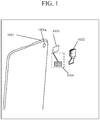
- FIG. 1 is a first schematic view showing configuration of a terminal device according to an exemplary embodiment. As shown in FIG. 1 , the terminal device at least includes:
- the terminal device at least includes: a first screen assembly 1001, an image collecting assembly 1002, a second screen assembly 1003, and a driving assembly 1004.
- the terminal device may be a wearable electronic apparatus and a mobile terminal
- the mobile terminal may include a mobile phone, a notebook, and a tablet, and the embodiment of the present disclosure is not limited thereto.
- the first screen assembly 1001 is configured to display an image.
- the first screen assembly 1001 may include a liquid crystal display and an Organic Light-Emitting Diode (OLED) display, which is not limited in the embodiment of the present disclosure.
- OLED Organic Light-Emitting Diode
- a shape and a size of the first opening 1001a of the first screen assembly 1001 are adapted to those of the image collecting assembly 1002, respectively.
- the shape of the first opening 1001a may be set according to the shape of the image collecting assembly 1002.
- the shape of the image collecting assembly 1002 is a circular
- the first opening 1001a may be set in a shape of a circle.
- the shape of the image collecting assembly 1002 is an ellipse
- the first opening 1001a may be set in a shape of an ellipse.
- the size of the first opening 1001a may also be set according to the size of the image collecting assembly 1002.
- the size of the image collecting assembly 1002 is set to be equal to that of the first opening 1001a.
- the image collecting assembly 1002 collects an image based on external light when the first opening 1001a is not shielded.
- the image collecting assembly 1002 includes a camera that is located on a surface where the first screen assembly 1001 of the terminal device is positioned.
- the driving assembly 1004 drives the second screen assembly 1003 to move between a first position and a second position.
- first position may be set as a starting position
- second position may be set as an ending position
- first position may be set as the ending position
- second position may be set as the starting position. That is to say, the second screen assembly 1003 can be gradually moved not only from the starting position to the ending position, but also from the ending position to the starting position.
- the second screen assembly 1003 is configured to display an image and cover the first opening 1001a.
- the size of the second screen assembly 1003 is required to match that of the first opening 1001a.
- the size of the second screen assembly 1003 may be set to be equal to or larger than that of the first opening 1001a, so as to cover the first opening 1001a.
- the first screen assembly 1001 when the first screen assembly 1001 is in the first position, the first opening 1001a is shielded, the second screen assembly 1003 is in a display state, and the image displayed by the second screen assembly 1003 which is an image that is not displayed by the first screen assembly 1001 at the first opening 1001a, forms a complete image together with the image displayed by the first screen assembly 1001.
- the image displayed by the first screen assembly 1001 and the image displayed by the second screen assembly 1003 constitute the complete image, which includes: the first screen assembly 1001 and the second screen assembly 1003 are configured to display different display areas of the same image.
- the first screen assembly 1001 displays a first area of the target image
- the second screen assembly 1003 displays a second area of the target image, wherein the first area is different from the second area.
- the second screen assembly 1003 is movable between the first position and the second position.
- the first opening 1001a is not shielded so that the image collecting assembly 1002 is capable of collecting an image.
- the second screen assembly 1003 is moved to the first position, the second screen assembly 1003 is in a display state, and the images displayed by the second screen assembly 1003 and the first screen assembly 1001 constitute the complete image.
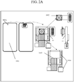
- FIG. 2A and FIG. 2B when the second screen assembly 1003 is in the second position, the second screen assembly 1003 is located behind the first screen assembly 1001, the first opening 1001a is not shielded, and the image collecting assembly 1002 is exposed by the first opening 1001a. At this time, the image can be collected by the exposed image collecting assembly 1002 so that the image collecting assembly 1002 is exposed to collect an image and then generate the image while taking a selfie.
- An assembly 10 in FIG. 2A and FIG.2B comprises the image collecting assembly 1002, the second screen assembly 1003, and the driving assembly 1004.
- An assembly 11 is a side view of the assembly 10.
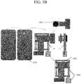
- FIG. 3A and FIG. 3B when the second screen assembly 1003 is in the first position, the second screen assembly 1003 is located between the first screen assembly 1001 and the image collecting assembly 1002 so that the second screen assembly 1003 covers the first opening 1001a, and is exposed through the first opening 1001a. At this time, the exposed second screen assembly 1003 is in a display state, and the image displayed thereof is an image that is not displayed by the first screen assembly 1001 at the first opening 1001a.
- An assembly 10 in FIG. 3A and FIG. 3B includes the image collecting assembly 1002, the second screen assembly 1003, and the driving assembly 1004.
- An assembly 11 is a side view of the assembly 10.
- the first screen assembly 1001 includes the first opening 1001a, and the image collecting assembly 1002 is located at a position on a side of the first opening 1001a toward inside of the terminal device so as to collect an image from external light through the first opening 1001a.
- the first opening 1001a in the embodiment of the present disclosure is capable of both providing external light for the image collecting assembly 1002 to collect images and being shielded by the second screen assembly 1003 when it is not required to collect the images. Therefore, it is not necessary for the embodiment of the present disclosure to consider a size of the first opening 1001a occupying a display surface of the first screen assembly 1001, thereby reducing difficulties in dimension designing and manufacturing of the image collecting assembly 1002, while improving quality of an image and meeting aesthetic needs of users.
- the image collecting assembly 1002 in the embodiment of the present disclosure is capable of collecting an image from the external light through the first opening 1001a when taking the selfie, and realizing that the second screen assembly 1003 covers the first opening 1001a and displays the image that is just not displayed by the screen assembly 1001 at the first opening 1001a when it is not required to collect the image.
- the image collecting assembly 1002 smoothly complete an image collection without specifically occupying a display area of the terminal device, thereby improving a screen-to-body ratio
- the image displayed by the first screen assembly 1001 can be combined with the image displayed by the second screen assembly 1003 to provide a complete image display, thereby reducing a probability of incomplete display and achieving a visual effect of full-screen display.
- an image collecting assembly 1002 is configured as a pop-up image collecting assembly. When it is required for the image collecting assembly 1002 to collect an image, the image collecting assembly 1002 is driven to move outside of the terminal device. When it is not required for the image collecting assembly 1002 to collect an image, the image collecting assembly 1002 is driven to move inside of the terminal device from outside thereof.
- the image collecting assembly 1002 in the embodiment of the present disclosure is not always moved to outside of the terminal device, but is normally located inside of the terminal device together with other assemblies such as the second screen assembly 1003 and the driving assembly 1004, etc. Therefore, by implementing the embodiments of the present disclosure, probability of dust and water entering the terminal device may be reduced, thereby improving anti-dust and waterproof level of the terminal device. At the same time, a problem of poor reliability caused by falling of the image collecting assembly 1002 being located outside the terminal device is resolved, thereby improving the reliability of the terminal device.
- FIG. 6 is a ninth schematic view showing configuration of a terminal device according to an exemplary embodiment.
- the driving assembly 1004 includes:
- the motor 1004b is capable of generating a rotational force in two opposite directions.
- the motor 1004b may be a DC motor, an asynchronous motor, or a synchronous motor, which is not limited in the embodiment of the present disclosure.
- the rotation assembly 1004a can be rotated in two opposite directions about the axis by means of the rotational force generated by the motor 1004b, thereby enabling the second screen assembly 1003 to move between the first position and the second position.
- the rotation assembly 1004a rotates toward a first direction to drive the second screen assembly 1003 to move from the first position to the second position; when not collecting the image, the rotation assembly 1004a rotates toward a second direction opposite to the first direction, to drive the second screen assembly 1003 to move from the second position to the first position.
- the terminal device may further include:
- the terminal device may further include:
- the terminal device may include a casing in a shape of rectangle; and both the first stop module 1006a and the second stop module 1006b are disposed in the casing and parallel to a short side of the casing.
- the terminal device may include a casing in a shape of rectangle; the second screen assembly 1003 is located within the casing; and the driving assembly 1004 is configured to drive the second screen assembly 1003 to move in a direction along a long side of the casing.
- the terminal device may further include: a guiding assembly 1007 fixedly coupled to the movement path stop assembly 1006 for guiding the second screen assembly 1003 to move between the first position and the second position along a setting direction of the guiding assembly 1007.
- the terminal device may further include:
- the second screen assembly 1003 is movable between the first position and the second position.
- the image collecting assembly 1002 smoothly complete an image collection without specifically occupying a display area of the terminal device.
- the first opening 1001a is shielded by the second screen assembly 1003 when it is required to normally display so as to achieve a visual effect of full-screen display.
- the terminal device may further include:
- the flexible circuit board 1009 has a characteristic of good bending property.
- the flexible circuit board 1009 can be bent from a first state to a second state. That is, the flexible circuit board 1009 can change current bending state according to current position of the second screen assembly 1003 to meet different needs, so as to provide more flexibility for designing the elements on the printed circuit board.
- the terminal device may further include: a transparent assembly covering a display surface of the first screen assembly 1001, through which the first opening 1001a can be shown.
- the transparent assembly may be an assembly formed of glass material.
- FIG. 11 is a block diagram of a terminal device 800, according to an exemplary embodiment.
- the terminal device 800 may be a mobile phone, a computer, a digital broadcast terminal, a messaging apparatus, a game console, a tablet apparatus, a medical apparatus, a fitness apparatus, a personal digital assistant, and the like.
- the terminal device 800 may comprise one or more of the following components: a processing component 802, a memory 804, a power component 806, a multimedia component 808, an audio component 810, an input/output (I/O) interface 812, a sensor component 814, and a communication component 816.
- the processing component 802 typically controls overall operation of terminal device 800, such as operations associated with display, telephone calls, data communications, camera operations, and recording operations.
- the processing component 802 may comprise one or more processors 820 to execute instructions to perform all or part of the steps in the above described methods.
- the processing component 802 may include one or more modules which facilitate the interaction between the processing component 802 and other components.
- the processing component 802 may include a multimedia module to facilitate interaction between the multimedia component 808 and the processing component 802.
- the memory 804 is configured to store various types of data to support operations at the terminal device 800. Examples of such data include instructions for any application or method operating on the terminal device 800, contact data, phone book data, messages, pictures, videos, and the like.
- the memory 804 may be implemented by any type of volatile or non-volatile storage apparatus, or a combination thereof, such as a static random access memory (SRAM), an electrically erasable programmable read only memory (EEPROM), an erasable programmable read only memory (EPROM), a programmable read only memory (PROM), a read only memory (ROM), a magnetic memory, a flash memory, a disk or an optical disk.
- SRAM static random access memory
- EEPROM electrically erasable programmable read only memory
- EPROM erasable programmable read only memory
- PROM programmable read only memory
- ROM read only memory
- magnetic memory a magnetic memory
- flash memory a flash memory
- disk or an optical disk an optical disk.
- the power component 806 provides power to various components of the terminal device 800.
- the power component 806 may comprise a power management system, one or more power sources, and other components associated with the generation, management, and distribution of power for terminal device 800.
- the multimedia component 808 includes a screen that provides an output interface between the terminal device 800 and a user.
- the screen may include a liquid crystal display (LCD) and a touch panel (TP). If the screen includes a touch panel, the screen may be implemented as a touch screen to receive input signals from the user.
- the touch panel includes one or more touch sensors to sense touches, slides, and gestures on the touch panel. The touch sensor may sense not only a boundary of a touch or a sliding action, but also duration and pressure associated with the touch or sliding action.
- the multimedia component 808 includes a front camera and/or a rear camera. The front camera and the rear camera may receive an external multimedia datum while the terminal device 800 is in an operation mode, such as a photographing mode or a video mode. Each of the front camera and the rear camera may be a fixed optical lens system or have focus and optical zoom capability.
- the audio component 810 is configured to output and/or input an audio signal.
- the audio component 810 includes a microphone (MIC) that is configured to receive an external audio signal when the terminal device 800 is in an operation mode, such as a call mode, a recording mode, and a voice recognition mode.
- the received audio signal may be further stored in the memory 804 or transmitted via the communication component 816.
- the audio component 810 further includes a speaker for outputting an audio signal.
- the I/O interface 812 provides an interface between the processing component 802 and a peripheral interface module, which may be a keyboard, a click wheel, buttons, or the like. These buttons may include, but are not limited to, a home button, a volume button, a start button, and a lock button.
- the sensor component 814 includes one or more sensors for providing the terminal device 800 with a status assessment in various aspects.
- the sensor component 814 may detect an on/off state of the terminal device 800, a relative positioning of components, such as the display and the keypad of the terminal device 800, and the sensor component 814 may also detect change of a position of the terminal device 800 or an component of the terminal device 800, presence or absence of contacting of the user with the terminal device 800, an orientation or acceleration/deceleration of the terminal device 800, and temperature change of the terminal device 800.
- the sensor component 814 may include a proximity sensor configured to detect presence of nearby objects without any physical contact.
- the sensor component 814 may also include an optical sensor, such as a CMOS or CCD image sensor, for use in imaging applications.
- the sensor component 814 may also include an accelerometer sensor, a gyroscope sensor, a magnetic sensor, a pressure sensor, or a temperature sensor.
- the communication component 816 is configured to facilitate wired or wireless communication between the terminal device 800 and other apparatus.
- the terminal device 800 is capable of accessing a wireless network based on a communication standard such as Wi-Fi, 2G or 3G, or a combination thereof.
- the communication component 816 receives broadcast signals or broadcast associated information from an external broadcast management system via a broadcast channel.
- the communication component 816 further includes a near field communication (NFC) module to facilitate short range communication.
- the NFC module may be implemented based on radio frequency identification (RFID) technology, infrared data association (IrDA) technology, ultra-wideband (UWB) technology, Bluetooth (BT) technology, and other technologies.
- RFID radio frequency identification
- IrDA infrared data association
- UWB ultra-wideband
- Bluetooth Bluetooth
- the terminal device 800 may be implemented by one or more application specific integrated circuits (ASICs), digital signal processors (DSPs), digital signal processing devices (DSPDs), programmable logic devices (PLDs), A gated arrays (FPGAs), controllers, microcontroller, microprocessors, or other electronic components, for performing the above methods.
- ASICs application specific integrated circuits
- DSPs digital signal processors
- DSPDs digital signal processing devices
- PLDs programmable logic devices
- FPGAs A gated arrays
- controllers microcontroller, microprocessors, or other electronic components, for performing the above methods.
- non-transitory computer-readable storage medium comprising instructions, such as included in the memory 804, executable by the processor 820 in the terminal device 800, for performing the above-described methods.
- the non-transitory computer-readable storage medium may be a ROM, a random access memory (RAM), a CD-ROM, a magnetic tape, a floppy disk, an optical data storage apparatus,, and the like.
Landscapes
- Engineering & Computer Science (AREA)
- Signal Processing (AREA)
- Computer Hardware Design (AREA)
- Theoretical Computer Science (AREA)
- Multimedia (AREA)
- Human Computer Interaction (AREA)
- Physics & Mathematics (AREA)
- General Engineering & Computer Science (AREA)
- General Physics & Mathematics (AREA)
- Telephone Set Structure (AREA)
- Devices For Indicating Variable Information By Combining Individual Elements (AREA)
Abstract
Description
- The present disclosure generally relates generally to technology fields of electronic apparatuses, and more specifically to a terminal device.
- With development of terminal technology and popularity of a smart terminal device, it is becoming a trend to dispose a camera for taking a selfie on the terminal device. However, the camera disposed on the existing terminal device occupies a certain space of a screen, which reduces a screen-to-body ratio of the terminal device. As a result, display effect of the terminal device is restricted and user experience of it is affected.
- The present disclosure is directed to provide a terminal device.
- According to an aspect of the embodiments of the present disclosure, there is provided a terminal device, comprising at least:
- a first screen assembly configured to display an image, and having a first opening;
- an image collecting assembly, disposed under the first screen assembly, and configured to collect an image based on external light when the first opening is not shielded;
- a second screen assembly configured to display an image and covering the first opening, and movably disposed between the first screen assembly and the image collecting assembly; and
- a driving assembly configured to drive the second screen assembly to move between a first position and a second position,
- wherein when the second screen assembly is in the first position and the first opening is shielded, the second screen assembly is in a display state and displays an image which is not displayed at the first opening in the first screen assembly, thereby forming a complete image with the image displayed by the first screen assembly; and
- wherein when the second screen assembly is moved to the second position, the first opening is not shielded, thereby that the image collecting assembly is capable of collecting an image.
- In an embodiment, the driving assembly comprises:
- a motor;
- a rotation assembly coupled to the motor and configured to rotate about a rotational axis to drive the second screen assembly to move between the first position and the second position by means of the motor.
- In an embodiment, the terminal device further includes:
- a first connection slot connected to the second screen assembly;
- wherein the rotation assembly is configured to pass through the first connection slot, and drive the second screen assembly to move through the first connection slot.
- In an embodiment, the terminal device further comprises:
- a movement path stop assembly, having a first stop module and a second stop module disposed opposite to the first stop module, wherein the second screen assembly is located at the first position when it is in contact with the first stop module, and the second screen assembly is located at the second position when it is in contact with the second stop module;
- a rotation assembly, located on the movement path stop assembly, and capable of driving the second screen assembly to move between the first stop module and the second stop module by rotation thereof relative to the movement path stop assembly.
- In an embodiment, the terminal device further comprises:
a guiding assembly fixedly coupled to the movement path stop assembly for guiding the second screen assembly to move between the first position and the second position along a setting direction of the guiding assembly. - In an embodiment, the terminal device further comprises:
- a second connection slot connected to the second screen assembly;
- wherein the guiding assembly is configured to pass through the second connection slot to guide the second screen assembly to move in the setting direction of the guiding assembly.
- In an embodiment, the terminal device further comprises:
- a printed circuit board;
- a flexible circuit board connected to the second screen assembly and parallel to the drive assembly;
- a connection assembly connected to the flexible circuit board and the printed circuit board respectively, for outputting control signals of the printed circuit board to the flexible circuit board;
- wherein the flexible circuit board is configured to control the image displayed by the second screen assembly as the image that is not displayed by the first screen assembly at the first opening, based on the control signals.
- In one embodiment, the terminal device the terminal device comprises a casing in a shape of rectangle;
wherein the second screen assembly is located within the casing;
wherein the driving assembly is configured to drive the second screen assembly to move in a direction along a long side of the casing. - In one embodiment, the terminal device comprises a casing in a shape of rectangle;
wherein both the first stop module and the second stop module are disposed in the casing and parallel to a short side of the casing. - In an embodiment, the terminal device further comprises:
a transparent assembly covering a display surface of the first screen assembly, through which the first opening can be shown. - The technical solutions provided by the embodiments of the present disclosure may include the following beneficial effects:
When it is required for the image collecting assembly to collect an image, the second screen assembly is driven to move to the second position, and the image collecting assembly collects an image through the first opening, so that it is realized that the image collecting assembly smoothly complete an image collection without specifically occupying a display area of the terminal device, which increases a screen-to-body ratio and improves user experience. At the same time, when it is not required for the image collecting assembly to generate an image, the second screen assembly is driven to move to the first position, and the image displayed by the second screen assembly and the image displayed by the first screen assembly constitute a complete image. As a result, by adjusting position of the second screen assembly, on the one hand, when it is required for the user to take a selfie, the image collecting assembly may be exposed to realize the selfie, and on the other hand, when the user needs a normal display, the second screen assembly may be used to make up the first opening, so as to achieve visually a full-screen display. - It should be appreciated that the above general description and the following detailed description are intended to be illustrative and not restrictive.
- The accompanying drawings, which are incorporated in and constitute a part of this specification, illustrate embodiments consistent with the present disclosure and, together with the description, serve to explain the principles of the present disclosure.
-
FIG. 1 is a first schematic view showing configuration of a terminal device according to an exemplary embodiment. -
FIG. 2A is a second schematic view showing configuration of a terminal device according to an exemplary embodiment. -
FIG. 2B is a third schematic view showing configuration of a terminal device according to an exemplary embodiment. -
FIG. 3A is a fourth schematic view showing configuration of a terminal device according to an exemplary embodiment. -
FIG. 3B is a fifth schematic view showing configuration of a terminal device according to an exemplary embodiment. -
FIG. 4 is a sixth schematic view showing configuration of a terminal device according to an exemplary embodiment. -
FIG. 5A is a seventh schematic view showing configuration of a terminal device according to an exemplary embodiment. -
FIG. 5B is an eighth schematic view showing configuration of a terminal device according to an exemplary embodiment. -
FIG. 6 is a ninth schematic view showing configuration of a terminal device according to an exemplary embodiment. -
FIG. 7 is a tenth schematic view showing configuration of a terminal device according to an exemplary embodiment. -
FIG. 8 is an eleventh schematic view showing configuration of a terminal device according to an exemplary embodiment. -
FIG. 9 is a twelfth schematic view showing configuration of a terminal device according to an exemplary embodiment. -
FIG. 10 is a thirteenth schematic view showing configuration of a terminal device according to an exemplary embodiment. -
FIG. 11 is a fourteenth schematic view showing configuration of a terminal device according to an exemplary embodiment. - Reference will now be made in detail to exemplary embodiments, examples of which are illustrated in the accompanying drawings. The following description refers to the accompanying drawings in which the same numbers in different drawings represent the same or similar elements unless otherwise represented. The implementations set forth in the following description of exemplary embodiments do not represent all implementations consistent with the present disclosure. Instead, they are merely examples of apparatuses and methods consistent with aspects related to the present disclosure as recited in the appended claims.
-
FIG. 1 is a first schematic view showing configuration of a terminal device according to an exemplary embodiment. As shown inFIG. 1 , the terminal device at least includes: - a
first screen assembly 1001 configured to display an image, wherein thefirst screen assembly 1001 includes afirst opening 1001a; - an
image collecting assembly 1002, disposed under thefirst screen assembly 1001, and configured to collect an image based on external light when thefirst opening 1001a is not shielded; - a
second screen assembly 1003 configured to display an image and covering thefirst opening 1001a, and movably disposed between thefirst screen assembly 1001 and theimage collecting assembly 1002; and - a driving
assembly 1004 configured to drive thesecond screen assembly 1003 to move between a first position and a second position; - wherein when the
second screen assembly 1003 is in the first position, thefirst opening 1001a is shielded and thesecond screen assembly 1003 is in a display state displaying an image which is not displayed at thefirst opening 1001a in thefirst screen assembly 1001, thereby forming a complete image together with an image displayed by thefirst screen assembly 1001; and wherein when thesecond screen assembly 1003 is moved to the second position, thefirst opening 1001a is not shielded, thereby theimage collecting assembly 1002 is capable of collecting an image. - In the embodiment of the present disclosure, the terminal device at least includes:
afirst screen assembly 1001, animage collecting assembly 1002, asecond screen assembly 1003, and a drivingassembly 1004. - Illustratively, the terminal device may be a wearable electronic apparatus and a mobile terminal, and the mobile terminal may include a mobile phone, a notebook, and a tablet, and the embodiment of the present disclosure is not limited thereto.
- In the embodiment of the present disclosure, the
first screen assembly 1001 is configured to display an image. - Illustratively, the
first screen assembly 1001 may include a liquid crystal display and an Organic Light-Emitting Diode (OLED) display, which is not limited in the embodiment of the present disclosure. - In the embodiment of the present disclosure, a shape and a size of the
first opening 1001a of thefirst screen assembly 1001 are adapted to those of theimage collecting assembly 1002, respectively. - It is required to note that the shape of the
first opening 1001a may be set according to the shape of theimage collecting assembly 1002. For example, when the shape of theimage collecting assembly 1002 is a circular, thefirst opening 1001a may be set in a shape of a circle. When the shape of theimage collecting assembly 1002 is an ellipse, thefirst opening 1001a may be set in a shape of an ellipse. - Certainly, the size of the
first opening 1001a may also be set according to the size of theimage collecting assembly 1002. For example, the size of theimage collecting assembly 1002 is set to be equal to that of thefirst opening 1001a. - In the embodiment of the present disclosure, the
image collecting assembly 1002 collects an image based on external light when thefirst opening 1001a is not shielded. - Illustratively, the
image collecting assembly 1002 includes a camera that is located on a surface where thefirst screen assembly 1001 of the terminal device is positioned. - In the embodiment of the present disclosure, the driving
assembly 1004 drives thesecond screen assembly 1003 to move between a first position and a second position. - It is required to note that the first position may be set as a starting position, and the second position may be set as an ending position. Alternatively, the first position may be set as the ending position, and the second position may be set as the starting position. That is to say, the
second screen assembly 1003 can be gradually moved not only from the starting position to the ending position, but also from the ending position to the starting position. - In the embodiment of the present disclosure, the
second screen assembly 1003 is configured to display an image and cover thefirst opening 1001a. - It is required to note that the size of the
second screen assembly 1003 is required to match that of thefirst opening 1001a. For example, the size of thesecond screen assembly 1003 may be set to be equal to or larger than that of thefirst opening 1001a, so as to cover thefirst opening 1001a. - In the embodiment of the present disclosure, when the
first screen assembly 1001 is in the first position, thefirst opening 1001a is shielded, thesecond screen assembly 1003 is in a display state, and the image displayed by thesecond screen assembly 1003 which is an image that is not displayed by thefirst screen assembly 1001 at thefirst opening 1001a, forms a complete image together with the image displayed by thefirst screen assembly 1001. - It is required to note that the image displayed by the
first screen assembly 1001 and the image displayed by thesecond screen assembly 1003 constitute the complete image, which includes: thefirst screen assembly 1001 and thesecond screen assembly 1003 are configured to display different display areas of the same image. - Illustratively, when displaying a target image, the
first screen assembly 1001 displays a first area of the target image, and thesecond screen assembly 1003 displays a second area of the target image, wherein the first area is different from the second area. - In the embodiment of the present disclosure, the
second screen assembly 1003 is movable between the first position and the second position. When thesecond screen assembly 1003 is moved to the second position, thefirst opening 1001a is not shielded so that theimage collecting assembly 1002 is capable of collecting an image. When thesecond screen assembly 1003 is moved to the first position, thesecond screen assembly 1003 is in a display state, and the images displayed by thesecond screen assembly 1003 and thefirst screen assembly 1001 constitute the complete image. - Illustratively, as shown in
FIG. 2A andFIG. 2B , when thesecond screen assembly 1003 is in the second position, thesecond screen assembly 1003 is located behind thefirst screen assembly 1001, thefirst opening 1001a is not shielded, and theimage collecting assembly 1002 is exposed by thefirst opening 1001a. At this time, the image can be collected by the exposedimage collecting assembly 1002 so that theimage collecting assembly 1002 is exposed to collect an image and then generate the image while taking a selfie. Anassembly 10 inFIG. 2A andFIG.2B comprises theimage collecting assembly 1002, thesecond screen assembly 1003, and the drivingassembly 1004. Anassembly 11 is a side view of theassembly 10. - As shown in
FIG. 3A andFIG. 3B , when thesecond screen assembly 1003 is in the first position, thesecond screen assembly 1003 is located between thefirst screen assembly 1001 and theimage collecting assembly 1002 so that thesecond screen assembly 1003 covers thefirst opening 1001a, and is exposed through thefirst opening 1001a. At this time, the exposedsecond screen assembly 1003 is in a display state, and the image displayed thereof is an image that is not displayed by thefirst screen assembly 1001 at thefirst opening 1001a. Anassembly 10 inFIG. 3A andFIG. 3B includes theimage collecting assembly 1002, thesecond screen assembly 1003, and the drivingassembly 1004. Anassembly 11 is a side view of theassembly 10. - During designing of an
image collecting assembly 1002 of the terminal device, as shown inFIG. 4 , thefirst screen assembly 1001 includes thefirst opening 1001a, and theimage collecting assembly 1002 is located at a position on a side of thefirst opening 1001a toward inside of the terminal device so as to collect an image from external light through thefirst opening 1001a. - With respect to the terminal device of
FIG. 4 , since thefirst opening 1001a in the embodiment of the present disclosure is capable of both providing external light for theimage collecting assembly 1002 to collect images and being shielded by thesecond screen assembly 1003 when it is not required to collect the images. Therefore, it is not necessary for the embodiment of the present disclosure to consider a size of thefirst opening 1001a occupying a display surface of thefirst screen assembly 1001, thereby reducing difficulties in dimension designing and manufacturing of theimage collecting assembly 1002, while improving quality of an image and meeting aesthetic needs of users. - In addition, the
image collecting assembly 1002 in the embodiment of the present disclosure is capable of collecting an image from the external light through thefirst opening 1001a when taking the selfie, and realizing that thesecond screen assembly 1003 covers thefirst opening 1001a and displays the image that is just not displayed by thescreen assembly 1001 at thefirst opening 1001a when it is not required to collect the image. Therefore, on one hand, it can be realized that theimage collecting assembly 1002 smoothly complete an image collection without specifically occupying a display area of the terminal device, thereby improving a screen-to-body ratio, and on the other hand, the image displayed by thefirst screen assembly 1001 can be combined with the image displayed by thesecond screen assembly 1003 to provide a complete image display, thereby reducing a probability of incomplete display and achieving a visual effect of full-screen display. - As shown in
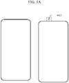
FIG.5A andFIG.5B , animage collecting assembly 1002 is configured as a pop-up image collecting assembly. When it is required for theimage collecting assembly 1002 to collect an image, theimage collecting assembly 1002 is driven to move outside of the terminal device. When it is not required for theimage collecting assembly 1002 to collect an image, theimage collecting assembly 1002 is driven to move inside of the terminal device from outside thereof. - With respect to
FIG. 5A andFIG. 5B , theimage collecting assembly 1002 in the embodiment of the present disclosure is not always moved to outside of the terminal device, but is normally located inside of the terminal device together with other assemblies such as thesecond screen assembly 1003 and the drivingassembly 1004, etc. Therefore, by implementing the embodiments of the present disclosure, probability of dust and water entering the terminal device may be reduced, thereby improving anti-dust and waterproof level of the terminal device. At the same time, a problem of poor reliability caused by falling of theimage collecting assembly 1002 being located outside the terminal device is resolved, thereby improving the reliability of the terminal device. - In an embodiment,
FIG. 6 is a ninth schematic view showing configuration of a terminal device according to an exemplary embodiment. As shown inFIG. 6 , the drivingassembly 1004 includes: - a
motor 1004b; - a
rotation assembly 1004a, coupled to themotor 1004b and rotating about a rotational axis to drive thesecond screen assembly 1003 to move between the first position and the second position by means of themotor 1004b. - In the embodiment of the present disclosure, the
motor 1004b is capable of generating a rotational force in two opposite directions. - Illustratively, the
motor 1004b may be a DC motor, an asynchronous motor, or a synchronous motor, which is not limited in the embodiment of the present disclosure. - In the embodiment of the present disclosure, the
rotation assembly 1004a can be rotated in two opposite directions about the axis by means of the rotational force generated by themotor 1004b, thereby enabling thesecond screen assembly 1003 to move between the first position and the second position. - It is required to note that when collecting the image, that is, taking a selfie, the
rotation assembly 1004a rotates toward a first direction to drive thesecond screen assembly 1003 to move from the first position to the second position; when not collecting the image, therotation assembly 1004a rotates toward a second direction opposite to the first direction, to drive thesecond screen assembly 1003 to move from the second position to the first position. - In an embodiment, as shown in
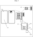
FIG. 7 , the terminal device may further include: - a
first connection slot 1005 connected to thesecond screen assembly 1003; - a
rotation assembly 1004a passing through thefirst connection slot 1005, and driving thesecond screen assembly 1003 to move through thefirst connection slot 1005. - It is required to note that when the
rotation assembly 1004a is rotated toward two opposite directions, a force acting on thefirst connection slot 1005 is generated. By this force, thesecond screen assembly 1003 connected to thefirst connection slot 1005 is movable between a position and a second position. - In an embodiment, as shown in
FIG. 8 , the terminal device may further include: - a movement path stop
assembly 1006, comprising afirst stop module 1006a and asecond stop module 1006b disposed opposite to thefirst stop module 1006a, wherein thesecond screen assembly 1003 is located at a first position when it is in contact with thefirst stop module 1006a, and thesecond screen assembly 1003 is located at a second position when it is in contact with thesecond stop module 1006b; - a
rotation assembly 1004a, located on the movement path stopassembly 1006, and capable of driving thesecond screen assembly 1003 to move between thefirst stop module 1006a and thesecond stop module 1006b by rotation thereof relative to the movement path stopassembly 1006. - In an embodiment as shown in
FIG. 8 , the terminal device may include a casing in a shape of rectangle; and
both thefirst stop module 1006a and thesecond stop module 1006b are disposed in the casing and parallel to a short side of the casing. - In an embodiment as shown in
FIG. 8 , the terminal device may include a casing in a shape of rectangle;
thesecond screen assembly 1003 is located within the casing; and
the drivingassembly 1004 is configured to drive thesecond screen assembly 1003 to move in a direction along a long side of the casing. - In an embodiment as shown in
FIG. 9 , the terminal device may further include:
a guidingassembly 1007 fixedly coupled to the movement path stopassembly 1006 for guiding thesecond screen assembly 1003 to move between the first position and the second position along a setting direction of the guidingassembly 1007. - In an embodiment as shown in
FIG. 9 , the terminal device may further include: - a
second connection slot 1008 connected to thesecond screen assembly 1003; - a guiding
assembly 1007 passing through thesecond connection slot 1008 to guide thesecond screen assembly 1003 to move in a setting direction of the guidingassembly 1007. - It could be appreciated that, by the cooperation of the guiding
assembly 1007 and therotation assembly 1004a, thesecond screen assembly 1003 is movable between the first position and the second position. As a result, it can be realized that theimage collecting assembly 1002 smoothly complete an image collection without specifically occupying a display area of the terminal device. Thefirst opening 1001a is shielded by thesecond screen assembly 1003 when it is required to normally display so as to achieve a visual effect of full-screen display. - In an embodiment, as shown in
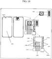
FIG. 10 , the terminal device may further include: - a printed circuit board;
- a
flexible circuit board 1009 connected to thesecond screen assembly 1003, and parallel to thedrive assembly 1004; - a
connection assembly 1010 connected to theflexible circuit board 1009 and the printed circuit board respectively, for outputting control signals of the printed circuit board to theflexible circuit board 1009; - wherein the
flexible circuit board 1009 is configured to control the image displayed by thesecond screen assembly 1003 as the image that is not displayed by thefirst screen assembly 1001 at thefirst opening 1001a, based on the control signals. - It is required to note that the
flexible circuit board 1009 has a characteristic of good bending property. When thesecond screen assembly 1003 is moved from the first position to the second position, theflexible circuit board 1009 can be bent from a first state to a second state. That is, theflexible circuit board 1009 can change current bending state according to current position of thesecond screen assembly 1003 to meet different needs, so as to provide more flexibility for designing the elements on the printed circuit board. - In an embodiment, the terminal device may further include:
a transparent assembly covering a display surface of thefirst screen assembly 1001, through which thefirst opening 1001a can be shown. - Illustratively, the transparent assembly may be an assembly formed of glass material.
- It could be understood that, by disposing the transparent assembly on the display surface, on the one hand, damage possibility of the first screen can be decreased, thereby extending usage time of the first screen assembly, and on the other hand, probability of the second screen assembly and the image collecting assembly in the terminal device exposed to environment can be reduced, which is beneficial to improve waterproof and dustproof effects of the terminal device.
- It is required to note that "first" and "second" in the embodiments of the present disclosure are merely for convenience of expression and distinction, without other specific meanings.
-
FIG. 11 is a block diagram of aterminal device 800, according to an exemplary embodiment. For example, theterminal device 800 may be a mobile phone, a computer, a digital broadcast terminal, a messaging apparatus, a game console, a tablet apparatus, a medical apparatus, a fitness apparatus, a personal digital assistant, and the like. - Referring to
FIG. 11 , theterminal device 800 may comprise one or more of the following components: aprocessing component 802, amemory 804, apower component 806, amultimedia component 808, anaudio component 810, an input/output (I/O)interface 812, asensor component 814, and acommunication component 816. - The
processing component 802 typically controls overall operation ofterminal device 800, such as operations associated with display, telephone calls, data communications, camera operations, and recording operations. Theprocessing component 802 may comprise one ormore processors 820 to execute instructions to perform all or part of the steps in the above described methods. Moreover, theprocessing component 802 may include one or more modules which facilitate the interaction between theprocessing component 802 and other components. For example, theprocessing component 802 may include a multimedia module to facilitate interaction between themultimedia component 808 and theprocessing component 802. - The
memory 804 is configured to store various types of data to support operations at theterminal device 800. Examples of such data include instructions for any application or method operating on theterminal device 800, contact data, phone book data, messages, pictures, videos, and the like. Thememory 804 may be implemented by any type of volatile or non-volatile storage apparatus, or a combination thereof, such as a static random access memory (SRAM), an electrically erasable programmable read only memory (EEPROM), an erasable programmable read only memory (EPROM), a programmable read only memory (PROM), a read only memory (ROM), a magnetic memory, a flash memory, a disk or an optical disk. - The
power component 806 provides power to various components of theterminal device 800. Thepower component 806 may comprise a power management system, one or more power sources, and other components associated with the generation, management, and distribution of power forterminal device 800. - The
multimedia component 808 includes a screen that provides an output interface between theterminal device 800 and a user. In some embodiments, the screen may include a liquid crystal display (LCD) and a touch panel (TP). If the screen includes a touch panel, the screen may be implemented as a touch screen to receive input signals from the user. The touch panel includes one or more touch sensors to sense touches, slides, and gestures on the touch panel. The touch sensor may sense not only a boundary of a touch or a sliding action, but also duration and pressure associated with the touch or sliding action. In some embodiments, themultimedia component 808 includes a front camera and/or a rear camera. The front camera and the rear camera may receive an external multimedia datum while theterminal device 800 is in an operation mode, such as a photographing mode or a video mode. Each of the front camera and the rear camera may be a fixed optical lens system or have focus and optical zoom capability. - The
audio component 810 is configured to output and/or input an audio signal. For example, theaudio component 810 includes a microphone (MIC) that is configured to receive an external audio signal when theterminal device 800 is in an operation mode, such as a call mode, a recording mode, and a voice recognition mode. The received audio signal may be further stored in thememory 804 or transmitted via thecommunication component 816. In some embodiments, theaudio component 810 further includes a speaker for outputting an audio signal. - The I/
O interface 812 provides an interface between theprocessing component 802 and a peripheral interface module, which may be a keyboard, a click wheel, buttons, or the like. These buttons may include, but are not limited to, a home button, a volume button, a start button, and a lock button. - The
sensor component 814 includes one or more sensors for providing theterminal device 800 with a status assessment in various aspects. For example, thesensor component 814 may detect an on/off state of theterminal device 800, a relative positioning of components, such as the display and the keypad of theterminal device 800, and thesensor component 814 may also detect change of a position of theterminal device 800 or an component of theterminal device 800, presence or absence of contacting of the user with theterminal device 800, an orientation or acceleration/deceleration of theterminal device 800, and temperature change of theterminal device 800. Thesensor component 814 may include a proximity sensor configured to detect presence of nearby objects without any physical contact. Thesensor component 814 may also include an optical sensor, such as a CMOS or CCD image sensor, for use in imaging applications. In some embodiments, thesensor component 814 may also include an accelerometer sensor, a gyroscope sensor, a magnetic sensor, a pressure sensor, or a temperature sensor. - The
communication component 816 is configured to facilitate wired or wireless communication between theterminal device 800 and other apparatus. Theterminal device 800 is capable of accessing a wireless network based on a communication standard such as Wi-Fi, 2G or 3G, or a combination thereof. In an exemplary embodiment, thecommunication component 816 receives broadcast signals or broadcast associated information from an external broadcast management system via a broadcast channel. In an exemplary embodiment, thecommunication component 816 further includes a near field communication (NFC) module to facilitate short range communication. For example, the NFC module may be implemented based on radio frequency identification (RFID) technology, infrared data association (IrDA) technology, ultra-wideband (UWB) technology, Bluetooth (BT) technology, and other technologies. - In an exemplary embodiment, the
terminal device 800 may be implemented by one or more application specific integrated circuits (ASICs), digital signal processors (DSPs), digital signal processing devices (DSPDs), programmable logic devices (PLDs), A gated arrays (FPGAs), controllers, microcontroller, microprocessors, or other electronic components, for performing the above methods. - In an exemplary embodiment, there is also provided a non-transitory computer-readable storage medium comprising instructions, such as included in the
memory 804, executable by theprocessor 820 in theterminal device 800, for performing the above-described methods. For example, the non-transitory computer-readable storage medium may be a ROM, a random access memory (RAM), a CD-ROM, a magnetic tape, a floppy disk, an optical data storage apparatus,, and the like.. - Other embodiments of the present disclosure will be apparent to those skilled in the art from consideration of the specification and practice of the present disclosure disclosed here. This application is intended to cover any variations, uses, or adaptations of the present disclosure following the general principles thereof and including such departures from the present disclosure as come within known or customary practice in the art. It is intended that the specification and examples be considered as exemplary only, with a true scope and spirit of the present disclosure being indicated by the following claims.
- It will be appreciated that the present disclosure is not limited to the exact construction that has been described above and illustrated in the accompanying drawings, and that various modifications and changes can be made without departing from the scope thereof. It is intended that the scope of the present disclosure only be limited by the appended claims.
Claims (10)
- A terminal device, at least comprising:a first screen assembly configured to display an image, and having a first opening;an image collecting assembly, disposed under the first screen assembly, and configured to collect an image based on external light when the first opening is not shielded;a second screen assembly configured to display an image and shield the first opening, and movably disposed between the first screen assembly and the image collecting assembly; anda driving assembly configured to drive the second screen assembly to move between a first position and a second position,wherein when the second screen assembly is in the first position and the first opening is shielded, the second screen assembly is in a display state and displays an image which is not displayed at the first opening in the first screen assembly, thereby forming a complete image with the image displayed by the first screen assembly; andwherein when the second screen assembly is moved to the second position, the first opening is not shielded, thereby the image collecting assembly is capable of collecting an image.
- The terminal device of claim 1, wherein the drive assembly comprises:a motor; anda rotation assembly coupled to the motor and configured to rotate about a rotational axis to drive the second screen assembly to move between the first position and the second position by means of the motor.
- The terminal device according to claim 2, further comprising:a first connection slot connected to the second screen assembly;wherein the rotation assembly is configured to pass through the first connection slot, and drive the second screen assembly to move through the first connection slot.
- The terminal device according to any one of claims 1 to 3, further comprising:a movement path stop assembly, having a first stop module and a second stop module disposed opposite to the first stop module, wherein the second screen assembly is located at the first position when it is in contact with the first stop module, and the second screen assembly is located at the second position when it is in contact with the second stop module;a rotation assembly, located on the movement path stop assembly, and capable of driving the second screen assembly to move between the first stop module and the second stop module by rotation thereof relative to the movement path stop assembly.
- The terminal device according to claim 4, further comprising:
a guiding assembly fixedly coupled to the movement path stop assembly for guiding the second screen assembly to move between the first position and the second position along a setting direction of the guiding assembly. - The terminal device according to claim 5, further comprising:a second connection slot connected to the second screen assembly;wherein the guiding assembly is configured to pass through the second connection slot to guide the second screen assembly to move in the setting direction of the guiding assembly.
- The terminal device of claim 1, further comprising:a printed circuit board;a flexible circuit board connected to the second screen assembly and parallel to the drive assembly;a connection assembly connected to the flexible circuit board and the printed circuit board respectively, for outputting control signals of the printed circuit board to the flexible circuit board;wherein the flexible circuit board is configured to control the image displayed by the second screen assembly as the image that is not displayed by the first screen assembly at the first opening, based on the control signals.
- The terminal device according to claim 1, further comprising a casing in a shape of rectangle;
wherein the second screen assembly is located within the casing;
wherein the driving assembly is configured to drive the second screen assembly to move in a direction along a long side of the casing. - The terminal device according to claim 4, further comprising a casing in a shape of rectangle;
wherein both the first stop module and the second stop module are disposed in the casing and parallel to a short side of the casing. - The terminal device of claim 1, further comprising:
a transparent assembly covering a display surface of the first screen assembly, through which the first opening can be shown.
Applications Claiming Priority (1)
| Application Number | Priority Date | Filing Date | Title |
|---|---|---|---|
| PCT/CN2019/099032 WO2021022404A1 (en) | 2019-08-02 | 2019-08-02 | Terminal device |
Publications (3)
| Publication Number | Publication Date |
|---|---|
| EP3800872A1 true EP3800872A1 (en) | 2021-04-07 |
| EP3800872A4 EP3800872A4 (en) | 2022-01-05 |
| EP3800872B1 EP3800872B1 (en) | 2025-10-01 |
Family
ID=74503267
Family Applications (1)
| Application Number | Title | Priority Date | Filing Date |
|---|---|---|---|
| EP19835225.4A Active EP3800872B1 (en) | 2019-08-02 | 2019-08-02 | Terminal device |
Country Status (4)
| Country | Link |
|---|---|
| US (1) | US11368569B2 (en) |
| EP (1) | EP3800872B1 (en) |
| CN (1) | CN112602311A (en) |
| WO (1) | WO2021022404A1 (en) |
Family Cites Families (16)
| Publication number | Priority date | Publication date | Assignee | Title |
|---|---|---|---|---|
| US20060109198A1 (en) * | 2004-11-23 | 2006-05-25 | Raymond Chow | Method and apparatus for using picture-in-picture data as an independent display |
| US7957768B2 (en) * | 2007-08-28 | 2011-06-07 | At&T Intellectual Property I, L.P. | Wireless communication device |
| CN103903213B (en) * | 2012-12-24 | 2018-04-27 | 联想(北京)有限公司 | A kind of image pickup method and electronic equipment |
| KR102131827B1 (en) * | 2013-12-03 | 2020-07-09 | 엘지전자 주식회사 | Mobile terminal and controlling method thereof |
| CN104238669B (en) * | 2014-09-04 | 2018-01-16 | 广东欧珀移动通信有限公司 | A kind of method, device and mobile terminal for controlling mobile terminal camera rotation |
| CN107771314A (en) * | 2015-06-15 | 2018-03-06 | 汤姆逊许可公司 | Apparatus and method for video scaling by selecting and tracking image regions |
| CN107330347B (en) * | 2017-05-25 | 2020-06-16 | 努比亚技术有限公司 | Display method, terminal and computer readable storage medium |
| EP3477922B1 (en) * | 2017-10-31 | 2020-11-04 | Guangdong Oppo Mobile Telecommunications Corp., Ltd. | Functional device and mobile terminal |
| CN108650441A (en) * | 2018-05-15 | 2018-10-12 | 珠海格力电器股份有限公司 | Camera mechanism, mobile multimedia device and mobile communication equipment |
| CN208724013U (en) * | 2018-05-25 | 2019-04-09 | 印象认知(北京)科技有限公司 | A kind of image capture device, electronic equipment and imaging device |
| CN109756594B (en) * | 2018-12-26 | 2020-08-18 | 维沃移动通信有限公司 | Method, terminal and storage medium for controlling screen |
| CN109729198B (en) * | 2018-12-28 | 2021-10-01 | 维沃移动通信有限公司 | an electronic device |
| CN109561183A (en) * | 2019-01-03 | 2019-04-02 | 京东方科技集团股份有限公司 | Display screen module and mobile terminal |
| CN109905501B (en) * | 2019-02-27 | 2021-02-12 | 维沃移动通信有限公司 | Mobile terminal and control method of display panel |
| CN109922243B (en) * | 2019-03-26 | 2021-01-26 | 田朋军 | Novel method for installing camera under screen |
| CN112181050B (en) * | 2019-07-01 | 2023-03-21 | 北京小米移动软件有限公司 | Terminal equipment and display method |
-
2019
- 2019-08-02 EP EP19835225.4A patent/EP3800872B1/en active Active
- 2019-08-02 US US16/764,152 patent/US11368569B2/en active Active
- 2019-08-02 CN CN201980002100.9A patent/CN112602311A/en active Pending
- 2019-08-02 WO PCT/CN2019/099032 patent/WO2021022404A1/en not_active Ceased
Also Published As
| Publication number | Publication date |
|---|---|
| EP3800872B1 (en) | 2025-10-01 |
| WO2021022404A1 (en) | 2021-02-11 |
| US20210409530A1 (en) | 2021-12-30 |
| CN112602311A (en) | 2021-04-02 |
| EP3800872A4 (en) | 2022-01-05 |
| US11368569B2 (en) | 2022-06-21 |
Similar Documents
| Publication | Publication Date | Title |
|---|---|---|
| EP3742711B1 (en) | Electronic device with a slidable flexible display for exposing sensors hidden behind the display | |
| KR101505681B1 (en) | A mobile terminal having a touch screen and image capturing method using the same | |
| US8564618B2 (en) | Adjusting the display orientation of an image on a mobile terminal | |
| JP5722847B2 (en) | Mobile terminal | |
| EP3139584A1 (en) | Camera-lens automatic pop-up device and terminal | |
| US9380433B2 (en) | Mobile terminal and control method thereof | |
| EP2824538A1 (en) | Electronic device and control method thereof | |
| CN110891191B (en) | Material selection method, device and storage medium | |
| CN209488641U (en) | Camera modules and electronics | |
| EP4040437A1 (en) | Method and apparatus for playing an animation, device and storage medium | |
| CN115002245B (en) | Rotation module and terminal equipment | |
| KR102403438B1 (en) | Terminal device and audio output method | |
| EP3995939A1 (en) | Method and device for touch operation, and storage medium | |
| US11598929B2 (en) | Terminal device, lens adjustment method and computer-readable storage medium | |
| EP3800872B1 (en) | Terminal device | |
| EP3629560A1 (en) | Full screen terminal, and operation control method and device based on full screen terminal | |
| CN110753197A (en) | A terminal device and audio output method | |
| CN210670329U (en) | Terminal equipment | |
| CN210123985U (en) | Mobile terminal | |
| KR101985505B1 (en) | Terminal and control method thereof | |
| CN210670330U (en) | a terminal device | |
| CN113190103A (en) | Terminal device, motion detection method and device of image acquisition module and storage medium | |
| KR101709503B1 (en) | Mobile terminal and image display method | |
| CN109917851B (en) | Terminal and electronic equipment | |
| KR101615232B1 (en) | Mobile terminal and method for controlling using camera in mobile terminal |
Legal Events
| Date | Code | Title | Description |
|---|---|---|---|
| STAA | Information on the status of an ep patent application or granted ep patent |
Free format text: STATUS: UNKNOWN |
|
| STAA | Information on the status of an ep patent application or granted ep patent |
Free format text: STATUS: THE INTERNATIONAL PUBLICATION HAS BEEN MADE |
|
| PUAI | Public reference made under article 153(3) epc to a published international application that has entered the european phase |
Free format text: ORIGINAL CODE: 0009012 |
|
| STAA | Information on the status of an ep patent application or granted ep patent |
Free format text: STATUS: REQUEST FOR EXAMINATION WAS MADE |
|
| 17P | Request for examination filed |
Effective date: 20200120 |
|
| AK | Designated contracting states |
Kind code of ref document: A1 Designated state(s): AL AT BE BG CH CY CZ DE DK EE ES FI FR GB GR HR HU IE IS IT LI LT LU LV MC MK MT NL NO PL PT RO RS SE SI SK SM TR |
|
| AX | Request for extension of the european patent |
Extension state: BA ME |
|
| RIC1 | Information provided on ipc code assigned before grant |
Ipc: H04M 1/667 20060101ALI20210901BHEP Ipc: G06F 1/16 20060101ALI20210901BHEP Ipc: H04M 1/02 20060101AFI20210901BHEP |
|
| A4 | Supplementary search report drawn up and despatched |
Effective date: 20211208 |
|
| RIC1 | Information provided on ipc code assigned before grant |
Ipc: H04M 1/667 20060101ALI20211202BHEP Ipc: G06F 1/16 20060101ALI20211202BHEP Ipc: H04M 1/02 20060101AFI20211202BHEP |
|
| DAV | Request for validation of the european patent (deleted) | ||
| DAX | Request for extension of the european patent (deleted) | ||
| STAA | Information on the status of an ep patent application or granted ep patent |
Free format text: STATUS: EXAMINATION IS IN PROGRESS |
|
| 17Q | First examination report despatched |
Effective date: 20230323 |
|
| GRAP | Despatch of communication of intention to grant a patent |
Free format text: ORIGINAL CODE: EPIDOSNIGR1 |
|
| STAA | Information on the status of an ep patent application or granted ep patent |
Free format text: STATUS: GRANT OF PATENT IS INTENDED |
|
| INTG | Intention to grant announced |
Effective date: 20250318 |
|
| GRAS | Grant fee paid |
Free format text: ORIGINAL CODE: EPIDOSNIGR3 |
|
| GRAA | (expected) grant |
Free format text: ORIGINAL CODE: 0009210 |
|
| STAA | Information on the status of an ep patent application or granted ep patent |
Free format text: STATUS: THE PATENT HAS BEEN GRANTED |
|
| AK | Designated contracting states |
Kind code of ref document: B1 Designated state(s): AL AT BE BG CH CY CZ DE DK EE ES FI FR GB GR HR HU IE IS IT LI LT LU LV MC MK MT NL NO PL PT RO RS SE SI SK SM TR |
|
| REG | Reference to a national code |
Ref country code: GB Ref legal event code: FG4D Ref country code: CH Ref legal event code: F10 Free format text: ST27 STATUS EVENT CODE: U-0-0-F10-F00 (AS PROVIDED BY THE NATIONAL OFFICE) Effective date: 20251001 |
|
| REG | Reference to a national code |
Ref country code: IE Ref legal event code: FG4D |
|
| REG | Reference to a national code |
Ref country code: DE Ref legal event code: R096 Ref document number: 602019076442 Country of ref document: DE |
|
| REG | Reference to a national code |
Ref country code: NL Ref legal event code: MP Effective date: 20251001 |
|
| REG | Reference to a national code |
Ref country code: AT Ref legal event code: MK05 Ref document number: 1843783 Country of ref document: AT Kind code of ref document: T Effective date: 20251001 |
|
| PG25 | Lapsed in a contracting state [announced via postgrant information from national office to epo] |
Ref country code: NL Free format text: LAPSE BECAUSE OF FAILURE TO SUBMIT A TRANSLATION OF THE DESCRIPTION OR TO PAY THE FEE WITHIN THE PRESCRIBED TIME-LIMIT Effective date: 20251001 |
|
| PG25 | Lapsed in a contracting state [announced via postgrant information from national office to epo] |
Ref country code: ES Free format text: LAPSE BECAUSE OF FAILURE TO SUBMIT A TRANSLATION OF THE DESCRIPTION OR TO PAY THE FEE WITHIN THE PRESCRIBED TIME-LIMIT Effective date: 20251001 |
|
| REG | Reference to a national code |
Ref country code: LT Ref legal event code: MG9D |
|
| PG25 | Lapsed in a contracting state [announced via postgrant information from national office to epo] |
Ref country code: NO Free format text: LAPSE BECAUSE OF FAILURE TO SUBMIT A TRANSLATION OF THE DESCRIPTION OR TO PAY THE FEE WITHIN THE PRESCRIBED TIME-LIMIT Effective date: 20260101 |
|
| PG25 | Lapsed in a contracting state [announced via postgrant information from national office to epo] |
Ref country code: AT Free format text: LAPSE BECAUSE OF FAILURE TO SUBMIT A TRANSLATION OF THE DESCRIPTION OR TO PAY THE FEE WITHIN THE PRESCRIBED TIME-LIMIT Effective date: 20251001 Ref country code: HR Free format text: LAPSE BECAUSE OF FAILURE TO SUBMIT A TRANSLATION OF THE DESCRIPTION OR TO PAY THE FEE WITHIN THE PRESCRIBED TIME-LIMIT Effective date: 20251001 Ref country code: FI Free format text: LAPSE BECAUSE OF FAILURE TO SUBMIT A TRANSLATION OF THE DESCRIPTION OR TO PAY THE FEE WITHIN THE PRESCRIBED TIME-LIMIT Effective date: 20251001 |
|
| PG25 | Lapsed in a contracting state [announced via postgrant information from national office to epo] |
Ref country code: RS Free format text: LAPSE BECAUSE OF FAILURE TO SUBMIT A TRANSLATION OF THE DESCRIPTION OR TO PAY THE FEE WITHIN THE PRESCRIBED TIME-LIMIT Effective date: 20260101 |
|
| PG25 | Lapsed in a contracting state [announced via postgrant information from national office to epo] |
Ref country code: IS Free format text: LAPSE BECAUSE OF FAILURE TO SUBMIT A TRANSLATION OF THE DESCRIPTION OR TO PAY THE FEE WITHIN THE PRESCRIBED TIME-LIMIT Effective date: 20260201 |
|
| PG25 | Lapsed in a contracting state [announced via postgrant information from national office to epo] |
Ref country code: CZ Free format text: LAPSE BECAUSE OF FAILURE TO SUBMIT A TRANSLATION OF THE DESCRIPTION OR TO PAY THE FEE WITHIN THE PRESCRIBED TIME-LIMIT Effective date: 20251001 Ref country code: PT Free format text: LAPSE BECAUSE OF FAILURE TO SUBMIT A TRANSLATION OF THE DESCRIPTION OR TO PAY THE FEE WITHIN THE PRESCRIBED TIME-LIMIT Effective date: 20260202 |
|
| PG25 | Lapsed in a contracting state [announced via postgrant information from national office to epo] |
Ref country code: PL Free format text: LAPSE BECAUSE OF FAILURE TO SUBMIT A TRANSLATION OF THE DESCRIPTION OR TO PAY THE FEE WITHIN THE PRESCRIBED TIME-LIMIT Effective date: 20251001 |
|
| PG25 | Lapsed in a contracting state [announced via postgrant information from national office to epo] |
Ref country code: LV Free format text: LAPSE BECAUSE OF FAILURE TO SUBMIT A TRANSLATION OF THE DESCRIPTION OR TO PAY THE FEE WITHIN THE PRESCRIBED TIME-LIMIT Effective date: 20251001 |
|
| PG25 | Lapsed in a contracting state [announced via postgrant information from national office to epo] |
Ref country code: BG Free format text: LAPSE BECAUSE OF FAILURE TO SUBMIT A TRANSLATION OF THE DESCRIPTION OR TO PAY THE FEE WITHIN THE PRESCRIBED TIME-LIMIT Effective date: 20251001 |