EP3800859B1 - Electronic device for improving quality of call and operation method thereof - Google Patents
Electronic device for improving quality of call and operation method thereof Download PDFInfo
- Publication number
- EP3800859B1 EP3800859B1 EP20199908.3A EP20199908A EP3800859B1 EP 3800859 B1 EP3800859 B1 EP 3800859B1 EP 20199908 A EP20199908 A EP 20199908A EP 3800859 B1 EP3800859 B1 EP 3800859B1
- Authority
- EP
- European Patent Office
- Prior art keywords
- electronic device
- call connection
- various embodiments
- call
- external electronic
- Prior art date
- Legal status (The legal status is an assumption and is not a legal conclusion. Google has not performed a legal analysis and makes no representation as to the accuracy of the status listed.)
- Active
Links
- 238000000034 method Methods 0.000 title claims description 68
- 230000005540 biological transmission Effects 0.000 claims description 167
- 230000004044 response Effects 0.000 claims description 99
- 238000004891 communication Methods 0.000 claims description 88
- 238000012545 processing Methods 0.000 claims description 75
- 230000008569 process Effects 0.000 claims description 36
- 238000005070 sampling Methods 0.000 claims description 34
- 238000012790 confirmation Methods 0.000 claims description 31
- 230000001537 neural effect Effects 0.000 claims description 21
- 238000010586 diagram Methods 0.000 description 30
- 238000007781 pre-processing Methods 0.000 description 30
- 230000006870 function Effects 0.000 description 28
- 230000003213 activating effect Effects 0.000 description 23
- 238000012805 post-processing Methods 0.000 description 17
- 238000001914 filtration Methods 0.000 description 14
- 238000009877 rendering Methods 0.000 description 13
- 230000008859 change Effects 0.000 description 11
- 238000003860 storage Methods 0.000 description 9
- 230000006835 compression Effects 0.000 description 8
- 238000007906 compression Methods 0.000 description 8
- 230000010267 cellular communication Effects 0.000 description 5
- 230000015556 catabolic process Effects 0.000 description 4
- 238000004590 computer program Methods 0.000 description 4
- 238000006731 degradation reaction Methods 0.000 description 4
- 238000010801 machine learning Methods 0.000 description 4
- 238000000926 separation method Methods 0.000 description 3
- 238000012546 transfer Methods 0.000 description 3
- 241001465754 Metazoa Species 0.000 description 2
- 230000004913 activation Effects 0.000 description 2
- 238000013461 design Methods 0.000 description 2
- 230000000694 effects Effects 0.000 description 2
- 238000005516 engineering process Methods 0.000 description 2
- 230000007613 environmental effect Effects 0.000 description 2
- 238000009434 installation Methods 0.000 description 2
- 210000001747 pupil Anatomy 0.000 description 2
- 230000035807 sensation Effects 0.000 description 2
- 241000086550 Dinosauria Species 0.000 description 1
- 230000001133 acceleration Effects 0.000 description 1
- 238000013473 artificial intelligence Methods 0.000 description 1
- 239000008280 blood Substances 0.000 description 1
- 210000004369 blood Anatomy 0.000 description 1
- 230000001413 cellular effect Effects 0.000 description 1
- 239000004020 conductor Substances 0.000 description 1
- 238000013135 deep learning Methods 0.000 description 1
- 238000011161 development Methods 0.000 description 1
- 238000000605 extraction Methods 0.000 description 1
- 210000004709 eyebrow Anatomy 0.000 description 1
- 239000000446 fuel Substances 0.000 description 1
- 230000036541 health Effects 0.000 description 1
- 230000006872 improvement Effects 0.000 description 1
- 230000010354 integration Effects 0.000 description 1
- 230000003155 kinesthetic effect Effects 0.000 description 1
- 238000004519 manufacturing process Methods 0.000 description 1
- 230000002093 peripheral effect Effects 0.000 description 1
- 238000002360 preparation method Methods 0.000 description 1
- 238000003825 pressing Methods 0.000 description 1
- 230000005236 sound signal Effects 0.000 description 1
- 230000007480 spreading Effects 0.000 description 1
- 238000003892 spreading Methods 0.000 description 1
- 239000000758 substrate Substances 0.000 description 1
Images


Classifications
-
- H—ELECTRICITY
- H04—ELECTRIC COMMUNICATION TECHNIQUE
- H04N—PICTORIAL COMMUNICATION, e.g. TELEVISION
- H04N7/00—Television systems
- H04N7/14—Systems for two-way working
- H04N7/141—Systems for two-way working between two video terminals, e.g. videophone
- H04N7/147—Communication arrangements, e.g. identifying the communication as a video-communication, intermediate storage of the signals
-
- H—ELECTRICITY
- H04—ELECTRIC COMMUNICATION TECHNIQUE
- H04L—TRANSMISSION OF DIGITAL INFORMATION, e.g. TELEGRAPHIC COMMUNICATION
- H04L65/00—Network arrangements, protocols or services for supporting real-time applications in data packet communication
- H04L65/80—Responding to QoS
-
- H—ELECTRICITY
- H04—ELECTRIC COMMUNICATION TECHNIQUE
- H04L—TRANSMISSION OF DIGITAL INFORMATION, e.g. TELEGRAPHIC COMMUNICATION
- H04L65/00—Network arrangements, protocols or services for supporting real-time applications in data packet communication
- H04L65/1066—Session management
- H04L65/1069—Session establishment or de-establishment
-
- H—ELECTRICITY
- H04—ELECTRIC COMMUNICATION TECHNIQUE
- H04L—TRANSMISSION OF DIGITAL INFORMATION, e.g. TELEGRAPHIC COMMUNICATION
- H04L65/00—Network arrangements, protocols or services for supporting real-time applications in data packet communication
- H04L65/1066—Session management
-
- H—ELECTRICITY
- H04—ELECTRIC COMMUNICATION TECHNIQUE
- H04L—TRANSMISSION OF DIGITAL INFORMATION, e.g. TELEGRAPHIC COMMUNICATION
- H04L65/00—Network arrangements, protocols or services for supporting real-time applications in data packet communication
- H04L65/60—Network streaming of media packets
- H04L65/75—Media network packet handling
- H04L65/762—Media network packet handling at the source
-
- H—ELECTRICITY
- H04—ELECTRIC COMMUNICATION TECHNIQUE
- H04N—PICTORIAL COMMUNICATION, e.g. TELEVISION
- H04N7/00—Television systems
- H04N7/14—Systems for two-way working
- H04N7/141—Systems for two-way working between two video terminals, e.g. videophone
Landscapes
- Engineering & Computer Science (AREA)
- Multimedia (AREA)
- Signal Processing (AREA)
- Computer Networks & Wireless Communication (AREA)
- Business, Economics & Management (AREA)
- General Business, Economics & Management (AREA)
- Telephone Function (AREA)
- Mobile Radio Communication Systems (AREA)
Description
- Various embodiments relate to an electronic device and an operation method of the electronic device.
- Various electronic devices, such as smart phones, tablet PCs, portable multimedia players (PMPs), personal digital assistants (PDAs), laptop personal computers (PCs), and wearable devices are spreading.
- Recently, an electronic device may provide a voice call or a video call based on an IP multimedia subsystem (IMS) or a rich communication suite (RCS). While providing high-quality audio or images, the electronic device may process transmitted or received audio or image data to reduce the size of the audio or video data. Processing of the audio data or image data may be implemented in two steps. As a step of processing audio raw data generated using a microphone and image raw data generated using a camera, there may be a step of reducing the size of the data while minimizing and/or reducing, using a filter, quality degradation, and a step of reducing the size of the data while compressing the audio data or the image data.
- When a call is connected, a negotiation procedure based on a session description protocol (SDP) between electronic devices may be performed to configure an environment for the transmitted or received data, and a compression format for audio data or image data supportable between the electronic devices, and information of a sampling rate of the audio data or resolution of the image data may be exchanged during the negotiation procedure.
- In order to improve the quality of audio data or image data to be transmitted or received, pre-processing, using a filter, for the audio data or image data may be performed before the audio data or the image data is encoded. Recently, due to the development of technologies related to artificial intelligence and machine learning or deep learning, and the emergence of a neural processing unit, the quality improvement of audio data or image data, using a filter, is being studied.
- In an SDP-based negotiation procedure performed when a call is connected, data that is transmitted or received may not include information on the filter. Therefore, an electronic device may not know a filter that is used by an external electronic device, which is a counterpart of the call connection, to pre-process the audio data or the image data, and may not be able to quickly perform operations for improving an audio or image quality using the filter.
- Alternatively, after the call is connected, in a situation where information on the filter is exchanged, the call may be temporarily stopped when configurations of components of the electronic device are changed due to activation of the filter.
- Prior art
US2010027417 describes a method of sending a data flow including a video flow from a sending entity to a receiving entity over a telecommunications network, includes having the sending entity: obtain from the receiving entity information about a downlink bandwidth available for reception of the data flow at the receiving entity side; obtain information about an uplink bandwidth available for the transmission of the data flow at the sending entity side; set transmission parameters of the data flow to be sent to the receiving entity based on the information about the available downlink bandwidth and the available uplink bandwidth; and transmit the data flow in accordance with the set transmission parameters. - The above information is presented as background information only to assist with an understanding of the disclosure. No determination has been made, and no assertion is made, as to whether any of the above might be applicable as prior art with regard to the disclosure.
- The invention relates to an electronic device, as further defined in claim 1, and a method, as further defined in claim 10, for improving the quality of a call between two electronic devices.
- The above and other aspects, features and advantages of certain embodiments of the present disclosure will be more apparent from the following detailed description, taken in conjunction with the accompanying drawings, in which:
-
FIG. 1 is a block diagram illustrating an example electronic device in a network environment according to various embodiments; -
FIG. 2 is a block diagram illustrating an example program according to various embodiments; -
FIG. 3A is a block diagram illustrating an example in which a first electronic device and a second electronic device transmit or receive an audio content or an image content according to various embodiments; -
FIG. 3B is a block diagram illustrating an example in which a first electronic device and a second electronic device transmit or receive an audio content or an image content according to various embodiments; -
FIG. 4A is a block diagram illustrating an example electronic device according to various embodiments; -
FIG. 4B is a block diagram illustrating an example electronic device according to various embodiments; -
FIG 5 is a block diagram illustrating an example electronic device according to various embodiments; -
FIG. 6 is an operation flow diagram illustrating example operations of performing a call connection by the first electronic device and the second electronic device according to various embodiments; -
FIG. 7 is a diagram illustrating an example screen in which a configuration for content transmission or reception is performed, in a first electronic device and a second electronic device according to various embodiments; -
FIG. 8 is a flowchart illustrating an example operation method of an electronic device according to various embodiments; -
FIG. 9 is a flowchart illustrating an example operation method of an electronic device according to various embodiments; -
FIG. 10A is a block diagram illustrating an example electronic device according to various embodiments; -
FIG. 10B is a block diagram illustrating an example electronic device according to various embodiments; -
FIG. 11A is a diagram illustrating an example of extracting metadata from an acquired image, in an electronic device according to various embodiments; -
FIG. 11B is a diagram illustrating an example of rendering an image based on a model and metadata, in an electronic device according to various embodiments; -
FIG. 12 is an operation flow diagram illustrating example operations of performing a call connection by the first electronic device and the second electronic device according to various embodiments; -
FIG. 13 is a flowchart illustrating an example operation method of an electronic device according to various embodiments; and -
FIG. 14 is a flowchart illustrating an example operation method of an electronic device according to various embodiments. -
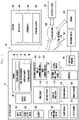
FIG. 1 is a block diagram illustrating an exampleelectronic device 101 in anetwork environment 100 according to various embodiments. Referring toFIG. 1 , theelectronic device 101 in thenetwork environment 100 may communicate with anelectronic device 102 via a first network 198 (e.g., a short-range wireless communication network), or anelectronic device 104 or aserver 108 via a second network 199 (e.g., a long-range wireless communication network). According to an embodiment, theelectronic device 101 may communicate with theelectronic device 104 via theserver 108. According to an embodiment, theelectronic device 101 may include aprocessor 120,memory 130, aninput device 150, asound output device 155, adisplay device 160, anaudio module 170, asensor module 176, aninterface 177, ahaptic module 179, acamera module 180, apower management module 188, abattery 189, acommunication module 190, a subscriber identification module (SIM) 196, or anantenna module 197. In some embodiments, at least one (e.g., thedisplay device 160 or the camera module 180) of the components may be omitted from theelectronic device 101, or one or more other components may be added in theelectronic device 101. In some embodiments, some of the components may be implemented as single integrated circuitry. For example, the sensor module 176 (e.g., a fingerprint sensor, an iris sensor, or an illuminance sensor) may be implemented as embedded in the display device 160 (e.g., a display). - The
processor 120 may execute, for example, software (e.g., a program 140) to control at least one other component (e.g., a hardware or software component) of theelectronic device 101 coupled with theprocessor 120, and may perform various data processing or computation. According to an example embodiment, as at least part of the data processing or computation, theprocessor 120 may load a command or data received from another component (e.g., thesensor module 176 or the communication module 190) involatile memory 132, process the command or the data stored in thevolatile memory 132, and store resulting data innon-volatile memory 134. According to an embodiment, theprocessor 120 may include a main processor 121 (e.g., a central processing unit (CPU) or an application processor (AP)), and an auxiliary processor 123 (e.g., a graphics processing unit (GPU), an image signal processor (ISP), a sensor hub processor, or a communication processor (CP)) that is operable independently from, or in conjunction with, themain processor 121. Additionally or alternatively, theauxiliary processor 123 may be adapted to consume less power than themain processor 121, or to be specific to a specified function. Theauxiliary processor 123 may be implemented as separate from, or as part of themain processor 121. - The
auxiliary processor 123 may control at least some of functions or states related to at least one component (e.g., thedisplay device 160, thesensor module 176, or the communication module 190) among the components of theelectronic device 101, instead of themain processor 121 while themain processor 121 is in an inactive (e.g., sleep) state, or together with themain processor 121 while themain processor 121 is in an active state (e.g., executing an application). According to an embodiment, the auxiliary processor 123 (e.g., an image signal processor or a communication processor) may be implemented as part of another component (e.g., thecamera module 180 or the communication module 190) functionally related to theauxiliary processor 123. - The
memory 130 may store various data used by at least one component (e.g., theprocessor 120 or the sensor module 176) of theelectronic device 101. The various data may include, for example, software (e.g., the program 140) and input data or output data for a command related thereto. Thememory 130 may include thevolatile memory 132 or thenon-volatile memory 134. - The
program 140 may be stored in thememory 130 as software, and may include, for example, an operating system (OS) 142,middleware 144, or anapplication 146. - The
input device 150 may receive a command or data to be used by other component (e.g., the processor 120) of theelectronic device 101, from the outside (e.g., a user) of theelectronic device 101. Theinput device 150 may include, for example, a microphone, a mouse, a keyboard, or a digital pen (e.g., a stylus pen). - The
sound output device 155 may output sound signals to the outside of theelectronic device 101. Thesound output device 155 may include, for example, a speaker or a receiver. The speaker may be used for general purposes, such as playing multimedia or playing record, and the receiver may be used for an incoming calls. According to an embodiment, the receiver may be implemented as separate from, or as part of the speaker. - The
display device 160 may visually provide information to the outside (e.g., a user) of theelectronic device 101. Thedisplay device 160 may include, for example, a display, a hologram device, or a projector and control circuitry to control a corresponding one of the display, hologram device, and projector. According to an embodiment, thedisplay device 160 may include touch circuitry adapted to detect a touch, or sensor circuitry (e.g., a pressure sensor) adapted to measure the intensity of force incurred by the touch. - The
audio module 170 may convert a sound into an electrical signal and vice versa. According to an embodiment, theaudio module 170 may obtain the sound via theinput device 150, or output the sound via thesound output device 155 or a headphone of an external electronic device (e.g., an electronic device 102) directly (e.g., wiredly) or wirelessly coupled with theelectronic device 101. - The
sensor module 176 may detect an operational state (e.g., power or temperature) of theelectronic device 101 or an environmental state (e.g., a state of a user) external to theelectronic device 101, and then generate an electrical signal or data value corresponding to the detected state. According to an embodiment, thesensor module 176 may include, for example, a gesture sensor, a gyro sensor, an atmospheric pressure sensor, a magnetic sensor, an acceleration sensor, a grip sensor, a proximity sensor, a color sensor, an infrared (IR) sensor, a biometric sensor, a temperature sensor, a humidity sensor, or an illuminance sensor. - The
interface 177 may support one or more specified protocols to be used for theelectronic device 101 to be coupled with the external electronic device (e.g., the electronic device 102) directly (e.g., wiredly) or wirelessly. According to an embodiment, theinterface 177 may include, for example, a high definition multimedia interface (HDMI), a universal serial bus (USB) interface, a secure digital (SD) card interface, or an audio interface. - A connecting
terminal 178 may include a connector via which theelectronic device 101 may be physically connected with the external electronic device (e.g., the electronic device 102). According to an embodiment, the connectingterminal 178 may include, for example, a HDMI connector, a USB connector, a SD card connector, or an audio connector (e.g., a headphone connector). - The
haptic module 179 may convert an electrical signal into a mechanical stimulus (e.g., a vibration or a movement) or electrical stimulus which may be recognized by a user via his tactile sensation or kinesthetic sensation. According to an embodiment, thehaptic module 179 may include, for example, a motor, a piezoelectric element, or an electric stimulator. - The
camera module 180 may capture a still image or moving images. According to an embodiment, thecamera module 180 may include one or more lenses, image sensors, image signal processors, or flashes. - The
power management module 188 may manage power supplied to theelectronic device 101. According to an example embodiment, thepower management module 188 may be implemented as at least part of, for example, a power management integrated circuit (PMIC). - The
battery 189 may supply power to at least one component of theelectronic device 101. According to an embodiment, thebattery 189 may include, for example, a primary cell which is not rechargeable, a secondary cell which is rechargeable, or a fuel cell. - The
communication module 190 may support establishing a direct (e.g., wired) communication channel or a wireless communication channel between theelectronic device 101 and the external electronic device (e.g., theelectronic device 102, theelectronic device 104, or the server 108) and performing communication via the established communication channel. Thecommunication module 190 may include one or more communication processors that are operable independently from the processor 120 (e.g., the application processor (AP)) and supports a direct (e.g., wired) communication or a wireless communication. According to an embodiment, thecommunication module 190 may include a wireless communication module 192 (e.g., a cellular communication module, a short-range wireless communication module, or a global navigation satellite system (GNSS) communication module) or a wired communication module 194 (e.g., a local area network (LAN) communication module or a power line communication (PLC) module). A corresponding one of these communication modules may communicate with the external electronic device via the first network 198 (e.g., a short-range communication network, such as Bluetooth™, wireless-fidelity (Wi-Fi) direct, or infrared data association (IrDA)) or the second network 199 (e.g., a long-range communication network, such as a cellular network, the Internet, or a computer network (e.g., LAN or wide area network (WAN)). These various types of communication modules may be implemented as a single component (e.g., a single chip), or may be implemented as multi components (e.g., multi chips) separate from each other. Thewireless communication module 192 may identify and authenticate theelectronic device 101 in a communication network, such as thefirst network 198 or thesecond network 199, using subscriber information (e.g., international mobile subscriber identity (IMSI)) stored in thesubscriber identification module 196. - The
antenna module 197 may transmit or receive a signal or power to or from the outside (e.g., the external electronic device) of theelectronic device 101. According to an embodiment, theantenna module 197 may include an antenna including a radiating element including a conductive material or a conductive pattern formed in or on a substrate (e.g., PCB). According to an embodiment, theantenna module 197 may include a plurality of antennas. In such a case, at least one antenna appropriate for a communication scheme used in the communication network, such as thefirst network 198 or thesecond network 199, may be selected, for example, by the communication module 190 (e.g., the wireless communication module 192) from the plurality of antennas. The signal or the power may then be transmitted or received between thecommunication module 190 and the external electronic device via the selected at least one antenna. According to an embodiment, another component (e.g., a radio frequency integrated circuit (RFIC)) other than the radiating element may be additionally formed as part of theantenna module 197. - At least some of the above-described components may be coupled mutually and communicate signals (e.g., commands or data) therebetween via an inter-peripheral communication scheme (e.g., a bus, general purpose input and output (GPIO), serial peripheral interface (SPI), or mobile industry processor interface (MIPI)).
- According to an embodiment, commands or data may be transmitted or received between the
electronic device 101 and the externalelectronic device 104 via theserver 108 coupled with thesecond network 199. Each of theelectronic devices electronic device 101. According to an embodiment, all or some of operations to be executed at theelectronic device 101 may be executed at one or more of the externalelectronic devices electronic device 101 should perform a function or a service automatically, or in response to a request from a user or another device, theelectronic device 101, instead of, or in addition to, executing the function or the service, may request the one or more external electronic devices to perform at least part of the function or the service. The one or more external electronic devices receiving the request may perform the at least part of the function or the service requested, or an additional function or an additional service related to the request, and transfer an outcome of the performing to theelectronic device 101. Theelectronic device 101 may provide the outcome, with or without further processing of the outcome, as at least part of a reply to the request. To that end, a cloud computing, distributed computing, or client-server computing technology may be used, for example. -
Fig. 2 is a block diagram 200 illustrating theprogram 140 according to various embodiments. According to an embodiment, theprogram 140 may include an operating system (OS) 142 to control one or more resources of theelectronic device 101,middleware 144, or anapplication 146 executable in theOS 142. TheOS 142 may include, for example, Android™, iOS™, Windows™, Symbian™, Tizen™, or Bada™. At least part of theprogram 140, for example, may be pre-loaded on theelectronic device 101 during manufacture, or may be downloaded from or updated by an external electronic device (e.g., theelectronic device - The
OS 142 may control management (e.g., allocating or deallocation) of one or more system resources (e.g., process, memory, or power source) of theelectronic device 101. TheOS 142, additionally or alternatively, may include one or more driver programs to drive other hardware devices of theelectronic device 101, for example, theinput device 150, thesound output device 155, thedisplay device 160, theaudio module 170, thesensor module 176, theinterface 177, thehaptic module 179, thecamera module 180, thepower management module 188, thebattery 189, thecommunication module 190, thesubscriber identification module 196, or theantenna module 197. - The
middleware 144 may provide various functions to theapplication 146 such that a function or information provided from one or more resources of theelectronic device 101 may be used by theapplication 146. Themiddleware 144 may include, for example, anapplication manager 201, awindow manager 203, amultimedia manager 205, aresource manager 207, apower manager 209, adatabase manager 211, apackage manager 213, aconnectivity manager 215, anotification manager 217, alocation manager 219, agraphic manager 221, asecurity manager 223, atelephony manager 225, or avoice recognition manager 227. - The
application manager 201, for example, may manage the life cycle of theapplication 146. Thewindow manager 203, for example, may manage one or more graphical user interface (GUI) resources that are used on a screen. Themultimedia manager 205, for example, may identify one or more formats to be used to play media files, and may encode or decode a corresponding one of the media files using a codec appropriate for a corresponding format selected from the one or more formats. Theresource manager 207, for example, may manage the source code of theapplication 146 or a memory space of the memory 130.Thepower manager 209, for example, may manage the capacity, temperature, or power of thebattery 189, and determine or provide related information to be used for the operation of theelectronic device 101 based at least in part on corresponding information of the capacity, temperature, or power of thebattery 189. According to an embodiment, thepower manager 209 may interwork with a basic input/output system (BIOS) (not shown) of theelectronic device 101. - The
database manager 211, for example, may generate, search, or change a database to be used by theapplication 146. Thepackage manager 213, for example, may manage installation or update of an application that is distributed in the form of a package file. Theconnectivity manager 215, for example, may manage a wireless connection or a direct connection between theelectronic device 101 and the external electronic device. Thenotification manager 217, for example, may provide a function to notify a user of an occurrence of a specified event (e.g., an incoming call, message, or alert). Thelocation manager 219, for example, may manage locational information on theelectronic device 101. Thegraphic manager 221, for example, may manage one or more graphic effects to be offered to a user or a user interface related to the one or more graphic effects. - The
security manager 223, for example, may provide system security or user authentication. Thetelephony manager 225, for example, may manage a voice call function or a video call function provided by theelectronic device 101. Thevoice recognition manager 227, for example, may transmit a user's voice data to theserver 108, and receive, from theserver 108, a command corresponding to a function to be executed on theelectronic device 101 based at least in part on the voice data, or text data converted based at least in part on the voice data. According to an embodiment, the middleware 244 may dynamically delete some existing components or add new components. According to an embodiment, at least part of themiddleware 144 may be included as part of theOS 142 or may be implemented as another software separate from theOS 142. - The
application 146 may include, for example, ahome 251,dialer 253, short message service (SMS)/multimedia messaging service (MMS) 255, instant message (IM) 257,browser 259,camera 261,alarm 263, contact 265,voice recognition 267,email 269,calendar 271,media player 273,album 275, watch 277, health 279 (e.g., for measuring the degree of workout or biometric information, such as blood sugar), or environmental information 281 (e.g., for measuring air pressure, humidity, or temperature information) application. According to an embodiment, theapplication 146 may further include an information exchanging application (not shown) that is capable of supporting information exchange between theelectronic device 101 and the external electronic device. The information exchange application, for example, may include a notification relay application adapted to transfer designated information (e.g., a call, message, or alert) to the external electronic device or a device management application adapted to manage the external electronic device. The notification relay application may transfer notification information corresponding to an occurrence of a specified event (e.g., receipt of an email) at another application (e.g., the email application 269) of theelectronic device 101 to the external electronic device. Additionally or alternatively, the notification relay application may receive notification information from the external electronic device and provide the notification information to a user of theelectronic device 101. - The device management application may control the power (e.g., turn-on or turn-off) or the function (e.g., adjustment of brightness, resolution, or focus) of the external electronic device or some component thereof (e.g., a display device or a camera module of the external electronic device). The device management application, additionally or alternatively, may support installation, delete, or update of an application running on the external electronic device.
-
FIG. 3A is a block diagram illustrating an example in which a first electronic device and a second electronic device transmit or receive an audio content or an image content according to various embodiments, andFIG. 3B is a block diagram illustrating an example in which a first electronic device and a second electronic device transmit or receive an audio content or an image content according to various embodiments. - According to various embodiments, a first electronic device 310 (e.g., the
electronic device 101 ofFIG. 1 ) and a second electronic device 320 (e.g., theelectronic device 101 ofFIG. 1 ) may perform a voice call and a video call based on various schemes (e.g., an IP multimedia subsystem (IMS) or a rich communication suite (RCS)). For the convenience of description, the firstelectronic device 310 may refer, for example, to a transmitting terminal, and the secondelectronic device 320 may refer, for example, to a receiving terminal. In order to determine a bit rate, a compression format (codec), or a quality (e.g., the quality may refer to a sampling rate in a case of audio data, and may refer to various variables representing the quality of audio data or image data, which include a resolution in a case of image data.) of audio data or image data transmitted or received when a call is connected, the firstelectronic device 310 and the secondelectronic device 320 may perform mutual negotiation using a scheme defined, for example, in a session description protocol (SDP). The firstelectronic device 310 and the secondelectronic device 320 may determine, via mutual negotiation, characteristics of audio data and/or image data to be transmitted, and may transmit or receive audio data or image data using the determined characteristics. Example embodiments of a mutual negotiation procedure for a call connection between the firstelectronic device 310 and the secondelectronic device 320 will be described in greater detail below with reference toFIG. 4 andFIG. 5 . -
FIG. 3A is a diagram illustrating an example of processing audio data between the firstelectronic device 310 and the secondelectronic device 320. - According to various embodiments, the first
electronic device 310 may include a microphone 311 (e.g., theinput device 150 ofFIG. 1 ) of the firstelectronic device 310, which receives a user' s voice, atransmission filter 313, anencoder 315 configured to encode audio data transmitted by thetransmission filter 313 to compress the audio data, and apacketizer 317 configured to convert the encoded audio data into audio packet data in a packet form. - According to various embodiments, the
transmission filter 313 may be configured to perform filtering on the user' s audio data transmitted by themicrophone 311. Thetransmission filter 313 may perform pre-processing (e.g., filtering) before the audio data generated by themicrophone 311 is input to theencoder 315, to generate audio data having a lower sampling rate (e.g., downscale) than a sampling rate of the audio data generated by themicrophone 311. Thetransmission filter 313 may generate audio data having a low sampling rate, and may transmit the generated audio data to theencoder 315, thereby reducing a size of the audio data to be transmitted to the secondelectronic device 320. - According to various embodiments, the
transmission filter 313 may be implemented using various algorithms, and may generate an audio content having a relatively low sampling rate while maintaining, as much as possible, a quality of an audio content generated by themicrophone 311. - According to various embodiments, the second
electronic device 320 may include adepacketizer 321 configured to convert, into encoded audio data, an audio data packet received via anetwork 330, adecoder 323 configured to decode the encoded audio data which has been converted by thedepacketizer 321, areception filter 325 configured to change a sampling rate of the decoded audio data, and a speaker 327 (e.g., theaudio output device 155 ofFIG. 1 ) configured to output audio data generated by the reception filter. - According to various embodiments, the
reception filter 325 may be configured to perform filtering on the decoded audio data generated by thedecoder 323. Thereception filter 325 may post-process (e.g., filtering) the decoded audio data, to generate audio data having a higher sampling rate (upscale) than a sampling rate corresponding to the decoded audio data. Thereception filter 325 may generate an audio content having a higher sampling rate than the sampling rate corresponding to the decoded audio data, and may transmit the generated audio content to thespeaker 327. - According to various embodiments, the
reception filter 325 may be implemented using various algorithms, and may generate an audio content having a quality that is as similar as possible to the audio content generated by themicrophone 311. - According to various embodiments, the
transmission filter 313 and thereception filter 325 may include filters learned to maintain a quality of an original image as much as possible, and may be filters that are used by a neural processing unit of theelectronic device 101 to process audio data or image data. -
FIG. 3B is a diagram illustrating an example of processing image data between the firstelectronic device 310 and the secondelectronic device 320. - According to various embodiments, the first
electronic device 310 may include a camera 341 (e.g., thecamera module 180 ofFIG. 1 ) configured to obtain image data including at least one still image, atransmission filter 343, anencoder 345 configured to encode image data transmitted by thetransmission filter 343 to compress the image, and apacketizer 347 configured to convert the encoded image data into image data in a packet form. - According to various embodiments, the
transmission filter 343 may be configured to perform filtering on the image data. Thetransmission filter 343 may perform pre-processing (e.g., filtering) before the image data generated by thecamera 341 is input to theencoder 345, to generate image data having a lower resolution (e.g., downscale) than a resolution of the image data generated by thecamera 341. Thetransmission filter 343 may generate image data having a relatively low resolution, and may transmit the generated image data to theencoder 345, thereby reducing a size of the image data to be transmitted to the secondelectronic device 320. - According to various embodiments, the
transmission filter 343 may be implemented using various algorithms, and may generate image data having a relatively low resolution while maintaining, as much as possible, a quality of the image data generated by thecamera 341. - According to various embodiments, the second
electronic device 320 may include adepacketizer 351 configured to convert, into encoded image data, an image data packet received via thenetwork 330, adecoder 353 configured to decode the encoded image data having been converted by thedepacketizer 351, areception filter 355 configured to change a resolution of the decoded image data, and a display 357 (e.g., thedisplay device 160 ofFIG. 1 ) configured to output the image data generated by thereception filter 355. - According to various embodiments, the
reception filter 355 may be configured to perform filtering on the decoded image data generated by thedecoder 353. Thereception filter 355 may post-process (e.g., filtering) the decoded audio data, so as to generate image data having a higher resolution (upscale) than a resolution corresponding to the decoded audio data. Thereception filter 355 may transmit, to thedisplay 357, image data having a relatively high resolution. - According to various embodiments, the
reception filter 355 may be implemented using various algorithms, and may generate image data having a quality that is as similar as possible to the image data generated by thecamera 341. - According to various embodiments, the
transmission filter 343 and thereception filter 355 may include filters learned to maintain a quality of an original audio as much as possible, and may be filters that are used by the neural processing unit of theelectronic device 101 to process audio data or image data. - According to various embodiments, the transmission filters 313 and 343 and the reception filters 325 and 355 may be filters implemented using the same algorithm, and filtering on audio data or image data may be performed in a single pair. Operation of the transmission filters 313 and 343 and the reception filters 325 and 355 in a pair may refer, for example, to performing filtering on audio data or image data using filters implemented using the same algorithm. If the first
electronic device 310 and the secondelectronic device 320 use the transmission filters 313 and 343 and the reception filters 325 and 355, which are implemented using the same algorithm, the secondelectronic device 320 may acquire a content having a quality similar to that of a content (e.g., audio data or image data) generated by the firstelectronic device 310. - According to various embodiments, if the first
electronic device 310 and the secondelectronic device 320 acquire, before a call connection, information of the transmission filters 313 and 343 and the reception filters 325 and 355 or information on whether the transmission filters 313 and 343 and the reception filters 325 and 355 are supported, the firstelectronic device 310 and the secondelectronic device 320 may complete preparation for transmission or reception of a content before starting a call after the call-connection. If the firstelectronic device 310 and the secondelectronic device 320 acquire information on the transmission filters 313 and 343 and the reception filters 325 and 355 after the call connection, configurations of hardware-implemented elements may be changed to perform a call using the transmission filters 313 and 343 and the reception filters 325 and 355, and a call disconnection may occur due to changes in the configurations of the elements of theelectronic device 101 during the call. - According to various embodiments, various elements (e.g., the transmission filters 313 and 343, the
encoders packetizers depacketizers decoders electronic device 310 and the secondelectronic device 320 may be implemented in software or hardware or any combinations thereof (e.g., implemented in a circuit or a chip). - Hereinafter, an example embodiment, in which the first
electronic device 310 and the secondelectronic device 320 acquire, before a call-connection, information on whether thetransmission filter 313 and thereception filter 325 are supported, is described. -
FIG. 4A is a block diagram illustrating an example electronic device according to various embodiments. - According to various embodiments, an electronic device 400 (e.g., the
electronic device 101 ofFIG. 1 or the firstelectronic device 310 ofFIG. 3A andFIG. 3B ) illustrated inFIG. 4A may include a communication module (e.g., including communication circuitry) 410 (e.g., thewireless communication module 192 ofFIG. 1 ) and a processor (e.g., including processing circuitry) 420 (e.g., theprocessor 120 ofFIG. 1 ). - According to various embodiments, the
communication module 410 may include various communication circuitry and transmit audio data and/or image data using a communication channel (e.g., a cellular communication channel) established via a call connection to an external electronic device (e.g., the secondelectronic device 320 ofFIG. 3A and3B ). - According to various embodiments, the
processor 420 may include various processing circuitry and perform negotiation with the external electronic device using a scheme defined in a session description protocol to determine characteristics of data transmitted or received when a call is connected between the external electronic device and theelectronic device 400. - Hereinafter, it is assumed that the
electronic device 400 corresponds to a transmission terminal (e.g., the firstelectronic device 310 ofFIG. 3A ), and an external electronic device corresponds to a second electronic device (e.g., the secondelectronic device 320 ofFIG. 3A ), and an example embodiment provides a description in which information on whether thetransmission filter 313 and thereception filter 325 are supported is acquired before a call-connection. - According to various embodiments, the
processor 420 may control thecommunication module 410, so that a call connection request message for establishment of a call channel between the externalelectronic device 320 and theelectronic device 400 is transmitted from the externalelectronic device 320. For example, the call connection request message may be implemented in the form of an SDP invite message defined, for example, in SDP. - According to various embodiments, the call connection request message may include quality information of audio data or image data which could be transmitted by the
electronic device 400. For example, the quality information of audio data may include a sampling rate of audio data that may be generated using a microphone (e.g., themicrophone 311 ofFIG. 3A ), a sampling rate of audio data that can be transmitted over a network (e.g., thenetwork 320 ofFIG. 3A ), or a sampling rate of audio data that can be received by the external electronic device. The quality information of image data may include a resolution of image data that may be generated using a camera (e.g., thecamera 341 ofFIG. 3B ), a resolution of image data that can be transmitted over thenetwork 320, or a resolution of image data that can be received by the external electronic device. - According to various embodiments, to determine, before a call connection is completed, whether the external
electronic device 320, the transmission filters 313 and 343, and the reception filters 325 and 355 are supported, theprocessor 420 may control theelectronic device 310 to transmit, to the externalelectronic device 320, the call connection request message including information on the transmission filters 313 and 343 and capability information of theelectronic device 400, which is related to the transmission filters 313 and 343. - According to various embodiments, a call connection request message may include identification information of the transmission filters 313 and 343. The
processor 420 may include the identification information of the transmission filters 313 and 343 in the call connection request message. The identification information of the transmission filters 313 and 343 may include, for example, and without limitation, at least one of model information of the transmission filters 313 and 343, version information, capability information including information on a maximum sampling rate of audio data that can be processed by the transmission filters 313 and 343; a maximum resolution of image data, or the like. - According to various embodiments, the call connection request message may include capability information of the
electronic device 400, related to the transmission filters 313 and 343. Theprocessor 420 may include the capability information of theelectronic device 400, related to the transmission filters 313 and 343, in the call connection request message. The capability information of theelectronic device 400, related to the transmission filters 313 and 343, may include information indicating whether audio data or image data can be pre-processed using the transmission filters 313 and 343. For example, theprocessor 420 may include, in the call connection request message, an indicator indicating that pre-processing of audio data or image data, using a specific algorithm may be supported. The pre-processing of audio data or image data, using the specific algorithm may refer, for example, to pre-processing before encoding the audio data or the image data using a transmission filter (e.g., thetransmission filter 313 ofFIG. 3A or thetransmission filter 343 ofFIG. 3B ) implemented to be processed by a neural processing processor (NPU) of theelectronic device 400. - According to various embodiments, the capability information of the
electronic device 400, related to the transmission filters 313 and 343 may include information indicating whether theelectronic device 400 has an element (e.g., a central processing device (CPU), a graphic processing device (GPU), or a neural processing device (NPU)) capable of pre-processing audio data or image data using the transmission filters 313 and 343. For example, the call connection request message may include an indicator indicating that a neural processing device capable of pre-processing the audio data or the image data using the transmission filters 313 and 343 is included. The call connection request message may include information of an element capable of pre-processing the audio data or the image data using the transmission filters 313 and 343. For example, information of the element capable of pre-processing the audio data or the image data may include capability and identification information of the element capable of pre-processing the audio data or the image data. - According to various embodiments, the
processor 420 may transmit, to the externalelectronic device 320, the call connection request message including capability information of the electronic device, which is related to the transmission filters 313 and 343. Theprocessor 420 may receive, from the externalelectronic device 320, a response message in response to the call connection request message. For example, the response message may be implemented in the form of anSDP 200 OK message defined in the SDP protocol. - According to various embodiments, the response message transmitted by the external
electronic device 320 may include capability information of the externalelectronic device 320, which is related to the call connection. Based on the capability information of theelectronic device 400, which is included in the call connection request message, the externalelectronic device 320 may select a data transmission scheme (e.g., a data transmission scheme supportable by the externalelectronic device 320, in a sampling scheme and a sampling rate of the audio data or a compression format and a resolution of the image data) which is supportable by theelectronic device 400. Capability information of the externalelectronic device 320 may include information on the data transmission scheme selected by the externalelectronic device 320. - According to various embodiments, the capability information of the external
electronic device 320 may include information on elements (e.g., software-implemented elements (e.g., thereception filter 325 ofFIG. 3A and thereception filter 355 ofFIG. 3B ) or hardware-implemented elements (e.g., a neural processing unit)) capable of processing the pre-processed audio data or the pre-processed image data, which are generated by pre-processing the audio data or the image data, supported by theelectronic device 400. - According to various embodiments, the
processor 420 may determine whether to use the transmission filters 313 and 343, based on the capability information of the externalelectronic device 320, which is included in the response message. Theprocessor 420 may pre-process data to be transmitted, using the transmission filters 313 and 343. - According to various embodiments, the
processor 420 may transmit, to the externalelectronic device 320, a call connection confirmation message including an indicator that indicates whether to use the transmission filters 313 and 343. - According to various embodiments, the call connection confirmation message may be a message indicating to perform the call connection using the transmission scheme of the audio data or the image data, which is included in the response message.
- According to various embodiments, the
electronic device 400 may perform various operations for a call connection to the externalelectronic device 320 having received the call connection confirmation message, wherein the operations include, for example, and without limitation: activating themicrophone 311 to generate audio data; activating thecamera 341 to generate image data; activating an element (e.g., NPU) configured to pre-process the audio data or the image data, using the transmission filters 313 and 343; controlling thecommunication module 410 to transmit or receive data for call channel establishment; etc. - According to various embodiments, by including the capability information of the
electronic device 400, which is related to the transmission filters 313 and 343, in the call connection request message, theprocessor 420 may activate the transmission filters 313 and 343 before the call connection to the externalelectronic device 320 is completed. Therefore, after the call connection is completed, activation of the transmission filters 313 and 343 may prevent degradation of a call channel quality, which may occur, or may improve a quality of the call using the call channel. -
FIG. 4B is a block diagram illustrating an example electronic device according to various embodiments. - Referring to
FIG. 4B , theelectronic device 400 according to various embodiments may include a call connection manager (e.g., including processing circuitry and/or executable program elements) 430 configured to perform or manage a call connection, an audio data processor (e.g., including processing circuitry and/or executable program elements) 440 configured to transmit audio data or process the received audio data, an image data processor (e.g., including processing circuitry and/or executable program elements) 450 configured to transmit image data or process the received image data, a memory 461 (e.g., thememory 130 ofFIG. 1 ), a camera 462 (e.g., thecamera module 180 ofFIG. 1 ), a microphone 463 (e.g., the input device (150) ofFIG. 1 ), a display 464 (e.g., thedisplay device 160 ofFIG. 1 ), a speaker 465 (e.g., thesound output device 155 ofFIG, 1 ), and a neural processing unit (e.g., including processing circuitry and/or executable program elements) 466. - According to various embodiments, the
call connection manager 430 may include: an SDP parser 431 configured to parse a message received from an external electronic device (e.g., the secondelectronic device 320 ofFIG. 3A andFIG. 3B ) while a call connection is being performed; anSDP writer 432 configured to generate a message transmitted to the externalelectronic device 320, for performing of the call connection; a call session manager 433 configured to manage a connection or termination for a call session; and a mediaprocessing determination unit 434 configured to determine whether to process data using a specific filter, based on capability information of the externalelectronic device 320, which is included in a response message received from the externalelectronic device 320. - According to various embodiments, the
audio data processor 440 in terms of transmitting audio data may include: anaudio acquisition unit 441 configured to acquire audio data using themicrophone 463; an audio transmission filter 442 (e.g., thetransmission filter 313 ofFIG. 3A ) that is configured to perform filtering for audio data; an audio encoder 443 (e.g., theencoder 315 ofFIG. 3A ) configured to encode audio data, which is transmitted by thetransmission filter 442, to compress the audio data; and a packetizer 444 (e.g., thepacketizer 317 ofFIG. 3A ) configured to convert encoded audio data into audio packet data in a packet form. - According to various embodiments, the
audio data processor 440 in terms of receiving audio data may include: a depacketizer 445 (e.g., thedepacketizer 321 ofFIG. 3A ) configured to convert audio packet data received from the externalelectronic device 320 into encoded audio data; an audio decoder 446 (e.g., thedecoder 323 ofFIG. 3A ) configured to decode encoded audio data; an audio reception filter 447 (e.g., thereception filter 325 ofFIG. 3A ) configured to change a sampling rate of decoded audio data; and anaudio output unit 448 configured to output audio via thespeaker 465. - According to various embodiments, the
image data processor 450 in terms of transmitting image data may include: animage acquisition unit 451 configured to acquire an image captured by thecamera 462; an image transmission filter 452 (e.g., thetransmission filter 343 ofFIG. 3B ) that is configured to perform filtering for image data; an image encoder 453 (e.g., theencoder 345 ofFIG. 3B ) configured to encode image data to compress the image data; and a packetizer 454 (e.g., thepacketizer 347 ofFIG. 3B ) configured to convert encoded image data into image packet data in a packet form. - According to various embodiments, the
image data processor 450 in terms of receiving image data may include: a depacketizer 455 (e.g., thedepacketizer 351 ofFIG. 3B ) configured to convert image packet data received from the externalelectronic device 320 into encoded image data; an image decoder 456 (e.g., thedecoder 353 ofFIG. 3B ) configured to decode encoded image data which has been converted by thedepacketizer 455; an image reception filter 457 (e.g., thereception filter 355 ofFIG. 3B ) configured to change a resolution of decoded image data; and animage output unit 458 configured to output, via thedisplay 464, image data generated by thereception filter 457. - According to various embodiments, the
SDP writer 432 may generate a call connection request message based on a control of the call session manager 433, and may transmit the call connection request message to the externalelectronic device 320 via thecommunication module 410. For example, the call connection request message may be implemented in the form of an SDP invite message defined in SDP. - According to various embodiments, a call connection request message may include, for example: information on the
audio transmission filter 442 and theimage transmission filter 452; an indicator configured to indicate whether pre-processing of the audio data or image data, using a specific algorithm (e.g., a pre-processing algorithm using NPU) is supportable; and capability information of theelectronic device 400, which is related to theaudio transmission filter 442 and theimage transmission filter 452. - According to various embodiments, the SDP parser 431 may parse a response message received via the
communication module 410. The response message may include capability information of the externalelectronic device 320, which is related to an audio reception filter (e.g., thereception filter 325 ofFIG. 3A ) and an image reception filter (e.g., thereception filter 355 ofFIG. 3B ) of the externalelectronic device 320. For example, the response message may include: an indicator configured to indicate whether post-processing that corresponds to pre-processing of audio data or image data using an included specific algorithm is supportable; and an indicator configured to indicate whether theelectronic device 400 has an element (e.g., a central processing device (CPU), a graphic processing device (GPU), or a neural processing device (NPU)) capable of post-processing the audio data or the image data using theaudio reception filter 325 and theimage reception filter 355. - According to various embodiments, capability information of the external
electronic device 320, which is extracted via parsing the response message by the SDP parser 431, may be transmitted to the mediaprocessing determination unit 434 via the call session manager 433. - According to various embodiments, the media
processing determination unit 434 may determine, based on the capability information of the externalelectronic device 320, whether to pre-process the audio data using theaudio transmission filter 442 or to pre-process the image data using theimage transmission filter 452. - According to various embodiments, the media
processing determination unit 434 may check the indicator indicating whether post-processing of the audio data or the image data using the algorithm included in the response message is supported, and may determine to pre-process the audio data or the image data using the specific algorithm. - According to various embodiments, the media
processing determination unit 434 may check the capability information of the externalelectronic device 320, and may determine that the externalelectronic device 320 is to support pre-processing of the audio data or the image data using the specific algorithm. - According to various embodiments, the media
processing determination unit 434 may activate theaudio transmission filter 442, theimage transmission filter 452, and an element (e.g., the NPU 466) configured to pre-process the audio data or the image data using theaudio transmission filter 442 and theimage transmission filter 452, in response to determination to pre-process the audio data or the image data. - According to various embodiments, the call session manager 433 may transmit a call connection confirmation message indicating whether to use the
audio transmission filter 442 or theimage transmission filter 452 to the externalelectronic device 320 via thecommunication module 410. - Hereinafter, an example embodiment in which, if the
electronic device 400 corresponds to a reception terminal (e.g., the secondelectronic device 320 ofFIG. 3A ), information on whether thetransmission filter 313 and thereception filter 325 are supported is acquired before a call connection is described. - According to various embodiments, elements implemented on the
processor 420 of theelectronic device 400 may be software-implemented elements, but some elements may be implemented in hardware according to a design scheme, or may include a combination of hardware and software. -
FIG 5 is a block diagram illustrating an example electronic device according to various embodiments. - According to various embodiments, an electronic device 500 (e.g., the
electronic device 101 ofFIG. 1 or the firstelectronic device 320 ofFIG. 3A andFIG. 3B ) illustrated inFIG. 5 may include a communication module (e.g., including communication circuitry) 510 (e.g., thewireless communication module 192 ofFIG. 1 ) and a processor (e.g., including processing circuitry) 520 (e.g., theprocessor 120 ofFIG. 1 ). - According to various embodiments, the
communication module 510 may include various communication circuitry and transmit audio data and/or image data using a communication channel (e.g., a cellular communication channel) established via a call connection to an external electronic device (e.g., the firstelectronic device 310 ofFIG. 3A and3B ). - According to various embodiments, the
processor 520 may include various processing circuitry and perform negotiation with the external electronic device using a scheme defined in a session description protocol in order to determine characteristics of data transmitted or received when a call is connected between the externalelectronic device 310 and theelectronic device 500. - According to various embodiments, the
processor 520 may receive, from the externalelectronic device 310, a call connection request message for establishment of a call channel between the externalelectronic device 310 and theelectronic device 500. For example, the call connection request message may be implemented in the form of an SDP invite message defined in SDP. - According to various embodiments, the call connection request message may be the same message as the call connection request message described in
FIG. 4 . As described inFIG. 4 , the call connection request message may include capability information of the externalelectronic device 310, which is related to the transmission filters 313 and 343, and identification information of the transmission filters 313 and 343, which includes at least one among quality information of audio data or image data which can be transmitted by the externalelectronic device 310, model information of the transmission filters 313 and 343 of the externalelectronic device 310, version information, and capability information of the transmission filters 313 and 343. - According to various embodiments, the
processor 520 may check the capability information of the externalelectronic device 310, which is included in the call connection request message, in response to reception of the call connection request message. The capability information of the externalelectronic device 310 may include information indicating whether pre-processing of the audio data or the image data using a transmission filter (e.g., thetransmission filter 313 ofFIG. 3A or thetransmission filter 343 ofFIG. 3B ) implemented in the externalelectronic device 310 is supportable. - According to various embodiments, the
processor 520 may determine whether the audio data or the image data can be post-processed using the reception filters 325 and 355 corresponding to the transmission filters 313 and 343, based on information indicating whether the audio data or the image data can be pre-processed using the transmission filters 313 and 343 included in the call connection request message. Theprocessor 520 may check information on the transmission filters 313 and 343 included in the call connection request message, may determine whether the reception filters 325 and 355 corresponding to the transmission filters 313 and 343 implemented on theprocessor 520 are present, and may determine whether the audio data or the image data can be post-processed using the reception filters 325 and 355, in response to determining that the reception filters 325 and 355 corresponding to the transmission filters 313 and 343 are present. - According to various embodiments, based on the capability information of the external
electronic device 310, which is included in the call connection request message, theprocessor 520 may select a data transmission scheme (e.g., a data transmission scheme supportable by theelectronic device 500, in a sampling scheme and a sampling rate of the audio data or a compression format and a resolution of the image data) which is supportable by the externalelectronic device 310. - According to various embodiments, the
processor 520 may control theelectronic device 500 to transmit a response message including information on the selected data transmission scheme to the externalelectronic device 310. For example, the response message may be implemented in the form of anSDP 200 OK message defined in the SDP protocol. - According to various embodiments, the information on the data transmission scheme, which is included in the response message may include capability information of the
electronic device 500, which is related to a reception filter (e.g., thereception filter 325 ofFIG. 3A or thereception filter 355 ofFIG. 3B ) configured to post-process reception data or audio data received after the call connection in order to adjust qualities of the reception data or the audio data. - According to various embodiments, the response message may include an indicator indicating that the audio data or the image data may be post-processed using a specific algorithm.
- According to various embodiments, the response message may include the capability information of the
electronic device 500, which is related to the reception filters 325 and 355. According to various embodiments, the capability information of theelectronic device 500, which is related to the reception filters 325 and 355 may include an indicator that indicates whether theelectronic device 500 has an element (e.g., a central processing device (CPU), a graphic processing device (GPU), or a neural processing device (NPU)) capable of post-pressing the audio data or the image data using the reception filters 325 and 355. For example, the response message may include an indicator indicating that a neural processing device capable of post-processing the audio data or the image data using the reception filters 325 and 355 is included. The response message may include information of an element capable of post-processing the audio data or the image data using the reception filters 325 and 355. For example, information of the element capable of post-processing the audio data or the image data may include capability and identification information of the element capable of post-processing the audio data or the image data. - According to various embodiments, the
processor 520 may receive, from the externalelectronic device 310, a call connection confirmation message including an indicator that indicates whether to use the transmission filters 325 and 355 of the externalelectronic device 310. Theprocessor 520 may perform various operations (activating the reception filters 325 and 355 and associated elements, and controlling thecommunication module 510 to transmit or receive data for call channel establishment) for the call connection in response to confirming that the externalelectronic device 310 uses the transmission filters 313 and 343. - According to various embodiments, the
processor 520 may transmit the capability information of theelectronic device 500 to the externalelectronic device 320 in a call connection negotiation procedure. Therefore, theprocessor 520 may activate the reception filters 325 and 355 before the call connection to the externalelectronic device 320 is completed. Therefore, after the call connection is completed, operation of the reception filters 325 and 355 may prevent degradation of a call channel quality, which may occur, or may improve a quality of the call using the call channel. -
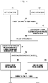
FIG. 6 is an operation flow diagram illustrating example operations of performing a call connection by the first electronic device and the second electronic device according to various embodiments. - A first electronic device (e.g., the first
electronic device 310 ofFIG. 3A andFIG. 3B or theelectronic device 400 ofFIG. 4 ) according to various embodiments may transmit a call connection request message (e.g., the SDP invite message defined in the SDP session protocol) to a second electronic device (e.g., the secondelectronic device 320 ofFIG. 3A andFIG. 3B or theelectronic device 500 ofFIG. 5 ) inoperation 610. - According to various embodiments, in order to determine, before a call connection is completed, whether the second
electronic device 320 supports the transmission filters 313 and 343 and the reception filters 325 and 355, the firstelectronic device 310 may transmit, to the secondelectronic device 320, the call connection request message including information of the transmission filters 313 and 343, an indicator indicating whether pre-processing of audio data or image data using a specific algorithm (e.g., a pre-processing algorithm using the NPU) is supportable, and capability information of theelectronic device 400, which is related to the transmission filters 313 and 343. For example, the call connection request message may be implemented in the form described, for example, in Table 1 below.[Table 1] [-->] INVITE m=audio 7010 RTP/AVP 110 100 98 b=AS:42 a=rtpmap: 110 EVS/16000 a=mediaproc: 110 upmodel=voice_up_coeff_1.1; downmodel=voice_down_coeff_1.1 a=audioattr:110 source [32000] send [16000] recv [16000] target [32000] a=npu:ver2.0 a=rtpmap:100 AMR-WB/16000/1 a=mediaproc: 100 upmodel=voice_up_coeff_1.1; downmodel=voice_down_coeff_1.1 a=audioattr:100 source [32000] send [16000] recv [16000] target [32000] a=npu:ver2.0 a=rtpmap:98 AMR/8000/1 m=video 7020 RTP/AVP 112 102 34 b=AS:1280 a=rtpmap: 112 H265/90000 a=mediaproc: 112 upmodel=video_up_coeff_1.02; downmodel=video_down_coeff_1.02 a=npu:ver2.0 a=imageattr:112 source [x=1440, y=2560] send [x=720, y=1280] recv [x=720, y=1280] target [x=1440, y=2560] a=rtpmap:102 H264/90000 a=mediaproc: 102 upmodel=video_up_coeff_1.02; downmodel=video_down_coeff_1.02 a=npu:ver2.0 a=imageattr:102 source [x=960, y=1280] send [x=480, y=640] recv [x=480, y=640] target [x=960, y=1280] a=rtpmap:34 H263/90000 a=imageattr:34 send [x=176,y=144] recv [x=176,y=144] - Referring to Table 1, the call connection request message may include: an indicator that indicates whether pre-processing of the audio data using the specific algorithm is supported (a=mediaproc); NPU information and whether processing using the neural processing unit (NPU) is supported (a=npu:ver2.0); identification information of the transmission filters 313 and 343 (upmodel=voice_up_coeff_1.1, upmodel=video_up_coeff_1.1); identification information of the reception filters 325 and 355 (downmodel=voice_down_coeff_1.1, downmodel=video_down_coeff_1.1); and quality information of the audio data or image data.
- According to various embodiments, in
operation 620, the secondelectronic device 320 may check capability of the secondelectronic device 320, which is related to a reception filter (e.g., thereception filter 325 ofFIG. 3A or thereception filter 355 ofFIG. 3B ). - According to various embodiments, the second
electronic device 320 may check transmission schemes of the audio data or the image data, which are supported by the firstelectronic device 310 and included in the call connection request message, and the secondelectronic device 320 may select at least one transmission scheme, which is supported by the secondelectronic device 320, from among the checked transmission schemes. - According to various embodiments, the second
electronic device 320 may check the capability of the secondelectronic device 320, which is related to the reception filters 325 and 355 for supporting the selected transmission scheme. - According to various embodiments, the capability of the second
electronic device 320, which is related to the reception filters 325 and 355 may include: whether post-processing that corresponds to pre-processing of the audio data or the image data using the specific algorithm included in the call connection request message is supportable; and whether the secondelectronic device 320 has an element (e.g., a central processing device (CPU), a graphic processing device (GPU), or a neural processing device (NPU)) capable of post-processing the audio data or the image data using the reception filters 325 and 355. - According to various embodiments, in
operation 630, the secondelectronic device 320 may transmit a response message (e.g., anSDP 200 OK message defined in the SDP protocol) to the firstelectronic device 310. - According to various embodiments, the response message may include the capability of the second
electronic device 320, which is related to the reception filters 325 and 355. For example, the response message may include; an indicator indicating whether post-processing that corresponds to pre-processing of the audio data or the image data using the included specific algorithm is supportable; and an indicator indicating whether the secondelectronic device 320 has an element (e.g., a central processing device (CPU), a graphic processing device (GPU), or a neural processing device (NPU)) capable of post-processing the audio data or the image data using the reception filters 325 and 355. For example, the response message may be implemented in the form described, for example, in Table 2 below.[Table 2] [<--] SIP/2.0 200 OK m=audio 12350 RTP/AVP 100 b=AS:41 a=rtpmap:100 AMR-WB/16000/1 a=mediaproc: 100 upmodel=voice_up_coeff_1.0; downmodel=voice_down_coeff_1.0 a=audioattr:100 source [32000] send [16000] recv [16000] target [32000] a=npu:ver1.0 m=video 15490 RTP/AVP 102 b=AS:640 a=rtpmap:102 H264/90000 a=mediaproc:102 upmodel=nobias1.01; downmodel=basedown1.01 a=npu:ver1.0 a=imageattr:102 source [x=960, y=1280] send [x=480, y=640] recv [x=480, y=640] target [x=960, y=1280] - Referring to Table 2, the response message may include: an indicator that indicates whether post-processing of the audio data or the image data using the specific algorithm is supported (a=mediaproc); NPU information and whether processing using the neural processing unit (NPU) is supported (a=npu:ver2.0); identification information of the transmission filters 313 and 343 (upmodel=voice_up_coeff_1.1, upmodel=video_up_coeff_1.1); identification information of the reception filters 325 and 355 (downmodel=voice_down_coeff_1.1, downmodel=video_down_coeff_1.1); and quality information of the audio data and the image data.
- According to various embodiments, in
operation 640, the firstelectronic device 310 may determine whether to pre-process the audio data or the image data using the transmission filters 313 and 343, based on the capability information of the secondelectronic device 320. - According to various embodiments, whether to pre-process the audio data or the image data may refer, for example, to pre-processing the audio data or the image data using the transmission filters 313 and 343.
- According to various embodiments, the first
electronic device 310 may check an indicator indicating whether post-processing of the audio data or the image data using the specific algorithm included in the response message is supported, and the firstelectronic device 310 may determine to pre-process the audio data or the image data using the specific algorithm. - According to various embodiments, in
operation 650, the firstelectronic device 310 may transmit a call connection confirmation message (e.g., an SDP ACK message defined in the SDP session protocol) to the secondelectronic device 320. - According to various embodiments, the call connection confirmation message may be a message indicating to perform the call connection using the transmission scheme of the audio data or the image data, which is included in the response message.
- According to various embodiments, in
operation 661, the firstelectronic device 310 may configure elements of the firstelectronic device 310, for the call connection. - According to various embodiments, the first
electronic device 310 may configure the elements for the call connection, based on information (e.g., a sampling scheme of the audio data, a sampling rate of the audio data, a compression scheme of the image data, or a resolution of the image data ) on at least one transmission scheme supported by the secondelectronic device 320, which is included in the response message. The firstelectronic device 310 may configure the elements for the call connection via various operations including activating themicrophone 311 to generate audio data, activating thecamera 341 to generate image data, or controlling thecommunication module 410 to transmit or receive data for call channel establishment. - According to various embodiments, in
operation 663, the secondelectronic device 320 may configure elements of the secondelectronic device 320, for the call connection. - According to various embodiments, the second
electronic device 320 may configure the elements for the call connection, based on information (e.g., a sampling scheme of the audio data, a sampling rate of the audio data, a compression scheme of the image data, or a resolution of the image data ) on at least one transmission scheme supported by the secondelectronic device 320, which is included in the response message. The secondelectronic device 320 may configure the elements for the call connection via various operations including activating themicrophone 311 to generate audio data, activating thecamera 341 to generate image data, or controlling thecommunication module 510 to transmit or receive data for call channel establishment. - According to various embodiments, in
operation 670, the firstelectronic device 310 and the secondelectronic device 320 may complete the call connection and may perform a call using a call channel. - According to various embodiments, the first
electronic device 310 and the secondelectronic device 320 may transmit and/or receive the audio data and/or the image data via the call channel. The firstelectronic device 310 and the secondelectronic device 320 may transmit the audio data or the image data, which is pre-processed using the transmission filters 313 and 343, or may post-process the received audio data or image data using the reception filters 325 and 355, so as to acquire audio data or image data having a quality similar to that of the original data or image data. -
FIG. 7 is a diagram illustrating an example screen in which a configuration for content transmission or reception is performed in an electronic device according to various embodiments. - According to various embodiments, a first electronic device (e.g., the first
electronic device 310 ofFIG. 6 ) and a second electronic device (e.g., the secondelectronic device 320 ofFIG. 6 ) may transmit, to a counterpart electronic device, audio data or image data using an audio data or image data processing scheme using a specific algorithm. Filters (e.g., the transmission filters 313 and 343 ofFIG. 3A andFIG. 3B , or the reception filters 325 and 355 ofFIG. 3A andFIG. 3B ) that pre-process or post-process audio data or image data may be generated via machine learning in order to exhibit high performance. The filters generated via machine learning may be used by a neural processing device of an electronic device. Processing of audio data or image data using the filters generated via machine learning may improve a sound quality or an image quality, but may increase power consumption. - An electronic device (e.g., the
electronic device 400 ofFIG. 4 or theelectronic device 500 ofFIG. 5 ) according to various embodiments may determine whether to pre-process or post-process audio data according to a user configuration. - Referring to
FIG. 7 , theelectronic device 400 may display, on a display 710 (e.g., thedisplay device 160 ofFIG. 1 ), a screen enabling to select whether to apply a soundquality enhancement function 711 during a call connection, or whether to apply an imagequality enhancement function 713 during the call connection. Theelectronic device 400 may determine whether to activate the sound quality enhancement function or the image quality enhancement function, based on a user input. - According to various embodiments, the
electronic device 400 may determine whether to activate the sound quality enhancement function or the image quality enhancement function according to a state of theelectronic device 400. For example, theelectronic device 400 may determine to deactivate the sound quality enhancement function or the image quality enhancement function in response to determining that the remaining battery capacity is equal to or less than a preconfigured value. As another example, theelectronic device 400 may determine to activate the sound quality enhancement function or the image quality enhancement function in response to determining that a quality of cellular communication used for the call connection has a value equal to or less than a preconfigured value. - An electronic device according to various example embodiments may include; a communication module comprising communication circuitry configured to transmit and/or receive data using a call channel established via a call connection to an external electronic device; and a processor, wherein the processor is configured to control the electronic device to: transmit a call connection request message to establish a call channel between an external electronic device and the electronic device; receive a response message from the external electronic device; based on capability information of the external electronic device related to the call connection and included in the response message, determine whether to pre-process a content transmitted via the call connection using a transmission filter configured to change a quality of the content; transmit, to the external electronic device, a call connection confirmation message indicating whether to pre-process the content; and control the communication module to complete establishing the call channel, wherein the connection request message includes capability information of the electronic device related to the filter.
- In the electronic device according to various example embodiments, the capability information of the electronic device may include an indicator configured to indicate whether an element of the electronic device configured to process the transmission filter is present.
- In the electronic device according to various example embodiments, elements of the electronic device may include a neural processing unit (NPU).
- In the electronic device according to various example embodiments, the call connection request message may be configured to include identification information of the NPU.
- In the electronic device according to various example embodiments, the call connection request message may be configured to include identification information of the transmission filter.
- In the electronic device according to various example embodiments, the capability information of the electronic device may include a resolution or a sampling rate of a content that may be processed using the transmission filter.
- In the electronic device according to various example embodiments, the call connection request message may include an indicator configured to indicate whether processing of the content based on the transmission filter is supported.
- In the electronic device according to various example embodiments, the processor may be configured to determine, based on the response message, whether the reception filter corresponding to the transmission filter is present in the external electronic device, and determine whether to use the transmission filter, based on a result of the determination.
- In the electronic device according to various example embodiments, the processor may be configured to control the electronic device to activate the transmission filter and an element to control the transmission filter before completion of the call connection in response to determining to use the transmission filter.
- An electronic device according to various example embodiments may include: a communication module comprising communication circuitry configured to transmit and/or receive data using a call channel established via a call connection to an external electronic device; and a processor, wherein the processor is configured to control the electronic device to: receive a call connection request message to establish a call channel between an external electronic device and the electronic device; transmit, to the external electronic device, a response message including capability information of the electronic device related to a reception filter for pre-processing of a content received via the call connection; receive, from the external electronic device, a call connection confirmation message including an indicator indicating whether to pre-process the content using a transmission filter corresponding to the reception filter; and activate the reception filter based on the indicator.
- In the electronic device according to various example embodiments, the capability information of the electronic device may include an indicator configured to indicate whether an element of the electronic device configured to process the reception filter, is present.
- In the electronic device according to various example embodiments, elements of the electronic device may include a neural processing unit (NPU).
- In the electronic device according to various example embodiments, the response message may be configured to include identification information of the reception filter.
- In the electronic device according to various example embodiments, the response message may include an indicator configured to indicate whether processing of the content based on the reception filter is supported.
-
FIG. 8 is a flowchart illustrating an example operation method of an electronic device according to various embodiments. - According to various embodiments, in
operation 810, an electronic device (e.g., theelectronic device 400 ofFIG. 4 ) may transmit a call connection request message to establish a call channel to an external electronic device (e.g., theelectronic device 500 ofFIG. 5 ). - According to various embodiments, in order to determine, before a call connection is completed, whether the external
electronic device 500 supports post-processing of audio data or image data using a specific algorithm, theelectronic device 400 may transmit, to the externalelectronic device 500, the call connection request message including an indicator indicating whether pre-processing of audio data or image data using a specific algorithm (e.g., a pre-processing algorithm using the NPU) is supportable, and capability information of theelectronic device 400, which is related to the transmission filters 313 and 343. - According to various embodiments, in
operation 820, theelectronic device 400 may receive, from the externalelectronic device 500, a response message including capability information of the externalelectronic device 500 related to the call connection. - According to various embodiments, the response message may include capability of the external
electronic device 500 related to the reception filters 325 and 355. For example, the response message may include; an indicator indicating whether post-processing that corresponds to pre-processing of the audio data or the image data using the included specific algorithm is supportable; and an indicator indicating whether the externalelectronic device 500 has an element (e.g., a central processing device (CPU), a graphic processing device (GPU), or a neural processing device (NPU)) capable of post-processing the audio data or the image data using the reception filters 325 and 355. - According to various embodiments, in
operation 830, theelectronic device 400 may determine whether to pre-process a content (e.g., audio data or image data) based on the capability information of the externalelectronic device 500. - According to various embodiments, pre-processing of the content may refer, for example, to pre-processing the audio data or the image data using the transmission filters 313 and 343 before the content is input to an encoder (e.g., the
encoder 315 ofFIG. 3A or theencoder 345 ofFIG. 3B ). - According to various embodiments, the
electronic device 400 may check an indicator indicating whether post-processing of the audio data or the image data using the specific algorithm included in the response message is supported, and theelectronic device 400 may determine to pre-process the audio data or the image data using the specific algorithm. - According to various embodiments, the
electronic device 400 may check the capability information of the externalelectronic device 500, and may determine that the externalelectronic device 500 is to support pre-processing of the audio data or the image data using the specific algorithm. - According to various embodiments, in
operation 840, theelectronic device 400 may transmit, to the externalelectronic device 500, a call connection confirmation message that indicates whether to use the transmission filters. - According to various embodiments, the call connection confirmation message may be a message indicating to perform the call connection using the transmission scheme of the audio data or the image data included in the response message.
-
FIG. 9 is a flowchart illustrating an example operation method of an electronic device according to various embodiments. - According to various embodiments, in
operation 910, an electronic device (e.g., theelectronic device 500 ofFIG. 5 ) may receive a call connection request message to establish a call channel from an external electronic device (e.g., theelectronic device 400 ofFIG. 4 ). - According to various embodiments, the call connection request message may include quality information of audio data or image data which can be transmitted by the external
electronic device 500, model information of the transmission filters 313 and 343 of the externalelectronic device 500, version information, identification information of the transmission filters 313 and 343, which includes capability information of the transmission filters 313 and 343, and capability information of the externalelectronic device 500, which is related to the transmission filters 313 and 343. - According to various embodiments, in
operation 920, theelectronic device 500 may transmit, to the externalelectronic device 400, a response message including capability information related to a reception filter for adjustment of a quality of a content (e.g., audio data or image data). - According to various embodiments, in
operation 930, theelectronic device 500 may receive a call connection confirmation message that indicates whether to use the transmission filters 313 and 343 of the externalelectronic device 400. - According to various embodiments, in
operation 940, theelectronic device 500 may configure elements of theelectronic device 500, for the call connection. - According to various embodiments, the
electronic device 500 may configure the elements for the call connection, based on information (e.g., a sampling scheme of the audio data, a sampling rate of the audio data, a compression scheme of the image data, or a resolution of the image data ) on at least one transmission scheme supported by theelectronic device 500, which is included in the response message. Theelectronic device 500 may configure the elements for the call connection via various operations including activating themicrophone 311 to generate audio data, activating thecamera 341 to generate image data, or controlling thecommunication module 510 to transmit or receive data for call channel establishment. - The embodiments described above are embodiments of acquiring, before a call connection between the first
electronic device 310 and the secondelectronic device 320, information on whether thetransmission filter 313 and thereception filter 325 are supported. According to various embodiments, a variety of information including whether to support thetransmission filter 313 and thereception filter 325 may be acquired before the call connection. According to an embodiment, when performing a video call connection, the firstelectronic device 310 and the secondelectronic device 320 may acquire information including whether various schemes for a video call are supported, before the call connection. For example, the firstelectronic device 310 and the secondelectronic device 320 may acquire, before the call connection, information on whether to support a scheme (hereinafter, referred, for example to as a metadata-based video call) of performing a video call by exchanging data (or information) for rendering an image without transmitting the image, from among various schemes of performing the video call. - According to various embodiments, the metadata-based video call scheme may refer to a video call scheme of exchanging metadata, e.g., data for generating an emoji including an image. The metadata-based video call scheme may be a scheme of exchanging metadata having a size smaller than that of image data, which is output during a video call, without exchanging the image data. The electronic device having received the metadata may generate at least one frame including an emoji, which reflects characteristics (e.g., features) of the metadata, by a scheme of applying the metadata to an emoji model (e.g., 3D modeling data) stored in the electronic device. The electronic device may generate (e.g., render) image data including at least one frame, and may output the image data on a display (e.g., the
display device 160 ofFIG. 1 ). The emoji may, for example, be an image corresponding to a user of an electronic device (e.g., the firstelectronic device 310 and/or the second electronic device 320), and may be an image generated by a scheme of inputting metadata to modeling data stored in theelectronic devices - Hereinafter, a description of acquiring information related to a metadata-based video call before a call-connection between the first
electronic device 310 and the secondelectronic device 320 will be described in greater detail. -
FIG. 10A is a block diagram of an electronic device according to various embodiments. - According to various embodiments, an electronic device 1000 (e.g., the
electronic device 101 ofFIG. 1 , the firstelectronic device 310 ofFIG. 3A andFIG. 3B , or theelectronic device 400 ofFIG. 4 ) illustrated inFIG. 10A may include a communication module (e.g., including communication circuitry) 1010 (e.g., thewireless communication module 192 ofFIG. 1 ) and a processor (e.g., including processing circuitry) 1020 (e.g., theprocessor 120 ofFIG. 1 ). - According to various embodiments, the
communication module 1010 may include various communication circuitry and transmit audio data and/or image data using a communication channel (e.g., a cellular communication channel) established via a call connection to an external electronic device (e.g., the secondelectronic device 320 ofFIG. 3A and3B ). - According to various embodiments, the
processor 1020 may include various processing circuitry and perform negotiation with the external electronic device using a scheme defined in a session description protocol in order to determine characteristics of data transmitted or received when a call is connected between the external electronic device and theelectronic device 1000. - Hereinafter, it is assumed, for ease and convenience of description, that the
electronic device 1000 corresponds to a transmission terminal (e.g., the firstelectronic device 310 ofFIG. 3A ), and an external electronic device corresponds to a second electronic device (e.g., the secondelectronic device 320 ofFIG. 3A ), and a specific embodiment, in which information on whether a metadata-based video call is supported is acquired before a call-connection, will be described. - According to various embodiments, the
processor 1020 may activate a camera (e.g., thecamera module 180 ofFIG. 1 ) in response to detecting execution (or a user input to request a video call from the externalelectronic device 320 during execution of the video call application) of a video call application that performs a video call with the secondelectronic device 320, and may display a preview image collected using thecamera 180 on a display (e.g., thedisplay device 160 ofFIG. 1 ). - According to various embodiments, the
processor 1020 may control thecommunication module 1010, so that a call connection request message for establishment of a call channel between the externalelectronic device 320 and theelectronic device 1000 is transmitted from the externalelectronic device 320. For example, the call connection request message may be implemented in the form of an SDP invite message defined in SDP. - According to various embodiments, the call connection request message may include quality information of audio data or image data which could be transmitted by the
electronic device 1000. For example, the quality information of audio data may include a sampling rate of audio data that may be generated using a microphone (e.g., themicrophone 311 ofFIG. 3A ), a sampling rate of audio data that can be transmitted over a network (e.g., thenetwork 320 ofFIG. 3A ), or a sampling rate of audio data that can be received by the external electronic device. The quality information of image data may include a resolution of image data that may be generated using a camera (e.g., thecamera 341 ofFIG. 3B ), a resolution of image data that can be transmitted over thenetwork 320, or a resolution of image data that can be received by the external electronic device. - According to various embodiments, in order to determine, before a call connection is completed, whether the external
electronic device 320 supports a metadata-based video call, theprocessor 1020 may transmit, to the externalelectronic device 320, the call connection request message including capability information of theelectronic device 1000, which is related to whether the metadata-based video call is supported. - According to various embodiments, the capability information of the
electronic device 1000 may include information indicating whether an element of theelectronic device 1000, which is required in a metadata-based video call scheme, is present. According to an embodiment, the element of theelectronic device 1000 may include at least one 3D model capable of rendering an emoji, and the capability information of theelectronic device 1000 may include information indicating whether an emoji model (or a group of emoji models) is present in theelectronic device 1000. - According to various embodiments, the call connection request message may include identification information of a model reflecting metadata required in the metadata-based video call scheme. The identification information of the model may include version information of the model (e.g., information indicating a type (e.g., person, animal, or alien) of an emoji that can be generated using metadata by the model), manufacturer information of the model, and standards (e.g., MPEG-4 face and body animation) used by the model.
- According to various embodiments, the
processor 1020 may receive, from the externalelectronic device 320, a response message in response to the call connection request message. For example, the response message may be implemented in the form of anSDP 200 OK message defined in the SDP protocol. - According to various embodiments, the response message transmitted by the external
electronic device 320 may include capability information of the externalelectronic device 320, which is related to the call connection. - According to various embodiments, based on the capability information of the
electronic device 1000, which is included in the call connection request message, the externalelectronic device 320 may select a data transmission scheme (e.g., a data transmission scheme supportable by the externalelectronic device 320, in a sampling scheme and a sampling rate of the audio data or a compression format and a resolution of the image data) which is supportable by theelectronic device 1000. Capability information of the externalelectronic device 320 may include information on the data transmission scheme selected by the externalelectronic device 320. - According to various embodiments, the capability information of the external
electronic device 320 may include information on elements (e.g., software- implemented elements (e.g., a model to reflect metadata) or hardware-implemented elements (e.g., a graphic processing unit (GPU), or any combination thereof) that support the metadata-based video call scheme performed between the externalelectronic device 320 and theelectronic device 1000. - According to various embodiments, the
processor 1020 may determine whether to perform the metadata-based video call, based on the capability information of the externalelectronic device 320, which is included in the response message. - According to various embodiments, the
processor 1020 may check the capability information of the externalelectronic device 320, which is included in the response message, may determine whether the externalelectronic device 320 can support the metadata-based video call, or may check, if the metadata-based video call is supported, information of the model used for the metadata-based video call or standard information to be used for generating metadata that is to be used for the metadata-based video call. - According to various embodiments, the
processor 1020 may transmit, to the externalelectronic device 320, a call connection confirmation message including an indicator that indicates whether the metadata-based video call is supported or an indicator that indicates whether to perform rendering using the metadata. - According to various embodiments, the call connection confirmation message may be a message indicating to perform the call connection using the transmission scheme of the audio data or the image data, which is included in the response message. The call connection confirmation message may be, for example, an SDP ACK message defined in the SDP session protocol.
- According to various embodiments, the
electronic device 1000 may perform various operations for a call connection to the externalelectronic device 320 having received the call connection confirmation message, wherein the operations include, for example: activating themicrophone 311 to generate audio data; activating thecamera 341 to generate image data; activating an image render (a graphic library and/or a graphic processing device (GPU)) to render image data that is to be output on a screen; activating the model for the metadata-based video call; or controlling thecommunication module 1010 to transmit or receive data for call channel establishment. Various operations for the call connection to the externalelectronic device 320, which are performed by theelectronic device 1000 may be implemented using a function provided by a running video call application. Activating the model for the metadata-based video call by theelectronic device 1000 may include, for example, loading a 3D model (modeling data), etc. stored in anonvolatile memory 134, in avolatile memory 132 by the electronic device (e.g., thevideo call application 146 and an image renderer). According to various embodiments, by including the capability information of theelectronic device 400, which is related to the metadata-based video call, in the call connection request message, theprocessor 1020 may activate, before the call connection to the externalelectronic device 320 is completed, an element (e.g., an image renderer and/or a 3D graphic model) necessary for performing the metadata-based video call. Therefore, after the call connection is completed, by activating the element necessary for performing the metadata-based video call, degradation of a call channel quality, which may occur, may be prevented, and by transmitting metadata having a size smaller than that of image data, data consumption used for the video call may be reduced. -
FIG. 10B is a block diagram illustrating an example electronic device according to various embodiments. - Referring to
FIG. 10B , theelectronic device 1000 according to various embodiments may include a call connection management unit (e.g., including processing circuitry and/or executable program elements) 1030 configured to perform or manage a call connection, an audio data processor (e.g., including processing circuitry and/or executable program elements) 1040 configured to transmit audio data or process the received audio data, an image data processor (e.g., including processing circuitry and/or executable program elements) 1050 configured to transmit image data or process the received image data, a memory 1061 (e.g., thememory 130 ofFIG. 1 ), a camera 1062 (e.g., thecamera module 180 ofFIG. 1 ), a microphone 1063 (e.g., the input device (150) ofFIG. 1 ), a display 1064 (e.g., thedisplay device 160 ofFIG. 1 ), and a speaker 1065 (e.g., thesound output device 155 ofFIG, 1 ). - According to various embodiments, the
call connection manager 1030 may include: anSDP parser 1031 configured to parse a message received from an external electronic device (e.g., the secondelectronic device 320 ofFIG. 3A andFIG. 3B ) while a call connection is being performed; anSDP writer 1032 configured to generate a message transmitted to the externalelectronic device 320, for performing of the call connection; acall session manager 1033 configured to manage a connection or termination for a call session; and a metadata-based videocall determination unit 1034 configured to determine whether to perform a metadata-based video call, based on capability information of the externalelectronic device 320, which is included in a response message received from the externalelectronic device 320. - According to various embodiments, the
audio data processor 1040 may include: anaudio acquisition unit 1041 configured to acquire audio data using themicrophone 1063; an audio transmission filter 1042 (e.g., thetransmission filter 313 ofFIG. 3A ) that is configured to perform filtering for audio data; an audio encoder 1043 (e.g., theencoder 315 ofFIG. 3A ) configured to encode audio data, which is transmitted by thetransmission filter 1042, to compress the audio data; and a packetizer 1044 (e.g., thepacketizer 317 ofFIG. 3A ) configured to convert encoded audio data into audio packet data in a packet form. - According to various embodiments, the
audio data processor 1040 in terms of receiving audio data may include: a depacketizer 1045 (e.g., thedepacketizer 321 ofFIG. 3A ) configured to convert audio packet data received from the externalelectronic device 320 into encoded audio data; an audio decoder 1046 (e.g., thedecoder 323 ofFIG. 3A ) configured to decode encoded audio data; an audio reception filter 1047 (e.g., thereception filter 325 ofFIG. 3A ) configured to change a sampling rate of decoded audio data; and anaudio output unit 1048 configured to output audio via thespeaker 465. - According to various embodiments, the
image data processor 1050 in terms of transmitting image data may include: animage acquisition unit 1051 configured to acquire an image captured by thecamera 1062; an image transmission filter 1052 (e.g., thetransmission filter 343 ofFIG. 3B ) that is configured to perform filtering for image data; an image encoder 1053 (e.g., theencoder 345 ofFIG. 3B ) configured to encode image data to compress the image data; and a packetizer 1054 (e.g., thepacketizer 347 ofFIG. 3B ) configured to convert encoded image data into image packet data in a packet form. - According to various embodiments, the
image data processor 1050 in terms of receiving image data may include: a depacketizer 1055 (e.g., thedepacketizer 351 ofFIG. 3B ) configured to convert image packet data received from the externalelectronic device 320 into encoded image data; an image decoder 1056 (e.g., thedecoder 353 ofFIG. 3B ) configured to decode encoded image data which has been converted by thedepacketizer 1055; an image reception filter 1057 (e.g., thereception filter 355 ofFIG. 3B ) configured to change a resolution of decoded image data; and animage output unit 1058 configured to output, via thedisplay 464, image data generated by thereception filter 1057. - According to various embodiments, the
SDP writer 1032 may generate a call connection request message based on a control of thecall session manager 1033, and may transmit the call connection request message to the externalelectronic device 320 via thecommunication module 1010. For example, the call connection request message may be implemented in the form of an SDP invite message defined in SDP. - According to various embodiments, a call connection message may include capability information of the
electronic device 400, which is related to the metadata-based video call. - According to various embodiments, the
SDP parser 1031 may parse a response message received via thecommunication module 410. The response message may include the capability information of the externalelectronic device 320, which is related to the metadata-based video call. For example, the response message may include an indicator indicating whether the externalelectronic device 320 can support the metadata-based video call, and an element (e.g., an indicator indicating whether ametadata depacketizer 1071 configured to decode metadata or animage renderer 1072 configured to render metadata is provided) allowing the externalelectronic device 320 to perform the metadata-based video call. - According to various embodiments, the capability information of the external
electronic device 320, which is extracted via parsing the response message by theSDP parser 1031, may be transmitted to the metadata-based videocall determination unit 1034 via thecall session manager 1033. - According to various embodiments, the metadata-based video
call determination unit 1034 may determine whether to perform the metadata-based video call, based on the capability information of the externalelectronic device 320. - According to various embodiments, the metadata-based video
call determination unit 1034 may check an indicator indicating whether the metadata-based video call is supported, which is included in the response message, and may determine whether the externalelectronic device 320 supports the metadata-based video call. - According to various embodiments, the metadata-based video
call determination unit 1034 may determine that the externalelectronic device 320 supports the metadata-based video call, based on the capability information of the externalelectronic device 320, and may determine to perform the metadata-based video call, in response to determination that the externalelectronic device 320 supports the metadata-based video call. - According to various embodiments, the metadata-based video
call determination unit 1034 may activate: ametadata generator 1073 configured to detect feature points from images acquired by elements (e.g., the image acquisition unit 1051) necessary for performing the metadata-based video call, in response to determination to perform the metadata-based video call, and generate metadata based on the feature points; ametadata packetizer 1074 configured to convert the metadata received from themetadata generator 1073 into packet data in a packet form; themetadata depacketizer 1071 configured to convert the metadata in the packet form, which is received from the externalelectronic device 320; or theimage renderer 1072 configured to generate an image in a scheme of rendering the metadata. - According to various embodiments, the
call session manager 1033 may transmit a call connection confirmation message indicating whether to activate the metadata-based video call, to the externalelectronic device 320 via thecommunication module 1010. - According to various embodiments, elements implemented on the
processor 1020 of theelectronic device 1000 may be software-implemented elements, but some elements may be implemented in hardware according to a design scheme. For example, theimage renderer 1072 may be a graphic library which is software-implemented so as to be stored in a memory (e.g., thememory 130 ofFIG. 1 ), and theimage renderer 1072 may be a graphic processing unit (GPU) which may be hardware-implemented. -
FIG. 11A is a diagram illustrating an example of extracting metadata from an acquired image, in an electronic device according to various embodiments. - According to various embodiments, an electronic device (e.g., the
electronic device 1000 ofFIG. 10A ) may analyze an image collected by a camera (e.g., thecamera 1062 ofFIG. 10B ), and may extract feature points of one or more objects included in the image. For example, objects of a user' s face may include eyebrows, eyes, a nose, a mouth, a tongue, or a face shape, and objects constituting a part of the user' s body may include hands, arms, a torso, or legs. The feature points of the image may refer to points capable of expressing characteristics of the object (e.g., a shape of the object, a size of the object, and a position of the object). For example, the feature points may refer to points recognized, by theelectronic device 1000, as the object (e.g., eyes or a nose) constituting the user' s face. According to an embodiment, themetadata generator 1073 that is software- or hardware-implemented on a processor (e.g., theprocessor 1020 ofFIG. 10A ) of theelectronic device 1000 may extract feature points of the object from the image acquired by theimage acquisition unit 1051. - According to various embodiments, the
electronic device 1000 may group at least a part of the extracted feature points, may acquire information of variables including characteristics of the object based on information of the feature points, and may generate metadata including information of the variables. The variables may be variables for determining characteristics (e.g., expression of the object) of elements (e.g., elements for implementing the characteristics of the object included in an image to be rendered, which may be eyes, a nose, a mouth, or body if the object in the image is an animal) included in an image to be rendered, and information of the variables may refer to specific values of variables used to determine the characteristics (e.g., positions of the objects, sizes of the objects, directions of the objects, or rotation angles of the objects) of the objects or relationships between the objects (e.g., a distance between an object (eye) and another object (nose)). Themetadata generator 1073 may generate metadata including the characteristics of the objects and the relationships between the objects, which are generated based on information of the feature points (e.g., a distance between the feature points or positions of the feature points). - According to various embodiments, variables and/or metadata including features of the objects may include values corresponding to face animation parameters (FAPs) and/or feature points defined in MPEG-4 face and body animation (MPEG-4 FBA). For example, the variables and/or metadata including the features of the objects may include data corresponding to at least a part of iris diameter (IRISD), eye separation (ES), eye-nose separation (ENS), mouth-nose separation (MN), mouth width (MW), and angle unit (AU). According to various embodiments, metadata may be configured according to syntax of FAP data.
- The metadata may refer to data obtained by grouping information of the variables. The
metadata generator 1073 that is software- or hardware-implemented on theprocessor 1020 of theelectronic device 1000 may acquire information of the variables based on information of the extracted feature points, and may generate metadata based on the acquired information of the variables. - Referring to
FIG. 11A , themetadata generator 1073 may extract anobject 1100 from an image acquired using thecamera 1062, and may extract feature points of theobject 1100. Various feature point extraction algorithms may be used for a scheme of extracting the feature points. For example, themetadata generator 1073 may compare data including information (e.g., information on a shape of the feature points) related to feature points stored in thememory 130 with at least a part of theobject 1100 in the image acquired using thecamera 1062, and may calculate a similarity between shapes of the feature points included in the data and at least the part of theobject 1100. Themetadata generator 1073 may extract the feature points from at least the part of theobject 1100 in response to the calculated similarity being equal to or greater than a preconfigured value. - The
metadata generator 1073 may acquire information of the variables based on information of the extracted feature points. For example, themetadata generator 1073 may acquire, based on information of the feature points, information of various variables including apupil size 1101 of the object, adistance 1103 between two eyes of the object, adistance 1105 between eyes and nose of the object, adistance 1107 between nose and mouth of the object, and awidth 1109 of mouth of the object. Themetadata generator 1073 may generate metadata that includes a set of the acquired information of the variables. -
FIG. 11B is a diagram illustrating an example of rendering an image based on a model and metadata, in an electronic device according to various embodiments. - According to various embodiments, an electronic device (e.g., the
electronic device 1000 ofFIG. 10A ) may select, based on capability information of an external electronic device (e.g., the externalelectronic device 320 ofFIG. 3A ), which is included in a response message received from the externalelectronic device 320, a model to perform rendering from among models implemented in theelectronic device 1000, and may generate anemoji 1110, which is to be included in an image to be rendered, using the selected model. - According to various embodiments, the
electronic device 1000 may store at least one model in a memory (e.g., thememory 1061 ofFIG. 10A ). At least one model may be differently implemented depending on a type of an object to be rendered. For example, various models including a model for rendering a dinosaur, a model for rendering a pet, and a model for rendering an entertainer may be stored in thememory 1061. Theelectronic device 1000 may generate theemoji 1110 included in the image to be rendered by loading the selected model on thememory 1061 and inputting, to the model, metadata received from the externalelectronic device 320. According to an embodiment, theimage renderer 1072 implemented on theprocessor 1020 may receive metadata from themetadata depacketizer 1071, and may input the metadata to the model loaded on thememory 130, so as to generate theemoji 1110 included in the image to be rendered. Theimage renderer 1072 may render the image including theemoji 1110 using a resource provided by theprocessor 1020 or a resource provided by a separate graphic processing unit. The rendered image may be displayed on a display (e.g., thedisplay 1064 ofFIG. 10B ). - Referring to
FIG. 11B , theelectronic device 1000 may select a model that renders a pet based on a response message from the externalelectronic device 320, and may input, to the selected model, metadata received from the externalelectronic device 320. For example, theelectronic device 1000 may generate the emoji included in the image to be rendered, according to a scheme of inputting, to the selected model, information on apupil size 1101 of the object, adistance 1103 between two eyes of the object, adistance 1105 between eyes and nose of the object, adistance 1107 between nose and mouth of the object, and awidth 1109 of mouth of the object, which is included in the metadata. Theelectronic device 1000 may render the image including the generatedemoji 1110, and may display the rendered image on thedisplay 1064. -
FIG. 12 is an operation flow diagram illustrating example operations of performing a call connection by the first electronic device and the second electronic device according to various embodiments. - A first electronic device (e.g., the first
electronic device 310 ofFIG. 3A andFIG. 3B or theelectronic device 1000 ofFIG. 10A ) according to various embodiments may transmit a call connection request message (e.g., the SDP invite message defined in the SDP session protocol) to a second electronic device (e.g., the secondelectronic device 320 ofFIG. 3A andFIG. 3B ) inoperation 1210. - According to various embodiments, in order to determine, before a call connection is completed, whether the external
electronic device 320 supports a metadata-based video call, the firstelectronic device 1000 may transmit, to the externalelectronic device 320, the call connection request message including capability information of theelectronic device 1000, which is related to whether the metadata-based video call is supported. For example, the call connection request message may be implemented in the form described, for example, in Table 3 below.[Table 3] [-->] INVITE m=audio 7010 RTP/AVP 110 100 98 b=AS:42 a=rtpmap: 110 EVS/16000 a=rtpmap:100 AMR-WB/16000/1 a=rtpmap:98 AMR/8000/1 m=video 7020 RTP/AVP 112 102 34 b=AS:1280 a=rtpmap: 112 H265/90000 a=imageattr:112 send [x=720, y=1280] recv [x=720, y=1280] a=emoji_metadata:112 modelinfo=samsung_emoji_model_set_v2 facial_feature=MPEG4_facial_animation_standard a=rtpmap:102 H264/90000 a=imageattr:102 send [x=480, y=640] recv [x=480, y=640] a=emoji_metadata:102 modelinfo=samsung_emoji_model_set_v2 facial_feature=MPEG4_facial_animation_standard a=rtpmap:34 H263/90000 a=imageattr:34 send [x=176, y=144] recv [x=176, y=144] - Referring to Table 3, the call connection request message may include: information indicating that the first
electronic device 310 supports the metadata-based video call (a = emoji_metadata); information of a model that can be used in performing a metadata-based emoji video call (modelinfo=Samsung_emoji_model_set_v2); or standard information of metadata (facial_feature = MPEG4_facial_animation_standard). - According to various embodiments, in
operation 1220, the secondelectronic device 320 may check capability information of the secondelectronic device 320 related to the metadata-based video call. - According to various embodiments, the second
electronic device 320 may check the capability information of the firstelectronic device 310, which is related to the metadata-based video call of the firstelectronic device 310, which is included in the call connection request message, and the secondelectronic device 320 may select at least one video call scheme supported by the secondelectronic device 320 from among checked video call schemes. - According to various embodiments, in
operation 1230, the secondelectronic device 320 may transmit a response message (e.g., anSDP 200 OK message defined in the SDP protocol) to the firstelectronic device 310. - According to various embodiments, the response message may include capability of the second
electronic device 320, which is related to the metadata-based video call. For example, the response message may include at least one of an indicator indicating whether the metadata-based video call is supported, an indicator indicating model information used for the metadata-based video call, or an indicator indicating standard information used to generate metadata. For example, the response message may be implemented in the form described, for example, in Table 4 below.[Table 4] [<--] SIP/2.0 200 OK m=audio 12350 RTP/AVP 100 b=AS:41 a=rtpmap:100 AMR-WB/16000/1 m=video 15490 RTP/AVP 102 b=AS:640 a=rtpmap:102 H264/90000 a=imageattr:102 send [x=480, y=640] recv [x=480, y=640] a=emoji_metadata: 102 modelinfo=samsung_emoji_model_set_v2 facial_feature=MPEG4_facial_animation_standard - Referring to Table 4, the response message may include: an indicator indicating whether the second
electronic device 320 supports the metadata-based video call (a=emoji_metadata); information on a model used when the metadata-based video call is performed (modelinfo+Samsung_emoji_model_set_v2); and standard information used when metadata is generated (facial_feature=MPEG4_facial_animation_standard). - According to various embodiments, in
operation 1240, the firstelectronic device 1000 may determine whether to perform the metadata-based video call, based on the capability information of the secondelectronic device 320. - According to various embodiments, the first
electronic device 1000 may confirm an indicator indicating that the metadata-based video call is supported, which is included in the response message, and may determine to perform the metadata-based video call. - According to various embodiments, the first
electronic device 1000 may confirm an indicator indicating that the metadata-based video call is not supported, which is included in the response message, and may determine not to perform the metadata-based video call. The firstelectronic device 1000 may determine not to perform the metadata-based video call, in response to confirming that no indicator indicating that the metadata-based video call is supported is present in the response message. If the metadata-based video call is not performed, the firstelectronic device 1000 may determine to perform a video call in a manner of exchanging images (or image streams) transmitted by theelectronic device 1000 or the externalelectronic device 320. - According to various embodiments, in
operation 1250, the firstelectronic device 1000 may transmit a call connection confirmation message (e.g., an SDP ACK message defined in the SDP session protocol) to the secondelectronic device 320. - According to various embodiments, the call connection confirmation message may include an indicator indicating whether to perform the metadata-based video call.
- According to various embodiments, in
operation 1261, the firstelectronic device 1000 may configure elements of the firstelectronic device 1000, for the call connection. - According to various embodiments, the
electronic device 1000 may perform various operations for a call connection to the externalelectronic device 320 having received the call connection confirmation message, wherein the operations include: activating themicrophone 311 to generate audio data; activating thecamera 341 to generate image data; activating a model configured to perform rendering, which is included in a metadata-based video call scheme; or controlling thecommunication module 1010 to transmit or receive data for call channel establishment. - According to various embodiments, in
operation 1263, the secondelectronic device 320 may configure elements of the secondelectronic device 320, for the call connection. - According to various embodiments, in response to determining to perform the metadata-based video call, the second
electronic device 320 may activate elements (e.g., themetadata depacketizer 1071 ofFIG. 10B , theimage renderer 1072 ofFIG. 10B , themetadata generator 1073 ofFIG. 10B , or themetadata packetizer 1074 ofFIG. 10B ) necessary for performing the metadata-based video call. Activating of the model for the metadata-based video call by the secondelectronic device 320 may include, for example, loading the model (modeling data) stored in thenonvolatile memory 134, in thevolatile memory 132 by the electronic device (e.g., thevideo call application 146 and the image renderer). - According to various embodiments, in
operation 1270, the firstelectronic device 1000 and the secondelectronic device 320 may complete the call connection and may perform a call using a call channel. - According to various embodiments, the first
electronic device 1000 and the secondelectronic device 320 may transmit and/or receive metadata via the call channel. The firstelectronic device 1000 or the secondelectronic device 320 may generate theemoji 1110 included in the image to be rendered, by inputting the received metadata into the model loaded in thememory 130. The firstelectronic device 1000 and the secondelectronic device 320 may display, on thedisplay 1061, an image generated by rendering the image including theemoji 1110. The firstelectronic device 1000 and the secondelectronic device 320 may implement a video call, in which data consumption is relatively low, via a video call in a manner of exchanging metadata having a capacity smaller than that of an image stream. - According to various example embodiments, an electronic device may include: a communication module comprising communication circuitry configured to transmit and/or receive data using a call channel established via a call connection to an external electronic device; and a processor, wherein the processor is configured to control the electronic device to: transmit a call connection request message to establish a call channel between an external electronic device and the electronic device; receive a response message from the external electronic device; determine whether to perform, via the call connection, a metadata-based video call using an image including an emoji generated based on metadata, based on the capability information of the external electronic device related to the call connection and included in the response message; transmit, to the external electronic device, a call connection confirmation message indicating whether to perform the metadata-based video call; and control the communication module to complete establishing the call channel, wherein the call connection request message includes capability information of the electronic device related to whether to support the metadata-based video call.
- In the electronic device according to various example embodiments, the capability information of the electronic device may include an indicator configured to indicate whether an element of the electronic device, which is configured to perform the metadata-based video call, is present.
- In the electronic device according to various example embodiments, the element of the electronic device may include a model that generates an emoji based on the metadata.
- In the electronic device according to various example embodiments, the call connection request message may include identification information of at least one model which is supportable by the electronic device.
- In the electronic device according to various example embodiments, the response message may include identification information of at least one model which is supportable by the external electronic device.
- In the electronic device according to various example embodiments, the processor may be configured to control the electronic device to: after establishment of the call channel is completed, receive data for generating an image from an external electronic device that supports the metadata-based video call; generate an emoji corresponding to the metadata by inputting the data to the model; and output the image including the generated emoji on a display.
- In the electronic device according to various example embodiments, the processor may be configured to control the electronic device to: receive an input (e.g., a user input) requesting a change of the model based on being connected to the external electronic device via the call channel, and transmit, to the external electronic device, an indicator indicating the change of the model.
- In the electronic device according to various example embodiments, the processor may be configured to control the electronic device to: receive, after establishing the call channel is completed, image data from an external electronic device that does not support rendering based on the metadata, and output the image data on the display.
-
FIG. 13 is a flowchart illustrating anexample operation method 1300 of an electronic device according to various embodiments. - According to various embodiments, in
operation 1310, an electronic device (e.g., theelectronic device 1000 ofFIG. 10A ) may transmit a call connection request message to establish a call channel. - According to various embodiments, in order to determine, before a call connection is completed, whether the external
electronic device 320 supports a metadata-based video call, theprocessor 1020 may transmit, to the externalelectronic device 320, the call connection request message including capability information of theelectronic device 1000, which is related to whether the metadata-based video call is supported. - According to various embodiments, the capability information of the
electronic device 1000 may include information indicating whether an element of theelectronic device 1000 required in a metadata-based video call scheme, is present. According to an embodiment, the element of theelectronic device 1000 may include a model that renders metadata, and the capability information of theelectronic device 1000 may include information indicating whether the model that renders the metadata is present in theelectronic device 1000. - According to various embodiments, the call connection request message may include identification information of the model that renders the metadata, in the metadata-based video call scheme. The identification information of the model may include version information of the model, manufacturer information of the model, and information indicating a standard (e.g., MPEG-4 face and body animation) used by the model.
- According to various embodiments, in
operation 1320, theelectronic device 1000 may receive a response message including capability information of the externalelectronic device 320 related to a video call. - According to various embodiments, the response message may be implemented in the form of an
SDP 200 OK message defined in the SDP protocol. - According to various embodiments, the response message transmitted by the external
electronic device 320 may include the capability information of the externalelectronic device 320, which is related to the call connection. - According to various embodiments, the capability information of the external
electronic device 320 may include information on elements (e.g., software- implemented elements (e.g., a model to render metadata) or hardware-implemented elements (e.g., a graphic processing unit (GPU)) that support the metadata-based video call scheme performed between the externalelectronic device 320 and theelectronic device 1000. - According to various embodiments, in
operation 1330, theelectronic device 1000 may determine whether to perform the metadata-based video call, based on the capability information of the externalelectronic device 320. - According to various embodiments, the
processor 1020 may check the capability information of the externalelectronic device 320, which is included in the response message, may determine whether the externalelectronic device 320 can support the metadata-based video call, or may check, if the metadata-based video call is supported, information of the model used for the metadata-based video call or standard information to be used for generating metadata that is to be used for the metadata-based video call. - According to various embodiments, in
operation 1340, theelectronic device 1000 may transmit a call connection confirmation message indicating whether to perform the metadata-based video call. For example, the call connection confirmation message may be implemented in the form of an SDP ACK message defined in the SDP session protocol. - According to various embodiments, the
electronic device 1000 may perform various operations for a call connection to the externalelectronic device 320 having received the call connection confirmation message, wherein the operations include: activating themicrophone 311 to generate audio data; activating thecamera 341 to generate image data; activating a model that generates an emoji (e.g., theemoji 1110 ofFIG. 11B ) to be included in an image to be rendered, which is included in the metadata-based video call scheme; or controlling thecommunication module 1010 to transmit or receive data for call channel establishment. -
FIG. 14 is a flowchart illustrating anexample operation method 1400 of an electronic device according to various embodiments. - According to various embodiments, in
operation 1410, an electronic device (e.g., the secondelectronic device 320 ofFIG. 3A ) may receive a call connection request message to establish a call channel from an external electronic device (e.g., theelectronic device 1000 ofFIG. 10A ). For example, the call connection request message may be implemented in the form of an SDP invite message defined in SDP. - According to various embodiments, the call connection request message may include: information indicating that the first
electronic device 310 supports a metadata-based video call; information of a model that can be used in performing a metadata-based emoji video call; or standard information of metadata. - According to various embodiments, in
operation 1420, theelectronic device 320 may transmit, to the externalelectronic device 1000, a response message including capability information of theelectronic device 320 related to the metadata-based video call. For example, the response message may be implemented in the form of anSDP 200 OK message defined in the SDP protocol. - According to various embodiments, the response message may include the capability information of the
electronic device 320, which is related to the metadata-based video call. For example, the response message may include at least one of an indicator indicating whether the metadata-based video call is supported, an indicator indicating model information used for the metadata-based video call, or an indicator indicating standard information used to generate metadata. - According to various embodiments, in
operation 1430, theelectronic device 320 may receive, from the externalelectronic device 1000, a call connection confirmation message that indicates whether to perform the metadata-based video call. For example, the call connection confirmation message may be implemented in the form of an SDP ACK message defined in the SDP session protocol. - According to various embodiments, the call connection confirmation message may be implemented in the form of the SDP ACK message defined in the SDP session protocol. The call connection confirmation message may include an indicator indicating whether to perform the metadata-based video call.
- According to various embodiments, in
operation 1440, theelectronic device 320 may configure elements for the call connection. - According to various embodiments, in response to determining to perform the metadata-based video call, the
electronic device 320 may activate elements (e.g., themetadata depacketizer 1071 ofFIG. 10B , theimage renderer 1072 ofFIG. 10B , themetadata generator 1073 ofFIG. 10B , or themetadata packetizer 1074 ofFIG. 10B ) necessary for performing the metadata-based video call. - An operation method of an electronic device according to various example embodiments may include: transmitting a call connection request message to establish a call channel between an external electronic device and the electronic device; receiving a response message from the external electronic device; based on capability information of the external electronic device related to the call connection and included in the response message, determining whether to pre-process a content transmitted via the call connection using a transmission filter configured to change a quality of the content; transmitting, to the external electronic device, a call connection confirmation message indicating whether to pre-process the content; and completing establishing the call channel, wherein the call connection request message includes capability information of the electronic device related to the transmission filter.
- In the operation of the electronic device according to various example embodiments, the capability information of the electronic device may include an indicator configured to indicate whether an element of the electronic device, which is configured to process the transmission filter, is present.
- In the operation method of the electronic device according to various example embodiments, the element of the electronic device may include a neural processing unit (NPU).
- In the operation method of the electronic device according to various example embodiments, the call connection request message may be configured to include identification information of the NPU.
- In the operation method of the electronic device according to various example embodiments, the call connection request message may be configured to include identification information of the transmission filter.
- In the operation method of the electronic device according to various example embodiments, the call connection request message may include an indicator that indicates whether processing of the content based on the transmission filter is supported.
- The electronic device according to various embodiments may be one of various types of electronic devices. The electronic devices may include, for example, a portable communication device (e.g., a smartphone), a computer device, a portable multimedia device, a portable medical device, a camera, a wearable device, a home appliance, or the like. According to an embodiment of the disclosure, the electronic devices are not limited to those described above.
- It should be appreciated that various example embodiments of the disclosure and the terms used therein are not intended to limit the technological features set forth herein to particular embodiments and include various changes, equivalents, or replacements for a corresponding embodiment. With regard to the description of the drawings, similar reference numerals may be used to refer to similar or related elements. It is to be understood that a singular form of a noun corresponding to an item may include one or more of the things, unless the relevant context clearly indicates otherwise. As used herein, each of such phrases as "A or B," "at least one of A and B," "at least one of A or B," "A, B, or C," "at least one of A, B, and C," and "at least one of A, B, or C," may include any one of, or all possible combinations of the items enumerated together in a corresponding one of the phrases. As used herein, such terms as "1st" and "2nd," or "first" and "second" may be used to simply distinguish a corresponding component from another, and does not limit the components in other aspect (e.g., importance or order). It is to be understood that if an element (e.g., a first element) is referred to, with or without the term "operatively" or "communicatively", as "coupled with," "coupled to," "connected with," or "connected to" another element (e.g., a second element), the element may be coupled with the other element directly (e.g., wiredly), wirelessly, or via a third element.
- As used herein, the term "module" may include a unit implemented in hardware, software, or firmware, and may interchangeably be used with other terms, for example, "logic," "logic block," "part," or "circuitry". A module may be a single integral component, or a minimum unit or part thereof, adapted to perform one or more functions. For example, according to an embodiment, the module may be implemented in a form of an application-specific integrated circuit (ASIC).
- Various embodiments as set forth herein may be implemented as software (e.g., the program 140) including one or more instructions that are stored in a storage medium (e.g.,
internal memory 136 or external memory 138) that is readable by a machine (e.g., the electronic device 101) . For example, a processor(e.g., the processor 120) of the machine (e.g., the electronic device 101) may invoke at least one of the one or more instructions stored in the storage medium, and execute it, with or without using one or more other components under the control of the processor. This allows the machine to be operated to perform at least one function according to the at least one instruction invoked. The one or more instructions may include a code generated by a complier or a code executable by an interpreter. The machine-readable storage medium may be provided in the form of a non-transitory storage medium. Wherein, the "non-transitory" storage medium is a tangible device, and may not include a signal (e.g., an electromagnetic wave), but this term does not differentiate between where data is semi-permanently stored in the storage medium and where the data is temporarily stored in the storage medium. - According to an embodiment, a method according to various embodiments of the disclosure may be included and provided in a computer program product. The computer program product may be traded as a product between a seller and a buyer. The computer program product may be distributed in the form of a machine-readable storage medium (e.g., compact disc read only memory (CD-ROM)), or be distributed (e.g., downloaded or uploaded) online via an application store (e.g., PlayStore™), or between two user devices (e.g., smart phones) directly. If distributed online, at least part of the computer program product may be temporarily generated or at least temporarily stored in the machine-readable storage medium, such as memory of the manufacturer's server, a server of the application store, or a relay server.
- According to various embodiments, each component (e.g., a module or a program) of the above-described components may include a single entity or multiple entities. According to various embodiments, one or more of the above-described components may be omitted, or one or more other components may be added. Alternatively or additionally, a plurality of components (e.g., modules or programs) may be integrated into a single component. In such a case, according to various embodiments, the integrated component may still perform one or more functions of each of the plurality of components in the same or similar manner as they are performed by a corresponding one of the plurality of components before the integration. According to various embodiments, operations performed by the module, the program, or another component may be carried out sequentially, in parallel, repeatedly, or heuristically, or one or more of the operations may be executed in a different order or omitted, or one or more other operations may be added.
Claims (10)
- An electronic device (101, 310, 320, 400, 500, 1000) comprising:a communication module (190, 410, 510, 1010) configured to transmit or receive data by using a call channel established via a call connection to an external electronic device (310, 320, 500, 1000); anda processor (120, 420, 520, 1020), wherein the processor (120, 420, 520, 1020) is configured to:transmit, to the external electronic device (310, 320, 500, 1000), a call connection request message for establishment of the call channel between the external electronic device (310, 320, 500, 1000) and the electronic device (101, 310, 320, 400, 500, 1000);receive a response message from the external electronic device (310, 320, 500, 1000), the response message including capability information of the external electronic device (310, 320, 500, 1000) related to the call connection;on the basis of the capability information of the external electronic device (310, 320, 500, 1000), determine whether to pre-process a content, which is transmitted via the call connection, by using a transmission filter (313, 343) that changes a quality of the content before being encoded for transmission to the external electronic device;transmit, to the external electronic device (310, 320, 500, 1000), a call connection confirmation message indicating whether to post-process the conten after decoding it ; andcontrol the communication module (190, 410, 510, 1010) to complete establishment of the call channel, wherein the call connection request message comprises capability information of the electronic device (101, 310, 320, 400, 500, 1000), which is related to the transmission filter (313, 343).
- The electronic device (101, 310, 320, 400, 500, 1000) of claim 1, wherein the capability information of the electronic device (101, 310, 320, 400, 500, 1000) comprises an indicator configured to indicate whether an element of the electronic device (101, 310, 320, 400, 500, 1000), which is configured to process the transmission filter (313, 343) is present.
- The electronic device (101, 310, 320, 400, 500, 1000) of any of the previous claims, wherein the element of the electronic device (101, 310, 320, 400, 500, 1000) comprises a neural processing unit, NPU (466).
- The electronic device (101, 310, 320, 400, 500, 1000) of claim 3, wherein the call connection request message is configured to comprise identification information of the NPU (466).
- The electronic device (101, 310, 320, 400, 500, 1000) of any of the previous claims, wherein the call connection request message is configured to comprise identification information of the transmission filter (313, 343).
- The electronic device of claim 5, wherein the capability information of the electronic device comprises a resolution or a sampling rate of a content that can be processed using the transmission filter.
- The electronic device (101, 310, 320, 400, 500, 1000) of any of the previous claims, wherein the call connection request message comprises an indicator configured to indicate whether processing of the content, which is based on the transmission filter (313, 343), is supported.
- The electronic device (101, 310, 320, 400, 500, 1000) of any of the previous claims, wherein the processor (120, 420, 520, 1020) is configured to:determine whether a reception filter (325, 355) corresponding to the transmission filter (313, 343) is present in the external electronic device (310, 320, 500, 1000), on the basis of the response message; anddetermine whether to use the transmission filter (313, 343), on the basis of a result of the determination.
- The electronic device (101, 310, 320, 400, 500, 1000) of claim 7, wherein the processor (120, 420, 520, 1020) is configured to activate, before the call connection is completed, the transmission filter (313, 343) and an element configured to control the transmission filter (313, 343), in response to determining to use the transmission filter (313, 343).
- A method for an electronic device(101, 310, 320, 400, 500, 1000), comprising:transmitting, by a communication module (190, 410, 510, 1010) of the electronic device (101, 310, 320, 400, 500, 1000), to an external electronic device (310, 320, 500, 1000), a call connection request message for establishment of a call channel via a call connection between the external electronic device (310, 320, 500, 1000) and the electronic device (101, 310, 320, 400, 500, 1000);receiving, by the communication module (190, 410, 510, 1010), a response message from the external electronic device (310, 320, 500, 1000), the response message including capability information of the external electronic device (310, 320, 500, 1000) related to the call connection;based on capability information of the external electronic device (310, 320, 500, 1000), which is related to the call connection and included in the response message, determining, by a processor (120, 420, 520, 1020) of the electronic device (101, 310, 320, 400, 500, 1000), whether to pre-process a content, which is transmitted via the call connection, by using a transmission filter (313, 343) that changes a quality of the content before being encoded for transmission to the external electronic device;transmitting, by the communication module (190, 410, 510, 1010), to the external electronic device (310, 320, 500, 1000), a call connection confirmation message indicating whether to post-process the conten after decoding it ; andcontrolling, by the processor (120, 420, 520, 1020), the communication module (190, 410, 510, 1010) to complete establishment of the call channel, wherein the call connection request message comprises capability information of the electronic device (101, 310, 320, 400, 500, 1000), which is related to the transmission filter (313, 343),.
Applications Claiming Priority (2)
| Application Number | Priority Date | Filing Date | Title |
|---|---|---|---|
| KR20190123290 | 2019-10-04 | ||
| KR1020200017249A KR20210040764A (en) | 2019-10-04 | 2020-02-12 | Electronic device for improving quality of call and method for the same |
Publications (3)
| Publication Number | Publication Date |
|---|---|
| EP3800859A2 EP3800859A2 (en) | 2021-04-07 |
| EP3800859A3 EP3800859A3 (en) | 2021-06-23 |
| EP3800859B1 true EP3800859B1 (en) | 2022-11-30 |
Family
ID=72752274
Family Applications (1)
| Application Number | Title | Priority Date | Filing Date |
|---|---|---|---|
| EP20199908.3A Active EP3800859B1 (en) | 2019-10-04 | 2020-10-02 | Electronic device for improving quality of call and operation method thereof |
Country Status (4)
| Country | Link |
|---|---|
| US (1) | US11095851B2 (en) |
| EP (1) | EP3800859B1 (en) |
| CN (1) | CN112615807A (en) |
| WO (1) | WO2021066377A1 (en) |
Families Citing this family (4)
| Publication number | Priority date | Publication date | Assignee | Title |
|---|---|---|---|---|
| KR20220003812A (en) | 2020-07-02 | 2022-01-11 | 삼성전자주식회사 | Electronic device for transmitting pre-processed content using a filter based on status of call channel and method for the same |
| US11765215B2 (en) | 2021-08-24 | 2023-09-19 | Motorola Mobility Llc | Electronic device that supports individualized dynamic playback of a live video communication session |
| US11722544B2 (en) * | 2021-08-24 | 2023-08-08 | Motorola Mobility Llc | Electronic device that mitigates audio/video communication degradation of an image stream of a remote participant in a video communication session |
| US11606406B1 (en) | 2021-08-24 | 2023-03-14 | Motorola Mobility Llc | Electronic device that mitigates audio/video communication degradation of an image stream of a local participant in a video communication session |
Family Cites Families (17)
| Publication number | Priority date | Publication date | Assignee | Title |
|---|---|---|---|---|
| KR100561686B1 (en) * | 2004-10-22 | 2006-03-15 | 에스케이 텔레콤주식회사 | Video telephony service method in mobile communication network |
| EP2039107A1 (en) | 2006-06-29 | 2009-03-25 | Telecom Italia S.p.A. | Method and apparatus for improving bandwith exploitation in real-time audio/video communications |
| US8260263B2 (en) * | 2006-10-13 | 2012-09-04 | Dialogic Corporation | Dynamic video messaging |
| US8144187B2 (en) * | 2008-03-14 | 2012-03-27 | Microsoft Corporation | Multiple video stream capability negotiation |
| KR101589524B1 (en) | 2008-11-07 | 2016-01-29 | 삼성전자주식회사 | Apparatus and method for providing high quality video service on video telephony using the multiple video format in mobile communication terminal |
| US8248450B2 (en) * | 2008-11-14 | 2012-08-21 | Pantech Co., Ltd. | Method for establishing fast session of video call and terminal |
| US9565439B2 (en) * | 2009-10-15 | 2017-02-07 | Nbcuniversal Media, Llc | System and method for enhancing data compression using dynamic learning and control |
| US20120170726A1 (en) * | 2011-01-05 | 2012-07-05 | Parlor.Fm., Inc. | Media Link |
| US20130195119A1 (en) * | 2011-10-14 | 2013-08-01 | Qualcomm Incorporated | Feedback channel for wireless display devices |
| US9813666B2 (en) * | 2012-05-29 | 2017-11-07 | Qualcomm Incorporated | Video transmission and reconstruction |
| US20140064152A1 (en) * | 2012-09-04 | 2014-03-06 | Broadcom Corporation | High Definition Audio Distribution System |
| KR102337715B1 (en) * | 2015-04-23 | 2021-12-10 | 삼성전자주식회사 | Electronic device and call processing method thereof |
| KR20170086869A (en) * | 2016-01-19 | 2017-07-27 | 삼성전자주식회사 | Method and apparatus for transmitting video during voice call |
| KR102496225B1 (en) * | 2016-02-11 | 2023-02-07 | 삼성전자 주식회사 | Method for video encoding and electronic device supporting the same |
| US20170237986A1 (en) | 2016-02-11 | 2017-08-17 | Samsung Electronics Co., Ltd. | Video encoding method and electronic device adapted thereto |
| US10623456B2 (en) * | 2017-08-04 | 2020-04-14 | T-Mobile Usa, Inc. | Device service capability discovery |
| US10651900B2 (en) * | 2018-05-18 | 2020-05-12 | Futurewei Technologies, Inc. | System and method for communications system training |
-
2020
- 2020-09-23 WO PCT/KR2020/012809 patent/WO2021066377A1/en active Application Filing
- 2020-09-28 US US17/034,468 patent/US11095851B2/en active Active
- 2020-09-29 CN CN202011046834.8A patent/CN112615807A/en active Pending
- 2020-10-02 EP EP20199908.3A patent/EP3800859B1/en active Active
Also Published As
| Publication number | Publication date |
|---|---|
| EP3800859A2 (en) | 2021-04-07 |
| CN112615807A (en) | 2021-04-06 |
| EP3800859A3 (en) | 2021-06-23 |
| US20210105436A1 (en) | 2021-04-08 |
| WO2021066377A1 (en) | 2021-04-08 |
| US11095851B2 (en) | 2021-08-17 |
Similar Documents
| Publication | Publication Date | Title |
|---|---|---|
| EP3800859B1 (en) | Electronic device for improving quality of call and operation method thereof | |
| US11531835B2 (en) | Electronic device for controlling predefined function based on response time of external electronic device on user input, and method thereof | |
| US11350264B2 (en) | Method and apparatus for establishing device connection | |
| EP3749001B1 (en) | Electronic device and method for switching electronic device between dual standby mode and single standby mode | |
| US10038834B2 (en) | Video call method and device | |
| EP3934261A1 (en) | Electronic device and method of operating the same | |
| US11393078B2 (en) | Electronic device and method for correcting image on basis of image transmission state | |
| US11922607B2 (en) | Electronic device for processing image and image processing method thereof | |
| JP2017509033A (en) | System and method for reporting user interface status | |
| CN115053516A (en) | Electronic device and method for storing image | |
| US11599321B2 (en) | Electronic device and operating method therefor | |
| US20210120339A1 (en) | Electronic device, and method for processing stereo audio signal thereof | |
| US20220207028A1 (en) | Electronic device and method for providing information on electronic device | |
| KR20210040764A (en) | Electronic device for improving quality of call and method for the same | |
| US11184654B2 (en) | Electronic device and method for transmitting image data of electronic device | |
| EP3961439A1 (en) | Method for authenticating user and electronic device assisting same | |
| US11341219B2 (en) | Apparatus for unlocking electronic device by using stylus pen and method thereof | |
| EP4304167A1 (en) | Electronic device carrying out video call by using frc, and operation method for electronic device | |
| KR20220016695A (en) | Electronic device and method for image segmentation based on deep learning | |
| KR20210122541A (en) | Method of providing data and electronic device supporting same | |
| CN111886595A (en) | Screen control method and electronic device supporting the same | |
| EP4344216A1 (en) | Electronic device for transmitting plurality of image streams while performing video call, and method for operating electronic device | |
| US20230214168A1 (en) | Source device, sink device, and operating methods thereof | |
| US11284150B2 (en) | Electronic device for reproducing data and operation method thereof | |
| US20220294895A1 (en) | Electronic device for generating contents |
Legal Events
| Date | Code | Title | Description |
|---|---|---|---|
| PUAI | Public reference made under article 153(3) epc to a published international application that has entered the european phase |
Free format text: ORIGINAL CODE: 0009012 |
|
| STAA | Information on the status of an ep patent application or granted ep patent |
Free format text: STATUS: THE APPLICATION HAS BEEN PUBLISHED |
|
| AK | Designated contracting states |
Kind code of ref document: A2 Designated state(s): AL AT BE BG CH CY CZ DE DK EE ES FI FR GB GR HR HU IE IS IT LI LT LU LV MC MK MT NL NO PL PT RO RS SE SI SK SM TR |
|
| AX | Request for extension of the european patent |
Extension state: BA ME |
|
| PUAL | Search report despatched |
Free format text: ORIGINAL CODE: 0009013 |
|
| AK | Designated contracting states |
Kind code of ref document: A3 Designated state(s): AL AT BE BG CH CY CZ DE DK EE ES FI FR GB GR HR HU IE IS IT LI LT LU LV MC MK MT NL NO PL PT RO RS SE SI SK SM TR |
|
| RIC1 | Information provided on ipc code assigned before grant |
Ipc: H04L 29/06 20060101AFI20210517BHEP |
|
| STAA | Information on the status of an ep patent application or granted ep patent |
Free format text: STATUS: REQUEST FOR EXAMINATION WAS MADE |
|
| 17P | Request for examination filed |
Effective date: 20211004 |
|
| RBV | Designated contracting states (corrected) |
Designated state(s): AL AT BE BG CH CY CZ DE DK EE ES FI FR GB GR HR HU IE IS IT LI LT LU LV MC MK MT NL NO PL PT RO RS SE SI SK SM TR |
|
| REG | Reference to a national code |
Ref country code: DE Ref legal event code: R079 Ref document number: 602020006590 Country of ref document: DE Free format text: PREVIOUS MAIN CLASS: H04L0029060000 Ipc: H04L0065800000 |
|
| RIC1 | Information provided on ipc code assigned before grant |
Ipc: H04L 65/75 20220101ALI20220518BHEP Ipc: H04L 65/80 20220101AFI20220518BHEP |
|
| GRAP | Despatch of communication of intention to grant a patent |
Free format text: ORIGINAL CODE: EPIDOSNIGR1 |
|
| STAA | Information on the status of an ep patent application or granted ep patent |
Free format text: STATUS: GRANT OF PATENT IS INTENDED |
|
| INTG | Intention to grant announced |
Effective date: 20220624 |
|
| GRAS | Grant fee paid |
Free format text: ORIGINAL CODE: EPIDOSNIGR3 |
|
| GRAA | (expected) grant |
Free format text: ORIGINAL CODE: 0009210 |
|
| STAA | Information on the status of an ep patent application or granted ep patent |
Free format text: STATUS: THE PATENT HAS BEEN GRANTED |
|
| AK | Designated contracting states |
Kind code of ref document: B1 Designated state(s): AL AT BE BG CH CY CZ DE DK EE ES FI FR GB GR HR HU IE IS IT LI LT LU LV MC MK MT NL NO PL PT RO RS SE SI SK SM TR |
|
| REG | Reference to a national code |
Ref country code: CH Ref legal event code: EP Ref country code: GB Ref legal event code: FG4D |
|
| REG | Reference to a national code |
Ref country code: AT Ref legal event code: REF Ref document number: 1535579 Country of ref document: AT Kind code of ref document: T Effective date: 20221215 |
|
| REG | Reference to a national code |
Ref country code: IE Ref legal event code: FG4D |
|
| REG | Reference to a national code |
Ref country code: DE Ref legal event code: R096 Ref document number: 602020006590 Country of ref document: DE |
|
| REG | Reference to a national code |
Ref country code: LT Ref legal event code: MG9D |
|
| REG | Reference to a national code |
Ref country code: NL Ref legal event code: MP Effective date: 20221130 |
|
| PG25 | Lapsed in a contracting state [announced via postgrant information from national office to epo] |
Ref country code: SE Free format text: LAPSE BECAUSE OF FAILURE TO SUBMIT A TRANSLATION OF THE DESCRIPTION OR TO PAY THE FEE WITHIN THE PRESCRIBED TIME-LIMIT Effective date: 20221130 Ref country code: PT Free format text: LAPSE BECAUSE OF FAILURE TO SUBMIT A TRANSLATION OF THE DESCRIPTION OR TO PAY THE FEE WITHIN THE PRESCRIBED TIME-LIMIT Effective date: 20230331 Ref country code: NO Free format text: LAPSE BECAUSE OF FAILURE TO SUBMIT A TRANSLATION OF THE DESCRIPTION OR TO PAY THE FEE WITHIN THE PRESCRIBED TIME-LIMIT Effective date: 20230228 Ref country code: LT Free format text: LAPSE BECAUSE OF FAILURE TO SUBMIT A TRANSLATION OF THE DESCRIPTION OR TO PAY THE FEE WITHIN THE PRESCRIBED TIME-LIMIT Effective date: 20221130 Ref country code: FI Free format text: LAPSE BECAUSE OF FAILURE TO SUBMIT A TRANSLATION OF THE DESCRIPTION OR TO PAY THE FEE WITHIN THE PRESCRIBED TIME-LIMIT Effective date: 20221130 Ref country code: ES Free format text: LAPSE BECAUSE OF FAILURE TO SUBMIT A TRANSLATION OF THE DESCRIPTION OR TO PAY THE FEE WITHIN THE PRESCRIBED TIME-LIMIT Effective date: 20221130 |
|
| REG | Reference to a national code |
Ref country code: AT Ref legal event code: MK05 Ref document number: 1535579 Country of ref document: AT Kind code of ref document: T Effective date: 20221130 |
|
| PG25 | Lapsed in a contracting state [announced via postgrant information from national office to epo] |
Ref country code: RS Free format text: LAPSE BECAUSE OF FAILURE TO SUBMIT A TRANSLATION OF THE DESCRIPTION OR TO PAY THE FEE WITHIN THE PRESCRIBED TIME-LIMIT Effective date: 20221130 Ref country code: PL Free format text: LAPSE BECAUSE OF FAILURE TO SUBMIT A TRANSLATION OF THE DESCRIPTION OR TO PAY THE FEE WITHIN THE PRESCRIBED TIME-LIMIT Effective date: 20221130 Ref country code: LV Free format text: LAPSE BECAUSE OF FAILURE TO SUBMIT A TRANSLATION OF THE DESCRIPTION OR TO PAY THE FEE WITHIN THE PRESCRIBED TIME-LIMIT Effective date: 20221130 Ref country code: IS Free format text: LAPSE BECAUSE OF FAILURE TO SUBMIT A TRANSLATION OF THE DESCRIPTION OR TO PAY THE FEE WITHIN THE PRESCRIBED TIME-LIMIT Effective date: 20230330 Ref country code: HR Free format text: LAPSE BECAUSE OF FAILURE TO SUBMIT A TRANSLATION OF THE DESCRIPTION OR TO PAY THE FEE WITHIN THE PRESCRIBED TIME-LIMIT Effective date: 20221130 Ref country code: GR Free format text: LAPSE BECAUSE OF FAILURE TO SUBMIT A TRANSLATION OF THE DESCRIPTION OR TO PAY THE FEE WITHIN THE PRESCRIBED TIME-LIMIT Effective date: 20230301 |
|
| PG25 | Lapsed in a contracting state [announced via postgrant information from national office to epo] |
Ref country code: NL Free format text: LAPSE BECAUSE OF FAILURE TO SUBMIT A TRANSLATION OF THE DESCRIPTION OR TO PAY THE FEE WITHIN THE PRESCRIBED TIME-LIMIT Effective date: 20221130 |
|
| PG25 | Lapsed in a contracting state [announced via postgrant information from national office to epo] |
Ref country code: SM Free format text: LAPSE BECAUSE OF FAILURE TO SUBMIT A TRANSLATION OF THE DESCRIPTION OR TO PAY THE FEE WITHIN THE PRESCRIBED TIME-LIMIT Effective date: 20221130 Ref country code: RO Free format text: LAPSE BECAUSE OF FAILURE TO SUBMIT A TRANSLATION OF THE DESCRIPTION OR TO PAY THE FEE WITHIN THE PRESCRIBED TIME-LIMIT Effective date: 20221130 Ref country code: EE Free format text: LAPSE BECAUSE OF FAILURE TO SUBMIT A TRANSLATION OF THE DESCRIPTION OR TO PAY THE FEE WITHIN THE PRESCRIBED TIME-LIMIT Effective date: 20221130 Ref country code: DK Free format text: LAPSE BECAUSE OF FAILURE TO SUBMIT A TRANSLATION OF THE DESCRIPTION OR TO PAY THE FEE WITHIN THE PRESCRIBED TIME-LIMIT Effective date: 20221130 Ref country code: CZ Free format text: LAPSE BECAUSE OF FAILURE TO SUBMIT A TRANSLATION OF THE DESCRIPTION OR TO PAY THE FEE WITHIN THE PRESCRIBED TIME-LIMIT Effective date: 20221130 Ref country code: AT Free format text: LAPSE BECAUSE OF FAILURE TO SUBMIT A TRANSLATION OF THE DESCRIPTION OR TO PAY THE FEE WITHIN THE PRESCRIBED TIME-LIMIT Effective date: 20221130 |
|
| PG25 | Lapsed in a contracting state [announced via postgrant information from national office to epo] |
Ref country code: SK Free format text: LAPSE BECAUSE OF FAILURE TO SUBMIT A TRANSLATION OF THE DESCRIPTION OR TO PAY THE FEE WITHIN THE PRESCRIBED TIME-LIMIT Effective date: 20221130 Ref country code: AL Free format text: LAPSE BECAUSE OF FAILURE TO SUBMIT A TRANSLATION OF THE DESCRIPTION OR TO PAY THE FEE WITHIN THE PRESCRIBED TIME-LIMIT Effective date: 20221130 |
|
| REG | Reference to a national code |
Ref country code: DE Ref legal event code: R097 Ref document number: 602020006590 Country of ref document: DE |
|
| PLBE | No opposition filed within time limit |
Free format text: ORIGINAL CODE: 0009261 |
|
| STAA | Information on the status of an ep patent application or granted ep patent |
Free format text: STATUS: NO OPPOSITION FILED WITHIN TIME LIMIT |
|
| 26N | No opposition filed |
Effective date: 20230831 |
|
| PG25 | Lapsed in a contracting state [announced via postgrant information from national office to epo] |
Ref country code: SI Free format text: LAPSE BECAUSE OF FAILURE TO SUBMIT A TRANSLATION OF THE DESCRIPTION OR TO PAY THE FEE WITHIN THE PRESCRIBED TIME-LIMIT Effective date: 20221130 |
|
| PGFP | Annual fee paid to national office [announced via postgrant information from national office to epo] |
Ref country code: DE Payment date: 20230920 Year of fee payment: 4 |