EP3800834B1 - Meldung von dienstunterbrechungen - Google Patents
Meldung von dienstunterbrechungen Download PDFInfo
- Publication number
- EP3800834B1 EP3800834B1 EP20201512.9A EP20201512A EP3800834B1 EP 3800834 B1 EP3800834 B1 EP 3800834B1 EP 20201512 A EP20201512 A EP 20201512A EP 3800834 B1 EP3800834 B1 EP 3800834B1
- Authority
- EP
- European Patent Office
- Prior art keywords
- node
- service interruption
- client node
- instruction
- multicast bearer
- Prior art date
- Legal status (The legal status is an assumption and is not a legal conclusion. Google has not performed a legal analysis and makes no representation as to the accuracy of the status listed.)
- Active
Links
- 238000004891 communication Methods 0.000 claims description 57
- 238000000034 method Methods 0.000 claims description 46
- 239000000725 suspension Substances 0.000 claims description 17
- 238000004590 computer program Methods 0.000 description 28
- 238000010586 diagram Methods 0.000 description 8
- 230000005540 biological transmission Effects 0.000 description 7
- 230000000694 effects Effects 0.000 description 4
- 230000007246 mechanism Effects 0.000 description 4
- 230000003287 optical effect Effects 0.000 description 4
- 230000001419 dependent effect Effects 0.000 description 3
- 238000001514 detection method Methods 0.000 description 2
- 230000000977 initiatory effect Effects 0.000 description 2
- 230000002085 persistent effect Effects 0.000 description 2
- 230000011664 signaling Effects 0.000 description 2
- 239000007787 solid Substances 0.000 description 2
- 230000015556 catabolic process Effects 0.000 description 1
- 238000006731 degradation reaction Methods 0.000 description 1
- 238000005516 engineering process Methods 0.000 description 1
- 230000007774 longterm Effects 0.000 description 1
Images


Classifications
-
- H—ELECTRICITY
- H04—ELECTRIC COMMUNICATION TECHNIQUE
- H04L—TRANSMISSION OF DIGITAL INFORMATION, e.g. TELEGRAPHIC COMMUNICATION
- H04L41/00—Arrangements for maintenance, administration or management of data switching networks, e.g. of packet switching networks
- H04L41/06—Management of faults, events, alarms or notifications
- H04L41/0604—Management of faults, events, alarms or notifications using filtering, e.g. reduction of information by using priority, element types, position or time
-
- H—ELECTRICITY
- H04—ELECTRIC COMMUNICATION TECHNIQUE
- H04L—TRANSMISSION OF DIGITAL INFORMATION, e.g. TELEGRAPHIC COMMUNICATION
- H04L12/00—Data switching networks
- H04L12/02—Details
- H04L12/16—Arrangements for providing special services to substations
- H04L12/18—Arrangements for providing special services to substations for broadcast or conference, e.g. multicast
- H04L12/1863—Arrangements for providing special services to substations for broadcast or conference, e.g. multicast comprising mechanisms for improved reliability, e.g. status reports
- H04L12/1868—Measures taken after transmission, e.g. acknowledgments
-
- H—ELECTRICITY
- H04—ELECTRIC COMMUNICATION TECHNIQUE
- H04L—TRANSMISSION OF DIGITAL INFORMATION, e.g. TELEGRAPHIC COMMUNICATION
- H04L12/00—Data switching networks
- H04L12/02—Details
- H04L12/16—Arrangements for providing special services to substations
- H04L12/18—Arrangements for providing special services to substations for broadcast or conference, e.g. multicast
- H04L12/189—Arrangements for providing special services to substations for broadcast or conference, e.g. multicast in combination with wireless systems
-
- H—ELECTRICITY
- H04—ELECTRIC COMMUNICATION TECHNIQUE
- H04L—TRANSMISSION OF DIGITAL INFORMATION, e.g. TELEGRAPHIC COMMUNICATION
- H04L41/00—Arrangements for maintenance, administration or management of data switching networks, e.g. of packet switching networks
- H04L41/06—Management of faults, events, alarms or notifications
- H04L41/0654—Management of faults, events, alarms or notifications using network fault recovery
- H04L41/0659—Management of faults, events, alarms or notifications using network fault recovery by isolating or reconfiguring faulty entities
- H04L41/0661—Management of faults, events, alarms or notifications using network fault recovery by isolating or reconfiguring faulty entities by reconfiguring faulty entities
-
- H—ELECTRICITY
- H04—ELECTRIC COMMUNICATION TECHNIQUE
- H04L—TRANSMISSION OF DIGITAL INFORMATION, e.g. TELEGRAPHIC COMMUNICATION
- H04L41/00—Arrangements for maintenance, administration or management of data switching networks, e.g. of packet switching networks
- H04L41/06—Management of faults, events, alarms or notifications
- H04L41/0681—Configuration of triggering conditions
-
- H—ELECTRICITY
- H04—ELECTRIC COMMUNICATION TECHNIQUE
- H04L—TRANSMISSION OF DIGITAL INFORMATION, e.g. TELEGRAPHIC COMMUNICATION
- H04L43/00—Arrangements for monitoring or testing data switching networks
- H04L43/02—Capturing of monitoring data
- H04L43/028—Capturing of monitoring data by filtering
-
- H—ELECTRICITY
- H04—ELECTRIC COMMUNICATION TECHNIQUE
- H04L—TRANSMISSION OF DIGITAL INFORMATION, e.g. TELEGRAPHIC COMMUNICATION
- H04L43/00—Arrangements for monitoring or testing data switching networks
- H04L43/06—Generation of reports
-
- H—ELECTRICITY
- H04—ELECTRIC COMMUNICATION TECHNIQUE
- H04L—TRANSMISSION OF DIGITAL INFORMATION, e.g. TELEGRAPHIC COMMUNICATION
- H04L43/00—Arrangements for monitoring or testing data switching networks
- H04L43/08—Monitoring or testing based on specific metrics, e.g. QoS, energy consumption or environmental parameters
- H04L43/0823—Errors, e.g. transmission errors
-
- H—ELECTRICITY
- H04—ELECTRIC COMMUNICATION TECHNIQUE
- H04L—TRANSMISSION OF DIGITAL INFORMATION, e.g. TELEGRAPHIC COMMUNICATION
- H04L67/00—Network arrangements or protocols for supporting network services or applications
- H04L67/01—Protocols
- H04L67/10—Protocols in which an application is distributed across nodes in the network
-
- H—ELECTRICITY
- H04—ELECTRIC COMMUNICATION TECHNIQUE
- H04W—WIRELESS COMMUNICATION NETWORKS
- H04W4/00—Services specially adapted for wireless communication networks; Facilities therefor
- H04W4/06—Selective distribution of broadcast services, e.g. multimedia broadcast multicast service [MBMS]; Services to user groups; One-way selective calling services
- H04W4/08—User group management
Definitions
- Embodiments presented herein relate to methods, a client node, a control node, computer programs, and a computer program product for service interruption reporting of a multicast bearer for group communications.
- group communication means that the same information or media is delivered to multiple client nodes (as hosted by wireless devices).
- the client nodes receiving the same media constitute a group of client nodes.
- These client nodes may be located at different locations in a radio coverage area served by one or more radio access network nodes. If many client nodes are located within the same area, the one or more radio access network nodes could use multicast or broadcast based transmission using e.g., Multicast-Broadcast Multimedia Services (MBMS) for efficient communication to the group of client nodes since communications resources, such as time and frequency resources, are shared among the client nodes.
- MBMS Multicast-Broadcast Multimedia Services
- MBMS bearer to be activated. This will enable media to be sent over the network and broadcasted over the radio network to the client nodes.
- 3GPP Third generation partnership program
- LTE Long Term Evolution
- BMSC Broadcast Multicast Service Center
- Another activity is to inform the client nodes of the service being broadcasted over the MBMS bearer. This activity is performed in order for the client nodes to know how to receive the media over the MBMS bearer.
- This procedure is commonly known as a service announcement procedure and is discussed, e.g., in document 3GPP TS 26.346 v14.0.0 which relates to service announcement in LTE networks.
- MBMS provides a one-way communication channel, meaning that the data is broadcasted from a radio access network node towards wireless devices hosting client nodes.
- a wireless device that receives data over an MBMS bearer is moving closer to the border of the broadcast area of the MBMS bearer in the radio access network node, the wireless device will request to receive the group communication data over a unicast bearer instead of as before via broadcast.
- MBMS bearers are examples of multicast bearers.
- An object of embodiments herein is to improve handling of interruptions of a multicast bearer.
- a client node for service interruption reporting of a multicast bearer for group communications according to independent claim 8.
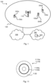
- Fig. 1 is a schematic diagram illustrating a communications system 100 where embodiments presented herein can be applied.
- the communications system 100 is assumed to provide services for group communication and may hence be regarded as a group communications system.
- the group communications system 100 is, according to some aspects, a push to talk (PTT) system.
- PTT push to talk
- the group communication could thus comprise a push to talk service.
- the communications system 100 comprises a radio access network (as represented by its radio coverage area 120), a core network 130, and a service network 140.
- the communications system 100 further comprises at least one control node 300 and at least one client node 200a, 200b, 200c.
- Each client node 200a, 200b, 200c could be a mission critical (MC) service client.
- the at least one control node 300 may be provided in, or installed on, at least one radio access network (RAN) node 110 or in another entity or device in the radio access network, in an entity or device of the core network 130, or in an entity or device of the service network 140.
- the at least one control node 300 could implement the functionality of a group communication service application server (GCS AS) and be a MC service server.
- Each client node 200a, 200b, 200c may be hosted by, provided in, or installed on, a respective wireless device 150a, 150b, 150c.
- GCS AS group communication service application server
- the radio access network is operatively connected to the core network 130 which in turn is operatively connected to the service network 140.
- the at least one radio access network node 110 thereby enables the wireless devices 150a, 150b, 150c, and hence the client nodes 200a, 200b, 200c, to access services and exchange data as provided by the service network 140. It is appreciated that core network 130 and the service network 140 can be implemented on a common platform, i.e., not necessarily on separate hardware.
- wireless devices 150a, 150b, 150c include, but are not limited to, mobile stations, mobile phones, handsets, wireless local loop phones, user equipment (UE), smartphones, laptop computers, and tablet computers.
- radio access network nodes 110 include, but are not limited to, radio base stations, base transceiver stations, node Bs, evolved node Bs, and access points.
- the communications system 100 may comprise a plurality of radio access network nodes 110, each providing network access to a plurality of wireless devices 150a, 150b, 150c.
- the herein disclosed embodiments are not limited to any particular number of radio access network nodes 110, client nodes 200a, 200b, 200c, or wireless devices 150a, 150b, 150c.
- a broadcast technology such as MBMS.
- MBMS allows group communication data to be broadcasted while the wireless devices 150a, 150b, 150c are in idle mode, i.e. only listening to the broadcasted data.
- the radio access network may suspend MBMS bearers without sending any MBMS bearer suspension decision information to the control node 300.
- MBMS bearer suspension is described in 3GPP TS 36.300 v14.0.0.
- client nodes 200a, 200b, 200c can be configured to initiate unicast transmission, whereas the remaining the client nodes 200a, 200b, 200c could be configured to refrain from initiating unicast transmission.
- some client nodes 200a, 200b, 200c could be suspended by the control node 300 from initiating unicast transmission.
- this could lead to uncertainties whether a particular client nodes 200a, 200b, 200c should initiate uncast transmission or not.
- control node 300 instructs the client nodes 200a, 200b, 200c whether or not the client nodes 200a, 200b, 200c is to report service interruption.
- the instruction thereby causes only a subset of all client nodes 200a, 200b, 200c to report bearer failure in cases when the multicast bearer failure is caused by a network issue.
- the embodiments disclosed herein in particular relate to mechanisms for service interruption reporting of a multicast bearer for group communications.
- a client node 200a In order to obtain such mechanisms there is provided a client node 200a, a method performed by the client node 200a, a computer program product comprising code, for example in the form of a computer program, that when run on processing circuitry of the client node 200a, causes the client node 200a to perform the method.
- a control node 300 In order to obtain such mechanisms there is further provided a control node 300, a method performed by the control node 300, and a computer program product comprising code, for example in the form of a computer program, that when run on processing circuitry of the control node 300, causes the control node 300 to perform the method.
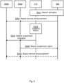
- Figs. 2 and 3 are flow charts illustrating embodiments of methods for service interruption reporting of a multicast bearer for group communications as performed by the client node 200a.
- Figs. 4 and 5 are flow charts illustrating embodiments of methods for service interruption reporting of a multicast bearer for group communications as performed by the control node 300.
- the methods are advantageously provided as computer programs 1120a, 1120b (see, Fig. 11 below).
- FIG. 2 illustrating a method for service interruption reporting of a multicast bearer for group communications as performed by the client node 200a according to an embodiment.
- the control node 300 in step S202 instructs the client nodes 200a, 200b, 200c whether or not to report service interruption of the multicast bearer.
- the client node 200a is configured to perform step S102: S102: The client node 200a obtains instruction from the control node 300 of the multicast bearer. The instruction instructs whether or not the client node 200a is to report service interruption of the multicast bearer.
- the instruction obtained in step S102 could explicitly instruct the client node 200a to report the service interruption to the control node 300.
- the client node 200a could be configured to assume that the service interruption is to be reported to the sender of the instruction, namely the control node 300.
- the client node 200a is configured to perform step S108: S108: The client node 200a detects service interruption of the multicast bearer.
- Such a service interruption could be detected by all client nodes 200a, 200b, 200c listening to the multicast bearer. But according to the instruction obtained in step S102 not all client nodes 200a, 200b, 200c are to report the service interruption to the control node 300. Particularly, the client node 200a is configured to report the service interruption according to step S110: S110: The client node 200a selectively reports the service interruption to the control node 300 in accordance with the instruction.
- the client node 200a reports the service interruption if the instruction obtained in step S102 instructs the client node 200a to do so and refrains from such reporting if the instruction obtained in step S102 instructs the client node 200a to not report the service interruption. That is, the instruction could instruct not only those client nodes that are to report the service interruption to actually do so, but also to instruct those client nodes that are not to report the service interruption to actually not to report the service interruption.
- the instruction could instruct not only those client nodes that are to report the service interruption to actually do so, but also to instruct those client nodes that are not to report the service interruption to actually not to report the service interruption.
- all client nodes 200a, 200b, 200c may obtain the instructions in step S102, not all client nodes 200a, 200b, 200c will report the service interruption in step S110.
- Embodiments relating to further details of service interruption reporting of a multicast bearer for group communications as performed by the client node 200a will now be disclosed.
- Fig. 3 illustrating methods for service interruption reporting of a multicast bearer for group communications as performed by the client node 200a according to further embodiments. It is assumed that steps S102, S108, S110 are performed as described above with reference to Fig. 2 and a thus repeated description thereof is therefore omitted.
- the client node 200a could obtain the instruction in step S102.
- the instruction is obtained during a service announcement procedure of the multicast bearer.
- the instruction is obtained in a service announcement update of the multicast bearer, where the service announcement update could be based on a listening report.
- the service announcement procedure and the listening report could be performed as discussed in 3GPP TS 23.179 v13.3.0 (where the listening report is called MBMS listening status report).
- the instruction in step S102 could be obtained as a request for an MBMS suspension report and the service announcement procedure could be an MBMS bearer announcement procedure.
- the client node 200a could report the service interruption in step S110.
- the service interruption is reported in a multicast bearer suspension report.
- the service interruption is reported in a multicast bearer in a listening report.
- the instruction obtained in step S102 could instruct the client node 200a to report the service interruption in an MBMS suspension report.
- all client nodes 200a, 200b, 200c listening to the multicast bearer could report their current location to the control node 300.
- location information could by the control node 300 be used to determine which client nodes that are to report the service interruption.
- the instruction further instructs the client node 200a to report location and the client node 200a is configured to perform step S104:
- control node 300a could be ways for the control node 300a to keep track of those client nodes 200a that are instructed to report service interruption of the multicast bearer.
- the client node 200a continuously sends keepalive (KA) signals to the control node 300.
- KA signals could by the control node 300 be used to verify that the client node 200a still listens to the multicast bearer and hence still is capable of detecting service interruption of the multicast bearer.
- a KA signal can be any signal which enables the control node 300 to verify that the client node 200a is still capable of detecting service interruption of the multicast bearer.
- the instruction further instructs the client node 200a to send KA signals if the client node 200a is instructed to report service interruption of the multicast bearer and the client node 200a is configured to perform step S106:
- Absence of KA signals from a client node 200a instructed to send KA signals could by the control node 300 be used to conclude that the client node 200a no longer is capable of detecting service interruption of the multicast bearer, and/or is no longer able to report service interruption.
- the client node 200a reports to the control node 300 if the client node 200a is shut down or is about to be shut down. Such a report of the shutdown of the client node 200a could by the control node 300 be used to conclude that the client node 200a no longer is capable of detecting service interruption of the multicast bearer and/or is no longer able to report service interruption.
- the instruction further instructs the client node 200a to report shutdown if the client node 200a is instructed to report service interruption of the multicast bearer and the client node 200a is configured to perform step S112: S112:
- the client node 200a selectively reports shutdown of the client node 200a to the control node 300 in accordance with the instruction. Selectively report here has the same understanding as the above disclosed selectively report in step S110.
- Shutdown is here to be construed broadly to incorporate any configuration or re-configuration of the client node 200a which is preventing the client node 200a from detecting service interruption of the multicast bearer and/or from reporting service interruption. Examples include, e.g., selectively disabling a radio transceiver or the wireless device 150a, for example by setting the wireless device 160 in so called flight mode, or knowingly entering a location with poor or non-existent network coverage, such as going underground or into a tunnel (with the wireless device 150a).
- the control node 300 could rely on receiving KA signals from the client node 200a as disclosed above and hence be configured to assume that the client node 200a is shut off if KA signals are no longer sent from the client node 200a.
- the client node 200a receives a suspension indication from the radio access network node 110.
- the client node 200a is configured to detect the service interruption of the multicast bearer in step S108 by performing step S108a: S108a: The client node 200a obtains a suspension indication of the multicast bearer from a radio access network node 110 of the multicast bearer.
- Step S108a could be performed as part of step S108.
- the suspension indication could be included in a scheduling information packet.
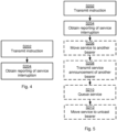
- Fig. 4 illustrating a method for service interruption reporting of a multicast bearer for group communications as performed by the control node 300 according to an embodiment.
- control node 300 instructs the client nodes 200a, 200b, 200c whether or not the client nodes 200a, 200b, 200c is to report service interruption.
- control node 300 is configured to perform step S202: S202: The control node 300 transmits instruction whether or not a client node 200a, 200b, 200c listening to the multicast bearer is to report service interruption of the multicast bearer.
- the instruction could comprise identification information, such an address, an identity, or any other information that uniquely could be used to identify a subset of those client nodes 200a, 200b, 200c that are to report service interruption of the multicast bearer. This could help the control node 300 to keep track of which client nodes 200a, 200b, 200c that are to report service interruption of the multicast bearer and which client nodes 200a, 200b, 200c that are to not report service interruption of the multicast bearer.
- identification information such an address, an identity, or any other information that uniquely could be used to identify a subset of those client nodes 200a, 200b, 200c that are to report service interruption of the multicast bearer.
- the client node 200a in a step S110 reports the service interruption to the control node 300.
- the control node 300 is configured to perform step S204: S204: The control node 300 obtains reporting of service interruption of the multicast bearer from the client node 200a instructed to report failure of the multicast bearer.
- Embodiments relating to further details of service interruption reporting of a multicast bearer for group communications as performed by the control node 300 will now be disclosed.
- Fig. 5 illustrating methods for service interruption reporting of a multicast bearer for group communications as performed by the control node 300 according to further embodiments. It is assumed that steps S202, S204 are performed as described above with reference to Fig. 4 and a thus repeated description thereof is therefore omitted.
- the control node 300 could be transmitted during a service announcement procedure of the multicast bearer or in a service announcement update of the multicast bearer.
- the instruction is broadcast during a service announcement procedure of the multicast bearer or in a service announcement update of the multicast bearer.
- the service announcement provides information to the client nodes 200a, 200b, 200c on the identity of the multicast bearer and how to receive the service over the multicast bearer.
- the multicast bearer service announcement message may be transmitted by a unicast transmission to each client node 200a, 200b, 200c or in a broadcast message to all client nodes 200a, 200b, 200c in the radio coverage area 120.
- only subset of the client nodes 200a, 200b, 200c are to report the service interruption.
- the instruction instructs only a selected subset of client nodes 200a, 200b, 200c to report service interruption of the multicast bearer.
- the control node 300 may thus be configured to transmitting the instruction in step S202 to a subset of all the client nodes 200a, 200b, 200c.Client nodes that are not part of the subset are thus not to report the service interruption.
- control node 300 could be different ways for the control node 300 to select how many client nodes 200a, 200b, 200c are to be members of the subset.
- the number of members in the subset is based on the total number of client nodes 200a, 200b, 200c.
- the number of members of the selected subset is based on the total number of client nodes 200a, 200b, 200c listening to the multicast bearer.
- the subset could comprise of a fixed percentage, such as in the range of 10%, of the total number of client nodes 200a, 200b, 200c listening to the multicast bearer.
- control node 300 could select which client nodes 200a, 200b, 200c are to be members of the subset. Consideration could be taken to the location of the client nodes 200a, 200b, 200c, since location of the client nodes 200a, 200b, 200c could be dynamically changed. According to some aspects which client nodes 200a, 200b, 200c to be members of the subset is therefore based on the service area (e.g., based on location information of the client nodes 200a, 200b, 200c as reported by the client nodes 200a, 200b, 200c in step S104).
- the members of the selected subset are selected based on location information as obtained by the control node 300 from the client nodes 200a, 200b, 200c.
- the control node 300 could be configured to transmit the instruction as in step S202 upon the subset having been updated.
- control node 300 could reevaluate the subset of client nodes 200a, 200b, 200c based on the location information reported from the client nodes 200a, 200b, 200c in step S104 which thus is dynamically updated when the client nodes 200a, 200b, 200c move. That is, according to an embodiment the control node 300 is configured to update the subset based on a pre-defined set of rules.
- One such rule could be based on the location of the client nodes 200a, 200b, 200c listening to the multicast bearer.
- the members of the selected subset are randomly selected (out of the client nodes 200a, 200b, 200c listening to the multicast bearer).
- another rule could be that the members of the selected subset are randomly selected when the subset of client nodes 200a, 200b, 200c is updated.
- Another rule could be based on any combination of the rules mentioned above.
- Embodiments relating to mechanisms for the control node 300 to keep track of which client nodes 200a, 200b, 200c are listening to the multicast bearer have been disclosed above.
- control node 300 upon having obtained reporting of the service interruption in step S204.
- control node 300 responds to the reporting by moving the service of the multicast bearer to another bearer.
- a service is sent on the multicast bearer and the control node 300 is configured to perform steps S206, S208 upon having obtained the reporting of service interruption in step S204:
- the so-called another bearer could be a multicast bearer or a unicast bearer.
- Step S208 could be omitted if the bearer is a unicast bearer.
- control node 300 responds to the reporting by queuing the service until the multicast bearer is resumed.
- a service is sent on the multicast bearer and the control node 300 is configured to perform step S210 upon having obtained the reporting of service interruption in step S204:
- control node 300 responds to the reporting by selecting to suspend certain low prioritized services and setting up unicast bearers only to high priority services.
- a service is sent on the multicast bearer and the control node 300 is configured to perform step S212 upon having obtained the reporting of service interruption in step S204: S212: The control node 300 moves the service to a unicast bearer.
- the service interruption is caused by bearer failure.
- the service interruption is caused by multicast bearer failure detected by the client nodes 200a, 200b, 200c.
- the multicast bearer could be suspended or pre-empted. If the multicast bearer is subjected to strong interference then the client node 200a and/or wireless device 150a could just report this as experiencing a network performance degradation in a listening report.
- multicast bearer is an MBMS bearer.
- Fig. 7 schematically illustrates, in terms of a number of functional units, the components of a client node 200a according to an embodiment.
- Processing circuitry 210 is provided using any combination of one or more of a suitable central processing unit (CPU), multiprocessor, microcontroller, digital signal processor (DSP), etc., capable of executing software instructions stored in a computer program product 1110a (as in Fig. 11 ), e.g. in the form of a storage medium 230.
- the processing circuitry 210 may further be provided as at least one application specific integrated circuit (ASIC), or field programmable gate array (FPGA).
- ASIC application specific integrated circuit
- FPGA field programmable gate array
- the processing circuitry 210 is configured to cause the client node 200a to perform a set of operations, or steps, S102-S112, as disclosed above.
- the storage medium 230 may store the set of operations
- the processing circuitry 210 may be configured to retrieve the set of operations from the storage medium 230 to cause the client node 200a to perform the set of operations.
- the set of operations may be provided as a set of executable instructions.
- the processing circuitry 210 is thereby arranged to execute methods as herein disclosed.
- the storage medium 230 may also comprise persistent storage, which, for example, can be any single one or combination of magnetic memory, optical memory, solid state memory or even remotely mounted memory.
- the client node 200a may further comprise a communications interface 220 for communications at least with the control node 300.
- the communications interface 220 may comprise one or more transmitters and receivers, comprising analogue and digital components.
- the processing circuitry 210 controls the general operation of the client node 200a e.g. by sending data and control signals to the communications interface 220 and the storage medium 230, by receiving data and reports from the communications interface 220, and by retrieving data and instructions from the storage medium 230.
- Other components, as well as the related functionality, of the client node 200a are omitted in order not to obscure the concepts presented herein.
- Fig. 8 schematically illustrates, in terms of a number of functional modules, the components of a client node 200a according to an embodiment.
- the client node 200a of Fig. 8 comprises a number of functional modules; an obtain module 210a configured to perform step S102, a detect module 210d configured to perform step S108, and a report module 210f configured to perform step S110.
- the client node 200a of Fig. 8 may further comprise a number of optional functional modules, such as any of a report module 210b configured to perform step S104, a send module 210c configured to perform step S106, an obtain module 210e configured to perform step S108a, and a report module 210g configured to perform step S112.
- each functional module 210a-210g maybe implemented in hardware or in software.
- one or more or all functional modules 210a-210g may be implemented by the processing circuitry 210, possibly in cooperation with functional units 220 and/or 230.
- the processing circuitry 210 may thus be arranged to from the storage medium 230 fetch instructions as provided by a functional module 210a-210g and to execute these instructions, thereby performing any steps of the client node 200a as disclosed herein.
- each functional module 210a-210g may in one embodiment be implemented only in hardware or and in another embodiment with the help of software, i.e., the latter embodiment having computer program instructions stored on the storage medium 230 which when run on the processing circuitry makes the client node 200a perform the corresponding steps mentioned above in conjunction with Figs. 2 and 3 .
- the modules correspond to parts of a computer program, they do not need to be separate modules therein, but the way in which they are implemented in software is dependent on the programming language used.
- one or more or all functional modules 210a-210g may be implemented by the processing circuitry 210, possibly in cooperation with functional units 220 and/or 230.
- the processing circuitry 210 may thus be configured to from the storage medium 230 fetch instructions as provided by a functional module 210a-210g and to execute these instructions, thereby performing any steps as disclosed herein.
- the client node 200a may be provided as a standalone device or as a part of at least one further device.
- the client node 200a maybe hosted by, provided in, or installed on a wireless device 150a.
- Fig. 9 schematically illustrates, in terms of a number of functional units, the components of a control node 300 according to an embodiment.
- Processing circuitry 310 is provided using any combination of one or more of a suitable central processing unit (CPU), multiprocessor, microcontroller, digital signal processor (DSP), etc., capable of executing software instructions stored in a computer program product 1110b (as in Fig. 11 ), e.g. in the form of a storage medium 330.
- the processing circuitry 310 may further be provided as at least one application specific integrated circuit (ASIC), or field programmable gate array (FPGA).
- ASIC application specific integrated circuit
- FPGA field programmable gate array
- the processing circuitry 310 is configured to cause the control node 300 to perform a set of operations, or steps, S202-S212, as disclosed above.
- the storage medium 330 may store the set of operations
- the processing circuitry 310 maybe configured to retrieve the set of operations from the storage medium 330 to cause the control node 300 to perform the set of operations.
- the set of operations may be provided as a set of executable instructions.
- the processing circuitry 310 is thereby arranged to execute methods as herein disclosed.
- the storage medium 330 may also comprise persistent storage, which, for example, can be any single one or combination of magnetic memory, optical memory, solid state memory or even remotely mounted memory.
- the control node 300 may further comprise a communications interface 320 for communications at least with the client nodes 200a, 200b, 200c.
- the communications interface 320 may comprise one or more transmitters and receivers, comprising analogue and digital components.
- the processing circuitry 310 controls the general operation of the control node 300 e.g. by sending data and control signals to the communications interface 320 and the storage medium 330, by receiving data and reports from the communications interface 320, and by retrieving data and instructions from the storage medium 330.
- Other components, as well as the related functionality, of the control node 300 are omitted in order not to obscure the concepts presented herein.
- Fig. 10 schematically illustrates, in terms of a number of functional modules, the components of a control node 300 according to an embodiment.
- the control node 300 of Fig. 10 comprises a number of functional modules; a transmit module 310a configured to perform step S202, and an obtain module 310b configured to perform step S204.
- the control node 300 of Fig. 10 may further comprise a number of optional functional modules, such as any of a move module 3100 configured to perform step S206, a transmit module 310d configured to perform step S208, a queue module 3100 configured to perform step S210, and a move module 310f configured to perform step S212.
- each functional module 310a-310f may be implemented in hardware or in software.
- one or more or all functional modules 310a-310f may be implemented by the processing circuitry 310, possibly in cooperation with functional units 320 and/or 330.
- the processing circuitry 310 may thus be arranged to from the storage medium 330 fetch instructions as provided by a functional module 310a-310f and to execute these instructions, thereby performing any steps of the control node 300 as disclosed herein.
- each functional module 310a-310f may in one embodiment be implemented only in hardware or and in another embodiment with the help of software, i.e., the latter embodiment having computer program instructions stored on the storage medium 330 which when run on the processing circuitry makes the control node 300 perform the corresponding steps mentioned above in conjunction with Figs. 4 and 5 .
- the modules correspond to parts of a computer program, they do not need to be separate modules therein, but the way in which they are implemented in software is dependent on the programming language used.
- one or more or all functional modules 310a-310f may be implemented by the processing circuitry 310, possibly in cooperation with functional units 320 and/or 330.
- the processing circuitry 310 may thus be configured to from the storage medium 330 fetch instructions as provided by a functional module 310a-310f and to execute these instructions, thereby performing any steps as disclosed herein.
- the control node 300 maybe provided as a standalone device or as a part of at least one further device.
- the control node 300 maybe hosted by, provided in, or installed on a GCS AS or an MC service server.
- Fig. 11 shows one example of a computer program product 1110a, 1110b comprising computer readable means 1130.
- a computer program 1120a can be stored, which computer program 1120a can cause the processing circuitry 210 and thereto operatively coupled entities and devices, such as the communications interface 220 and the storage medium 230, to execute methods according to embodiments described herein.
- the computer program 1120a and/or computer program product 1110a may thus provide means for performing any steps of the client node 200a as herein disclosed.
- a computer program 1120b can be stored, which computer program 1120b can cause the processing circuitry 310 and thereto operatively coupled entities and devices, such as the communications interface 320 and the storage medium 330, to execute methods according to embodiments described herein.
- the computer program 1120b and/or computer program product 1110b may thus provide means for performing any steps of the control node 300 as herein disclosed.
- the computer program product 1110a, 1110b is illustrated as an optical disc, such as a CD (compact disc) or a DVD (digital versatile disc) or a Blu-Ray disc.
- the computer program product 1110a, 1110b could also be embodied as a memory, such as a random access memory (RAM), a read-only memory (ROM), an erasable programmable read-only memory (EPROM), or an electrically erasable programmable read-only memory (EEPROM) and more particularly as a non-volatile storage medium of a device in an external memory such as a USB (Universal Serial Bus) memory or a Flash memory, such as a compact Flash memory.
- RAM random access memory
- ROM read-only memory
- EPROM erasable programmable read-only memory
- EEPROM electrically erasable programmable read-only memory
- the computer program 1120a, 1120b is here schematically shown as a track on the depicted optical disk, the computer program 1120a,
Landscapes
- Engineering & Computer Science (AREA)
- Computer Networks & Wireless Communication (AREA)
- Signal Processing (AREA)
- Multimedia (AREA)
- Environmental & Geological Engineering (AREA)
- Mobile Radio Communication Systems (AREA)
- Data Exchanges In Wide-Area Networks (AREA)
- Telephone Function (AREA)
- Telephonic Communication Services (AREA)
Claims (8)
- Verfahren zum Melden einer Dienstunterbrechung eines Multicast-Trägers für Gruppenkommunikationen, wobei das Verfahren durch einen Client-Knoten (220a) durchgeführt wird, der auf einer drahtlosen Vorrichtung (150a) gehostet wird, wobei das Verfahren Folgendes umfasst:Erlangen (S102) einer Anweisung von einem Steuerknoten (300) des Multicast-Trägers, wobei die Anweisung anweist, ob der Client-Knoten (220a) eine Dienstunterbrechung des Multicast-Trägers zu melden hat oder nicht;Detektieren (S108) einer Dienstunterbrechung des Multicast-Trägers; undselektives Melden (S110) der Dienstunterbrechung an den Steuerknoten (300) gemäß der Anweisung, sodass der Client-Knoten (200a) die Dienstunterbrechung meldet, wenn die erlangte Anweisung den Client-Knoten dazu anweist, dies zu tun, und ein derartiges Melden unterlässt, wenn die erlangte Anweisung den Client-Knoten dazu anweist, die Dienstunterbrechung nicht zu melden.
- Verfahren nach Anspruch 1, wobei die Anweisung während einer Dienstmitteilungsprozedur des Multicast-Trägers erlangt wird.
- Verfahren nach einem der vorhergehenden Ansprüche, wobei das Detektieren einer Dienstunterbrechung des Multicast-Trägers Folgendes umfasst:
Erlangen (S108a) einer Suspendierungsangabe des Multicast-Trägers von einem Funkzugangsnetzwerkknoten (110) des Multicast-Trägers. - Verfahren nach einem der vorhergehenden Ansprüche, wobei die Dienstunterbrechung in einer Suspendierungsmeldung des Multicast-Trägers oder in einer Abhörmeldung gemeldet wird.
- Verfahren nach einem der vorhergehenden Ansprüche, wobei die Anweisung den Client-Knoten (200a) ferner dazu anweist, den Standort zu melden, wobei das Verfahren ferner Folgendes umfasst:
Melden (S104) des Standorts des Client-Knoten (200a) an den Steuerknoten (300) gemäß der Anweisung. - Verfahren nach einem der vorhergehenden Ansprüche, wobei die Anweisung den Client-Knoten (200a) ferner dazu anweist, Keepalive-Signale, KA-Signale, zu senden, wenn der Client-Knoten (200a) dazu angewiesen wird, eine Dienstunterbrechung des Multicast-Trägers zu melden, wobei das Verfahren ferner Folgendes umfasst:
selektives Senden (S106) des KA-Signals an den Steuerknoten (300) gemäß der Anweisung. - Verfahren nach einem der vorhergehenden Ansprüche, wobei die Anweisung den Client-Knoten (200a) ferner dazu anweist, eine Abschaltung zu melden, wenn der Client-Knoten (200a) dazu angewiesen wird, eine Dienstunterbrechung des Multicast-Trägers zu melden, wobei das Verfahren ferner Folgendes umfasst:
selektives Melden (S112) der Abschaltung des Client-Knotens (200a) an den Steuerknoten (300) gemäß der Anweisung. - Client-Knoten (200a) zum Melden einer Dienstunterbrechung eines Multicast-Trägers für Gruppenkommunikationen, wobei der Client-Knoten (200a) auf einer drahtlosen Vorrichtung (150a) gehostet wird, umfassend:eine Verarbeitungsschaltung (210); undein Speichermedium (230), auf dem Anweisungen gespeichert sind, die bei Ausführung durch die Verarbeitungsschaltung (210) den Client-Knoten (200a) zu Folgendem veranlassen:Erlangen einer Anweisung von einem Steuerknoten (300) des Multicast-Trägers, wobei die Anweisung anweist, ob der Client-Knoten (200a) eine Dienstunterbrechung des Multicast-Trägers zu melden hat oder nicht;Detektieren einer Dienstunterbrechung des Multicast-Trägers; undselektives Melden der Dienstunterbrechung an den Steuerknoten (300) gemäß der Anweisung, sodass der Client-Knoten (200a) die Dienstunterbrechung meldet, wenn die erlange Anweisung den Client-Knoten dazu anweist, dies zu tun, und ein derartiges Melden unterlässt, wenn die erlangte Anweisung den Client-Knoten dazu anweist, die Dienstunterbrechung nicht zu melden.
Priority Applications (2)
| Application Number | Priority Date | Filing Date | Title |
|---|---|---|---|
| EP20201512.9A EP3800834B1 (de) | 2016-11-01 | 2016-11-01 | Meldung von dienstunterbrechungen |
| ES20201512T ES2966691T3 (es) | 2016-11-01 | 2016-11-01 | Informe de interrupción del servicio |
Applications Claiming Priority (4)
| Application Number | Priority Date | Filing Date | Title |
|---|---|---|---|
| EP16790962.1A EP3241305B1 (de) | 2016-11-01 | 2016-11-01 | Dienstunterbrechungsbenachrichtigung |
| EP20201512.9A EP3800834B1 (de) | 2016-11-01 | 2016-11-01 | Meldung von dienstunterbrechungen |
| PCT/EP2016/076275 WO2017129280A1 (en) | 2016-11-01 | 2016-11-01 | Service interruption reporting |
| EP18209337.7A EP3484099B1 (de) | 2016-11-01 | 2016-11-01 | Dienstunterbrechungsbenachrichtigung |
Related Parent Applications (4)
| Application Number | Title | Priority Date | Filing Date |
|---|---|---|---|
| EP18209337.7A Division EP3484099B1 (de) | 2016-11-01 | 2016-11-01 | Dienstunterbrechungsbenachrichtigung |
| EP18209337.7A Division-Into EP3484099B1 (de) | 2016-11-01 | 2016-11-01 | Dienstunterbrechungsbenachrichtigung |
| EP16790962.1A Division EP3241305B1 (de) | 2016-11-01 | 2016-11-01 | Dienstunterbrechungsbenachrichtigung |
| PCT/EP2016/076275 Previously-Filed-Application WO2017129280A1 (en) | 2016-11-01 | 2016-11-01 | Service interruption reporting |
Publications (3)
| Publication Number | Publication Date |
|---|---|
| EP3800834A1 EP3800834A1 (de) | 2021-04-07 |
| EP3800834B1 true EP3800834B1 (de) | 2023-10-18 |
| EP3800834C0 EP3800834C0 (de) | 2023-10-18 |
Family
ID=57233433
Family Applications (3)
| Application Number | Title | Priority Date | Filing Date |
|---|---|---|---|
| EP18209337.7A Active EP3484099B1 (de) | 2016-11-01 | 2016-11-01 | Dienstunterbrechungsbenachrichtigung |
| EP16790962.1A Active EP3241305B1 (de) | 2016-11-01 | 2016-11-01 | Dienstunterbrechungsbenachrichtigung |
| EP20201512.9A Active EP3800834B1 (de) | 2016-11-01 | 2016-11-01 | Meldung von dienstunterbrechungen |
Family Applications Before (2)
| Application Number | Title | Priority Date | Filing Date |
|---|---|---|---|
| EP18209337.7A Active EP3484099B1 (de) | 2016-11-01 | 2016-11-01 | Dienstunterbrechungsbenachrichtigung |
| EP16790962.1A Active EP3241305B1 (de) | 2016-11-01 | 2016-11-01 | Dienstunterbrechungsbenachrichtigung |
Country Status (12)
| Country | Link |
|---|---|
| US (3) | US10348552B2 (de) |
| EP (3) | EP3484099B1 (de) |
| JP (1) | JP6545803B2 (de) |
| KR (1) | KR102174043B1 (de) |
| CN (2) | CN112073205B (de) |
| AR (1) | AR109469A1 (de) |
| BR (1) | BR112019008045B1 (de) |
| DK (1) | DK3484099T3 (de) |
| ES (3) | ES2721505T3 (de) |
| HU (1) | HUE044177T2 (de) |
| PL (1) | PL3484099T3 (de) |
| WO (1) | WO2017129280A1 (de) |
Families Citing this family (2)
| Publication number | Priority date | Publication date | Assignee | Title |
|---|---|---|---|---|
| BR112019008045B1 (pt) * | 2016-11-01 | 2023-12-26 | Telefonaktiebolaget Lm Ericsson (Publ) | Método para relato da interrupção de serviço de uma portadora de difusão seletiva para comunicações em grupo, nó cliente, nó de controle, e, mídias de armazenamento não-transitórias legíveis por computador |
| CN110336680B (zh) * | 2019-06-28 | 2021-07-16 | 苏州浪潮智能科技有限公司 | 一种网络广播控制方法、系统及电子设备和存储介质 |
Family Cites Families (22)
| Publication number | Priority date | Publication date | Assignee | Title |
|---|---|---|---|---|
| GB2406997B (en) * | 2003-10-02 | 2005-10-19 | Nec Technologies | Mobile radio communications device and method of operation and communications system |
| EP1698084A4 (de) * | 2003-12-01 | 2007-04-04 | Interdigital Tech Corp | Verfahren und vorrichtung zur benachrichtigung über unverfügbarkeit von of broadcast/multicast-diensten |
| US8689016B2 (en) * | 2005-12-02 | 2014-04-01 | Google Inc. | Tamper prevention and detection for video provided over a network to a client |
| CN101163260B (zh) * | 2006-10-14 | 2011-04-13 | 华为技术有限公司 | 一种控制承载变化的系统、装置和方法 |
| US8208463B2 (en) * | 2006-10-24 | 2012-06-26 | Cisco Technology, Inc. | Subnet scoped multicast / broadcast packet distribution mechanism over a routed network |
| CN101242569B (zh) * | 2007-02-05 | 2013-03-20 | 中兴通讯股份有限公司 | 一种防止或减少多媒体广播组播服务业务中断的方法 |
| US9686770B2 (en) * | 2010-06-15 | 2017-06-20 | Mediatek Inc. | Methods to support MBMS service continuity and counting and localized MBMS service |
| US8699397B2 (en) * | 2010-07-28 | 2014-04-15 | Interdigital Patent Holdings, Inc. | Method and apparatus for multimedia broadcast multicast services (MBMS) service feedback |
| CN102695129B (zh) | 2011-03-21 | 2018-01-02 | 中兴通讯股份有限公司 | 确定挂起mbms业务重新恢复的方法及装置、用户设备 |
| US9826502B2 (en) * | 2011-07-25 | 2017-11-21 | Qualcomm Incorporated | Managing handoff triggering between unicast and multicast services |
| CN102624565B (zh) * | 2012-03-13 | 2013-11-20 | 中国联合网络通信集团有限公司 | 应用层组播系统中单点故障的处理方法 |
| CN103546826B (zh) * | 2012-07-16 | 2017-07-21 | 上海贝尔股份有限公司 | 视频业务的传输方法和装置 |
| US10646165B2 (en) * | 2013-04-10 | 2020-05-12 | The General Hospital Corporation | Removing eletrophysicologic artifacts from a magnetic resonance imaging system |
| EP3017616B1 (de) * | 2013-07-01 | 2018-12-05 | NEC Corporation | Verfahren zur bereitstellung von multicast-/broadcast-dienstkontinuität für mobile endgeräte |
| US9974090B2 (en) * | 2013-07-03 | 2018-05-15 | Interdigital Patent Holdings, Inc. | EPC enhancements for proximity services |
| US9883355B2 (en) * | 2013-09-26 | 2018-01-30 | Lg Electronics Inc. | Method and apparatus for transmitting interest indication for group communication in wireless communication system |
| WO2015096160A1 (zh) * | 2013-12-27 | 2015-07-02 | 华为技术有限公司 | 一种保持业务连续性的方法及设备 |
| CN104270725B (zh) * | 2014-09-24 | 2018-04-10 | 中兴通讯股份有限公司 | 指示信息的确定、处理以及请求消息的处理方法及装置 |
| EP3001745B1 (de) * | 2014-09-26 | 2019-05-22 | Samsung Electronics Co., Ltd. | Rundfunkressourcenüberlastungssteuerungsverfahren und vorrichtung zur verwendung in einem drahtloskommunikationssystem |
| US9641986B2 (en) * | 2015-04-21 | 2017-05-02 | Qualcomm Incorporated | Prioritization of concurrent inter-frequency/inter-RAT measurement and eMBMS service reception |
| US9781182B2 (en) * | 2015-06-23 | 2017-10-03 | Alcatel Lucent | Monitoring of IP multicast streams within an internet gateway device |
| BR112019008045B1 (pt) * | 2016-11-01 | 2023-12-26 | Telefonaktiebolaget Lm Ericsson (Publ) | Método para relato da interrupção de serviço de uma portadora de difusão seletiva para comunicações em grupo, nó cliente, nó de controle, e, mídias de armazenamento não-transitórias legíveis por computador |
-
2016
- 2016-11-01 BR BR112019008045-7A patent/BR112019008045B1/pt active IP Right Grant
- 2016-11-01 KR KR1020197010906A patent/KR102174043B1/ko active IP Right Grant
- 2016-11-01 CN CN202010979360.6A patent/CN112073205B/zh active Active
- 2016-11-01 HU HUE16790962 patent/HUE044177T2/hu unknown
- 2016-11-01 JP JP2017535377A patent/JP6545803B2/ja active Active
- 2016-11-01 PL PL18209337T patent/PL3484099T3/pl unknown
- 2016-11-01 ES ES16790962T patent/ES2721505T3/es active Active
- 2016-11-01 ES ES18209337T patent/ES2860983T3/es active Active
- 2016-11-01 EP EP18209337.7A patent/EP3484099B1/de active Active
- 2016-11-01 ES ES20201512T patent/ES2966691T3/es active Active
- 2016-11-01 US US15/539,178 patent/US10348552B2/en active Active
- 2016-11-01 EP EP16790962.1A patent/EP3241305B1/de active Active
- 2016-11-01 CN CN201680012320.6A patent/CN108271431B/zh active Active
- 2016-11-01 DK DK18209337.7T patent/DK3484099T3/da active
- 2016-11-01 WO PCT/EP2016/076275 patent/WO2017129280A1/en active Application Filing
- 2016-11-01 EP EP20201512.9A patent/EP3800834B1/de active Active
-
2017
- 2017-08-30 AR ARP170102404A patent/AR109469A1/es active IP Right Grant
-
2019
- 2019-04-24 US US16/392,811 patent/US10848369B2/en active Active
-
2020
- 2020-10-12 US US17/068,232 patent/US11611465B2/en active Active
Also Published As
| Publication number | Publication date |
|---|---|
| JP6545803B2 (ja) | 2019-07-17 |
| AR109469A1 (es) | 2018-12-12 |
| ES2966691T3 (es) | 2024-04-23 |
| KR102174043B1 (ko) | 2020-11-04 |
| EP3241305A1 (de) | 2017-11-08 |
| HUE044177T2 (hu) | 2019-10-28 |
| EP3241305B1 (de) | 2019-01-30 |
| EP3484099A1 (de) | 2019-05-15 |
| KR20190055157A (ko) | 2019-05-22 |
| EP3800834A1 (de) | 2021-04-07 |
| US20180123865A1 (en) | 2018-05-03 |
| JP2018524828A (ja) | 2018-08-30 |
| BR112019008045A2 (pt) | 2019-07-02 |
| ES2860983T3 (es) | 2021-10-05 |
| CN108271431B (zh) | 2020-10-23 |
| ES2721505T3 (es) | 2019-08-01 |
| WO2017129280A1 (en) | 2017-08-03 |
| CN112073205B (zh) | 2024-05-14 |
| BR112019008045B1 (pt) | 2023-12-26 |
| US20210028972A1 (en) | 2021-01-28 |
| PL3484099T3 (pl) | 2021-07-05 |
| US10848369B2 (en) | 2020-11-24 |
| CN108271431A (zh) | 2018-07-10 |
| US20190253307A1 (en) | 2019-08-15 |
| EP3484099B1 (de) | 2021-01-06 |
| EP3800834C0 (de) | 2023-10-18 |
| DK3484099T3 (da) | 2021-01-18 |
| US10348552B2 (en) | 2019-07-09 |
| US11611465B2 (en) | 2023-03-21 |
| CN112073205A (zh) | 2020-12-11 |
Similar Documents
| Publication | Publication Date | Title |
|---|---|---|
| US11172376B2 (en) | Method and apparatus for selecting and accessing network, and computer storage medium | |
| US11611465B2 (en) | Service interruption reporting | |
| US11140656B2 (en) | Paging in a group communications system | |
| EP3703397B1 (de) | Mbms-träger-handhabung in einem gruppenkommunikationssystem | |
| US10356676B2 (en) | Resource switching method, apparatus, and system | |
| EP3554100B1 (de) | Verfahren und vorrichtung zum erhalt von systemnachrichten, und endgerät | |
| US9763261B2 (en) | Mobile station, communication system, allocation apparatus, and allocation method | |
| WO2015043925A1 (en) | Channel allocation for proximity-based communications in a cluster | |
| WO2015139748A1 (en) | Transmissions in wireless systems |
Legal Events
| Date | Code | Title | Description |
|---|---|---|---|
| PUAI | Public reference made under article 153(3) epc to a published international application that has entered the european phase |
Free format text: ORIGINAL CODE: 0009012 |
|
| STAA | Information on the status of an ep patent application or granted ep patent |
Free format text: STATUS: THE APPLICATION HAS BEEN PUBLISHED |
|
| AC | Divisional application: reference to earlier application |
Ref document number: 3241305 Country of ref document: EP Kind code of ref document: P Ref document number: 3484099 Country of ref document: EP Kind code of ref document: P |
|
| AK | Designated contracting states |
Kind code of ref document: A1 Designated state(s): AL AT BE BG CH CY CZ DE DK EE ES FI FR GB GR HR HU IE IS IT LI LT LU LV MC MK MT NL NO PL PT RO RS SE SI SK SM TR |
|
| STAA | Information on the status of an ep patent application or granted ep patent |
Free format text: STATUS: REQUEST FOR EXAMINATION WAS MADE |
|
| 17P | Request for examination filed |
Effective date: 20211006 |
|
| RBV | Designated contracting states (corrected) |
Designated state(s): AL AT BE BG CH CY CZ DE DK EE ES FI FR GB GR HR HU IE IS IT LI LT LU LV MC MK MT NL NO PL PT RO RS SE SI SK SM TR |
|
| REG | Reference to a national code |
Ref country code: DE Ref legal event code: R079 Ref document number: 602016083611 Country of ref document: DE Free format text: PREVIOUS MAIN CLASS: H04L0012240000 Ipc: H04L0012180000 Ref country code: DE Ref legal event code: R079 Free format text: PREVIOUS MAIN CLASS: H04L0012240000 Ipc: H04L0012180000 |
|
| GRAP | Despatch of communication of intention to grant a patent |
Free format text: ORIGINAL CODE: EPIDOSNIGR1 |
|
| STAA | Information on the status of an ep patent application or granted ep patent |
Free format text: STATUS: GRANT OF PATENT IS INTENDED |
|
| RIC1 | Information provided on ipc code assigned before grant |
Ipc: H04L 41/0681 20220101ALN20230517BHEP Ipc: H04L 43/0823 20220101ALN20230517BHEP Ipc: H04W 4/08 20090101ALI20230517BHEP Ipc: H04L 12/18 20060101AFI20230517BHEP |
|
| INTG | Intention to grant announced |
Effective date: 20230616 |
|
| GRAS | Grant fee paid |
Free format text: ORIGINAL CODE: EPIDOSNIGR3 |
|
| GRAA | (expected) grant |
Free format text: ORIGINAL CODE: 0009210 |
|
| STAA | Information on the status of an ep patent application or granted ep patent |
Free format text: STATUS: THE PATENT HAS BEEN GRANTED |
|
| AC | Divisional application: reference to earlier application |
Ref document number: 3241305 Country of ref document: EP Kind code of ref document: P Ref document number: 3484099 Country of ref document: EP Kind code of ref document: P |
|
| AK | Designated contracting states |
Kind code of ref document: B1 Designated state(s): AL AT BE BG CH CY CZ DE DK EE ES FI FR GB GR HR HU IE IS IT LI LT LU LV MC MK MT NL NO PL PT RO RS SE SI SK SM TR |
|
| REG | Reference to a national code |
Ref country code: GB Ref legal event code: FG4D |
|
| RIN1 | Information on inventor provided before grant (corrected) |
Inventor name: AKESSON, JOAKIM Inventor name: TRAENK, MAGNUS |
|
| REG | Reference to a national code |
Ref country code: CH Ref legal event code: EP |
|
| REG | Reference to a national code |
Ref country code: IE Ref legal event code: FG4D |
|
| REG | Reference to a national code |
Ref country code: DE Ref legal event code: R096 Ref document number: 602016083611 Country of ref document: DE |
|
| U01 | Request for unitary effect filed |
Effective date: 20231101 |
|
| U07 | Unitary effect registered |
Designated state(s): AT BE BG DE DK EE FI FR IT LT LU LV MT NL PT SE SI Effective date: 20231108 |
|
| U20 | Renewal fee paid [unitary effect] |
Year of fee payment: 8 Effective date: 20231127 |
|
| PGFP | Annual fee paid to national office [announced via postgrant information from national office to epo] |
Ref country code: GB Payment date: 20231127 Year of fee payment: 8 |
|
| PGFP | Annual fee paid to national office [announced via postgrant information from national office to epo] |
Ref country code: ES Payment date: 20231201 Year of fee payment: 8 |
|
| PGFP | Annual fee paid to national office [announced via postgrant information from national office to epo] |
Ref country code: TR Payment date: 20231108 Year of fee payment: 8 |
|
| PG25 | Lapsed in a contracting state [announced via postgrant information from national office to epo] |
Ref country code: GR Free format text: LAPSE BECAUSE OF FAILURE TO SUBMIT A TRANSLATION OF THE DESCRIPTION OR TO PAY THE FEE WITHIN THE PRESCRIBED TIME-LIMIT Effective date: 20240119 |
|
| PG25 | Lapsed in a contracting state [announced via postgrant information from national office to epo] |
Ref country code: IS Free format text: LAPSE BECAUSE OF FAILURE TO SUBMIT A TRANSLATION OF THE DESCRIPTION OR TO PAY THE FEE WITHIN THE PRESCRIBED TIME-LIMIT Effective date: 20240218 |
|
| REG | Reference to a national code |
Ref country code: ES Ref legal event code: FG2A Ref document number: 2966691 Country of ref document: ES Kind code of ref document: T3 Effective date: 20240423 |
|
| PG25 | Lapsed in a contracting state [announced via postgrant information from national office to epo] |
Ref country code: IS Free format text: LAPSE BECAUSE OF FAILURE TO SUBMIT A TRANSLATION OF THE DESCRIPTION OR TO PAY THE FEE WITHIN THE PRESCRIBED TIME-LIMIT Effective date: 20240218 Ref country code: GR Free format text: LAPSE BECAUSE OF FAILURE TO SUBMIT A TRANSLATION OF THE DESCRIPTION OR TO PAY THE FEE WITHIN THE PRESCRIBED TIME-LIMIT Effective date: 20240119 |