EP3800738A1 - Electrical terminal - Google Patents
Electrical terminal Download PDFInfo
- Publication number
- EP3800738A1 EP3800738A1 EP20199136.1A EP20199136A EP3800738A1 EP 3800738 A1 EP3800738 A1 EP 3800738A1 EP 20199136 A EP20199136 A EP 20199136A EP 3800738 A1 EP3800738 A1 EP 3800738A1
- Authority
- EP
- European Patent Office
- Prior art keywords
- terminal
- electric wire
- conductor
- connecting part
- graphene film
- Prior art date
- Legal status (The legal status is an assumption and is not a legal conclusion. Google has not performed a legal analysis and makes no representation as to the accuracy of the status listed.)
- Granted
Links
Images





Classifications
-
- H—ELECTRICITY
- H01—ELECTRIC ELEMENTS
- H01R—ELECTRICALLY-CONDUCTIVE CONNECTIONS; STRUCTURAL ASSOCIATIONS OF A PLURALITY OF MUTUALLY-INSULATED ELECTRICAL CONNECTING ELEMENTS; COUPLING DEVICES; CURRENT COLLECTORS
- H01R4/00—Electrically-conductive connections between two or more conductive members in direct contact, i.e. touching one another; Means for effecting or maintaining such contact; Electrically-conductive connections having two or more spaced connecting locations for conductors and using contact members penetrating insulation
- H01R4/58—Electrically-conductive connections between two or more conductive members in direct contact, i.e. touching one another; Means for effecting or maintaining such contact; Electrically-conductive connections having two or more spaced connecting locations for conductors and using contact members penetrating insulation characterised by the form or material of the contacting members
- H01R4/62—Connections between conductors of different materials; Connections between or with aluminium or steel-core aluminium conductors
-
- H—ELECTRICITY
- H01—ELECTRIC ELEMENTS
- H01R—ELECTRICALLY-CONDUCTIVE CONNECTIONS; STRUCTURAL ASSOCIATIONS OF A PLURALITY OF MUTUALLY-INSULATED ELECTRICAL CONNECTING ELEMENTS; COUPLING DEVICES; CURRENT COLLECTORS
- H01R4/00—Electrically-conductive connections between two or more conductive members in direct contact, i.e. touching one another; Means for effecting or maintaining such contact; Electrically-conductive connections having two or more spaced connecting locations for conductors and using contact members penetrating insulation
- H01R4/58—Electrically-conductive connections between two or more conductive members in direct contact, i.e. touching one another; Means for effecting or maintaining such contact; Electrically-conductive connections having two or more spaced connecting locations for conductors and using contact members penetrating insulation characterised by the form or material of the contacting members
-
- H—ELECTRICITY
- H01—ELECTRIC ELEMENTS
- H01R—ELECTRICALLY-CONDUCTIVE CONNECTIONS; STRUCTURAL ASSOCIATIONS OF A PLURALITY OF MUTUALLY-INSULATED ELECTRICAL CONNECTING ELEMENTS; COUPLING DEVICES; CURRENT COLLECTORS
- H01R13/00—Details of coupling devices of the kinds covered by groups H01R12/70 or H01R24/00 - H01R33/00
- H01R13/02—Contact members
- H01R13/03—Contact members characterised by the material, e.g. plating, or coating materials
-
- H—ELECTRICITY
- H01—ELECTRIC ELEMENTS
- H01B—CABLES; CONDUCTORS; INSULATORS; SELECTION OF MATERIALS FOR THEIR CONDUCTIVE, INSULATING OR DIELECTRIC PROPERTIES
- H01B1/00—Conductors or conductive bodies characterised by the conductive materials; Selection of materials as conductors
- H01B1/04—Conductors or conductive bodies characterised by the conductive materials; Selection of materials as conductors mainly consisting of carbon-silicon compounds, carbon or silicon
-
- H—ELECTRICITY
- H01—ELECTRIC ELEMENTS
- H01B—CABLES; CONDUCTORS; INSULATORS; SELECTION OF MATERIALS FOR THEIR CONDUCTIVE, INSULATING OR DIELECTRIC PROPERTIES
- H01B7/00—Insulated conductors or cables characterised by their form
- H01B7/17—Protection against damage caused by external factors, e.g. sheaths or armouring
- H01B7/28—Protection against damage caused by moisture, corrosion, chemical attack or weather
- H01B7/2806—Protection against damage caused by corrosion
-
- H—ELECTRICITY
- H01—ELECTRIC ELEMENTS
- H01R—ELECTRICALLY-CONDUCTIVE CONNECTIONS; STRUCTURAL ASSOCIATIONS OF A PLURALITY OF MUTUALLY-INSULATED ELECTRICAL CONNECTING ELEMENTS; COUPLING DEVICES; CURRENT COLLECTORS
- H01R13/00—Details of coupling devices of the kinds covered by groups H01R12/70 or H01R24/00 - H01R33/00
- H01R13/02—Contact members
- H01R13/04—Pins or blades for co-operation with sockets
-
- H—ELECTRICITY
- H01—ELECTRIC ELEMENTS
- H01R—ELECTRICALLY-CONDUCTIVE CONNECTIONS; STRUCTURAL ASSOCIATIONS OF A PLURALITY OF MUTUALLY-INSULATED ELECTRICAL CONNECTING ELEMENTS; COUPLING DEVICES; CURRENT COLLECTORS
- H01R13/00—Details of coupling devices of the kinds covered by groups H01R12/70 or H01R24/00 - H01R33/00
- H01R13/02—Contact members
- H01R13/10—Sockets for co-operation with pins or blades
- H01R13/11—Resilient sockets
- H01R13/113—Resilient sockets co-operating with pins or blades having a rectangular transverse section
-
- H—ELECTRICITY
- H01—ELECTRIC ELEMENTS
- H01R—ELECTRICALLY-CONDUCTIVE CONNECTIONS; STRUCTURAL ASSOCIATIONS OF A PLURALITY OF MUTUALLY-INSULATED ELECTRICAL CONNECTING ELEMENTS; COUPLING DEVICES; CURRENT COLLECTORS
- H01R4/00—Electrically-conductive connections between two or more conductive members in direct contact, i.e. touching one another; Means for effecting or maintaining such contact; Electrically-conductive connections having two or more spaced connecting locations for conductors and using contact members penetrating insulation
- H01R4/10—Electrically-conductive connections between two or more conductive members in direct contact, i.e. touching one another; Means for effecting or maintaining such contact; Electrically-conductive connections having two or more spaced connecting locations for conductors and using contact members penetrating insulation effected solely by twisting, wrapping, bending, crimping, or other permanent deformation
- H01R4/18—Electrically-conductive connections between two or more conductive members in direct contact, i.e. touching one another; Means for effecting or maintaining such contact; Electrically-conductive connections having two or more spaced connecting locations for conductors and using contact members penetrating insulation effected solely by twisting, wrapping, bending, crimping, or other permanent deformation by crimping
- H01R4/183—Electrically-conductive connections between two or more conductive members in direct contact, i.e. touching one another; Means for effecting or maintaining such contact; Electrically-conductive connections having two or more spaced connecting locations for conductors and using contact members penetrating insulation effected solely by twisting, wrapping, bending, crimping, or other permanent deformation by crimping for cylindrical elongated bodies, e.g. cables having circular cross-section
- H01R4/184—Electrically-conductive connections between two or more conductive members in direct contact, i.e. touching one another; Means for effecting or maintaining such contact; Electrically-conductive connections having two or more spaced connecting locations for conductors and using contact members penetrating insulation effected solely by twisting, wrapping, bending, crimping, or other permanent deformation by crimping for cylindrical elongated bodies, e.g. cables having circular cross-section comprising a U-shaped wire-receiving portion
- H01R4/185—Electrically-conductive connections between two or more conductive members in direct contact, i.e. touching one another; Means for effecting or maintaining such contact; Electrically-conductive connections having two or more spaced connecting locations for conductors and using contact members penetrating insulation effected solely by twisting, wrapping, bending, crimping, or other permanent deformation by crimping for cylindrical elongated bodies, e.g. cables having circular cross-section comprising a U-shaped wire-receiving portion combined with a U-shaped insulation-receiving portion
Definitions
- JP 2019-36499A discloses an electric wire with terminal having an exposed conductor of an electric wire covered with resin so that moisture does not adhere to the contact part of different kind of metal members.
- the electric wire with terminal of JP 2019-36499A is provided with a pair of crimping pieces for crimping the exposed conductor part of the electric wire, and a pair of caulking pieces for caulking the cover of the electric wire.
- the electric wire with terminal has a resin injection port formed therein. Resin injected from the resin injection port infiltrates into a resin filling space from only one side of the resin filling space, preventing air from remaining at the bottom of the resin filling space. Since air is prevented from remaing in the resin filling space when the resin is injected into the resin filling space, the resin effectively infiltrates into the resin filling space. Thus, the electric wire with terminal effectively prevents the occurrence of galvanic corrosion.
- the electric wire with terminal described in JP 2019-36499A needs to cover the contact part of different kind of metals with a resin or the like not to supply the contact part with moisture causing galvanic corrosion. Accordingly, the manufacturing process of the electric wire with terminal becomes complicated, and the manufacturing cost tends to increase. Further, it is necessary to form the terminal into a special shape and to adhere the resin member closely to the metal member without any gap so that moisture does not adhere to the contact part of the different kind of metal members. Due to the restriction on the terminal shape, the degree of freedom in design decreases, and the miniaturization of the terminal tends to be difficult.
- An object of the present invention is to provide a terminal that prevents galvanic corrosion at a contact part of different kind of metals, an electric wire with terminal using the terminal, and an electric connection member.
- a terminal includes a conductor connecting part provided to be electrically connected to a conductor of an electric wire, a terminal connecting part provided to be electrically connected to an opposite terminal, and a graphene film.
- a first surface that is at least a part of the conductor connecting part is formed of a first metal material
- a second surface that is at least a part of the terminal connecting part is formed of a second metal material.
- the graphene film is provided on at least one of an outer surface of the first surface and an outer surface of the second surface.
- the graphene film is provided to be arranged between the first surface and the conductor of the electric wire when the conductor of the electric wire is electrically connected to the conductor connecting part.
- the graphene film is provided to be arranged between the second surface and the surface of the opposite terminal when the opposite terminal is electrically connected to the terminal connecting part.
- the first metal material may be copper, and the third metal material may be aluminum.
- the electric wire with terminal may not have a resin arranged across the terminal and the conductor of the electric wire for covering the terminal and the conductor.
- An electric connection member includes the terminal and the opposite terminal, and the terminal and the opposite terminal are connected to each other.
- the present invention provides a terminal preventing galvanic corrosion at a contact part of different kind of metals, an electric wire with terminal using the terminal, and an electric connection member.
- FIG. 1 is a sectional view of an example of an electric connection member 1 in which the female terminal 100 and the male terminal 200 are connected to each other.
- FIG. 1 when a terminal connecting part 220 of the male terminal 200 is inserted into a terminal connecting part 120 of the female terminal 100, the female terminal 100 and the male terminal 200 are engaged with each other.
- the terminal connecting part 120 of the female terminal 100 and the terminal connecting part 220 of the male terminal 200 are physically and electrically connected to each other.
- At least a part of the surface of the terminal connecting part 120 and at least a part of the surface of the terminal connecting part 220 are electrically conductive, so that an electric wire 150 connected to the female terminal 100 and an electric wire 250 connected to the male terminal 200 are electrically connected through a graphene film 130.
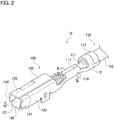
- FIG. 2 is a perspective view of an example of a female electric wire with terminal 10 in which the electric wire 150 is crimped to the female terminal 100 shown in FIG. 1 .
- FIG. 3 is a sectional view taken along line III-III in FIG. 2 .
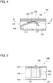
- FIG. 4 is a sectional view taken along line IV-IV in FIG. 2 .
- FIG. 5 is a sectional view taken along line V-V in FIG. 4 .
- the female electric wire with terminal 10 includes the female terminal 100 and the electric wire 150.
- the female terminal 100 includes a conductor connecting part 110, the terminal connecting part 120, and the graphene film 130.
- the conductor connecting part 110 is connected to the terminal connecting part 120.
- the conductor connecting part 110 is provided at one end of the female terminal 100, and the terminal connecting part 120 is provided at the other end of the female terminal 100.
- the conductor connecting part 110 is provided to be electrically connected to a conductor 151 of the electric wire 150.
- the conductor connecting part 110 is provided to crimp the electric wire 150.
- the conductor connecting part 110 includes a conductor crimping part 111 for crimping the conductor 151 of the electric wire 150, and a covering material crimping part 112 for crimping a covering material 152 of the electric wire 150.
- the conductor connecting part 110 crimps and fixes the electric wire 150 to be connected to the female terminal 100.
- the terminal connecting part 120 is provided to be electrically connected to the male terminal 200 (opposite terminal). Specifically, the terminal connecting part 120 is provided to be electrically connected to the terminal connecting part 220 of the male terminal 200.
- the terminal connecting part 120 includes a box body into which the terminal connecting part 220 of the male terminal 200 is inserted, and a plate-like body that extends from a part of the box body into the box body to press the terminal connecting part 220 of the male terminal 200 inserted into the box body with elastic force.
- the plate-like body of the terminal connecting part 120 of the female terminal 100 has an elastic part 126 provided continuously and strongly bent at an end in the longitudinal direction of the third wall part 123, and a sliding part 127 provided continuously and weakly bent at the end of the elastic part 126. That is, the elastic part 126 is provided to have an inner angle smaller than that of the sliding part 127.
- the elastic part 126 is formed of the same material as that of other parts constituting the terminal connecting part 120, such as the third wall part 123, but is provided with a strong elastic force due to its bent shape.
- the sliding part 127 is formed of the same material as that of other parts constituting the terminal connecting part 120, such as the third wall part 123, but is provided with a weak elastic force due to its bent shape.
- At least a part of the conductor connecting part 110 that is a first surface is formed of a first metal material. Since the first metal material is conductive, when the conductor connecting part 110 is mechanically connected to the conductor 151 of the electric wire 150, the conductor connecting part 110 is electrically connected to the conductor 151 of the electric wire 150 through the first metal material.
- At least a part of the terminal connecting part 120 that is a second surface is formed of a second metal material. Since the second metal material is conductive, when the terminal connecting part 120 is mechanically connected to the male terminal 200, the terminal connecting part 120 is electrically connected to the male terminal 200 through the second metal material.
- the first surface may be made of the same material as that of the second surface and continuously formed with the second surface in one body.
- the female terminal 100 may include a substrate.
- the substrate is preferably formed of copper, aluminum, iron, magnesium, an alloy containing one of these metals, or the like, which is conductive.
- a covering layer may or may not be provided on the surface of the substrate.
- the covering layer is, for example, a plating layer.
- the material for forming the covering layer is not limited but preferably gold, silver, copper, tin, nickel, cobalt, or an alloy containing one of these metals.
- the covering layer may be a single layer or multiple layers.
- the thickness of the covering layer is not limited but is, for example, 0.01 to 10 ⁇ m.
- the first metal material may be copper, aluminum, iron, magnesium or an alloy containing one of theses metals, or may be gold, silver, copper, tin, nickel, cobalt, or an alloy containing one of these metals.
- the second metal material may be copper, aluminum, iron, magnesium, or an alloy containing one of these metals, or may be gold, silver, copper, tin, nickel, cobalt, or an alloy containing one of these metals.
- the first metal material and the second metal material may be the same metal material or may be different kind of metal materials.
- the female terminal 100 includes the graphene film 130.
- the graphene film 130 is provided on at least one of the outer surface of the first surface and the outer surface of the second surface.
- the graphene film 130 may be provided on either the outer surface of the first surface or the outer surface of the second surface.
- the graphene film 130 may be provided on both the outer surface of the first surface and the outer surface of the second surface.
- the graphene film 130 may be provided on the entire surface of the female terminal 100.
- Graphene has a planar hexagonal lattice structure formed by sp 2 bonds between carbon atoms.
- the graphene film 130 thus prevents permeation of oxygen and water causing corrosion.
- the graphene film 130 is provided as follows. That is, the graphene film 130 is provided to be arranged between the first surface and the conductor 151 of the electric wire 150 when the conductor 151 of the electric wire 150 is electrically connected to the conductor connecting part 110. The graphene film 130 may be arranged only between the first surface and the conductor 151 of the electric wire 150 when the conductor 151 of the electric wire 150 is electrically connected to the conductor connecting part 110.
- the conductor connecting part 110 and the conductor 151 of the electric wire 150 are electrically connected through the graphene film 130.
- the first surface and the conductor 151 of the electric wire 150 are not in direct physical contact with each other, and the different kind of metal members are not in direct physical contact with each other. Accordingly, even when moisture adheres to the contact part of the conductor connecting part 110 and the conductor 151 of the electric wire 150, galvanic corrosion between these metals is prevented.
- the third metal material may be copper, aluminum, or an alloy of one of these metals.
- the first metal material may be copper, and the third metal material may be aluminum.
- the first metal material may be stainless steel, and the third metal material may be copper.
- the first metal material may be aluminum, and the third metal material may be copper.
- the present disclosure is not limited to the above-described combinations of the metal materials as long as the first metal material and the third metal material have different ionization tendencies.
- the graphene film 130 is provided as follows. That is, the graphene film 130 is provided to be arranged between the second surface and the surface of the male terminal 200 when the male terminal 200 is electrically connected to the terminal connecting part 120. The graphene film 130 may be arranged only between the second surface and the surface of the male terminal 200 when the male terminal 200 is electrically connected to the terminal connecting part 120.
- the female terminal 100 is provided with the graphene film 130, the terminal connecting part 120 and the male terminal 200 are electrically connected through the graphene film 130.
- the second surface and the surface of the male terminal 200 are not in direct physical contact with each other, and the different kind of metal members are not in direct physical contact with each other. Accordingly, even when moisture adheres to the contact part of the terminal connecting part 120 and the male terminal 200, galvanic corrosion between these metals is prevented.
- the provision of the graphene film 130 only to the female terminal 100 prevents galvanic corrosion when the female terminal 100 and the male terminal 200 are connected to each other. That is, galvanic corrosion is prevented by providing the graphene film 300 only to the female terminal 100 without changing the material or plating treatment method of the male terminal 200 installed in the existing apparatus. As a result, without changing the member on the existing apparatus side, the existing apparatus is used only by connecting the female terminal 100.
- the fourth metal material is a material forming the surface of the male terminal 200.
- the male terminal 200 may be formed of the same material as the female terminal 100.
- the male terminal 200 may include a substrate in the same manner as the female terminal 100.
- the substrate of the male terminal 200 may be the same material as that of the female terminal 100.
- a covering layer similar to that of the female terminal 100 may or may not be provided.
- the surface of the male terminal 200 may be included in the substrate or in the covering layer. That is, the fourth metal material may be copper, aluminum, iron, magnesium, or an alloy containing one of these metals, or may be gold, silver, copper, tin, nickel, cobalt, or an alloy containing one of these metals.
- the graphene film 130 may be graphene or a laminate of graphene.
- grain boundaries of graphene are not connected from the surface to the metal surface to prevent the intrusion of oxygen or water and the movement of metal atoms by ionic migration. Accordingly, the number of layers of graphene to be arranged is preferably three or more.
- the thickness of the graphene film 130 is preferably 0.9 nm to 10 ⁇ m from the viewpoint of contact reliability.
- the thickness of the graphene film 130 is obtained by observing the cross section of the graphene film 130 by a scanning electron microscope (SEM) or a transmission electron microscope (TEM) and measuring the thickness.
- the terminal is the female terminal 100 having the conductor connecting part 110, the terminal connecting part 120, and the graphene film 130, and the opposite terminal is the male terminal 200.
- the terminal according to the present embodiment is not limited to the above embodiment. The same effect is obtained, for example, when the terminal is the male terminal 200 having a conductor connecting part 210, a terminal connecting part 220, and a graphene film 230, and the opposite terminal is the female terminal 100.
- FIG. 6 is a front view of an example of an electric wire with terminal 20 in which the electric wire 250 is crimped to the male terminal 200.
- FIG. 7 is a plan view of the electric wire with terminal 20 shown in FIG. 6 .
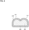
- FIG. 8 is a sectional view taken along line VIII-VIII in FIG. 7 .
- the male terminal 200 includes the conductor connecting part 210, the terminal connecting part 220, and the graphene film 230.
- the conductor connecting part 210 is connected to the terminal connecting part 220.
- the conductor connecting part 210 is provided at one end of the male terminal 200, and the terminal connecting part 220 is provided at the other end of the male terminal 200.
- the conductor connecting part 210 is provided to be electrically connected to a conductor 251 of the electric wire 250.
- the conductor connecting part 110 of the female terminal 100 and the conductor connecting part 210 of the male terminal 200 may have the same shape.
- the conductor connecting part 210 is provided to crimp the electric wire 250.
- the conductor connecting part 210 includes a conductor crimping part 211 for crimping the conductor 251 of the electric wire 250, and a covering material crimping part 212 for crimping a covering material 252 of the electric wire 250.
- the conductor connecting part 210 crimps and fixes the electric wire 250 to be connected to the male terminal 200.
- the terminal connecting part 220 is provided to be electrically connected to the female terminal 100. Specifically, the terminal connecting part 220 is provided to be electrically connected to the terminal connecting part 120 of the female terminal 100.
- At least a part of the conductor connecting part 210 that is a first surface is formed of a first metal material.
- At least a part of the terminal connecting part 220 that is a second surface is formed of a second metal material.
- the male terminal 200 may be formed of the same material as that of the female terminal 100.
- the same material as the above-mentioned fourth metal material may be used for the first metal material.
- the same material as the above-mentioned fourth metal material may be used for the second metal material.
- the graphene film 230 is provided on at least one of the outer surface of the first surface and the outer surface of the second surface.
- the graphene film 230 may be made of the same material as that of the graphene film 130.
- the graphene film 230 is provided as follows. That is, the graphene film 230 is provided to be arranged between the first surface and the conductor 251 of the electric wire 250 when the conductor 251 of the electric wire 250 is electrically connected to the conductor connecting part 210.
- the graphene film 230 is provided as follows. That is, the graphene film 230 is provided to be arranged between the second surface and the surface of the female terminal 100 when the female terminal 100 is electrically connected to the terminal connecting part 220.
- the graphene film 230 prevents galvanic corrosion between different kind of metals.
- a terminal includes a conductor connecting part provided to be electrically connected to a conductor of an electric wire, a terminal connecting part provided to be electrically connected to an opposite terminal, and a graphene film.
- a first surface that is at least a part of the conductor connecting part is formed of a first metal material
- a second surface that is at least a part of the terminal connecting part is formed of a second metal material.
- the graphene film is provided on at least one of an outer surface of the first surface and an outer surface of the second surface.
- the graphene film is provided to be arranged between the first surface and the conductor of the electric wire when the conductor of the electric wire is electrically connected to the conductor connecting part.
- the graphene film is provided to be arranged between the second surface and the surface of the opposite terminal when the opposite terminal is electrically connected to the terminal connecting part. Therefore, the terminal according to the present embodiment prevents galvanic corrosion at the contact part of different kind of metals.
- the electric wire 150 includes the conductor 151 and the covering material 152 covering the conductor 151.
- the conductor 151 As the material of the conductor 151 , a metal having high conductivity may be used.
- the conductor 151 is made of, for example, copper, aluminum, an alloy of one of these metals, or the like. Weight reduction has been demanded for the electric wire 150.
- the conductor 151 is preferably made of aluminum or an aluminum alloy, which is lightweight.
- the covering material 152 for covering the conductor 151 a resin ensuring electrical insulation may be used.
- the covering material 152 is made of an olefin-based resin, for example.
- at least one resin selected from the group consisting of polyethylene (PE), polypropylene (PP), ethylene copolymers, and propylene copolymers may be used as a main component.
- polyvinyl chloride (PVC) may be used as a main component.
- the material of the covering material 152 preferably contains polypropylene or polyvinyl chloride as a main component because of its high flexibility and durability.
- the main component means a component of 50% by mass or more of the whole covering material 152.
- the electric wire with terminal 10 includes the female terminal 100
- the male terminal 200 also prevents galvanic corrosion in the same manner as the female terminal 100 as described above.
- the electric wire with terminal 20 may include the male terminal 200 and the electric wire 250 connected to the male terminal 200.
- the conductor 251 of the electric wire 250 may be electrically connected to the conductor connecting part 210. Even in such an electric wire with terminal 20, galvanic corrosion is prevented in the same manner as described above.
- the electric wire 250 may be the same as the electric wire 150 described above.
- No resin may be arranged across the terminal and the conductor of the electric wire for covering the terminal and the conductor. It is thus less necessary to form the conductor connecting part in a special shape to prevent moisture adhesion due to dew condensation or the like. Thus, increase in manufacturing costs of the terminal is prevented, the degree of freedom in designing the terminal is improved, and miniaturization of the terminal is facilitated.
- FIG. 9 is a perspective view of a plate-like member 300 forming the female terminal 100.
- the box-shaped body of the terminal connecting part 120 of the female terminal 100 is formed by bending the first wall part 121, the second wall part 122, the third wall part 123, the fourth wall part 124, and the fifth wall part 125 shown in FIG. 9 inward along four straight lines drawn between these members.
- the box-shaped body of the terminal connecting part 120 of the female terminal 100 is given a strength for maintaining the box-shaped shape by bending the fifth wall part 125 to overlap the outside of the first wall part 121, thus having increased fitting strength with the terminal connecting part 220 of the male terminal 200.
- one sheet of the plate-like member 300 is bent so that the conductor connecting part 110 and the terminal connecting part 120 are continuously formed in one body, but the conductor connecting part 110 and the terminal connecting part 120 may be formed by combining different members.
- FIG. 10 is a perspective view showing a state before the electric wire 150 is crimped to the female terminal 100.
- the conductor 151 of the electric wire 150 is arranged on the upper surface of the conductor crimping part 111 before crimping and is wrapped and crimped by the conductor crimping part 111.
- the electric wire 150 including the covering material 152 is arranged on the upper surface of the covering material crimping part 112 before crimping and is wrapped and crimped by the covering material crimping part 112.
- the electric wire 150 is electrically and mechanically connected to the conductor connecting part 110, and the electric wire with terminal 10 as shown in FIG. 2 is formed.
- the method of connecting the electric wire 150 to the conductor connecting part 110 of the female terminal 100 has been described, the same is true for the method of connecting the electric wire 250 to the conductor connecting part 210 of the male terminal 200.
- the method of forming the graphene film 130 on the female terminal 100 is not limited, and for example, the graphene film 130 may be formed on the female terminal 100 by a known method, such as a CVD (chemical vapor deposition) method.
- CVD chemical vapor deposition
- FIG. 11 shows an example in which a pressing graphene member 311 is transferred onto the surface of the plate-like member 300 to form the graphene film 130.
- the pressing graphene member 311 is transferred to the plate-like member 300 by using a stamp member 312.
- the pressing graphene member 311 is graphene or a laminate of graphene similar to the graphene film 130 described above.
- the pressing graphene member 311 is arranged on the surface of the stamp member 312.
- the pressing graphene member 311 has a surface having the same shape and size as those of the surface of the stamp member 312.
- the stamp member 312 has adhesiveness at least on a surface in contact with the pressing graphene member 311.
- the stamp member 312 holds the pressing graphene member 311 by the adhesiveness.
- the adhesiveness means the adhesive property to the pressing graphene member 311.
- the material forming the stamp member 312 is, for example, silicone resin, or elastomer uniformly applied with an adhesive, or the like.
- FIG. 12 is a top view illustrating the formation of the graphene film 130 by irradiating the region of the plate-like member 300 where the conductor connecting part 110 is to be formed with the laser beam 321.
- the laser beam 321 is condensed by the condenser lens 322, and the region where the conductor connecting part 110 is formed is irradiated and heated.
- the region irradiated with the laser beam 321 is at least a part of the plate-like member 300 and may be only a region where the conductor connecting part 110 is formed or may be the entire surface of the plate-like member 300.
- the graphene film 130 is formed by irradiation and heating with the laser beam 321.
- the laser beam 321 has a characteristic of easily condensing energy and can irradiate and heat a local position with the laser beam 321. Thus, it is not necessary to heat the entire terminal as in the conventional CVD method.
- the graphene film 130 may be formed excluding that part.
- the graphene film 130 is formed by irradiating and heating a raw material of the graphene film 130 with the laser beam 321.
- the temperature of the region heated by the laser beam 321 is, for example, 300 to 400 °C in view of reaction efficiency and reaction time of graphene.
- the raw material of the graphene film 130 is not limited as long as the graphene film 130 having graphene can be formed by heating with the laser beam 321. Examples of the raw material of the graphene film 130 include gaseous raw materials, liquid raw materials, and solid raw materials.
- the conductor connecting part is irradiated and heated with the laser beam 321 under the atmosphere of the gas raw material to form the graphene film 130.
- the gaseous raw material of the graphene film 130 is preferably a carbon-containing gas such as methane gas, ethylene gas, acetylene gas, ethanol gas, acetone gas, methanol gas, or a combination of these gases.
- the liquid or solid raw material of the graphene film 130 is preferably an organic material, such as polymethyl methacrylate (PMMA), graphene oxide (GO), or the like.
- PMMA polymethyl methacrylate
- GO graphene oxide
- the graphene oxide is irradiated and heated with the laser beam 321 to be reduced, and the graphene film 130 containing graphene is formed.
- the graphene film 130 on the female terminal 100 by transfer by the stamp member or heating with the laser beam, it is possible to prevent the decrease in the crimping strength of the conductor connecting part 110 due to heating and the decrease in the elastic force of the elastic part 126 due to heating. Since the decrease in the crimping strength of the conductor connecting part 110 and the decrease in the elastic force of the elastic part 126 are prevented or reduced, increase in size of the terminal is prevented or reduced.
- the method of forming the graphene film 130 on the plate-like member 300 is described in the present embodiment. However, after the plate-like member 300 is bent to form the female terminal 100, the graphene film 130 may be formed at a desired position on the female terminal 100. Further, the graphene film 130 may be formed at a desired position in an intermediate member in the middle of forming the female terminal 100 from the plate-like member 300. Although the method of forming the graphene film 130 on the female terminal 100 is described in the present embodiment, the graphene film 130 can be formed on the male terminal 200 by the same method as the female terminal 100.
Landscapes
- Connections Effected By Soldering, Adhesion, Or Permanent Deformation (AREA)
- Carbon And Carbon Compounds (AREA)
- Insulated Conductors (AREA)
Abstract
Description
- The present invention relates to a terminal, an electric wire with terminal using the terminal, and an electric connection member.
- For weight reduction in vehicles, it is considered to use aluminum electric wires as wiring in vehicles instead of conventional copper electric wires. An electric wire with terminal in which an aluminum electric wire and a copper connector terminal are caulked and connected, however the electric wire with terminal has a contact part of different metal members. When moisture adheres to the contact part of the different kind of metal members having different ionization tendencies, a metal member having a high ionization tendency is oxidized, and galvanic corrosion may occur.
JP 2019-36499A - The electric wire with terminal of
JP 2019-36499A - The electric wire with terminal described in
JP 2019-36499A - The present invention is made in view of the above problem. An object of the present invention is to provide a terminal that prevents galvanic corrosion at a contact part of different kind of metals, an electric wire with terminal using the terminal, and an electric connection member.
- A terminal according to an aspect of the present invention includes a conductor connecting part provided to be electrically connected to a conductor of an electric wire, a terminal connecting part provided to be electrically connected to an opposite terminal, and a graphene film. A first surface that is at least a part of the conductor connecting part is formed of a first metal material, and a second surface that is at least a part of the terminal connecting part is formed of a second metal material. The graphene film is provided on at least one of an outer surface of the first surface and an outer surface of the second surface. When the first metal material and a third metal material forming the conductor of the electric wire have different ionization tendencies, the graphene film is provided to be arranged between the first surface and the conductor of the electric wire when the conductor of the electric wire is electrically connected to the conductor connecting part. When the second metal material and a fourth metal material forming the surface of the opposite terminal have different ionization tendencies, the graphene film is provided to be arranged between the second surface and the surface of the opposite terminal when the opposite terminal is electrically connected to the terminal connecting part.
- The first metal material may be copper, and the third metal material may be aluminum.
- An electric wire with terminal according to another aspect of the present invention includes the terminal and the electric wire connected to the terminal, and the conductor of the electric wire is electrically connected to the conductor connecting part.
- The electric wire with terminal may not have a resin arranged across the terminal and the conductor of the electric wire for covering the terminal and the conductor.
- An electric connection member according to another aspect of the present invention includes the terminal and the opposite terminal, and the terminal and the opposite terminal are connected to each other.
- The present invention provides a terminal preventing galvanic corrosion at a contact part of different kind of metals, an electric wire with terminal using the terminal, and an electric connection member.
-
-
FIG. 1 is a sectional view of an example of an electric connection member in which a female terminal and a male terminal are connected to each other. -
FIG. 2 is a perspective view of an example of an electric wire with terminal in which an electric wire is crimped to the female terminal shown inFIG. 1 . -
FIG. 3 is a sectional view taken along line III-III inFIG. 2 . -
FIG. 4 is a sectional view taken along line IV-IV inFIG. 2 . -
FIG. 5 is a sectional view taken along line V-V inFIG. 4 . -
FIG. 6 is a front view of an example of an electric wire with terminal in which an electric wire is crimped to the male terminal. -
FIG. 7 is a plan view of the electric wire with terminal shown inFIG. 6 . -
FIG. 8 is a sectional view taken along line VIII-VIII inFIG. 7 . -
FIG. 9 is a perspective view of a plate-like member forming the female terminal. -
FIG. 10 is a perspective view illustrating a state before the electric wire is crimped to the female terminal. -
FIG. 11 is a diagram illustrating an example of forming a graphene film on a plate-like member by transfer with a stamp member. -
FIG. 12 is a diagram illustrating an example of forming a graphene film on a plate-like member by heating with laser beam. - The following describes a terminal, an electric wire with terminal using the terminal, and an electric connection member according to the present embodiment in detail with reference to the drawings. Dimensional ratios in the drawings are exaggerated for explanation and may differ from the actual ratios.
- With reference to
FIGS. 1 to 8 , afemale terminal 100 and amale terminal 200 are described as an example of a terminal according to the present embodiment.FIG. 1 is a sectional view of an example of an electric connection member 1 in which thefemale terminal 100 and themale terminal 200 are connected to each other. As shown inFIG. 1 , when aterminal connecting part 220 of themale terminal 200 is inserted into aterminal connecting part 120 of thefemale terminal 100, thefemale terminal 100 and themale terminal 200 are engaged with each other. When thefemale terminal 100 is engaged with themale terminal 200, theterminal connecting part 120 of thefemale terminal 100 and theterminal connecting part 220 of themale terminal 200 are physically and electrically connected to each other. As described later, at least a part of the surface of theterminal connecting part 120 and at least a part of the surface of theterminal connecting part 220 are electrically conductive, so that anelectric wire 150 connected to thefemale terminal 100 and anelectric wire 250 connected to themale terminal 200 are electrically connected through agraphene film 130. -
FIG. 2 is a perspective view of an example of a female electric wire withterminal 10 in which theelectric wire 150 is crimped to thefemale terminal 100 shown inFIG. 1 .FIG. 3 is a sectional view taken along line III-III inFIG. 2 .FIG. 4 is a sectional view taken along line IV-IV inFIG. 2 .FIG. 5 is a sectional view taken along line V-V inFIG. 4 . As shown inFIGS. 2 to 5 , the female electric wire withterminal 10 includes thefemale terminal 100 and theelectric wire 150. Thefemale terminal 100 includes aconductor connecting part 110, theterminal connecting part 120, and thegraphene film 130. Theconductor connecting part 110 is connected to theterminal connecting part 120. Theconductor connecting part 110 is provided at one end of thefemale terminal 100, and theterminal connecting part 120 is provided at the other end of thefemale terminal 100. - The
conductor connecting part 110 is provided to be electrically connected to aconductor 151 of theelectric wire 150. Theconductor connecting part 110 is provided to crimp theelectric wire 150. Theconductor connecting part 110 includes aconductor crimping part 111 for crimping theconductor 151 of theelectric wire 150, and a coveringmaterial crimping part 112 for crimping a coveringmaterial 152 of theelectric wire 150. In the female electric wire withterminal 10, theconductor connecting part 110 crimps and fixes theelectric wire 150 to be connected to thefemale terminal 100. - The
terminal connecting part 120 is provided to be electrically connected to the male terminal 200 (opposite terminal). Specifically, theterminal connecting part 120 is provided to be electrically connected to theterminal connecting part 220 of themale terminal 200. - As shown in
FIGS. 2 to 5 , theterminal connecting part 120 includes a box body into which theterminal connecting part 220 of themale terminal 200 is inserted, and a plate-like body that extends from a part of the box body into the box body to press theterminal connecting part 220 of themale terminal 200 inserted into the box body with elastic force. - The box body of the
terminal connecting part 120 of thefemale terminal 100 includes afirst wall part 121, asecond wall part 122, athird wall part 123, afourth wall part 124, and afifth wall part 125, and thefifth wall part 125 overlaps the outside of thefirst wall part 121, forming a box-shaped body. These wall parts are bent to be substantially square in a direction perpendicular to the connecting direction of thefemale terminal 100 and themale terminal 200. Thefirst wall part 121 and thethird wall part 123 are opposed to each other with a space substantially in parallel. Thesecond wall part 122 and thefourth wall part 124 are opposed to each other with a space substantially in parallel. - The plate-like body of the
terminal connecting part 120 of thefemale terminal 100 has anelastic part 126 provided continuously and strongly bent at an end in the longitudinal direction of thethird wall part 123, and a slidingpart 127 provided continuously and weakly bent at the end of theelastic part 126. That is, theelastic part 126 is provided to have an inner angle smaller than that of the slidingpart 127. - The
elastic part 126 is formed of the same material as that of other parts constituting theterminal connecting part 120, such as thethird wall part 123, but is provided with a strong elastic force due to its bent shape. The slidingpart 127 is formed of the same material as that of other parts constituting theterminal connecting part 120, such as thethird wall part 123, but is provided with a weak elastic force due to its bent shape. When thefemale terminal 100 is engaged with themale terminal 200, theterminal connecting part 220 of themale terminal 200 is supported on both sides within theterminal connecting part 120 of thefemale terminal 100 by the strong elastic force of theelastic part 126 and the weak elastic force of the slidingpart 127. - At least a part of the
conductor connecting part 110 that is a first surface is formed of a first metal material. Since the first metal material is conductive, when theconductor connecting part 110 is mechanically connected to theconductor 151 of theelectric wire 150, theconductor connecting part 110 is electrically connected to theconductor 151 of theelectric wire 150 through the first metal material. At least a part of theterminal connecting part 120 that is a second surface is formed of a second metal material. Since the second metal material is conductive, when theterminal connecting part 120 is mechanically connected to themale terminal 200, theterminal connecting part 120 is electrically connected to themale terminal 200 through the second metal material. The first surface may be made of the same material as that of the second surface and continuously formed with the second surface in one body. - The
female terminal 100 may include a substrate. The substrate is preferably formed of copper, aluminum, iron, magnesium, an alloy containing one of these metals, or the like, which is conductive. On the surface of the substrate, a covering layer may or may not be provided. The covering layer is, for example, a plating layer. The material for forming the covering layer is not limited but preferably gold, silver, copper, tin, nickel, cobalt, or an alloy containing one of these metals. The covering layer may be a single layer or multiple layers. The thickness of the covering layer is not limited but is, for example, 0.01 to 10 µm. - At least one of the first surface and the second surface is included in the substrate or the covering layer. That is, the first metal material may be copper, aluminum, iron, magnesium or an alloy containing one of theses metals, or may be gold, silver, copper, tin, nickel, cobalt, or an alloy containing one of these metals. The second metal material may be copper, aluminum, iron, magnesium, or an alloy containing one of these metals, or may be gold, silver, copper, tin, nickel, cobalt, or an alloy containing one of these metals. The first metal material and the second metal material may be the same metal material or may be different kind of metal materials.
- When the first metal material and a third metal material forming the
conductor 151 of theelectric wire 150 are different, different kind of metal members come into contact with each other when theconductor 151 of theelectric wire 150 is electrically connected to theconductor connecting part 110. Similarly, when the second metal material and a fourth metal material forming the surface of themale terminal 200 are different, different kind of metal members come into contact with each other when themale terminal 200 is electrically connected to theterminal connecting part 120. When each metal material has a different ionization tendency, moisture adhesion to the contact part of different kind of metal members may oxidize a metal member having a high ionization tendency to cause galvanic corrosion. That is, galvanic corrosion may occur when there is at least one difference in ionization tendencies between the first metal material and the third metal material, and between the second metal material and the fourth metal material. - Then, the
female terminal 100 according to the present embodiment includes thegraphene film 130. Thegraphene film 130 is provided on at least one of the outer surface of the first surface and the outer surface of the second surface. Thegraphene film 130 may be provided on either the outer surface of the first surface or the outer surface of the second surface. Thegraphene film 130 may be provided on both the outer surface of the first surface and the outer surface of the second surface. Thegraphene film 130 may be provided on the entire surface of thefemale terminal 100. - Graphene has a planar hexagonal lattice structure formed by sp2 bonds between carbon atoms. The
graphene film 130 thus prevents permeation of oxygen and water causing corrosion. - When the first metal material and the third metal material forming the
conductor 151 of theelectric wire 150 have different ionization tendencies, thegraphene film 130 is provided as follows. That is, thegraphene film 130 is provided to be arranged between the first surface and theconductor 151 of theelectric wire 150 when theconductor 151 of theelectric wire 150 is electrically connected to theconductor connecting part 110. Thegraphene film 130 may be arranged only between the first surface and theconductor 151 of theelectric wire 150 when theconductor 151 of theelectric wire 150 is electrically connected to theconductor connecting part 110. - Since the
female terminal 100 is provided with thegraphene film 130, theconductor connecting part 110 and theconductor 151 of theelectric wire 150 are electrically connected through thegraphene film 130. Thus, the first surface and theconductor 151 of theelectric wire 150 are not in direct physical contact with each other, and the different kind of metal members are not in direct physical contact with each other. Accordingly, even when moisture adheres to the contact part of theconductor connecting part 110 and theconductor 151 of theelectric wire 150, galvanic corrosion between these metals is prevented. - As described above, in the present embodiment, the
female terminal 100 is provided with the above-describedgraphene film 130 to prevent galvanic corrosion. Accordingy, it is not necessary to provide thefemale terminal 100 with a resin arranged across thefemale terminal 100 and theconductor 151 of theelectric wire 150 for covering them to prevent the supply of moisture causing galvanic corrosion. It is also less necessary to form theconductor connecting part 110 in a special shape to prevent moisture adhesion due to dew condensation or the like. Thus, increase in manufacturing costs of thefemale terminal 100 is prevented, the degree of freedom in designing thefemale terminal 100 is improved, and the miniaturization of thefemale terminal 100 is facilitated. - The third metal material may be copper, aluminum, or an alloy of one of these metals. The first metal material may be copper, and the third metal material may be aluminum. The first metal material may be stainless steel, and the third metal material may be copper. The first metal material may be aluminum, and the third metal material may be copper. However, the present disclosure is not limited to the above-described combinations of the metal materials as long as the first metal material and the third metal material have different ionization tendencies.
- In contrast, when the second metal material and the fourth metal material forming the surface of the
male terminal 200 have different ionization tendencies, thegraphene film 130 is provided as follows. That is, thegraphene film 130 is provided to be arranged between the second surface and the surface of themale terminal 200 when themale terminal 200 is electrically connected to theterminal connecting part 120. Thegraphene film 130 may be arranged only between the second surface and the surface of themale terminal 200 when themale terminal 200 is electrically connected to theterminal connecting part 120. - Since the
female terminal 100 is provided with thegraphene film 130, theterminal connecting part 120 and themale terminal 200 are electrically connected through thegraphene film 130. Thus, the second surface and the surface of themale terminal 200 are not in direct physical contact with each other, and the different kind of metal members are not in direct physical contact with each other. Accordingly, even when moisture adheres to the contact part of theterminal connecting part 120 and themale terminal 200, galvanic corrosion between these metals is prevented. - Even when the
female terminal 100 and themale terminal 200 have different kinds of plating applied thereto, the provision of thegraphene film 130 only to thefemale terminal 100 prevents galvanic corrosion when thefemale terminal 100 and themale terminal 200 are connected to each other. That is, galvanic corrosion is prevented by providing thegraphene film 300 only to thefemale terminal 100 without changing the material or plating treatment method of themale terminal 200 installed in the existing apparatus. As a result, without changing the member on the existing apparatus side, the existing apparatus is used only by connecting thefemale terminal 100. - The fourth metal material is a material forming the surface of the
male terminal 200. Themale terminal 200 may be formed of the same material as thefemale terminal 100. Thus, themale terminal 200 may include a substrate in the same manner as thefemale terminal 100. The substrate of themale terminal 200 may be the same material as that of thefemale terminal 100. On the surface of the substrate of themale terminal 200, a covering layer similar to that of thefemale terminal 100 may or may not be provided. The surface of themale terminal 200 may be included in the substrate or in the covering layer. That is, the fourth metal material may be copper, aluminum, iron, magnesium, or an alloy containing one of these metals, or may be gold, silver, copper, tin, nickel, cobalt, or an alloy containing one of these metals. - The
graphene film 130 may be graphene or a laminate of graphene. When considering the number of layers of graphene contained in thegraphene film 130, it is preferable that grain boundaries of graphene are not connected from the surface to the metal surface to prevent the intrusion of oxygen or water and the movement of metal atoms by ionic migration. Accordingly, the number of layers of graphene to be arranged is preferably three or more. - The thickness of the
graphene film 130 is preferably 0.9 nm to 10 µm from the viewpoint of contact reliability. The thickness of thegraphene film 130 is obtained by observing the cross section of thegraphene film 130 by a scanning electron microscope (SEM) or a transmission electron microscope (TEM) and measuring the thickness. - As described above, in the described example, the terminal is the
female terminal 100 having theconductor connecting part 110, theterminal connecting part 120, and thegraphene film 130, and the opposite terminal is themale terminal 200. However, the terminal according to the present embodiment is not limited to the above embodiment. The same effect is obtained, for example, when the terminal is themale terminal 200 having aconductor connecting part 210, aterminal connecting part 220, and agraphene film 230, and the opposite terminal is thefemale terminal 100. -
FIG. 6 is a front view of an example of an electric wire withterminal 20 in which theelectric wire 250 is crimped to themale terminal 200.FIG. 7 is a plan view of the electric wire withterminal 20 shown inFIG. 6 .FIG. 8 is a sectional view taken along line VIII-VIII inFIG. 7 . As shown inFIGS. 6 to 8 , themale terminal 200 includes theconductor connecting part 210, theterminal connecting part 220, and thegraphene film 230. Theconductor connecting part 210 is connected to theterminal connecting part 220. Theconductor connecting part 210 is provided at one end of themale terminal 200, and theterminal connecting part 220 is provided at the other end of themale terminal 200. - The
conductor connecting part 210 is provided to be electrically connected to aconductor 251 of theelectric wire 250. Theconductor connecting part 110 of thefemale terminal 100 and theconductor connecting part 210 of themale terminal 200 may have the same shape. Theconductor connecting part 210 is provided to crimp theelectric wire 250. Theconductor connecting part 210 includes aconductor crimping part 211 for crimping theconductor 251 of theelectric wire 250, and a coveringmaterial crimping part 212 for crimping a coveringmaterial 252 of theelectric wire 250. In the male electric wire withterminal 20, theconductor connecting part 210 crimps and fixes theelectric wire 250 to be connected to themale terminal 200. - The
terminal connecting part 220 is provided to be electrically connected to thefemale terminal 100. Specifically, theterminal connecting part 220 is provided to be electrically connected to theterminal connecting part 120 of thefemale terminal 100. - At least a part of the
conductor connecting part 210 that is a first surface is formed of a first metal material. At least a part of theterminal connecting part 220 that is a second surface is formed of a second metal material. Themale terminal 200 may be formed of the same material as that of thefemale terminal 100. When the terminal is themale terminal 200 and the opposite terminal is thefemale terminal 100, the same material as the above-mentioned fourth metal material may be used for the first metal material. Further, when the terminal is themale terminal 200 and the opposite terminal is thefemale terminal 100, the same material as the above-mentioned fourth metal material may be used for the second metal material. - The
graphene film 230 is provided on at least one of the outer surface of the first surface and the outer surface of the second surface. Thegraphene film 230 may be made of the same material as that of thegraphene film 130. - When the first metal material and the third metal material forming the
conductor 251 of theelectric wire 250 have different ionization tendencies, thegraphene film 230 is provided as follows. That is, thegraphene film 230 is provided to be arranged between the first surface and theconductor 251 of theelectric wire 250 when theconductor 251 of theelectric wire 250 is electrically connected to theconductor connecting part 210. - In contrast, when the second metal material and the fourth metal material forming the surface of the
female terminal 100 have different ionization tendencies, thegraphene film 230 is provided as follows. That is, thegraphene film 230 is provided to be arranged between the second surface and the surface of thefemale terminal 100 when thefemale terminal 100 is electrically connected to theterminal connecting part 220. - Thus, when the terminal is the
male terminal 200 and the opposite terminal is thefemale terminal 100, thegraphene film 230 prevents galvanic corrosion between different kind of metals. - As described above, a terminal according to the present embodiment includes a conductor connecting part provided to be electrically connected to a conductor of an electric wire, a terminal connecting part provided to be electrically connected to an opposite terminal, and a graphene film. A first surface that is at least a part of the conductor connecting part is formed of a first metal material, and a second surface that is at least a part of the terminal connecting part is formed of a second metal material. The graphene film is provided on at least one of an outer surface of the first surface and an outer surface of the second surface. When the first metal material and a third metal material forming the conductor of the electric wire have different ionization tendencies, the graphene film is provided to be arranged between the first surface and the conductor of the electric wire when the conductor of the electric wire is electrically connected to the conductor connecting part. When the second metal material and a fourth metal material forming the surface of the opposite terminal have different ionization tendencies, the graphene film is provided to be arranged between the second surface and the surface of the opposite terminal when the opposite terminal is electrically connected to the terminal connecting part. Therefore, the terminal according to the present embodiment prevents galvanic corrosion at the contact part of different kind of metals.
- The electric wire with
terminal 10 according to the present embodiment includes thefemale terminal 100 and theelectric wire 150 connected to thefemale terminal 100. Theconductor 151 of theelectric wire 150 is electrically connected to theconductor connecting part 110. As described above, thefemale terminal 100 includes theabove graphene film 130, and galvanic corrosion between different kind of metals is prevented. Therefore, in the electric wire withterminal 10 including thefemale terminal 100 and theelectric wire 150, galvanic corrosion is also prevented in the same way. - The
electric wire 150 includes theconductor 151 and the coveringmaterial 152 covering theconductor 151. - The
conductor 151 may include element wires. Theconductor 151 may be a single wire, or a stranded wire formed by twisting multiple element wires (3 to 1500 wires, for example, 7 wires), which are single wires. Theconductor 151 is generally a stranded wire. Here, the electric wire is a covered wire formed by covering a stranded wire as a bare wire with any insulating resin layer. A wire harness is formed by bundling these electric wires into one and wrapping by sheathing. - As the material of the
conductor 151, a metal having high conductivity may be used. Theconductor 151 is made of, for example, copper, aluminum, an alloy of one of these metals, or the like. Weight reduction has been demanded for theelectric wire 150. Thus, theconductor 151 is preferably made of aluminum or an aluminum alloy, which is lightweight. - As the material of the covering
material 152 for covering theconductor 151, a resin ensuring electrical insulation may be used. The coveringmaterial 152 is made of an olefin-based resin, for example. Specifically, as the material of the coveringmaterial 152, at least one resin selected from the group consisting of polyethylene (PE), polypropylene (PP), ethylene copolymers, and propylene copolymers may be used as a main component. As the material of the coveringmaterial 152, polyvinyl chloride (PVC) may be used as a main component. Among these materials, the material of the coveringmaterial 152 preferably contains polypropylene or polyvinyl chloride as a main component because of its high flexibility and durability. Here, the main component means a component of 50% by mass or more of thewhole covering material 152. - Although in the described example, the electric wire with
terminal 10 includes thefemale terminal 100, themale terminal 200 also prevents galvanic corrosion in the same manner as thefemale terminal 100 as described above. Accordingly, the electric wire withterminal 20 may include themale terminal 200 and theelectric wire 250 connected to themale terminal 200. Theconductor 251 of theelectric wire 250 may be electrically connected to theconductor connecting part 210. Even in such an electric wire withterminal 20, galvanic corrosion is prevented in the same manner as described above. Theelectric wire 250 may be the same as theelectric wire 150 described above. - As described above, the electric wire with terminal includes the terminal and the electric wire connected to the terminal, and the conductor of the electric wire is electrically connected to the conductor connecting part. Thus, the electric wire with terminal according to the present embodiment prevents galvanic corrosion at the contact part of different kind of metals.
- No resin may be arranged across the terminal and the conductor of the electric wire for covering the terminal and the conductor. It is thus less necessary to form the conductor connecting part in a special shape to prevent moisture adhesion due to dew condensation or the like. Thus, increase in manufacturing costs of the terminal is prevented, the degree of freedom in designing the terminal is improved, and miniaturization of the terminal is facilitated.
- The electric connection member according to the present embodiment includes the
female terminal 100 and themale terminal 200, and thefemale terminal 100 and themale terminal 200 are connected to each other. As described above, thefemale terminal 100 prevents galvanic corrosion at the contact part of different kind of metals. Thus, even when thefemale terminal 100 and themale terminal 200 are connected to each other, galvanic corrosion is prevented. Note that the same effect is obtained even when either thefemale terminal 100 or themale terminal 200 is provided with thegraphene film 130, or both thefemale terminal 100 and themale terminal 200 are provided with thegraphene film 130. Accordingly, at least one of thefemale terminal 100 and themale terminal 200 is provided with thegraphene film 130 as described above. That is, the electric connection member includes a terminal and an opposite terminal, and the terminal and the opposite terminal are connected to each other. - Next, with reference to
FIGS. 9 to 12 , a method of manufacturing thefemale terminal 100 shown inFIG. 2 is described. The manufacturing method of thefemale terminal 100 includes a step of forming a terminal connecting part, a step of forming a conductor connecting part, and a step of forming a graphene film. - First, a method of forming the
terminal connecting part 120 is described.FIG. 9 is a perspective view of a plate-like member 300 forming thefemale terminal 100. The box-shaped body of theterminal connecting part 120 of thefemale terminal 100 is formed by bending thefirst wall part 121, thesecond wall part 122, thethird wall part 123, thefourth wall part 124, and thefifth wall part 125 shown inFIG. 9 inward along four straight lines drawn between these members. The box-shaped body of theterminal connecting part 120 of thefemale terminal 100 is given a strength for maintaining the box-shaped shape by bending thefifth wall part 125 to overlap the outside of thefirst wall part 121, thus having increased fitting strength with theterminal connecting part 220 of themale terminal 200. In the present embodiment, one sheet of the plate-like member 300 is bent so that theconductor connecting part 110 and theterminal connecting part 120 are continuously formed in one body, but theconductor connecting part 110 and theterminal connecting part 120 may be formed by combining different members. - The plate-
like member 300 may include a substrate. The substrate may be formed of a metal. The material forming the substrate is preferably copper, aluminum, iron, magnesium, or an alloy containing one of these metals. The plate-like member 300 may include a substrate and a covering layer covering the surface of the substrate. The covering layer is, for example, a plating layer. The material forming the covering layer is not limited but is preferably gold, silver, copper, tin, nickel, cobalt, or an alloy containing one of these metals. The covering layer is a single layer or a plurality of layers. The thickness of the covering layer is not limited but is, for example, 0.01 to 10 µm. The covering layer is formed on the surface of the substrate before or after the bending process. - Next, a method of crimping the
electric wire 150 to theconductor connecting part 110 of thefemale terminal 100 is described.FIG. 10 is a perspective view showing a state before theelectric wire 150 is crimped to thefemale terminal 100. First, theconductor 151 of theelectric wire 150 is arranged on the upper surface of theconductor crimping part 111 before crimping and is wrapped and crimped by theconductor crimping part 111. Similarly, theelectric wire 150 including the coveringmaterial 152 is arranged on the upper surface of the coveringmaterial crimping part 112 before crimping and is wrapped and crimped by the coveringmaterial crimping part 112. By crimping theelectric wire 150 to theconductor connecting part 110 in this manner, theelectric wire 150 is electrically and mechanically connected to theconductor connecting part 110, and the electric wire withterminal 10 as shown inFIG. 2 is formed. Although the method of connecting theelectric wire 150 to theconductor connecting part 110 of thefemale terminal 100 has been described, the same is true for the method of connecting theelectric wire 250 to theconductor connecting part 210 of themale terminal 200. - Next, a method of forming the
graphene film 130 on thefemale terminal 100 is described. The method of forming thegraphene film 130 on thefemale terminal 100 is not limited, and for example, thegraphene film 130 may be formed on thefemale terminal 100 by a known method, such as a CVD (chemical vapor deposition) method. However, from the viewpoint of preventing a decrease in the crimping strength of theconductor connecting part 110 due to heating and a decrease in the elastic force of theelastic part 126 due to heating, it is preferable to form thegraphene film 130 on thefemale terminal 100 by transfer by the stamp member or heating with a laser beam. - First, a method of forming the
graphene film 130 on thefemale terminal 100 by transfer by the stamp member is described.FIG. 11 shows an example in which apressing graphene member 311 is transferred onto the surface of the plate-like member 300 to form thegraphene film 130. Thepressing graphene member 311 is transferred to the plate-like member 300 by using astamp member 312. - The
pressing graphene member 311 is graphene or a laminate of graphene similar to thegraphene film 130 described above. Thepressing graphene member 311 is arranged on the surface of thestamp member 312. Thepressing graphene member 311 has a surface having the same shape and size as those of the surface of thestamp member 312. - The
stamp member 312 has adhesiveness at least on a surface in contact with thepressing graphene member 311. Thestamp member 312 holds thepressing graphene member 311 by the adhesiveness. The adhesiveness means the adhesive property to thepressing graphene member 311. The material forming thestamp member 312 is, for example, silicone resin, or elastomer uniformly applied with an adhesive, or the like. - As shown in
FIG. 11 , when thepressing graphene member 311 arranged on the surface of thestamp member 312 is relatively moved together with thestamp member 312 in a direction toward the plate-shapedmember 300, thepressing graphene member 311 is sandwiched between the plate-shapedmember 300 and thestamp member 312. Thus, thepressing graphene member 311 is pressed to the plate-like member 300. After thepressing graphene member 311 is pressed, when thestamp member 312 is moved in a direction away from the plate-like member 300, graphene of at least one layer or more of thepressing graphene member 311 is transferred to the surface of the plate-like member 300. Thus, at least a part of the surface of the plate-like member 300 is formed with thegraphene film 130. According to this method, because heating treatment is not performed, when thegraphene film 130 is formed, it is possible to prevent a decrease in the crimping strength of theconductor connecting part 110 due to heating and a decrease in the elastic force of theelastic part 126 due to heating. - Next, a method of forming the
graphene film 130 on the plate-like member 300 by heating with a laser beam is described.FIG. 12 is a top view illustrating the formation of thegraphene film 130 by irradiating the region of the plate-like member 300 where theconductor connecting part 110 is to be formed with thelaser beam 321. Thelaser beam 321 is condensed by thecondenser lens 322, and the region where theconductor connecting part 110 is formed is irradiated and heated. The region irradiated with thelaser beam 321 is at least a part of the plate-like member 300 and may be only a region where theconductor connecting part 110 is formed or may be the entire surface of the plate-like member 300. - The
graphene film 130 is formed by irradiation and heating with thelaser beam 321. Thelaser beam 321 has a characteristic of easily condensing energy and can irradiate and heat a local position with thelaser beam 321. Thus, it is not necessary to heat the entire terminal as in the conventional CVD method. When the plate-like member 300 includes a part adversely affected by heating, thegraphene film 130 may be formed excluding that part. - The
graphene film 130 is formed by irradiating and heating a raw material of thegraphene film 130 with thelaser beam 321. The temperature of the region heated by thelaser beam 321 is, for example, 300 to 400 °C in view of reaction efficiency and reaction time of graphene. The raw material of thegraphene film 130 is not limited as long as thegraphene film 130 having graphene can be formed by heating with thelaser beam 321. Examples of the raw material of thegraphene film 130 include gaseous raw materials, liquid raw materials, and solid raw materials. - When the raw material of the
graphene film 130 is a gas, it is preferable that the conductor connecting part is irradiated and heated with thelaser beam 321 under the atmosphere of the gas raw material to form thegraphene film 130. The gaseous raw material of thegraphene film 130 is preferably a carbon-containing gas such as methane gas, ethylene gas, acetylene gas, ethanol gas, acetone gas, methanol gas, or a combination of these gases. - When the raw material of the
graphene film 130 is a liquid or a solid, for example, it is preferable that a liquid raw material or a solid raw material is arranged on the surface of the plate-like member 300, and the raw material is irradiated and heated with thelaser beam 321 so that thegraphene film 130 is formed. - The liquid or solid raw material of the
graphene film 130 is preferably an organic material, such as polymethyl methacrylate (PMMA), graphene oxide (GO), or the like. When the raw material of thegraphene film 130 is graphene oxide, the graphene oxide is irradiated and heated with thelaser beam 321 to be reduced, and thegraphene film 130 containing graphene is formed. - As described above, by forming the
graphene film 130 on thefemale terminal 100 by transfer by the stamp member or heating with the laser beam, it is possible to prevent the decrease in the crimping strength of theconductor connecting part 110 due to heating and the decrease in the elastic force of theelastic part 126 due to heating. Since the decrease in the crimping strength of theconductor connecting part 110 and the decrease in the elastic force of theelastic part 126 are prevented or reduced, increase in size of the terminal is prevented or reduced. - The method of forming the
graphene film 130 on the plate-like member 300 is described in the present embodiment. However, after the plate-like member 300 is bent to form thefemale terminal 100, thegraphene film 130 may be formed at a desired position on thefemale terminal 100. Further, thegraphene film 130 may be formed at a desired position in an intermediate member in the middle of forming thefemale terminal 100 from the plate-like member 300. Although the method of forming thegraphene film 130 on thefemale terminal 100 is described in the present embodiment, thegraphene film 130 can be formed on themale terminal 200 by the same method as thefemale terminal 100. - The present embodiment is described above. The present embodiment is however not limited thereto, and various modifications can be made within the scope of the gist of the present embodiment.
Claims (5)
- A terminal, comprising:a conductor connecting part provided to be electrically connected to a conductor of an electric wire;a terminal connecting part provided to be electrically connected to an opposite terminal; anda graphene film, whereina first surface that is at least a part of the conductor connecting part is formed of a first metal material,a second surface that is at least a part of the terminal connecting part is formed of a second metal material,the graphene film is provided on at least one of an outer surface of the first surface and an outer surface of the second surface,when the first metal material and a third metal material forming the conductor of the electric wire have different ionization tendencies, the graphene film is provided to be arranged between the first surface and the conductor of the electric wire when the conductor of the electric wire is electrically connected to the conductor connecting part, andwhen the second metal material and a fourth metal material forming a surface of the opposite terminal have different ionization tendencies, the graphene film is provided to be arranged between the second surface and the surface of the opposite terminal when the opposite terminal is electrically connected to the terminal connecting part.
- The terminal according to claim 1, wherein
the first metal material is copper, and the third metal material is aluminum. - An electric wire with terminal, comprising:the terminal according to claim 1 or 2; andthe electric wire connected to the terminal, whereinthe conductor of the electric wire is electrically connected to the conductor connecting part.
- The electric wire with terminal according to claim 3, wherein
no resin is arranged across the terminal and the conductor of the electric wire for covering the terminal and the conductor. - An electric connection member, comprising:the terminal according to claim 1; andthe opposite terminal, whereinthe terminal and the opposite terminal are connected to each other.
Applications Claiming Priority (1)
| Application Number | Priority Date | Filing Date | Title |
|---|---|---|---|
| JP2019182024A JP7299127B2 (en) | 2019-10-02 | 2019-10-02 | Terminal, electric wire with terminal using the same, and electrical connection member |
Publications (2)
| Publication Number | Publication Date |
|---|---|
| EP3800738A1 true EP3800738A1 (en) | 2021-04-07 |
| EP3800738B1 EP3800738B1 (en) | 2023-12-13 |
Family
ID=72709014
Family Applications (1)
| Application Number | Title | Priority Date | Filing Date |
|---|---|---|---|
| EP20199136.1A Active EP3800738B1 (en) | 2019-10-02 | 2020-09-30 | Electrical terminal |
Country Status (4)
| Country | Link |
|---|---|
| US (1) | US11557844B2 (en) |
| EP (1) | EP3800738B1 (en) |
| JP (1) | JP7299127B2 (en) |
| CN (1) | CN112600005B (en) |
Families Citing this family (2)
| Publication number | Priority date | Publication date | Assignee | Title |
|---|---|---|---|---|
| JP7364481B2 (en) | 2020-01-27 | 2023-10-18 | 矢崎総業株式会社 | Connectors and connector pairs |
| CN118216705A (en) * | 2022-12-20 | 2024-06-21 | 思摩尔国际控股有限公司 | Atomizer and electronic atomization device |
Citations (4)
| Publication number | Priority date | Publication date | Assignee | Title |
|---|---|---|---|---|
| US20150183997A1 (en) * | 2012-06-21 | 2015-07-02 | Tesla Nanocoatings, Inc. | Tunable materials |
| WO2018223954A1 (en) * | 2017-06-05 | 2018-12-13 | 吉林省中赢高科技有限公司 | Joint of copper terminal and aluminium conductor and ultrasonic welding method thereof |
| JP2019036499A (en) | 2017-08-21 | 2019-03-07 | 株式会社フジクラ | Electric wire with terminal and terminal |
| US20190252802A1 (en) * | 2018-02-09 | 2019-08-15 | Yazaki Corporation | Terminal-attached electric wire, method for manufacturing the same, and wire harness |
Family Cites Families (16)
| Publication number | Priority date | Publication date | Assignee | Title |
|---|---|---|---|---|
| US4734041A (en) * | 1987-06-22 | 1988-03-29 | Control Data Corporation | Electrical power connector |
| JPH02185957A (en) * | 1989-01-11 | 1990-07-20 | Yazaki Corp | Terminal surface treatment method |
| US7594832B2 (en) * | 2005-12-28 | 2009-09-29 | Hitachi Cable, Ltd. | Connector structure with a u-shaped cross section having a male terminal and a female terminal |
| JP5717395B2 (en) * | 2010-10-14 | 2015-05-13 | 矢崎総業株式会社 | Crimping method for waterproof crimp terminals |
| JP5722091B2 (en) * | 2011-01-11 | 2015-05-20 | 矢崎総業株式会社 | Wire harness and method for manufacturing wire harness |
| CN102790308B (en) * | 2011-05-20 | 2015-08-12 | 泰科电子(上海)有限公司 | Electric connector terminal |
| JP5800590B2 (en) * | 2011-06-17 | 2015-10-28 | 矢崎総業株式会社 | Wire connection terminal and wire harness provided with the wire connection terminal |
| US20130248229A1 (en) * | 2012-03-21 | 2013-09-26 | Tyco Electronics Corporation | Electrical conductors and methods of manufacturing electrical conductors |
| US9004953B2 (en) * | 2012-09-27 | 2015-04-14 | Itt Manufacturing Enterprises, Llc | Electrical connector |
| JP2014164966A (en) * | 2013-02-24 | 2014-09-08 | Furukawa Electric Co Ltd:The | Method of manufacturing terminal, terminal material for use in manufacturing method, terminal manufactured by manufacturing method, terminal connection structure of wire and manufacturing method therefor, and copper or copper alloy plate material for terminal |
| KR101519519B1 (en) * | 2013-09-17 | 2015-05-12 | 국립대학법인 울산과학기술대학교 산학협력단 | Zero bezel display apparatus formed using flexible wires and method of manufacturing the same |
| JP5894133B2 (en) | 2013-10-17 | 2016-03-23 | 株式会社オートネットワーク技術研究所 | Electrical connection structure and method of manufacturing electrical connection structure |
| DE102014005339B4 (en) * | 2014-01-28 | 2022-06-09 | Wolfgang B. Thörner | Process for the production of a contact element |
| JP6241671B2 (en) * | 2014-11-25 | 2017-12-06 | 株式会社オートネットワーク技術研究所 | Mounting structure of temperature detection member to bus bar and wiring module |
| JP2018098072A (en) * | 2016-12-14 | 2018-06-21 | 住友電装株式会社 | Electric wire with terminal |
| JP6747348B2 (en) * | 2017-03-17 | 2020-08-26 | 株式会社オートネットワーク技術研究所 | Wire with terminal |
-
2019
- 2019-10-02 JP JP2019182024A patent/JP7299127B2/en active Active
-
2020
- 2020-09-28 CN CN202011037753.1A patent/CN112600005B/en active Active
- 2020-09-30 US US17/038,263 patent/US11557844B2/en active Active
- 2020-09-30 EP EP20199136.1A patent/EP3800738B1/en active Active
Patent Citations (4)
| Publication number | Priority date | Publication date | Assignee | Title |
|---|---|---|---|---|
| US20150183997A1 (en) * | 2012-06-21 | 2015-07-02 | Tesla Nanocoatings, Inc. | Tunable materials |
| WO2018223954A1 (en) * | 2017-06-05 | 2018-12-13 | 吉林省中赢高科技有限公司 | Joint of copper terminal and aluminium conductor and ultrasonic welding method thereof |
| JP2019036499A (en) | 2017-08-21 | 2019-03-07 | 株式会社フジクラ | Electric wire with terminal and terminal |
| US20190252802A1 (en) * | 2018-02-09 | 2019-08-15 | Yazaki Corporation | Terminal-attached electric wire, method for manufacturing the same, and wire harness |
Also Published As
| Publication number | Publication date |
|---|---|
| JP7299127B2 (en) | 2023-06-27 |
| EP3800738B1 (en) | 2023-12-13 |
| CN112600005A (en) | 2021-04-02 |
| US11557844B2 (en) | 2023-01-17 |
| CN112600005B (en) | 2023-02-28 |
| US20210104825A1 (en) | 2021-04-08 |
| JP2021057313A (en) | 2021-04-08 |
Similar Documents
| Publication | Publication Date | Title |
|---|---|---|
| US9325085B2 (en) | Connection structure of electric wire and terminal, and manufacturing method thereof | |
| US9022821B2 (en) | Crimped connection of a wire with a terminal having vapor deposited film | |
| CN102859795B (en) | Crimp Terminals, Connection Structures and Connectors | |
| CN105075019B (en) | electric wire with terminal metal piece | |
| US9263808B2 (en) | Connection structural body, connector and method of manufacturing connection structural body | |
| US11557844B2 (en) | Terminal, electric wire with terminal using the terminal, and electric connection member | |
| WO2015151904A1 (en) | Crimp terminal and connection structure for crimp terminal and wire | |
| RU2490763C2 (en) | Electrical contact joint and method for electrical contract joint manufacturing | |
| CN106165200A (en) | Terminal for wire connection and wire connection structure of the terminal | |
| JP5814711B2 (en) | Connection structure | |
| CN108206443A (en) | Current transmission mechanism, particularly electrical or electromechanical current bar | |
| JP2021082601A (en) | Terminal fitting | |
| JP7810034B2 (en) | Flat wires and flat wires with terminals | |
| JP2016219104A (en) | Conductive member | |
| US20250192452A1 (en) | Terminal-equipped electric wire | |
| JP6279043B2 (en) | Connection structure | |
| JP2024164388A (en) | Wires with terminals and terminals | |
| JP2024068736A (en) | Wire with terminal | |
| JP2021034167A (en) | Wire harness | |
| CN111082232B (en) | Terminal metal part | |
| JP2004165133A (en) | Flat harness | |
| JP2024068734A (en) | Wire with terminal | |
| JP2025123737A (en) | Electrical connection part, terminal connection structure using the same, and electric wire with terminal | |
| JP2024167565A (en) | Crimp terminals and wires with terminals | |
| JP6989288B2 (en) | Wire with terminal and its manufacturing method |
Legal Events
| Date | Code | Title | Description |
|---|---|---|---|
| PUAI | Public reference made under article 153(3) epc to a published international application that has entered the european phase |
Free format text: ORIGINAL CODE: 0009012 |
|
| STAA | Information on the status of an ep patent application or granted ep patent |
Free format text: STATUS: REQUEST FOR EXAMINATION WAS MADE |
|
| 17P | Request for examination filed |
Effective date: 20200930 |
|
| AK | Designated contracting states |
Kind code of ref document: A1 Designated state(s): AL AT BE BG CH CY CZ DE DK EE ES FI FR GB GR HR HU IE IS IT LI LT LU LV MC MK MT NL NO PL PT RO RS SE SI SK SM TR |
|
| AX | Request for extension of the european patent |
Extension state: BA ME |
|
| RBV | Designated contracting states (corrected) |
Designated state(s): AL AT BE BG CH CY CZ DE DK EE ES FI FR GB GR HR HU IE IS IT LI LT LU LV MC MK MT NL NO PL PT RO RS SE SI SK SM TR |
|
| STAA | Information on the status of an ep patent application or granted ep patent |
Free format text: STATUS: EXAMINATION IS IN PROGRESS |
|
| 17Q | First examination report despatched |
Effective date: 20211112 |
|
| RAP3 | Party data changed (applicant data changed or rights of an application transferred) |
Owner name: YAZAKI CORPORATION |
|
| GRAP | Despatch of communication of intention to grant a patent |
Free format text: ORIGINAL CODE: EPIDOSNIGR1 |
|
| STAA | Information on the status of an ep patent application or granted ep patent |
Free format text: STATUS: GRANT OF PATENT IS INTENDED |
|
| GRAS | Grant fee paid |
Free format text: ORIGINAL CODE: EPIDOSNIGR3 |
|
| INTG | Intention to grant announced |
Effective date: 20231011 |
|
| GRAA | (expected) grant |
Free format text: ORIGINAL CODE: 0009210 |
|
| STAA | Information on the status of an ep patent application or granted ep patent |
Free format text: STATUS: THE PATENT HAS BEEN GRANTED |
|
| AK | Designated contracting states |
Kind code of ref document: B1 Designated state(s): AL AT BE BG CH CY CZ DE DK EE ES FI FR GB GR HR HU IE IS IT LI LT LU LV MC MK MT NL NO PL PT RO RS SE SI SK SM TR |
|
| REG | Reference to a national code |
Ref country code: GB Ref legal event code: FG4D |
|
| REG | Reference to a national code |
Ref country code: CH Ref legal event code: EP |
|
| REG | Reference to a national code |
Ref country code: DE Ref legal event code: R096 Ref document number: 602020022606 Country of ref document: DE |
|
| REG | Reference to a national code |
Ref country code: IE Ref legal event code: FG4D |
|
| PG25 | Lapsed in a contracting state [announced via postgrant information from national office to epo] |
Ref country code: GR Free format text: LAPSE BECAUSE OF FAILURE TO SUBMIT A TRANSLATION OF THE DESCRIPTION OR TO PAY THE FEE WITHIN THE PRESCRIBED TIME-LIMIT Effective date: 20240314 |
|
| REG | Reference to a national code |
Ref country code: LT Ref legal event code: MG9D |
|
| PG25 | Lapsed in a contracting state [announced via postgrant information from national office to epo] |
Ref country code: LT Free format text: LAPSE BECAUSE OF FAILURE TO SUBMIT A TRANSLATION OF THE DESCRIPTION OR TO PAY THE FEE WITHIN THE PRESCRIBED TIME-LIMIT Effective date: 20231213 |
|
| REG | Reference to a national code |
Ref country code: NL Ref legal event code: MP Effective date: 20231213 |
|
| PG25 | Lapsed in a contracting state [announced via postgrant information from national office to epo] |
Ref country code: ES Free format text: LAPSE BECAUSE OF FAILURE TO SUBMIT A TRANSLATION OF THE DESCRIPTION OR TO PAY THE FEE WITHIN THE PRESCRIBED TIME-LIMIT Effective date: 20231213 |
|
| PG25 | Lapsed in a contracting state [announced via postgrant information from national office to epo] |
Ref country code: LT Free format text: LAPSE BECAUSE OF FAILURE TO SUBMIT A TRANSLATION OF THE DESCRIPTION OR TO PAY THE FEE WITHIN THE PRESCRIBED TIME-LIMIT Effective date: 20231213 Ref country code: GR Free format text: LAPSE BECAUSE OF FAILURE TO SUBMIT A TRANSLATION OF THE DESCRIPTION OR TO PAY THE FEE WITHIN THE PRESCRIBED TIME-LIMIT Effective date: 20240314 Ref country code: ES Free format text: LAPSE BECAUSE OF FAILURE TO SUBMIT A TRANSLATION OF THE DESCRIPTION OR TO PAY THE FEE WITHIN THE PRESCRIBED TIME-LIMIT Effective date: 20231213 Ref country code: BG Free format text: LAPSE BECAUSE OF FAILURE TO SUBMIT A TRANSLATION OF THE DESCRIPTION OR TO PAY THE FEE WITHIN THE PRESCRIBED TIME-LIMIT Effective date: 20240313 |
|
| REG | Reference to a national code |
Ref country code: AT Ref legal event code: MK05 Ref document number: 1641272 Country of ref document: AT Kind code of ref document: T Effective date: 20231213 |
|
| PG25 | Lapsed in a contracting state [announced via postgrant information from national office to epo] |
Ref country code: NL Free format text: LAPSE BECAUSE OF FAILURE TO SUBMIT A TRANSLATION OF THE DESCRIPTION OR TO PAY THE FEE WITHIN THE PRESCRIBED TIME-LIMIT Effective date: 20231213 |
|
| PG25 | Lapsed in a contracting state [announced via postgrant information from national office to epo] |
Ref country code: SE Free format text: LAPSE BECAUSE OF FAILURE TO SUBMIT A TRANSLATION OF THE DESCRIPTION OR TO PAY THE FEE WITHIN THE PRESCRIBED TIME-LIMIT Effective date: 20231213 Ref country code: RS Free format text: LAPSE BECAUSE OF FAILURE TO SUBMIT A TRANSLATION OF THE DESCRIPTION OR TO PAY THE FEE WITHIN THE PRESCRIBED TIME-LIMIT Effective date: 20231213 Ref country code: NO Free format text: LAPSE BECAUSE OF FAILURE TO SUBMIT A TRANSLATION OF THE DESCRIPTION OR TO PAY THE FEE WITHIN THE PRESCRIBED TIME-LIMIT Effective date: 20240313 Ref country code: NL Free format text: LAPSE BECAUSE OF FAILURE TO SUBMIT A TRANSLATION OF THE DESCRIPTION OR TO PAY THE FEE WITHIN THE PRESCRIBED TIME-LIMIT Effective date: 20231213 Ref country code: LV Free format text: LAPSE BECAUSE OF FAILURE TO SUBMIT A TRANSLATION OF THE DESCRIPTION OR TO PAY THE FEE WITHIN THE PRESCRIBED TIME-LIMIT Effective date: 20231213 Ref country code: HR Free format text: LAPSE BECAUSE OF FAILURE TO SUBMIT A TRANSLATION OF THE DESCRIPTION OR TO PAY THE FEE WITHIN THE PRESCRIBED TIME-LIMIT Effective date: 20231213 |
|
| PG25 | Lapsed in a contracting state [announced via postgrant information from national office to epo] |
Ref country code: IS Free format text: LAPSE BECAUSE OF FAILURE TO SUBMIT A TRANSLATION OF THE DESCRIPTION OR TO PAY THE FEE WITHIN THE PRESCRIBED TIME-LIMIT Effective date: 20240413 |
|
| PG25 | Lapsed in a contracting state [announced via postgrant information from national office to epo] |
Ref country code: AT Free format text: LAPSE BECAUSE OF FAILURE TO SUBMIT A TRANSLATION OF THE DESCRIPTION OR TO PAY THE FEE WITHIN THE PRESCRIBED TIME-LIMIT Effective date: 20231213 Ref country code: CZ Free format text: LAPSE BECAUSE OF FAILURE TO SUBMIT A TRANSLATION OF THE DESCRIPTION OR TO PAY THE FEE WITHIN THE PRESCRIBED TIME-LIMIT Effective date: 20231213 |
|
| PG25 | Lapsed in a contracting state [announced via postgrant information from national office to epo] |
Ref country code: SK Free format text: LAPSE BECAUSE OF FAILURE TO SUBMIT A TRANSLATION OF THE DESCRIPTION OR TO PAY THE FEE WITHIN THE PRESCRIBED TIME-LIMIT Effective date: 20231213 |
|
| PG25 | Lapsed in a contracting state [announced via postgrant information from national office to epo] |
Ref country code: SM Free format text: LAPSE BECAUSE OF FAILURE TO SUBMIT A TRANSLATION OF THE DESCRIPTION OR TO PAY THE FEE WITHIN THE PRESCRIBED TIME-LIMIT Effective date: 20231213 Ref country code: SK Free format text: LAPSE BECAUSE OF FAILURE TO SUBMIT A TRANSLATION OF THE DESCRIPTION OR TO PAY THE FEE WITHIN THE PRESCRIBED TIME-LIMIT Effective date: 20231213 Ref country code: RO Free format text: LAPSE BECAUSE OF FAILURE TO SUBMIT A TRANSLATION OF THE DESCRIPTION OR TO PAY THE FEE WITHIN THE PRESCRIBED TIME-LIMIT Effective date: 20231213 Ref country code: IT Free format text: LAPSE BECAUSE OF FAILURE TO SUBMIT A TRANSLATION OF THE DESCRIPTION OR TO PAY THE FEE WITHIN THE PRESCRIBED TIME-LIMIT Effective date: 20231213 Ref country code: IS Free format text: LAPSE BECAUSE OF FAILURE TO SUBMIT A TRANSLATION OF THE DESCRIPTION OR TO PAY THE FEE WITHIN THE PRESCRIBED TIME-LIMIT Effective date: 20240413 Ref country code: EE Free format text: LAPSE BECAUSE OF FAILURE TO SUBMIT A TRANSLATION OF THE DESCRIPTION OR TO PAY THE FEE WITHIN THE PRESCRIBED TIME-LIMIT Effective date: 20231213 Ref country code: CZ Free format text: LAPSE BECAUSE OF FAILURE TO SUBMIT A TRANSLATION OF THE DESCRIPTION OR TO PAY THE FEE WITHIN THE PRESCRIBED TIME-LIMIT Effective date: 20231213 Ref country code: AT Free format text: LAPSE BECAUSE OF FAILURE TO SUBMIT A TRANSLATION OF THE DESCRIPTION OR TO PAY THE FEE WITHIN THE PRESCRIBED TIME-LIMIT Effective date: 20231213 |
|
| PG25 | Lapsed in a contracting state [announced via postgrant information from national office to epo] |
Ref country code: PT Free format text: LAPSE BECAUSE OF FAILURE TO SUBMIT A TRANSLATION OF THE DESCRIPTION OR TO PAY THE FEE WITHIN THE PRESCRIBED TIME-LIMIT Effective date: 20240415 Ref country code: PL Free format text: LAPSE BECAUSE OF FAILURE TO SUBMIT A TRANSLATION OF THE DESCRIPTION OR TO PAY THE FEE WITHIN THE PRESCRIBED TIME-LIMIT Effective date: 20231213 |
|
| PG25 | Lapsed in a contracting state [announced via postgrant information from national office to epo] |
Ref country code: PT Free format text: LAPSE BECAUSE OF FAILURE TO SUBMIT A TRANSLATION OF THE DESCRIPTION OR TO PAY THE FEE WITHIN THE PRESCRIBED TIME-LIMIT Effective date: 20240415 Ref country code: PL Free format text: LAPSE BECAUSE OF FAILURE TO SUBMIT A TRANSLATION OF THE DESCRIPTION OR TO PAY THE FEE WITHIN THE PRESCRIBED TIME-LIMIT Effective date: 20231213 |
|
| REG | Reference to a national code |
Ref country code: DE Ref legal event code: R097 Ref document number: 602020022606 Country of ref document: DE |
|
| PG25 | Lapsed in a contracting state [announced via postgrant information from national office to epo] |
Ref country code: DK Free format text: LAPSE BECAUSE OF FAILURE TO SUBMIT A TRANSLATION OF THE DESCRIPTION OR TO PAY THE FEE WITHIN THE PRESCRIBED TIME-LIMIT Effective date: 20231213 |
|
| PLBE | No opposition filed within time limit |
Free format text: ORIGINAL CODE: 0009261 |
|
| STAA | Information on the status of an ep patent application or granted ep patent |
Free format text: STATUS: NO OPPOSITION FILED WITHIN TIME LIMIT |
|
| PG25 | Lapsed in a contracting state [announced via postgrant information from national office to epo] |
Ref country code: SI Free format text: LAPSE BECAUSE OF FAILURE TO SUBMIT A TRANSLATION OF THE DESCRIPTION OR TO PAY THE FEE WITHIN THE PRESCRIBED TIME-LIMIT Effective date: 20231213 |
|
| PG25 | Lapsed in a contracting state [announced via postgrant information from national office to epo] |
Ref country code: SI Free format text: LAPSE BECAUSE OF FAILURE TO SUBMIT A TRANSLATION OF THE DESCRIPTION OR TO PAY THE FEE WITHIN THE PRESCRIBED TIME-LIMIT Effective date: 20231213 Ref country code: DK Free format text: LAPSE BECAUSE OF FAILURE TO SUBMIT A TRANSLATION OF THE DESCRIPTION OR TO PAY THE FEE WITHIN THE PRESCRIBED TIME-LIMIT Effective date: 20231213 |
|
| 26N | No opposition filed |
Effective date: 20240916 |
|
| PG25 | Lapsed in a contracting state [announced via postgrant information from national office to epo] |
Ref country code: MC Free format text: LAPSE BECAUSE OF FAILURE TO SUBMIT A TRANSLATION OF THE DESCRIPTION OR TO PAY THE FEE WITHIN THE PRESCRIBED TIME-LIMIT Effective date: 20231213 |
|
| REG | Reference to a national code |
Ref country code: CH Ref legal event code: PL |
|
| PG25 | Lapsed in a contracting state [announced via postgrant information from national office to epo] |
Ref country code: LU Free format text: LAPSE BECAUSE OF NON-PAYMENT OF DUE FEES Effective date: 20240930 |
|
| GBPC | Gb: european patent ceased through non-payment of renewal fee |
Effective date: 20240930 |
|
| PG25 | Lapsed in a contracting state [announced via postgrant information from national office to epo] |
Ref country code: GB Free format text: LAPSE BECAUSE OF NON-PAYMENT OF DUE FEES Effective date: 20240930 |
|
| REG | Reference to a national code |
Ref country code: BE Ref legal event code: MM Effective date: 20240930 |
|
| PG25 | Lapsed in a contracting state [announced via postgrant information from national office to epo] |
Ref country code: BE Free format text: LAPSE BECAUSE OF NON-PAYMENT OF DUE FEES Effective date: 20240930 |
|
| PG25 | Lapsed in a contracting state [announced via postgrant information from national office to epo] |
Ref country code: FR Free format text: LAPSE BECAUSE OF NON-PAYMENT OF DUE FEES Effective date: 20240930 |
|
| PG25 | Lapsed in a contracting state [announced via postgrant information from national office to epo] |
Ref country code: CH Free format text: LAPSE BECAUSE OF NON-PAYMENT OF DUE FEES Effective date: 20240930 |
|
| PG25 | Lapsed in a contracting state [announced via postgrant information from national office to epo] |
Ref country code: IE Free format text: LAPSE BECAUSE OF NON-PAYMENT OF DUE FEES Effective date: 20240930 |
|
| PG25 | Lapsed in a contracting state [announced via postgrant information from national office to epo] |
Ref country code: FI Free format text: LAPSE BECAUSE OF FAILURE TO SUBMIT A TRANSLATION OF THE DESCRIPTION OR TO PAY THE FEE WITHIN THE PRESCRIBED TIME-LIMIT Effective date: 20231213 |
|
| PGFP | Annual fee paid to national office [announced via postgrant information from national office to epo] |
Ref country code: DE Payment date: 20250805 Year of fee payment: 6 |
|
| PG25 | Lapsed in a contracting state [announced via postgrant information from national office to epo] |
Ref country code: CY Free format text: LAPSE BECAUSE OF FAILURE TO SUBMIT A TRANSLATION OF THE DESCRIPTION OR TO PAY THE FEE WITHIN THE PRESCRIBED TIME-LIMIT; INVALID AB INITIO Effective date: 20200930 |
|
| PG25 | Lapsed in a contracting state [announced via postgrant information from national office to epo] |
Ref country code: HU Free format text: LAPSE BECAUSE OF FAILURE TO SUBMIT A TRANSLATION OF THE DESCRIPTION OR TO PAY THE FEE WITHIN THE PRESCRIBED TIME-LIMIT; INVALID AB INITIO Effective date: 20200930 |