EP3800695A1 - Battery box and battery module - Google Patents
Battery box and battery module Download PDFInfo
- Publication number
- EP3800695A1 EP3800695A1 EP19903656.7A EP19903656A EP3800695A1 EP 3800695 A1 EP3800695 A1 EP 3800695A1 EP 19903656 A EP19903656 A EP 19903656A EP 3800695 A1 EP3800695 A1 EP 3800695A1
- Authority
- EP
- European Patent Office
- Prior art keywords
- bended
- case
- battery case
- battery
- bottom plate
- Prior art date
- Legal status (The legal status is an assumption and is not a legal conclusion. Google has not performed a legal analysis and makes no representation as to the accuracy of the status listed.)
- Granted
Links
Images



Classifications
-
- H—ELECTRICITY
- H01—ELECTRIC ELEMENTS
- H01M—PROCESSES OR MEANS, e.g. BATTERIES, FOR THE DIRECT CONVERSION OF CHEMICAL ENERGY INTO ELECTRICAL ENERGY
- H01M50/00—Constructional details or processes of manufacture of the non-active parts of electrochemical cells other than fuel cells, e.g. hybrid cells
- H01M50/20—Mountings; Secondary casings or frames; Racks, modules or packs; Suspension devices; Shock absorbers; Transport or carrying devices; Holders
- H01M50/271—Lids or covers for the racks or secondary casings
-
- H—ELECTRICITY
- H01—ELECTRIC ELEMENTS
- H01M—PROCESSES OR MEANS, e.g. BATTERIES, FOR THE DIRECT CONVERSION OF CHEMICAL ENERGY INTO ELECTRICAL ENERGY
- H01M50/00—Constructional details or processes of manufacture of the non-active parts of electrochemical cells other than fuel cells, e.g. hybrid cells
- H01M50/20—Mountings; Secondary casings or frames; Racks, modules or packs; Suspension devices; Shock absorbers; Transport or carrying devices; Holders
- H01M50/244—Secondary casings; Racks; Suspension devices; Carrying devices; Holders characterised by their mounting method
-
- H—ELECTRICITY
- H01—ELECTRIC ELEMENTS
- H01M—PROCESSES OR MEANS, e.g. BATTERIES, FOR THE DIRECT CONVERSION OF CHEMICAL ENERGY INTO ELECTRICAL ENERGY
- H01M50/00—Constructional details or processes of manufacture of the non-active parts of electrochemical cells other than fuel cells, e.g. hybrid cells
- H01M50/20—Mountings; Secondary casings or frames; Racks, modules or packs; Suspension devices; Shock absorbers; Transport or carrying devices; Holders
- H01M50/204—Racks, modules or packs for multiple batteries or multiple cells
- H01M50/207—Racks, modules or packs for multiple batteries or multiple cells characterised by their shape
- H01M50/209—Racks, modules or packs for multiple batteries or multiple cells characterised by their shape adapted for prismatic or rectangular cells
-
- H—ELECTRICITY
- H01—ELECTRIC ELEMENTS
- H01M—PROCESSES OR MEANS, e.g. BATTERIES, FOR THE DIRECT CONVERSION OF CHEMICAL ENERGY INTO ELECTRICAL ENERGY
- H01M50/00—Constructional details or processes of manufacture of the non-active parts of electrochemical cells other than fuel cells, e.g. hybrid cells
- H01M50/20—Mountings; Secondary casings or frames; Racks, modules or packs; Suspension devices; Shock absorbers; Transport or carrying devices; Holders
- H01M50/233—Mountings; Secondary casings or frames; Racks, modules or packs; Suspension devices; Shock absorbers; Transport or carrying devices; Holders characterised by physical properties of casings or racks, e.g. dimensions
- H01M50/238—Flexibility or foldability
-
- H—ELECTRICITY
- H01—ELECTRIC ELEMENTS
- H01M—PROCESSES OR MEANS, e.g. BATTERIES, FOR THE DIRECT CONVERSION OF CHEMICAL ENERGY INTO ELECTRICAL ENERGY
- H01M50/00—Constructional details or processes of manufacture of the non-active parts of electrochemical cells other than fuel cells, e.g. hybrid cells
- H01M50/20—Mountings; Secondary casings or frames; Racks, modules or packs; Suspension devices; Shock absorbers; Transport or carrying devices; Holders
- H01M50/262—Mountings; Secondary casings or frames; Racks, modules or packs; Suspension devices; Shock absorbers; Transport or carrying devices; Holders with fastening means, e.g. locks
Definitions
- the present application relates to the technical field of batteries, in particular to a battery case and a battery module.
- traction battery packs which are rechargeable batteries, are the power sources for the new-energy vehicles and are widely applied in the field of new-energy vehicles.
- structural strength of a case of battery modules in the battery packs is particularly important.
- end plates and side plates of the battery modules are separate parts, and the case of battery modules is generally formed by welding or riveting the end plates and the side plates together to ensure that battery cells can be stably arranged in the case of the battery modules, or to increase the structural strength of the case of the battery modules by increasing the thickness of plates.
- the present application aims to provide a battery case and a battery module in order to alleviate the technical problem of a cumbersome connection of end plates and side plates of the battery case and thus low production efficiency in the prior art.
- the present application provides a battery case, including:
- connecting portions include first connecting portions and second connecting portions; and the case side arms includes:
- end plates are bended to form at least one reinforcing arm, and the reinforcing arm is arranged parallel to the bottom plate; and the reinforcing arm is located outside the cavity of the battery case.
- the number of the reinforcing arms is two, the first connecting portions and the second connecting portions are snap-fitted to form a support, and the support abuts between two reinforcing arms.
- the reinforcing arm includes two reinforcing portions arranged opposite one another, and the two reinforcing portions are both provided with a plurality of first connecting holes corresponding to one another; and the reinforcing arms are connected to a case of a battery pack by connecting members passing through the first connecting holes.
- the side plates are bended to form at least one bended arm, the bended arm is arranged parallel to the bottom plate, and the bended arm is located outside the cavity of the battery case; and the bended arm is provided with a second connecting hole, and the bended arm is connected to the case of the battery pack by a connecting member passing through the second connecting hole.
- the bended arm includes: two bended portions arranged opposite one another, the two bended portions being both provided with a plurality of second connecting holes corresponding to one another.
- the end faces, facing away from the bottom plate, of the side plates extend outward to form pressing members, and the pressing members are located inside the cavity of the battery case.
- the battery case includes:
- the present application has the beneficial effects as follows.
- the present application provides a battery case including a bottom plate and a plurality of circumferentially spaced extensions, each extensions is formed by extending horizontally outward along the bottom plate, particularly each extensions is bended at least once to form a case side arm, and a cavity of the battery case are enclosed by the case side arms and the bottom plate. Further, end faces for connection of the case side arms are bended to form connecting portions, and two adjacent connecting portions are snap-fitted to fix the adjacent case side arms to each other.
- the adjacent case side arms can be fixed to each other only by engaging the adjacent connecting portions of the case side arms, such that it is easy to operate and no welding is needed, which simplifies the production process and improves the work efficiency.
- the case side arms each are formed by bending each of the extensions, and the extension is formed by extending horizontally outward along the bottom plate, that is, the case side arms are formed integrally with the bottom plate, the structural strength of the whole battery case is increased.
- the present application further provides a battery case, including:
- the present application has the beneficial effects as follows.
- the battery case provided according to the second aspect of the present application has the same advantages as the battery case provided according to the first aspect, and will not be described in detail herein again.
- the present application provides a battery module including a plurality of battery cells stacked together and a battery case described in the first aspect or the second aspect, the plurality of battery cells stacked together are accommodated inside the cavity of the battery case and are clamped between the pressing members and the bottom plate.
- the present application has the beneficial effects as follows.
- the battery module provided according to the third aspect of the present application has the same advantages as the battery case provided according to the first aspect and the second aspect, and will not be described in detail herein again.
- orientation or positional relationships such as “inner” and “outer” are based on the orientation or position relationships shown in the figures and are intended to facilitate the description of the present utlity model and simplify the description only, rather than indicating or implying that an apparatus or element referred to must have a particular orientation or be constructed and operated in a particular orientation, and hence will not to be understood to limit the present utlity model.
- the terms “mounting”, “connecting” and “connection” should be understood in a broad sense, for example, they may be a fixed connection, a detachable connection, or an integrated connection; may be a mechanical connection or be an electrical connection; may be a direct connection or an indirect connection via an intermediate medium, or may be communication between the interiors of two elements.
- the specific meaning of the above terms in the present utlity model may be understood according to specific circumstances.
- a battery module includes a battery case and a plurality of battery cells located in the battery case.
- the battery case includes a bottom plate 1 and a plurality of circumferentially spaced extensions a, and the extensions a are formed by extending horizontally outward along the bottom plate 1, specifically, each extensions a is bended at least once to form a case side arm 2, and a cavity of the battery case are enclosed by the case side arms 2 and the bottom plate 1.
- end faces for connection of the case side arms 2 are bended to form connecting portions, and two adjacent connecting portions are snap-fitted to fix the adjacent case side arms 2 to each other.
- the adjacent case side arms 2 can be fixed to each other only by engaging the adjacent connecting portions of the case side arms 2, such that it is easy to operate and no welding is needed, which simplifies the production process and improves the work efficiency.
- the case side arms 2 each are formed by bending each of the extensions a, and the extension a is formed by extending horizontally outward along the bottom plate 1, that is, the case side arms 2 are formed integrally with the bottom plate 1, the structural strength of the whole battery case is increased.
- the material from which the battery case is made may be an aluminum material, a steel material or the like, In order to further increase the overall strength of the battery case and ensure that the battery case has good ductility, the material from which the battery case is preferably a steel material in this embodiment.
- the connecting portions include first connecting portions 211 and a second connecting portions 221, in particular, the case side arms 2 includes at least two end plates 21 and at least two side plates 22, and an end plate 21 is arranged between two adjacent side plates 22.
- the bottom plate 1 is preferably a rectangular plate. Further, four side end faces of the bottom plate 1 extend to form four extensions a.
- the battery case when the battery case is processed, three of the extensions a can be first bended by 90 degrees along the same bending path, the remaining extension a can be pre-bended by 45 degrees, such that the end plates 21 and the side plates 22 are formed by bending, a plurality of battery cells for making up the battery module are then placed into the enclosed case cavity, and then the pre-bended extension a is bended to a position where the side plates 22 or the end plates 21 adjacent to the extensions provide an enclosure, i.e., being bend by further 45 degrees.
- the end faces for connection of the end plates 21 are bended to form the first connecting portions 211
- the end faces for connection of the side plates 22 are bended to form the second connecting portions 221
- the adjacent first connecting portion 211 and second connecting portion 221 are snap-fitted together.
- the end plates 21 and the side plates 22 adjacent to each other are fixed by engaging the first connecting portions 211 with the second connecting portions 221, such that it is easy to operate and welding is eliminated.
- the end plates 21 and the side plates 22 are both bended along the same path each time.
- the first connecting portions 211 are snap-fitted and fitted with the second connecting portions 221
- one of the first connecting portions 211 and the second connecting portions 221 that is located on the outer side are fastened to one of the first connecting portions and the second connecting portions that is located on the inner side for engagement by form-fitting.
- the first connecting portions 211 and the second connecting portions 221 may be located inside the cavity of the battery case.
- both the first connecting portions 211 and the second connecting portions 221 it is preferable for both the first connecting portions 211 and the second connecting portions 221 to be located outside the cavity of the battery case.
- Fig. 2 shows a state in which the first connecting portions 211 and the second connecting portions 221 are not bended yet.
- the first connecting portions 211 and the second connecting portions 221 may be directly folded over one another, or a structure in which the first connecting portions 211 and the second connecting portions 221 can be fastened together as shown in Fig. 3 may also be obtained by bending.
- the end plates 21 are bended to form at least one reinforcing arm 212.
- the reinforcing arms 212 may be arranged in the length direction (Y-axis) of the end plates 21 or in the height direction (Z-axis) of the end plates 21.
- the reinforcing arms 212 it is preferable for the reinforcing arms 212 to be arranged parallel to the bottom plate 1.
- connecting members may pass through the reinforcing arms 212 and are connected to the case of the battery pack to fix the battery case to the case of the battery pack, providing connection fixing points for the battery case.
- the reinforcing arms 212 may be located outside the cavity structure of the battery case or may be located inside the cavity structure of the battery case. In this embodiment, in order to increase the energy density and prevent the reinforcing arms 212 from occupying the space in the battery case, it is preferable for the reinforcing arms 212 to be located outside the cavity of the battery case.
- one, two, three, four or more reinforcing arms 212 may be provided.
- two reinforcing arms 212 are preferably provided, and the two reinforcing arms 212 are located on the top and bottom of the end plate 21.
- top and bottom of the end plate 21 may be finished several times to form the reinforcing arms 212.
- the top and bottom of the end plate 21 are respectively bended twice to form the reinforcing arms 212.
- the connecting members need to pass through the reinforcing arms 212 and then are connected to the case of the battery pack.
- the connecting members can generate a preload force in the height direction (Z-axis) of the battery case.
- adjacent first connecting portion 211 and second connecting portion 221 are snap-fitted to form at least one support 3.
- the support 3 abuts between two reinforcing arms 212, that is, both the upper and lower end faces of the support 3 are in contact with the two upper and lower reinforcing arms 212, such that the support 3 can provide a force in a direction opposite to the preload force to reduce or even prevent the deformation of the reinforcing arms 212.
- the supports 3 at both ends of the end plate 21 are formed after the first connecting portions 211 and the second connecting portions 221 are snap-fitted, and the supports 3 located at other positions on the end plate 21 may be formed by bending the end plate 21 itself or by engaging the first connecting portions 211 with the second connecting portions 221.
- the end plate 21 may be bended one or more times to form the reinforcing arms 212.
- the end plate 21 is bended twice to form the reinforcing arms 212.
- the reinforcing arms 212 each include two reinforcing portions 2122 arranged opposite one another.
- the two reinforcing portions 2122 are each provided with a plurality of second connecting holes 2221 corresponding to one another, and the reinforcing portions 2122 are connected to the case of the battery pack by the connecting members passing through the second connecting holes 2221.
- the side plate 22 is bended to form at least one bended arm 222, and the bended arm 222 is arranged parallel to the bottom plate 1.
- the bended arm 222 is provided with the second connecting holes 2221, and the bended arm 222 is connected to the case of the battery pack by the connecting members passing through the second connecting holes 2221.
- the bended arm 222 may be located inside the cavity of the battery case. In order to increase the energy density and prevent the bended arm 222 from occupying the space in the battery case, the bended arm 222 is located outside the cavity of the battery case. Further, as shown in Figs. 2 , 3 , 4 and 5 , in this embodiment, the arrangement of both the bended arm 222 and the reinforcing arms 212 outside the cavity of the battery case can also avoid passage of the connecting members through the bottom plate 1 when the batter case is connected to the case of the battery pack, which in turn ensures the integrity of the battery case and increases the overall structural strength.
- the side plate 22 may be bended one or more times to form the bended arms 222.
- the side plate 22 is bended twice to form the bended arms 222.
- the bended arms 222 each include two reinforcing portions 2222 arranged opposite one another, and the two bended portions 2222 are each provided with a plurality of the second connecting holes 2221 corresponding to one another.
- the top of the side plate 22 may be not bended.
- the end face, facing away from the bottom plate 1, of the side plate 22 extends outward to form pressing members 223, the pressing members 223 are located inside the cavity of the battery case, and the battery cells are clamped between the pressing members 223 and the bottom plate 1.
- the battery case includes a bottom plate 1 and a plurality of the circumferentially spaced extensions a, and the plurality of extensions a are formed by extending horizontally outward along the bottom plate 1, particularly each extension a is bended at least once to form a case side arm 2, and a cavity of the battery case are enclosed by the case side arms 2 and the bottom plate 1. Further, end faces for connection of the case side arms 2 are provided with connecting portions, and the two adjacent connecting portions are folded over one another to fix the adjacent case side arms 2 to each other.
- the structure of the battery case provided in this embodiment has the same advantages as the battery case described in the embodiment I, which have been explicitly described above, and will not be described in detail herein again.
- a battery module is provided in this embodiment and includes a plurality of battery cells stacked together and a battery case in the embodiment I and the embodiment II described above, and the plurality of battery cells stacked together are accommodated inside a cavity of the battery case and clamped between the pressing members 223 and the bottom plate 1.
- the battery module has the same advantages as the battery case described in the embodiment I and the embodiment II described above, which have been explicitly described above, and will not be described in detail herein again.
Landscapes
- Chemical & Material Sciences (AREA)
- Chemical Kinetics & Catalysis (AREA)
- Electrochemistry (AREA)
- General Chemical & Material Sciences (AREA)
- Battery Mounting, Suspending (AREA)
- Sealing Battery Cases Or Jackets (AREA)
- Connection Of Batteries Or Terminals (AREA)
Abstract
Description
- The present application claims priority to Chinese patent application NO.
201822254181.7 - The present application relates to the technical field of batteries, in particular to a battery case and a battery module.
- In recent years, emerging new-energy vehicles have greatly promoted social development and environmental protection, and traction battery packs, which are rechargeable batteries, are the power sources for the new-energy vehicles and are widely applied in the field of new-energy vehicles. In order to guarantee the overall structural strength of the battery packs and realize safe driving of the vehicles, the structural strength of a case of battery modules in the battery packs is particularly important. At present, end plates and side plates of the battery modules are separate parts, and the case of battery modules is generally formed by welding or riveting the end plates and the side plates together to ensure that battery cells can be stably arranged in the case of the battery modules, or to increase the structural strength of the case of the battery modules by increasing the thickness of plates.
- Although the cases of the battery modules in the prior art can increase the strength at the joints between the end plates and the side plates to a certain extent, in the prior art, connection of the end plates and the side plates by welding or riveting is cumbersome while expensive welding equipment is also needed and the process is complicated, which influences the production efficiency and increasing the manufacturing costs.
- The present application aims to provide a battery case and a battery module in order to alleviate the technical problem of a cumbersome connection of end plates and side plates of the battery case and thus low production efficiency in the prior art.
- In a first aspect, the present application provides a battery case, including:
- a bottom plate; and
- a plurality of extensions circumferentially spaced formed by extending horizontally outward along the bottom plate,
- each of the extensions is bended at least once to form a case side arm and a cavity of the battery case is enclosed by the case side arms and the bottom plate, and
- end faces for connection of the case side arms are bended to form connecting portions, and two adjacent connecting portions are snap-fitted to fix the adjacent case side arms to each other.
- Further, the connecting portions include first connecting portions and second connecting portions; and
the case side arms includes: - at least two end plates, end faces for connection of the end plates being bended to form the first connecting portions; and
- at least two side plates, an end plate being arranged between the adjacent side plates, end faces for connection of the side plates being bended to form the second connecting portions;
- adjacent first connecting portion and second connecting portion are snap-fitted together.
- Further, the end plates are bended to form at least one reinforcing arm, and the reinforcing arm is arranged parallel to the bottom plate; and
the reinforcing arm is located outside the cavity of the battery case. - Further, the number of the reinforcing arms is two, the first connecting portions and the second connecting portions are snap-fitted to form a support, and the support abuts between two reinforcing arms.
- Further, the reinforcing arm includes two reinforcing portions arranged opposite one another, and the two reinforcing portions are both provided with a plurality of first connecting holes corresponding to one another; and
the reinforcing arms are connected to a case of a battery pack by connecting members passing through the first connecting holes. - Further, the side plates are bended to form at least one bended arm, the bended arm is arranged parallel to the bottom plate, and the bended arm is located outside the cavity of the battery case; and
the bended arm is provided with a second connecting hole, and the bended arm is connected to the case of the battery pack by a connecting member passing through the second connecting hole. - Further, the bended arm includes:
two bended portions arranged opposite one another, the two bended portions being both provided with a plurality of second connecting holes corresponding to one another. - Further, the end faces, facing away from the bottom plate, of the side plates extend outward to form pressing members, and the pressing members are located inside the cavity of the battery case.
- Further, the battery case includes:
- a bottom plate; and
- a plurality of circumferentially spaced extensions formed by extending horizontally outward along the bottom plate,
- each of the extensions is bended at least once to form a case side arm and a cavity of the battery case is enclosed by the case side arms and the bottom plate, and
- end faces for connection of the case side arms are provided with connecting portions, and two adjacent connecting portions are folded over one another to fix the adjacent case side arms to each other.
- The present application has the beneficial effects as follows.
- The present application provides a battery case including a bottom plate and a plurality of circumferentially spaced extensions, each extensions is formed by extending horizontally outward along the bottom plate, particularly each extensions is bended at least once to form a case side arm, and a cavity of the battery case are enclosed by the case side arms and the bottom plate. Further, end faces for connection of the case side arms are bended to form connecting portions, and two adjacent connecting portions are snap-fitted to fix the adjacent case side arms to each other. As the end faces for connection of the case side arms are bended to form the connecting portions and the two adjacent connecting portions can be snap-fitted when the junctions between the case side arms are fixed, the adjacent case side arms can be fixed to each other only by engaging the adjacent connecting portions of the case side arms, such that it is easy to operate and no welding is needed, which simplifies the production process and improves the work efficiency. Further, as the case side arms each are formed by bending each of the extensions, and the extension is formed by extending horizontally outward along the bottom plate, that is, the case side arms are formed integrally with the bottom plate, the structural strength of the whole battery case is increased.
- In a second aspect, the present application further provides a battery case, including:
- a bottom plate;
- a plurality of extensions circumferentially spaced formed by extending horizontally outward along the bottom plate,
- each of the extensions is bended at least once to form a case side arm and a cavity of the battery case is enclosed by the case side arms and the bottom plate, and
- end faces for connection of the case side arms are provided with connecting portions, and two adjacent connecting portions are folded over one another to fix the adjacent case side arms to each other.
- The present application has the beneficial effects as follows.
- The battery case provided according to the second aspect of the present application has the same advantages as the battery case provided according to the first aspect, and will not be described in detail herein again.
- In a third aspect, the present application provides a battery module including a plurality of battery cells stacked together and a battery case described in the first aspect or the second aspect,
the plurality of battery cells stacked together are accommodated inside the cavity of the battery case and are clamped between the pressing members and the bottom plate. - The present application has the beneficial effects as follows.
- The battery module provided according to the third aspect of the present application has the same advantages as the battery case provided according to the first aspect and the second aspect, and will not be described in detail herein again.
- In order to more clearly illustrate the detailed description of embodiments of the present application or the technical solutions of the prior art, the drawings required for the description of the embodiments or the prior art will be described briefly below. Obviously, the drawings in the following description are only some of the embodiments of the present application, and those of ordinary skill in the art would also be able to obtain other drawings from these drawings without expending any inventive effort.
-
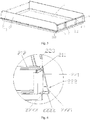
Fig. 1 is a schematic structural diagram of a bottom plate provided according to an embodiment I of the present application; -
Fig. 2 is a schematic structural diagram of end plates and side plates provided according to the embodiment I of the present application before fastening; -
Fig. 3 is a schematic structural diagram of the end plates and the side plates provided according to the embodiment I of the present application during fastening; -
Fig. 4 is a schematic structural diagram of the end plates and the side plates provided according to the embodiment I of the present application after fastening; -
Fig. 5 is a schematic structural diagram of a battery case with a plurality of supports provided according to the embodiment I of the present application; -
Fig. 6 is an enlarged view of the portion A inFig. 3 ; -
Fig. 7 is an enlarged view of the portion B inFig. 4 ; and -
Fig. 8 is a schematic structural diagram of the battery case with battery cells assembled therein provided according to an embodiment III of the present application. -
- 1 - Bottom plate;
- a - Extension;
- 2 - case side arm;
- 21 - End plate;
- 211 - First connecting portion;
- 212 - Reinforcing arm;
- 2121 - First connecting hole;
- 2122 - Reinforcing portion;
- 22 - Side plate;
- 221 - Second connecting portion;
- 222 - Bended arm;
- 2221 - Second connecting hole;
- 2222 - Bended portion;
- 223 - Pressing member;
- 21 - End plate;
- 3 - Support.
- The technical solution of the present utlity model will be clearly and completely described with reference to the drawings. Obviously, the described embodiments are some of, rather than all of, the embodiments of the present utlity model. All the other embodiments obtained by those of ordinary skill in the art based on the embodiments of the present utlity model without any inventive efforts shall fall within the scope of protection of the present utlity model.
- It should be noted that the terms that indicate orientation or positional relationships, such as "inner" and "outer", are based on the orientation or position relationships shown in the figures and are intended to facilitate the description of the present utlity model and simplify the description only, rather than indicating or implying that an apparatus or element referred to must have a particular orientation or be constructed and operated in a particular orientation, and hence will not to be understood to limit the present utlity model.
- In the description of the present utlity model, it should be noted that unless otherwise explicitly specified and defined, the terms "mounting", "connecting" and "connection" should be understood in a broad sense, for example, they may be a fixed connection, a detachable connection, or an integrated connection; may be a mechanical connection or be an electrical connection; may be a direct connection or an indirect connection via an intermediate medium, or may be communication between the interiors of two elements. For those of ordinary skill in the art, the specific meaning of the above terms in the present utlity model may be understood according to specific circumstances.
- Specifically, a battery module includes a battery case and a plurality of battery cells located in the battery case. As shown in
Figs. 2 ,3 and 4 , in this embodiment, the battery case includes abottom plate 1 and a plurality of circumferentially spaced extensions a, and the extensions a are formed by extending horizontally outward along thebottom plate 1, specifically, each extensions a is bended at least once to form a case side arm 2, and a cavity of the battery case are enclosed by the case side arms 2 and thebottom plate 1. Further, end faces for connection of the case side arms 2 are bended to form connecting portions, and two adjacent connecting portions are snap-fitted to fix the adjacent case side arms 2 to each other. As the end faces for connection of the case side arms 2 are bended to form the connecting portions and the two adjacent connecting portions can be snap-fitted when the junctions between the case side arms 2 are fixed, the adjacent case side arms 2 can be fixed to each other only by engaging the adjacent connecting portions of the case side arms 2, such that it is easy to operate and no welding is needed, which simplifies the production process and improves the work efficiency. Further, as the case side arms 2 each are formed by bending each of the extensions a, and the extension a is formed by extending horizontally outward along thebottom plate 1, that is, the case side arms 2 are formed integrally with thebottom plate 1, the structural strength of the whole battery case is increased. - The material from which the battery case is made may be an aluminum material, a steel material or the like, In order to further increase the overall strength of the battery case and ensure that the battery case has good ductility, the material from which the battery case is preferably a steel material in this embodiment.
- As shown in
Fig. 1 , the connecting portions include first connectingportions 211 and a second connectingportions 221, in particular, the case side arms 2 includes at least twoend plates 21 and at least twoside plates 22, and anend plate 21 is arranged between twoadjacent side plates 22. In this embodiment, in order to ensure that the extensions a can be bended to form a closed case side arm 2, three, four, five, six or more extensions a may be provided, and for ease of processing and placement of the battery cells, four extensions a are preferred, thebottom plate 1 is preferably a rectangular plate. Further, four side end faces of thebottom plate 1 extend to form four extensions a. - As shown in
Figs. 2 and3 , specifically, in this embodiment, when the battery case is processed, three of the extensions a can be first bended by 90 degrees along the same bending path, the remaining extension a can be pre-bended by 45 degrees, such that theend plates 21 and theside plates 22 are formed by bending, a plurality of battery cells for making up the battery module are then placed into the enclosed case cavity, and then the pre-bended extension a is bended to a position where theside plates 22 or theend plates 21 adjacent to the extensions provide an enclosure, i.e., being bend by further 45 degrees. - As shown in
Figs. 3 and6 , further, in this embodiment, the end faces for connection of theend plates 21 are bended to form the first connectingportions 211, the end faces for connection of theside plates 22 are bended to form the second connectingportions 221, and the adjacent first connectingportion 211 and second connectingportion 221 are snap-fitted together. In the designed structure, theend plates 21 and theside plates 22 adjacent to each other are fixed by engaging the first connectingportions 211 with the second connectingportions 221, such that it is easy to operate and welding is eliminated. - As shown in
Fig. 6 , in order to engage the first connectingportions 211 with the second connectingportions 221, theend plates 21 and theside plates 22 are both bended along the same path each time. When the first connectingportions 211 are snap-fitted and fitted with the second connectingportions 221, one of the first connectingportions 211 and the second connectingportions 221 that is located on the outer side are fastened to one of the first connecting portions and the second connecting portions that is located on the inner side for engagement by form-fitting. - As shown in
Figs. 2 ,3 ,4 and5 , further, the first connectingportions 211 and the second connectingportions 221 may be located inside the cavity of the battery case. In this embodiment, in order to increase the energy density and prevent the first connectingportions 211 and the second connectingportions 221 from occupying the space in the battery case, it is preferable for both the first connectingportions 211 and the second connectingportions 221 to be located outside the cavity of the battery case. - It should be additionally explained herein that
Fig. 2 shows a state in which the first connectingportions 211 and the second connectingportions 221 are not bended yet. In the state illustrated, the first connectingportions 211 and the second connectingportions 221 may be directly folded over one another, or a structure in which the first connectingportions 211 and the second connectingportions 221 can be fastened together as shown inFig. 3 may also be obtained by bending. - As shown in
Figs. 2 ,3 ,4 and5 , in this embodiment, in order to further increase the structural strength of theend plates 21 and thus the overall structural strength of the battery case, theend plates 21 are bended to form at least one reinforcingarm 212. The reinforcingarms 212 may be arranged in the length direction (Y-axis) of theend plates 21 or in the height direction (Z-axis) of theend plates 21. In order to increase the structural strength of theend plates 21 and further reduce or even avoid the deformation of theend plates 21 caused by the expansion of the battery cells, it is preferable for the reinforcingarms 212 to be arranged parallel to thebottom plate 1. - Further, In addition to that the reinforcing
arms 212 are capable of increasing the structural strength of theend plates 21, connecting members may pass through the reinforcingarms 212 and are connected to the case of the battery pack to fix the battery case to the case of the battery pack, providing connection fixing points for the battery case. - Continuing referring to
Figs. 2 ,3 ,4 and5 , the reinforcingarms 212 may be located outside the cavity structure of the battery case or may be located inside the cavity structure of the battery case. In this embodiment, in order to increase the energy density and prevent the reinforcingarms 212 from occupying the space in the battery case, it is preferable for the reinforcingarms 212 to be located outside the cavity of the battery case. - In the figures, one, two, three, four or more reinforcing
arms 212 may be provided. In this embodiment, in order to be able to reduced or even prevent the deformation of theend plates 21 caused by the expansion of the battery cells and also to simplify the processing procedures, two reinforcingarms 212 are preferably provided, and the two reinforcingarms 212 are located on the top and bottom of theend plate 21. - Further, the top and bottom of the
end plate 21 may be finished several times to form the reinforcingarms 212. In this embodiment, in order to simplify the processing procedures and also to be able to increase the structural strength of theend plate 21, the top and bottom of theend plate 21 are respectively bended twice to form the reinforcingarms 212. - As shown in
Figs. 4 and5 , when the case is fixed, the connecting members need to pass through the reinforcingarms 212 and then are connected to the case of the battery pack. During this process, the connecting members can generate a preload force in the height direction (Z-axis) of the battery case. In order to avoid the deformation of the reinforcingarms 212 caused by the preload force and thus the impact on the structural strength of theend plates 21 as well as on the stability of the connection between theend plates 21 and theside plates 22, in this embodiment, adjacent first connectingportion 211 and second connectingportion 221 are snap-fitted to form at least onesupport 3. Thesupport 3 abuts between two reinforcingarms 212, that is, both the upper and lower end faces of thesupport 3 are in contact with the two upper and lower reinforcingarms 212, such that thesupport 3 can provide a force in a direction opposite to the preload force to reduce or even prevent the deformation of the reinforcingarms 212. - Continuing to refer to
Figs. 4 and5 , it should be noted herein that thesupports 3 at both ends of theend plate 21 are formed after the first connectingportions 211 and the second connectingportions 221 are snap-fitted, and thesupports 3 located at other positions on theend plate 21 may be formed by bending theend plate 21 itself or by engaging the first connectingportions 211 with the second connectingportions 221. - As shown in
Figs. 6 and7 , theend plate 21 may be bended one or more times to form the reinforcingarms 212. In order to further increase the deformation resistance of the reinforcingarms 212, improve the firmness of the connection of the battery case to the case of the battery pack, and to reduce the processing procedures, in this embodiment, theend plate 21 is bended twice to form the reinforcingarms 212. Specifically, the reinforcingarms 212 each include two reinforcingportions 2122 arranged opposite one another. The two reinforcingportions 2122 are each provided with a plurality of second connectingholes 2221 corresponding to one another, and the reinforcingportions 2122 are connected to the case of the battery pack by the connecting members passing through the second connectingholes 2221. - Further, in this embodiment, in order to improve the firmness of the connection of the battery case to the case of the battery pack, the
side plate 22 is bended to form at least onebended arm 222, and thebended arm 222 is arranged parallel to thebottom plate 1. Specifically, thebended arm 222 is provided with the second connectingholes 2221, and thebended arm 222 is connected to the case of the battery pack by the connecting members passing through the second connectingholes 2221. - The
bended arm 222 may be located inside the cavity of the battery case. In order to increase the energy density and prevent thebended arm 222 from occupying the space in the battery case, thebended arm 222 is located outside the cavity of the battery case. Further, As shown inFigs. 2 ,3 ,4 and5 , in this embodiment, the arrangement of both thebended arm 222 and the reinforcingarms 212 outside the cavity of the battery case can also avoid passage of the connecting members through thebottom plate 1 when the batter case is connected to the case of the battery pack, which in turn ensures the integrity of the battery case and increases the overall structural strength. - As shown in
Figs. 6 and7 , theside plate 22 may be bended one or more times to form thebended arms 222. In order to improve the firmness of the connection of the battery case to the case of the battery pack and to reduce the processing procedures, in this embodiment, theside plate 22 is bended twice to form thebended arms 222. Specifically, thebended arms 222 each include two reinforcingportions 2222 arranged opposite one another, and the twobended portions 2222 are each provided with a plurality of the second connectingholes 2221 corresponding to one another. - The top of the
side plate 22 may be not bended. In order to improve the stability of the battery cells in the battery case, in this embodiment, the end face, facing away from thebottom plate 1, of theside plate 22 extends outward to form pressingmembers 223, thepressing members 223 are located inside the cavity of the battery case, and the battery cells are clamped between thepressing members 223 and thebottom plate 1. - This embodiment further provides another structure of a battery case. The battery case includes a
bottom plate 1 and a plurality of the circumferentially spaced extensions a, and the plurality of extensions a are formed by extending horizontally outward along thebottom plate 1, particularly each extension a is bended at least once to form a case side arm 2, and a cavity of the battery case are enclosed by the case side arms 2 and thebottom plate 1. Further, end faces for connection of the case side arms 2 are provided with connecting portions, and the two adjacent connecting portions are folded over one another to fix the adjacent case side arms 2 to each other. - The structure of the battery case provided in this embodiment has the same advantages as the battery case described in the embodiment I, which have been explicitly described above, and will not be described in detail herein again.
- As shown in
Fig. 8 , a battery module is provided in this embodiment and includes a plurality of battery cells stacked together and a battery case in the embodiment I and the embodiment II described above, and the plurality of battery cells stacked together are accommodated inside a cavity of the battery case and clamped between thepressing members 223 and thebottom plate 1. - The battery module has the same advantages as the battery case described in the embodiment I and the embodiment II described above, which have been explicitly described above, and will not be described in detail herein again.
- Finally, it should be noted that the above embodiments are merely used for illustrating rather than limiting the technical solutions of the present utility model; although the present utility model is illustrated in detail with reference to the foregoing embodiments, those of ordinary skill in the art should understand that modifications may still be made to the technical solutions recorded in the foregoing embodiments or equivalent replacements on some or all of the technical features thereof may be made; and these modifications or replacements will not make the essential of corresponding technical solutions depart from the scope of the technical solutions in various embodiments of the present utility model.
Claims (10)
- A battery case, characterized in that, comprising:a bottom plate (1); anda plurality of extensions (a) circumferentially spaced, the extensions (a) being formed by extending horizontally outward along the bottom plate (1), whereineach of the extensions (a) is bended at least once to form a case side arm (2) and a cavity of the battery case is enclosed by the case side arms (2) and the bottom plate (1), andwherein end faces for connection of the case side arms (2) are bended to form connecting portions, and two adjacent connecting portions are snap-fitted to fix the adjacent case side arms (2) to each other.
- The battery case according to claim 1, characterized in that, the connecting portions comprise first connecting portions (211) and second connecting portions (221);
the case side arms (2) comprise:at least two end plates (21), end faces for connection of the end plates (21) being bended to form the first connecting portions (211); andat least two side plates (22), an end plate (21) being arranged between the adjacent side plates (22), end faces for connection of the side plates (22) being bended to form the second connecting portions (221); andadjacent first connecting portion (211) and second connecting portion (221) are snap-fitted together. - The battery case according to claim 2, characterized in that, the end plates (21) are bended to form at least one reinforcing arm (212), and the reinforcing arm (212) is arranged parallel to the bottom plate (1); and
the reinforcing arm (212) is located outside the cavity of the battery case. - The battery case according to claim 3, characterized in that, the number of the reinforcing arms (212) is two, the adjacent first connecting portion (211) and second connecting portion (221) are snap-fitted to form at least one support (3), and the support (3) abuts between two reinforcing arms (212).
- The battery case according to claim 3, characterized in that, the reinforcing arm (212) comprises two reinforcing portions (2122) arranged opposite one another, and the two reinforcing portions (2122) are both provided with a plurality of first connecting holes (2121) corresponding to one another; and
the reinforcing arm (212) is connected to a case of a battery pack by a connecting member passing through the first connecting holes (2121). - The battery case according to claim 2, characterized in that, the side plates (22) are bended to form at least one bended arm (222), the bended arm (222) is arranged parallel to the bottom plate (1), and the bended arm (222) is located outside the cavity of the battery case; and
the bended arm (222) is provided with a second connecting hole (2221), and the bended arm (222) is connected to a case of a battery pack by a connecting member passing through the second connecting hole (2221). - The battery case according to claim 6, characterized in that, the bended arm (222) comprises:
two bended portions (2222) arranged opposite one another, the two bended portions (2222) being both provided with a plurality of second connecting holes (2221) corresponding to one another. - The battery case according to claim 2, characterized in that, the end faces, facing away from the bottom plate (1), of the side plates (22) extend outward to form pressing members (223), and the pressing members (223) are located inside the cavity of the battery case.
- A battery case, characterized in that, comprising:a bottom plate (1); anda plurality of extensions (a) circumferentially spaced formed by extending horizontally outward along the bottom plate (1), whereineach of the extensions (a) is bended at least once to form a case side arm (2) and a cavity of the battery case is enclosed by the case side arms (2) and the bottom plate (1), andend faces for connection of the case side arms (2) are provided with connecting portions, and two adjacent connecting portions are folded over one another to fix the adjacent case side arms (2) to each other.
- A battery module, characterized in that, comprising: a plurality of battery cells stacked together and a battery case in any one of claims 1 to 9; wherein
the plurality of battery cells stacked together are accommodated inside the cavity of the battery case and are clamped between the pressing members (223) and the bottom plate (1).
Applications Claiming Priority (2)
| Application Number | Priority Date | Filing Date | Title |
|---|---|---|---|
| CN201822254181.7U CN209045658U (en) | 2018-12-29 | 2018-12-29 | Battery case and battery modules |
| PCT/CN2019/075821 WO2020133657A1 (en) | 2018-12-29 | 2019-02-22 | Battery box and battery module |
Publications (3)
| Publication Number | Publication Date |
|---|---|
| EP3800695A1 true EP3800695A1 (en) | 2021-04-07 |
| EP3800695A4 EP3800695A4 (en) | 2021-10-27 |
| EP3800695B1 EP3800695B1 (en) | 2022-07-06 |
Family
ID=67045066
Family Applications (1)
| Application Number | Title | Priority Date | Filing Date |
|---|---|---|---|
| EP19903656.7A Active EP3800695B1 (en) | 2018-12-29 | 2019-02-22 | Battery box and battery module |
Country Status (4)
| Country | Link |
|---|---|
| US (1) | US11108115B2 (en) |
| EP (1) | EP3800695B1 (en) |
| CN (1) | CN209045658U (en) |
| WO (1) | WO2020133657A1 (en) |
Families Citing this family (12)
| Publication number | Priority date | Publication date | Assignee | Title |
|---|---|---|---|---|
| CN113352866B (en) * | 2020-03-04 | 2024-02-27 | 比亚迪股份有限公司 | Battery tray, battery package and electric automobile |
| US11652254B2 (en) | 2020-09-04 | 2023-05-16 | Beta Air, Llc | System and method for high energy density battery module |
| US20220407162A1 (en) * | 2021-06-21 | 2022-12-22 | Rivian Ip Holdings, Llc | Cell carrier with integrated side walls |
| CN114597468A (en) * | 2022-02-22 | 2022-06-07 | 上海兰钧新能源科技有限公司 | Battery manufacturing method and battery |
| CN114665171B (en) * | 2022-03-24 | 2025-08-05 | 中国华能集团清洁能源技术研究院有限公司 | Battery pack module replacement system and method |
| DE102022108978A1 (en) | 2022-04-12 | 2023-10-12 | Azl Aachen Gmbh | Battery housing and battery for an electrically powered vehicle and method |
| WO2024005394A1 (en) * | 2022-06-27 | 2024-01-04 | 주식회사 엘지에너지솔루션 | Battery pack |
| CN115084732A (en) * | 2022-07-20 | 2022-09-20 | 上海兰钧新能源科技有限公司 | Preparation method of battery shell, battery shell and battery |
| EP4525159A4 (en) * | 2022-12-30 | 2025-08-06 | Contemporary Amperex Technology Hong Kong Ltd | Case body, case assembly, battery and electrical device |
| CN116060142B (en) * | 2023-02-10 | 2024-11-26 | 江苏拓米洛高端装备股份有限公司 | Inner box and environmental test chamber |
| WO2024187320A1 (en) * | 2023-03-10 | 2024-09-19 | 厦门新能达科技有限公司 | Battery pack, electric device and manufacturing method for battery pack |
| CN221352986U (en) * | 2023-10-30 | 2024-07-16 | 惠州亿纬锂能股份有限公司 | Strengthen components and battery modules |
Family Cites Families (9)
| Publication number | Priority date | Publication date | Assignee | Title |
|---|---|---|---|---|
| US3146132A (en) * | 1961-12-07 | 1964-08-25 | Nathan Sanford | Battery climatizer cover |
| NL288152A (en) * | 1962-01-29 | |||
| EP0579759A1 (en) * | 1991-04-11 | 1994-01-26 | Qube Corporation | Foldable electrical component enclosures |
| JP5747597B2 (en) * | 2011-03-24 | 2015-07-15 | 株式会社Gsユアサ | Battery storage case |
| WO2013035668A1 (en) * | 2011-09-09 | 2013-03-14 | 三洋電機株式会社 | Square-shaped sealed secondary battery and method of manufacturing same |
| JP5909816B1 (en) * | 2015-03-20 | 2016-04-27 | 日立化成株式会社 | Battery tray |
| US10637023B2 (en) * | 2017-09-06 | 2020-04-28 | Benteler Automobiltechnik Gmbh | Battery carrier for an electric motor vehicle |
| CN107958972A (en) * | 2017-11-16 | 2018-04-24 | 北京航空航天大学 | The battery shell structure and preparation process of a kind of metal and composite panel Mixed Design |
| CN108183184B (en) * | 2017-12-06 | 2023-11-10 | 力帆实业(集团)股份有限公司 | Battery module installation and fixing structure |
-
2018
- 2018-12-29 CN CN201822254181.7U patent/CN209045658U/en active Active
-
2019
- 2019-02-22 WO PCT/CN2019/075821 patent/WO2020133657A1/en not_active Ceased
- 2019-02-22 EP EP19903656.7A patent/EP3800695B1/en active Active
-
2020
- 2020-12-31 US US17/139,980 patent/US11108115B2/en active Active
Also Published As
| Publication number | Publication date |
|---|---|
| US11108115B2 (en) | 2021-08-31 |
| WO2020133657A1 (en) | 2020-07-02 |
| EP3800695A4 (en) | 2021-10-27 |
| EP3800695B1 (en) | 2022-07-06 |
| US20210126318A1 (en) | 2021-04-29 |
| CN209045658U (en) | 2019-06-28 |
Similar Documents
| Publication | Publication Date | Title |
|---|---|---|
| US11108115B2 (en) | Battery case and battery module | |
| EP3905371A1 (en) | Battery box and battery module | |
| EP2897193B1 (en) | Rechargeable battery pack | |
| US20190006646A1 (en) | Battery pack | |
| EP2843728A2 (en) | Battery pack | |
| EP2919294A1 (en) | Assembled battery and method for manufacturing assembled battery | |
| JPWO2018142809A1 (en) | Power storage device | |
| EP3930090A1 (en) | Sampling component, battery module, battery pack, and device | |
| US9455425B2 (en) | Battery module | |
| EP3506391B1 (en) | Battery module with composite end plate | |
| JP2011119222A (en) | Battery module, and battery pack equipped with two or more battery modules | |
| KR102646201B1 (en) | Wiring harness separator assemblies, battery modules, battery packs and devices | |
| EP3154108A1 (en) | Battery module and battery pack including same | |
| KR20170142481A (en) | Secondary battery module, and secondary battery pack including the same | |
| KR101913375B1 (en) | Battery Module | |
| EP2940757A1 (en) | Battery module and battery pack | |
| US20240387952A1 (en) | Busbar Assembly, Cylindrical Power Battery Module, and Battery Pack | |
| CN219779095U (en) | Battery box, battery and electrical device | |
| EP4365921A1 (en) | Capacitor module and motor inverter | |
| KR102915631B1 (en) | Battery module including busbar frame separated from top and bottom and assembly method having the same | |
| CN223390683U (en) | Battery pack and power utilization device | |
| CN219350522U (en) | Battery module | |
| CN222601223U (en) | Battery Box | |
| CN217427015U (en) | Bus bar and battery system | |
| CN219677432U (en) | Module structure |
Legal Events
| Date | Code | Title | Description |
|---|---|---|---|
| STAA | Information on the status of an ep patent application or granted ep patent |
Free format text: STATUS: THE INTERNATIONAL PUBLICATION HAS BEEN MADE |
|
| PUAI | Public reference made under article 153(3) epc to a published international application that has entered the european phase |
Free format text: ORIGINAL CODE: 0009012 |
|
| STAA | Information on the status of an ep patent application or granted ep patent |
Free format text: STATUS: REQUEST FOR EXAMINATION WAS MADE |
|
| 17P | Request for examination filed |
Effective date: 20201231 |
|
| AK | Designated contracting states |
Kind code of ref document: A1 Designated state(s): AL AT BE BG CH CY CZ DE DK EE ES FI FR GB GR HR HU IE IS IT LI LT LU LV MC MK MT NL NO PL PT RO RS SE SI SK SM TR |
|
| AX | Request for extension of the european patent |
Extension state: BA ME |
|
| REG | Reference to a national code |
Ref country code: DE Ref legal event code: R079 Ref document number: 602019016849 Country of ref document: DE Free format text: PREVIOUS MAIN CLASS: H01M0002100000 Ipc: H01M0050200000 |
|
| A4 | Supplementary search report drawn up and despatched |
Effective date: 20210924 |
|
| RIC1 | Information provided on ipc code assigned before grant |
Ipc: H01M 50/20 20210101AFI20210920BHEP |
|
| GRAP | Despatch of communication of intention to grant a patent |
Free format text: ORIGINAL CODE: EPIDOSNIGR1 |
|
| STAA | Information on the status of an ep patent application or granted ep patent |
Free format text: STATUS: GRANT OF PATENT IS INTENDED |
|
| DAV | Request for validation of the european patent (deleted) | ||
| DAX | Request for extension of the european patent (deleted) | ||
| INTG | Intention to grant announced |
Effective date: 20220321 |
|
| GRAS | Grant fee paid |
Free format text: ORIGINAL CODE: EPIDOSNIGR3 |
|
| GRAA | (expected) grant |
Free format text: ORIGINAL CODE: 0009210 |
|
| STAA | Information on the status of an ep patent application or granted ep patent |
Free format text: STATUS: THE PATENT HAS BEEN GRANTED |
|
| AK | Designated contracting states |
Kind code of ref document: B1 Designated state(s): AL AT BE BG CH CY CZ DE DK EE ES FI FR GB GR HR HU IE IS IT LI LT LU LV MC MK MT NL NO PL PT RO RS SE SI SK SM TR |
|
| REG | Reference to a national code |
Ref country code: AT Ref legal event code: REF Ref document number: 1503526 Country of ref document: AT Kind code of ref document: T Effective date: 20220715 Ref country code: CH Ref legal event code: EP |
|
| REG | Reference to a national code |
Ref country code: DE Ref legal event code: R096 Ref document number: 602019016849 Country of ref document: DE |
|
| REG | Reference to a national code |
Ref country code: IE Ref legal event code: FG4D |
|
| REG | Reference to a national code |
Ref country code: LT Ref legal event code: MG9D |
|
| REG | Reference to a national code |
Ref country code: NL Ref legal event code: MP Effective date: 20220706 |
|
| PG25 | Lapsed in a contracting state [announced via postgrant information from national office to epo] |
Ref country code: SE Free format text: LAPSE BECAUSE OF FAILURE TO SUBMIT A TRANSLATION OF THE DESCRIPTION OR TO PAY THE FEE WITHIN THE PRESCRIBED TIME-LIMIT Effective date: 20220706 Ref country code: RS Free format text: LAPSE BECAUSE OF FAILURE TO SUBMIT A TRANSLATION OF THE DESCRIPTION OR TO PAY THE FEE WITHIN THE PRESCRIBED TIME-LIMIT Effective date: 20220706 Ref country code: PT Free format text: LAPSE BECAUSE OF FAILURE TO SUBMIT A TRANSLATION OF THE DESCRIPTION OR TO PAY THE FEE WITHIN THE PRESCRIBED TIME-LIMIT Effective date: 20221107 Ref country code: NO Free format text: LAPSE BECAUSE OF FAILURE TO SUBMIT A TRANSLATION OF THE DESCRIPTION OR TO PAY THE FEE WITHIN THE PRESCRIBED TIME-LIMIT Effective date: 20221006 Ref country code: NL Free format text: LAPSE BECAUSE OF FAILURE TO SUBMIT A TRANSLATION OF THE DESCRIPTION OR TO PAY THE FEE WITHIN THE PRESCRIBED TIME-LIMIT Effective date: 20220706 Ref country code: LV Free format text: LAPSE BECAUSE OF FAILURE TO SUBMIT A TRANSLATION OF THE DESCRIPTION OR TO PAY THE FEE WITHIN THE PRESCRIBED TIME-LIMIT Effective date: 20220706 Ref country code: LT Free format text: LAPSE BECAUSE OF FAILURE TO SUBMIT A TRANSLATION OF THE DESCRIPTION OR TO PAY THE FEE WITHIN THE PRESCRIBED TIME-LIMIT Effective date: 20220706 Ref country code: FI Free format text: LAPSE BECAUSE OF FAILURE TO SUBMIT A TRANSLATION OF THE DESCRIPTION OR TO PAY THE FEE WITHIN THE PRESCRIBED TIME-LIMIT Effective date: 20220706 Ref country code: ES Free format text: LAPSE BECAUSE OF FAILURE TO SUBMIT A TRANSLATION OF THE DESCRIPTION OR TO PAY THE FEE WITHIN THE PRESCRIBED TIME-LIMIT Effective date: 20220706 |
|
| REG | Reference to a national code |
Ref country code: AT Ref legal event code: MK05 Ref document number: 1503526 Country of ref document: AT Kind code of ref document: T Effective date: 20220706 |
|
| PG25 | Lapsed in a contracting state [announced via postgrant information from national office to epo] |
Ref country code: PL Free format text: LAPSE BECAUSE OF FAILURE TO SUBMIT A TRANSLATION OF THE DESCRIPTION OR TO PAY THE FEE WITHIN THE PRESCRIBED TIME-LIMIT Effective date: 20220706 Ref country code: IS Free format text: LAPSE BECAUSE OF FAILURE TO SUBMIT A TRANSLATION OF THE DESCRIPTION OR TO PAY THE FEE WITHIN THE PRESCRIBED TIME-LIMIT Effective date: 20221106 Ref country code: HR Free format text: LAPSE BECAUSE OF FAILURE TO SUBMIT A TRANSLATION OF THE DESCRIPTION OR TO PAY THE FEE WITHIN THE PRESCRIBED TIME-LIMIT Effective date: 20220706 Ref country code: GR Free format text: LAPSE BECAUSE OF FAILURE TO SUBMIT A TRANSLATION OF THE DESCRIPTION OR TO PAY THE FEE WITHIN THE PRESCRIBED TIME-LIMIT Effective date: 20221007 |
|
| REG | Reference to a national code |
Ref country code: DE Ref legal event code: R097 Ref document number: 602019016849 Country of ref document: DE |
|
| PG25 | Lapsed in a contracting state [announced via postgrant information from national office to epo] |
Ref country code: SM Free format text: LAPSE BECAUSE OF FAILURE TO SUBMIT A TRANSLATION OF THE DESCRIPTION OR TO PAY THE FEE WITHIN THE PRESCRIBED TIME-LIMIT Effective date: 20220706 Ref country code: RO Free format text: LAPSE BECAUSE OF FAILURE TO SUBMIT A TRANSLATION OF THE DESCRIPTION OR TO PAY THE FEE WITHIN THE PRESCRIBED TIME-LIMIT Effective date: 20220706 Ref country code: DK Free format text: LAPSE BECAUSE OF FAILURE TO SUBMIT A TRANSLATION OF THE DESCRIPTION OR TO PAY THE FEE WITHIN THE PRESCRIBED TIME-LIMIT Effective date: 20220706 Ref country code: CZ Free format text: LAPSE BECAUSE OF FAILURE TO SUBMIT A TRANSLATION OF THE DESCRIPTION OR TO PAY THE FEE WITHIN THE PRESCRIBED TIME-LIMIT Effective date: 20220706 Ref country code: AT Free format text: LAPSE BECAUSE OF FAILURE TO SUBMIT A TRANSLATION OF THE DESCRIPTION OR TO PAY THE FEE WITHIN THE PRESCRIBED TIME-LIMIT Effective date: 20220706 |
|
| PLBE | No opposition filed within time limit |
Free format text: ORIGINAL CODE: 0009261 |
|
| STAA | Information on the status of an ep patent application or granted ep patent |
Free format text: STATUS: NO OPPOSITION FILED WITHIN TIME LIMIT |
|
| PG25 | Lapsed in a contracting state [announced via postgrant information from national office to epo] |
Ref country code: SK Free format text: LAPSE BECAUSE OF FAILURE TO SUBMIT A TRANSLATION OF THE DESCRIPTION OR TO PAY THE FEE WITHIN THE PRESCRIBED TIME-LIMIT Effective date: 20220706 Ref country code: EE Free format text: LAPSE BECAUSE OF FAILURE TO SUBMIT A TRANSLATION OF THE DESCRIPTION OR TO PAY THE FEE WITHIN THE PRESCRIBED TIME-LIMIT Effective date: 20220706 |
|
| 26N | No opposition filed |
Effective date: 20230411 |
|
| P01 | Opt-out of the competence of the unified patent court (upc) registered |
Effective date: 20230516 |
|
| PG25 | Lapsed in a contracting state [announced via postgrant information from national office to epo] |
Ref country code: AL Free format text: LAPSE BECAUSE OF FAILURE TO SUBMIT A TRANSLATION OF THE DESCRIPTION OR TO PAY THE FEE WITHIN THE PRESCRIBED TIME-LIMIT Effective date: 20220706 |
|
| PG25 | Lapsed in a contracting state [announced via postgrant information from national office to epo] |
Ref country code: SI Free format text: LAPSE BECAUSE OF FAILURE TO SUBMIT A TRANSLATION OF THE DESCRIPTION OR TO PAY THE FEE WITHIN THE PRESCRIBED TIME-LIMIT Effective date: 20220706 |
|
| PG25 | Lapsed in a contracting state [announced via postgrant information from national office to epo] |
Ref country code: MC Free format text: LAPSE BECAUSE OF FAILURE TO SUBMIT A TRANSLATION OF THE DESCRIPTION OR TO PAY THE FEE WITHIN THE PRESCRIBED TIME-LIMIT Effective date: 20220706 |
|
| REG | Reference to a national code |
Ref country code: CH Ref legal event code: PL |
|
| REG | Reference to a national code |
Ref country code: BE Ref legal event code: MM Effective date: 20230228 |
|
| PG25 | Lapsed in a contracting state [announced via postgrant information from national office to epo] |
Ref country code: LU Free format text: LAPSE BECAUSE OF NON-PAYMENT OF DUE FEES Effective date: 20230222 Ref country code: LI Free format text: LAPSE BECAUSE OF NON-PAYMENT OF DUE FEES Effective date: 20230228 Ref country code: CH Free format text: LAPSE BECAUSE OF NON-PAYMENT OF DUE FEES Effective date: 20230228 |
|
| REG | Reference to a national code |
Ref country code: IE Ref legal event code: MM4A |
|
| PG25 | Lapsed in a contracting state [announced via postgrant information from national office to epo] |
Ref country code: IE Free format text: LAPSE BECAUSE OF NON-PAYMENT OF DUE FEES Effective date: 20230222 |
|
| PG25 | Lapsed in a contracting state [announced via postgrant information from national office to epo] |
Ref country code: BE Free format text: LAPSE BECAUSE OF NON-PAYMENT OF DUE FEES Effective date: 20230228 |
|
| REG | Reference to a national code |
Ref country code: DE Ref legal event code: R081 Ref document number: 602019016849 Country of ref document: DE Owner name: CONTEMPORARY AMPEREX TECHNOLOGY (HONG KONG) LI, HK Free format text: FORMER OWNER: CONTEMPORARY AMPEREX TECHNOLOGY CO., LTD., NINGDE, FUJIAN, CN |
|
| REG | Reference to a national code |
Ref country code: GB Ref legal event code: 732E Free format text: REGISTERED BETWEEN 20240822 AND 20240828 |
|
| PG25 | Lapsed in a contracting state [announced via postgrant information from national office to epo] |
Ref country code: BG Free format text: LAPSE BECAUSE OF FAILURE TO SUBMIT A TRANSLATION OF THE DESCRIPTION OR TO PAY THE FEE WITHIN THE PRESCRIBED TIME-LIMIT Effective date: 20220706 |
|
| PG25 | Lapsed in a contracting state [announced via postgrant information from national office to epo] |
Ref country code: BG Free format text: LAPSE BECAUSE OF FAILURE TO SUBMIT A TRANSLATION OF THE DESCRIPTION OR TO PAY THE FEE WITHIN THE PRESCRIBED TIME-LIMIT Effective date: 20220706 |
|
| PG25 | Lapsed in a contracting state [announced via postgrant information from national office to epo] |
Ref country code: CY Free format text: LAPSE BECAUSE OF FAILURE TO SUBMIT A TRANSLATION OF THE DESCRIPTION OR TO PAY THE FEE WITHIN THE PRESCRIBED TIME-LIMIT; INVALID AB INITIO Effective date: 20190222 |
|
| PG25 | Lapsed in a contracting state [announced via postgrant information from national office to epo] |
Ref country code: HU Free format text: LAPSE BECAUSE OF FAILURE TO SUBMIT A TRANSLATION OF THE DESCRIPTION OR TO PAY THE FEE WITHIN THE PRESCRIBED TIME-LIMIT; INVALID AB INITIO Effective date: 20190222 |
|
| PG25 | Lapsed in a contracting state [announced via postgrant information from national office to epo] |
Ref country code: TR Free format text: LAPSE BECAUSE OF FAILURE TO SUBMIT A TRANSLATION OF THE DESCRIPTION OR TO PAY THE FEE WITHIN THE PRESCRIBED TIME-LIMIT Effective date: 20220706 |
|
| PGFP | Annual fee paid to national office [announced via postgrant information from national office to epo] |
Ref country code: FR Payment date: 20251231 Year of fee payment: 8 |
|
| PGFP | Annual fee paid to national office [announced via postgrant information from national office to epo] |
Ref country code: GB Payment date: 20260106 Year of fee payment: 8 |
|
| PGFP | Annual fee paid to national office [announced via postgrant information from national office to epo] |
Ref country code: DE Payment date: 20251230 Year of fee payment: 8 |
|
| PGFP | Annual fee paid to national office [announced via postgrant information from national office to epo] |
Ref country code: IT Payment date: 20260122 Year of fee payment: 8 |
|
| PG25 | Lapsed in a contracting state [announced via postgrant information from national office to epo] |
Ref country code: MT Free format text: LAPSE BECAUSE OF NON-PAYMENT OF DUE FEES Effective date: 20230222 |