EP3800687A1 - Battery module - Google Patents
Battery module Download PDFInfo
- Publication number
- EP3800687A1 EP3800687A1 EP19926733.7A EP19926733A EP3800687A1 EP 3800687 A1 EP3800687 A1 EP 3800687A1 EP 19926733 A EP19926733 A EP 19926733A EP 3800687 A1 EP3800687 A1 EP 3800687A1
- Authority
- EP
- European Patent Office
- Prior art keywords
- cell
- battery module
- shape
- glue
- cell separator
- Prior art date
- Legal status (The legal status is an assumption and is not a legal conclusion. Google has not performed a legal analysis and makes no representation as to the accuracy of the status listed.)
- Pending
Links
Images





Classifications
-
- H—ELECTRICITY
- H01—ELECTRIC ELEMENTS
- H01M—PROCESSES OR MEANS, e.g. BATTERIES, FOR THE DIRECT CONVERSION OF CHEMICAL ENERGY INTO ELECTRICAL ENERGY
- H01M50/00—Constructional details or processes of manufacture of the non-active parts of electrochemical cells other than fuel cells, e.g. hybrid cells
- H01M50/20—Mountings; Secondary casings or frames; Racks, modules or packs; Suspension devices; Shock absorbers; Transport or carrying devices; Holders
- H01M50/202—Casings or frames around the primary casing of a single cell or a single battery
-
- H—ELECTRICITY
- H01—ELECTRIC ELEMENTS
- H01M—PROCESSES OR MEANS, e.g. BATTERIES, FOR THE DIRECT CONVERSION OF CHEMICAL ENERGY INTO ELECTRICAL ENERGY
- H01M50/00—Constructional details or processes of manufacture of the non-active parts of electrochemical cells other than fuel cells, e.g. hybrid cells
- H01M50/20—Mountings; Secondary casings or frames; Racks, modules or packs; Suspension devices; Shock absorbers; Transport or carrying devices; Holders
- H01M50/204—Racks, modules or packs for multiple batteries or multiple cells
- H01M50/207—Racks, modules or packs for multiple batteries or multiple cells characterised by their shape
- H01M50/209—Racks, modules or packs for multiple batteries or multiple cells characterised by their shape adapted for prismatic or rectangular cells
-
- H—ELECTRICITY
- H01—ELECTRIC ELEMENTS
- H01M—PROCESSES OR MEANS, e.g. BATTERIES, FOR THE DIRECT CONVERSION OF CHEMICAL ENERGY INTO ELECTRICAL ENERGY
- H01M2220/00—Batteries for particular applications
- H01M2220/20—Batteries in motive systems, e.g. vehicle, ship, plane
Definitions
- the present invention relates to the field of energy storage technologies, and more particularly, to a battery module.
- Battery modules are the "heart" of electric vehicles.
- the battery modules are the core portion for providing the power source for the new energy transportation vehicles, such as pure electrics vehicle and hybrid vehicle.
- the battery modules play main roles of protecting the cell and outputting the power source, and the structure design of the battery module is a key link to ensure the safety of the cell.
- a loop-shaped rubber ring is generally arranged between the cells in the prior art, and a length of the module is controlled by using a compressibility of the loop-shaped rubber ring through applying a clamping force to end plates at two ends.
- a compression amount of each loop-shaped rubber ring in the module is uncontrollable, which is restricted by a current level of an existing cell manufacturing industry, the cell has a large thickness tolerance on different positions during manufacturing, and the tolerance is absorbed by using the compressibility of the loop-shaped rubber ring, but a pressure and a compression amount of the loop-shaped rubber ring during grouping of the module are uncontrollable, resulting in a poor length accuracy of the module after grouping.
- a performance of the loop-shaped rubber ring is greatly changed at high and low temperatures, and the loop-shaped rubber ring may be softened at a high temperature, which is likely to cause contact between the cells, resulting in an adverse consequence.
- the present invention provides a battery module, which addresses the problem of large thickness tolerances of cells and cell separators.
- the embodiment of the present invention provides a battery module, which comprises a cell, a cell separator and UV glue, wherein the cell and the cell separator are fixed through the UV glue to form a separate small component, and a plurality of the small components are stacked along a thickness direction of the cells to form a cell body of the battery module.
- a shape of the cell separator comprises an I-shape, a hollow-square shape, a regular U-shape, an inverted U-shape, a two-vertical-strip shape, a two-horizontal-strip shape and a four-point shape.
- the cell separator is made of plastic capable of transmitting ultraviolet light.
- a body of the cell separator is provided with a first surface and a second surface, and the first surface of the body of the cell separator is provided with a UV glue coating area and a glue overflow groove.
- the UV glue coating area is arranged on the first surface according to the following manners or combinations of a four-corner manner, a loop manner, a two-horizontal-strip manner, a two-vertical-strip manner, a regular U-shape manner and an inverted U-shape manner.
- the glue overflow groove is configured to surround the UV glue coating area.
- the second surface of the body of the cell separator is provide with a reference plane boss.
- UV glue coating area corresponds to the reference plane boss.
- a shape of the reference plane boss is a rectangle, a C-shape, a W-shape, an O-shape, a Y-shape, a circle or a triangle.
- edges of the cell separators in adjacent small components are not contacted with each other.
- the cell separators in adjacent small components are reserved with cell expansion areas on central positions of the cells.
- an adhesion thickness of the UV glue is adjustable.
- a manufacturing tolerance of the cell and the cell separator may be controlled and absorbed by controlling the adhesion thickness of the UV glue, thereby solving the problem of the large thickness tolerance of the cell and the cell separator; and the cell separators in adjacent small components are reserved with cell expansion spaces on the central positions of the cells, thereby reserving a space for expansion of the cell and ensuring the safety of the module.
- the second surface of the body of the cell separator is provide with the reference plane boss to realize rapid positioning during stacking of the small components, thereby improving the production efficiency and the manufacturing accuracy, and in addition, the edges of the cell separators in adjacent small components are not contacted with each other, so that the force is not transmitted, thereby preventing the cell separator from being deformed to affect the safety of the module.
- 1 refers to wire harness
- 2 refers to upper cover
- 3 refers to connecting sheet
- 4 refers to electrical separator
- 5 refers to side plate
- 6 refers to cell separator
- 61 refers to side opening
- 62 refers to UV glue coating area
- 63 refers to glue overflow groove
- 64 refers to reference plane boss
- 65 refers to expansion area
- 66 refers to first surface
- 67 refers to second surface
- 68 refers to first separator
- 69 refers to second separator
- 681 refers to cell separator of the first embodiment
- 682 refers to cell separator of the second embodiment
- 683 refers to cell separator of the third embodiment
- 685 refers to cell separator of the fourth embodiment
- 687 refers to cell separator of the fifth embodiment
- 7 refers to UV glue
- 8 refers to cell
- 81 refers to cell pole
- 9 refers to end plate.
- the embodiment of the present invention provides a battery module, which comprises a cell (8), a cell separator (6) and UV glue (7), wherein the cell (8) and the cell separator (6) are fixed through the UV glue (7) to form a separate small component, and a plurality of the small components are stacked along a thickness direction of the cells to form a cell body of the battery module.
- a shape of the cell separator (6) comprises an I-shape, a hollow-square shape, a regular U-shape, an inverted U-shape, a two-vertical-strip shape, a two-horizontal-strip shape and a four-point shape.
- the cell separator (6) is made of plastic capable of transmitting ultraviolet light.
- a body of the cell separator (6) is provided with a first surface (66) and a second surface (67), and the first surface (66) of the body of the cell separator (6) is provided with a UV glue coating area (62) and a glue overflow groove (63).
- the UV glue coating area (63) is arranged on the first surface (66) according to the following manners or combinations of a four-corner manner, a loop manner, a two-horizontal-strip manner, a two-vertical-strip manner, a regular U-shape manner and an inverted U-shape manner.
- the glue overflow groove (63) surrounds the UV glue coating area (62).
- the second surface (67) of the body of the cell separator (6) is provide with a reference plane boss (64).
- UV glue coating area (62) corresponds to the reference plane boss (64).
- a shape of the reference plane boss (64) is a rectangle, a C-shape, a W-shape, an O-shape, a Y-shape, a circle or a triangle.
- edges of the cell separators (6) in adjacent small components are not contacted with each other.
- cell separators (6) in adjacent small components are reserved with cell expansion areas (65) on central positions of the cells.
- an adhesion thickness of the UV glue (7) is adjustable.
- the battery module is composed of a cell separator (681) of the first embodiment, and as shown in FIG. 2 to FIG. 4 , the cell separator (681) of the first embodiment is made of a PC material and is in a rectangle.
- An oval side opening (61) is arranged at a center of a side edge of the cell separator (6), the body of the cell separator (6) is completely hollowed out on a position corresponding to the side opening (61) to form the expansion area (65), and the side plate (5) of the battery module is provided with a vent on the position corresponding to the side opening (61) of the cell separator.
- cooling gas may pass through the battery module through the vent on the side plate (5) of the battery module and is directly contacted with the cell (7) to cool the cell (7).
- the expansion area (65) traverses the cell separator (6), and a width of the expansion area is the same as a height of the side opening (61), thereby reserving a space for expansion of the cell (7).
- UV glue coating areas (63) and four glue overflow grooves (62) are respectively arranged on four vertex positions on one side of the cell separator (6), the UV glue coating areas (63) are in a rectangle, and the other side of the cell separator (6) is provided with the reference plane bosses (64) on positions corresponding to the UV glue coating areas (63).
- the glue overflow grooves (62) may accommodate redundant UV glue to prevent overflow of the UV glue from affecting new energy of the battery module, and the reference plane boss (64) may further extrude a contact portion between the cell (7) and the UV glue, thus improving an adhesion stability between the cell (7) and the cell separator (6).
- Positioning devices (66) are respectively arranged at two ends of a top of the cell separator (6), which are able to provide positioning assistance for two adjacent cell separators (6) when the battery module is assembled.
- the top of the cell separator (6) is provided with an exhaust channel mounting and fixing site (67) on a position corresponding to an explosion-proof valve of the cell (7). After all the cells (7) and the cell separators (6) are assembled, an exhaust channel is assembled in the exhaust channel mounting and fixing site (67), and gas ejected from the explosion-proof valve of the cell (7) is collected to prevent an electrolyte from splashing around, thus further improving the safety of the whole battery module.
- the battery module is composed of a cell separator (682) of the second embodiment.
- the cell separator (682) of the second embodiment may be replaced by a cell separator (683) of the third embodiment, a cell separator (685) of the fourth embodiment or a fifth cell separator (687) according to a condition, and the cell separator of each embodiment will be further described hereinafter.
- the cell separator (682) of the second embodiment has a rectangular frame structure as a whole, and a center of the cell separator (6) is the expansion area, thus reserving a space for expansion of the cell (7).
- the cell (7) When the cell (7) is heated and expanded during operation, the cell (7) will be deformed along the thickness direction of the cells, and the expansion area (65) is able to reserve an enough space for the deformation, thus reducing an effect of the deformation of the cell (7) on the whole battery module.
- Two UV glue coating areas (63) and two glue overflow grooves (62) are respectively arranged on two wide edge positions of the cell separator (6), the UV glue coating areas (63) are in a rectangle, and the other side of the cell separator (6) is provided with the reference plane bosses (64) on positions corresponding to the UV glue coating areas (63).
- the glue overflow grooves (62) may accommodate redundant UV glue to prevent overflow of the UV glue from affecting new energy of the battery module, and the reference plane boss (64) may further extrude a contact portion between the cell (7) and the UV glue, thus improving an adhesion stability between the cell (7) and the cell separator (6).
- the cell separator (683) of the third embodiment has a U-shaped frame structure as a whole, and an opening position of the cell separator (6) is the expansion area, thereby reserving a space for expansion of the cell (7).
- the cell (7) When the cell (7) is heated and expanded during operation, the cell (7) will be deformed along the thickness direction of the cells, and the expansion area (65) is able to reserve an enough space for the deformation, thereby reducing an effect of the deformation of the cell (7) on the whole battery module.
- Two UV glue coating areas (63) and two glue overflow grooves (62) are respectively arranged on two side edge positions of the cell separator (6), the UV glue coating areas (63) are in a rectangle, and the other side of the cell separator (6) is provided with the reference plane bosses (64) on positions corresponding to the UV glue coating areas (63).
- the glue overflow grooves (62) may accommodate redundant UV glue to prevent overflow of the UV glue from affecting new energy of the battery module, and the reference plane boss (64) may further extrude a contact portion between the cell (7) and the UV glue, thereby improving an adhesion stability between the cell (7) and the cell separator (6).
- the cell separator (6) shown in FIG. 7 is a U-shaped frame with an upward opening
- the cell separator (6) shown in FIG. 8 is a U-shaped frame with a downward opening.
- the two U-shaped frames have the same structure but different opening directions, and similarly, the U-shaped frame may also have a left or right opening.
- the cell separator (685) of the fourth embodiment is composed of the first separator (68) and the second separator (69), and the expansion area is formed between the first separator (68) and the second separator (69), thus reserving a space for expansion of the cell (7).
- the cell (7) is heated and expanded during operation, the cell (7) will be deformed along the thickness direction of the cells, and the expansion area (65) is able to reserve an enough space for the deformation, thus reducing an effect of the deformation of the cell (7) on the whole battery module.
- FIG. 9 A layout scheme is shown in FIG. 9 , the first separator (68) and the second separator (69) have a same height and are respectively adhered to two side edges of the cell (7).
- Each separator is provided with one UV adhesive coating area (63) and one glue overflow groove (62).
- the UV glue coating area (63) is in a rectangle, and the other side of the cell separator (6) is provided with the reference plane boss (64) on a position corresponding to the UV glue coating area (63).
- the glue overflow groove (62) may accommodate redundant UV glue to prevent overflow of the UV glue from affecting new energy of the battery module, and the reference plane boss (64) may further extrude a contact portion between the cell (7) and the UV glue, thereby improving an adhesion stability between the cell (7) and the cell separator (6).
- the first separator (68) and the second separator (69) have a same length and are respectively adhered to two long edges of the cell (7), and each separator is provided with one UV glue coating area (63) and one glue overflow groove (62).
- the UV glue coating area (63) is in a rectangle, and the other side of the cell separator (6) is provided with the reference plane boss (64) on a position corresponding to the UV glue coating area (63).
- the glue overflow groove (62) may accommodate redundant UV glue to prevent overflow of the UV glue from affecting new energy of the battery module, and the reference plane boss (64) may further extrude a contact portion between the cell (7) and the UV glue, thus improving an adhesion stability between the cell (7) and the cell separator (6).
- the cell separator (687) of the fifth embodiment is composed of four small components, and the expansion area is formed among the four small components, thus reserving a space for expansion of the cell (7).
- the cell (7) When the cell (7) is heated and expanded during operation, the cell (7) will be deformed along the thickness direction of the cells, and the expansion area (65) is able to reserve an enough space for the deformation, thus reducing an effect of the deformation of the cell (7) on the whole battery module.
- the small components (610) are respectively attached to four vertices of the cell, and each small component (610) is provided with one UV glue coating area (63) and one glue overflow groove (62).
- the UV glue coating area (63) is in a rectangle, and the other side of the cell separator (6) is provided with the reference plane boss (64) on a position corresponding to the UV glue coating area (63).
- the glue overflow groove (62) may accommodate redundant UV glue to prevent overflow of the UV glue from affecting new energy of the battery module, and the reference plane boss (64) may further extrude a contact portion between the cell (7) and the UV glue, thus improving an adhesion stability between the cell (7) and the cell separator (6).
Landscapes
- Chemical & Material Sciences (AREA)
- Chemical Kinetics & Catalysis (AREA)
- Electrochemistry (AREA)
- General Chemical & Material Sciences (AREA)
- Battery Mounting, Suspending (AREA)
- Secondary Cells (AREA)
Abstract
Description
- The present invention relates to the field of energy storage technologies, and more particularly, to a battery module.
- Battery modules are the "heart" of electric vehicles. The battery modules are the core portion for providing the power source for the new energy transportation vehicles, such as pure electrics vehicle and hybrid vehicle. The battery modules play main roles of protecting the cell and outputting the power source, and the structure design of the battery module is a key link to ensure the safety of the cell.
- A loop-shaped rubber ring is generally arranged between the cells in the prior art, and a length of the module is controlled by using a compressibility of the loop-shaped rubber ring through applying a clamping force to end plates at two ends. There are two main problems in this assembly manner. 1. A compression amount of each loop-shaped rubber ring in the module is uncontrollable, which is restricted by a current level of an existing cell manufacturing industry, the cell has a large thickness tolerance on different positions during manufacturing, and the tolerance is absorbed by using the compressibility of the loop-shaped rubber ring, but a pressure and a compression amount of the loop-shaped rubber ring during grouping of the module are uncontrollable, resulting in a poor length accuracy of the module after grouping. 2. A performance of the loop-shaped rubber ring is greatly changed at high and low temperatures, and the loop-shaped rubber ring may be softened at a high temperature, which is likely to cause contact between the cells, resulting in an adverse consequence.
- Aiming at the defects in the prior art, the present invention provides a battery module, which addresses the problem of large thickness tolerances of cells and cell separators.
- In order to achieve the above objective, the embodiment of the present invention provides a battery module, which comprises a cell, a cell separator and UV glue, wherein the cell and the cell separator are fixed through the UV glue to form a separate small component, and a plurality of the small components are stacked along a thickness direction of the cells to form a cell body of the battery module.
- Further, a shape of the cell separator comprises an I-shape, a hollow-square shape, a regular U-shape, an inverted U-shape, a two-vertical-strip shape, a two-horizontal-strip shape and a four-point shape.
- Further, the cell separator is made of plastic capable of transmitting ultraviolet light.
- Further, a body of the cell separator is provided with a first surface and a second surface, and the first surface of the body of the cell separator is provided with a UV glue coating area and a glue overflow groove.
- Further, the UV glue coating area is arranged on the first surface according to the following manners or combinations of a four-corner manner, a loop manner, a two-horizontal-strip manner, a two-vertical-strip manner, a regular U-shape manner and an inverted U-shape manner.
- Further, the glue overflow groove is configured to surround the UV glue coating area.
- Further, the second surface of the body of the cell separator is provide with a reference plane boss.
- Further, the UV glue coating area corresponds to the reference plane boss.
- Further, a shape of the reference plane boss is a rectangle, a C-shape, a W-shape, an O-shape, a Y-shape, a circle or a triangle.
- Further, edges of the cell separators in adjacent small components are not contacted with each other.
- Further, the cell separators in adjacent small components are reserved with cell expansion areas on central positions of the cells.
- Further, an adhesion thickness of the UV glue is adjustable.
- In the technical scheme of the battery module provided in the present invention, a manufacturing tolerance of the cell and the cell separator may be controlled and absorbed by controlling the adhesion thickness of the UV glue, thereby solving the problem of the large thickness tolerance of the cell and the cell separator; and the cell separators in adjacent small components are reserved with cell expansion spaces on the central positions of the cells, thereby reserving a space for expansion of the cell and ensuring the safety of the module. The second surface of the body of the cell separator is provide with the reference plane boss to realize rapid positioning during stacking of the small components, thereby improving the production efficiency and the manufacturing accuracy, and in addition, the edges of the cell separators in adjacent small components are not contacted with each other, so that the force is not transmitted, thereby preventing the cell separator from being deformed to affect the safety of the module.
-
-
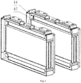
FIG. 1 is an exploded view of a battery module according to a first embodiment. -
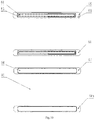
FIG. 2 is a side view of a cell separator of the battery module according to the first embodiment. -
FIG. 3 is a schematic diagram of a side of a first surface in a small component of the battery module according to the first embodiment. -
FIG. 4 is a schematic diagram of a side of a second surface in the small component of the battery module according to the first embodiment. -
FIG. 5 is an exploded view of a battery module according to a second embodiment. -
FIG. 6 is a schematic diagram of a cell separator of the battery module according to the second embodiment. -
FIG. 7 andFIG. 8 are schematic diagrams of the cell separator of the battery module according to a third embodiment. -
FIG. 9 andFIG. 10 are schematic diagrams of the cell separator of the battery module according to a fourth embodiment. -
FIG. 11 is a schematic diagram of the cell separator of the battery module according to a fifth embodiment. - In the drawings, 1 refers to wire harness, 2 refers to upper cover, 3 refers to connecting sheet, 4 refers to electrical separator, 5 refers to side plate, 6 refers to cell separator, 61 refers to side opening, 62 refers to UV glue coating area, 63 refers to glue overflow groove, 64 refers to reference plane boss, 65 refers to expansion area, 66 refers to first surface, 67 refers to second surface, 68 refers to first separator, 69 refers to second separator, 681 refers to cell separator of the first embodiment, 682 refers to cell separator of the second embodiment, 683 refers to cell separator of the third embodiment, 685 refers to cell separator of the fourth embodiment, 687 refers to cell separator of the fifth embodiment, 7 refers to UV glue, 8 refers to cell, 81 refers to cell pole, and 9 refers to end plate.
- Optimal embodiments of the present invention
- The technical schemes in the embodiments of the present invention will be described clearly and completely hereinafter with reference to the accompanying drawings in the embodiments of the present invention. Apparently, the embodiments described are merely some but not all of the embodiments of the present invention. Based on the embodiments of the present invention, all other embodiments obtained by those of ordinary skills in the art without going through any creative work belong to the scope of protection of the present invention.
- It should be understood that the terms used for indicating the orientation or position, such as "upper", "lower", "left", "right", and the like, are all descriptions made according to the orientation or position of the accompanying drawings for the convenience of those skilled in the art to understand the technical schemes, and do not limit that the present invention can only be designed according to the orientation or position.
- As shown in
FIG. 1 to FIG. 11 , the embodiment of the present invention provides a battery module, which comprises a cell (8), a cell separator (6) and UV glue (7), wherein the cell (8) and the cell separator (6) are fixed through the UV glue (7) to form a separate small component, and a plurality of the small components are stacked along a thickness direction of the cells to form a cell body of the battery module. - Further, a shape of the cell separator (6) comprises an I-shape, a hollow-square shape, a regular U-shape, an inverted U-shape, a two-vertical-strip shape, a two-horizontal-strip shape and a four-point shape.
- Further, the cell separator (6) is made of plastic capable of transmitting ultraviolet light.
- Further, a body of the cell separator (6) is provided with a first surface (66) and a second surface (67), and the first surface (66) of the body of the cell separator (6) is provided with a UV glue coating area (62) and a glue overflow groove (63).
- Further, the UV glue coating area (63) is arranged on the first surface (66) according to the following manners or combinations of a four-corner manner, a loop manner, a two-horizontal-strip manner, a two-vertical-strip manner, a regular U-shape manner and an inverted U-shape manner.
- Further, the glue overflow groove (63) surrounds the UV glue coating area (62).
- Further, the second surface (67) of the body of the cell separator (6) is provide with a reference plane boss (64).
- Further, the UV glue coating area (62) corresponds to the reference plane boss (64).
- Further, a shape of the reference plane boss (64) is a rectangle, a C-shape, a W-shape, an O-shape, a Y-shape, a circle or a triangle.
- Further, edges of the cell separators (6) in adjacent small components are not contacted with each other.
- Further, the cell separators (6) in adjacent small components are reserved with cell expansion areas (65) on central positions of the cells.
- Further, an adhesion thickness of the UV glue (7) is adjustable.
- Several embodiments of the cell separator will be described in detail hereinafter.
- As the first embodiment of the present invention, as shown in
FIG. 1 , the battery module is composed of a cell separator (681) of the first embodiment, and as shown inFIG. 2 to FIG. 4 , the cell separator (681) of the first embodiment is made of a PC material and is in a rectangle. An oval side opening (61) is arranged at a center of a side edge of the cell separator (6), the body of the cell separator (6) is completely hollowed out on a position corresponding to the side opening (61) to form the expansion area (65), and the side plate (5) of the battery module is provided with a vent on the position corresponding to the side opening (61) of the cell separator. When the battery module is completely assembled, cooling gas may pass through the battery module through the vent on the side plate (5) of the battery module and is directly contacted with the cell (7) to cool the cell (7). - The expansion area (65) traverses the cell separator (6), and a width of the expansion area is the same as a height of the side opening (61), thereby reserving a space for expansion of the cell (7). When the cell (7) is heated and expanded during operation, the cell (7) will be deformed along the thickness direction of the cells, and the expansion area (65) is able to reserve an enough space for the deformation, thereby reducing an effect of the deformation of the cell (7) on the whole battery module.
- Four UV glue coating areas (63) and four glue overflow grooves (62) are respectively arranged on four vertex positions on one side of the cell separator (6), the UV glue coating areas (63) are in a rectangle, and the other side of the cell separator (6) is provided with the reference plane bosses (64) on positions corresponding to the UV glue coating areas (63). When the battery module is assembled, the glue overflow grooves (62) may accommodate redundant UV glue to prevent overflow of the UV glue from affecting new energy of the battery module, and the reference plane boss (64) may further extrude a contact portion between the cell (7) and the UV glue, thus improving an adhesion stability between the cell (7) and the cell separator (6).
- Positioning devices (66) are respectively arranged at two ends of a top of the cell separator (6), which are able to provide positioning assistance for two adjacent cell separators (6) when the battery module is assembled. The top of the cell separator (6) is provided with an exhaust channel mounting and fixing site (67) on a position corresponding to an explosion-proof valve of the cell (7). After all the cells (7) and the cell separators (6) are assembled, an exhaust channel is assembled in the exhaust channel mounting and fixing site (67), and gas ejected from the explosion-proof valve of the cell (7) is collected to prevent an electrolyte from splashing around, thus further improving the safety of the whole battery module.
- As another embodiment of the present invention, as shown in
FIG. 5 , the battery module is composed of a cell separator (682) of the second embodiment. In the embodiment, the cell separator (682) of the second embodiment may be replaced by a cell separator (683) of the third embodiment, a cell separator (685) of the fourth embodiment or a fifth cell separator (687) according to a condition, and the cell separator of each embodiment will be further described hereinafter. - As shown in
FIG. 5 , the cell separator (682) of the second embodiment has a rectangular frame structure as a whole, and a center of the cell separator (6) is the expansion area, thus reserving a space for expansion of the cell (7). When the cell (7) is heated and expanded during operation, the cell (7) will be deformed along the thickness direction of the cells, and the expansion area (65) is able to reserve an enough space for the deformation, thus reducing an effect of the deformation of the cell (7) on the whole battery module. - Two UV glue coating areas (63) and two glue overflow grooves (62) are respectively arranged on two wide edge positions of the cell separator (6), the UV glue coating areas (63) are in a rectangle, and the other side of the cell separator (6) is provided with the reference plane bosses (64) on positions corresponding to the UV glue coating areas (63). When the battery module is assembled, the glue overflow grooves (62) may accommodate redundant UV glue to prevent overflow of the UV glue from affecting new energy of the battery module, and the reference plane boss (64) may further extrude a contact portion between the cell (7) and the UV glue, thus improving an adhesion stability between the cell (7) and the cell separator (6).
- As shown in
FIG. 7 andFIG. 8 , the cell separator (683) of the third embodiment has a U-shaped frame structure as a whole, and an opening position of the cell separator (6) is the expansion area, thereby reserving a space for expansion of the cell (7). When the cell (7) is heated and expanded during operation, the cell (7) will be deformed along the thickness direction of the cells, and the expansion area (65) is able to reserve an enough space for the deformation, thereby reducing an effect of the deformation of the cell (7) on the whole battery module. - Two UV glue coating areas (63) and two glue overflow grooves (62) are respectively arranged on two side edge positions of the cell separator (6), the UV glue coating areas (63) are in a rectangle, and the other side of the cell separator (6) is provided with the reference plane bosses (64) on positions corresponding to the UV glue coating areas (63). When the battery module is assembled, the glue overflow grooves (62) may accommodate redundant UV glue to prevent overflow of the UV glue from affecting new energy of the battery module, and the reference plane boss (64) may further extrude a contact portion between the cell (7) and the UV glue, thereby improving an adhesion stability between the cell (7) and the cell separator (6).
- It should be noted that the cell separator (6) shown in
FIG. 7 is a U-shaped frame with an upward opening, and the cell separator (6) shown inFIG. 8 is a U-shaped frame with a downward opening. The two U-shaped frames have the same structure but different opening directions, and similarly, the U-shaped frame may also have a left or right opening. - As shown in
FIG. 9 andFIG. 10 , the cell separator (685) of the fourth embodiment is composed of the first separator (68) and the second separator (69), and the expansion area is formed between the first separator (68) and the second separator (69), thus reserving a space for expansion of the cell (7). When the cell (7) is heated and expanded during operation, the cell (7) will be deformed along the thickness direction of the cells, and the expansion area (65) is able to reserve an enough space for the deformation, thus reducing an effect of the deformation of the cell (7) on the whole battery module. - A layout scheme is shown in
FIG. 9 , the first separator (68) and the second separator (69) have a same height and are respectively adhered to two side edges of the cell (7). Each separator is provided with one UV adhesive coating area (63) and one glue overflow groove (62). The UV glue coating area (63) is in a rectangle, and the other side of the cell separator (6) is provided with the reference plane boss (64) on a position corresponding to the UV glue coating area (63). When the battery module is assembled, the glue overflow groove (62) may accommodate redundant UV glue to prevent overflow of the UV glue from affecting new energy of the battery module, and the reference plane boss (64) may further extrude a contact portion between the cell (7) and the UV glue, thereby improving an adhesion stability between the cell (7) and the cell separator (6). - Another layout scheme is shown in
FIG. 10 , the first separator (68) and the second separator (69) have a same length and are respectively adhered to two long edges of the cell (7), and each separator is provided with one UV glue coating area (63) and one glue overflow groove (62). The UV glue coating area (63) is in a rectangle, and the other side of the cell separator (6) is provided with the reference plane boss (64) on a position corresponding to the UV glue coating area (63). When the battery module is assembled, the glue overflow groove (62) may accommodate redundant UV glue to prevent overflow of the UV glue from affecting new energy of the battery module, and the reference plane boss (64) may further extrude a contact portion between the cell (7) and the UV glue, thus improving an adhesion stability between the cell (7) and the cell separator (6). - As shown in
FIG. 11 , the cell separator (687) of the fifth embodiment is composed of four small components, and the expansion area is formed among the four small components, thus reserving a space for expansion of the cell (7). When the cell (7) is heated and expanded during operation, the cell (7) will be deformed along the thickness direction of the cells, and the expansion area (65) is able to reserve an enough space for the deformation, thus reducing an effect of the deformation of the cell (7) on the whole battery module. - The small components (610) are respectively attached to four vertices of the cell, and each small component (610) is provided with one UV glue coating area (63) and one glue overflow groove (62). The UV glue coating area (63) is in a rectangle, and the other side of the cell separator (6) is provided with the reference plane boss (64) on a position corresponding to the UV glue coating area (63). When the battery module is assembled, the glue overflow groove (62) may accommodate redundant UV glue to prevent overflow of the UV glue from affecting new energy of the battery module, and the reference plane boss (64) may further extrude a contact portion between the cell (7) and the UV glue, thus improving an adhesion stability between the cell (7) and the cell separator (6).
- Those described above are the preferred embodiments of the present invention, and it should be pointed out that those of ordinary skills in the art may further make improvements and decorations without departing from the principle of the present invention, and these improvements and decorations should also be regarded as the scope of protection of the present invention.
Claims (12)
- A battery module, comprising a cell, a cell separator and UV glue, wherein the cell and the cell separator are fixed through the UV glue to form a separate small component, and a plurality of the small components are stacked along a thickness direction of the cells to form a cell body of the battery module.
- The battery module according to claim 1, wherein a shape of the cell separator comprises an I-shape, a hollow-square shape, a regular U-shape, an inverted U-shape, a two-vertical-strip shape, a two-horizontal-strip shape and a four-point shape.
- The battery module according to claim 2, wherein the cell separator is made of plastic capable of transmitting ultraviolet light.
- The battery module according to claim 2, wherein a body of the cell separator is provided with a first surface and a second surface, and the first surface of the body of the cell separator is provided with a UV glue coating area and a glue overflow groove.
- The battery module according to claim 4, wherein the UV glue coating area is arranged on the first surface according to the following manners or combinations of a four-corner manner, a loop manner, a two-horizontal-strip manner, a two-vertical-strip manner, a regular U-shape manner and an inverted U-shape manner.
- The battery module according to claim 4, wherein the glue overflow groove is configured to surround the UV glue coating area.
- The battery module according to claim 4, wherein the second surface of the body of the cell separator is provide with a reference plane boss.
- The battery module according to claim 4 or 7, wherein the UV glue coating area is configured to correspond to the reference plane boss.
- The battery module according to claim 4 or 7, wherein a shape of the reference plane boss is a rectangle, a C-shape, a W-shape, an O-shape, a Y-shape, a circle or a triangle.
- The battery module according to claim 1, wherein edges of the cell separators in adjacent small components are not contacted with each other.
- The battery module according to claim 1, wherein the cell separators in adjacent small components are reserved with cell expansion areas at central positions of the cells.
- The battery module according to claim 1, wherein an adhesion thickness of the UV glue is adjustable.
Applications Claiming Priority (3)
| Application Number | Priority Date | Filing Date | Title |
|---|---|---|---|
| CN201910731734.XA CN111725449B (en) | 2019-08-08 | 2019-08-08 | Battery module |
| CN201921281107.2U CN210379158U (en) | 2019-08-08 | 2019-08-08 | Battery module |
| PCT/CN2019/104511 WO2021022606A1 (en) | 2019-08-08 | 2019-09-05 | Battery module |
Publications (2)
| Publication Number | Publication Date |
|---|---|
| EP3800687A1 true EP3800687A1 (en) | 2021-04-07 |
| EP3800687A4 EP3800687A4 (en) | 2022-04-13 |
Family
ID=74502825
Family Applications (1)
| Application Number | Title | Priority Date | Filing Date |
|---|---|---|---|
| EP19926733.7A Pending EP3800687A4 (en) | 2019-08-08 | 2019-09-05 | BATTERY MODULE |
Country Status (3)
| Country | Link |
|---|---|
| EP (1) | EP3800687A4 (en) |
| JP (1) | JP7105920B2 (en) |
| WO (1) | WO2021022606A1 (en) |
Families Citing this family (6)
| Publication number | Priority date | Publication date | Assignee | Title |
|---|---|---|---|---|
| CN115347296B (en) * | 2021-05-14 | 2024-12-03 | 中创新航科技股份有限公司 | Battery box body, battery assembly and battery assembly method |
| WO2023085706A1 (en) * | 2021-11-15 | 2023-05-19 | 주식회사 엘지에너지솔루션 | Battery module and battery pack including same |
| WO2023171117A1 (en) * | 2022-03-11 | 2023-09-14 | 株式会社Gsユアサ | Power storage device |
| CN114927818B (en) * | 2022-05-16 | 2024-04-19 | 北京科易动力科技有限公司 | Battery module and battery pack |
| CN115157700A (en) * | 2022-06-17 | 2022-10-11 | 宁波市鄞州稳泰自动化装备有限公司 | A rubber coating device for special-shaped workpiece |
| EP4668421A3 (en) * | 2024-05-24 | 2026-01-21 | Samsung Sdi Co., Ltd. | Secondary battery and battery module including the same |
Family Cites Families (7)
| Publication number | Priority date | Publication date | Assignee | Title |
|---|---|---|---|---|
| US20150037662A1 (en) | 2013-07-30 | 2015-02-05 | Johnson Controls Technology Company | System and method for sealing a battery cell |
| CN203871383U (en) * | 2014-03-28 | 2014-10-08 | 宁德时代新能源科技有限公司 | Battery pack structure |
| KR101777798B1 (en) | 2014-10-31 | 2017-09-12 | 주식회사 엘지화학 | Battery module and Method for manufacturing the same |
| CN204271146U (en) * | 2014-12-22 | 2015-04-15 | 深圳市诺贝诺胶接技术有限公司 | A kind of electric automobile power battery module |
| US9620764B2 (en) * | 2015-01-05 | 2017-04-11 | Johnson Controls Technology Company | Battery module cooling fins and footings system and method |
| CN106450406A (en) | 2015-08-07 | 2017-02-22 | 宁德时代新能源科技股份有限公司 | Battery module |
| CN108282570B (en) * | 2018-01-22 | 2020-05-08 | Oppo广东移动通信有限公司 | Electronic device |
-
2019
- 2019-09-05 EP EP19926733.7A patent/EP3800687A4/en active Pending
- 2019-09-05 WO PCT/CN2019/104511 patent/WO2021022606A1/en not_active Ceased
- 2019-09-05 JP JP2020563713A patent/JP7105920B2/en active Active
Also Published As
| Publication number | Publication date |
|---|---|
| WO2021022606A1 (en) | 2021-02-11 |
| EP3800687A4 (en) | 2022-04-13 |
| JP7105920B2 (en) | 2022-07-25 |
| JP2021535538A (en) | 2021-12-16 |
Similar Documents
| Publication | Publication Date | Title |
|---|---|---|
| EP3800687A1 (en) | Battery module | |
| CN110165117B (en) | Battery pack, vehicle and energy storage device | |
| JP6449438B2 (en) | Power supply device and vehicle equipped with power supply device | |
| US10333185B2 (en) | Battery module including cooling structure in which coolant channel is minimally bent | |
| EP4131612B1 (en) | Power supply device, and vehicle and electrical storage device each equipped with same | |
| CN111725449B (en) | Battery module | |
| US20220352573A1 (en) | Battery cell, battery, power consumption device, and battery manufacturing method and device | |
| EP3890052A1 (en) | Battery module | |
| US9484607B2 (en) | Battery module | |
| US12142747B2 (en) | Heat-exchanging component, method for manufacturing heat-exchanging component, system of manufacturing heat-exchanging component, battery and electricity-consuming apparatus | |
| US20180198102A1 (en) | Tray for activating battery cell comprising elastic member | |
| KR20240125030A (en) | Batteries and electrical devices | |
| US10903472B2 (en) | Electrode tab coupling member and electrode tab coupling assembly comprising same | |
| US20120214045A1 (en) | Battery module | |
| WO2021199493A1 (en) | Power supply device, vehicle provided with same, and power storage device | |
| US20240322336A1 (en) | Casing of battery, battery and electricity-consuming apparatus | |
| WO2020026964A1 (en) | Power supply device, vehicle having same, and buffer | |
| US12500302B2 (en) | Power source device, and vehicle and power storage device each equipped with same | |
| US20250233289A1 (en) | Battery cell, battery, and electric device | |
| CN210379158U (en) | Battery module | |
| JP6797969B2 (en) | Battery module and battery pack | |
| CN116249652B (en) | Battery cells, batteries and electrical equipment | |
| CN119833768B (en) | Support devices, welding equipment, battery cells, battery devices and power devices | |
| CN223124154U (en) | Battery cell | |
| CN223842991U (en) | Liquid cooling unit, battery module assembly, battery pack and vehicle |
Legal Events
| Date | Code | Title | Description |
|---|---|---|---|
| STAA | Information on the status of an ep patent application or granted ep patent |
Free format text: STATUS: UNKNOWN |
|
| STAA | Information on the status of an ep patent application or granted ep patent |
Free format text: STATUS: THE INTERNATIONAL PUBLICATION HAS BEEN MADE |
|
| PUAI | Public reference made under article 153(3) epc to a published international application that has entered the european phase |
Free format text: ORIGINAL CODE: 0009012 |
|
| STAA | Information on the status of an ep patent application or granted ep patent |
Free format text: STATUS: REQUEST FOR EXAMINATION WAS MADE |
|
| 17P | Request for examination filed |
Effective date: 20201105 |
|
| AK | Designated contracting states |
Kind code of ref document: A1 Designated state(s): AL AT BE BG CH CY CZ DE DK EE ES FI FR GB GR HR HU IE IS IT LI LT LU LV MC MK MT NL NO PL PT RO RS SE SI SK SM TR |
|
| AX | Request for extension of the european patent |
Extension state: BA ME |
|
| REG | Reference to a national code |
Ref country code: DE Ref legal event code: R079 Free format text: PREVIOUS MAIN CLASS: H01M0002020000 Ipc: H01M0050202000 |
|
| A4 | Supplementary search report drawn up and despatched |
Effective date: 20220315 |
|
| RIC1 | Information provided on ipc code assigned before grant |
Ipc: H01M 50/209 20210101ALI20220309BHEP Ipc: H01M 50/202 20210101AFI20220309BHEP |
|
| DAV | Request for validation of the european patent (deleted) | ||
| DAX | Request for extension of the european patent (deleted) | ||
| RAP3 | Party data changed (applicant data changed or rights of an application transferred) |
Owner name: SUNWODA MOBILITY ENERGY TECHNOLOGY CO., LTD. |
|
| STAA | Information on the status of an ep patent application or granted ep patent |
Free format text: STATUS: EXAMINATION IS IN PROGRESS |
|
| 17Q | First examination report despatched |
Effective date: 20240805 |