EP3800544B1 - Hardware für gleitkommamultiplikation unter verwendung von zergliederten komponentennummern - Google Patents
Hardware für gleitkommamultiplikation unter verwendung von zergliederten komponentennummern Download PDFInfo
- Publication number
- EP3800544B1 EP3800544B1 EP20198355.8A EP20198355A EP3800544B1 EP 3800544 B1 EP3800544 B1 EP 3800544B1 EP 20198355 A EP20198355 A EP 20198355A EP 3800544 B1 EP3800544 B1 EP 3800544B1
- Authority
- EP
- European Patent Office
- Prior art keywords
- floating point
- component
- vector
- multiplication
- point number
- Prior art date
- Legal status (The legal status is an assumption and is not a legal conclusion. Google has not performed a legal analysis and makes no representation as to the accuracy of the status listed.)
- Active
Links
Images



Classifications
-
- G—PHYSICS
- G06—COMPUTING OR CALCULATING; COUNTING
- G06F—ELECTRIC DIGITAL DATA PROCESSING
- G06F7/00—Methods or arrangements for processing data by operating upon the order or content of the data handled
- G06F7/38—Methods or arrangements for performing computations using exclusively denominational number representation, e.g. using binary, ternary, decimal representation
- G06F7/48—Methods or arrangements for performing computations using exclusively denominational number representation, e.g. using binary, ternary, decimal representation using non-contact-making devices, e.g. tube, solid state device; using unspecified devices
- G06F7/483—Computations with numbers represented by a non-linear combination of denominational numbers, e.g. rational numbers, logarithmic number system or floating-point numbers
- G06F7/487—Multiplying; Dividing
- G06F7/4876—Multiplying
-
- G—PHYSICS
- G06—COMPUTING OR CALCULATING; COUNTING
- G06F—ELECTRIC DIGITAL DATA PROCESSING
- G06F17/00—Digital computing or data processing equipment or methods, specially adapted for specific functions
- G06F17/10—Complex mathematical operations
- G06F17/16—Matrix or vector computation, e.g. matrix-matrix or matrix-vector multiplication, matrix factorization
-
- G—PHYSICS
- G06—COMPUTING OR CALCULATING; COUNTING
- G06F—ELECTRIC DIGITAL DATA PROCESSING
- G06F7/00—Methods or arrangements for processing data by operating upon the order or content of the data handled
- G06F7/38—Methods or arrangements for performing computations using exclusively denominational number representation, e.g. using binary, ternary, decimal representation
- G06F7/48—Methods or arrangements for performing computations using exclusively denominational number representation, e.g. using binary, ternary, decimal representation using non-contact-making devices, e.g. tube, solid state device; using unspecified devices
- G06F7/483—Computations with numbers represented by a non-linear combination of denominational numbers, e.g. rational numbers, logarithmic number system or floating-point numbers
- G06F7/485—Adding; Subtracting
-
- G—PHYSICS
- G06—COMPUTING OR CALCULATING; COUNTING
- G06N—COMPUTING ARRANGEMENTS BASED ON SPECIFIC COMPUTATIONAL MODELS
- G06N3/00—Computing arrangements based on biological models
- G06N3/02—Neural networks
Definitions
- a whole class of complex artificial intelligence problems can be solved using neural networks.
- One common operation required by many neural networks is a multiplication operation, for example, when performing matrix operations. Since artificial intelligence problems are often computationally and data intensive, hardware solutions are often beneficial for improving performance. However, the hardware to implement a floating-point multiplication operation is expensive. Moreover, different neural networks can require different number formats, which in turn can each have different hardware requirements. It is a technical challenge to create a hardware platform compatible with multiple number formats and capable of efficiently performing matrix multiplication operations. Therefore, there exists a need for a high throughput matrix multiplication scheme that is compatible with multiple number formats without introducing significant hardware complexity and expense.
- the invention discloses a processor system, comprising: one or more logic units configured to:
- the one or more logic units may be configured to identify that the first floating number is in a first format, wherein a number of bits used to represent the first format may exceed a number of bits supported by hardware capabilities of each individual one of the one or more multiplication units.
- the 21-bit floating point unit may utilize 1 bit for a sign bit, 9 bits for an exponent component, and 11 bits for a mantissa component.
- each of the one or more multiplication units may be able to perform an FP16 and a BFloat16 floating point multiplication operation.
- hardware capabilities of the one or more multiplication units may not support performing a 32-bit floating-point multiplication operation using only a single multiplication operation.
- the system may further comprise a matrix compute engine that includes a plurality of vector units.
- each of the plurality of vector units may include a vector multiply unit and a vector adder unit and the the vector multiply unit may further include the one or more multiplication units, and the vector adder unit may further be an adder tree.
- a sum of each component number of the first group of the plurality of component numbers may be equal to the first floating point number.
- a mantissa component of a component number of the first group of the plurality of component numbers may be normalized to remove leading zeros and a 1-bit binary integer.
- the first group of the plurality of component numbers may include a first component number and a second component number, and wherein a sum of the first component number and the second component number is equal to the first floating point number.
- the first component number may be associated with 11-bits of a mantissa component of the first floating point number and the second component number may be associated with a remaining 12-bits of the mantissa component of the first floating point number, or, alternatively, the first component number may represent a most significant bit sequence of the first floating point number and the second component number may represent a least significant bit sequence of the first floating point number, and the most significant bit sequence may be associated with a fewer number of bits of a mantissa component of the first floating point number than the least significant bit sequence.
- the one or more logic units may further be configured to:
- the result of multiplying the first floating point number with the second floating point number may be used at least in part to apply a neural network model to an artificial intelligence problem.
- the present invention discloses a method comprising:
- the invention can be implemented in numerous ways, including as a process; an apparatus; a system; a composition of matter; a computer program product embodied on a computer readable storage medium; and/or a processor, such as a processor configured to execute instructions stored on and/or provided by a memory coupled to the processor.
- these implementations, or any other form that the invention may take, may be referred to as techniques.
- the order of the steps of disclosed processes may be altered within the scope of the invention.
- a component such as a processor or a memory described as being configured to perform a task may be implemented as a general component that is temporarily configured to perform the task at a given time or a specific component that is manufactured to perform the task.
- the term 'processor' refers to one or more devices, circuits, and/or processing cores configured to process data, such as computer program instructions.
- a processor system for improving the efficiency and performance of floating point multiplication operations is disclosed.
- multiplication support is implemented for a variety of formats including different floating point formats such as FP32, BFloat16, and FP16.
- the number of bits used to represent a supported floating point number may exceed the number of bits supported by the hardware capabilities of a multiplication unit.
- a multiply unit may support 21-bit operands but utilizing the disclosed techniques, the processor system supports 32-bit floating point multiplication operations.
- a processor instruction specifies a first and second floating point number as multiplication operands. In the event the floating point operands exceed the number of bits supported by the hardware capabilities of a multiplication unit, each floating point operand is decomposed into a group of component numbers.
- the component numbers are sized based on the capabilities of the multiplication units.
- a processor system that includes FP21 multiplication units can utilize FP21 component numbers.
- a 32-bit floating point multiplication operation can not be performed by an FP21 multiplication unit using only a single multiplication operation.
- a 32-bit floating point can be decomposed into multiple FP21 numbers.
- the different component numbers of the first and second floating point operands are multiplied to determine intermediate multiplication results.
- the different component numbers of the first floating point number can be loaded into a vector operand.
- a corresponding vector operand with duplicates of the component number is loaded and a vector multiply operation is performed to determine a vector of intermediate multiplication results.
- the resulting intermediate multiplication results are summed to determine the effective result of multiplying the first and second floating point numbers.
- a vector adder unit such as a vector adder tree can be used to sum the intermediate multiplication results.
- a processor system comprises one or more logic units and one or more multiplication units.
- one or more logic units receive a processor instruction corresponding to a matrix multiplication operation and prepare operations and operands for one or more multiplication units to perform multiplication operations on the prepared operands.
- the one or more logic units are configured to receive a processor instruction identifying a first floating point number to be multiplied with a second floating point number.
- a floating point multiply instruction may specify two operands to be multiplied.
- the operands may be in one of many different formats, such as FP32, BFloat16, FP16, or another number format. The different number formats may require a different number of bits to represent a number.
- the first floating point number is decomposed into a first group of a plurality of component numbers.
- the number of bits used to represent the first floating point number is greater than the number of bits used to represent any component number in the first group of the plurality of component numbers.
- an FP32 number expressed using 32-bits can be decomposed into two (or more) component numbers, where each component number uses fewer bits than an FP32 number.
- the component numbers are 21-bit numbers, an FP21 number, and/or another appropriate number format.
- the second floating point number is decomposed into a second group of a plurality of component numbers, wherein the number of bits used to represent the second floating point number is greater than the number of bits used to represent any component number in the second group of the plurality of component numbers.
- a second floating point number that is an FP32 number and expressed using 32-bits can be decomposed into two (or more) component numbers, where each component number uses fewer bits than an FP32 number.
- the groups of component numbers can be used as operands for one or more multiplication units.
- the one or more multiplication units are configured to multiply the component numbers of the first group with the component numbers of the second group to determine intermediate multiplication results.
- the intermediate multiplication results are summed together to determine an effective result that represents a result of multiplying the first floating point number with the second floating point number. For example, each component of the first floating point number is multiplied against each component of the second floating point number to create a set of partial multiplication results using one or more vector multiply units of a matrix processor.
- the partial results can be summed together using one or more vector adder units of the matrix processor to determine the multiplication result of multiplying the first floating point number with the second floating point number.
- the first floating point number and the second floating point number use more bits than supported by any one of the multiplication units, the decomposed components are supported by the multiplication units and are used to determine the effective multiplication result.
- the component numbers of the first and second floating point numbers allocate an additional bit for each of their respective exponents to avoid loss of accuracy, for example, due to a potential underflow when adding exponents.
- an FP32 number using an 8-bit exponent can be decomposed into FP21 numbers using 9-bit exponents.
- at least the partial results are calculated using component numbers with an additional exponent bit, such as with FP21 numbers using 9-bit exponents when multiplying two FP32 numbers having 8-bit exponents.
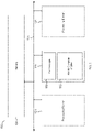
- FIG. 1 is a block diagram illustrating an embodiment of a system for solving artificial intelligence problems using a neural network.
- system 100 may be applied to use a neural network to solve problems such as image recognition and recommendation system matches.
- system 100 includes multiple processing elements such as processing elements 101, 111, and 121 connected to memory unit 131 via bus 151.
- system 100 may include fewer or more processing elements.
- the number of processing elements can be scaled up or down depending on the intended computational and data requirements.
- the processing elements, such as 101, 111, and 121 are communicatively connected to one another and/or memory unit 131 via bus 151.
- the memory unit may be a last level cache (LLC) and/or may be implemented using static random-access memory (SRAM).
- LLC last level cache
- SRAM static random-access memory
- Each processing element may be utilized by system 100 to perform matrix compute operations such as matrix multiplications including floating point multiplications.
- a communication bus such as bus 151, may be used to transmit processing element instructions and optional instruction arguments.
- a matrix operation and matrix operands may be transmitted to a processing element, such as processing elements 101, 111, and/or 121, via bus 151.
- Additional processing element instructions may include multiplication operation instructions such as floating point multiplication operation instructions.
- a large, complex artificial intelligence problem can be solved using system 100 by subdividing the problem into smaller sub-problems. The smaller sub-problems can be assigned and distributed to different processing elements. The results of the smaller sub-problems can be merged to determine the solution to the larger and more complex problem. In some scenarios, the sub-problems are solved in parallel and/or in pipelined stages. In some scenarios, the result from a first processing element is fed as an input to a second processing element.
- each processing element of system 100 includes at least a control logic unit and a matrix compute engine.
- processing element 111 includes control logic 113 and matrix compute engine 115.
- Processing elements 101 and 121 are shown as dotted boxes and some details of processing elements 101 and 121 are not shown.
- the control logic unit of a processing element is used to control the operation of the processing element including the operation of the processing element's matrix compute engine.
- control logic 113 processes instructions directed to processing element 111 via communication bus 151.
- a processing element instruction may include a floating point multiplication instruction.
- control logic 113 determines how to perform the floating point multiplication using matrix compute engine 115, including how to decompose floating point number operands into component numbers. In some embodiments, control logic 113 receives processing element instructions via bus 151 and can be used to initiate retrieving and/or writing data from/to memory 131.
- matrix compute engine 115 is a hardware matrix compute engine for performing matrix operations including operations related to floating point multiplication, matrix multiplication, and/or convolution operations.
- matrix compute engine 115 may be a matrix engine for performing dot product operations requiring floating point multiplications and addition operations.
- the convolution operations supported include depthwise, groupwise, normal, regular, pointwise, two-dimensional, and/or three-dimensional convolutions, among others.
- matrix compute engine 115 may receive a first input matrix such as a subset of a large image and a second input matrix such as a filter, kernel, or convolution matrix, etc. to apply to the first input matrix.
- Matrix compute engine 115 can be used to perform a convolution operation using the two input matrices to determine a resulting output matrix.
- matrix compute engine 115 may include input and/or output buffers for loading input data matrices or vectors and writing out a result data matrix or vector.
- matrix compute engine 115 includes multiple vector units and each vector unit includes a vector multiply unit and a vector adder unit.
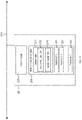
- FIG. 2 is a block diagram illustrating an embodiment of a processing element for solving artificial intelligence problems using a neural network.
- processing element 201 is communicatively connected to bus 251.
- Processing element 201 includes control logic 203 and matrix compute engine 205.
- Matrix compute engine 205 includes vector units 211, 221, 231, and 241.
- a matrix compute engine may include more or fewer vector units.
- a matrix compute engine may include 32 vector units, each capable of processing two 32-element vectors.
- each vector unit includes a vector multiply unit and a vector adder unit.
- vector unit 211 includes vector multiply unit 213 and vector adder unit 215.
- processing element 201 is processing element 101, 111, and/or 121 of Figure 1 .
- control logic 203 and matrix compute engine 205 are, respectively, control logic 113 and matrix compute engine 115 of Figure 1 .
- matrix compute engine 205 receives input matrix (or vector) operands to perform matrix operations.
- matrix compute engine 205 may receive one or more data input vectors corresponding to a portion of an image and at least one weight input vector corresponding to a filter matrix.
- the input vectors such as input data and weight vectors, may be passed as arguments to a vector unit, such as one of vector units 211, 221, 231, and 241, of matrix compute engine 205.
- the vector unit of matrix compute engine 205 may determine a matrix result, such as a dot product result, using a data input vector and weight input vector pair.
- matrix compute engine 205 includes 32 vector units.
- Each vector unit may take two 32-element vectors as arguments and can each determine a 32-element vector result.
- the result is a single element result and taken across all vector units of matrix compute engine 205, the results are an output vector result.
- the output results are determined by accumulating partial vector results across multiple vector unit operations. For example, a multiplication operation can be decomposed into multiple multiplication operations and the results summed.
- the number of vector units of matrix compute engine 205 can vary as can the vector unit lengths and element sizes.
- elements may be 4-bits, 8-bits, 2-byte, 4-bytes, or another appropriate size. Depending on the capabilities of the vector unit, different element sizes can be natively supported without decomposing the element into components.
- each vector unit of matrix compute engine 205 receives two vector operands and can perform one or more vector operations.
- a vector unit can compute the result of multiple multiply operations by multiplying each element of the first input vector with a corresponding element of a second input vector.
- the resulting multiplication results can be accumulated and used for future operations, such as summing partial results.
- a vector unit result can be accumulated and used as an operand to a subsequent operation performed by the vector unit.
- each vector unit of matrix compute engine 205 such as vector units 211, 221, 231, or 241, includes both a multiply unit and an adder unit.
- Each vector multiply unit of a vector unit such as vector multiply unit 213, is configured to multiply corresponding elements received via input vector operands.
- the result is a vector of multiplication results. For example, for two 32-byte input vectors, the result of a vector multiply unit is a vector of 32 multiplication results. The first element from a first input vector is multiplied with the first element of a second input vector. Similarly, the second element from the first input vector is multiplied with the second element of the second input vector.
- the largest supported element size may be a 21-bit number, such as a 21-bit floating point number, or another appropriate size.
- the vector of multiplication results is passed to a vector adder unit of the vector unit.
- vector multiply unit 213 can pass its multiplication results to vector adder unit 215.
- Vector adder unit 215 can be used for addition operations such as summing partial results, computing at least in part a dot product result, or other appropriate functionality.
- each vector adder unit of a vector unit is configured to compute addition operations using elements from an input vector. For example, the sum of selected elements from a vector of multiplication results computed by vector multiply unit 213 is computed by vector adder unit 215.
- the result of a vector adder unit is a dot product of the vectors used as input to the corresponding vector multiply unit.
- each vector adder unit, such as vector adder unit 215, is implemented as an adder tree. For example, the top level of an adder tree may add pairs of elements to determine a set of partial sums, such as adding elements 0 and 1 to determine a first partial sum and elements 2 and 3 to determine a second partial sum, etc.
- Each subsequent level may sum pairs of partial sums from the previous level until the last level computes a final result sum.
- any partial sums may be outputted as a result of the adder unit.
- each adder tree computes partial sums in parallel to arrive at a result sum. The parallel operation significantly improves the efficiency of summing a vector of numbers.
- multiple vector units can operate in parallel to compute multiple results in parallel, significantly improving the throughput of matrix compute engine 205.
- matrix compute engine 205 includes one or more accumulators, for example, to accumulate the results of each vector unit.
- an accumulator is included as part of a vector unit or as part of matrix compute engine 205 as appropriate.
- the accumulator(s) can be used to sum the results computed across multiple iterations of the vector units. For example, the result from one iteration of a vector unit can be stored in an accumulator and added to the result of the next iteration of the vector unit.
- the accumulator is a vector accumulator.
- the accumulator may be sized based on the size of an output vector of matrix compute engine 205.
- the accumulator results may be pushed to memory via bus 251.
- FIG. 3 is a flow chart illustrating an embodiment of a process for performing a floating point multiplication.
- a floating point multiplication operation using multiplication operands that exceed the number of bits of a hardware multiplier unit may be performed.
- each multiplication operand is decomposed into a component number supported by the hardware multiplier unit to compute partial results that are summed.
- a processing element is capable of supporting multiple floating point formats and consequently multiple types of neural network models while maintaining a high throughput and with minimal additional hardware modifications.
- the supported floating point multiplication operations can be used to solve artificial intelligence problems using a neural network that utilizes a floating point format that exceeds the native hardware capabilities of a matrix compute engine and its multiplier units.
- an FP32 floating point operation can be performed using a matrix compute engine with FP21 multipliers.
- the process of Figure 3 is performed in response to receiving a multiply operation instruction at a control unit of a processing element, such as processing elements 101, 111, and/or 121 of Figure 1 and/or processing element 201 of Figure 2 .
- a floating point multiply processor instruction is received.
- an FP32 floating point multiply operation instruction specifying two FP32 numbers is received at a control logic of a processing element.
- the multiply operation instruction may specify two 32-bit floating point numbers.
- the number of bits used by each operand may be 32-bits or another appropriate bit size that is larger than the number of bits supported by the hardware multipliers of the processing element.
- the instruction is a vector instruction. For example, two vectors of operands may be received and each element of a first vector is to be multiplied with a corresponding element of a second vector.
- the floating point formats are identified.
- the floating point format for the specified multiplication operands are identified and may include FP32, FP16, BFloat16, and/or other floating point formats.
- multiple different floating point formats are supported by the processing element.
- the hardware multipliers of the processing element can natively support one or more formats while other format(s) are supported via a decomposition process.
- a matrix compute engine with vector units that support FP21 elements can natively support FP16 and BFloat16 floating point formats without decomposing the operands into component numbers.
- Support for FP32 is implemented by decomposing the FP32 operands into FP21 numbers.
- the floating point format is specified by the multiply processor instruction.
- the floating point numbers are decomposed into component numbers.
- non-native floating point operands are decomposed into a group of native floating-point numbers.
- the vector unit of a matrix compute engine supports up to 21-bit floating point numbers natively.
- a 32-bit floating point operand is not natively supported and is decomposed into two or more 21-bit floating point operands. The sum of the decomposed components is equal to the original floating point operand.
- a floating point multiplication using the decomposed floating point component numbers is performed.
- the decomposed components of the floating point operands are used to first determine intermediate multiplication results.
- the intermediate multiplication results are then summed to determine a final floating point result.
- the intermediate multiplication results are performed by multipliers of a matrix compute engine such as vector multiply unit 213 of vector unit 211 of Figure 2 .
- the intermediate multiplication results can be summed using the adder units of a matrix compute engine such as vector adder unit 215 of vector unit 211 of Figure 2 .
- only a subset of the components are needed to determine the multiplication result.
- one or more component numbers representing the least significant bits of a floating point operand do not impact the multiplication result and are not needed.
- the floating point result is provided.
- the floating point result is provided to the next step for solving an artificial intelligence problem.
- the result is utilized to solve the next layer of a neural network and/or combined with results from other processing elements.
- the result is written back to memory such as memory 131 of Figure 1 where the result can be utilized by a subsequent operation.
- the floating point result provided at 309 suffers no loss in accuracy by decomposing the floating point operands into component numbers.
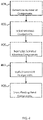
- Figure 4 is a flow chart illustrating an embodiment of a process for decomposing a floating point operand.
- the process of Figure 4 can be used to decompose a floating point number that exceeds the number of bits of a hardware multiplier unit into a component number compatible with the hardware multiplier unit.
- a control logic of a matrix compute engine with vector units that support up to 21-bit floating point numbers decomposes a 32-bit operand into two or more 21-bit floating point numbers.
- the 21-bit hardware multipliers are used to compute multiplication results using the 21-bit floating point numbers.
- the process of Figure 4 is performed at 305 of Figure 3 .
- the process is performed using the control logic of a processor element such as control logic 113 of Figure 1 and/or control logic 203 of Figure 2 .
- the number of components is determined. For example, the number of components a floating point operand is decomposed into is determined. In some embodiments, the number is based on the operands (or operand formats) supported by the available multiplier units. For example, an FP21 multiplier may support up to a 21-bit floating point component using a single sign bit, a 9-bit exponent, and an 11-bit mantissa. The 11-bits of the mantissa can represent the 11 most significant bits or any 12 consecutive least significant bits (the size of the supported hardware mantissa plus an additional bit represented as an implicit J-bit) of the original floating point operand.
- the number of components is determined based on how many component mantissas are required to represent the mantissa of the original floating point operand and the number of exponent bits supported by the multipliers matches the number of exponent bits of the floating point operand. For example, two FP21 components, each with an 11-bit mantissa, are used to represent a FP32 floating point operand with a 23-bit mantissa. As another example, three FP19 components, each with a 10-bit mantissa, are used to represent an FP32 floating point operand with a 23-bit mantissa.
- the floating point operand utilizes 8-bits for exponents and the supported hardware utilizes an additional bit, that is 9-bits, for exponents.
- the additional bit used by component numbers for exponents ensures accuracy, for example, by preventing underflow.
- underflow can be avoided when adding small exponent values.
- a lossy implementation may not utilize all of the least significant bits of the original floating point operand.
- mantissa components are selected.
- the mantissa of the floating point operand is split across multiple component numbers based on the number of components determined at 401.
- the mantissa components are selected by masking the mantissa of the original floating point operand. For example, the first 11 bits and the next 12 bits are separately masked to create an 11-bit mantissa and a 12-bit mantissa from the original 23-bit mantissa of the floating point operand.
- the 23-bit mantissa is decomposed into two components. In some embodiments, more components may be used.
- a 23-bit mantissa can be split across three components using, for example, the first 10-bits, the next 11-bits, and the final 2-bits.
- only the most significant bits selected from the original mantissa require the same number of bits for storage.
- Mantissa components selected from the least significant bits require one or more fewer bits because of an implicit J-bit.
- the 12 least significant bits of the original mantissa require at most 11-bits once normalized since the 1-bit binary integer is implicit and only the binary fraction is saved.
- selected mantissa components are normalized.
- the mantissa components are normalized and only the binary fraction portion of the normalized mantissa is stored.
- a corresponding normalization exponent offset to account for normalization is determined and used at 407 to update a corresponding exponent component.
- the selected mantissa corresponding to the least significant digits of the float point operand's mantissa is normalized. In the event the selected mantissa begins with zeros, the leading zeros are stripped until a leading one is encountered. The leading one, corresponding to a 1-bit binary integer portion of the selected mantissa, is stripped and represented by an implicit J-bit.
- the remaining bits of the selected mantissa are stored and correspond to the binary fraction portion.
- the selected mantissa begins with three leading zeros. Once normalized, the selected mantissa is stripped of the first four bits (three zeros and a one).
- the corresponding normalization exponent offset of the normalized mantissa is 4.
- another appropriate normalization process retaining the accuracy of the selected mantissa may be utilized.
- the mantissa component corresponding to the most significant digits of the float point operand's mantissa does not need normalizing since it is already in normalized form.
- exponent components are updated.
- the exponent components are updated to reflect the mantissa selection performed at 403 and any normalization performed at 405.
- a 32-bit floating point number is decomposed into two 21-bit floating point components using the first 11 (and most significant) bits and the next 12 bits from the original 23-bit mantissa of the floating point operand.
- the exponent component for the first 11 bits is copied from the original floating point operand's exponent without modification.
- the exponent component for the next 12 bits is based on the original floating point operand's exponent and offset by the selection mask used at 403 (e.g., 11 places) and the normalization exponent offset determined at 405.
- the sum of the component floating point numbers equals the original floating point operand.
- the floating point component numbers are stored.
- the numbers may be stored in a register, a scratch memory location, or another appropriate memory.
- the numbers are stored into an input buffer for a matrix compute engine in preparation for loading the component numbers into the matrix compute engine for performing a matrix operation.
- Figure 5 is a flow chart illustrating an embodiment of a process for performing a floating point multiplication using component numbers.
- the process of Figure 5 is performed in response to receiving a multiply operation instruction.
- a processing element such as processing element 111 of Figure 1 receives a multiply operation specifying operands using a floating point format that exceeds the number of bits supported by the hardware capabilities of the processing element's matrix compute engine.
- the floating point operands are decomposed into component numbers used to determine the multiplication result.
- the format of the component numbers is natively supported by the matrix compute engine.
- the process of Figure 5 is performed using a control logic such as control logic 113 of Figure 1 and/or control logic 203 of Figure 2 and using a matrix compute engine such as matrix compute engine 115 of Figure 1 or matrix compute engine 205 of Figure 2 . In various embodiments, the process of Figure 5 is performed at 305 and/or 307 of Figure 3 .
- a first floating point operand is decomposed into a first group of component numbers.
- a 32-bit floating point number is decomposed into two or more component numbers that are supported by a multiplication unit.
- a multiplication unit supports FP21 numbers and an FP32 number is decomposed into two FP21 numbers.
- the decomposition into component numbers is performed using the process of Figure 4 .
- a second floating point operand is decomposed into a second group of component numbers.
- a 32-bit floating point number is decomposed into two or more component numbers that are supported by a multiplication unit.
- a multiplication unit supports FP21 numbers and an FP32 number is decomposed into two FP21 numbers.
- the decomposition into component numbers is performed using the process of Figure 4 .
- vector operands are prepared. Using the component numbers created from the decomposition steps of 501 and 503, vector operands are prepared for one or more vector units. The vector operands are prepared to ensure that each component number of the first floating point operand is multiplied with each component number of the second floating point operand. For example, in some embodiments, the first floating point operand is decomposed into two component numbers (e.g., A1 and A2) and the second floating point operand is similarly decomposed into two component numbers (e.g., B1 and B2). The floating point operands are prepared such that four multiplication results corresponding to A1 x B1, A1 x B2, A2 x B1, and A2 x B2 are determined.
- the multiplication results are partial results or intermediate multiplication results that are summed to determine the final multiplication result.
- each multiplication pair is prepared in corresponding vector operands. By decomposing each floating point operand into two component numbers, four intermediate multiplication results corresponding to four element pair multiplication operations are needed. By using vector multiplication operations, fewer vector multiplication operations than element pair multiplications are needed. For example, a single vector multiplication operation can be performed to determine all four intermediate multiplication results by preparing the first vector operand with elements [A1 A1 A2 A2] and the second vector operand with elements [B1 B2 B1 B2].
- the vector operands can be prepared as two pairs of vector operands.
- a first pair of vector operands can be prepared with the first vector operand having elements [A1 A2] and the second vector operand having elements [B1 B1].
- a second pair of vector operands can be prepared with the first vector operand having elements [A1 A2] and the second vector operand having elements [B2 B2].
- the two different pairs of vector operands can be prepared during the same iteration through step 505 or during separate iterations through step 505.
- the number of intermediate multiplication results needed is based on the number of component numbers.
- floating point operands decomposed into three component numbers may require up to nine intermediate multiplication results.
- Three pairs of vector operands can be prepared corresponding to the vector operations using vector operands [A1, A2, A3] and [B1, B1, B1]; [A1, A2, A3] and [B2, B2, B2]; and [A1, A2, A3] and [B3, B3, B3]. Using the three vector operands, all nine intermediate multiplication results can be determined.
- certain pairs of component numbers from the two floating point operands are not prepared. For example, in the event the intermediate multiplication result determined by multiplying a pair of component numbers has no impact on the final multiplication result, the intermediate multiplication result is not needed and the corresponding component numbers for the multiplication operation are not prepared. For example, in certain scenarios, the multiplication results of component numbers that correspond to the least significant bits of each floating point operand are too small to impact the final multiplication result. In various embodiments, insignificant pairs of component numbers are not included when preparing the vector operands. For example, floating point operands decomposed into three component numbers may only require six of the total nine possible intermediate multiplication results.
- vector operands are provided to a multiplication unit.
- the vector operands prepared at 505 are provided to a matrix compute engine such as matrix compute engine 115 of Figure 1 and/or matrix compute engine 205 of Figure 2 .
- a vector multiply unit such as vector multiply unit 213 of Figure 2 receives a pair of vector operands.
- multiple vector multiplication units each receive vector operands prepared at 505.
- each multiplication vector unit can operate on a pair of vector operands in parallel.
- partial results are determined.
- a vector multiply operation is performed using the vector operands prepared at 505 and provided to one or more multiplication units at 507.
- the vector multiply operation is performed by a vector unit such as one of vector units 211, 221, 231, or 241 of Figure 2 .
- the vector multiplying may be performed by a vector multiply unit such as vector multiply unit 213 of Figure 2 .
- the multiplication results of a vector multiply operation are partial results or intermediate multiplication results.
- the partial results are summed.
- the intermediate multiplication results are partial results and are summed to determine a final multiplication result.
- the summing operations may be performed using a vector adder unit such as vector adder unit 215 of Figure 2 .
- the adder unit is sized to avoid underflowing the exponent when summing partial results.
- the adder unit may support an additional bit of precision not necessary when the adder unit is utilized for results using only native number formats.
- the partial results may also be summed after and/or as part of determining a new partial result at 509. For example, instead of only performing the summation at 513 after all partial results are determined, summing operations can also be performed as part of step 509.
- an intermediate partial sum can be determined by each vector unit and at 513, the intermediate partial sums are added together to determine a final sum corresponding to the multiplication result.
- Figure 6 is a flow chart illustrating an embodiment of a process for performing a floating point multiplication using component numbers.
- the process of Figure 6 is performed in response to receiving a multiply operation instruction.
- a processing element such as processing element 111 of Figure 1 receives a multiply operation specifying operands using a floating point format that exceeds the number of bits supported by the hardware capabilities of the processing element's matrix compute engine.
- the floating point operands are each decomposed into two component numbers used to determine the multiplication result. A first floating point operand is decomposed into component numbers A1 and A2. And a second floating point operand is decomposed into component numbers B1 and B2.
- the format of the component numbers (A1, A2, B1, and B2) is natively supported by the matrix compute engine.
- the process of Figure 6 is performed using a control logic such as control logic 113 of Figure 1 and/or control logic 203 of Figure 2 and using a matrix compute engine such as matrix compute engine 115 of Figure 1 or matrix compute engine 205 of Figure 2 .
- the process of Figure 6 is performed at 307 of Figure 3 and/or at 505, 507, 509, 511, and/or 513 of Figure 5 .
- the components of the first floating point operand are prepared for the vector unit.
- a vector operand is prepared by loading each component number of the first floating point operand as an element of the vector operand.
- a vector operand e.g., [A1 A2]
- A1 and A2 are prepared with both component numbers A1 and A2.
- a vector operand is prepared by duplicating a single component number (i.e., the first component number) of the second floating point operand into two elements of the vector operand.
- a vector operand e.g., [B1 B1]
- the elements loaded at 603 correspond to the elements prepared at 601.
- vector multiplication is performed using a matrix compute engine.
- the vector operands prepared at 601 and 603 are used by a vector unit of a matrix compute engine to perform a vector multiplication operation.
- the result is two intermediate multiplication results corresponding to multiplying A1 x B1 and A2 x B1.
- the result is a two element vector holding two intermediate multiplication (or partial) results.
- the vector result can be determined using a vector multiply unit such as vector multiply unit 213 of Figure 2 .
- the two intermediate multiplication results are summed using a vector adder unit such as vector adder unit 215 of Figure 2 to determine a partial sum corresponding to (A1 x B1) + (A2 x B1).
- the partial results determined at 605 are stored.
- two intermediate multiplication results are stored.
- the results may be stored in an accumulator of the matrix compute engine or another appropriate memory location.
- a single intermediate result corresponding to a partial sum (A1 x B1) + (A2 x B1) is stored.
- the components of the first floating point operand are prepared for the vector unit.
- a vector operand is prepared by loading each component number of the first floating point operand as an element of the vector operand similar to the step of 601.
- a vector operand e.g., [A1 A2]
- A1 and A2 the vector operand prepared at 601 is used with minimal additional processing.
- the second component of the second floating point operand is duplicated for the vector unit.
- a vector operand is prepared by duplicating a single component number (i.e., the second component number) of the second floating point operand into two elements of the vector operand.
- a vector operand e.g., [B2 B2]
- the elements loaded at 611 correspond to the elements prepared at 609.
- vector multiplication is performed using a matrix compute engine.
- the vector operands prepared at 609 and 611 are used by a vector unit of a matrix compute engine to perform a vector multiplication operation.
- the result is two intermediate multiplication results corresponding to multiplying A1 x B2 and A2 x B2.
- the result is a two element vector holding two intermediate multiplication (or partial) results.
- the vector result can be determined using a vector multiply unit such as vector multiply unit 213 of Figure 2 .
- the two intermediate multiplication results are summed using a vector adder unit such as vector adder unit 215 of Figure 2 to determine a partial sum corresponding to (A1 x B2) + (A2 x B2).
- the vector multiplication steps 605 and 613 are performed during two different passes and each vector multiplication can use the same vector unit.
- the partial results are summed.
- the partial results determined at 605 and stored at 607 are summed with the partial results determined at 613.
- the resulting sum is the final multiplication result.
- a vector adder unit such as vector adder unit 215 of Figure 2 is used to perform the final summation.
- the final multiplication result corresponds to the operations (A1 x B1) + (A2 x B1) + (A1 x B2) + (A2 x B2).
- the steps 601, 603, 609, and 611 associated with preparing vector operands from the first and second floating point operands are performed in parallel.
- the multiplication steps 605 and 613 are performed in parallel.
- each pair of operands can be directed to a different vector unit of a matrix compute engine for performing vector multiplications in parallel.
- the vector operand prepared at 609 is identical to the vector operand required at 601. Instead of duplicating the processes of 601, the vector operand prepared from 601 may be duplicated for the step of 609.
- a selected vector operand can be broadcasted to multiple vector units in the event multiple vector units share the same operand.
- the matrix compute engine supports a broadcast functionality to broadcast the same vector operand prepared at 601 and 609 to multiple vector units.
- Figure 7 is a diagram illustrating an example floating point number decomposed into a group of component numbers.
- a first floating point represented by floating point layout 701 is decomposed into two component floating point numbers represented by floating point layouts 711 and 721.
- Floating point layout 701 is a 32-bit floating point number and includes single sign bit 703, 8-bit exponent 705, and 23-bit mantissa 707.
- Floating point layouts 711 and 721 both utilize the same format and each includes single sign bits 713 and 723, 9-bit exponents 715 and 725, and 11-bit mantissas 717 and 727, respectively.
- a processing element such as processing element 111 of Figure 1 receives a multiply operation instruction specifying operands using the format of floating point layout 701.
- the processing element decomposes each operand into smaller component numbers that utilize the format of floating point layouts 711 and 721 and are supported by the matrix compute engine of the processing element.
- a 32-bit floating point number can be decomposed into two smaller 21-bit floating point numbers that the vector units of the matrix compute engine support.
- the components are decomposed using the processes of Figure 3-6 .
- the example of Figure 7 utilizes 32-bits for floating point layout 701 and 21-bits for floating point layouts 711 and 721 but other appropriate bit-sizes may be utilized as well where the number of bits used by the original floating point number is greater than the number of bits used by each of the component numbers.
- the format for the component numbers utilizes an extra bit for the exponent than the original floating point number operands. For example, an original floating point number that allocates 8-bits to an exponent is decomposed using component numbers that allocate 9-bits to represent an exponent. The extra bit allows accuracy to be preserved when processing the component numbers to determine a multiply result.
- a first portion of mantissa 707 is represented by mantissa 717 and a second portion of mantissa 707 is represented by mantissa 727.
- the first 11 most significant bits of mantissa 707 may be represented by mantissa 717 and the 12 least significant bits of mantissa 707 (by normalizing and using an implicit J-bit) may be represented by mantissa 727.
- Corresponding exponents 715 and 725 are based on exponent 705.
- exponent 715 is the same as exponent 705 and exponent 725 is updated based on the exponent offset required for mantissa 727 after selecting mantissa 727 from mantissa 707 and normalizing.
- the component floating point number represented by floating point layout 711 corresponds to the most significant digits and the component floating point number represented by floating point layout 721 corresponds to the least significant digits of the floating point number of floating point layout 701.
- the floating point number of floating point layout 701 is decomposed into two component numbers, such as A1 and A2 or B1 and B2.
- A1 or B1 corresponds to floating point layout 711 and A2 or B2 corresponds to floating point layout 721.
Landscapes
- Engineering & Computer Science (AREA)
- Physics & Mathematics (AREA)
- General Physics & Mathematics (AREA)
- Theoretical Computer Science (AREA)
- Mathematical Optimization (AREA)
- Mathematical Analysis (AREA)
- Pure & Applied Mathematics (AREA)
- Computing Systems (AREA)
- Computational Mathematics (AREA)
- General Engineering & Computer Science (AREA)
- Mathematical Physics (AREA)
- Nonlinear Science (AREA)
- Data Mining & Analysis (AREA)
- Software Systems (AREA)
- Life Sciences & Earth Sciences (AREA)
- Biophysics (AREA)
- Computational Linguistics (AREA)
- Biomedical Technology (AREA)
- Evolutionary Computation (AREA)
- General Health & Medical Sciences (AREA)
- Molecular Biology (AREA)
- Artificial Intelligence (AREA)
- Health & Medical Sciences (AREA)
- Algebra (AREA)
- Databases & Information Systems (AREA)
- Complex Calculations (AREA)
- Advance Control (AREA)
Claims (14)
- Ein Prozessorsystem, das Folgendes beinhaltet:
eine oder mehrere logische Einheiten, die für Folgendes konfiguriert sind:Empfangen eines Prozessorbefehls, der eine erste Gleitkommazahl identifiziert, die mit einer zweiten Gleitkommazahl multipliziert werden soll, wobei die erste Gleitkommazahl eine 32-Bit-Gleitkommazahl ist;Zerlegen der ersten Gleitkommazahl in eine erste Gruppe einer Vielzahl von Komponentenzahlen, wobei eine Anzahl von Bits, die verwendet werden, um die erste Gleitkommazahl darzustellen, größer ist als eine Anzahl von Bits, die verwendet werden, um eine beliebige Komponentenzahl in der ersten Gruppe der Vielzahl von Komponentenzahlen darzustellen; undZerlegen der zweiten Gleitkommazahl in eine zweite Gruppe einer Vielzahl von Komponentenzahlen, wobei eine Anzahl von Bits, die verwendet werden, um die zweite Gleitkommazahl darzustellen, größer ist als eine Anzahl von Bits, die verwendet werden, um eine beliebige Komponentenzahl in der zweiten Gruppe der Vielzahl von Komponentenzahlen darzustellen; undeine oder mehrere Multiplikationseinheiten, die für Folgendes konfiguriert sind:Multiplizieren der Komponentenzahlen der ersten Gruppe mit den Komponentenzahlen der zweiten Gruppe, um Multiplikationszwischenergebnisse zu bestimmen, die summiert werden, um ein effektives Ergebnis zu bestimmen, das ein Ergebnis der Multiplikation der ersten Gleitkommazahl mit der zweiten Gleitkommazahl darstellt,dadurch gekennzeichnet, dass jede der einen oder mehreren Multiplikationseinheiten eine 21-Bit-Gleitkommaeinheit ist. - System gemäß Anspruch 1, wobei die eine oder die mehreren logischen Einheiten konfiguriert sind, um zu identifizieren, dass die erste Gleitkommazahl in einem ersten Format vorliegt, wobei eine Anzahl von Bits, die verwendet werden, um das erste Format darzustellen, eine Anzahl von Bits übersteigt, die durch Hardwarefähigkeiten jeder einzelnen der einen oder mehreren Multiplikationseinheiten unterstützt werden.
- System gemäß Anspruch 1, wobei die 21-Bit-Gleitkommaeinheit 1 Bit für ein Vorzeichenbit, 9 Bits für eine Exponentenkomponente und 11 Bits für eine Mantissenkomponente verwendet.
- System gemäß Anspruch 1, wobei jede der einen oder mehreren Multiplikationseinheiten in der Lage ist, eine FP16- und eine BFloat16-Gleitkommamultiplikationsoperation durchzuführen.
- System gemäß Anspruch 1,
wobei Hardwarefähigkeiten der einen oder mehreren Multiplikationseinheiten die Durchführung einer 32-Bit-Gleitkommamultiplikationsoperation unter Verwendung von nur einer einzigen Multiplikationsoperation nicht unterstützen. - System gemäß Anspruch 1, das ferner eine Matrix-Rechenmaschine, die eine Vielzahl von Vektoreinheiten umfasst, beinhaltet.
- System gemäß Anspruch 6, wobei jede der Vielzahl von Vektoreinheiten eine Vektor-Multipliziereinheit und eine Vektor-Addierereinheit umfasst, und wobei optional die Vektor-Multipliziereinheit die eine oder mehreren Multiplikationseinheiten umfasst, oder wobei die Vektor-Addierereinheit ein Addiererbaum ist.
- System gemäß Anspruch 1, wobei eine Summe jeder Komponentenzahl der ersten Gruppe der Vielzahl von Komponentenzahlen gleich der ersten Gleitkommazahl ist.
- System gemäß Anspruch 1, wobei eine Mantissenkomponente einer Komponentenzahl der ersten Gruppe der Vielzahl von Komponentenzahlen normalisiert wird, um führende Nullen und eine binäre 1-Bit-Ganzzahl zu entfernen.
- System gemäß Anspruch 1, wobei die erste Gruppe der Vielzahl von Komponentenzahlen eine erste Komponentenzahl und eine zweite Komponentenzahl umfasst, und
wobei eine Summe der ersten Komponentenzahl und der zweiten Komponentenzahl gleich der ersten Gleitkommazahl ist. - System gemäß Anspruch 9, wobei die erste Komponentenzahl mit 11 Bits einer Mantissenkomponente der ersten Gleitkommazahl assoziiert ist und die zweite Komponentenzahl mit verbleibenden 12 Bits der Mantissenkomponente der ersten Gleitkommazahl assoziiert ist, oder
wobei die erste Komponentenzahl eine signifikanteste Bitsequenz der ersten Gleitkommazahl darstellt und die zweite Komponentenzahl eine am wenigsten signifikante Bitsequenz der ersten Gleitkommazahl darstellt, und wobei die signifikanteste Bitsequenz mit einer geringeren Anzahl von Bits einer Mantissenkomponente der ersten Gleitkommazahl als die am wenigsten signifikante Bitsequenz assoziiert ist. - System gemäß Anspruch 1, wobei die eine oder mehreren logischen Einheiten ferner für Folgendes konfiguriert sind:Vorbereiten eines ersten Vektoroperanden unter Verwendung einer oder mehrerer Komponentenzahlen der ersten Gruppe der Vielzahl von Komponentenzahlen; undVorbereiten eines zweiten Vektoroperanden unter Verwendung einer oder mehrerer Komponentenzahlen der zweiten Gruppe der Vielzahl von Komponentenzahlen.
- System gemäß Anspruch 1, wobei das Ergebnis der Multiplikation der ersten Gleitkommazahl mit der zweiten Gleitkommazahl mindestens teilweise verwendet wird, um ein neuronales Netzwerkmodell auf ein Problem der künstlichen Intelligenz anzuwenden.
- Ein Verfahren, das Folgendes beinhaltet:Empfangen eines Prozessorbefehls;Identifizieren einer ersten Gleitkommazahl, die mit einer zweiten Gleitkommazahl multipliziert werden soll, wobei die erste Gleitkommazahl eine 32-Bit-Gleitkommazahl ist;Zerlegen der ersten Gleitkommazahl in eine erste Gruppe einer Vielzahl von Komponentenzahlen, wobei eine Anzahl von Bits, die verwendet werden, um die erste Gleitkommazahl darzustellen, größer ist als eine Anzahl von Bits, die verwendet werden, um eine beliebige Komponentenzahl in der ersten Gruppe der Vielzahl von Komponentenzahlen darzustellen;Zerlegen der zweiten Gleitkommazahl in eine zweite Gruppe einer Vielzahl von Komponentenzahlen, wobei eine Anzahl von Bits, die verwendet werden, um die zweite Gleitkommazahl darzustellen, größer ist als eine Anzahl von Bits, die verwendet werden, um eine beliebige Komponentenzahl in der zweiten Gruppe der Vielzahl von Komponentenzahlen darzustellen;Multiplizieren, mit einer oder mehreren Multiplikationseinheiten, der Komponentenzahlen der ersten Gruppe mit den Komponentenzahlen der zweiten Gruppe, um Multiplikationszwischenergebnisse zu bestimmen; undSummieren der Multiplikationszwischenergebnisse, um ein effektives Ergebnis zu bestimmen, das ein Ergebnis der Multiplikation der ersten Gleitkommazahl mit der zweiten Gleitkommazahl darstellt,dadurch gekennzeichnet, dass jede der einen oder mehreren Multiplikationseinheiten eine 21-Bit-Gleitkommaeinheit ist.
Applications Claiming Priority (1)
| Application Number | Priority Date | Filing Date | Title |
|---|---|---|---|
| US16/591,042 US11188303B2 (en) | 2019-10-02 | 2019-10-02 | Floating point multiply hardware using decomposed component numbers |
Publications (2)
| Publication Number | Publication Date |
|---|---|
| EP3800544A1 EP3800544A1 (de) | 2021-04-07 |
| EP3800544B1 true EP3800544B1 (de) | 2022-08-10 |
Family
ID=72659613
Family Applications (1)
| Application Number | Title | Priority Date | Filing Date |
|---|---|---|---|
| EP20198355.8A Active EP3800544B1 (de) | 2019-10-02 | 2020-09-25 | Hardware für gleitkommamultiplikation unter verwendung von zergliederten komponentennummern |
Country Status (3)
| Country | Link |
|---|---|
| US (2) | US11188303B2 (de) |
| EP (1) | EP3800544B1 (de) |
| CN (1) | CN112596697A (de) |
Families Citing this family (10)
| Publication number | Priority date | Publication date | Assignee | Title |
|---|---|---|---|---|
| CN112711738B (zh) * | 2019-10-25 | 2025-10-28 | 安徽寒武纪信息科技有限公司 | 用于向量内积的计算装置、方法和集成电路芯片 |
| US11467806B2 (en) | 2019-11-27 | 2022-10-11 | Amazon Technologies, Inc. | Systolic array including fused multiply accumulate with efficient prenormalization and extended dynamic range |
| US12197887B2 (en) * | 2020-03-13 | 2025-01-14 | Altera Corporation | Floating-point decomposition circuitry with dynamic precision |
| US11308027B1 (en) | 2020-06-29 | 2022-04-19 | Amazon Technologies, Inc. | Multiple accumulate busses in a systolic array |
| US12333274B2 (en) * | 2020-12-11 | 2025-06-17 | Amazon Technologies, Inc. | Data-type-aware clock-gating |
| CN117296062A (zh) * | 2021-04-21 | 2023-12-26 | 上海科技大学 | 用于神经网络中乘数共享的方法和系统 |
| US11880682B2 (en) | 2021-06-30 | 2024-01-23 | Amazon Technologies, Inc. | Systolic array with efficient input reduction and extended array performance |
| US12423058B2 (en) * | 2021-06-30 | 2025-09-23 | Amazon Technologies, Inc. | Systolic array with input reduction to multiple reduced inputs |
| US20230086275A1 (en) * | 2021-09-22 | 2023-03-23 | Intel Corporation | Emulation of floating point calculation |
| US12517700B1 (en) | 2022-03-30 | 2026-01-06 | Amazon Technologies, Inc. | Systolic array with output rounding for multiple source/destination data type pairs |
Family Cites Families (13)
| Publication number | Priority date | Publication date | Assignee | Title |
|---|---|---|---|---|
| US4809212A (en) * | 1985-06-19 | 1989-02-28 | Advanced Micro Devices, Inc. | High throughput extended-precision multiplier |
| US6643765B1 (en) * | 1995-08-16 | 2003-11-04 | Microunity Systems Engineering, Inc. | Programmable processor with group floating point operations |
| AU2002339867A1 (en) * | 2001-09-04 | 2003-03-18 | Microunity Systems Engineering, Inc. | System and method for performing multiplication |
| US7188133B2 (en) * | 2002-06-20 | 2007-03-06 | Matsushita Electric Industrial Co., Ltd. | Floating point number storage method and floating point arithmetic device |
| GB2483902B (en) * | 2010-09-24 | 2018-10-24 | Advanced Risc Mach Ltd | Vector floating point argument reduction |
| JP5966764B2 (ja) * | 2012-08-22 | 2016-08-10 | 富士通株式会社 | 乗算装置及び乗算方法 |
| US10402168B2 (en) * | 2016-10-01 | 2019-09-03 | Intel Corporation | Low energy consumption mantissa multiplication for floating point multiply-add operations |
| CN107291419B (zh) * | 2017-05-05 | 2020-07-31 | 中国科学院计算技术研究所 | 用于神经网络处理器的浮点乘法器及浮点数乘法 |
| CN107168678B (zh) * | 2017-05-09 | 2020-10-27 | 清华大学 | 一种乘加计算装置及浮点乘加计算方法 |
| CN108287681B (zh) * | 2018-02-14 | 2020-12-18 | 中国科学院电子学研究所 | 一种单精度浮点融合点乘运算装置 |
| US10776078B1 (en) * | 2018-09-23 | 2020-09-15 | Groq, Inc. | Multimodal multiplier systems and methods |
| US10853067B2 (en) | 2018-09-27 | 2020-12-01 | Intel Corporation | Computer processor for higher precision computations using a mixed-precision decomposition of operations |
| CN109901814A (zh) * | 2019-02-14 | 2019-06-18 | 上海交通大学 | 自定义浮点数及其计算方法和硬件结构 |
-
2019
- 2019-10-02 US US16/591,042 patent/US11188303B2/en not_active Expired - Fee Related
-
2020
- 2020-09-25 EP EP20198355.8A patent/EP3800544B1/de active Active
- 2020-10-09 CN CN202011073214.3A patent/CN112596697A/zh active Pending
-
2021
- 2021-10-20 US US17/506,506 patent/US20220107782A1/en not_active Abandoned
Also Published As
| Publication number | Publication date |
|---|---|
| CN112596697A (zh) | 2021-04-02 |
| US20210103429A1 (en) | 2021-04-08 |
| US20220107782A1 (en) | 2022-04-07 |
| EP3800544A1 (de) | 2021-04-07 |
| US11188303B2 (en) | 2021-11-30 |
Similar Documents
| Publication | Publication Date | Title |
|---|---|---|
| EP3800544B1 (de) | Hardware für gleitkommamultiplikation unter verwendung von zergliederten komponentennummern | |
| US11275560B2 (en) | Hardware for floating-point arithmetic in multiple formats | |
| JP7525237B2 (ja) | 効率的パラメータ・アップデートのための削減された精度パラメータを有する機械学習ハードウェア | |
| US11443013B2 (en) | Pipelined pointwise convolution using per-channel convolution operations | |
| US11537865B2 (en) | Mapping convolution to a channel convolution engine | |
| EP3783478B1 (de) | Matrixprozessoreinheit mit vektorregistern zur berechnung einer faltung | |
| EP3968237A1 (de) | Gruppierte faltung unter verwendung von punkt-zu-punkt-verbundenen kanalfaltungsmaschinen | |
| EP3940605A1 (de) | Mapping der faltung zu verbundenen verarbeitungselementen unter verwendung von verteilten trennbaren pipeline-faltungsoperationen | |
| US20200133633A1 (en) | Arithmetic processing apparatus and controlling method therefor | |
| CN112463112B (zh) | 点积累加方法及装置 | |
| US20230056304A1 (en) | Using a low-bit-width dot product engine to sum high-bit-width numbers | |
| US5623683A (en) | Two stage binary multiplier | |
| US20230252263A1 (en) | Point to point connected processing elements with data joiner components | |
| EP3907605A1 (de) | Umgehung von nullwert-multiplikationen in einem hardware-multiplikator | |
| US20240095304A1 (en) | Flexible matrix processing | |
| US20230161555A1 (en) | System and method performing floating-point operations | |
| US7747669B2 (en) | Rounding of binary integers | |
| CN113986194A (zh) | 基于预处理的神经网络近似乘法器实现方法及装置 | |
| CN114174982A (zh) | 用于乘法的计算单元、方法和计算机程序 | |
| US12141438B2 (en) | Zero skipping techniques for reducing data movement | |
| CN114757346A (zh) | 一种卷积过程的简化方法、装置、设备及存储介质 | |
| CN121785558A (zh) | 计算引擎及其数据处理方法、处理芯片以及计算机设备 |
Legal Events
| Date | Code | Title | Description |
|---|---|---|---|
| PUAI | Public reference made under article 153(3) epc to a published international application that has entered the european phase |
Free format text: ORIGINAL CODE: 0009012 |
|
| STAA | Information on the status of an ep patent application or granted ep patent |
Free format text: STATUS: THE APPLICATION HAS BEEN PUBLISHED |
|
| AK | Designated contracting states |
Kind code of ref document: A1 Designated state(s): AL AT BE BG CH CY CZ DE DK EE ES FI FR GB GR HR HU IE IS IT LI LT LU LV MC MK MT NL NO PL PT RO RS SE SI SK SM TR |
|
| AX | Request for extension of the european patent |
Extension state: BA ME |
|
| STAA | Information on the status of an ep patent application or granted ep patent |
Free format text: STATUS: REQUEST FOR EXAMINATION WAS MADE |
|
| 17P | Request for examination filed |
Effective date: 20210429 |
|
| RBV | Designated contracting states (corrected) |
Designated state(s): AL AT BE BG CH CY CZ DE DK EE ES FI FR GB GR HR HU IE IS IT LI LT LU LV MC MK MT NL NO PL PT RO RS SE SI SK SM TR |
|
| GRAP | Despatch of communication of intention to grant a patent |
Free format text: ORIGINAL CODE: EPIDOSNIGR1 |
|
| STAA | Information on the status of an ep patent application or granted ep patent |
Free format text: STATUS: GRANT OF PATENT IS INTENDED |
|
| RIC1 | Information provided on ipc code assigned before grant |
Ipc: G06F 7/487 20060101AFI20220301BHEP |
|
| INTG | Intention to grant announced |
Effective date: 20220318 |
|
| GRAS | Grant fee paid |
Free format text: ORIGINAL CODE: EPIDOSNIGR3 |
|
| GRAA | (expected) grant |
Free format text: ORIGINAL CODE: 0009210 |
|
| STAA | Information on the status of an ep patent application or granted ep patent |
Free format text: STATUS: THE PATENT HAS BEEN GRANTED |
|
| RAP3 | Party data changed (applicant data changed or rights of an application transferred) |
Owner name: META PLATFORMS, INC. |
|
| AK | Designated contracting states |
Kind code of ref document: B1 Designated state(s): AL AT BE BG CH CY CZ DE DK EE ES FI FR GB GR HR HU IE IS IT LI LT LU LV MC MK MT NL NO PL PT RO RS SE SI SK SM TR |
|
| REG | Reference to a national code |
Ref country code: AT Ref legal event code: REF Ref document number: 1511052 Country of ref document: AT Kind code of ref document: T Effective date: 20220815 Ref country code: CH Ref legal event code: EP |
|
| REG | Reference to a national code |
Ref country code: DE Ref legal event code: R096 Ref document number: 602020004448 Country of ref document: DE |
|
| REG | Reference to a national code |
Ref country code: IE Ref legal event code: FG4D |
|
| REG | Reference to a national code |
Ref country code: NL Ref legal event code: MP Effective date: 20220810 |
|
| REG | Reference to a national code |
Ref country code: LT Ref legal event code: MG9D |
|
| PG25 | Lapsed in a contracting state [announced via postgrant information from national office to epo] |
Ref country code: SE Free format text: LAPSE BECAUSE OF FAILURE TO SUBMIT A TRANSLATION OF THE DESCRIPTION OR TO PAY THE FEE WITHIN THE PRESCRIBED TIME-LIMIT Effective date: 20220810 Ref country code: RS Free format text: LAPSE BECAUSE OF FAILURE TO SUBMIT A TRANSLATION OF THE DESCRIPTION OR TO PAY THE FEE WITHIN THE PRESCRIBED TIME-LIMIT Effective date: 20220810 Ref country code: PT Free format text: LAPSE BECAUSE OF FAILURE TO SUBMIT A TRANSLATION OF THE DESCRIPTION OR TO PAY THE FEE WITHIN THE PRESCRIBED TIME-LIMIT Effective date: 20221212 Ref country code: NO Free format text: LAPSE BECAUSE OF FAILURE TO SUBMIT A TRANSLATION OF THE DESCRIPTION OR TO PAY THE FEE WITHIN THE PRESCRIBED TIME-LIMIT Effective date: 20221110 Ref country code: NL Free format text: LAPSE BECAUSE OF FAILURE TO SUBMIT A TRANSLATION OF THE DESCRIPTION OR TO PAY THE FEE WITHIN THE PRESCRIBED TIME-LIMIT Effective date: 20220810 Ref country code: LV Free format text: LAPSE BECAUSE OF FAILURE TO SUBMIT A TRANSLATION OF THE DESCRIPTION OR TO PAY THE FEE WITHIN THE PRESCRIBED TIME-LIMIT Effective date: 20220810 Ref country code: LT Free format text: LAPSE BECAUSE OF FAILURE TO SUBMIT A TRANSLATION OF THE DESCRIPTION OR TO PAY THE FEE WITHIN THE PRESCRIBED TIME-LIMIT Effective date: 20220810 Ref country code: FI Free format text: LAPSE BECAUSE OF FAILURE TO SUBMIT A TRANSLATION OF THE DESCRIPTION OR TO PAY THE FEE WITHIN THE PRESCRIBED TIME-LIMIT Effective date: 20220810 |
|
| REG | Reference to a national code |
Ref country code: AT Ref legal event code: MK05 Ref document number: 1511052 Country of ref document: AT Kind code of ref document: T Effective date: 20220810 |
|
| PG25 | Lapsed in a contracting state [announced via postgrant information from national office to epo] |
Ref country code: PL Free format text: LAPSE BECAUSE OF FAILURE TO SUBMIT A TRANSLATION OF THE DESCRIPTION OR TO PAY THE FEE WITHIN THE PRESCRIBED TIME-LIMIT Effective date: 20220810 Ref country code: IS Free format text: LAPSE BECAUSE OF FAILURE TO SUBMIT A TRANSLATION OF THE DESCRIPTION OR TO PAY THE FEE WITHIN THE PRESCRIBED TIME-LIMIT Effective date: 20221210 Ref country code: HR Free format text: LAPSE BECAUSE OF FAILURE TO SUBMIT A TRANSLATION OF THE DESCRIPTION OR TO PAY THE FEE WITHIN THE PRESCRIBED TIME-LIMIT Effective date: 20220810 Ref country code: GR Free format text: LAPSE BECAUSE OF FAILURE TO SUBMIT A TRANSLATION OF THE DESCRIPTION OR TO PAY THE FEE WITHIN THE PRESCRIBED TIME-LIMIT Effective date: 20221111 |
|
| PG25 | Lapsed in a contracting state [announced via postgrant information from national office to epo] |
Ref country code: SM Free format text: LAPSE BECAUSE OF FAILURE TO SUBMIT A TRANSLATION OF THE DESCRIPTION OR TO PAY THE FEE WITHIN THE PRESCRIBED TIME-LIMIT Effective date: 20220810 Ref country code: RO Free format text: LAPSE BECAUSE OF FAILURE TO SUBMIT A TRANSLATION OF THE DESCRIPTION OR TO PAY THE FEE WITHIN THE PRESCRIBED TIME-LIMIT Effective date: 20220810 Ref country code: ES Free format text: LAPSE BECAUSE OF FAILURE TO SUBMIT A TRANSLATION OF THE DESCRIPTION OR TO PAY THE FEE WITHIN THE PRESCRIBED TIME-LIMIT Effective date: 20220810 Ref country code: DK Free format text: LAPSE BECAUSE OF FAILURE TO SUBMIT A TRANSLATION OF THE DESCRIPTION OR TO PAY THE FEE WITHIN THE PRESCRIBED TIME-LIMIT Effective date: 20220810 Ref country code: CZ Free format text: LAPSE BECAUSE OF FAILURE TO SUBMIT A TRANSLATION OF THE DESCRIPTION OR TO PAY THE FEE WITHIN THE PRESCRIBED TIME-LIMIT Effective date: 20220810 Ref country code: AT Free format text: LAPSE BECAUSE OF FAILURE TO SUBMIT A TRANSLATION OF THE DESCRIPTION OR TO PAY THE FEE WITHIN THE PRESCRIBED TIME-LIMIT Effective date: 20220810 |
|
| REG | Reference to a national code |
Ref country code: DE Ref legal event code: R097 Ref document number: 602020004448 Country of ref document: DE |
|
| REG | Reference to a national code |
Ref country code: BE Ref legal event code: MM Effective date: 20220930 |
|
| PG25 | Lapsed in a contracting state [announced via postgrant information from national office to epo] |
Ref country code: SK Free format text: LAPSE BECAUSE OF FAILURE TO SUBMIT A TRANSLATION OF THE DESCRIPTION OR TO PAY THE FEE WITHIN THE PRESCRIBED TIME-LIMIT Effective date: 20220810 Ref country code: MC Free format text: LAPSE BECAUSE OF FAILURE TO SUBMIT A TRANSLATION OF THE DESCRIPTION OR TO PAY THE FEE WITHIN THE PRESCRIBED TIME-LIMIT Effective date: 20220810 Ref country code: EE Free format text: LAPSE BECAUSE OF FAILURE TO SUBMIT A TRANSLATION OF THE DESCRIPTION OR TO PAY THE FEE WITHIN THE PRESCRIBED TIME-LIMIT Effective date: 20220810 |
|
| PLBE | No opposition filed within time limit |
Free format text: ORIGINAL CODE: 0009261 |
|
| STAA | Information on the status of an ep patent application or granted ep patent |
Free format text: STATUS: NO OPPOSITION FILED WITHIN TIME LIMIT |
|
| PG25 | Lapsed in a contracting state [announced via postgrant information from national office to epo] |
Ref country code: LU Free format text: LAPSE BECAUSE OF NON-PAYMENT OF DUE FEES Effective date: 20220925 Ref country code: AL Free format text: LAPSE BECAUSE OF FAILURE TO SUBMIT A TRANSLATION OF THE DESCRIPTION OR TO PAY THE FEE WITHIN THE PRESCRIBED TIME-LIMIT Effective date: 20220810 |
|
| P01 | Opt-out of the competence of the unified patent court (upc) registered |
Effective date: 20230524 |
|
| 26N | No opposition filed |
Effective date: 20230511 |
|
| PG25 | Lapsed in a contracting state [announced via postgrant information from national office to epo] |
Ref country code: IE Free format text: LAPSE BECAUSE OF NON-PAYMENT OF DUE FEES Effective date: 20220925 Ref country code: FR Free format text: LAPSE BECAUSE OF NON-PAYMENT OF DUE FEES Effective date: 20221010 |
|
| PG25 | Lapsed in a contracting state [announced via postgrant information from national office to epo] |
Ref country code: SI Free format text: LAPSE BECAUSE OF FAILURE TO SUBMIT A TRANSLATION OF THE DESCRIPTION OR TO PAY THE FEE WITHIN THE PRESCRIBED TIME-LIMIT Effective date: 20220810 |
|
| PG25 | Lapsed in a contracting state [announced via postgrant information from national office to epo] |
Ref country code: BE Free format text: LAPSE BECAUSE OF NON-PAYMENT OF DUE FEES Effective date: 20220930 |
|
| PGFP | Annual fee paid to national office [announced via postgrant information from national office to epo] |
Ref country code: DE Payment date: 20230928 Year of fee payment: 4 |
|
| PG25 | Lapsed in a contracting state [announced via postgrant information from national office to epo] |
Ref country code: CY Free format text: LAPSE BECAUSE OF FAILURE TO SUBMIT A TRANSLATION OF THE DESCRIPTION OR TO PAY THE FEE WITHIN THE PRESCRIBED TIME-LIMIT Effective date: 20220810 |
|
| REG | Reference to a national code |
Ref country code: CH Ref legal event code: PL |
|
| PG25 | Lapsed in a contracting state [announced via postgrant information from national office to epo] |
Ref country code: MK Free format text: LAPSE BECAUSE OF FAILURE TO SUBMIT A TRANSLATION OF THE DESCRIPTION OR TO PAY THE FEE WITHIN THE PRESCRIBED TIME-LIMIT Effective date: 20220810 Ref country code: IT Free format text: LAPSE BECAUSE OF FAILURE TO SUBMIT A TRANSLATION OF THE DESCRIPTION OR TO PAY THE FEE WITHIN THE PRESCRIBED TIME-LIMIT Effective date: 20220810 |
|
| PG25 | Lapsed in a contracting state [announced via postgrant information from national office to epo] |
Ref country code: CH Free format text: LAPSE BECAUSE OF NON-PAYMENT OF DUE FEES Effective date: 20230930 |
|
| PG25 | Lapsed in a contracting state [announced via postgrant information from national office to epo] |
Ref country code: HU Free format text: LAPSE BECAUSE OF FAILURE TO SUBMIT A TRANSLATION OF THE DESCRIPTION OR TO PAY THE FEE WITHIN THE PRESCRIBED TIME-LIMIT; INVALID AB INITIO Effective date: 20200925 Ref country code: CH Free format text: LAPSE BECAUSE OF NON-PAYMENT OF DUE FEES Effective date: 20230930 Ref country code: BG Free format text: LAPSE BECAUSE OF FAILURE TO SUBMIT A TRANSLATION OF THE DESCRIPTION OR TO PAY THE FEE WITHIN THE PRESCRIBED TIME-LIMIT Effective date: 20220810 |
|
| PG25 | Lapsed in a contracting state [announced via postgrant information from national office to epo] |
Ref country code: MT Free format text: LAPSE BECAUSE OF FAILURE TO SUBMIT A TRANSLATION OF THE DESCRIPTION OR TO PAY THE FEE WITHIN THE PRESCRIBED TIME-LIMIT Effective date: 20220810 |
|
| REG | Reference to a national code |
Ref country code: DE Ref legal event code: R119 Ref document number: 602020004448 Country of ref document: DE |
|
| GBPC | Gb: european patent ceased through non-payment of renewal fee |
Effective date: 20240925 |
|
| PG25 | Lapsed in a contracting state [announced via postgrant information from national office to epo] |
Ref country code: DE Free format text: LAPSE BECAUSE OF NON-PAYMENT OF DUE FEES Effective date: 20250401 |
|
| PG25 | Lapsed in a contracting state [announced via postgrant information from national office to epo] |
Ref country code: GB Free format text: LAPSE BECAUSE OF NON-PAYMENT OF DUE FEES Effective date: 20240925 |
|
| PG25 | Lapsed in a contracting state [announced via postgrant information from national office to epo] |
Ref country code: TR Free format text: LAPSE BECAUSE OF FAILURE TO SUBMIT A TRANSLATION OF THE DESCRIPTION OR TO PAY THE FEE WITHIN THE PRESCRIBED TIME-LIMIT Effective date: 20220810 |