EP3800458A1 - Pressure vessel with barrier layer - Google Patents
Pressure vessel with barrier layer Download PDFInfo
- Publication number
- EP3800458A1 EP3800458A1 EP19213575.4A EP19213575A EP3800458A1 EP 3800458 A1 EP3800458 A1 EP 3800458A1 EP 19213575 A EP19213575 A EP 19213575A EP 3800458 A1 EP3800458 A1 EP 3800458A1
- Authority
- EP
- European Patent Office
- Prior art keywords
- pressure vessel
- container
- fluid
- barrier space
- inner container
- Prior art date
- Legal status (The legal status is an assumption and is not a legal conclusion. Google has not performed a legal analysis and makes no representation as to the accuracy of the status listed.)
- Withdrawn
Links
- 230000004888 barrier function Effects 0.000 title claims abstract description 115
- 239000012530 fluid Substances 0.000 claims abstract description 213
- 238000001514 detection method Methods 0.000 claims abstract description 26
- 230000007246 mechanism Effects 0.000 claims abstract description 25
- 239000007788 liquid Substances 0.000 claims description 32
- IJGRMHOSHXDMSA-UHFFFAOYSA-N Atomic nitrogen Chemical compound N#N IJGRMHOSHXDMSA-UHFFFAOYSA-N 0.000 claims description 16
- PXHVJJICTQNCMI-UHFFFAOYSA-N Nickel Chemical compound [Ni] PXHVJJICTQNCMI-UHFFFAOYSA-N 0.000 claims description 16
- DGAQECJNVWCQMB-PUAWFVPOSA-M Ilexoside XXIX Chemical compound C[C@@H]1CC[C@@]2(CC[C@@]3(C(=CC[C@H]4[C@]3(CC[C@@H]5[C@@]4(CC[C@@H](C5(C)C)OS(=O)(=O)[O-])C)C)[C@@H]2[C@]1(C)O)C)C(=O)O[C@H]6[C@@H]([C@H]([C@@H]([C@H](O6)CO)O)O)O.[Na+] DGAQECJNVWCQMB-PUAWFVPOSA-M 0.000 claims description 8
- GEHLLHAUIUKKFH-UHFFFAOYSA-L [F-].[F-].[Na+].[K+] Chemical compound [F-].[F-].[Na+].[K+] GEHLLHAUIUKKFH-UHFFFAOYSA-L 0.000 claims description 8
- 229910052797 bismuth Inorganic materials 0.000 claims description 8
- 239000001307 helium Substances 0.000 claims description 8
- 229910052734 helium Inorganic materials 0.000 claims description 8
- SWQJXJOGLNCZEY-UHFFFAOYSA-N helium atom Chemical compound [He] SWQJXJOGLNCZEY-UHFFFAOYSA-N 0.000 claims description 8
- 229910052759 nickel Inorganic materials 0.000 claims description 8
- 229910052757 nitrogen Inorganic materials 0.000 claims description 8
- BITYAPCSNKJESK-UHFFFAOYSA-N potassiosodium Chemical compound [Na].[K] BITYAPCSNKJESK-UHFFFAOYSA-N 0.000 claims description 8
- VLYFRFHWUBBLRR-UHFFFAOYSA-L potassium;sodium;carbonate Chemical compound [Na+].[K+].[O-]C([O-])=O VLYFRFHWUBBLRR-UHFFFAOYSA-L 0.000 claims description 8
- 239000011734 sodium Substances 0.000 claims description 8
- 229910052708 sodium Inorganic materials 0.000 claims description 8
- 238000004519 manufacturing process Methods 0.000 description 9
- 239000000463 material Substances 0.000 description 6
- 230000008859 change Effects 0.000 description 5
- 239000011261 inert gas Substances 0.000 description 4
- 229910001338 liquidmetal Inorganic materials 0.000 description 4
- 150000003839 salts Chemical class 0.000 description 4
- 229910001339 C alloy Inorganic materials 0.000 description 3
- 229910000990 Ni alloy Inorganic materials 0.000 description 3
- 239000000919 ceramic Substances 0.000 description 3
- 238000010276 construction Methods 0.000 description 3
- 238000005304 joining Methods 0.000 description 3
- 238000000034 method Methods 0.000 description 3
- 238000005219 brazing Methods 0.000 description 2
- 239000000446 fuel Substances 0.000 description 2
- 239000012212 insulator Substances 0.000 description 2
- 230000037361 pathway Effects 0.000 description 2
- 238000003466 welding Methods 0.000 description 2
- 238000005299 abrasion Methods 0.000 description 1
- 230000001133 acceleration Effects 0.000 description 1
- 230000015572 biosynthetic process Effects 0.000 description 1
- 239000004020 conductor Substances 0.000 description 1
- 230000007797 corrosion Effects 0.000 description 1
- 238000005260 corrosion Methods 0.000 description 1
- 125000004122 cyclic group Chemical group 0.000 description 1
- 230000007423 decrease Effects 0.000 description 1
- 230000007547 defect Effects 0.000 description 1
- 230000001419 dependent effect Effects 0.000 description 1
- 238000006073 displacement reaction Methods 0.000 description 1
- 231100001261 hazardous Toxicity 0.000 description 1
- 238000012986 modification Methods 0.000 description 1
- 230000004048 modification Effects 0.000 description 1
- 238000003860 storage Methods 0.000 description 1
Images




Classifications
-
- G—PHYSICS
- G01—MEASURING; TESTING
- G01M—TESTING STATIC OR DYNAMIC BALANCE OF MACHINES OR STRUCTURES; TESTING OF STRUCTURES OR APPARATUS, NOT OTHERWISE PROVIDED FOR
- G01M3/00—Investigating fluid-tightness of structures
- G01M3/02—Investigating fluid-tightness of structures by using fluid or vacuum
- G01M3/26—Investigating fluid-tightness of structures by using fluid or vacuum by measuring rate of loss or gain of fluid, e.g. by pressure-responsive devices, by flow detectors
- G01M3/28—Investigating fluid-tightness of structures by using fluid or vacuum by measuring rate of loss or gain of fluid, e.g. by pressure-responsive devices, by flow detectors for pipes, cables or tubes; for pipe joints or seals; for valves ; for welds
- G01M3/2892—Investigating fluid-tightness of structures by using fluid or vacuum by measuring rate of loss or gain of fluid, e.g. by pressure-responsive devices, by flow detectors for pipes, cables or tubes; for pipe joints or seals; for valves ; for welds for underground fuel dispensing systems
-
- F—MECHANICAL ENGINEERING; LIGHTING; HEATING; WEAPONS; BLASTING
- F28—HEAT EXCHANGE IN GENERAL
- F28D—HEAT-EXCHANGE APPARATUS, NOT PROVIDED FOR IN ANOTHER SUBCLASS, IN WHICH THE HEAT-EXCHANGE MEDIA DO NOT COME INTO DIRECT CONTACT
- F28D7/00—Heat-exchange apparatus having stationary tubular conduit assemblies for both heat-exchange media, the media being in contact with different sides of a conduit wall
- F28D7/10—Heat-exchange apparatus having stationary tubular conduit assemblies for both heat-exchange media, the media being in contact with different sides of a conduit wall the conduits being arranged one within the other, e.g. concentrically
- F28D7/106—Heat-exchange apparatus having stationary tubular conduit assemblies for both heat-exchange media, the media being in contact with different sides of a conduit wall the conduits being arranged one within the other, e.g. concentrically consisting of two coaxial conduits or modules of two coaxial conduits
-
- F—MECHANICAL ENGINEERING; LIGHTING; HEATING; WEAPONS; BLASTING
- F28—HEAT EXCHANGE IN GENERAL
- F28F—DETAILS OF HEAT-EXCHANGE AND HEAT-TRANSFER APPARATUS, OF GENERAL APPLICATION
- F28F1/00—Tubular elements; Assemblies of tubular elements
- F28F1/003—Multiple wall conduits, e.g. for leak detection
-
- G—PHYSICS
- G01—MEASURING; TESTING
- G01M—TESTING STATIC OR DYNAMIC BALANCE OF MACHINES OR STRUCTURES; TESTING OF STRUCTURES OR APPARATUS, NOT OTHERWISE PROVIDED FOR
- G01M3/00—Investigating fluid-tightness of structures
- G01M3/02—Investigating fluid-tightness of structures by using fluid or vacuum
- G01M3/26—Investigating fluid-tightness of structures by using fluid or vacuum by measuring rate of loss or gain of fluid, e.g. by pressure-responsive devices, by flow detectors
- G01M3/32—Investigating fluid-tightness of structures by using fluid or vacuum by measuring rate of loss or gain of fluid, e.g. by pressure-responsive devices, by flow detectors for containers, e.g. radiators
-
- G—PHYSICS
- G01—MEASURING; TESTING
- G01M—TESTING STATIC OR DYNAMIC BALANCE OF MACHINES OR STRUCTURES; TESTING OF STRUCTURES OR APPARATUS, NOT OTHERWISE PROVIDED FOR
- G01M3/00—Investigating fluid-tightness of structures
- G01M3/02—Investigating fluid-tightness of structures by using fluid or vacuum
- G01M3/26—Investigating fluid-tightness of structures by using fluid or vacuum by measuring rate of loss or gain of fluid, e.g. by pressure-responsive devices, by flow detectors
- G01M3/32—Investigating fluid-tightness of structures by using fluid or vacuum by measuring rate of loss or gain of fluid, e.g. by pressure-responsive devices, by flow detectors for containers, e.g. radiators
- G01M3/3236—Investigating fluid-tightness of structures by using fluid or vacuum by measuring rate of loss or gain of fluid, e.g. by pressure-responsive devices, by flow detectors for containers, e.g. radiators by monitoring the interior space of the containers
Definitions
- the present disclosure relates to double-walled pressure vessels, and in particular, to double-walled pressure vessels with heat exchange capabilities.
- Pressure vessels often hold hazardous fluids which could contaminate external environments or adjacent circuits if the fluids were to leak. Pressure vessels can be damaged over time by steady and cyclic loads due to temperature changes, vibration, pressure, and acceleration. Manufacturing or material defects, corrosion, and wear from fluid abrasion in high stress areas may also cause leaks to develop over time.
- a double-walled design is used to isolate leaks.
- a double-walled pressure vessel is created by placing a primary pressure vessel inside of a secondary pressure vessel with a barrier layer in-between.
- the barrier layer is an empty volume at the pressure of the exterior environment. The barrier layer isolates the leak so it can be safely drained and damage can be identified prior to any leak into an external environment or adjacent fluid circuit.
- a pressure vessel includes a first container and a second container surrounding the first container and including a fluid port.
- the pressure vessel further includes a barrier space extending between the first container and the second container and a leak detection mechanism connected to the fluid port on the second container that is configured to detect a leak in the pressure vessel.
- a pressure vessel system includes a first pressure vessel and a second pressure vessel.
- the first pressure vessel includes a first container, a second container surrounding the first container and including a fluid port, and a barrier space extending between the first container and the second container.
- the second pressure vessel includes a first container, a second container surrounding the first container and including a fluid port, and a barrier space extending between the first container and the second container.
- the pressure vessel system further includes a central drain port fluidly coupled to the fluid port of the first pressure vessel and the fluid port of the second pressure vessel.
- FIG. 1A is a perspective view of pressure vessel 30 with barrier space 36 and fluid port 54.
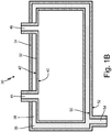
- FIG. 1B is a cross-sectional view of pressure vessel 30.
- Pressure vessel 30 includes inner container 32, outer container 34, barrier space 36, and captive fluid 38 (shown in FIG. 1B ).
- Inner container 32 includes inner surface 40, outer surface 42, inlet 44, and outlet 46.
- Outer container 34 includes inner surface 50, outer surface 52, and fluid port 54.
- Pressure vessel 30 is a double-walled pressure vessel that has inner container 32 positioned within outer container 34.
- Inner container 32 is a first container and outer container 34 is a second container.
- Barrier space 36 is formed between inner container 32 and outer container 34.
- Barrier space 36 contains captive fluid 38 between inner container 32 and outer container 34.
- Inner container 32 includes inner surface 40 and outer surface 42.
- Inner surface 40 forms an interior of inner container 32 and will come into contact with fluids in inner container 32.
- Outer surface 42 forms an exterior of inner container 32 and will come into contact with captive fluid 38 in barrier space 36.
- Outer surface 42 defines an interior boundary of barrier space 36.
- Inner container 32 further includes inlet 44 and outlet 46 that form fluid openings for accessing an interior of inner container 32.
- a fluid can be delivered to inner container 32 through inlet 44 and can be expelled from inner container 32 through outlet 46.
- Inlet 44 and outlet 46 are shown as being on one side of inner container 32 in the embodiment shown in FIGS. 1A-1B , but can each be positioned on any side of inner container 32 in alternate embodiments.
- Outer container 34 includes inner surface 50 and outer surface 52.
- Inner surface 50 forms an interior of outer container 34 and will come into contact with captive fluid 38 in barrier space 36.
- Inner surface 50 defines an exterior boundary of barrier space 36.
- Outer surface 52 forms an exterior of outer container 34 and will come into contact with an exterior environment surrounding pressure vessel 30.
- Outer container 34 further includes fluid port 54 that forms a point for accessing barrier space 36.
- Captive fluid 38 can be delivered to and evacuated from barrier space 36 through fluid port 54.
- Fluid port 54 is shown as being on a bottom side of outer container 34 in the embodiment shown in FIGS. 1A-1B , but can be positioned on any side of outer container 34 in alternate embodiments.
- Outer container 34 attaches to inner container 32 at inlet 44 and outlet 46.
- Inner container 32 and outer container 34 are integrally formed to create pressure vessel 30.
- Pressure vessel 30 can be made out of nickel alloys, ceramics, carbon alloys, or any other suitable material. Integrally manufacturing pressure vessel 30 reduces manufacturing time and creates fewer possible leak paths in finished pressure vessel 30 by minimizing welding, brazing, or other joining methods. Integral manufacturing also reduces the weight of pressure vessel 30. Integrally manufacturing pressure vessel 30 allows for many possible finished geometries of pressure vessel 30, for example tanks, pipes, and conformal shapes. Utilizing nickel alloys, ceramics, or carbon alloys also helps minimize the weight of pressure vessel 30. Nickel alloys, ceramics, or carbon alloys can also be chosen as proper materials for pressure vessel 30 depending on what pressure vessel 30 is being used for, what fluid is being stored in pressure vessel 30, and the space pressure vessel 30 needs for its finished volume.
- Inner container 32 and outer container 34 are integrally formed. Integrally forming pressure vessel 30 decreases manufacturing time and lowers possible leak paths through joints because there are fewer joining methods necessary for manufacturing. Integral formation also lowers the weight and size of vessel 30.
- Pressure vessel 30 has a double-walled construction and is designed to hold a fluid within inner container 32.
- Outer container 34 creates a second barrier between inner container 32 and an exterior environment. The fluid enters inner container 32 through inlet 44 and exits inner container 32 through outlet 46. If the fluid in inner container 32 leaks through inner container 32, it will be caught in barrier space 36 instead of leaking into the exterior environment surrounding pressure vessel 30.
- Captive fluid 38 can be a fluid with a high heat transfer coefficient, such as a pressurized inert gas (for example pressurized nitrogen or pressurized helium), a thermal oil, a liquid metal (for example liquid sodium, liquid sodium-potassium, liquid lead-bismuth, or liquid nickel), a molten salt (for example molten sodium-potassium carbonates or molten sodium-potassium fluorides), or combinations thereof.
- Captive fluid 38 improves the heat transfer capabilities of pressure vessel 30.
- heat from the fluid in inner container 32 can be transferred through inner container 32, captive fluid 38, outer container 34, and into an exterior environment surrounding pressure vessel 30 to cool the fluid in pressure vessel 30.
- pressure vessel 30 can include multiple inner containers 32 and outer containers 34 that can be positioned next to one another and heat from a fluid in a first pressure vessel can be transferred to fluid in a second pressure vessel.
- Captive fluid 38 can be delivered to and removed from barrier space 36 through fluid port 54.
- Fluid port 54 can be an opening, a duct, a pipe, or any other suitable port in outer container 34. If fluid from inner container 32 leaks into barrier space 36, the leaked fluid and captive fluid 38 can be removed from barrier space 36 through fluid port 54.
- Double-walled pressure vessel 30 is designed to hold a fluid within inner container 32 and efficiently exchange heat with an exterior environment.
- Outer container 34 acts as breach protection to keep leaked fluid within pressure vessel 30.
- the fluid enters pressure vessel 30 through inlet 44 and exits pressure vessel 30 through outlet 46.
- Fluid port 54 allows for easy removal of the leaked storage fluid from vessel 30. Should inner container 32 break, the fluid will be trapped within barrier space 36 until its removal through fluid port 54.
- Fluid port 54 also acts as an inlet and an outlet to charge and discharge captive fluid 38 into barrier space 36.
- Captive fluid 38 acts as a conductor to improve heat transfer between outer container 34 and inner container 32.
- FIG. 2 is a cross-sectional view of pressure vessel 30 with relief valve 60 and pressure sensor 62 attached to fluid port 54.
- Pressure vessel 30 includes inner container 32, outer container 34, barrier space 36, and captive fluid 38.
- Inner container 32 includes inner surface 40, outer surface 42, inlet 44, and outlet 46.
- Outer container 34 includes inner surface 50, outer surface 52, and fluid port 54.
- Pressure vessel 30 also includes relief valve 60 and pressure sensor 62.
- Pressure vessel 30 is a double-walled pressure vessel that has inner container 32 positioned within outer container 34.
- Barrier space 36 is formed between inner container 32 and outer container 34.
- Barrier space 36 contains captive fluid 38 between inner container 32 and outer container 34.
- Inner container 32 includes inner surface 40 that defines an interior of inner container 32 and outer surface 42 that defines an exterior of inner container 32.
- Inner container 32 further includes inlet 44 and outlet 46 that form fluid ports for accessing the interior of inner container 32.
- Outer container 34 includes inner surface 50 that defines an interior of outer container 34 and outer surface 52 that defines an exterior of outer container 34.
- Outer container 34 further includes fluid port 54 that forms a point for accessing barrier space 36.
- Captive fluid 38 can be delivered to and evacuated from barrier space 36 through fluid port 54.
- Captive fluid 38 can be a fluid with a high heat transfer coefficient, such as a pressurized inert gas (for example pressurized nitrogen or pressurized helium), a thermal oil, a liquid metal (for example liquid sodium, liquid sodium-potassium, liquid lead-bismuth, or liquid nickel), a molten salt (for example molten sodium-potassium carbonates or molten sodium-potassium fluorides), or combinations thereof.
- Fluid port 54 is in fluid connection with relief valve 60, as shown in FIG. 2 .
- Captive fluid 38 can flow through fluid port 54 to relief valve 60. If the pressure of captive fluid 38 exceeds a set threshold value, relief valve 60 can be opened to allow captive fluid 38 to flow out of barrier space 36.
- Captive fluid 38 can increase in pressure when the fluid in inner container 32 leaks through inner container 32 into barrier space 36. The increased pressure of captive fluid 38 with the leaked fluid will cause relief valve 60 to open to allow captive fluid 38 and the leaked fluid to be diverted through relief valve 60 to a suitable collection system. This prevents captive fluid 38 and the leaked fluid from leaking out of outer container 34 into an exterior environment.
- Relief valve 60 can include pressure sensor 62.
- Pressure sensor 62 can sense the pressure of captive fluid 38 at relief valve 60. Captive fluid 38 is charged into barrier space 36, fluid port 54, and relief valve 60 at a known pressure. Pressure sensor 62 is then set to a range surrounding the known charge pressure depending on the thermal expansion coefficients of captive fluid 38 and the material that pressure vessel 30 is made out of. Pressure sensor 62 continuously monitors the pressure of captive fluid 38. If inner container 32 breaches and captive fluid 38 moves into inner container 32 because inner container 32 is at a lower pressure than barrier space 36, then pressure sensor 62 will detect the pressure deviation from the expected value. Similarly, if inner container 32 breaches and the stored fluid moves into barrier space 36, then pressure sensor 62 will sense the change in pressure compared to the known charge value.
- pressure vessel 30 can include only relief valve 60 or only pressure sensor 62 at fluid port 54.
- Relief valve 60 and pressure sensor 62 allow for easy and quick detection of leaks in barrier space 36 when barrier space 36 is filled with a fluid having a high heat transfer coefficient. Detecting a leak from inner container 32 into barrier space 36 at relief valve 60 and pressure sensor 62 allows the leaked fluid to be removed from barrier space 36 before it leaks through outer container 34 and into an exterior environment surrounding pressure vessel 30.
- FIG. 3 is a cross-sectional view of the pressure vessel with an accumulator attached to the fluid port.
- Pressure vessel 30 includes inner container 32, outer container 34, barrier space 36, and captive fluid 38.
- Inner container 32 includes inner surface 40, outer surface 42, inlet 44, and outlet 46.
- Outer container 34 includes inner surface 50, outer surface 52, and fluid port 54.
- Pressure vessel 30 also includes accumulator 70 and position sensor 72.
- Pressure vessel 30 is a double-walled pressure vessel that has inner container 32 positioned within outer container 34.
- Barrier space 36 is formed between inner container 32 and outer container 34.
- Barrier space 36 contains captive fluid 38 between inner container 32 and outer container 34.
- Inner container 32 includes inner surface 40 that defines an interior of inner container 32 and outer surface 42 that defines an exterior of inner container 32.
- Inner container 32 further includes inlet 44 and outlet 46 that form fluid ports for accessing the interior of inner container 32.
- Outer container 34 includes inner surface 50 that defines an interior of outer container 34 and outer surface 52 that defines an exterior of outer container 34.
- Outer container 34 further includes fluid port 54 that forms a point for accessing barrier space 36.
- Captive fluid 38 can be delivered to and evacuated from barrier space 36 through fluid port 54.
- Captive fluid 38 is a fluid with a high heat transfer coefficient, such as a pressurized inert gas (for example pressurized nitrogen or pressurized helium), a thermal oil, a liquid metal (for example liquid sodium, liquid sodium-potassium, liquid lead-bismuth, or liquid nickel), a molten salt (for example molten sodium-potassium carbonates or molten sodium-potassium fluorides), or combinations thereof.
- Fluid port 54 is in fluid connection with accumulator 70, as shown in FIG. 3 . Captive fluid 38 can flow through fluid port 54 to accumulator 70. If the pressure of captive fluid 38 rises above a threshold value, some of captive fluid 38 can enter accumulator 70.
- Captive fluid 38 can increase in pressure when the fluid in inner container 32 leaks through inner container 32 into barrier space 36.
- Accumulator 70 can absorb the increased pressure of captive fluid 38 with the leaked fluid. This prevents captive fluid 38 and the leaked fluid from leaking out of outer container 34 into an exterior environment.
- Accumulator 70 can include position sensor 72.
- Position sensor 72 can be a linear variable displacement transformer. Position sensor 72 can sense the position of accumulator 70. Captive fluid 38 is charged into barrier space 36, fluid port 54, and accumulator 70 at a known volume dependent on the thermal expansion coefficient of captive fluid 38 and the material that pressure vessel 30 is made out of. Accumulator 70 is then set to a range of expected positions surrounding a position related to the known charge volume. Accumulator 70 can then continuously monitor the volume of captive fluid 38. If inner container 32 breaches and captive fluid moves into inner container 32 based on the differential pressure between inner container 32 and barrier space 36, then accumulator 70 and position sensor 72 will detect the breach because the position of accumulator 70 will deviate from the expected value.
- pressure vessel 30 can include only accumulator 70 or only position sensor 72 at fluid port 54.
- Accumulator 70 and position sensor 72 allow for easy and quick detection of leaks in barrier space 36 when barrier space 36 is filled with a fluid having a high heat transfer coefficient. Detecting a leak form inner container 32 into barrier space 36 at accumulator 70 and position sensor 72 allows the leaked fluid to be removed from barrier space 36 before it leaks through outer container 34 and into an exterior environment surrounding pressure vessel 30.
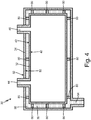
- FIG. 4 is a perspective view of pressure vessel 30 with heat transfer elements 80.
- Pressure vessel 30 includes inner container 32, outer container 34, barrier space 36, and captive fluid 38.
- Inner container 32 includes inner surface 40, outer surface 42, inlet 44, and outlet 46.
- Outer container 34 includes inner surface 50, outer surface 52, and fluid port 54.
- Pressure vessel 30 also includes heat transfer elements 80.
- Pressure vessel 30 is a double-walled pressure vessel that has inner container 32 positioned within outer container 34.
- Barrier space 36 is formed between inner container 32 and outer container 34.
- Barrier space 36 contains captive fluid 38 between inner container 32 and outer container 34.
- Inner container 32 includes inner surface 40 that defines an interior of inner container 32 and outer surface 42 that defines an exterior of inner container 32.
- Inner container 32 further includes inlet 44 and outlet 46 that form fluid ports for accessing the interior of inner container 32.
- Outer container 34 includes inner surface 50 that defines an interior of outer container 34 and outer surface 52 that defines an exterior of outer container 34.
- Outer container 34 further includes fluid port 54 that forms a point for accessing barrier space 36.
- Captive fluid 38 can be delivered to and evacuated from barrier space 36 through fluid port 54.
- Pressure vessel 30 also includes heat transfer elements 80.
- Heat transfer elements 80 extend from outer surface 42 of inner container 32 to inner surface 50 of outer container 34.
- Heat transfer elements 80 are integrally formed with pressure vessel 30.
- Heat transfer elements 80 can be shaped as pins, ribs, fins, or baffles. In alternate embodiments, heat transfer elements 80 can extend from outer surface 42 of inner container 32 into a center of barrier space 36 or from inner surface 50 of outer container 54 into a center of barrier space 36.
- Heat transfer elements 80 are integrally formed with pressure vessel 30.
- Pressure vessel 30 can include any number of heat transfer elements 80. Heat transfer elements 80 are positioned in pressure vessel 30 so that captive fluid 38 can move through barrier space 36 around heat transfer elements 80.
- Heat transfer elements 80 provide conductive pathways from inner container 32 to outer container 34 and an exterior environment surrounding pressure vessel 30.
- pressure vessels have a barrier space the acts as an insulator and prevents heat from efficiently transferring between the inner container and the outer container.
- Heat transfer elements 80 improve the heat transfer efficiency of pressure vessel 30 by providing pathways for heat to transfer between inner container 32 and outer container 34.
- Heat transfer elements 80 also act as structural elements for pressure vessel 30.
- Pressure vessel 30 can have any suitable shape and heat transfer elements 80 can be positioned in pressure vessel 30 to improve the structural strength of pressure vessel 30. Integrally forming inner container 32, outer container 34, and heat transfer elements 80 reduces the weight and lowers the manufacturing time of pressure vessel 30. Integrally forming pressure vessel 30 also reduces the areas in which pressure vessel 30 can develop breaks, as less welding, brazing, and/or other joining methods are used in manufacturing.
- Pressure vessel 30 can include any combinations of relief valve 60 (shown in FIG. 2 ), pressure sensor 62 (shown in FIG. 2 ), accumulator 70 (shown in FIG. 3 ), position sensor 72 (shown in FIG. 3 ), and heat transfer elements 80 (shown in FIG. 4 ).
- FIG. 5 is a cut-away perspective view of pressure vessel system 100 with first pressure vessel 102 and second pressure vessel 104 connected to central drain port 106.
- Pressure vessel system 100 includes first pressure vessel 102, second pressure vessel 104, and central drain port 106.
- First pressure vessel 102 includes inner container 110, outer container 112, and barrier space 114.
- Inner container 110 includes inner surface 120, outer surface 122, inlet 124, and outlet 126.
- Outer container 112 includes inner surface 130, outer surface 132, and fluid port 134.
- Second pressure vessel 104 includes inner container 140, outer container 142, and barrier space 144.
- Inner container 140 includes inner surface 150, outer surface 152, inlet 154, and outlet 156.
- Outer container 142 includes inner surface 160, outer surface 162, and fluid port 164.
- Pressure vessel system 100 includes first pressure vessel 102 and second pressure vessel 104 connected to one another and to central drain port 106.
- First pressure vessel 102 and second pressure vessel 104 run parallel to one another and are integrally formed with one another.
- Central drain port 106 is connected to first pressure vessel 102 and second pressure vessel 104 at a first end of first pressure vessel 102 and second pressure vessel 104.
- Central drain port 106 is integrally formed with first pressure vessel 102 and second pressure vessel 104.
- pressure vessel system 100 can have any number of pressure vessels that are integrally formed with one another and with central drain port 106.
- First pressure vessel 102 is shown as being a pipe in FIG.5 , but can have any suitable shape in alternate embodiments.
- First pressure vessel 102 includes inner container 110 positioned within outer container 112.
- Inner container 110 is a first container and outer container 112 is a second container.
- a first end and a second end of inner container 110 extend past outer container 112 in the embodiment shown in FIG. 5 .
- Barrier space 114 is formed between inner container 110 and outer container 112.
- Barrier space 114 is configured to contain a captive fluid (not shown in FIG. 5 ) between inner container 110 and outer container 112.
- Inner container 110 includes inner surface 120 that defines an interior of inner container 110 and outer surface 122 that defines an exterior of inner container 110.
- Inner container 110 further includes inlet 124 and outlet 126 that form fluid ports for accessing the interior of inner container 110.
- Outer container 112 includes inner surface 130 that defines an interior of outer container 112 and outer surface 132 that defines an exterior of outer container 112.
- Outer container 112 further includes fluid port 134 that forms a point for accessing barrier space 114.
- a captive fluid can be delivered to and evacuated from barrier space 114 through fluid port 134.
- First pressure vessel 102 has a double-walled construction and is designed to hold a fluid within inner container 110.
- Outer container 112 creates a second barrier between inner container 110 and an exterior environment.
- the fluid enters inner container 110 through inlet 124 and exits inner container 110 through outlet 126. If the fluid in inner container 110 leaks through inner container 110, it will be caught in barrier space 114 instead of leaking into the exterior environment surrounding first pressure vessel 102.
- Fluid port 134 can be used to remove the leaked fluid from first pressure vessel 102.
- Second pressure vessel 104 is shown as being a pipe in FIG.5 , but can have any suitable shape in alternate embodiments.
- Second pressure vessel 104 includes inner container 140 positioned within outer container 142.
- Inner container 140 is a first container and outer container 142 is a second container.
- a first end and a second end of inner container 140 extend past outer container 142 in the embodiment shown in FIG. 5 .
- Barrier space 144 is formed between inner container 140 and outer container 142.
- Barrier space 144 is configured to contain a captive fluid (not shown in FIG. 5 ) between inner container 140 and outer container 142.
- Inner container 140 includes inner surface 150 that defines an interior of inner container 140 and outer surface 152 that defines an exterior of inner container 140.
- Inner container 140 further includes inlet 154 and outlet 156 that form fluid ports for accessing the interior of inner container 140.
- Outer container 142 includes inner surface 160 that defines an interior of outer container 142 and outer surface 162 that defines an exterior of outer container 142.
- Outer container 142 further includes fluid port 164 that forms a point for accessing barrier space 144.
- a captive fluid can be delivered to and evacuated from barrier space 144 through fluid port 164.
- Second pressure vessel 104 has a double-walled construction and is designed to hold a fluid within inner container 140.
- Outer container 142 creates a second barrier between inner container 140 and an exterior environment.
- the fluid enters inner container 140 through inlet 154 and exits inner container 140 through outlet 156. If the fluid in inner container 140 leaks through inner container 140, it will be caught in barrier space 144 instead of leaking into the exterior environment surrounding second pressure vessel 104.
- Fluid port 164 can be used to remove the leaked fluid from second pressure vessel 104.
- Fluid port 134 of first pressure vessel 102 and fluid port 164 of second pressure vessel 104 are fluidly coupled to central drain port 106.
- Central drain port 106 includes an opening for delivering the captive fluid to and removing the captive fluid from central drain port 106.
- the captive fluid in central drain port 106 can be fluidly communicated to barrier space 114 of first pressure vessel 102 through fluid port 134 and to barrier space 144 of second pressure vessel 104 through fluid port 164.
- Pressure vessel system 100 can be used as a heat exchanger.
- a hot fluid can flow from inlet 124 to outlet 126 of inner container 110 of first pressure vessel 102, and a cold fluid can flow from inlet 154 to outlet 156 of inner container 140 of second pressure vessel 104.
- the hot fluid can be exhaust air and the cold fluid can be fuel. Heat from the exhaust fluid can be transferred through pressure vessel system 100 to warm the fuel in second pressure vessel 104.
- the hot fluid in first pressure vessel 102 and the cold fluid in second pressure vessel 104 are flowing in opposite directions.
- the hot fluid in first pressure vessel 102 and the cold fluid in second pressure vessel 104 can flow in the same direction.
- the hot fluid can flow through second pressure vessel 104 and the cold fluid can flow through first pressure vessel 102.
- the hot fluid and the cold fluid can be delivered to and stored in first pressure vessel 102 and second pressure vessel 104.
- Heat from the hot fluid in inner container 110 of first pressure vessel 102 can transfer through outer container 112, the captive fluid in barrier space 114, and outer container 112 of first pressure vessel 102 and then through outer container 142, the captive fluid in barrier space 144, and the inner container 140 of second pressure vessel 104 into the cold fluid in inner container 140 of second pressure vessel 104.
- the captive fluid in barrier space 114 of first pressure vessel 102 and in barrier space 144 of second pressure vessel 104 is an inert fluid with a high heat transfer coefficient, such as a pressurized inert gas (for example pressurized nitrogen or pressurized helium), a thermal oil, a liquid metal (for example liquid sodium, liquid sodium-potassium, liquid lead-bismuth, or liquid nickel), a molten salt (for example molten sodium-potassium carbonates or molten sodium-potassium fluorides), or combinations thereof.
- a pressurized inert gas for example pressurized nitrogen or pressurized helium
- a thermal oil for example liquid sodium, liquid sodium-potassium, liquid lead-bismuth, or liquid nickel
- a molten salt for example molten sodium-potassium carbonates or molten sodium-potassium fluorides
- Central drain port 106 fluidly couples barrier space 114 of first pressure vessel 102 and barrier space 144 of second pressure vessel 104.
- a leak detection mechanism (not shown in FIG. 5 ) can be attached to central drain port 106 to detect a leak in either first pressure vessel 102 or second pressure vessel 104.
- the leak detection mechanism can be a relief valve and/or pressure sensor as discussed in reference to FIG. 2 , an accumulator and/or a position sensor as discussed in reference to FIG. 3 , or any other mechanism that is suitable for detecting a leak in pressure vessel system 100. If a leak is detected by the leak detection mechanism, inlet 124 and/or outlet 126 of first pressure vessel 102 and/or inlet 144 and/or outlet 146 of second pressure vessel 104 can be closed.
- First pressure vessel 102 can also include heat transfer elements, such as the heat transfer elements shown in FIG. 4 , extending from inner container 110 to outer container 112.
- Second pressure vessel 104 can also include heat transfer elements, such as the heat transfer elements shown in FIG. 4 , extending from inner container 140 to outer container 142. Heat transfer elements can improve the heat transfer capabilities of pressure vessel system 100 and can improve the structural strength of pressure vessel system 100.
- Pressure vessel system 100 requires less space and weight than a series of separate pressure vessels, as a single leak detection mechanism can be used to detect leaks in both first pressure vessel 102 and second pressure vessel 104.
- Pressure vessel system 100 efficiently transfers heat between fluid in first pressure vessel 102 and fluid in second pressure vessel 104 using the captive fluid in barrier space 114 of first pressure vessel 102 and barrier space 144 of second pressure vessel 104.
- a pressure vessel includes a first container and a second container surrounding the first container and including a fluid port.
- the pressure vessel further includes a barrier space extending between the first container and the second container and a leak detection mechanism connected to the fluid port on the second container that is configured to detect a leak in the pressure vessel.
- the pressure vessel of the preceding paragraph can optionally include, additionally and/or alternatively, any one or more of the following features, configurations, and/or additional components:
- the barrier space contains a fluid with a high heat transfer coefficient.
- the fluid contained in the barrier space is selected from the group consisting of liquid nickel, liquid sodium-potassium, liquid sodium, liquid lead-bismuth, thermal oil, molten sodium-potassium carbonate, molten sodium-potassium fluoride, pressurized nitrogen, pressurized helium, and combinations thereof.
- the leak detection mechanism is a pressure sensor.
- the leak detection mechanism is a relief valve.
- the leak detection mechanism is a relief valve with a pressure sensor.
- the leak detection mechanism is an accumulator.
- the leak detection mechanism is an accumulator and a position sensor.
- the first container has a first inner surface and a first outer surface
- the second container has a second inner surface and a second outer surface
- the barrier space extends from the first outer surface to the second inner surface
- the pressure vessel further includes a heat transfer element within the barrier space extending from the first outer surface to the second inner surface.
- the first container, the second container, and the heat transfer element are integrally formed.
- the heat transfer element is selected from the group consisting of pins, ribs, baffles, fins, and combinations thereof.
- a pressure vessel system includes a first pressure vessel and a second pressure vessel.
- the first pressure vessel includes a first container, a second container surrounding the first container and including a fluid port, and a barrier space extending between the first container and the second container.
- the second pressure vessel includes a first container, a second container surrounding the first container and including a fluid port, and a barrier space extending between the first container and the second container.
- the pressure vessel system further includes a central drain port fluidly coupled to the fluid port of the first pressure vessel and the fluid port of the second pressure vessel.
- the pressure vessel system of the preceding paragraph can optionally include, additionally and/or alternatively, an one or more of the following features, configurations and/or additional components:
- the barrier space of the first pressure vessel, the barrier space of the second pressure vessel, and the central drain port contain a fluid having a high heat transfer coefficient.
- the fluid contained in the barrier space of the first pressure vessel, the barrier space of the second pressure vessel, and the central drain port is selected from the group consisting of liquid nickel, liquid sodium-potassium, liquid sodium, liquid lead-bismuth, thermal oil, molten sodium-potassium carbonate, molten sodium-potassium fluoride, pressurized nitrogen, pressurized helium, and combinations thereof.
- the central drain port is connected to a leak detection mechanism.
- the leak detection mechanism is a relief valve and a pressure sensor.
- the leak detection mechanism is an accumulator and a position sensor.
- the first pressure vessel further includes a heat transfer element within the barrier space extending from the first container to the second container.
- the second pressure vessel further includes a heat transfer element within the barrier space extending from the first container to the second container.
Landscapes
- Engineering & Computer Science (AREA)
- Physics & Mathematics (AREA)
- Thermal Sciences (AREA)
- Mechanical Engineering (AREA)
- General Engineering & Computer Science (AREA)
- General Physics & Mathematics (AREA)
- Filling Or Discharging Of Gas Storage Vessels (AREA)
Abstract
Description
- The present disclosure relates to double-walled pressure vessels, and in particular, to double-walled pressure vessels with heat exchange capabilities.
- Pressure vessels often hold hazardous fluids which could contaminate external environments or adjacent circuits if the fluids were to leak. Pressure vessels can be damaged over time by steady and cyclic loads due to temperature changes, vibration, pressure, and acceleration. Manufacturing or material defects, corrosion, and wear from fluid abrasion in high stress areas may also cause leaks to develop over time. A double-walled design is used to isolate leaks. A double-walled pressure vessel is created by placing a primary pressure vessel inside of a secondary pressure vessel with a barrier layer in-between. The barrier layer is an empty volume at the pressure of the exterior environment. The barrier layer isolates the leak so it can be safely drained and damage can be identified prior to any leak into an external environment or adjacent fluid circuit.
- Current double-walled pressure vessels are not ideal for applications that require maximum heat transfer between the interior and the exterior of the pressure vessel. The empty volume in the barrier layer acts as a thermal insulator.
- A pressure vessel includes a first container and a second container surrounding the first container and including a fluid port. The pressure vessel further includes a barrier space extending between the first container and the second container and a leak detection mechanism connected to the fluid port on the second container that is configured to detect a leak in the pressure vessel.
- A pressure vessel system includes a first pressure vessel and a second pressure vessel. The first pressure vessel includes a first container, a second container surrounding the first container and including a fluid port, and a barrier space extending between the first container and the second container. The second pressure vessel includes a first container, a second container surrounding the first container and including a fluid port, and a barrier space extending between the first container and the second container. The pressure vessel system further includes a central drain port fluidly coupled to the fluid port of the first pressure vessel and the fluid port of the second pressure vessel.
-
-
FIG. 1A is a perspective view of a pressure vessel with a barrier space and a fluid port. -
FIG. 1B is a cross-sectional view of the pressure vessel ofFIG. 1A . -
FIG. 2 is a cross-sectional view of the pressure vessel with a relief valve and a pressure sensor attached to the fluid port. -
FIG. 3 is a cross-sectional view of the pressure vessel with an accumulator attached to the fluid port. -
FIG. 4 is a perspective view of the pressure vessel with heat transfer elements. -
FIG. 5 is a cut-away perspective view of a pressure vessel system with a first pressure vessel and a second pressure vessel connected to a central drain port. -
FIG. 1A is a perspective view ofpressure vessel 30 withbarrier space 36 andfluid port 54.FIG. 1B is a cross-sectional view ofpressure vessel 30.Pressure vessel 30 includesinner container 32,outer container 34,barrier space 36, and captive fluid 38 (shown inFIG. 1B ).Inner container 32 includesinner surface 40,outer surface 42,inlet 44, andoutlet 46.Outer container 34 includesinner surface 50,outer surface 52, andfluid port 54. -
Pressure vessel 30 is a double-walled pressure vessel that hasinner container 32 positioned withinouter container 34.Inner container 32 is a first container andouter container 34 is a second container.Barrier space 36 is formed betweeninner container 32 andouter container 34.Barrier space 36 containscaptive fluid 38 betweeninner container 32 andouter container 34. -
Inner container 32 includesinner surface 40 andouter surface 42.Inner surface 40 forms an interior ofinner container 32 and will come into contact with fluids ininner container 32.Outer surface 42 forms an exterior ofinner container 32 and will come into contact withcaptive fluid 38 inbarrier space 36.Outer surface 42 defines an interior boundary ofbarrier space 36.Inner container 32 further includesinlet 44 andoutlet 46 that form fluid openings for accessing an interior ofinner container 32. A fluid can be delivered toinner container 32 throughinlet 44 and can be expelled frominner container 32 throughoutlet 46.Inlet 44 andoutlet 46 are shown as being on one side ofinner container 32 in the embodiment shown inFIGS. 1A-1B , but can each be positioned on any side ofinner container 32 in alternate embodiments. -
Outer container 34 includesinner surface 50 andouter surface 52.Inner surface 50 forms an interior ofouter container 34 and will come into contact withcaptive fluid 38 inbarrier space 36.Inner surface 50 defines an exterior boundary ofbarrier space 36.Outer surface 52 forms an exterior ofouter container 34 and will come into contact with an exterior environment surroundingpressure vessel 30.Outer container 34 further includesfluid port 54 that forms a point for accessingbarrier space 36.Captive fluid 38 can be delivered to and evacuated frombarrier space 36 throughfluid port 54.Fluid port 54 is shown as being on a bottom side ofouter container 34 in the embodiment shown inFIGS. 1A-1B , but can be positioned on any side ofouter container 34 in alternate embodiments. -
Outer container 34 attaches toinner container 32 atinlet 44 andoutlet 46.Inner container 32 andouter container 34 are integrally formed to createpressure vessel 30.Pressure vessel 30 can be made out of nickel alloys, ceramics, carbon alloys, or any other suitable material. Integrallymanufacturing pressure vessel 30 reduces manufacturing time and creates fewer possible leak paths in finishedpressure vessel 30 by minimizing welding, brazing, or other joining methods. Integral manufacturing also reduces the weight ofpressure vessel 30. Integrallymanufacturing pressure vessel 30 allows for many possible finished geometries ofpressure vessel 30, for example tanks, pipes, and conformal shapes. Utilizing nickel alloys, ceramics, or carbon alloys also helps minimize the weight ofpressure vessel 30. Nickel alloys, ceramics, or carbon alloys can also be chosen as proper materials forpressure vessel 30 depending on whatpressure vessel 30 is being used for, what fluid is being stored inpressure vessel 30, and thespace pressure vessel 30 needs for its finished volume. -
Inner container 32 andouter container 34 are integrally formed. Integrally formingpressure vessel 30 decreases manufacturing time and lowers possible leak paths through joints because there are fewer joining methods necessary for manufacturing. Integral formation also lowers the weight and size ofvessel 30. -
Pressure vessel 30 has a double-walled construction and is designed to hold a fluid withininner container 32.Outer container 34 creates a second barrier betweeninner container 32 and an exterior environment. The fluid entersinner container 32 throughinlet 44 and exitsinner container 32 throughoutlet 46. If the fluid ininner container 32 leaks throughinner container 32, it will be caught inbarrier space 36 instead of leaking into the exterior environment surroundingpressure vessel 30. -
Captive fluid 38 can be a fluid with a high heat transfer coefficient, such as a pressurized inert gas (for example pressurized nitrogen or pressurized helium), a thermal oil, a liquid metal (for example liquid sodium, liquid sodium-potassium, liquid lead-bismuth, or liquid nickel), a molten salt (for example molten sodium-potassium carbonates or molten sodium-potassium fluorides), or combinations thereof.Captive fluid 38 improves the heat transfer capabilities ofpressure vessel 30. In a first example, heat from the fluid ininner container 32 can be transferred throughinner container 32,captive fluid 38,outer container 34, and into an exterior environment surroundingpressure vessel 30 to cool the fluid inpressure vessel 30. In a second example, heat from an exterior environment surroundingpressure vessel 30 can be transferred throughouter container 34,captive fluid 38,inner container 32, and into the fluid ininner container 32 to warm the fluid inpressure vessel 30. In a third example,pressure vessel 30 can include multipleinner containers 32 andouter containers 34 that can be positioned next to one another and heat from a fluid in a first pressure vessel can be transferred to fluid in a second pressure vessel. -
Captive fluid 38 can be delivered to and removed frombarrier space 36 throughfluid port 54.Fluid port 54 can be an opening, a duct, a pipe, or any other suitable port inouter container 34. If fluid frominner container 32 leaks intobarrier space 36, the leaked fluid andcaptive fluid 38 can be removed frombarrier space 36 throughfluid port 54. - Double-
walled pressure vessel 30 is designed to hold a fluid withininner container 32 and efficiently exchange heat with an exterior environment.Outer container 34 acts as breach protection to keep leaked fluid withinpressure vessel 30. The fluid enterspressure vessel 30 throughinlet 44 and exitspressure vessel 30 throughoutlet 46.Fluid port 54 allows for easy removal of the leaked storage fluid fromvessel 30. Shouldinner container 32 break, the fluid will be trapped withinbarrier space 36 until its removal throughfluid port 54.Fluid port 54 also acts as an inlet and an outlet to charge and dischargecaptive fluid 38 intobarrier space 36.Captive fluid 38 acts as a conductor to improve heat transfer betweenouter container 34 andinner container 32. -
FIG. 2 is a cross-sectional view ofpressure vessel 30 withrelief valve 60 andpressure sensor 62 attached tofluid port 54.Pressure vessel 30 includesinner container 32,outer container 34,barrier space 36, andcaptive fluid 38.Inner container 32 includesinner surface 40,outer surface 42,inlet 44, andoutlet 46.Outer container 34 includesinner surface 50,outer surface 52, andfluid port 54.Pressure vessel 30 also includesrelief valve 60 andpressure sensor 62. -
Pressure vessel 30 is a double-walled pressure vessel that hasinner container 32 positioned withinouter container 34.Barrier space 36 is formed betweeninner container 32 andouter container 34.Barrier space 36 containscaptive fluid 38 betweeninner container 32 andouter container 34.Inner container 32 includesinner surface 40 that defines an interior ofinner container 32 andouter surface 42 that defines an exterior ofinner container 32.Inner container 32 further includesinlet 44 andoutlet 46 that form fluid ports for accessing the interior ofinner container 32.Outer container 34 includesinner surface 50 that defines an interior ofouter container 34 andouter surface 52 that defines an exterior ofouter container 34.Outer container 34 further includesfluid port 54 that forms a point for accessingbarrier space 36.Captive fluid 38 can be delivered to and evacuated frombarrier space 36 throughfluid port 54. -
Captive fluid 38 can be a fluid with a high heat transfer coefficient, such as a pressurized inert gas (for example pressurized nitrogen or pressurized helium), a thermal oil, a liquid metal (for example liquid sodium, liquid sodium-potassium, liquid lead-bismuth, or liquid nickel), a molten salt (for example molten sodium-potassium carbonates or molten sodium-potassium fluorides), or combinations thereof.Fluid port 54 is in fluid connection withrelief valve 60, as shown inFIG. 2 .Captive fluid 38 can flow throughfluid port 54 torelief valve 60. If the pressure ofcaptive fluid 38 exceeds a set threshold value,relief valve 60 can be opened to allowcaptive fluid 38 to flow out ofbarrier space 36.Captive fluid 38 can increase in pressure when the fluid ininner container 32 leaks throughinner container 32 intobarrier space 36. The increased pressure ofcaptive fluid 38 with the leaked fluid will causerelief valve 60 to open to allowcaptive fluid 38 and the leaked fluid to be diverted throughrelief valve 60 to a suitable collection system. This preventscaptive fluid 38 and the leaked fluid from leaking out ofouter container 34 into an exterior environment. -
Relief valve 60 can includepressure sensor 62.Pressure sensor 62 can sense the pressure ofcaptive fluid 38 atrelief valve 60.Captive fluid 38 is charged intobarrier space 36,fluid port 54, andrelief valve 60 at a known pressure.Pressure sensor 62 is then set to a range surrounding the known charge pressure depending on the thermal expansion coefficients ofcaptive fluid 38 and the material thatpressure vessel 30 is made out of.Pressure sensor 62 continuously monitors the pressure ofcaptive fluid 38. Ifinner container 32 breaches andcaptive fluid 38 moves intoinner container 32 becauseinner container 32 is at a lower pressure thanbarrier space 36, thenpressure sensor 62 will detect the pressure deviation from the expected value. Similarly, ifinner container 32 breaches and the stored fluid moves intobarrier space 36, thenpressure sensor 62 will sense the change in pressure compared to the known charge value. Ifouter container 34 were to breach, thenpressure sensor 62 would detect the change in pressure from the known charge value. Whenpressure sensor 62 senses a change in pressure from the known charge value,relief valve 60 can be opened to removecaptive fluid 38 and the leaked fluid frombarrier space 36,inlet 44 ofinner container 32 can be closed to prevent more fluid from being delivered toinner container 32, and/oroutlet 46 ofinner container 32 can be closed to prevent the fluid ininner container 32 from being removed frominner container 32. In alternate embodiments,pressure vessel 30 can includeonly relief valve 60 or onlypressure sensor 62 atfluid port 54. -
Relief valve 60 andpressure sensor 62 allow for easy and quick detection of leaks inbarrier space 36 whenbarrier space 36 is filled with a fluid having a high heat transfer coefficient. Detecting a leak frominner container 32 intobarrier space 36 atrelief valve 60 andpressure sensor 62 allows the leaked fluid to be removed frombarrier space 36 before it leaks throughouter container 34 and into an exterior environment surroundingpressure vessel 30. -
FIG. 3 is a cross-sectional view of the pressure vessel with an accumulator attached to the fluid port.Pressure vessel 30 includesinner container 32,outer container 34,barrier space 36, andcaptive fluid 38.Inner container 32 includesinner surface 40,outer surface 42,inlet 44, andoutlet 46.Outer container 34 includesinner surface 50,outer surface 52, andfluid port 54.Pressure vessel 30 also includesaccumulator 70 andposition sensor 72. -
Pressure vessel 30 is a double-walled pressure vessel that hasinner container 32 positioned withinouter container 34.Barrier space 36 is formed betweeninner container 32 andouter container 34.Barrier space 36 containscaptive fluid 38 betweeninner container 32 andouter container 34.Inner container 32 includesinner surface 40 that defines an interior ofinner container 32 andouter surface 42 that defines an exterior ofinner container 32.Inner container 32 further includesinlet 44 andoutlet 46 that form fluid ports for accessing the interior ofinner container 32.Outer container 34 includesinner surface 50 that defines an interior ofouter container 34 andouter surface 52 that defines an exterior ofouter container 34.Outer container 34 further includesfluid port 54 that forms a point for accessingbarrier space 36.Captive fluid 38 can be delivered to and evacuated frombarrier space 36 throughfluid port 54. -
Captive fluid 38 is a fluid with a high heat transfer coefficient, such as a pressurized inert gas (for example pressurized nitrogen or pressurized helium), a thermal oil, a liquid metal (for example liquid sodium, liquid sodium-potassium, liquid lead-bismuth, or liquid nickel), a molten salt (for example molten sodium-potassium carbonates or molten sodium-potassium fluorides), or combinations thereof..Fluid port 54 is in fluid connection withaccumulator 70, as shown inFIG. 3 .Captive fluid 38 can flow throughfluid port 54 toaccumulator 70. If the pressure ofcaptive fluid 38 rises above a threshold value, some ofcaptive fluid 38 can enteraccumulator 70.Captive fluid 38 can increase in pressure when the fluid ininner container 32 leaks throughinner container 32 intobarrier space 36.Accumulator 70 can absorb the increased pressure ofcaptive fluid 38 with the leaked fluid. This preventscaptive fluid 38 and the leaked fluid from leaking out ofouter container 34 into an exterior environment. -
Accumulator 70 can includeposition sensor 72.Position sensor 72 can be a linear variable displacement transformer.Position sensor 72 can sense the position ofaccumulator 70.Captive fluid 38 is charged intobarrier space 36,fluid port 54, andaccumulator 70 at a known volume dependent on the thermal expansion coefficient ofcaptive fluid 38 and the material thatpressure vessel 30 is made out of.Accumulator 70 is then set to a range of expected positions surrounding a position related to the known charge volume.Accumulator 70 can then continuously monitor the volume ofcaptive fluid 38. Ifinner container 32 breaches and captive fluid moves intoinner container 32 based on the differential pressure betweeninner container 32 andbarrier space 36, then accumulator 70 andposition sensor 72 will detect the breach because the position ofaccumulator 70 will deviate from the expected value. Similarly, ifinner container 32 breaches and the stored fluid moves intobarrier space 36,accumulator 70 andposition sensor 72 will sense the change in position ofaccumulator 70 compared to the known charge position. Ifouter container 34 were to breach, then accumulator 70 andposition sensor 72 would detect the deviation in position ofaccumulator 70 from the expected position that results from the breach. Whenposition sensor 72 senses a change in pressure from the known charge value,captive fluid 38 and the leaked fluid frombarrier space 36 can be removed frompressure vessel 30,inlet 44 ofinner container 32 can be closed to prevent more fluid from being delivered toinner container 32, and/oroutlet 46 ofinner container 32 can be closed to prevent the fluid ininner container 32 from being removed frominner container 32. In alternate embodiments,pressure vessel 30 can includeonly accumulator 70 oronly position sensor 72 atfluid port 54. -
Accumulator 70 andposition sensor 72 allow for easy and quick detection of leaks inbarrier space 36 whenbarrier space 36 is filled with a fluid having a high heat transfer coefficient. Detecting a leak forminner container 32 intobarrier space 36 ataccumulator 70 andposition sensor 72 allows the leaked fluid to be removed frombarrier space 36 before it leaks throughouter container 34 and into an exterior environment surroundingpressure vessel 30. -
FIG. 4 is a perspective view ofpressure vessel 30 withheat transfer elements 80.Pressure vessel 30 includesinner container 32,outer container 34,barrier space 36, andcaptive fluid 38.Inner container 32 includesinner surface 40,outer surface 42,inlet 44, andoutlet 46.Outer container 34 includesinner surface 50,outer surface 52, andfluid port 54.Pressure vessel 30 also includesheat transfer elements 80. -
Pressure vessel 30 is a double-walled pressure vessel that hasinner container 32 positioned withinouter container 34.Barrier space 36 is formed betweeninner container 32 andouter container 34.Barrier space 36 containscaptive fluid 38 betweeninner container 32 andouter container 34.Inner container 32 includesinner surface 40 that defines an interior ofinner container 32 andouter surface 42 that defines an exterior ofinner container 32.Inner container 32 further includesinlet 44 andoutlet 46 that form fluid ports for accessing the interior ofinner container 32.Outer container 34 includesinner surface 50 that defines an interior ofouter container 34 andouter surface 52 that defines an exterior ofouter container 34.Outer container 34 further includesfluid port 54 that forms a point for accessingbarrier space 36.Captive fluid 38 can be delivered to and evacuated frombarrier space 36 throughfluid port 54. -
Pressure vessel 30 also includesheat transfer elements 80.Heat transfer elements 80 extend fromouter surface 42 ofinner container 32 toinner surface 50 ofouter container 34.Heat transfer elements 80 are integrally formed withpressure vessel 30.Heat transfer elements 80 can be shaped as pins, ribs, fins, or baffles. In alternate embodiments,heat transfer elements 80 can extend fromouter surface 42 ofinner container 32 into a center ofbarrier space 36 or frominner surface 50 ofouter container 54 into a center ofbarrier space 36.Heat transfer elements 80 are integrally formed withpressure vessel 30.Pressure vessel 30 can include any number ofheat transfer elements 80.Heat transfer elements 80 are positioned inpressure vessel 30 so thatcaptive fluid 38 can move throughbarrier space 36 aroundheat transfer elements 80. -
Heat transfer elements 80 provide conductive pathways frominner container 32 toouter container 34 and an exterior environment surroundingpressure vessel 30. Typically, pressure vessels have a barrier space the acts as an insulator and prevents heat from efficiently transferring between the inner container and the outer container.Heat transfer elements 80 improve the heat transfer efficiency ofpressure vessel 30 by providing pathways for heat to transfer betweeninner container 32 andouter container 34. -
Heat transfer elements 80 also act as structural elements forpressure vessel 30.Pressure vessel 30 can have any suitable shape andheat transfer elements 80 can be positioned inpressure vessel 30 to improve the structural strength ofpressure vessel 30. Integrally forminginner container 32,outer container 34, andheat transfer elements 80 reduces the weight and lowers the manufacturing time ofpressure vessel 30. Integrally formingpressure vessel 30 also reduces the areas in whichpressure vessel 30 can develop breaks, as less welding, brazing, and/or other joining methods are used in manufacturing. -
Pressure vessel 30 can include any combinations of relief valve 60 (shown inFIG. 2 ), pressure sensor 62 (shown inFIG. 2 ), accumulator 70 (shown inFIG. 3 ), position sensor 72 (shown inFIG. 3 ), and heat transfer elements 80 (shown inFIG. 4 ). -
FIG. 5 is a cut-away perspective view ofpressure vessel system 100 withfirst pressure vessel 102 andsecond pressure vessel 104 connected tocentral drain port 106.Pressure vessel system 100 includesfirst pressure vessel 102,second pressure vessel 104, andcentral drain port 106.First pressure vessel 102 includesinner container 110,outer container 112, andbarrier space 114.Inner container 110 includesinner surface 120,outer surface 122,inlet 124, andoutlet 126.Outer container 112 includesinner surface 130,outer surface 132, andfluid port 134.Second pressure vessel 104 includesinner container 140,outer container 142, andbarrier space 144.Inner container 140 includesinner surface 150,outer surface 152,inlet 154, andoutlet 156.Outer container 142 includesinner surface 160,outer surface 162, andfluid port 164. -
Pressure vessel system 100 includesfirst pressure vessel 102 andsecond pressure vessel 104 connected to one another and tocentral drain port 106.First pressure vessel 102 andsecond pressure vessel 104 run parallel to one another and are integrally formed with one another.Central drain port 106 is connected tofirst pressure vessel 102 andsecond pressure vessel 104 at a first end offirst pressure vessel 102 andsecond pressure vessel 104.Central drain port 106 is integrally formed withfirst pressure vessel 102 andsecond pressure vessel 104. In alternate embodiments,pressure vessel system 100 can have any number of pressure vessels that are integrally formed with one another and withcentral drain port 106. -
First pressure vessel 102 is shown as being a pipe inFIG.5 , but can have any suitable shape in alternate embodiments.First pressure vessel 102 includesinner container 110 positioned withinouter container 112.Inner container 110 is a first container andouter container 112 is a second container. A first end and a second end ofinner container 110 extend pastouter container 112 in the embodiment shown inFIG. 5 .Barrier space 114 is formed betweeninner container 110 andouter container 112.Barrier space 114 is configured to contain a captive fluid (not shown inFIG. 5 ) betweeninner container 110 andouter container 112.Inner container 110 includesinner surface 120 that defines an interior ofinner container 110 andouter surface 122 that defines an exterior ofinner container 110.Inner container 110 further includesinlet 124 andoutlet 126 that form fluid ports for accessing the interior ofinner container 110.Outer container 112 includesinner surface 130 that defines an interior ofouter container 112 andouter surface 132 that defines an exterior ofouter container 112.Outer container 112 further includesfluid port 134 that forms a point for accessingbarrier space 114. A captive fluid can be delivered to and evacuated frombarrier space 114 throughfluid port 134. -
First pressure vessel 102 has a double-walled construction and is designed to hold a fluid withininner container 110.Outer container 112 creates a second barrier betweeninner container 110 and an exterior environment. The fluid entersinner container 110 throughinlet 124 and exitsinner container 110 throughoutlet 126. If the fluid ininner container 110 leaks throughinner container 110, it will be caught inbarrier space 114 instead of leaking into the exterior environment surroundingfirst pressure vessel 102.Fluid port 134 can be used to remove the leaked fluid fromfirst pressure vessel 102. -
Second pressure vessel 104 is shown as being a pipe inFIG.5 , but can have any suitable shape in alternate embodiments.Second pressure vessel 104 includesinner container 140 positioned withinouter container 142.Inner container 140 is a first container andouter container 142 is a second container. A first end and a second end ofinner container 140 extend pastouter container 142 in the embodiment shown inFIG. 5 .Barrier space 144 is formed betweeninner container 140 andouter container 142.Barrier space 144 is configured to contain a captive fluid (not shown inFIG. 5 ) betweeninner container 140 andouter container 142.Inner container 140 includesinner surface 150 that defines an interior ofinner container 140 andouter surface 152 that defines an exterior ofinner container 140.Inner container 140 further includesinlet 154 andoutlet 156 that form fluid ports for accessing the interior ofinner container 140.Outer container 142 includesinner surface 160 that defines an interior ofouter container 142 andouter surface 162 that defines an exterior ofouter container 142.Outer container 142 further includesfluid port 164 that forms a point for accessingbarrier space 144. A captive fluid can be delivered to and evacuated frombarrier space 144 throughfluid port 164. -
Second pressure vessel 104 has a double-walled construction and is designed to hold a fluid withininner container 140.Outer container 142 creates a second barrier betweeninner container 140 and an exterior environment. The fluid entersinner container 140 throughinlet 154 and exitsinner container 140 throughoutlet 156. If the fluid ininner container 140 leaks throughinner container 140, it will be caught inbarrier space 144 instead of leaking into the exterior environment surroundingsecond pressure vessel 104.Fluid port 164 can be used to remove the leaked fluid fromsecond pressure vessel 104. -
Fluid port 134 offirst pressure vessel 102 andfluid port 164 ofsecond pressure vessel 104 are fluidly coupled tocentral drain port 106.Central drain port 106 includes an opening for delivering the captive fluid to and removing the captive fluid fromcentral drain port 106. The captive fluid incentral drain port 106 can be fluidly communicated tobarrier space 114 offirst pressure vessel 102 throughfluid port 134 and tobarrier space 144 ofsecond pressure vessel 104 throughfluid port 164. -
Pressure vessel system 100 can be used as a heat exchanger. A hot fluid can flow frominlet 124 tooutlet 126 ofinner container 110 offirst pressure vessel 102, and a cold fluid can flow frominlet 154 tooutlet 156 ofinner container 140 ofsecond pressure vessel 104. For example, the hot fluid can be exhaust air and the cold fluid can be fuel. Heat from the exhaust fluid can be transferred throughpressure vessel system 100 to warm the fuel insecond pressure vessel 104. In the embodiment shown inFIG. 5 , the hot fluid infirst pressure vessel 102 and the cold fluid insecond pressure vessel 104 are flowing in opposite directions. In alternate embodiments, the hot fluid infirst pressure vessel 102 and the cold fluid insecond pressure vessel 104 can flow in the same direction. In further alternate embodiments, the hot fluid can flow throughsecond pressure vessel 104 and the cold fluid can flow throughfirst pressure vessel 102. Further, the hot fluid and the cold fluid can be delivered to and stored infirst pressure vessel 102 andsecond pressure vessel 104. - Heat from the hot fluid in
inner container 110 offirst pressure vessel 102 can transfer throughouter container 112, the captive fluid inbarrier space 114, andouter container 112 offirst pressure vessel 102 and then throughouter container 142, the captive fluid inbarrier space 144, and theinner container 140 ofsecond pressure vessel 104 into the cold fluid ininner container 140 ofsecond pressure vessel 104. The captive fluid inbarrier space 114 offirst pressure vessel 102 and inbarrier space 144 ofsecond pressure vessel 104 is an inert fluid with a high heat transfer coefficient, such as a pressurized inert gas (for example pressurized nitrogen or pressurized helium), a thermal oil, a liquid metal (for example liquid sodium, liquid sodium-potassium, liquid lead-bismuth, or liquid nickel), a molten salt (for example molten sodium-potassium carbonates or molten sodium-potassium fluorides), or combinations thereof.. The captive fluid increases the heat conduction betweenfirst pressure vessel 102 andsecond pressure vessel 104. -
Central drain port 106 fluidlycouples barrier space 114 offirst pressure vessel 102 andbarrier space 144 ofsecond pressure vessel 104. A leak detection mechanism (not shown inFIG. 5 ) can be attached tocentral drain port 106 to detect a leak in eitherfirst pressure vessel 102 orsecond pressure vessel 104. The leak detection mechanism can be a relief valve and/or pressure sensor as discussed in reference toFIG. 2 , an accumulator and/or a position sensor as discussed in reference toFIG. 3 , or any other mechanism that is suitable for detecting a leak inpressure vessel system 100. If a leak is detected by the leak detection mechanism,inlet 124 and/oroutlet 126 offirst pressure vessel 102 and/orinlet 144 and/or outlet 146 ofsecond pressure vessel 104 can be closed. -
First pressure vessel 102 can also include heat transfer elements, such as the heat transfer elements shown inFIG. 4 , extending frominner container 110 toouter container 112.Second pressure vessel 104 can also include heat transfer elements, such as the heat transfer elements shown inFIG. 4 , extending frominner container 140 toouter container 142. Heat transfer elements can improve the heat transfer capabilities ofpressure vessel system 100 and can improve the structural strength ofpressure vessel system 100. -
Pressure vessel system 100 requires less space and weight than a series of separate pressure vessels, as a single leak detection mechanism can be used to detect leaks in bothfirst pressure vessel 102 andsecond pressure vessel 104.Pressure vessel system 100 efficiently transfers heat between fluid infirst pressure vessel 102 and fluid insecond pressure vessel 104 using the captive fluid inbarrier space 114 offirst pressure vessel 102 andbarrier space 144 ofsecond pressure vessel 104. - The following are non-exclusive descriptions of possible embodiments of the present invention.
- A pressure vessel includes a first container and a second container surrounding the first container and including a fluid port. The pressure vessel further includes a barrier space extending between the first container and the second container and a leak detection mechanism connected to the fluid port on the second container that is configured to detect a leak in the pressure vessel.
- The pressure vessel of the preceding paragraph can optionally include, additionally and/or alternatively, any one or more of the following features, configurations, and/or additional components:
- The barrier space contains a fluid with a high heat transfer coefficient.
- The fluid contained in the barrier space is selected from the group consisting of liquid nickel, liquid sodium-potassium, liquid sodium, liquid lead-bismuth, thermal oil, molten sodium-potassium carbonate, molten sodium-potassium fluoride, pressurized nitrogen, pressurized helium, and combinations thereof.
- The leak detection mechanism is a pressure sensor.
- The leak detection mechanism is a relief valve.
- The leak detection mechanism is a relief valve with a pressure sensor.
- The leak detection mechanism is an accumulator.
- The leak detection mechanism is an accumulator and a position sensor.
- The first container has a first inner surface and a first outer surface, the second container has a second inner surface and a second outer surface, and the barrier space extends from the first outer surface to the second inner surface.
- The pressure vessel further includes a heat transfer element within the barrier space extending from the first outer surface to the second inner surface.
- The first container, the second container, and the heat transfer element are integrally formed.
- The heat transfer element is selected from the group consisting of pins, ribs, baffles, fins, and combinations thereof.
- A pressure vessel system includes a first pressure vessel and a second pressure vessel. The first pressure vessel includes a first container, a second container surrounding the first container and including a fluid port, and a barrier space extending between the first container and the second container. The second pressure vessel includes a first container, a second container surrounding the first container and including a fluid port, and a barrier space extending between the first container and the second container. The pressure vessel system further includes a central drain port fluidly coupled to the fluid port of the first pressure vessel and the fluid port of the second pressure vessel.
- The pressure vessel system of the preceding paragraph can optionally include, additionally and/or alternatively, an one or more of the following features, configurations and/or additional components:
- The barrier space of the first pressure vessel, the barrier space of the second pressure vessel, and the central drain port contain a fluid having a high heat transfer coefficient.
- The fluid contained in the barrier space of the first pressure vessel, the barrier space of the second pressure vessel, and the central drain port is selected from the group consisting of liquid nickel, liquid sodium-potassium, liquid sodium, liquid lead-bismuth, thermal oil, molten sodium-potassium carbonate, molten sodium-potassium fluoride, pressurized nitrogen, pressurized helium, and combinations thereof.
- The central drain port is connected to a leak detection mechanism.
- The leak detection mechanism is a relief valve and a pressure sensor.
- The leak detection mechanism is an accumulator and a position sensor.
- The first pressure vessel further includes a heat transfer element within the barrier space extending from the first container to the second container.
- The second pressure vessel further includes a heat transfer element within the barrier space extending from the first container to the second container.
- While the invention has been described with reference to an exemplary embodiment(s), it will be understood by those skilled in the art that various changes may be made and equivalents may be substituted for elements thereof without departing from the scope of the invention. In addition, many modifications may be made to adapt a particular situation or material to the teachings of the invention without departing from the essential scope thereof. Therefore, it is intended that the invention not be limited to the particular embodiment(s) disclosed, but that the invention will include all embodiments falling within the scope of the appended claims.
Claims (15)
- A pressure vessel (30) comprising:a first container (32);a second container (34) surrounding the first container and including a fluid port;a barrier space (36) extending between the first container and the second container; anda leak detection mechanism connected to the fluid port on the second container that is configured to detect a leak in the pressure vessel.
- The pressure vessel of claim 1, wherein the barrier space contains a fluid with a high heat transfer coefficient, and optionally wherein the fluid contained in the barrier space is selected from the group consisting of liquid nickel, liquid sodium-potassium, liquid sodium, liquid lead-bismuth, thermal oil, molten sodium-potassium carbonate, molten sodium-potassium fluoride, pressurized nitrogen, pressurized helium, and combinations thereof.
- The pressure vessel of claim 1 or 2, wherein the leak detection mechanism is a pressure sensor, or wherein the leak detection mechanism is a relief valve.
- The pressure vessel of claim 1 or 2, wherein the leak detection mechanism is a relief valve with a pressure sensor.
- The pressure vessel of claim 1 or 2, wherein the leak detection mechanism is an accumulator, or wherein the leak detection mechanism is an accumulator and a position sensor.
- The pressure vessel of any preceding claim, wherein:the first container has a first inner surface and a first outer surface;the second container has a second inner surface and a second outer surface; andthe barrier space extends from the first outer surface to the second inner surface.
- The pressure vessel of claim 6, and further comprising:
a heat transfer element within the barrier space extending from the first outer surface to the second inner surface. - The pressure vessel of claim 7, wherein the first container, the second container, and the heat transfer element are integrally formed, and/or wherein the heat transfer element is selected from the group consisting of a pin, a rib, a baffle, a fin, and combinations thereof.
- A pressure vessel system comprising:a first pressure vessel (30) comprising:a first container (32);a second container (34)surrounding the first container and including a fluid port; anda barrier space (36) extending between the first container and the second container;a second pressure vessel comprising:a first container;a second container surrounding the first container and including a fluid port; anda barrier space extending between the first container and the second container; anda central drain port fluidly coupled to the fluid port of the first pressure vessel and the fluid port of the second pressure vessel.
- The pressure vessel system of claim 9, wherein the barrier space of the first pressure vessel, the barrier space of the second pressure vessel, and the central drain port contain a fluid having a high heat transfer coefficient.
- The pressure vessel system of claim 9 or 10, wherein the fluid contained in the barrier space of the first pressure vessel, the barrier space of the second pressure vessel, and the central drain port is selected from the group consisting of liquid nickel, liquid sodium-potassium, liquid sodium, liquid lead-bismuth, thermal oil, molten sodium-potassium carbonate, molten sodium-potassium fluoride, pressurized nitrogen, pressurized helium, and combinations thereof.
- The pressure vessel system of any of claims 9 to 11, wherein the central drain port is connected to a leak detection mechanism.
- The pressure vessel system of claim 12, wherein the leak detection mechanism is a relief valve and a pressure sensor, or wherein the leak detection mechanism is an accumulator and a position sensor.
- The pressure vessel system of any of claims 9 to 13, wherein the first pressure vessel further comprises:
a heat transfer element within the barrier space extending from the first container to the second container. - The pressure vessel system of any of claims 9 to 14, wherein the second pressure vessel further comprises:
a heat transfer element within the barrier space extending from the first container to the second container.
Applications Claiming Priority (1)
| Application Number | Priority Date | Filing Date | Title |
|---|---|---|---|
| US16/593,660 US11320206B2 (en) | 2019-10-04 | 2019-10-04 | Pressure vessel with barrier layer |
Publications (1)
| Publication Number | Publication Date |
|---|---|
| EP3800458A1 true EP3800458A1 (en) | 2021-04-07 |
Family
ID=68771530
Family Applications (1)
| Application Number | Title | Priority Date | Filing Date |
|---|---|---|---|
| EP19213575.4A Withdrawn EP3800458A1 (en) | 2019-10-04 | 2019-12-04 | Pressure vessel with barrier layer |
Country Status (2)
| Country | Link |
|---|---|
| US (2) | US11320206B2 (en) |
| EP (1) | EP3800458A1 (en) |
Families Citing this family (2)
| Publication number | Priority date | Publication date | Assignee | Title |
|---|---|---|---|---|
| CN107331787B (en) * | 2017-06-26 | 2019-06-21 | 京东方科技集团股份有限公司 | Encapsulation cover plate, organic light emitting display and preparation method thereof |
| US12199259B1 (en) * | 2021-07-14 | 2025-01-14 | Nier Engineering, LLC | Housing as added outer layers with medium circulation |
Citations (6)
| Publication number | Priority date | Publication date | Assignee | Title |
|---|---|---|---|---|
| JPS63120286A (en) * | 1986-11-07 | 1988-05-24 | 石川島播磨重工業株式会社 | Double tank fast breeder reactor |
| US5668534A (en) * | 1992-12-11 | 1997-09-16 | Eastman Kodak Company | Containment failure detection device and method |
| DE10062089C1 (en) * | 2000-12-13 | 2001-12-13 | Sicherungsgeraetebau Gmbh | Leakage display device for double-walled storage container or double-walled pipeline monitors pressure in monitoring space between inner and outer walls |
| KR20040011763A (en) * | 2002-07-30 | 2004-02-11 | 주식회사 동명엔터프라이즈 | Apparatus for sensing and alarming leakage or overflow of liquid material contained in a tank |
| US20090113995A1 (en) * | 2007-05-02 | 2009-05-07 | Golding Randy D | Method and apparatus for leak detection |
| KR20160091933A (en) * | 2013-11-29 | 2016-08-03 | 가즈트랑스포르 에 떼끄니가즈 | Monitoring of a sealed and thermally insulated vat |
Family Cites Families (27)
| Publication number | Priority date | Publication date | Assignee | Title |
|---|---|---|---|---|
| GB1130830A (en) | 1966-02-25 | 1968-10-16 | Atomic Energy Authority Uk | Improvements relating to heat exchangers |
| US4249593A (en) | 1979-01-19 | 1981-02-10 | The United States Of America As Represented By The United States Department Of Energy | Heat exchanger with leak detecting double wall tubes |
| US4237968A (en) | 1979-05-02 | 1980-12-09 | Westinghouse Electric Corp. | Heat exchanger with double wall tubes and three tube sheets |
| US4410109A (en) * | 1982-05-04 | 1983-10-18 | Quality Engineering Co., Inc. | Leak detection system and check valve for use therein |
| US4767593A (en) | 1987-06-15 | 1988-08-30 | Wedellsborg Bendt W | Multiple shell pressure vessel |
| US5048597A (en) | 1989-12-18 | 1991-09-17 | Rockwell International Corporation | Leak-safe hydrogen/air heat exchanger in an ACE system |
| JP3549883B2 (en) * | 1992-10-01 | 2004-08-04 | アメリカン ステリライザー カンパニー | Liquid dispensing system and dispensing method based on accumulator |
| US5630470A (en) | 1995-04-14 | 1997-05-20 | Sonic Environmental Systems, Inc. | Ceramic heat exchanger system |
| DE69530126T2 (en) | 1995-12-04 | 2003-12-11 | Toray Industries | PRESSURE TANKS AND METHOD FOR THE PRODUCTION THEREOF |
| ZA969583B (en) | 1995-12-14 | 1997-06-02 | Morton Int Inc | Fuel containment for fluid fueled airbag inflators |
| US5702026A (en) * | 1996-04-16 | 1997-12-30 | Convault, Inc. | Container with secondary containment venting by form of construction |
| US6631754B1 (en) | 2000-03-14 | 2003-10-14 | L'air Liquide Societe Anonyme A Directoire Et Conseil De Surveillance Pour L'etude Et L'exploitation Des Procedes Georges Claude | Regenerative heat exchanger and method for heating a gas therewith |
| US6513542B1 (en) * | 2000-08-08 | 2003-02-04 | Taiwan Semiconductor Manufacturing Co., Ltd | Liquid supply or drain pipe equipped with a leakage detector |
| DE10317197A1 (en) | 2003-04-15 | 2004-11-04 | Degussa Ag | Electrically heated reactor and method for carrying out gas reactions at high temperature using this reactor |
| US7063132B2 (en) | 2003-12-29 | 2006-06-20 | Bradford White Corporation | Multi-wall heat exchanger for a water heater |
| US7699188B2 (en) | 2004-04-23 | 2010-04-20 | Amtrol Licensing Inc. | Hybrid pressure vessel with separable jacket |
| US7938171B2 (en) | 2006-12-19 | 2011-05-10 | United Technologies Corporation | Vapor cooled heat exchanger |
| SE533287C2 (en) | 2008-04-18 | 2010-08-10 | Sapa Heat Transfer Ab | Sandwich material for soldering with high strength at high temperature |
| US20100314081A1 (en) * | 2009-06-12 | 2010-12-16 | Reis Bradley E | High Temperature Graphite Heat Exchanger |
| CA2702463C (en) | 2010-04-26 | 2013-07-09 | Huazi Lin | Heat driven self-circulating fluid heating and storage tank and system |
| CA2803979C (en) | 2010-06-29 | 2018-04-03 | H2Safe, Llc | Fluid container |
| JP5597122B2 (en) * | 2010-12-20 | 2014-10-01 | 株式会社日立製作所 | Reverse osmosis processing equipment |
| IN2014CN04603A (en) * | 2011-12-22 | 2015-09-18 | Tetra Laval Holdings & Finance | |
| JP2014010085A (en) | 2012-06-29 | 2014-01-20 | Tokyo Rigaku Kensa Kk | Leakage inspection method for heat exchanger tube |
| US9921126B2 (en) * | 2015-08-31 | 2018-03-20 | Advanced Test Concepts, Llc | Large volume test apparatuses and methods for detection of small defects |
| CA2955613A1 (en) | 2016-01-28 | 2017-07-28 | Rolls-Royce North American Technologies, Inc. | Heat exchanger integrated with fuel nozzle |
| US10748783B2 (en) * | 2018-07-25 | 2020-08-18 | Applied Materials, Inc. | Gas delivery module |
-
2019
- 2019-10-04 US US16/593,660 patent/US11320206B2/en active Active
- 2019-12-04 EP EP19213575.4A patent/EP3800458A1/en not_active Withdrawn
-
2022
- 2022-05-02 US US17/734,176 patent/US11879692B2/en active Active
Patent Citations (6)
| Publication number | Priority date | Publication date | Assignee | Title |
|---|---|---|---|---|
| JPS63120286A (en) * | 1986-11-07 | 1988-05-24 | 石川島播磨重工業株式会社 | Double tank fast breeder reactor |
| US5668534A (en) * | 1992-12-11 | 1997-09-16 | Eastman Kodak Company | Containment failure detection device and method |
| DE10062089C1 (en) * | 2000-12-13 | 2001-12-13 | Sicherungsgeraetebau Gmbh | Leakage display device for double-walled storage container or double-walled pipeline monitors pressure in monitoring space between inner and outer walls |
| KR20040011763A (en) * | 2002-07-30 | 2004-02-11 | 주식회사 동명엔터프라이즈 | Apparatus for sensing and alarming leakage or overflow of liquid material contained in a tank |
| US20090113995A1 (en) * | 2007-05-02 | 2009-05-07 | Golding Randy D | Method and apparatus for leak detection |
| KR20160091933A (en) * | 2013-11-29 | 2016-08-03 | 가즈트랑스포르 에 떼끄니가즈 | Monitoring of a sealed and thermally insulated vat |
Also Published As
| Publication number | Publication date |
|---|---|
| US20220260318A1 (en) | 2022-08-18 |
| US11879692B2 (en) | 2024-01-23 |
| US11320206B2 (en) | 2022-05-03 |
| US20210102757A1 (en) | 2021-04-08 |
Similar Documents
| Publication | Publication Date | Title |
|---|---|---|
| US11879692B2 (en) | Pressure vessel with barrier layer | |
| US4372374A (en) | Vented heat transfer tube assembly | |
| EP2244046A2 (en) | Plate fin heat exchanger | |
| US20180292137A1 (en) | Heat exchangers | |
| US4210199A (en) | Heat exchange system | |
| US20100291419A1 (en) | Battery pack heat exchanger, systems, and methods | |
| US9786395B2 (en) | Air-cooled heat exchanger and system and method of using the same to remove waste thermal energy from radioactive materials | |
| EP3789718A1 (en) | Heat exchanger with build powder in barrier channels | |
| US20140352934A1 (en) | Plate heat exchanger | |
| JP2019109039A (en) | Integrated heat exchanger | |
| CN108955305B (en) | Liquid heavy metal shell and tube heat exchanger | |
| GB2082312A (en) | Header tank construction | |
| EP2348271A1 (en) | Ebullient cooling apparatus | |
| US20200300551A1 (en) | Heat exchanger temperature change rate control | |
| EP3625510B1 (en) | Double wall printed circuit heat exchanger | |
| KR101540668B1 (en) | Passive safety system and nuclear power plant having the same | |
| CN112639386B (en) | heat exchanger | |
| CN109099752A (en) | Heat exchanger and collector for heat exchanger | |
| EP2322890A1 (en) | A marine heat exchanger | |
| EP3854588B1 (en) | Pressure vessel with barrier passage containing fire suppressant elements | |
| JP6659215B2 (en) | Heat exchanger | |
| EP4635839A1 (en) | Insulating system for liquefied gas storage tank, and ship comprising same | |
| EP4067805B1 (en) | Heat exchanger and refrigeration system | |
| EP4498029A1 (en) | Plate heat exchanger with improved fluid leakage detection system | |
| EP3680594B1 (en) | Brazed fluid connection for a heat exchanger |
Legal Events
| Date | Code | Title | Description |
|---|---|---|---|
| PUAI | Public reference made under article 153(3) epc to a published international application that has entered the european phase |
Free format text: ORIGINAL CODE: 0009012 |
|
| STAA | Information on the status of an ep patent application or granted ep patent |
Free format text: STATUS: THE APPLICATION HAS BEEN PUBLISHED |
|
| AK | Designated contracting states |
Kind code of ref document: A1 Designated state(s): AL AT BE BG CH CY CZ DE DK EE ES FI FR GB GR HR HU IE IS IT LI LT LU LV MC MK MT NL NO PL PT RO RS SE SI SK SM TR |
|
| AX | Request for extension of the european patent |
Extension state: BA ME |
|
| STAA | Information on the status of an ep patent application or granted ep patent |
Free format text: STATUS: REQUEST FOR EXAMINATION WAS MADE |
|
| 17P | Request for examination filed |
Effective date: 20211007 |
|
| RBV | Designated contracting states (corrected) |
Designated state(s): AL AT BE BG CH CY CZ DE DK EE ES FI FR GB GR HR HU IE IS IT LI LT LU LV MC MK MT NL NO PL PT RO RS SE SI SK SM TR |
|
| STAA | Information on the status of an ep patent application or granted ep patent |
Free format text: STATUS: EXAMINATION IS IN PROGRESS |
|
| 17Q | First examination report despatched |
Effective date: 20220624 |
|
| STAA | Information on the status of an ep patent application or granted ep patent |
Free format text: STATUS: THE APPLICATION HAS BEEN WITHDRAWN |
|
| 18W | Application withdrawn |
Effective date: 20240405 |