EP3800428A1 - Firearm with a magazine holder - Google Patents
Firearm with a magazine holder Download PDFInfo
- Publication number
- EP3800428A1 EP3800428A1 EP19201444.7A EP19201444A EP3800428A1 EP 3800428 A1 EP3800428 A1 EP 3800428A1 EP 19201444 A EP19201444 A EP 19201444A EP 3800428 A1 EP3800428 A1 EP 3800428A1
- Authority
- EP
- European Patent Office
- Prior art keywords
- actuating
- spring
- extension
- actuating element
- magazine
- Prior art date
- Legal status (The legal status is an assumption and is not a legal conclusion. Google has not performed a legal analysis and makes no representation as to the accuracy of the status listed.)
- Granted
Links
Images




Classifications
-
- F—MECHANICAL ENGINEERING; LIGHTING; HEATING; WEAPONS; BLASTING
- F41—WEAPONS
- F41A—FUNCTIONAL FEATURES OR DETAILS COMMON TO BOTH SMALLARMS AND ORDNANCE, e.g. CANNONS; MOUNTINGS FOR SMALLARMS OR ORDNANCE
- F41A3/00—Breech mechanisms, e.g. locks
- F41A3/64—Mounting of breech-blocks; Accessories for breech-blocks or breech-block mountings
- F41A3/72—Operating handles or levers; Mounting thereof in breech-blocks or bolts
-
- F—MECHANICAL ENGINEERING; LIGHTING; HEATING; WEAPONS; BLASTING
- F41—WEAPONS
- F41A—FUNCTIONAL FEATURES OR DETAILS COMMON TO BOTH SMALLARMS AND ORDNANCE, e.g. CANNONS; MOUNTINGS FOR SMALLARMS OR ORDNANCE
- F41A17/00—Safety arrangements, e.g. safeties
- F41A17/34—Magazine safeties
- F41A17/38—Magazine mountings, e.g. for locking the magazine in the gun
-
- F—MECHANICAL ENGINEERING; LIGHTING; HEATING; WEAPONS; BLASTING
- F41—WEAPONS
- F41A—FUNCTIONAL FEATURES OR DETAILS COMMON TO BOTH SMALLARMS AND ORDNANCE, e.g. CANNONS; MOUNTINGS FOR SMALLARMS OR ORDNANCE
- F41A35/00—Accessories or details not otherwise provided for
- F41A35/06—Adaptation of guns to both right and left hand use
-
- F—MECHANICAL ENGINEERING; LIGHTING; HEATING; WEAPONS; BLASTING
- F41—WEAPONS
- F41A—FUNCTIONAL FEATURES OR DETAILS COMMON TO BOTH SMALLARMS AND ORDNANCE, e.g. CANNONS; MOUNTINGS FOR SMALLARMS OR ORDNANCE
- F41A9/00—Feeding or loading of ammunition; Magazines; Guiding means for the extracting of cartridges
- F41A9/01—Feeding of unbelted ammunition
- F41A9/24—Feeding of unbelted ammunition using a movable magazine or clip as feeding element
Definitions
- the invention relates to a firearm with a magazine holder for magazines which, according to the preamble of claim 1 and US 8,713,832 B2 , have a lateral locking element (recess/extension) on the magazine housing.
- the invention is preferably intended for rifles but in principle also for use in pistols.
- magazines are secured against a slipping out of the housing-the weapon-by a magazine holder which engages in the locking element of the magazine.
- a locking element can be, e.g., a catch, an extension, or preferably a recess (indentation or opening) on the outer shell of the magazine, in which a mating catch, extension, latch, or the like of the magazine holder engages/meshes.
- magazine holder is regarded equivalent to the also commonly known terms "magazine release” or "magazine lever”.
- a multiplicity of magazines has such locking elements on the side of the magazine housing, when the magazine is viewed in the inserted state relative to the weapon longitudinal axis or the weapon median plane.
- Most widely used are magazines that are compatible with rifles on the basis of assault rifles of the AR-15, M-16, M-4, or similar type.
- a recess is most commonly formed on the magazine housing, in which a movable latch of the magazine holder can engage.
- the magazine is released via a multi-piece, spring-loaded magazine holder, wherein an actuation, as seen in the barrel direction from the right, results in a deflection of the entire magazine holder to the left.
- the magazine catch (a term also frequently used in German), which is arranged on a holding arm in the inward direction toward the magazine, is deflected so far to the left that a release of the magazine takes place.
- a release button which is attached to the holding arm and supported by the housing, also allows for a deflection of the magazine catch to the left when actuated.
- US4645134A also discloses a multi-piece magazine holder with an internal spring. Upon actuation from the left, the magazine can be released in that the release is supported by the housing via a lever, resulting in a lateral deflection of the holding arm due to the rotary connection to the internally arranged holding arm.
- EP2823249B1 shall be mentioned, which, in a reverse arrangement, has a holding arm with a longitudinal slot, in which a handle is arranged for an actuation from the left.
- the support on the housing is provided via a bulge on the handle; as a result, the holding arm can be deflected laterally until the magazine is released.
- Such magazine holders operable on both sides are also widely used for pistols and have a multiplicity of components and more or less complicated gearing devices for a force transmission in case of a release movement from the "left".
- numerous magazine holders are known from the prior art, which require one or even more springs to return the magazine holder to its original position and/or to pretension the magazine catch.
- the individual elements require frequent maintenance, the magazine holder becomes error-prone and/or susceptible to contamination with increasing complexity.
- the problem of the security against loss for the individual elements is not consistently ensured for the magazine holders described. All known magazine holders additionally require one, occasionally even several tools for installation and/or maintenance. This is particularly problematic under harsh operating conditions.
- the present invention addresses the problem of providing a magazine holder which can be actuated on both sides of the weapon median plane, which overcomes the aforementioned disadvantages of the prior art, and has the lowest possible number of individual components.
- the invention addresses the problem of providing, at least in one embodiment, a magazine holder which can be assembled without tools and arranged securely against loss in the housing.
- a further problem addressed by a development of the invention is that the magazine holder requires a preferably even release force from both sides.
- the invention achieves that the magazine holder comprises only two interconnected actuating elements which, within boundaries, are pivotable to one another about an axis and separable from one another in an angular position by longitudinal shifting, and a spring.
- the two actuating elements are in the limit position of the pivoting, in which no shifting is possible.
- Figure 1 shows a perspective, schematic view of a weapon housing 5 in the area of the magazine 6.
- the weapon median plane 51 and the barrel direction 52 i.e., the direction of the bore axis, are also indicated.
- a magazine holder 1 according to the invention consisting of a first, left, actuating element 2, a second, right, actuating element 3, and a spring 4 is shown in the manner of an exploded view.
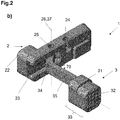
- Figures 2a and 2b show a perspective view of the two actuating elements 2, 3, in the relative position appropriate for assembly ( Figure 2a ) and after assembly ( Figure 2b ), respectively.
- the first, left, actuating element 2 has a generally elongated-solid shape with a first actuating extension 22, an undercut longitudinal guide 23 of a spring seat 24, and a bearing recess 25 which defines a bearing axis 26.
- the bearing recess 25 preferably consists of a through-bore.
- the second, right, actuating element 3 has a generally slim-curved shape with a second actuating extension 32 with a support thickening 31, which are formed on a first end section 33.
- a second end section 34 By means of a connecting section 35, a second end section 34, angled about an opening angle 70, is provided.
- circular cylindrical guide extensions 36 are formed normally to the plane of the actuating element 3 defined by the angulation, but said guide extensions have flattened portions approximately parallel ( Figure 4b ) to the alignment of the second end section 34. It has proved to be particularly advantageous if the opening angle 70 lies between 120° and 140°, preferably between 125° and 135°, and particularly preferably between 127.5° and 132.5°.
- the second end section 34 can be pushed into the undercut longitudinal guide 23, but is fixed in its angular position, Figure 3a . Only when the guide extensions 36 reach the area of the bearing recess 25 during insertion, Figure 3b , a rotation between the two parts can take place within boundaries.
- One boundary is practically given with the insertion position shown, since the second end section 34 cannot be rotated clockwise but bears against the bottom of the longitudinal guide. The other boundary is reached when, during a counterclockwise rotation, the end of the end section 34, best visible in Figure 4b , bears against the bottom of the longitudinal guide.
- the insertion angle 71 which can be slightly smaller than or equal to the opening angle 70, as well as the working angle 72, are also shown.
- the working angle 72 is plotted practically exactly at 90°.
- the other boundary is thus reached when an end stop is designed such that in the installation position, the working angle 72 lies between 85° and 95°, preferably between 87.5° and 92.5°, and particularly preferably is exactly 90°.
- the cross-sectional view clearly shows how the guide extensions 36 in the area of the bearing recess 25 are released in their angular position, so that the relative pivoting of the two actuating elements 2, 3 can take place.
- this design ensures that even after a slight pivoting from the position of Figure 3a , a shifting in the longitudinal guide 23 is no longer possible, and in this respect, the two parts are secured.
- Figure 4a shows a view similar to that of Figure 3b , but with a position of the cross-section in the area beyond the undercut, with the tip of the second end section 34 and its position in the longitudinal guide 23 thus becoming clearly visible.
- the aligning position of the two actuating extensions 22, 32 is also emphasized by the dotted center line, the actuating axis 27, and two sections are shown which correspond to the lever lengths 28 in case of actuation.
- Figure 4b schematically shows the second end section 34 and enlarged a particular embodiment with its angular relationships. It can be seen that the locking angle 74, formed between the stop 38 and the flattened portion of the guide extension 36, is smaller than the stop angle 73, formed between the stop 38 and the inner surface of the second end section 34.
- This particular angular relationship allows that the insertion of the second end section 34 in the undercut longitudinal guide 23 is made possible, and that, upon rotation to the working angle 72, a shift protection of the guide extension 36 is formed within the first actuating element 2, as becomes particularly clear from the comparison with Figure 3a and Figure 3b .
- the tip of the end section 34, which forms the stop 38, is also clearly visible. This stop 38 effectively prevents an unwanted "over-rotation" of the second actuating element in the installation position.
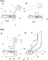
- Figures 5a,b show the situation in the installation state, the installation situation, without the magazine 6 as a top view and/or as a cross-section BB:
- the actuating extensions 22, 23 protrude over the outer contour of the weapon 5, the locking extension 21 protrudes into the magazine well 53, a spring 4 is inserted in the housing 5 and in the first actuating element 2 and pushes said first actuating element toward the weapon median plane 51.
- the cross-section of Figure 5b clearly shows the design and function of the thickening 31 of the second actuating element 3. Under the force of the spring 4, it pushes from the inside against the housing 5 and prevents any further outward movement of the second actuating element 3.
- Figures 6a,b show, in views corresponding to those of Figure 5a , the actuation of the magazine holder according to the invention:
- the two actuating elements 2, 3 are shifted, practically without changing their relative position, against the force of the spring 4, and the locking extension 21 is pushed to the side.
- Pressing on the first actuating extension 22 (from the left), Figure 6b results in the already described rotation of this element against the force of the spring 4 about the rotational axis 37, which also causes the locking extension 21 to be pushed to the side.
- Figure 7 shows the situation in the installation state without the magazine: the first actuating element is seated in the holder opening 54 ( Figure 1 ) and is held in this position by the spring 4.
- the second actuating element is pushed behind the magazine well 53 approximately normally to the weapon median plane through the weapon housing 5 and protrudes outwardly over its contour.
- the spring 4 is shown perspectively and, depending on the orientation, it must be regarded to be U-shaped or C-shaped and is inserted with its shorter spring element section 42 in a recess or groove of the housing 5, and with the other, longer spring elementsection 41, which terminates in a securing tip 43, it is inserted in the spring recess 24 of the first actuating element 2.
- This spring recess 24 is best shown in Figures 2a , b and 3 : It is a blind hole-like groove, which is undercut asymmetrically and in its end area, as can be seen particularly clearly in Figure 2b , it has both a widening of the opening of the groove as well as the undercut, and so the securing tip 43 can be threaded but is then held in place while under the spring effect. This is also clearly shown in Figure 2b .
- Figure 8b shows a variation of the spring; the spring recess 24 would have to be adapted accordingly, which presents no problems.
- the assembly can now be performed in a simple manner by assembling the first and second actuating element 2, 3 according to the aforementioned steps.
- the magazine holder 1 is subsequently inserted from the "left" into the housing 5 until the second actuating extension 32 protrudes from the housing on the opposite side. Due to the insertion into the housing 5, an unintentional rotation from the installation position is no longer possible.
- the magazine holder 1 is securely fastened against falling out with the spring 4 in the housing 5, and the locking extension 21 is simultaneously pretensioned in the direction of the weapon median plane 51.
- the guide extension(s) 36 is/are formed such that their height is greater than their radius.
- the second end section 34 can in this manner be easily inserted into the longitudinal guide 23 and by rotating within the bearing recess 25, it can be brought into the installation position, in which an accidental disassembly or shifting of the actuating elements toward one another is avoided.
- the shape of the spring 4 can be bow-shaped or leaf spring-shaped, wherein a first spring element section engages in the first actuating element and a second spring element section engages in the weapon housing.
- a selected lever length 28 as a distance between the spring recess 25 and bearing axis 26 is essentially equal to the distance between an actuating axis through the center of the first and second actuating extension 2, 3.
- a suitable spring force or spring strength can also be adjusted such that the same objective is achieved.
- the present instructions allow a person skilled in the art to select the suitable material, its thickness, diameter, etc.
Landscapes
- Engineering & Computer Science (AREA)
- General Engineering & Computer Science (AREA)
- Aiming, Guidance, Guns With A Light Source, Armor, Camouflage, And Targets (AREA)
- Toys (AREA)
- Portable Nailing Machines And Staplers (AREA)
- Buckles (AREA)
- Replacement Of Web Rolls (AREA)
Abstract
Description
- The invention relates to a firearm with a magazine holder for magazines which, according to the preamble of
claim 1 andUS 8,713,832 B2 , have a lateral locking element (recess/extension) on the magazine housing. The invention is preferably intended for rifles but in principle also for use in pistols. - When operating pistols and rifles, the temporary and easily detachable mounting of a magazine in the housing is an immanent topic. Basically, magazines are secured against a slipping out of the housing-the weapon-by a magazine holder which engages in the locking element of the magazine. Such a locking element can be, e.g., a catch, an extension, or preferably a recess (indentation or opening) on the outer shell of the magazine, in which a mating catch, extension, latch, or the like of the magazine holder engages/meshes. In the context of this invention the term "magazine holder" is regarded equivalent to the also commonly known terms "magazine release" or "magazine lever".
- A multiplicity of magazines has such locking elements on the side of the magazine housing, when the magazine is viewed in the inserted state relative to the weapon longitudinal axis or the weapon median plane. Most widely used are magazines that are compatible with rifles on the basis of assault rifles of the AR-15, M-16, M-4, or similar type. In this case, a recess is most commonly formed on the magazine housing, in which a movable latch of the magazine holder can engage.
- Over the years, a large number of magazine holders, which can be actuated on one or both sides, have been developed for such magazines. In addition to the simple and reliable design, a release of the magazine change process to be made possible with both hands was increasingly demanded in the past. A person skilled in the art knows mostly magazine holders which use one or more levers and springs to allow for an operation on both sides. Representative examples include
US8713832B2 ,US5519954A ,US4645134A ,US9599419B2 EP2823249B1 . For the jurisdictions, in which this is possible, the content of these documents is, by reference, made part of the content of the disclosure of this application. - In
US8713832B2 , the magazine is released via a multi-piece, spring-loaded magazine holder, wherein an actuation, as seen in the barrel direction from the right, results in a deflection of the entire magazine holder to the left. In this case, the magazine catch (a term also frequently used in German), which is arranged on a holding arm in the inward direction toward the magazine, is deflected so far to the left that a release of the magazine takes place. A release button, which is attached to the holding arm and supported by the housing, also allows for a deflection of the magazine catch to the left when actuated. - Similarly, a gearing of the actuation from the left is solved in
US5519954A , wherein the holding arm with the magazine catch, spring-mounted and rotatable about a weapon-mounted bearing journal, is located in a magazine holder housing which, upon actuation, assumes the support on the housing (lower). -
US4645134A also discloses a multi-piece magazine holder with an internal spring. Upon actuation from the left, the magazine can be released in that the release is supported by the housing via a lever, resulting in a lateral deflection of the holding arm due to the rotary connection to the internally arranged holding arm. - Analogously,
EP2823249B1 shall be mentioned, which, in a reverse arrangement, has a holding arm with a longitudinal slot, in which a handle is arranged for an actuation from the left. The support on the housing is provided via a bulge on the handle; as a result, the holding arm can be deflected laterally until the magazine is released. - An alternative approach is pursued by
US9599419B2 - Such magazine holders operable on both sides are also widely used for pistols and have a multiplicity of components and more or less complicated gearing devices for a force transmission in case of a release movement from the "left". In addition, numerous magazine holders are known from the prior art, which require one or even more springs to return the magazine holder to its original position and/or to pretension the magazine catch. However, the individual elements require frequent maintenance, the magazine holder becomes error-prone and/or susceptible to contamination with increasing complexity. In addition, the problem of the security against loss for the individual elements is not consistently ensured for the magazine holders described. All known magazine holders additionally require one, occasionally even several tools for installation and/or maintenance. This is particularly problematic under harsh operating conditions.
- Therefore, the present invention addresses the problem of providing a magazine holder which can be actuated on both sides of the weapon median plane, which overcomes the aforementioned disadvantages of the prior art, and has the lowest possible number of individual components. In addition, the invention addresses the problem of providing, at least in one embodiment, a magazine holder which can be assembled without tools and arranged securely against loss in the housing. A further problem addressed by a development of the invention is that the magazine holder requires a preferably even release force from both sides.
- This problem is solved by the features described in the characterizing part of
claim 1. In other words: The invention achieves that the magazine holder comprises only two interconnected actuating elements which, within boundaries, are pivotable to one another about an axis and separable from one another in an angular position by longitudinal shifting, and a spring. In the installation state (= installation situation), the two actuating elements are in the limit position of the pivoting, in which no shifting is possible. - When pressure is applied to the second, the right, actuating element, a moment of force is applied to the first actuating element, which it cannot follow in the limit position and due to the installation situation in the weapon, and so both actuating elements, without changing their relative position to one another, are shifted against the force of the spring normally to the weapon median plane, whereby the locking extension provided on the first, the left, actuating element is moved from the locking element of the magazine.
- Upon actuation of the first, the left, actuating element, a stop on the second, right, actuating element prevents its shift transversely to the weapon median plane; as a result, the torque thus generated pivots the first actuating element against the force of the spring about the axis, and so the locking extension is moved from the locking element.
- In the following, the invention shall be explained in more detail using the drawings.
-
Figure 1 shows the installation situation purely schematically and in an exploded view; -
Figure 2a shows a perspective view of the two actuating elements before assembly; -
Figure 2b shows a view similar to that ofFigure 2a as shaded depiction, providing a clearer view of the spatial structure; -
Figures 3a,b , show a partially sectional view of the two assembled actuating elements in two different angular positions; -
Figure 4a shows the drawing ofFigure 3b with additional details; -
Figure 4b shows a detail ofFigure 4a on an enlarged scale; -
Figures 5a,b show a top view and a sectional view of the installed idle state; -
Figures 6a,b , show the drawing ofFigure 5a in the actuation case; -
Figure 7 shows a perspective view of the installation situation; and -
Figures 8a,b show two different springs. - In the Figures of the drawings, "2n" denotes everything relating to the first, left, actuating element, "3n" denotes everything relating to the second, right, actuating element, "4n" denotes everything relating to the spring, and "5n" denotes everything relating to the "remaining" weapon. The magazine holder as a whole is denoted with 1.
-
Figure 1 shows a perspective, schematic view of aweapon housing 5 in the area of themagazine 6. For a better understanding, the weaponmedian plane 51 and thebarrel direction 52, i.e., the direction of the bore axis, are also indicated. Amagazine holder 1 according to the invention, consisting of a first, left, actuatingelement 2, a second, right, actuatingelement 3, and aspring 4 is shown in the manner of an exploded view. On themagazine 6, alocking element 61 in the form of a recess of the housing can be seen. -
Figures 2a and2b show a perspective view of the twoactuating elements Figure 2a ) and after assembly (Figure 2b ), respectively. The first, left, actuatingelement 2 has a generally elongated-solid shape with afirst actuating extension 22, an undercutlongitudinal guide 23 of aspring seat 24, and abearing recess 25 which defines abearing axis 26. The bearing recess 25 preferably consists of a through-bore. - The second, right, actuating
element 3 has a generally slim-curved shape with asecond actuating extension 32 with asupport thickening 31, which are formed on afirst end section 33. By means of a connectingsection 35, asecond end section 34, angled about anopening angle 70, is provided. In principle, circularcylindrical guide extensions 36 are formed normally to the plane of the actuatingelement 3 defined by the angulation, but said guide extensions have flattened portions approximately parallel (Figure 4b ) to the alignment of thesecond end section 34. It has proved to be particularly advantageous if theopening angle 70 lies between 120° and 140°, preferably between 125° and 135°, and particularly preferably between 127.5° and 132.5°. - Due to these flattened portions, as can be seen particularly clearly in
Figures 3a,b , thesecond end section 34 can be pushed into the undercutlongitudinal guide 23, but is fixed in its angular position,Figure 3a . Only when theguide extensions 36 reach the area of the bearing recess 25 during insertion,Figure 3b , a rotation between the two parts can take place within boundaries. One boundary is practically given with the insertion position shown, since thesecond end section 34 cannot be rotated clockwise but bears against the bottom of the longitudinal guide. The other boundary is reached when, during a counterclockwise rotation, the end of theend section 34, best visible inFigure 4b , bears against the bottom of the longitudinal guide. This boundary corresponds to a relative position, in which the twoactuating extensions weapon median plane 51.Figures 3a,b , also clearly show a lockingextension 21 of thefirst actuating element 2, this being the extension which engages in the lockingelement 61 of the magazine 6 (Figure 1 ) and holds the magazine. - For illustration purposes, the
insertion angle 71, which can be slightly smaller than or equal to theopening angle 70, as well as the workingangle 72, are also shown. By way of example, the workingangle 72 is plotted practically exactly at 90°. The other boundary is thus reached when an end stop is designed such that in the installation position, the workingangle 72 lies between 85° and 95°, preferably between 87.5° and 92.5°, and particularly preferably is exactly 90°. The cross-sectional view clearly shows how theguide extensions 36 in the area of the bearingrecess 25 are released in their angular position, so that the relative pivoting of the twoactuating elements Figure 3a , a shifting in thelongitudinal guide 23 is no longer possible, and in this respect, the two parts are secured. -
Figure 4a shows a view similar to that ofFigure 3b , but with a position of the cross-section in the area beyond the undercut, with the tip of thesecond end section 34 and its position in thelongitudinal guide 23 thus becoming clearly visible. The aligning position of the twoactuating extensions axis 27, and two sections are shown which correspond to thelever lengths 28 in case of actuation. For this purpose, it must already be noted that, when pressing on the first, left, actuating extension, approximately in the dotted line, the thickening 31, also called support extension (Figure 2 ), bears against theweapon housing 5 and prevents any shifting of thesecond actuating element 3, and so thefirst actuating element 2 rotates about the thus fixedbearing axis 26 =rotational axis 37 against the force of the spring which engages in thespring recess 24, and moves the lockingextension 21, as already described, out of the lockingelement 61. Here, thelever lengths 28 acting in such case are indicated. -
Figure 4b schematically shows thesecond end section 34 and enlarged a particular embodiment with its angular relationships. It can be seen that the lockingangle 74, formed between thestop 38 and the flattened portion of theguide extension 36, is smaller than thestop angle 73, formed between thestop 38 and the inner surface of thesecond end section 34. This particular angular relationship allows that the insertion of thesecond end section 34 in the undercutlongitudinal guide 23 is made possible, and that, upon rotation to the workingangle 72, a shift protection of theguide extension 36 is formed within thefirst actuating element 2, as becomes particularly clear from the comparison withFigure 3a and Figure 3b . The tip of theend section 34, which forms thestop 38, is also clearly visible. Thisstop 38 effectively prevents an unwanted "over-rotation" of the second actuating element in the installation position. -
Figures 5a,b show the situation in the installation state, the installation situation, without themagazine 6 as a top view and/or as a cross-section BB: The actuatingextensions weapon 5, the lockingextension 21 protrudes into the magazine well 53, aspring 4 is inserted in thehousing 5 and in thefirst actuating element 2 and pushes said first actuating element toward theweapon median plane 51. The cross-section ofFigure 5b clearly shows the design and function of the thickening 31 of thesecond actuating element 3. Under the force of thespring 4, it pushes from the inside against thehousing 5 and prevents any further outward movement of thesecond actuating element 3. -
Figures 6a,b show, in views corresponding to those ofFigure 5a , the actuation of the magazine holder according to the invention: When pressing on the second actuating extension 32 (from the right),Figure 6a , the twoactuating elements spring 4, and the lockingextension 21 is pushed to the side. Pressing on the first actuating extension 22 (from the left),Figure 6b , results in the already described rotation of this element against the force of thespring 4 about therotational axis 37, which also causes the lockingextension 21 to be pushed to the side. - In a view transverse from the other side of the weapon than
Figure 1 ,Figure 7 shows the situation in the installation state without the magazine: the first actuating element is seated in the holder opening 54 (Figure 1 ) and is held in this position by thespring 4. The second actuating element is pushed behind the magazine well 53 approximately normally to the weapon median plane through theweapon housing 5 and protrudes outwardly over its contour. InFigure 8a , thespring 4 is shown perspectively and, depending on the orientation, it must be regarded to be U-shaped or C-shaped and is inserted with its shorterspring element section 42 in a recess or groove of thehousing 5, and with the other,longer spring elementsection 41, which terminates in a securingtip 43, it is inserted in thespring recess 24 of thefirst actuating element 2. Thisspring recess 24 is best shown inFigures 2a ,b and3 : It is a blind hole-like groove, which is undercut asymmetrically and in its end area, as can be seen particularly clearly inFigure 2b , it has both a widening of the opening of the groove as well as the undercut, and so the securingtip 43 can be threaded but is then held in place while under the spring effect. This is also clearly shown inFigure 2b . -
Figure 8b shows a variation of the spring; thespring recess 24 would have to be adapted accordingly, which presents no problems. - When compared to known magazine holders, the assembly can now be performed in a simple manner by assembling the first and
second actuating element magazine holder 1 is subsequently inserted from the "left" into thehousing 5 until thesecond actuating extension 32 protrudes from the housing on the opposite side. Due to the insertion into thehousing 5, an unintentional rotation from the installation position is no longer possible. Finally, themagazine holder 1 is securely fastened against falling out with thespring 4 in thehousing 5, and the lockingextension 21 is simultaneously pretensioned in the direction of theweapon median plane 51. - Changes, adjustments in given weapons systems, designs, and variations are possible to a great extent.
- Thus, it has proven to be advantageous if the guide extension(s) 36 is/are formed such that their height is greater than their radius. In the insertion position, the
second end section 34 can in this manner be easily inserted into thelongitudinal guide 23 and by rotating within the bearingrecess 25, it can be brought into the installation position, in which an accidental disassembly or shifting of the actuating elements toward one another is avoided. - Unlike the drawing, the shape of the
spring 4 can be bow-shaped or leaf spring-shaped, wherein a first spring element section engages in the first actuating element and a second spring element section engages in the weapon housing. - In order to allow for a preferably even force for an actuation, i.e., a release movement toward the magazine holder, it can be advantageous that a selected
lever length 28 as a distance between thespring recess 25 and bearingaxis 26 is essentially equal to the distance between an actuating axis through the center of the first andsecond actuating extension List of reference signs: 1 Magazine holder 4 Spring element 41 First spring element section 2 First actuating element (from the "left") 42 Second spring element section 21 Locking extension 43 Securing extension 22 First actuating extension 23 Longitudinal guide 5 Weapon housing 24 Spring recess 51 Weapon median plane 25 Bearing recess 52 Barrel direction 26 Bearing axis 53 Magazine well 27 Actuating axis 54 Magazine holder opening 28 Lever length 3 Second actuating element (from the "right") 6 Magazine 31 Support extension 61 Locking element 32 Second actuating extension 33 First end section 34 Second end section 70 Opening angle 35 Connecting section 71 Insertion angle 36 Guide extension(s) 72 Working angle 37 Rotational axis 73 Stop angle 38 Stop 74 Locking angle 39 Guide extension height
Claims (15)
- Firearm having a magazine holder (1) which can be actuated on both sides, comprising:two actuating elements (2, 3) which are movable relative to one another, and a spring (4),wherein the first actuating element (2) has a locking extension (21) protruding in the direction of the weapon median plane (51) for the temporary attachment of a magazine (6) in the firearm, and a first actuating extension (22),wherein the second actuating element (3) has a second actuating extension (32), andthe two actuating elements (2, 3) are operatively connected to one another such that the locking extension (21) releases the fastening of the magazine (61) during a release movement onto one of the two actuating elements (2, 3),characterized in thatthe first actuating element (2) has a longitudinal guide (23) for receiving a second end section (34) of the second actuating element (3) in an insertion position and is rotatably mounted in an installation position about a rotational axis (37) of the second end section (34), wherein the locking extension (21) is pretensioned by means of the spring (4) in the direction of the weapon median plane (6), andthe second actuating element (3) is designed to be at least partially received within the first actuating element (2), and in the installation position, it is designed to be essentially opposite of the first actuating element (2) to be supported by the weapon housing (5) in order to effect a release of the magazine (8) by means of the support on the weapon housing (5) when the first actuating element (2) is actuated.
- Firearm according to claim 1, characterized in that the longitudinal guide (23) has the shape of an undercut groove, into which the second end section (34) of the second actuating element (3), which has at least one, preferably two, aligned guide extensions (36) which are designed as a rotational axis (14) and integrally connected to said second end section, can be inserted.
- Firearm according to claim 1 or 2, characterized in that the longitudinal guide (23) has a widened bearing recess (25) which, for forming a common pivot point (26, 37) about a bearing axis (26), is designed to have a rotational axis (37) of the at least one guide extension (36) for the first actuating element (2) in the installation state.
- Firearm according to one of the claims 1 to 3, characterized in that the first actuating element (2) has a spring recess (24) for receiving a first spring element section (41) of the spring (4).
- Firearm according to one of the previous claims, characterized in that the second actuating element (3) has, in the area of the second actuating extension (32), a support extension (31) which, at least in an area of the circumference, protrudes over the actuating extension (32) and, for supporting the magazine holder (1), is formed on the weapon housing (5).
- Firearm according to one of the previous claims, characterized in that the spring (4) has a first end section (41) which is designed to be received in the spring recess (24), and a second spring element section (42) which is designed to be received in the weapon housing.
- Firearm according to one of the previous claims, characterized in that the longitudinal guide (23) is designed to have an at least essentially T-shaped cross-section.
- Firearm according to one of the previous claims, characterized in that the at least one guide extension (36) has a circle segment-shaped cross-section surface.
- Firearm according to one of the previous claims, characterized in that the second end section (34) has a tip which serves as a stop (38), that the stop (38) delimits a rotation of the actuating elements (2, 3) to one another such that, in the installation position, a working angle (72) between 85° and 95°, preferably between 87.5° and 92.5°, and particularly preferably of exactly 90° is assumed between the main longitudinal axes of the first and second actuating element (2, 3).
- Firearm according to one of the claims 8 or 9, characterized in that the at least one guide extension has a height (39) which is greater than its radius.
- Firearm according to claim 10, characterized in that the height (39) essentially corresponds to a height of the longitudinal guide (23).
- Firearm according to one of the previous claims, characterized in that the spring (4) at the first element section (41), which is associated with the weapon housing (5), has a securing extension (43) which protrudes normally to the main longitudinal extension of the first spring element section (41), and which is designed to be inserted in an undercut or a shape-complementary recess of the spring recess (24).
- Firearm according to one of the previous claims, characterized in that the spring (4) is made of a bent wire or spring sheet.
- Firearm according to one of the previous claims, characterized in that the second actuating element (3) has a connecting section (35) which, relative to the second end section (34), has an opening angle (70) between 120° and 140°, preferably between 125° and 135°, particularly preferably between 127.5° and 132.5°.
- Firearm according to one of the previous claims, characterized in that a lever length (28) as the distance between the spring recess (24) and the bearing axis (26) is essentially equal to the distance between an actuating axis (27) through the center of the first and second actuating extension (22, 32).
Priority Applications (10)
| Application Number | Priority Date | Filing Date | Title |
|---|---|---|---|
| EP19201444.7A EP3800428B1 (en) | 2019-10-04 | 2019-10-04 | Firearm with a magazine holder |
| HRP20220713TT HRP20220713T1 (en) | 2019-10-04 | 2019-10-04 | Firearm with a magazine holder |
| EP19211272.0A EP3800429B1 (en) | 2019-10-04 | 2019-11-25 | Magazine holder for a firearm |
| HRP20220711TT HRP20220711T1 (en) | 2019-10-04 | 2019-11-25 | Magazine holder for a firearm |
| IL289893A IL289893B2 (en) | 2019-10-04 | 2020-09-24 | Magazine holder for a firearm |
| CA3149342A CA3149342C (en) | 2019-10-04 | 2020-09-25 | Magazine holder for a firearm |
| BR112022002092-9A BR112022002092B1 (en) | 2019-10-04 | 2020-09-25 | LOADER FOR ONE FIREARM, SPARE PARTS KIT AND FIREARM |
| PCT/EP2020/076858 WO2021063815A1 (en) | 2019-10-04 | 2020-09-25 | Magazine holder for a firearm |
| US17/753,392 US11662164B2 (en) | 2019-10-04 | 2020-09-25 | Magazine holder for a firearm |
| US17/061,898 US11320221B2 (en) | 2019-10-04 | 2020-10-02 | Firearm with a magazine holder |
Applications Claiming Priority (1)
| Application Number | Priority Date | Filing Date | Title |
|---|---|---|---|
| EP19201444.7A EP3800428B1 (en) | 2019-10-04 | 2019-10-04 | Firearm with a magazine holder |
Publications (2)
| Publication Number | Publication Date |
|---|---|
| EP3800428A1 true EP3800428A1 (en) | 2021-04-07 |
| EP3800428B1 EP3800428B1 (en) | 2022-03-02 |
Family
ID=68158921
Family Applications (2)
| Application Number | Title | Priority Date | Filing Date |
|---|---|---|---|
| EP19201444.7A Active EP3800428B1 (en) | 2019-10-04 | 2019-10-04 | Firearm with a magazine holder |
| EP19211272.0A Active EP3800429B1 (en) | 2019-10-04 | 2019-11-25 | Magazine holder for a firearm |
Family Applications After (1)
| Application Number | Title | Priority Date | Filing Date |
|---|---|---|---|
| EP19211272.0A Active EP3800429B1 (en) | 2019-10-04 | 2019-11-25 | Magazine holder for a firearm |
Country Status (6)
| Country | Link |
|---|---|
| US (2) | US11662164B2 (en) |
| EP (2) | EP3800428B1 (en) |
| BR (1) | BR112022002092B1 (en) |
| HR (2) | HRP20220713T1 (en) |
| IL (1) | IL289893B2 (en) |
| WO (1) | WO2021063815A1 (en) |
Cited By (1)
| Publication number | Priority date | Publication date | Assignee | Title |
|---|---|---|---|---|
| WO2024158349A1 (en) * | 2023-01-25 | 2024-08-02 | Stoeger Si̇lah Sanayi̇ Anoni̇m Şi̇rketi̇ | A locking mechanism for shotguns and rifles |
Families Citing this family (10)
| Publication number | Priority date | Publication date | Assignee | Title |
|---|---|---|---|---|
| US10739095B2 (en) | 2015-12-01 | 2020-08-11 | Mean L.L.C. | Firearm operating system |
| US10677548B2 (en) * | 2017-06-02 | 2020-06-09 | Gibbens Engineering Group, LLC | Lower receiver |
| US11280570B2 (en) | 2019-03-11 | 2022-03-22 | James Matthew Underwood | Firearm operating mechanisms and bolt release |
| HRP20220713T1 (en) * | 2019-10-04 | 2022-07-22 | Glock Technology Gmbh | Firearm with a magazine holder |
| US11536531B1 (en) * | 2021-12-03 | 2022-12-27 | WHG Properties, LLC | Ambidextrous firearm controls |
| US12326313B2 (en) | 2022-09-13 | 2025-06-10 | Henry RAC Holding Corp | Firearm magazine engagement mechanisms and related techniques |
| US12595982B2 (en) | 2023-04-25 | 2026-04-07 | Sturm, Ruger & Company, Inc. | Ambidextrous bolt release mechanism for firearm |
| WO2025174403A2 (en) * | 2023-06-30 | 2025-08-21 | Saabr Llc | Additive metal rifle systems and manufacturing methods |
| IT202300018690A1 (en) * | 2023-09-12 | 2025-03-12 | Fabbrica Darmi Pietro Beretta S P A | AUTOMATIC RIFLE |
| AU2024365009A1 (en) * | 2023-10-17 | 2026-04-30 | Sig Sauer, Inc. | Magazine catch for a firearm |
Citations (7)
| Publication number | Priority date | Publication date | Assignee | Title |
|---|---|---|---|---|
| FR2554916A1 (en) * | 1983-11-15 | 1985-05-17 | Beretta Armi Spa | HOOK FOR AUTOMATIC AND / OR SEMI-AUTOMATIC RIFLE CHARGER |
| US4645134A (en) | 1984-08-08 | 1987-02-24 | Sobrevin Societe De Brevets Industriels-Etablissement | Thread storage and feed device |
| US5519954A (en) | 1995-06-19 | 1996-05-28 | Garrett; Robert H. | Ambidextrous magazine release mechanism for firearms |
| US20060123683A1 (en) * | 2004-12-09 | 2006-06-15 | Garrett Robert H | Ambidextrous magazine catch for firearms |
| WO2014056580A1 (en) * | 2012-10-11 | 2014-04-17 | Heckler & Koch Gmbh | Magazine release/holding device for a firearm and respective gripping piece equipped therewith and weapon housing of a firearm |
| US8713832B2 (en) | 2010-12-10 | 2014-05-06 | Troy Industries, Inc. | Magazine release device for firearms |
| US9599419B2 (en) | 2014-01-10 | 2017-03-21 | Falkor Sid, Inc. | Ambidextrous bolt catch and firearm |
Family Cites Families (4)
| Publication number | Priority date | Publication date | Assignee | Title |
|---|---|---|---|---|
| US7798045B1 (en) * | 2007-01-11 | 2010-09-21 | Magpul Industries Corp. | Charging handle with forward assist function |
| US8978282B2 (en) * | 2012-08-21 | 2015-03-17 | Robert Hudson Garrett | Lever for ambidextrous magazine releases for firearms |
| US10508874B2 (en) * | 2015-05-29 | 2019-12-17 | 9579087 Canada Inc. | Automatic spent magazine ejection and control group |
| HRP20220713T1 (en) * | 2019-10-04 | 2022-07-22 | Glock Technology Gmbh | Firearm with a magazine holder |
-
2019
- 2019-10-04 HR HRP20220713TT patent/HRP20220713T1/en unknown
- 2019-10-04 EP EP19201444.7A patent/EP3800428B1/en active Active
- 2019-11-25 HR HRP20220711TT patent/HRP20220711T1/en unknown
- 2019-11-25 EP EP19211272.0A patent/EP3800429B1/en active Active
-
2020
- 2020-09-24 IL IL289893A patent/IL289893B2/en unknown
- 2020-09-25 US US17/753,392 patent/US11662164B2/en active Active
- 2020-09-25 WO PCT/EP2020/076858 patent/WO2021063815A1/en not_active Ceased
- 2020-09-25 BR BR112022002092-9A patent/BR112022002092B1/en active IP Right Grant
- 2020-10-02 US US17/061,898 patent/US11320221B2/en active Active
Patent Citations (8)
| Publication number | Priority date | Publication date | Assignee | Title |
|---|---|---|---|---|
| FR2554916A1 (en) * | 1983-11-15 | 1985-05-17 | Beretta Armi Spa | HOOK FOR AUTOMATIC AND / OR SEMI-AUTOMATIC RIFLE CHARGER |
| US4645134A (en) | 1984-08-08 | 1987-02-24 | Sobrevin Societe De Brevets Industriels-Etablissement | Thread storage and feed device |
| US5519954A (en) | 1995-06-19 | 1996-05-28 | Garrett; Robert H. | Ambidextrous magazine release mechanism for firearms |
| US20060123683A1 (en) * | 2004-12-09 | 2006-06-15 | Garrett Robert H | Ambidextrous magazine catch for firearms |
| US8713832B2 (en) | 2010-12-10 | 2014-05-06 | Troy Industries, Inc. | Magazine release device for firearms |
| WO2014056580A1 (en) * | 2012-10-11 | 2014-04-17 | Heckler & Koch Gmbh | Magazine release/holding device for a firearm and respective gripping piece equipped therewith and weapon housing of a firearm |
| EP2823249A1 (en) | 2012-10-11 | 2015-01-14 | Heckler & Koch GmbH | Magazine release/holding device for a firearm and respective gripping piece equipped therewith and weapon housing of a firearm |
| US9599419B2 (en) | 2014-01-10 | 2017-03-21 | Falkor Sid, Inc. | Ambidextrous bolt catch and firearm |
Cited By (1)
| Publication number | Priority date | Publication date | Assignee | Title |
|---|---|---|---|---|
| WO2024158349A1 (en) * | 2023-01-25 | 2024-08-02 | Stoeger Si̇lah Sanayi̇ Anoni̇m Şi̇rketi̇ | A locking mechanism for shotguns and rifles |
Also Published As
| Publication number | Publication date |
|---|---|
| US11320221B2 (en) | 2022-05-03 |
| US20220333887A1 (en) | 2022-10-20 |
| IL289893B2 (en) | 2025-03-01 |
| BR112022002092B1 (en) | 2023-03-14 |
| WO2021063815A1 (en) | 2021-04-08 |
| EP3800428B1 (en) | 2022-03-02 |
| EP3800429B1 (en) | 2022-03-30 |
| US11662164B2 (en) | 2023-05-30 |
| EP3800429A1 (en) | 2021-04-07 |
| BR112022002092A2 (en) | 2022-06-28 |
| HRP20220713T1 (en) | 2022-07-22 |
| CA3149342A1 (en) | 2021-04-08 |
| HRP20220711T1 (en) | 2022-07-22 |
| IL289893A (en) | 2022-03-01 |
| US20210102767A1 (en) | 2021-04-08 |
| IL289893B1 (en) | 2024-11-01 |
Similar Documents
| Publication | Publication Date | Title |
|---|---|---|
| EP3800428B1 (en) | Firearm with a magazine holder | |
| US11466961B2 (en) | Adapter plate system for mounting optical sights | |
| US9272649B2 (en) | Angle adjustment device for vehicle seat | |
| US7240600B1 (en) | Rifle charging handle with ambidextrous latch | |
| EP1721116B1 (en) | Sight mount for fire arms | |
| US9784526B2 (en) | Stock for a firearm | |
| EP3407006B1 (en) | A kinematic rail mount for mounting a device on a firearm rail | |
| EP4191192B1 (en) | Ambidextrous firearm controls | |
| CA2537084C (en) | Mounting device | |
| US10126078B1 (en) | Retractable takedown pin for firearm | |
| EP4038337B1 (en) | Barrel unit for a firearm | |
| US10488140B2 (en) | Hinge assembly with stops | |
| EP1420282A1 (en) | Pre-assembled pivoting lens unit | |
| US11927407B2 (en) | Safety selector for a firearm | |
| EP3538833B1 (en) | Interchangeable barrel assembly for a firearm and method of changing the barrel | |
| US12385704B2 (en) | Firearm recoil devices, systems, and methods | |
| CA3149342C (en) | Magazine holder for a firearm | |
| EP3800423B1 (en) | Carbine with charging handle | |
| JP2026510981A (en) | Rotatable drive device for scope turret or other optical turret | |
| US20170328662A1 (en) | Firearm pin retainer plate and pivot pins | |
| CN114379785A (en) | Hasp structure, carry on platform and unmanned aerial vehicle | |
| US20140130389A1 (en) | Firearm magazine and method of making same |
Legal Events
| Date | Code | Title | Description |
|---|---|---|---|
| REG | Reference to a national code |
Ref country code: HR Ref legal event code: TUEP Ref document number: P20220713T Country of ref document: HR |
|
| PUAI | Public reference made under article 153(3) epc to a published international application that has entered the european phase |
Free format text: ORIGINAL CODE: 0009012 |
|
| STAA | Information on the status of an ep patent application or granted ep patent |
Free format text: STATUS: THE APPLICATION HAS BEEN PUBLISHED |
|
| AK | Designated contracting states |
Kind code of ref document: A1 Designated state(s): AL AT BE BG CH CY CZ DE DK EE ES FI FR GB GR HR HU IE IS IT LI LT LU LV MC MK MT NL NO PL PT RO RS SE SI SK SM TR |
|
| AX | Request for extension of the european patent |
Extension state: BA ME |
|
| STAA | Information on the status of an ep patent application or granted ep patent |
Free format text: STATUS: REQUEST FOR EXAMINATION WAS MADE |
|
| 17P | Request for examination filed |
Effective date: 20210930 |
|
| RBV | Designated contracting states (corrected) |
Designated state(s): AL AT BE BG CH CY CZ DE DK EE ES FI FR GB GR HR HU IE IS IT LI LT LU LV MC MK MT NL NO PL PT RO RS SE SI SK SM TR |
|
| GRAP | Despatch of communication of intention to grant a patent |
Free format text: ORIGINAL CODE: EPIDOSNIGR1 |
|
| STAA | Information on the status of an ep patent application or granted ep patent |
Free format text: STATUS: GRANT OF PATENT IS INTENDED |
|
| INTG | Intention to grant announced |
Effective date: 20211123 |
|
| GRAS | Grant fee paid |
Free format text: ORIGINAL CODE: EPIDOSNIGR3 |
|
| GRAA | (expected) grant |
Free format text: ORIGINAL CODE: 0009210 |
|
| STAA | Information on the status of an ep patent application or granted ep patent |
Free format text: STATUS: THE PATENT HAS BEEN GRANTED |
|
| AK | Designated contracting states |
Kind code of ref document: B1 Designated state(s): AL AT BE BG CH CY CZ DE DK EE ES FI FR GB GR HR HU IE IS IT LI LT LU LV MC MK MT NL NO PL PT RO RS SE SI SK SM TR |
|
| REG | Reference to a national code |
Ref country code: GB Ref legal event code: FG4D |
|
| REG | Reference to a national code |
Ref country code: CH Ref legal event code: EP Ref country code: AT Ref legal event code: REF Ref document number: 1472576 Country of ref document: AT Kind code of ref document: T Effective date: 20220315 |
|
| REG | Reference to a national code |
Ref country code: DE Ref legal event code: R096 Ref document number: 602019012069 Country of ref document: DE |
|
| REG | Reference to a national code |
Ref country code: IE Ref legal event code: FG4D |
|
| REG | Reference to a national code |
Ref country code: LT Ref legal event code: MG9D |
|
| REG | Reference to a national code |
Ref country code: NL Ref legal event code: MP Effective date: 20220302 |
|
| REG | Reference to a national code |
Ref country code: HR Ref legal event code: T1PR Ref document number: P20220713 Country of ref document: HR |
|
| PG25 | Lapsed in a contracting state [announced via postgrant information from national office to epo] |
Ref country code: SE Free format text: LAPSE BECAUSE OF FAILURE TO SUBMIT A TRANSLATION OF THE DESCRIPTION OR TO PAY THE FEE WITHIN THE PRESCRIBED TIME-LIMIT Effective date: 20220302 Ref country code: RS Free format text: LAPSE BECAUSE OF FAILURE TO SUBMIT A TRANSLATION OF THE DESCRIPTION OR TO PAY THE FEE WITHIN THE PRESCRIBED TIME-LIMIT Effective date: 20220302 Ref country code: NO Free format text: LAPSE BECAUSE OF FAILURE TO SUBMIT A TRANSLATION OF THE DESCRIPTION OR TO PAY THE FEE WITHIN THE PRESCRIBED TIME-LIMIT Effective date: 20220602 Ref country code: LT Free format text: LAPSE BECAUSE OF FAILURE TO SUBMIT A TRANSLATION OF THE DESCRIPTION OR TO PAY THE FEE WITHIN THE PRESCRIBED TIME-LIMIT Effective date: 20220302 Ref country code: ES Free format text: LAPSE BECAUSE OF FAILURE TO SUBMIT A TRANSLATION OF THE DESCRIPTION OR TO PAY THE FEE WITHIN THE PRESCRIBED TIME-LIMIT Effective date: 20220302 Ref country code: BG Free format text: LAPSE BECAUSE OF FAILURE TO SUBMIT A TRANSLATION OF THE DESCRIPTION OR TO PAY THE FEE WITHIN THE PRESCRIBED TIME-LIMIT Effective date: 20220602 |
|
| PG25 | Lapsed in a contracting state [announced via postgrant information from national office to epo] |
Ref country code: PL Free format text: LAPSE BECAUSE OF FAILURE TO SUBMIT A TRANSLATION OF THE DESCRIPTION OR TO PAY THE FEE WITHIN THE PRESCRIBED TIME-LIMIT Effective date: 20220302 Ref country code: LV Free format text: LAPSE BECAUSE OF FAILURE TO SUBMIT A TRANSLATION OF THE DESCRIPTION OR TO PAY THE FEE WITHIN THE PRESCRIBED TIME-LIMIT Effective date: 20220302 Ref country code: GR Free format text: LAPSE BECAUSE OF FAILURE TO SUBMIT A TRANSLATION OF THE DESCRIPTION OR TO PAY THE FEE WITHIN THE PRESCRIBED TIME-LIMIT Effective date: 20220603 Ref country code: FI Free format text: LAPSE BECAUSE OF FAILURE TO SUBMIT A TRANSLATION OF THE DESCRIPTION OR TO PAY THE FEE WITHIN THE PRESCRIBED TIME-LIMIT Effective date: 20220302 |
|
| PG25 | Lapsed in a contracting state [announced via postgrant information from national office to epo] |
Ref country code: NL Free format text: LAPSE BECAUSE OF FAILURE TO SUBMIT A TRANSLATION OF THE DESCRIPTION OR TO PAY THE FEE WITHIN THE PRESCRIBED TIME-LIMIT Effective date: 20220302 |
|
| PG25 | Lapsed in a contracting state [announced via postgrant information from national office to epo] |
Ref country code: SM Free format text: LAPSE BECAUSE OF FAILURE TO SUBMIT A TRANSLATION OF THE DESCRIPTION OR TO PAY THE FEE WITHIN THE PRESCRIBED TIME-LIMIT Effective date: 20220302 Ref country code: SK Free format text: LAPSE BECAUSE OF FAILURE TO SUBMIT A TRANSLATION OF THE DESCRIPTION OR TO PAY THE FEE WITHIN THE PRESCRIBED TIME-LIMIT Effective date: 20220302 Ref country code: RO Free format text: LAPSE BECAUSE OF FAILURE TO SUBMIT A TRANSLATION OF THE DESCRIPTION OR TO PAY THE FEE WITHIN THE PRESCRIBED TIME-LIMIT Effective date: 20220302 Ref country code: PT Free format text: LAPSE BECAUSE OF FAILURE TO SUBMIT A TRANSLATION OF THE DESCRIPTION OR TO PAY THE FEE WITHIN THE PRESCRIBED TIME-LIMIT Effective date: 20220704 Ref country code: EE Free format text: LAPSE BECAUSE OF FAILURE TO SUBMIT A TRANSLATION OF THE DESCRIPTION OR TO PAY THE FEE WITHIN THE PRESCRIBED TIME-LIMIT Effective date: 20220302 |
|
| PG25 | Lapsed in a contracting state [announced via postgrant information from national office to epo] |
Ref country code: IS Free format text: LAPSE BECAUSE OF FAILURE TO SUBMIT A TRANSLATION OF THE DESCRIPTION OR TO PAY THE FEE WITHIN THE PRESCRIBED TIME-LIMIT Effective date: 20220702 Ref country code: AL Free format text: LAPSE BECAUSE OF FAILURE TO SUBMIT A TRANSLATION OF THE DESCRIPTION OR TO PAY THE FEE WITHIN THE PRESCRIBED TIME-LIMIT Effective date: 20220302 |
|
| REG | Reference to a national code |
Ref country code: DE Ref legal event code: R097 Ref document number: 602019012069 Country of ref document: DE |
|
| REG | Reference to a national code |
Ref country code: HR Ref legal event code: ODRP Ref document number: P20220713 Country of ref document: HR Payment date: 20220927 Year of fee payment: 4 |
|
| PLBE | No opposition filed within time limit |
Free format text: ORIGINAL CODE: 0009261 |
|
| STAA | Information on the status of an ep patent application or granted ep patent |
Free format text: STATUS: NO OPPOSITION FILED WITHIN TIME LIMIT |
|
| PG25 | Lapsed in a contracting state [announced via postgrant information from national office to epo] |
Ref country code: DK Free format text: LAPSE BECAUSE OF FAILURE TO SUBMIT A TRANSLATION OF THE DESCRIPTION OR TO PAY THE FEE WITHIN THE PRESCRIBED TIME-LIMIT Effective date: 20220302 |
|
| 26N | No opposition filed |
Effective date: 20221205 |
|
| PG25 | Lapsed in a contracting state [announced via postgrant information from national office to epo] |
Ref country code: SI Free format text: LAPSE BECAUSE OF FAILURE TO SUBMIT A TRANSLATION OF THE DESCRIPTION OR TO PAY THE FEE WITHIN THE PRESCRIBED TIME-LIMIT Effective date: 20220302 |
|
| REG | Reference to a national code |
Ref country code: AT Ref legal event code: UEP Ref document number: 1472576 Country of ref document: AT Kind code of ref document: T Effective date: 20220302 |
|
| PG25 | Lapsed in a contracting state [announced via postgrant information from national office to epo] |
Ref country code: MC Free format text: LAPSE BECAUSE OF FAILURE TO SUBMIT A TRANSLATION OF THE DESCRIPTION OR TO PAY THE FEE WITHIN THE PRESCRIBED TIME-LIMIT Effective date: 20220302 |
|
| REG | Reference to a national code |
Ref country code: CH Ref legal event code: PL |
|
| P01 | Opt-out of the competence of the unified patent court (upc) registered |
Effective date: 20230425 |
|
| PG25 | Lapsed in a contracting state [announced via postgrant information from national office to epo] |
Ref country code: LU Free format text: LAPSE BECAUSE OF NON-PAYMENT OF DUE FEES Effective date: 20221004 |
|
| PG25 | Lapsed in a contracting state [announced via postgrant information from national office to epo] |
Ref country code: LI Free format text: LAPSE BECAUSE OF NON-PAYMENT OF DUE FEES Effective date: 20221031 Ref country code: FR Free format text: LAPSE BECAUSE OF NON-PAYMENT OF DUE FEES Effective date: 20221031 Ref country code: CH Free format text: LAPSE BECAUSE OF NON-PAYMENT OF DUE FEES Effective date: 20221031 |
|
| REG | Reference to a national code |
Ref country code: HR Ref legal event code: ODRP Ref document number: P20220713 Country of ref document: HR Payment date: 20230921 Year of fee payment: 5 |
|
| PG25 | Lapsed in a contracting state [announced via postgrant information from national office to epo] |
Ref country code: IE Free format text: LAPSE BECAUSE OF NON-PAYMENT OF DUE FEES Effective date: 20221004 |
|
| PG25 | Lapsed in a contracting state [announced via postgrant information from national office to epo] |
Ref country code: CY Free format text: LAPSE BECAUSE OF FAILURE TO SUBMIT A TRANSLATION OF THE DESCRIPTION OR TO PAY THE FEE WITHIN THE PRESCRIBED TIME-LIMIT Effective date: 20220302 |
|
| PG25 | Lapsed in a contracting state [announced via postgrant information from national office to epo] |
Ref country code: MK Free format text: LAPSE BECAUSE OF FAILURE TO SUBMIT A TRANSLATION OF THE DESCRIPTION OR TO PAY THE FEE WITHIN THE PRESCRIBED TIME-LIMIT Effective date: 20220302 Ref country code: HU Free format text: LAPSE BECAUSE OF FAILURE TO SUBMIT A TRANSLATION OF THE DESCRIPTION OR TO PAY THE FEE WITHIN THE PRESCRIBED TIME-LIMIT; INVALID AB INITIO Effective date: 20191004 |
|
| GBPC | Gb: european patent ceased through non-payment of renewal fee |
Effective date: 20231004 |
|
| PG25 | Lapsed in a contracting state [announced via postgrant information from national office to epo] |
Ref country code: GB Free format text: LAPSE BECAUSE OF NON-PAYMENT OF DUE FEES Effective date: 20231004 |
|
| PG25 | Lapsed in a contracting state [announced via postgrant information from national office to epo] |
Ref country code: GB Free format text: LAPSE BECAUSE OF NON-PAYMENT OF DUE FEES Effective date: 20231004 |
|
| PG25 | Lapsed in a contracting state [announced via postgrant information from national office to epo] |
Ref country code: MT Free format text: LAPSE BECAUSE OF FAILURE TO SUBMIT A TRANSLATION OF THE DESCRIPTION OR TO PAY THE FEE WITHIN THE PRESCRIBED TIME-LIMIT Effective date: 20220302 |
|
| REG | Reference to a national code |
Ref country code: HR Ref legal event code: ODRP Ref document number: P20220713 Country of ref document: HR Payment date: 20240923 Year of fee payment: 6 |
|
| REG | Reference to a national code |
Ref country code: HR Ref legal event code: ODRP Ref document number: P20220713 Country of ref document: HR Payment date: 20250923 Year of fee payment: 7 |
|
| PGFP | Annual fee paid to national office [announced via postgrant information from national office to epo] |
Ref country code: TR Payment date: 20250929 Year of fee payment: 7 Ref country code: IT Payment date: 20250923 Year of fee payment: 7 |
|
| PGFP | Annual fee paid to national office [announced via postgrant information from national office to epo] |
Ref country code: BE Payment date: 20250924 Year of fee payment: 7 |
|
| PGFP | Annual fee paid to national office [announced via postgrant information from national office to epo] |
Ref country code: HR Payment date: 20250923 Year of fee payment: 7 |
|
| PGFP | Annual fee paid to national office [announced via postgrant information from national office to epo] |
Ref country code: CZ Payment date: 20250926 Year of fee payment: 7 |
|
| PGFP | Annual fee paid to national office [announced via postgrant information from national office to epo] |
Ref country code: DE Payment date: 20250924 Year of fee payment: 7 |
|
| PGFP | Annual fee paid to national office [announced via postgrant information from national office to epo] |
Ref country code: AT Payment date: 20251020 Year of fee payment: 7 |