EP3800387A1 - By-pass valve - Google Patents
By-pass valve Download PDFInfo
- Publication number
- EP3800387A1 EP3800387A1 EP20198030.7A EP20198030A EP3800387A1 EP 3800387 A1 EP3800387 A1 EP 3800387A1 EP 20198030 A EP20198030 A EP 20198030A EP 3800387 A1 EP3800387 A1 EP 3800387A1
- Authority
- EP
- European Patent Office
- Prior art keywords
- valve
- spring
- permanent magnet
- bypass valve
- inlet opening
- Prior art date
- Legal status (The legal status is an assumption and is not a legal conclusion. Google has not performed a legal analysis and makes no representation as to the accuracy of the status listed.)
- Granted
Links
Images


Classifications
-
- F—MECHANICAL ENGINEERING; LIGHTING; HEATING; WEAPONS; BLASTING
- F16—ENGINEERING ELEMENTS AND UNITS; GENERAL MEASURES FOR PRODUCING AND MAINTAINING EFFECTIVE FUNCTIONING OF MACHINES OR INSTALLATIONS; THERMAL INSULATION IN GENERAL
- F16K—VALVES; TAPS; COCKS; ACTUATING-FLOATS; DEVICES FOR VENTING OR AERATING
- F16K31/00—Actuating devices; Operating means; Releasing devices
- F16K31/02—Actuating devices; Operating means; Releasing devices electric; magnetic
- F16K31/06—Actuating devices; Operating means; Releasing devices electric; magnetic using a magnet, e.g. diaphragm valves, cutting off by means of a liquid
- F16K31/08—Actuating devices; Operating means; Releasing devices electric; magnetic using a magnet, e.g. diaphragm valves, cutting off by means of a liquid using a permanent magnet
- F16K31/084—Actuating devices; Operating means; Releasing devices electric; magnetic using a magnet, e.g. diaphragm valves, cutting off by means of a liquid using a permanent magnet the magnet being used only as a holding element to maintain the valve in a specific position, e.g. check valves
-
- F—MECHANICAL ENGINEERING; LIGHTING; HEATING; WEAPONS; BLASTING
- F16—ENGINEERING ELEMENTS AND UNITS; GENERAL MEASURES FOR PRODUCING AND MAINTAINING EFFECTIVE FUNCTIONING OF MACHINES OR INSTALLATIONS; THERMAL INSULATION IN GENERAL
- F16K—VALVES; TAPS; COCKS; ACTUATING-FLOATS; DEVICES FOR VENTING OR AERATING
- F16K17/00—Safety valves; Equalising valves, e.g. pressure relief valves
- F16K17/02—Safety valves; Equalising valves, e.g. pressure relief valves opening on surplus pressure on one side; closing on insufficient pressure on one side
- F16K17/04—Safety valves; Equalising valves, e.g. pressure relief valves opening on surplus pressure on one side; closing on insufficient pressure on one side spring-loaded
- F16K17/0493—Safety valves; Equalising valves, e.g. pressure relief valves opening on surplus pressure on one side; closing on insufficient pressure on one side spring-loaded with a spring other than a helicoidal spring
-
- F—MECHANICAL ENGINEERING; LIGHTING; HEATING; WEAPONS; BLASTING
- F16—ENGINEERING ELEMENTS AND UNITS; GENERAL MEASURES FOR PRODUCING AND MAINTAINING EFFECTIVE FUNCTIONING OF MACHINES OR INSTALLATIONS; THERMAL INSULATION IN GENERAL
- F16K—VALVES; TAPS; COCKS; ACTUATING-FLOATS; DEVICES FOR VENTING OR AERATING
- F16K17/00—Safety valves; Equalising valves, e.g. pressure relief valves
- F16K17/02—Safety valves; Equalising valves, e.g. pressure relief valves opening on surplus pressure on one side; closing on insufficient pressure on one side
- F16K17/04—Safety valves; Equalising valves, e.g. pressure relief valves opening on surplus pressure on one side; closing on insufficient pressure on one side spring-loaded
- F16K17/06—Safety valves; Equalising valves, e.g. pressure relief valves opening on surplus pressure on one side; closing on insufficient pressure on one side spring-loaded with special arrangements for adjusting the opening pressure
-
- F—MECHANICAL ENGINEERING; LIGHTING; HEATING; WEAPONS; BLASTING
- F24—HEATING; RANGES; VENTILATING
- F24D—DOMESTIC- OR SPACE-HEATING SYSTEMS, e.g. CENTRAL HEATING SYSTEMS; DOMESTIC HOT-WATER SUPPLY SYSTEMS; ELEMENTS OR COMPONENTS THEREFOR
- F24D19/00—Details
- F24D19/10—Arrangement or mounting of control or safety devices
- F24D19/1006—Arrangement or mounting of control or safety devices for water heating systems
- F24D19/1009—Arrangement or mounting of control or safety devices for water heating systems for central heating
- F24D19/1015—Arrangement or mounting of control or safety devices for water heating systems for central heating using a valve or valves
- F24D19/1036—Having differential pressure measurement facilities
Definitions
- the invention concerns the design and control of opening of the bypass valve to ensure the bypass function, in particular, in hot water heating systems.
- Heating devices are known in the prior art, in particular hot-water boilers, with a heat source, with a water circulation pump and with one or two heating circuits, one circuit being intended for space heating and the other circuit being intended for domestic hot water heating.
- the heated water is supplied to the circuits via a common primary heat exchanger and, in the case of domestic hot water heating, is subsequently also distributed to the secondary heat exchanger.
- a separate bypass valve is used to prevent damage to the heating system at high pressure differences (hereinafter only differential pressures) occurring in the system of radiators and their thermostatic heads or upon an emergency shutdown of the system.
- bypass valve If the bypass valve is set to a certain differential pressure, it performs a protective function in such a way that the bypass valve responds to a sudden increase in the differential pressure and opens and passes the heated heating water through the bypass channel when the set differential pressure is reached.
- the bypass valve ensures discharge of hot water from the primary heat exchanger inside the heating system until the heating system evaluates the situation with its own protective elements, responds and shuts off the heating mode; current heating systems have the timing set at approximately 5 seconds. This heating water discharge inside the system protects the primary heat exchanger against potential overheating and destruction.
- each heating system is unique and characterized by a different number of radiators, filters and other additional equipment, bypass valve settings need to be adjusted so that the heating system is able to operate as efficiently as possible.
- the bypass valve is connected to the system via its own connections, or it is a part of the hydraulic module and the connection to the bypass channel is realized within the module.
- An example of the connection of a bypass valve in a bypass channel in a heating device is disclosed, for example, in EP2835599 A1 .
- bypass valves consists of a linear compressed coil spring (further referred as linear spring) and a movably mounted sealing element (piston, plate, cone, etc.) where the uncompressed spring keeps the sealing element in the closed position.
- the spring bias corresponds to the required pressure at which the bypass valve opens.
- Different spring designs meet different requirements for the value of the differential pressure in the system.
- the bypass valve is equipped with a suitable linear spring to ensure required system parameters.
- the spring is installed inside the valve housing and is permanently exposed to the adverse effects of hot water. Calcifications may accumulate on the spring and cause malfunctioning of the valve.
- the task of the presented technical solution is to design a valve ensuring the bypass function and able to maintain its functional properties despite negative physical influences of the hot water environment.
- the new solution enhances options for setting the volume of water flowing through the bypass valve when compared to the prior art.
- the invention is based on the replacement of the linear spring in the valve by another mechanism that ensures opening of the valve when the differential pressure of water is reached at its inlet.
- the use of the magnetic repulsive force between two like poles of two magnets represents a suitable solution.
- the linear spring is replaced by a pair of permanent magnets facing each other with like poles.
- the opening pressure of the bypass valve is thus set based on the distance between the two magnets where the permanent magnet placed in the aqueous environment is made of a water-resistant material or has a water-resistant surface treatment.
- the magnetic force between the permanent magnets is permanent, continuous, and adjustable.
- neodymium magnets are excellently resistant to external demagnetizing influences and maintain a permanent magnetism level under normal conditions.
- Linear springs are characterized by linearly increasing spring resistance that results from increasing compression of the spring. Progressive springs represent another type and they change their resistance to increasing pressure slowly at the beginning and then faster (steeper), i.e. exponentially.
- FIG. 1 A comparison of the characteristics of linear and progressive springs is shown in Figure 1 .
- the graph shows the dependence of the amount of force required to compress the spring on the distance of the ends of the springs (extension).
- a linear spring located outside the water environment in the watertight cassette is added to the pair of magnets in the construction of the valve. This arrangement results in better sensitivity within the process of desired pressure setting.
- the first stage of valve opening will depend on the setting of the mutual distance between the permanent magnets; the distance between the permanent magnets can be set to values corresponding to the water pressure, e.g. 170 millibars, 250 millibars or 350 millibars.
- the permanent magnets used then have corresponding parameters indicating the magnetic force, i.e. from N35 to N55.
- the second stage of valve opening will depend on the characteristics of the used linear spring located outside the aqueous environment; its setting may correspond, for instance, to working pressures, e.g. from 400 to 700 millibars.
- the linear spring can be preset accordingly to the circulation pump discharge and its bias may be changed by means of a threaded plug which closes the waterproof cassette.
- the bypass valve 100 is composed of a valve housing 1 defining a valve chamber 2, an inlet opening 3 and an outlet opening 4 being arranged in the wall of the valve housing 1, both openings 3, 4 being connected to the valve chamber 2.
- the valve chamber 2 contains the piston 7 that is movably arranged in it, the sealing surface of the piston 7 is resting on the valve housing 1 wall and on the inlet opening 3.
- the piston 7 is provided with a first permanent magnet 5 on the side facing away from the inlet opening 3.
- the first permanent magnet 5 is made of a water-resistant material or has a water-resistant surface treatment.
- a waterproof cassette 9 is equipped with a second permanent magnet 6 and with a linear spring 8 and it is tightly inserted into the valve chamber 2.
- the waterproof cassette 9 is closed with the plug 10 and the spring 8 is clamped between the second permanent magnet 6 and the plug 10.
- the waterproof cassette 9 is placed in the bypass valve 100 so that it does not extend into any part of the valve chamber 2 in which the inlet opening 3 and the outlet opening 4 are arranged.
- the plug 10 is provided with a thread for precise setting of the linear spring 8 bias.
- the waterproof cassette 9 is inserted into the valve chamber 2 so that the first permanent magnet 5 and the second permanent magnet 6 are arranged at a distance allowing mutual force interaction, they face each other with like poles and their force interaction is repulsive.
- Figure 3 shows the water pressure acting on the inlet opening 3 in the direction indicated by an arrow.
- bypass valve is also suitable for use with media other than hot water.
- the bypass valve controlled by the working medium pressure with the possibility to set its flow through the valve based on two working pressure levels is particularly suitable for hot water heating systems and also for other equipment requiring a bypass function. Due to its design, the disclosed bypass valve is more resistant to the influence of the medium than spring valves and therefore it can also be used for other equipment than hot water heating systems and media other than hot water. The design and surface treatment of permanent magnets are to meet the requirements of individual applications.
Landscapes
- Engineering & Computer Science (AREA)
- General Engineering & Computer Science (AREA)
- Mechanical Engineering (AREA)
- Physics & Mathematics (AREA)
- Thermal Sciences (AREA)
- Chemical & Material Sciences (AREA)
- Combustion & Propulsion (AREA)
- Magnetically Actuated Valves (AREA)
- Multiple-Way Valves (AREA)
- Safety Valves (AREA)
Abstract
Description
- The invention concerns the design and control of opening of the bypass valve to ensure the bypass function, in particular, in hot water heating systems.
- Heating devices are known in the prior art, in particular hot-water boilers, with a heat source, with a water circulation pump and with one or two heating circuits, one circuit being intended for space heating and the other circuit being intended for domestic hot water heating. In both cases, the heated water is supplied to the circuits via a common primary heat exchanger and, in the case of domestic hot water heating, is subsequently also distributed to the secondary heat exchanger.
- In prior art hot water heating systems, a separate bypass valve is used to prevent damage to the heating system at high pressure differences (hereinafter only differential pressures) occurring in the system of radiators and their thermostatic heads or upon an emergency shutdown of the system.
- If the bypass valve is set to a certain differential pressure, it performs a protective function in such a way that the bypass valve responds to a sudden increase in the differential pressure and opens and passes the heated heating water through the bypass channel when the set differential pressure is reached. The bypass valve ensures discharge of hot water from the primary heat exchanger inside the heating system until the heating system evaluates the situation with its own protective elements, responds and shuts off the heating mode; current heating systems have the timing set at approximately 5 seconds. This heating water discharge inside the system protects the primary heat exchanger against potential overheating and destruction.
- Since each heating system is unique and characterized by a different number of radiators, filters and other additional equipment, bypass valve settings need to be adjusted so that the heating system is able to operate as efficiently as possible.
- The bypass valve is connected to the system via its own connections, or it is a part of the hydraulic module and the connection to the bypass channel is realized within the module. An example of the connection of a bypass valve in a bypass channel in a heating device is disclosed, for example, in
EP2835599 A1 . - According to the prior state of the art, the main part of bypass valves consists of a linear compressed coil spring (further referred as linear spring) and a movably mounted sealing element (piston, plate, cone, etc.) where the uncompressed spring keeps the sealing element in the closed position. The spring bias corresponds to the required pressure at which the bypass valve opens. Different spring designs meet different requirements for the value of the differential pressure in the system. The bypass valve is equipped with a suitable linear spring to ensure required system parameters.
- The spring is installed inside the valve housing and is permanently exposed to the adverse effects of hot water. Calcifications may accumulate on the spring and cause malfunctioning of the valve. The mechanical properties of the spring, such as stiffness, decrease over time due to the pressure of the medium. Moreover, changes in the heating system require replacement of the spring.
- The task of the presented technical solution is to design a valve ensuring the bypass function and able to maintain its functional properties despite negative physical influences of the hot water environment. At the same time, the new solution enhances options for setting the volume of water flowing through the bypass valve when compared to the prior art.
- The invention is based on the replacement of the linear spring in the valve by another mechanism that ensures opening of the valve when the differential pressure of water is reached at its inlet. The use of the magnetic repulsive force between two like poles of two magnets represents a suitable solution. In the present technical solution, the linear spring is replaced by a pair of permanent magnets facing each other with like poles.
- The opening pressure of the bypass valve is thus set based on the distance between the two magnets where the permanent magnet placed in the aqueous environment is made of a water-resistant material or has a water-resistant surface treatment.
- The magnetic force between the permanent magnets is permanent, continuous, and adjustable. For example, neodymium magnets are excellently resistant to external demagnetizing influences and maintain a permanent magnetism level under normal conditions.
- By using permanent magnets, it is possible to eliminate the problem that causes wear or damage to the spring exposed to the aqueous environment.
- To set the function of the valve and the volume of water flow through the valve, it is necessary to know the characteristics of the force required to compress the spring or bring two magnets closer.
- Linear springs are characterized by linearly increasing spring resistance that results from increasing compression of the spring. Progressive springs represent another type and they change their resistance to increasing pressure slowly at the beginning and then faster (steeper), i.e. exponentially.
- A comparison of the characteristics of linear and progressive springs is shown in
Figure 1 . The graph shows the dependence of the amount of force required to compress the spring on the distance of the ends of the springs (extension). - It is known that the characteristics of the force required to overcome the distance between two magnets facing each other with like poles is comparable to the characteristics of a progressive spring.
With the complete replacement of the linear spring by a pair of magnets, due to this characteristic as shown inFigure 1 , the bypass valve would operate in a smaller working range than with the linear spring, the steep part of the characteristic could not be used. - Therefore, in the present solution, a two-stage valve control based on the distribution of working pressures is advantageously used.
- A linear spring located outside the water environment in the watertight cassette is added to the pair of magnets in the construction of the valve. This arrangement results in better sensitivity within the process of desired pressure setting.
- The first stage of valve opening will depend on the setting of the mutual distance between the permanent magnets; the distance between the permanent magnets can be set to values corresponding to the water pressure, e.g. 170 millibars, 250 millibars or 350 millibars. The permanent magnets used then have corresponding parameters indicating the magnetic force, i.e. from N35 to N55.
- The second stage of valve opening will depend on the characteristics of the used linear spring located outside the aqueous environment; its setting may correspond, for instance, to working pressures, e.g. from 400 to 700 millibars. The linear spring can be preset accordingly to the circulation pump discharge and its bias may be changed by means of a threaded plug which closes the waterproof cassette.
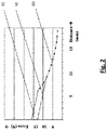
- The resulting opening characteristics of this two-stage fluid pressure controlled valve is shown in
Figure 2 , the opening characteristics for two different spring bias settings being indicated. - The invention is explained in more detail with the help of pictures but without limitation to them:
-
Figure 1 - Shows graphically the characteristics of a linear spring and a progressive spring while the non-linear characteristic of the progressive spring corresponds to the characteristic of a pair of permanent magnets facing each other with like poles -
Figure 2 - Shows graphically the opening characteristics of the bypass valve with the two-stage control according to the disclosed invention -
Figure 3 - Shows schematically a bypass valve structure model according to the presented invention -
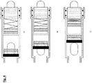
Figure 4 - Shows schematically a bypass valve model according to the presented invention in three working phases:- a) the bypass valve is closed
- b) the bypass valve opened partially on the basis of the setting mutual distance and force of the permanent magnets in the first working interval
- b) the bypass valve opened fully based on the setting of the mutual distance of the permanent magnets and force of the linear spring in the second working interval
- The
bypass valve 100 is composed of avalve housing 1 defining avalve chamber 2, an inlet opening 3 and an outlet opening 4 being arranged in the wall of thevalve housing 1, bothopenings valve chamber 2. Thevalve chamber 2 contains thepiston 7 that is movably arranged in it, the sealing surface of thepiston 7 is resting on thevalve housing 1 wall and on the inlet opening 3.
Thepiston 7 is provided with a firstpermanent magnet 5 on the side facing away from the inlet opening 3. The firstpermanent magnet 5 is made of a water-resistant material or has a water-resistant surface treatment. - A
waterproof cassette 9 is equipped with a secondpermanent magnet 6 and with alinear spring 8 and it is tightly inserted into thevalve chamber 2. Thewaterproof cassette 9 is closed with theplug 10 and thespring 8 is clamped between the secondpermanent magnet 6 and theplug 10.
Thewaterproof cassette 9 is placed in thebypass valve 100 so that it does not extend into any part of thevalve chamber 2 in which the inlet opening 3 and theoutlet opening 4 are arranged.
Advantageously, theplug 10 is provided with a thread for precise setting of thelinear spring 8 bias.
Thewaterproof cassette 9 is inserted into thevalve chamber 2 so that the firstpermanent magnet 5 and the secondpermanent magnet 6 are arranged at a distance allowing mutual force interaction, they face each other with like poles and their force interaction is repulsive. -
Figure 3 shows the water pressure acting on the inlet opening 3 in the direction indicated by an arrow. - As long as the water pressure acting on the
inlet opening 3 is lower than the system's differential pressure triggering the bypass function, thepiston 7 keeps theinlet opening 3 closed and the repulsive force of the magnets keeps thepiston 7 with its sealing surface inside thevalve chamber 2 in a position preventing mutual interconnection between theinlet opening 3 andoutlet opening 4. This working phase is shown schematically on theFigure 4 - a) . - When the pressure of the water acting on the
inlet opening 3 reaches the value triggering the bypass function, thepiston 7 and the firstpermanent magnet 5 move simultaneously in the water pressure direction and water flows from theinlet opening 3 to theoutlet opening 4 via thevalve chamber 2 into the bypass channel of the heating system. The minimum possible distance between thepermanent magnets non-linear characteristics Figure 4 - b) . - To completely open the flow of water through the
valve chamber 2, the differential water pressure acts against the resistance of thespring 8 so that the secondpermanent magnet 6 slides in thewaterproof cassette 9 and compresses thespring 8. In this working interval of thebypass valve 100, the linear characteristic 40 or 50 of thespring 8 is applied depending on its bias. This working phase is shown schematically on theFigure 4 - c) . - It is clear that the model does not include all possible alternative applications falling within the scope of protection, it is neither limited to a specific shape or design of permanent magnets and spring nor to the medium for which the valve is used. The bypass valve is also suitable for use with media other than hot water.
- The bypass valve controlled by the working medium pressure with the possibility to set its flow through the valve based on two working pressure levels is particularly suitable for hot water heating systems and also for other equipment requiring a bypass function. Due to its design, the disclosed bypass valve is more resistant to the influence of the medium than spring valves and therefore it can also be used for other equipment than hot water heating systems and media other than hot water. The design and surface treatment of permanent magnets are to meet the requirements of individual applications.
-
- 1 valve housing
- 2 valve chamber
- 3 inlet opening
- 4 outlet opening
- 5 first permanent magnet
- 6 second permanent magnet
- 7 piston
- 8 spring
- 9 waterproof casette
- 10 plug
- 20 characteristics of a pair of permanent magnets facing each other with like poles
- 30 linear coil spring characteristic
- 40 opening characteristics of the bypass valve with permanent magnets in the second working interval (the spring is set to a higher bias)
- 50 opening characteristics of the bypass valve with permanent magnets in the second working interval (the spring is set to a lower bias)
- 60 opening characteristics of the bypass valve with permanent magnets in the first working interval
- 100 bypass valve
Claims (3)
- A bypass valve (100), comprising- the valve housing (1) defining a valve chamber (2), wherein the valve housing (1) wall includes an inlet opening (3) and an outlet opening (4) and both openings (3, 4) are connected with the valve chamber (2),- the piston (7), which is is movably arranged in the valve chamber (2), comprising a sealing surface resting on the wall of the valve housing (1) and on the inlet opening (3),- the waterproof cassette (9) being closed by a plug (10),characterized in that
the piston (7) is provided with the first permanent magnet (5) being arranged on the side of the piston (7) facing away from the inlet opening (3), and
the waterproof casette (9) is tightly inserted into the valve chamber (2) not extend into any part of the valve chamber (2) in which the inlet opening (3) and the outlet opening (4) are arranged, and
the waterproof cassette (9) is provided with a second permanent magnet (6) and a linear spring (8), wherein the spring (8) is clamped between the second permanent valve (6) and the plug (10) and wherein the first permanent magnet (5) and the second permanent magnet (6) face each other with like poles. - The bypass valve (100) according the claim 1,
characterized in that the plug (10) is provided with a thread for setting the bias of the linear spring (8). - The bypass valve (100) according the claim 1,
characterized in that a pair of permanent magnets (5, 6) is used to adjust opening during the first working interval and the linear spring (8) is used to adjust opening during the second working interval.
Applications Claiming Priority (1)
| Application Number | Priority Date | Filing Date | Title |
|---|---|---|---|
| SK145-2019U SK8946Y1 (en) | 2019-10-01 | 2019-10-01 | Bypass valve |
Publications (2)
| Publication Number | Publication Date |
|---|---|
| EP3800387A1 true EP3800387A1 (en) | 2021-04-07 |
| EP3800387B1 EP3800387B1 (en) | 2022-09-07 |
Family
ID=71223014
Family Applications (1)
| Application Number | Title | Priority Date | Filing Date |
|---|---|---|---|
| EP20198030.7A Active EP3800387B1 (en) | 2019-10-01 | 2020-09-24 | By-pass valve |
Country Status (3)
| Country | Link |
|---|---|
| EP (1) | EP3800387B1 (en) |
| ES (1) | ES2928968T3 (en) |
| SK (1) | SK8946Y1 (en) |
Cited By (3)
| Publication number | Priority date | Publication date | Assignee | Title |
|---|---|---|---|---|
| CN115031044A (en) * | 2022-07-26 | 2022-09-09 | 山东科技大学 | An on-off pressure adjustable relief valve |
| US11603677B1 (en) * | 2022-04-06 | 2023-03-14 | Dongguan Hongyu Plastic Co., Ltd. | Spa bathtub and operating unit for the spa bathtub |
| US11612541B1 (en) | 2022-04-06 | 2023-03-28 | Dongguan Hongyu Plastics Co., Ltd | Spa bathtub and operating unit for the spa bathtub |
Citations (2)
| Publication number | Priority date | Publication date | Assignee | Title |
|---|---|---|---|---|
| US3877478A (en) * | 1972-09-11 | 1975-04-15 | Radiation Ltd | Fluid flow control valves |
| EP2835599A1 (en) | 2013-08-08 | 2015-02-11 | Vaillant GmbH | Primary heat exchanger of a condensing boiler |
-
2019
- 2019-10-01 SK SK145-2019U patent/SK8946Y1/en unknown
-
2020
- 2020-09-24 ES ES20198030T patent/ES2928968T3/en active Active
- 2020-09-24 EP EP20198030.7A patent/EP3800387B1/en active Active
Patent Citations (2)
| Publication number | Priority date | Publication date | Assignee | Title |
|---|---|---|---|---|
| US3877478A (en) * | 1972-09-11 | 1975-04-15 | Radiation Ltd | Fluid flow control valves |
| EP2835599A1 (en) | 2013-08-08 | 2015-02-11 | Vaillant GmbH | Primary heat exchanger of a condensing boiler |
Cited By (3)
| Publication number | Priority date | Publication date | Assignee | Title |
|---|---|---|---|---|
| US11603677B1 (en) * | 2022-04-06 | 2023-03-14 | Dongguan Hongyu Plastic Co., Ltd. | Spa bathtub and operating unit for the spa bathtub |
| US11612541B1 (en) | 2022-04-06 | 2023-03-28 | Dongguan Hongyu Plastics Co., Ltd | Spa bathtub and operating unit for the spa bathtub |
| CN115031044A (en) * | 2022-07-26 | 2022-09-09 | 山东科技大学 | An on-off pressure adjustable relief valve |
Also Published As
| Publication number | Publication date |
|---|---|
| SK8946Y1 (en) | 2020-12-02 |
| ES2928968T3 (en) | 2022-11-24 |
| EP3800387B1 (en) | 2022-09-07 |
| SK1452019U1 (en) | 2020-07-01 |
Similar Documents
| Publication | Publication Date | Title |
|---|---|---|
| EP3800387B1 (en) | By-pass valve | |
| US10851899B2 (en) | Reversing valve and household water purifier including same technical field | |
| ES2197288T3 (en) | MONOETAPA VARIABLE FORCE PRESSURE REGULATOR SOLENOID VALVE. | |
| EP3067772B1 (en) | Automatic balancing valve | |
| US4150788A (en) | Remote-controlled central air-conditioning system | |
| EP3428546A1 (en) | Electronically adjustable bypass valve integrated into the electronically controlled three-way valve | |
| US20110114204A1 (en) | Control valve | |
| MX2019010463A (en) | Pressure reducing valve with shut off. | |
| US8539978B2 (en) | Gas valve unit with bypass flow | |
| US4435127A (en) | Apparatus with latching effect for limiting pressure in liquid feeding systems | |
| EP1697669B1 (en) | Flow path control valve | |
| WO2016202635A1 (en) | Axial valve | |
| RU2658500C1 (en) | Valve device for a heat exchanger, heating system and method of heating system control | |
| EA201890116A2 (en) | DEVICE AND METHOD FOR REGULATING HEATING SYSTEMS | |
| CN214119038U (en) | Water return valve and water supply system | |
| KR100755392B1 (en) | A membrane valve with regulation means | |
| CN108730250B (en) | Mixing valve device of hydraulic system, oil cooling system and compressor system | |
| IES20150289A2 (en) | Satellite for central heating or for teleheating with multifunction presettings | |
| CN102003551B (en) | Diesel engine thermostat valve | |
| KR20120003789U (en) | A valve unit having a flow control valve | |
| CN218600017U (en) | Relief valve, heating system and water heater | |
| CN111594633A (en) | Three-way valve capable of being driven by pump | |
| EP1271026A1 (en) | Automatic valve with pressure dependent variable flow rate | |
| EP3693671B1 (en) | Filling system with thermal actuating device | |
| JPS5857573A (en) | Thermo sensitive valve |
Legal Events
| Date | Code | Title | Description |
|---|---|---|---|
| PUAI | Public reference made under article 153(3) epc to a published international application that has entered the european phase |
Free format text: ORIGINAL CODE: 0009012 |
|
| STAA | Information on the status of an ep patent application or granted ep patent |
Free format text: STATUS: THE APPLICATION HAS BEEN PUBLISHED |
|
| AK | Designated contracting states |
Kind code of ref document: A1 Designated state(s): AL AT BE BG CH CY CZ DE DK EE ES FI FR GB GR HR HU IE IS IT LI LT LU LV MC MK MT NL NO PL PT RO RS SE SI SK SM TR |
|
| AX | Request for extension of the european patent |
Extension state: BA ME |
|
| STAA | Information on the status of an ep patent application or granted ep patent |
Free format text: STATUS: REQUEST FOR EXAMINATION WAS MADE |
|
| 17P | Request for examination filed |
Effective date: 20210908 |
|
| RBV | Designated contracting states (corrected) |
Designated state(s): AL AT BE BG CH CY CZ DE DK EE ES FI FR GB GR HR HU IE IS IT LI LT LU LV MC MK MT NL NO PL PT RO RS SE SI SK SM TR |
|
| GRAP | Despatch of communication of intention to grant a patent |
Free format text: ORIGINAL CODE: EPIDOSNIGR1 |
|
| STAA | Information on the status of an ep patent application or granted ep patent |
Free format text: STATUS: GRANT OF PATENT IS INTENDED |
|
| INTG | Intention to grant announced |
Effective date: 20220318 |
|
| GRAS | Grant fee paid |
Free format text: ORIGINAL CODE: EPIDOSNIGR3 |
|
| GRAA | (expected) grant |
Free format text: ORIGINAL CODE: 0009210 |
|
| STAA | Information on the status of an ep patent application or granted ep patent |
Free format text: STATUS: THE PATENT HAS BEEN GRANTED |
|
| AK | Designated contracting states |
Kind code of ref document: B1 Designated state(s): AL AT BE BG CH CY CZ DE DK EE ES FI FR GB GR HR HU IE IS IT LI LT LU LV MC MK MT NL NO PL PT RO RS SE SI SK SM TR |
|
| REG | Reference to a national code |
Ref country code: GB Ref legal event code: FG4D |
|
| REG | Reference to a national code |
Ref country code: CH Ref legal event code: EP Ref country code: AT Ref legal event code: REF Ref document number: 1517307 Country of ref document: AT Kind code of ref document: T Effective date: 20220915 |
|
| REG | Reference to a national code |
Ref country code: IE Ref legal event code: FG4D |
|
| REG | Reference to a national code |
Ref country code: DE Ref legal event code: R096 Ref document number: 602020004952 Country of ref document: DE |
|
| REG | Reference to a national code |
Ref country code: ES Ref legal event code: FG2A Ref document number: 2928968 Country of ref document: ES Kind code of ref document: T3 Effective date: 20221124 |
|
| REG | Reference to a national code |
Ref country code: LT Ref legal event code: MG9D |
|
| REG | Reference to a national code |
Ref country code: NL Ref legal event code: MP Effective date: 20220907 |
|
| PG25 | Lapsed in a contracting state [announced via postgrant information from national office to epo] |
Ref country code: SE Free format text: LAPSE BECAUSE OF FAILURE TO SUBMIT A TRANSLATION OF THE DESCRIPTION OR TO PAY THE FEE WITHIN THE PRESCRIBED TIME-LIMIT Effective date: 20220907 Ref country code: RS Free format text: LAPSE BECAUSE OF FAILURE TO SUBMIT A TRANSLATION OF THE DESCRIPTION OR TO PAY THE FEE WITHIN THE PRESCRIBED TIME-LIMIT Effective date: 20220907 Ref country code: NO Free format text: LAPSE BECAUSE OF FAILURE TO SUBMIT A TRANSLATION OF THE DESCRIPTION OR TO PAY THE FEE WITHIN THE PRESCRIBED TIME-LIMIT Effective date: 20221207 Ref country code: LV Free format text: LAPSE BECAUSE OF FAILURE TO SUBMIT A TRANSLATION OF THE DESCRIPTION OR TO PAY THE FEE WITHIN THE PRESCRIBED TIME-LIMIT Effective date: 20220907 Ref country code: LT Free format text: LAPSE BECAUSE OF FAILURE TO SUBMIT A TRANSLATION OF THE DESCRIPTION OR TO PAY THE FEE WITHIN THE PRESCRIBED TIME-LIMIT Effective date: 20220907 Ref country code: FI Free format text: LAPSE BECAUSE OF FAILURE TO SUBMIT A TRANSLATION OF THE DESCRIPTION OR TO PAY THE FEE WITHIN THE PRESCRIBED TIME-LIMIT Effective date: 20220907 |
|
| REG | Reference to a national code |
Ref country code: AT Ref legal event code: MK05 Ref document number: 1517307 Country of ref document: AT Kind code of ref document: T Effective date: 20220907 |
|
| PG25 | Lapsed in a contracting state [announced via postgrant information from national office to epo] |
Ref country code: HR Free format text: LAPSE BECAUSE OF FAILURE TO SUBMIT A TRANSLATION OF THE DESCRIPTION OR TO PAY THE FEE WITHIN THE PRESCRIBED TIME-LIMIT Effective date: 20220907 Ref country code: GR Free format text: LAPSE BECAUSE OF FAILURE TO SUBMIT A TRANSLATION OF THE DESCRIPTION OR TO PAY THE FEE WITHIN THE PRESCRIBED TIME-LIMIT Effective date: 20221208 |
|
| PG25 | Lapsed in a contracting state [announced via postgrant information from national office to epo] |
Ref country code: SM Free format text: LAPSE BECAUSE OF FAILURE TO SUBMIT A TRANSLATION OF THE DESCRIPTION OR TO PAY THE FEE WITHIN THE PRESCRIBED TIME-LIMIT Effective date: 20220907 Ref country code: RO Free format text: LAPSE BECAUSE OF FAILURE TO SUBMIT A TRANSLATION OF THE DESCRIPTION OR TO PAY THE FEE WITHIN THE PRESCRIBED TIME-LIMIT Effective date: 20220907 Ref country code: PT Free format text: LAPSE BECAUSE OF FAILURE TO SUBMIT A TRANSLATION OF THE DESCRIPTION OR TO PAY THE FEE WITHIN THE PRESCRIBED TIME-LIMIT Effective date: 20230109 Ref country code: CZ Free format text: LAPSE BECAUSE OF FAILURE TO SUBMIT A TRANSLATION OF THE DESCRIPTION OR TO PAY THE FEE WITHIN THE PRESCRIBED TIME-LIMIT Effective date: 20220907 Ref country code: AT Free format text: LAPSE BECAUSE OF FAILURE TO SUBMIT A TRANSLATION OF THE DESCRIPTION OR TO PAY THE FEE WITHIN THE PRESCRIBED TIME-LIMIT Effective date: 20220907 |
|
| REG | Reference to a national code |
Ref country code: BE Ref legal event code: MM Effective date: 20220930 |
|
| PG25 | Lapsed in a contracting state [announced via postgrant information from national office to epo] |
Ref country code: SK Free format text: LAPSE BECAUSE OF FAILURE TO SUBMIT A TRANSLATION OF THE DESCRIPTION OR TO PAY THE FEE WITHIN THE PRESCRIBED TIME-LIMIT Effective date: 20220907 Ref country code: PL Free format text: LAPSE BECAUSE OF FAILURE TO SUBMIT A TRANSLATION OF THE DESCRIPTION OR TO PAY THE FEE WITHIN THE PRESCRIBED TIME-LIMIT Effective date: 20220907 Ref country code: IS Free format text: LAPSE BECAUSE OF FAILURE TO SUBMIT A TRANSLATION OF THE DESCRIPTION OR TO PAY THE FEE WITHIN THE PRESCRIBED TIME-LIMIT Effective date: 20230107 Ref country code: EE Free format text: LAPSE BECAUSE OF FAILURE TO SUBMIT A TRANSLATION OF THE DESCRIPTION OR TO PAY THE FEE WITHIN THE PRESCRIBED TIME-LIMIT Effective date: 20220907 |
|
| REG | Reference to a national code |
Ref country code: DE Ref legal event code: R097 Ref document number: 602020004952 Country of ref document: DE |
|
| PG25 | Lapsed in a contracting state [announced via postgrant information from national office to epo] |
Ref country code: NL Free format text: LAPSE BECAUSE OF FAILURE TO SUBMIT A TRANSLATION OF THE DESCRIPTION OR TO PAY THE FEE WITHIN THE PRESCRIBED TIME-LIMIT Effective date: 20220907 Ref country code: MC Free format text: LAPSE BECAUSE OF FAILURE TO SUBMIT A TRANSLATION OF THE DESCRIPTION OR TO PAY THE FEE WITHIN THE PRESCRIBED TIME-LIMIT Effective date: 20220907 Ref country code: LU Free format text: LAPSE BECAUSE OF NON-PAYMENT OF DUE FEES Effective date: 20220924 Ref country code: AL Free format text: LAPSE BECAUSE OF FAILURE TO SUBMIT A TRANSLATION OF THE DESCRIPTION OR TO PAY THE FEE WITHIN THE PRESCRIBED TIME-LIMIT Effective date: 20220907 |
|
| PLBE | No opposition filed within time limit |
Free format text: ORIGINAL CODE: 0009261 |
|
| STAA | Information on the status of an ep patent application or granted ep patent |
Free format text: STATUS: NO OPPOSITION FILED WITHIN TIME LIMIT |
|
| PG25 | Lapsed in a contracting state [announced via postgrant information from national office to epo] |
Ref country code: IE Free format text: LAPSE BECAUSE OF NON-PAYMENT OF DUE FEES Effective date: 20220924 Ref country code: DK Free format text: LAPSE BECAUSE OF FAILURE TO SUBMIT A TRANSLATION OF THE DESCRIPTION OR TO PAY THE FEE WITHIN THE PRESCRIBED TIME-LIMIT Effective date: 20220907 |
|
| 26N | No opposition filed |
Effective date: 20230608 |
|
| PG25 | Lapsed in a contracting state [announced via postgrant information from national office to epo] |
Ref country code: SI Free format text: LAPSE BECAUSE OF FAILURE TO SUBMIT A TRANSLATION OF THE DESCRIPTION OR TO PAY THE FEE WITHIN THE PRESCRIBED TIME-LIMIT Effective date: 20220907 |
|
| PG25 | Lapsed in a contracting state [announced via postgrant information from national office to epo] |
Ref country code: BE Free format text: LAPSE BECAUSE OF NON-PAYMENT OF DUE FEES Effective date: 20220930 |
|
| PGFP | Annual fee paid to national office [announced via postgrant information from national office to epo] |
Ref country code: FR Payment date: 20230922 Year of fee payment: 4 Ref country code: DE Payment date: 20230829 Year of fee payment: 4 |
|
| PGFP | Annual fee paid to national office [announced via postgrant information from national office to epo] |
Ref country code: ES Payment date: 20231002 Year of fee payment: 4 |
|
| PGFP | Annual fee paid to national office [announced via postgrant information from national office to epo] |
Ref country code: IT Payment date: 20230930 Year of fee payment: 4 |
|
| PG25 | Lapsed in a contracting state [announced via postgrant information from national office to epo] |
Ref country code: CY Free format text: LAPSE BECAUSE OF FAILURE TO SUBMIT A TRANSLATION OF THE DESCRIPTION OR TO PAY THE FEE WITHIN THE PRESCRIBED TIME-LIMIT Effective date: 20220907 |
|
| REG | Reference to a national code |
Ref country code: CH Ref legal event code: PL |
|
| PG25 | Lapsed in a contracting state [announced via postgrant information from national office to epo] |
Ref country code: MK Free format text: LAPSE BECAUSE OF FAILURE TO SUBMIT A TRANSLATION OF THE DESCRIPTION OR TO PAY THE FEE WITHIN THE PRESCRIBED TIME-LIMIT Effective date: 20220907 |
|
| PG25 | Lapsed in a contracting state [announced via postgrant information from national office to epo] |
Ref country code: CH Free format text: LAPSE BECAUSE OF NON-PAYMENT OF DUE FEES Effective date: 20230930 |
|
| PG25 | Lapsed in a contracting state [announced via postgrant information from national office to epo] |
Ref country code: HU Free format text: LAPSE BECAUSE OF FAILURE TO SUBMIT A TRANSLATION OF THE DESCRIPTION OR TO PAY THE FEE WITHIN THE PRESCRIBED TIME-LIMIT; INVALID AB INITIO Effective date: 20200924 Ref country code: CH Free format text: LAPSE BECAUSE OF NON-PAYMENT OF DUE FEES Effective date: 20230930 Ref country code: BG Free format text: LAPSE BECAUSE OF FAILURE TO SUBMIT A TRANSLATION OF THE DESCRIPTION OR TO PAY THE FEE WITHIN THE PRESCRIBED TIME-LIMIT Effective date: 20220907 |
|
| PG25 | Lapsed in a contracting state [announced via postgrant information from national office to epo] |
Ref country code: MT Free format text: LAPSE BECAUSE OF FAILURE TO SUBMIT A TRANSLATION OF THE DESCRIPTION OR TO PAY THE FEE WITHIN THE PRESCRIBED TIME-LIMIT Effective date: 20220907 |
|
| REG | Reference to a national code |
Ref country code: DE Ref legal event code: R119 Ref document number: 602020004952 Country of ref document: DE |
|
| GBPC | Gb: european patent ceased through non-payment of renewal fee |
Effective date: 20240924 |
|
| PG25 | Lapsed in a contracting state [announced via postgrant information from national office to epo] |
Ref country code: DE Free format text: LAPSE BECAUSE OF NON-PAYMENT OF DUE FEES Effective date: 20250401 |
|
| PG25 | Lapsed in a contracting state [announced via postgrant information from national office to epo] |
Ref country code: GB Free format text: LAPSE BECAUSE OF NON-PAYMENT OF DUE FEES Effective date: 20240924 |
|
| PG25 | Lapsed in a contracting state [announced via postgrant information from national office to epo] |
Ref country code: IT Free format text: LAPSE BECAUSE OF NON-PAYMENT OF DUE FEES Effective date: 20240924 |
|
| PG25 | Lapsed in a contracting state [announced via postgrant information from national office to epo] |
Ref country code: FR Free format text: LAPSE BECAUSE OF NON-PAYMENT OF DUE FEES Effective date: 20240930 |
|
| REG | Reference to a national code |
Ref country code: ES Ref legal event code: FD2A Effective date: 20251027 |
|
| PG25 | Lapsed in a contracting state [announced via postgrant information from national office to epo] |
Ref country code: TR Free format text: LAPSE BECAUSE OF FAILURE TO SUBMIT A TRANSLATION OF THE DESCRIPTION OR TO PAY THE FEE WITHIN THE PRESCRIBED TIME-LIMIT Effective date: 20220907 |
|
| PG25 | Lapsed in a contracting state [announced via postgrant information from national office to epo] |
Ref country code: ES Free format text: LAPSE BECAUSE OF NON-PAYMENT OF DUE FEES Effective date: 20240925 |
|
| PG25 | Lapsed in a contracting state [announced via postgrant information from national office to epo] |
Ref country code: CH Free format text: THE PATENT HAS BEEN ANNULLED BY A DECISION OF A NATIONAL AUTHORITY Effective date: 20230930 |