EP3800325A1 - Gas turbine engine with cooling passage circuit extending through blade, seal and ceramic vane - Google Patents
Gas turbine engine with cooling passage circuit extending through blade, seal and ceramic vane Download PDFInfo
- Publication number
- EP3800325A1 EP3800325A1 EP20199616.2A EP20199616A EP3800325A1 EP 3800325 A1 EP3800325 A1 EP 3800325A1 EP 20199616 A EP20199616 A EP 20199616A EP 3800325 A1 EP3800325 A1 EP 3800325A1
- Authority
- EP
- European Patent Office
- Prior art keywords
- seal
- blade
- passage
- ceramic
- gas turbine
- Prior art date
- Legal status (The legal status is an assumption and is not a legal conclusion. Google has not performed a legal analysis and makes no representation as to the accuracy of the status listed.)
- Granted
Links
Images


Classifications
-
- F—MECHANICAL ENGINEERING; LIGHTING; HEATING; WEAPONS; BLASTING
- F01—MACHINES OR ENGINES IN GENERAL; ENGINE PLANTS IN GENERAL; STEAM ENGINES
- F01D—NON-POSITIVE DISPLACEMENT MACHINES OR ENGINES, e.g. STEAM TURBINES
- F01D9/00—Stators
- F01D9/06—Fluid supply conduits to nozzles or the like
- F01D9/065—Fluid supply or removal conduits traversing the working fluid flow, e.g. for lubrication-, cooling-, or sealing fluids
-
- F—MECHANICAL ENGINEERING; LIGHTING; HEATING; WEAPONS; BLASTING
- F01—MACHINES OR ENGINES IN GENERAL; ENGINE PLANTS IN GENERAL; STEAM ENGINES
- F01D—NON-POSITIVE DISPLACEMENT MACHINES OR ENGINES, e.g. STEAM TURBINES
- F01D5/00—Blades; Blade-carrying members; Heating, heat-insulating, cooling or antivibration means on the blades or the members
- F01D5/02—Blade-carrying members, e.g. rotors
- F01D5/08—Heating, heat-insulating or cooling means
- F01D5/081—Cooling fluid being directed on the side of the rotor disc or at the roots of the blades
-
- F—MECHANICAL ENGINEERING; LIGHTING; HEATING; WEAPONS; BLASTING
- F01—MACHINES OR ENGINES IN GENERAL; ENGINE PLANTS IN GENERAL; STEAM ENGINES
- F01D—NON-POSITIVE DISPLACEMENT MACHINES OR ENGINES, e.g. STEAM TURBINES
- F01D5/00—Blades; Blade-carrying members; Heating, heat-insulating, cooling or antivibration means on the blades or the members
- F01D5/12—Blades
- F01D5/28—Selecting particular materials; Particular measures relating thereto; Measures against erosion or corrosion
- F01D5/282—Selecting composite materials, e.g. blades with reinforcing filaments
-
- F—MECHANICAL ENGINEERING; LIGHTING; HEATING; WEAPONS; BLASTING
- F01—MACHINES OR ENGINES IN GENERAL; ENGINE PLANTS IN GENERAL; STEAM ENGINES
- F01D—NON-POSITIVE DISPLACEMENT MACHINES OR ENGINES, e.g. STEAM TURBINES
- F01D5/00—Blades; Blade-carrying members; Heating, heat-insulating, cooling or antivibration means on the blades or the members
- F01D5/12—Blades
- F01D5/28—Selecting particular materials; Particular measures relating thereto; Measures against erosion or corrosion
- F01D5/284—Selection of ceramic materials
-
- F—MECHANICAL ENGINEERING; LIGHTING; HEATING; WEAPONS; BLASTING
- F01—MACHINES OR ENGINES IN GENERAL; ENGINE PLANTS IN GENERAL; STEAM ENGINES
- F01D—NON-POSITIVE DISPLACEMENT MACHINES OR ENGINES, e.g. STEAM TURBINES
- F01D5/00—Blades; Blade-carrying members; Heating, heat-insulating, cooling or antivibration means on the blades or the members
- F01D5/30—Fixing blades to rotors; Blade roots ; Blade spacers
- F01D5/3007—Fixing blades to rotors; Blade roots ; Blade spacers of axial insertion type
-
- F—MECHANICAL ENGINEERING; LIGHTING; HEATING; WEAPONS; BLASTING
- F01—MACHINES OR ENGINES IN GENERAL; ENGINE PLANTS IN GENERAL; STEAM ENGINES
- F01D—NON-POSITIVE DISPLACEMENT MACHINES OR ENGINES, e.g. STEAM TURBINES
- F01D11/00—Preventing or minimising internal leakage of working-fluid, e.g. between stages
- F01D11/001—Preventing or minimising internal leakage of working-fluid, e.g. between stages for sealing space between stator blade and rotor
-
- F—MECHANICAL ENGINEERING; LIGHTING; HEATING; WEAPONS; BLASTING
- F01—MACHINES OR ENGINES IN GENERAL; ENGINE PLANTS IN GENERAL; STEAM ENGINES
- F01D—NON-POSITIVE DISPLACEMENT MACHINES OR ENGINES, e.g. STEAM TURBINES
- F01D5/00—Blades; Blade-carrying members; Heating, heat-insulating, cooling or antivibration means on the blades or the members
- F01D5/12—Blades
- F01D5/14—Form or construction
- F01D5/18—Hollow blades, i.e. blades with cooling or heating channels or cavities; Heating, heat-insulating or cooling means on blades
- F01D5/187—Convection cooling
-
- F—MECHANICAL ENGINEERING; LIGHTING; HEATING; WEAPONS; BLASTING
- F05—INDEXING SCHEMES RELATING TO ENGINES OR PUMPS IN VARIOUS SUBCLASSES OF CLASSES F01-F04
- F05D—INDEXING SCHEME FOR ASPECTS RELATING TO NON-POSITIVE-DISPLACEMENT MACHINES OR ENGINES, GAS-TURBINES OR JET-PROPULSION PLANTS
- F05D2220/00—Application
- F05D2220/30—Application in turbines
- F05D2220/32—Application in turbines in gas turbines
-
- F—MECHANICAL ENGINEERING; LIGHTING; HEATING; WEAPONS; BLASTING
- F05—INDEXING SCHEMES RELATING TO ENGINES OR PUMPS IN VARIOUS SUBCLASSES OF CLASSES F01-F04
- F05D—INDEXING SCHEME FOR ASPECTS RELATING TO NON-POSITIVE-DISPLACEMENT MACHINES OR ENGINES, GAS-TURBINES OR JET-PROPULSION PLANTS
- F05D2240/00—Components
- F05D2240/10—Stators
- F05D2240/12—Fluid guiding means, e.g. vanes
-
- F—MECHANICAL ENGINEERING; LIGHTING; HEATING; WEAPONS; BLASTING
- F05—INDEXING SCHEMES RELATING TO ENGINES OR PUMPS IN VARIOUS SUBCLASSES OF CLASSES F01-F04
- F05D—INDEXING SCHEME FOR ASPECTS RELATING TO NON-POSITIVE-DISPLACEMENT MACHINES OR ENGINES, GAS-TURBINES OR JET-PROPULSION PLANTS
- F05D2240/00—Components
- F05D2240/20—Rotors
- F05D2240/24—Rotors for turbines
-
- F—MECHANICAL ENGINEERING; LIGHTING; HEATING; WEAPONS; BLASTING
- F05—INDEXING SCHEMES RELATING TO ENGINES OR PUMPS IN VARIOUS SUBCLASSES OF CLASSES F01-F04
- F05D—INDEXING SCHEME FOR ASPECTS RELATING TO NON-POSITIVE-DISPLACEMENT MACHINES OR ENGINES, GAS-TURBINES OR JET-PROPULSION PLANTS
- F05D2260/00—Function
- F05D2260/20—Heat transfer, e.g. cooling
- F05D2260/205—Cooling fluid recirculation, i.e. after cooling one or more components is the cooling fluid recovered and used elsewhere for other purposes
-
- F—MECHANICAL ENGINEERING; LIGHTING; HEATING; WEAPONS; BLASTING
- F05—INDEXING SCHEMES RELATING TO ENGINES OR PUMPS IN VARIOUS SUBCLASSES OF CLASSES F01-F04
- F05D—INDEXING SCHEME FOR ASPECTS RELATING TO NON-POSITIVE-DISPLACEMENT MACHINES OR ENGINES, GAS-TURBINES OR JET-PROPULSION PLANTS
- F05D2260/00—Function
- F05D2260/20—Heat transfer, e.g. cooling
- F05D2260/221—Improvement of heat transfer
-
- F—MECHANICAL ENGINEERING; LIGHTING; HEATING; WEAPONS; BLASTING
- F05—INDEXING SCHEMES RELATING TO ENGINES OR PUMPS IN VARIOUS SUBCLASSES OF CLASSES F01-F04
- F05D—INDEXING SCHEME FOR ASPECTS RELATING TO NON-POSITIVE-DISPLACEMENT MACHINES OR ENGINES, GAS-TURBINES OR JET-PROPULSION PLANTS
- F05D2260/00—Function
- F05D2260/94—Functionality given by mechanical stress related aspects such as low cycle fatigue [LCF] of high cycle fatigue [HCF]
- F05D2260/941—Functionality given by mechanical stress related aspects such as low cycle fatigue [LCF] of high cycle fatigue [HCF] particularly aimed at mechanical or thermal stress reduction
-
- F—MECHANICAL ENGINEERING; LIGHTING; HEATING; WEAPONS; BLASTING
- F05—INDEXING SCHEMES RELATING TO ENGINES OR PUMPS IN VARIOUS SUBCLASSES OF CLASSES F01-F04
- F05D—INDEXING SCHEME FOR ASPECTS RELATING TO NON-POSITIVE-DISPLACEMENT MACHINES OR ENGINES, GAS-TURBINES OR JET-PROPULSION PLANTS
- F05D2300/00—Materials; Properties thereof
- F05D2300/60—Properties or characteristics given to material by treatment or manufacturing
- F05D2300/603—Composites; e.g. fibre-reinforced
- F05D2300/6033—Ceramic matrix composites [CMC]
-
- Y—GENERAL TAGGING OF NEW TECHNOLOGICAL DEVELOPMENTS; GENERAL TAGGING OF CROSS-SECTIONAL TECHNOLOGIES SPANNING OVER SEVERAL SECTIONS OF THE IPC; TECHNICAL SUBJECTS COVERED BY FORMER USPC CROSS-REFERENCE ART COLLECTIONS [XRACs] AND DIGESTS
- Y02—TECHNOLOGIES OR APPLICATIONS FOR MITIGATION OR ADAPTATION AGAINST CLIMATE CHANGE
- Y02T—CLIMATE CHANGE MITIGATION TECHNOLOGIES RELATED TO TRANSPORTATION
- Y02T50/00—Aeronautics or air transport
- Y02T50/60—Efficient propulsion technologies, e.g. for aircraft
Definitions
- a gas turbine engine typically includes a fan section, a compressor section, a combustor section and a turbine section. Air entering the compressor section is compressed and delivered into the combustion section where it is mixed with fuel and ignited to generate a high-speed exhaust gas flow. The high-speed exhaust gas flow expands through the turbine section to drive the compressor and the fan section.
- the compressor section typically includes low and high pressure compressors, and the turbine section includes low and high pressure turbines.
- Airfoils in the turbine section are typically formed of a superalloy and may include thermal barrier coatings to extend temperature resistance. Ceramic matrix composite (“CMC”) materials are also being considered for airfoils. Among other attractive properties, CMCs have high temperature resistance and oxidation resistance. Despite these attributes, however, there are unique challenges to implementing CMCs in airfoils.
- CMC Ceramic matrix composite
- a gas turbine engine comprising a rotor carrying a blade, a ceramic vane adjacent the blade, and a seal carried on the rotor adjacent the tip of the ceramic vane.
- a cooling passage circuit extends through the blade, the seal, and the ceramic vane. The cooling passage circuit is configured to provide cooling air into the blade, then from the blade into the seal, and then from the seal into the ceramic vane.
- the cooling passage circuit includes a circuit leg in the blade.
- the circuit leg has a supply passage into the blade and a return passage connecting the supply passage with the seal.
- the cooling passage circuit includes a circuit leg in the seal.
- the circuit leg has an axial passage connected to receive cooling air from the blade, and a radial feed passage connecting the axial passage with the ceramic vane.
- the cooling passage circuit includes first and second circuit legs.
- the first circuit leg is in the blade and has a supply passage into the blade and a return passage connecting the supply passage with the seal
- the second circuit leg is in the seal and has an axial passage connected to receive cooling air from the return passage, and a radial feed passage connecting the axial passage with the ceramic vane.
- the seal is formed of ceramic.
- the rotor includes a disk and an axial support arm projecting from the disk and supporting the seal.
- the rotor includes a disk supporting the seal.
- the cooling passage circuit includes a radial inlet in the tip of the ceramic vane and a radial outlet in the seal which is in register with the radial inlet.
- the blade includes a compliant seal element sealing a supply passage into the blade from a return passage that connects the supply passage with the seal.
- a gas turbine engine comprising a forward stage that has a row of forward vanes followed by a row of forward blades.
- An aft stage has a row of aft ceramic vanes followed by a row of aft blades.
- a cooling passage circuit extends through the forward blades, the seals, and the aft ceramic vanes.
- the forward stage is a first turbine stage and the aft stage is a second turbine stage.
- the cooling passage circuit is configured to provide cooling air into the forward blades, then from the forward blades into the seals, and then from the seals into the aft ceramic vanes.
- the cooling passage circuit includes a circuit leg in the forward blades.
- the circuit leg has supply passages into the forward blades and return passages connecting the supply passages with the seals.
- the cooling passage circuit includes a circuit leg in the seals.
- the circuit leg has axial passages connected to receive cooling air from the forward blades, and radial feed passages connecting the axial passages with the aft ceramic vanes.
- the cooling passage circuit includes first and second circuit legs.
- the first circuit leg is in the forward blades and has supply passages into the forward blades and return passages connecting the supply passages with the seals
- the second circuit leg is in the seals and has axial passages connected to receive cooling air from the return passages, and radial feed passages connecting the axial passages with the aft ceramic vanes.
- the seals are formed of ceramic.
- the cooling passage circuit includes radial inlets in the tips of the aft ceramic vanes and radial outlets in the seals which are in register with the radial inlets.
- a method for cooling a ceramic vane comprising routing cooling air through a blade.
- the blade heats the cooling air to provide pre-heated cooling air.
- the pre-heated cooling air is then routed from the blade into a seal adjacent a tip of a ceramic vane, and then from the seal into the ceramic vane.
- the pre-heated cooling air maintains at least a portion of the ceramic vane at a thermal gradient of 150°C or less.
- FIG. 1 schematically illustrates a gas turbine engine 20.
- the gas turbine engine 20 is disclosed herein as a two-spool turbofan that generally incorporates a fan section 22, a compressor section 24, a combustor section 26 and a turbine section 28.
- the fan section 22 drives air along a bypass flow path B in a bypass duct defined within a nacelle 15, and also drives air along a core flow path C for compression and communication into the combustor section 26 then expansion through the turbine section 28.
- FIG. 1 schematically illustrates a gas turbine engine 20.
- the gas turbine engine 20 is disclosed herein as a two-spool turbofan that generally incorporates a fan section 22, a compressor section 24, a combustor section 26 and a turbine section 28.
- the fan section 22 drives air along a bypass flow path B in a bypass duct defined within a nacelle 15, and also drives air along a core flow path C for compression and communication into the combustor section 26 then expansion through the turbine section 28.
- FIG. 1 schematic
- the exemplary engine 20 generally includes a low speed spool 30 and a high speed spool 32 mounted for rotation about an engine central longitudinal axis A relative to an engine static structure 36 via several bearing systems 38. It should be understood that various bearing systems 38 at various locations may alternatively or additionally be provided, and the location of bearing systems 38 may be varied as appropriate to the application.
- the low speed spool 30 generally includes an inner shaft 40 that interconnects, a first (or low) pressure compressor 44 and a first (or low) pressure turbine 46.
- the inner shaft 40 is connected to the fan 42 through a speed change mechanism, which in exemplary gas turbine engine 20 is illustrated as a geared architecture 48 to drive a fan 42 at a lower speed than the low speed spool 30.
- the high speed spool 32 includes an outer shaft 50 that interconnects a second (or high) pressure compressor 52 and a second (or high) pressure turbine 54.
- a combustor 56 is arranged in exemplary gas turbine 20 between the high pressure compressor 52 and the high pressure turbine 54.
- a mid-turbine frame 57 of the engine static structure 36 may be arranged generally between the high pressure turbine 54 and the low pressure turbine 46.
- the mid-turbine frame 57 further supports bearing systems 38 in the turbine section 28.
- the inner shaft 40 and the outer shaft 50 are concentric and rotate via bearing systems 38 about the engine central longitudinal axis A which is colline
- the core airflow is compressed by the low pressure compressor 44 then the high pressure compressor 52, mixed and burned with fuel in the combustor 56, then expanded over the high pressure turbine 54 and low pressure turbine 46.
- the mid-turbine frame 57 includes airfoils 59 which are in the core airflow path C.
- the turbines 46, 54 rotationally drive the respective low speed spool 30 and high speed spool 32 in response to the expansion.
- gear system 48 may be located aft of the low pressure compressor, or aft of the combustor section 26 or even aft of turbine section 28, and fan 42 may be positioned forward or aft of the location of gear system 48.
- the engine 20 in one example is a high-bypass geared aircraft engine.
- the engine 20 bypass ratio is greater than about 6:1, with an example embodiment being greater than about 10:1
- the geared architecture 48 is an epicyclic gear train, such as a planetary gear system or other gear system, with a gear reduction ratio of greater than about 2.3:1 and the low pressure turbine 46 has a pressure ratio that is greater than about five.
- the engine 20 bypass ratio is greater than about 10:1
- the fan diameter is significantly larger than that of the low pressure compressor 44
- the low pressure turbine 46 has a pressure ratio that is greater than about 5:1.
- the low pressure turbine 46 pressure ratio is pressure measured prior to the inlet of low pressure turbine 46 as related to the pressure at the outlet of the low pressure turbine 46 prior to an exhaust nozzle.
- the geared architecture 48 may be an epicycle gear train, such as a planetary gear system or other gear system, with a gear reduction ratio of greater than about 2.3:1 and less than about 5:1. It should be understood, however, that the above parameters are only exemplary of one embodiment of a geared architecture engine and that the present invention is applicable to other gas turbine engines including but not limited to direct drive turbofans.
- the fan section 22 of the engine 20 is designed for a particular flight condition -- typically cruise at about 0.8 Mach and about 35,000 feet (10,668 meters).
- the flight condition of 0.8 Mach and 35,000 ft (10,668 meters), with the engine at its best fuel consumption - also known as "bucket cruise Thrust Specific Fuel Consumption ('TSFC')" - is the industry standard parameter of lbm of fuel being burned divided by lbf of thrust the engine produces at that minimum point.
- "Low fan pressure ratio” is the pressure ratio across the fan blade alone, without a Fan Exit Guide Vane (“FEGV”) system.
- the low fan pressure ratio as disclosed herein according to one non-limiting embodiment is less than about 1.45:1.
- the "Low corrected fan tip speed” as disclosed herein according to one non-limiting embodiment is less than about 1150 ft / second (350.5 meters/second).
- Figure 2 illustrates a portion of the high pressure turbine 54.
- the turbine 54 includes a first or forward stage 62 and a second or aft stage 64.
- a "stage” is comprised of one row of static vanes followed by one row of rotatable blades.
- the forward stage 62 includes a row of forward vanes 66 followed by a row of forward blades 68
- the aft stage 64 includes a row of aft vanes 70 followed by a row of aft blades 72.
- first or “forward” indicates that the stage 62 is upstream of the stage 64 with regard to the flow of gases through the core gas path C.
- the first stage 62 may also be the initial stage of the high pressure turbine 54, immediately after the combustor 56. It is to be understood, however, that although the stages 62/64 may be shown or described herein with reference to the high pressure turbine 54, the examples herein are applicable to other, downstream stages as well as stages in the low pressure turbine 46.
- the blades 68/72 are carried on a rotor 74, which may include rotor disks 76.
- the rotor disks 76 include axial slots 78 in which roots of the respective blades 68/72 fit to secure the blades 68/72.
- the rotor 74 additionally carries seals 80 axially between the rotor disks 76.
- the seals 80 are located adjacent tips 70a of the vanes 70.
- the seals 80 serve as a gas seal around the vane inner diameter below platform region 70a of the vanes 70.
- the seals 80 may include one or more seal elements 80a that cooperate with associated seal elements 80b on the vanes 70 to provide sealing.
- the seal elements 80a are knife edges and the seal elements 80b are abradable elements, such as honeycomb elements.
- the seals 80 are not particularly limited to knife edge seals and may instead employ other types of seals, such as but not limited to, noncontacting hydrodynamic seals.
- At least the vanes 70 of the second stage 64 are formed of ceramic.
- the seals 80 may also be formed of ceramic, for weight savings.
- the ceramic may be a monolithic ceramic or a ceramic matrix composite ("CMC").
- Example ceramic material may include, but is not limited to, silicon-containing ceramics.
- the silicon-containing ceramic may be, but is not limited to, silicon carbide (SiC) or silicon nitride (Si 3 N 4 ).
- An example CMC may be a SiC/SiC CMC in which SiC fibers are disposed within a SiC matrix.
- formed of' refers to the structural self-supporting body of the component, rather than a conformal body such as a coating.
- vanes that are formed of ceramic present thermal management challenges that are unlike metallic vanes.
- Metallic alloys used for vanes have relatively high strength and ductility.
- the ductility enables the metallic vanes to withstand high thermal gradients between exterior surfaces in the core gas path and interior surfaces that are cooled.
- Ceramic materials have relatively higher thermal resistance, but lower thermal conductivity and lower ductility in comparison to metallic materials.
- cooling a ceramic vane may actually be detrimental to durability because high thermal gradients may cause thermal stresses that exceed the limits of the ceramic.
- the engine 20 includes a cooling passage circuit, represented at 82, that serves to pre-heat cooling air before the cooling air is provided into the vanes 70.
- the pre-heated cooling air provides a cooling effect in the vanes 70 but, due to the pre-heating, enables the vane 70 to maintain lower thermal gradients in comparison to non-pre-heated cooling.
- the cooling passage circuit 82 is connected to receive cooling air from a cooling air source 84.
- the cooling air source 84 is generally radially inwards of the blades 68 and may be, but is not limited to, a tangential onboard injector.
- the cooling passage circuit 82 is comprised of a network of interconnected passages among the blades 68, seals 80, and vanes 70.
- the cooling passage circuit 82 includes several circuit legs, or sections.
- a first, or initial, circuit leg 86 of the cooling passage circuit 82 is in the blades 68 and includes an inlet 86a, a manifold passage 86b, one or more supply passages 86c, and one or more return passages 86d.
- the inlet 86a is an entrance to the manifold passage 86.
- the inlet 86a may be in the root section of the blade 68.
- the manifold passage 86b is a generally axially-oriented passage in the root.
- the supply passage or passages 86c extend off of the manifold passage 86b into the airfoil section of the blade 68. As shown in the sectioned view of the blade 68 in Figure 3 , the blade 68 may have multiple supply passages 86c, which may include but are not limited to one or more of a central cavity, leading end cavity, or skincore passages within walls of the blade 68.
- the supply passage or passages 86c connect to the return passage or passages 86d.
- the blade 68 may include one or more turn sections 68a that serve to turn the flow of cooling air from one or more supply passages 86c into one or more return passages 86d.
- the turn section 68a may be part of a serpentine configuration of the supply passages 86c, for example.
- the return passage or passages 86d connect the supply passage or passages 86c to the seal 80.
- the return passage or passages 76d extend radially from the airfoil section of the blade 68 into the root of the blade 68 and then extend axially in the root to an outlet 86e at the aft side of the blade 68 near the seal 80.
- the axial extent of the return passage 86d leading to the outlet 86e may be an extension of the manifold passage 86b that is sealed off from the remaining portion of the manifold passage 86b that connects to the supply passages 86c.
- a passage seal 87 may be disposed in the manifold passage 86b to isolate the supply side from the return side.
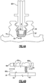
- Figure 4A illustrates an axial view of one example of the passage seal 87 disposed in the slot 78
- Figure 4B illustrates a sectioned view according to the section line shown in Figure 4A
- the seal 87 is compressible and is disposed in a post or rib 89 that projects from the root of the blade 68. The seal abuts the floor and sides of the slot 78 to thereby divide the manifold passage 86b so that incoming and exiting cooling air in the manifold passage 86b do not readily mix.
- the seals 80 are mounted immediately adjacent the blades 68.
- the seals 80 are supported on an axial supports 76a.
- Edge seals 77 may be provided at the fore and aft locations of the seal 80, to facilitate limiting of cooling air between the seal 80 and the blade 68.
- the edge seals 77 may be, but are not limited to, wire seals.
- a second circuit leg or section 88 of the cooling passage circuit 82 is in the seals 80.
- the second circuit section 88 includes an inlet 88a, an axial passage 88b, and a radial feed passage 88c.
- the inlet 88a is an entrance to the axial passage 88b.
- the inlet 88a is in register with the outlet 86e of the return passage or passages 86d, to receive cooling air therefrom.
- the axial passage 88b extends axially through the seal 80 and connects the inlet 88a with the radial feed passage 88c.
- the radial feed passage 88c extends radially to a radial outlet 88d adjacent the vane inner diameter below platform region 70a of the vane 70.
- the radial outlet 88d is axially between knife edges 80a.
- a third circuit leg or section 90 of the cooling passage circuit 82 is in the vanes 70.
- the third circuit section 90 includes a radial inlet 90a and one or more cooling passages 90b.
- the radial inlet 90a is an entrance to the cooling passage or passages 90b.
- the radial inlet 90a is in register with the radial outlet 88d of the seal 80.
- the cooling air source 84 provides cooling air to the cooling passage circuit 82.
- the cooling air is initially provided through the inlet 76a and into the manifold passage 86b.
- the cooling air then flows from the manifold passage 86b into the one or more supply passages 86c.
- the cooling air in the supply passages 86c picks up heat from the walls of the blade 68, thereby substantially increasing in temperature.
- the cooling air then flows into the return passage or passages 76d, picking up additional heat, before being discharged from the outlet 86e to the inlet 88a of the seal 80.
- the temperature increase of the cooling air from the inlet 86a to the outlet 86e may vary depending on the stage location and starting temperature of the cooling air.
- the cooling air starting temperature is TOBI exit temperature 84
- this is a function of compressor exit temperature and any cooling or heating in the air delivery circuit prior to 86a.
- the cooling air picks up heat from the inner walls of the turbine blade and thus may be pre-heated to increase in temperature by an amount of 50°C to 400°C.
- the pre-heated cooling air is then received through the inlet 88a of the seal 80 into the axial passage 88b.
- the pre-heated cooling air then flows axially along the axial passage 88b to the radial feed passage 88c.
- the pre-heated cooling air may pick up additional heat from windage in the seal 80 as the seal 80 rotates with the rotor 74.
- the radial feed passage 88c discharges the pre-heated cooling air radially through the radial outlet 88d. As the radial outlet 88d is in register with the radial inlet 90a of the vanes 70, the pre-heated cooling air is received into the vanes 70, where it then flows through the cooling passage or passages 90b to cool the vane 70.
- outlet 88d and inlet 90a at the seal elements 80a/80b may also facilitate cooling air flow between the rotating seal 80 and the stationary vane 70, as this region is sealed from the gas flow in the core gas path C and thus shields the cooling air from being stripped away.
- the cooling air received into the vane 70 is warmer than it otherwise would have been if received directly from the cooling air source 84.
- the pre-heated cooling air is warmer by 50°C to 400°C.
- the relatively warmer pre-heated cooling air maintains at least a portion of the vane 70 at a desired thermal gradient. For instance, if cooling air were used directly from the cooling air source 84, the internal surfaces of the vane 70 would be cooled to a greater degree, thereby creating relatively large thermal gradient with exterior surfaces of the vane 70. Wall or rib through-thickness thermal gradients can thus exceed temperature differentials of 400°C or more.
- the pre-heated cooling air cools the internal surfaces of the vane 70 to a lesser degree, thereby enabling lower thermal gradients.
- wall or rib through-thickness thermal gradients may be maintained at a temperature differential of 150°C or less.
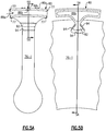
- the seals 80 are supported on an additional disk 76-1, e.g., a "minidisk,” located would be between the rotor disks 76 in Figure 2 .
- the disk 76-1 may be referred to as a "minidisk.”
- the seal 80 has a root 92 that interlocks with a slot 94 in the disk 76-1.
- a pad or pads 94 may be provided between the sides of the root 92 and the sides of the slot 94, to facilitate a reduction in wear and limit direct contact between the ceramic of the seal 80 and the superalloy, such as a nickel-based alloy, that the disk 76-1 is formed of.
Landscapes
- Engineering & Computer Science (AREA)
- Mechanical Engineering (AREA)
- General Engineering & Computer Science (AREA)
- Chemical & Material Sciences (AREA)
- Materials Engineering (AREA)
- Physics & Mathematics (AREA)
- Fluid Mechanics (AREA)
- Composite Materials (AREA)
- Ceramic Engineering (AREA)
- Combustion & Propulsion (AREA)
- Turbine Rotor Nozzle Sealing (AREA)
Abstract
Description
- A gas turbine engine typically includes a fan section, a compressor section, a combustor section and a turbine section. Air entering the compressor section is compressed and delivered into the combustion section where it is mixed with fuel and ignited to generate a high-speed exhaust gas flow. The high-speed exhaust gas flow expands through the turbine section to drive the compressor and the fan section. The compressor section typically includes low and high pressure compressors, and the turbine section includes low and high pressure turbines.
- Airfoils in the turbine section are typically formed of a superalloy and may include thermal barrier coatings to extend temperature resistance. Ceramic matrix composite ("CMC") materials are also being considered for airfoils. Among other attractive properties, CMCs have high temperature resistance and oxidation resistance. Despite these attributes, however, there are unique challenges to implementing CMCs in airfoils.
- According to a first aspect of the present invention there is provided a gas turbine engine comprising a rotor carrying a blade, a ceramic vane adjacent the blade, and a seal carried on the rotor adjacent the tip of the ceramic vane. A cooling passage circuit extends through the blade, the seal, and the ceramic vane. The cooling passage circuit is configured to provide cooling air into the blade, then from the blade into the seal, and then from the seal into the ceramic vane.
- In an embodiment of any of the above embodiments, the cooling passage circuit includes a circuit leg in the blade. The circuit leg has a supply passage into the blade and a return passage connecting the supply passage with the seal.
- In an embodiment of any of the above embodiments, the cooling passage circuit includes a circuit leg in the seal. The circuit leg has an axial passage connected to receive cooling air from the blade, and a radial feed passage connecting the axial passage with the ceramic vane.
- In an embodiment of any of the above embodiments, the cooling passage circuit includes first and second circuit legs. The first circuit leg is in the blade and has a supply passage into the blade and a return passage connecting the supply passage with the seal, and the second circuit leg is in the seal and has an axial passage connected to receive cooling air from the return passage, and a radial feed passage connecting the axial passage with the ceramic vane.
- In an embodiment of any of the above embodiments, the seal is formed of ceramic.
- In an embodiment of any of the above embodiments, the rotor includes a disk and an axial support arm projecting from the disk and supporting the seal.
- In an embodiment of any of the above embodiments, the rotor includes a disk supporting the seal.
- In an embodiment of any of the above embodiments, the cooling passage circuit includes a radial inlet in the tip of the ceramic vane and a radial outlet in the seal which is in register with the radial inlet.
- In an embodiment of any of the above embodiments, the blade includes a compliant seal element sealing a supply passage into the blade from a return passage that connects the supply passage with the seal.
- According to a second aspect of the present invention there is provided a gas turbine engine comprising a forward stage that has a row of forward vanes followed by a row of forward blades. An aft stage has a row of aft ceramic vanes followed by a row of aft blades. There are seals adjacent the tips of the aft ceramic vanes. A cooling passage circuit extends through the forward blades, the seals, and the aft ceramic vanes.
- In an embodiment of any of the above embodiments, the forward stage is a first turbine stage and the aft stage is a second turbine stage.
- The gas turbine engine as recited in claim 10, further comprising a cooling air source radially inwards of the forward blades.
- In an embodiment of any of the above embodiments, the cooling passage circuit is configured to provide cooling air into the forward blades, then from the forward blades into the seals, and then from the seals into the aft ceramic vanes.
- In an embodiment of any of the above embodiments, the cooling passage circuit includes a circuit leg in the forward blades. The circuit leg has supply passages into the forward blades and return passages connecting the supply passages with the seals.
- In an embodiment of any of the above embodiments, the cooling passage circuit includes a circuit leg in the seals. The circuit leg has axial passages connected to receive cooling air from the forward blades, and radial feed passages connecting the axial passages with the aft ceramic vanes.
- In an embodiment of any of the above embodiments, the cooling passage circuit includes first and second circuit legs. The first circuit leg is in the forward blades and has supply passages into the forward blades and return passages connecting the supply passages with the seals, and the second circuit leg is in the seals and has axial passages connected to receive cooling air from the return passages, and radial feed passages connecting the axial passages with the aft ceramic vanes.
- In an embodiment of any of the above embodiments, the seals are formed of ceramic.
- In an embodiment of any of the above embodiments, the cooling passage circuit includes radial inlets in the tips of the aft ceramic vanes and radial outlets in the seals which are in register with the radial inlets.
- According to a third aspect of the present invention there is provided a method for cooling a ceramic vane comprising routing cooling air through a blade. The blade heats the cooling air to provide pre-heated cooling air. The pre-heated cooling air is then routed from the blade into a seal adjacent a tip of a ceramic vane, and then from the seal into the ceramic vane.
- In an embodiment of any of the above embodiments, the pre-heated cooling air maintains at least a portion of the ceramic vane at a thermal gradient of 150°C or less.
- The various features and advantages of the present disclosure will become apparent to those skilled in the art from the following detailed description. The drawings that accompany the detailed description can be briefly described as follows.
-
Figure 1 illustrates an embodiment of a gas turbine engine according to the present invention. -
Figure 2 illustrates an embodiment of a portion of a turbine section of the engine according to the present invention. -
Figure 3 illustrates a sectioned view of an embodiment of a blade according to the present invention. -
Figure 4A illustrates an axial view of an embodiment of a seal in the blade according to the present invention. -
Figure 4B illustrates a sectioned view of the blade ofFigure 4A . -
Figure 5A illustrates a view of an embodiment of a seal supported on a minidisk according to the present invention. -
Figure 5B illustrates a sectioned view of the seal and minidisk ofFigure 5A . -
Figure 1 schematically illustrates agas turbine engine 20. Thegas turbine engine 20 is disclosed herein as a two-spool turbofan that generally incorporates afan section 22, acompressor section 24, a combustor section 26 and aturbine section 28. Thefan section 22 drives air along a bypass flow path B in a bypass duct defined within anacelle 15, and also drives air along a core flow path C for compression and communication into the combustor section 26 then expansion through theturbine section 28. Although depicted as a two-spool turbofan gas turbine engine in the disclosed non-limiting embodiment, it should be understood that the concepts described herein are not limited to use with two-spool turbofans as the teachings may be applied to other types of turbine engines including but not limited to three-spool architectures. - The
exemplary engine 20 generally includes alow speed spool 30 and ahigh speed spool 32 mounted for rotation about an engine central longitudinal axis A relative to an enginestatic structure 36 viaseveral bearing systems 38. It should be understood thatvarious bearing systems 38 at various locations may alternatively or additionally be provided, and the location ofbearing systems 38 may be varied as appropriate to the application. - The
low speed spool 30 generally includes aninner shaft 40 that interconnects, a first (or low) pressure compressor 44 and a first (or low)pressure turbine 46. Theinner shaft 40 is connected to thefan 42 through a speed change mechanism, which in exemplarygas turbine engine 20 is illustrated as a gearedarchitecture 48 to drive afan 42 at a lower speed than thelow speed spool 30. Thehigh speed spool 32 includes anouter shaft 50 that interconnects a second (or high)pressure compressor 52 and a second (or high)pressure turbine 54. Acombustor 56 is arranged inexemplary gas turbine 20 between thehigh pressure compressor 52 and thehigh pressure turbine 54. Amid-turbine frame 57 of the enginestatic structure 36 may be arranged generally between thehigh pressure turbine 54 and thelow pressure turbine 46. Themid-turbine frame 57 furthersupports bearing systems 38 in theturbine section 28. Theinner shaft 40 and theouter shaft 50 are concentric and rotate via bearingsystems 38 about the engine central longitudinal axis A which is collinear with their longitudinal axes. - The core airflow is compressed by the low pressure compressor 44 then the
high pressure compressor 52, mixed and burned with fuel in thecombustor 56, then expanded over thehigh pressure turbine 54 andlow pressure turbine 46. Themid-turbine frame 57 includesairfoils 59 which are in the core airflow path C. Theturbines low speed spool 30 andhigh speed spool 32 in response to the expansion. It will be appreciated that each of the positions of thefan section 22,compressor section 24, combustor section 26,turbine section 28, and fandrive gear system 48 may be varied. For example,gear system 48 may be located aft of the low pressure compressor, or aft of the combustor section 26 or even aft ofturbine section 28, andfan 42 may be positioned forward or aft of the location ofgear system 48. - The
engine 20 in one example is a high-bypass geared aircraft engine. In a further example, theengine 20 bypass ratio is greater than about 6:1, with an example embodiment being greater than about 10:1, the gearedarchitecture 48 is an epicyclic gear train, such as a planetary gear system or other gear system, with a gear reduction ratio of greater than about 2.3:1 and thelow pressure turbine 46 has a pressure ratio that is greater than about five. In one disclosed embodiment, theengine 20 bypass ratio is greater than about 10:1, the fan diameter is significantly larger than that of the low pressure compressor 44, and thelow pressure turbine 46 has a pressure ratio that is greater than about 5:1. Thelow pressure turbine 46 pressure ratio is pressure measured prior to the inlet oflow pressure turbine 46 as related to the pressure at the outlet of thelow pressure turbine 46 prior to an exhaust nozzle. The gearedarchitecture 48 may be an epicycle gear train, such as a planetary gear system or other gear system, with a gear reduction ratio of greater than about 2.3:1 and less than about 5:1. It should be understood, however, that the above parameters are only exemplary of one embodiment of a geared architecture engine and that the present invention is applicable to other gas turbine engines including but not limited to direct drive turbofans. - A significant amount of thrust is provided by the bypass flow B due to the high bypass ratio. The
fan section 22 of theengine 20 is designed for a particular flight condition -- typically cruise at about 0.8 Mach and about 35,000 feet (10,668 meters). The flight condition of 0.8 Mach and 35,000 ft (10,668 meters), with the engine at its best fuel consumption - also known as "bucket cruise Thrust Specific Fuel Consumption ('TSFC')" - is the industry standard parameter of lbm of fuel being burned divided by lbf of thrust the engine produces at that minimum point. "Low fan pressure ratio" is the pressure ratio across the fan blade alone, without a Fan Exit Guide Vane ("FEGV") system. The low fan pressure ratio as disclosed herein according to one non-limiting embodiment is less than about 1.45:1. "Low corrected fan tip speed" is the actual fan tip speed in ft/sec divided by an industry standard temperature correction of [(Tram °R) / (518.7 °R)]0.5 (where °R = K x 9/5). The "Low corrected fan tip speed" as disclosed herein according to one non-limiting embodiment is less than about 1150 ft / second (350.5 meters/second). -
Figure 2 illustrates a portion of thehigh pressure turbine 54. Theturbine 54 includes a first orforward stage 62 and a second oraft stage 64. A "stage" is comprised of one row of static vanes followed by one row of rotatable blades. Here, theforward stage 62 includes a row offorward vanes 66 followed by a row offorward blades 68, and theaft stage 64 includes a row ofaft vanes 70 followed by a row ofaft blades 72. In this example, "first" or "forward" indicates that thestage 62 is upstream of thestage 64 with regard to the flow of gases through the core gas path C. Thefirst stage 62 may also be the initial stage of thehigh pressure turbine 54, immediately after thecombustor 56. It is to be understood, however, that although thestages 62/64 may be shown or described herein with reference to thehigh pressure turbine 54, the examples herein are applicable to other, downstream stages as well as stages in thelow pressure turbine 46. - The
blades 68/72 are carried on arotor 74, which may includerotor disks 76. For example, therotor disks 76 includeaxial slots 78 in which roots of therespective blades 68/72 fit to secure theblades 68/72. Therotor 74 additionally carriesseals 80 axially between therotor disks 76. Theseals 80 are locatedadjacent tips 70a of thevanes 70. Theseals 80 serve as a gas seal around the vane inner diameter belowplatform region 70a of thevanes 70. Theseals 80 may include one ormore seal elements 80a that cooperate with associatedseal elements 80b on thevanes 70 to provide sealing. As shown, theseal elements 80a are knife edges and theseal elements 80b are abradable elements, such as honeycomb elements. Theseals 80, however, are not particularly limited to knife edge seals and may instead employ other types of seals, such as but not limited to, noncontacting hydrodynamic seals. - At least the
vanes 70 of thesecond stage 64 are formed of ceramic. Theseals 80 may also be formed of ceramic, for weight savings. The ceramic may be a monolithic ceramic or a ceramic matrix composite ("CMC"). Example ceramic material may include, but is not limited to, silicon-containing ceramics. The silicon-containing ceramic may be, but is not limited to, silicon carbide (SiC) or silicon nitride (Si3N4). An example CMC may be a SiC/SiC CMC in which SiC fibers are disposed within a SiC matrix. As used herein, "formed of' refers to the structural self-supporting body of the component, rather than a conformal body such as a coating. - In general, vanes that are formed of ceramic present thermal management challenges that are unlike metallic vanes. Metallic alloys used for vanes have relatively high strength and ductility. Thus, although metallic vanes are often cooled, the ductility enables the metallic vanes to withstand high thermal gradients between exterior surfaces in the core gas path and interior surfaces that are cooled. Ceramic materials have relatively higher thermal resistance, but lower thermal conductivity and lower ductility in comparison to metallic materials. As a result, cooling a ceramic vane may actually be detrimental to durability because high thermal gradients may cause thermal stresses that exceed the limits of the ceramic. In this regard, the
engine 20 includes a cooling passage circuit, represented at 82, that serves to pre-heat cooling air before the cooling air is provided into thevanes 70. The pre-heated cooling air provides a cooling effect in thevanes 70 but, due to the pre-heating, enables thevane 70 to maintain lower thermal gradients in comparison to non-pre-heated cooling. - The
cooling passage circuit 82 is connected to receive cooling air from a coolingair source 84. The coolingair source 84 is generally radially inwards of theblades 68 and may be, but is not limited to, a tangential onboard injector. - The
cooling passage circuit 82 is comprised of a network of interconnected passages among theblades 68, seals 80, andvanes 70. Thecooling passage circuit 82 includes several circuit legs, or sections. A first, or initial,circuit leg 86 of thecooling passage circuit 82 is in theblades 68 and includes aninlet 86a, amanifold passage 86b, one ormore supply passages 86c, and one ormore return passages 86d. Theinlet 86a is an entrance to themanifold passage 86. For example, theinlet 86a may be in the root section of theblade 68. Themanifold passage 86b is a generally axially-oriented passage in the root. The supply passage orpassages 86c extend off of themanifold passage 86b into the airfoil section of theblade 68. As shown in the sectioned view of theblade 68 inFigure 3 , theblade 68 may havemultiple supply passages 86c, which may include but are not limited to one or more of a central cavity, leading end cavity, or skincore passages within walls of theblade 68. - The supply passage or
passages 86c connect to the return passage orpassages 86d. For example, as shown inFigure 2 , theblade 68 may include one ormore turn sections 68a that serve to turn the flow of cooling air from one ormore supply passages 86c into one ormore return passages 86d. Theturn section 68a may be part of a serpentine configuration of thesupply passages 86c, for example. - The return passage or
passages 86d connect the supply passage orpassages 86c to theseal 80. For example, the return passage or passages 76d extend radially from the airfoil section of theblade 68 into the root of theblade 68 and then extend axially in the root to anoutlet 86e at the aft side of theblade 68 near theseal 80. The axial extent of thereturn passage 86d leading to theoutlet 86e may be an extension of themanifold passage 86b that is sealed off from the remaining portion of themanifold passage 86b that connects to thesupply passages 86c. For instance, apassage seal 87 may be disposed in themanifold passage 86b to isolate the supply side from the return side.Figure 4A illustrates an axial view of one example of thepassage seal 87 disposed in theslot 78, andFigure 4B illustrates a sectioned view according to the section line shown inFigure 4A . As an example theseal 87 is compressible and is disposed in a post orrib 89 that projects from the root of theblade 68. The seal abuts the floor and sides of theslot 78 to thereby divide themanifold passage 86b so that incoming and exiting cooling air in themanifold passage 86b do not readily mix. - The
seals 80 are mounted immediately adjacent theblades 68. In the illustrated example, theseals 80 are supported on anaxial supports 76a. Edge seals 77 may be provided at the fore and aft locations of theseal 80, to facilitate limiting of cooling air between theseal 80 and theblade 68. The edge seals 77 may be, but are not limited to, wire seals. - A second circuit leg or section 88 of the
cooling passage circuit 82 is in theseals 80. The second circuit section 88 includes aninlet 88a, anaxial passage 88b, and aradial feed passage 88c. Theinlet 88a is an entrance to theaxial passage 88b. Theinlet 88a is in register with theoutlet 86e of the return passage orpassages 86d, to receive cooling air therefrom. Theaxial passage 88b extends axially through theseal 80 and connects theinlet 88a with theradial feed passage 88c. Theradial feed passage 88c extends radially to a radial outlet 88d adjacent the vane inner diameter belowplatform region 70a of thevane 70. In this example, the radial outlet 88d is axially betweenknife edges 80a. - Referring to
Figure 2 , a third circuit leg orsection 90 of thecooling passage circuit 82 is in thevanes 70. Thethird circuit section 90 includes aradial inlet 90a and one ormore cooling passages 90b. Theradial inlet 90a is an entrance to the cooling passage orpassages 90b. Theradial inlet 90a is in register with the radial outlet 88d of theseal 80. - When the
engine 20 is in operation, the coolingair source 84 provides cooling air to thecooling passage circuit 82. The cooling air is initially provided through theinlet 76a and into themanifold passage 86b. The cooling air then flows from themanifold passage 86b into the one ormore supply passages 86c. The cooling air in thesupply passages 86c picks up heat from the walls of theblade 68, thereby substantially increasing in temperature. The cooling air then flows into the return passage or passages 76d, picking up additional heat, before being discharged from theoutlet 86e to theinlet 88a of theseal 80. - The temperature increase of the cooling air from the
inlet 86a to theoutlet 86e may vary depending on the stage location and starting temperature of the cooling air. However, in one example in which thestage 62 is the initial stage of thehigh pressure turbine 54, the cooling air starting temperature isTOBI exit temperature 84, this is a function of compressor exit temperature and any cooling or heating in the air delivery circuit prior to 86a.. The cooling air picks up heat from the inner walls of the turbine blade and thus may be pre-heated to increase in temperature by an amount of 50°C to 400°C. - The pre-heated cooling air is then received through the
inlet 88a of theseal 80 into theaxial passage 88b. The pre-heated cooling air then flows axially along theaxial passage 88b to theradial feed passage 88c. The pre-heated cooling air may pick up additional heat from windage in theseal 80 as theseal 80 rotates with therotor 74. Theradial feed passage 88c discharges the pre-heated cooling air radially through the radial outlet 88d. As the radial outlet 88d is in register with theradial inlet 90a of thevanes 70, the pre-heated cooling air is received into thevanes 70, where it then flows through the cooling passage orpassages 90b to cool thevane 70. The location of the outlet 88d andinlet 90a at theseal elements 80a/80b may also facilitate cooling air flow between therotating seal 80 and thestationary vane 70, as this region is sealed from the gas flow in the core gas path C and thus shields the cooling air from being stripped away. - By first flowing through the
blade 68 to be pre-heated, the cooling air received into thevane 70 is warmer than it otherwise would have been if received directly from the coolingair source 84. For instance, based on the example above, the pre-heated cooling air is warmer by 50°C to 400°C. The relatively warmer pre-heated cooling air maintains at least a portion of thevane 70 at a desired thermal gradient. For instance, if cooling air were used directly from the coolingair source 84, the internal surfaces of thevane 70 would be cooled to a greater degree, thereby creating relatively large thermal gradient with exterior surfaces of thevane 70. Wall or rib through-thickness thermal gradients can thus exceed temperature differentials of 400°C or more. However, the pre-heated cooling air cools the internal surfaces of thevane 70 to a lesser degree, thereby enabling lower thermal gradients. As an example, wall or rib through-thickness thermal gradients may be maintained at a temperature differential of 150°C or less. - The approach of using cooling air in a ceramic vane that is pre-heated in a blade is contrary to paradigms used in metallic vanes, where maximized cooling is typically desired. For the ceramic vanes as disclosed herein, maximized cooling would be likely to debit durability. Instead, the
vanes 70 are cooled to a lesser degree than is possible. This enables reductions in thermal gradient temperature differentials between exterior and interior surfaces, which in turn facilitates reductions in thermal stresses to increase durability. Moreover, the use of the same cooling air in theblades 68 andvanes 70 may facilitate reductions in the amount of air used in comparison to using separate dedicated cooling streams to the blades and to the vanes. - In one alternate example shown in
Figures 5A and 5B , rather than thesupports 76a, theseals 80 are supported on an additional disk 76-1, e.g., a "minidisk," located would be between therotor disks 76 inFigure 2 . For instance, the disk 76-1 may be referred to as a "minidisk." In this example, theseal 80 has aroot 92 that interlocks with aslot 94 in the disk 76-1. A pad orpads 94 may be provided between the sides of theroot 92 and the sides of theslot 94, to facilitate a reduction in wear and limit direct contact between the ceramic of theseal 80 and the superalloy, such as a nickel-based alloy, that the disk 76-1 is formed of. Additionally, in any of the examples herein, there may be oneseal 80 perblade 68, or two ormore seals 80 perblade 68. - Although a combination of features is shown in the illustrated examples, not all of them need to be combined to realize the benefits of various embodiments of this disclosure. In other words, a system designed according to an embodiment of this disclosure will not necessarily include all of the features shown in any one of the Figures or all of the portions schematically shown in the Figures. Moreover, selected features of one example embodiment may be combined with selected features of other example embodiments.
- The preceding description is exemplary rather than limiting in nature. Variations and modifications to the disclosed examples may become apparent to those skilled in the art that do not necessarily depart from this disclosure. The scope of legal protection given to this disclosure can only be determined by studying the following claims.
Claims (14)
- A gas turbine engine (20) comprising:a rotor (74) carrying a blade (68, 72);a ceramic vane (66, 70) adjacent the blade (68, 72);a seal (80) carried on the rotor (74) adjacent the tip of the ceramic vane (70); anda cooling passage circuit (82) extending through the blade (68), the seal (80), and the ceramic vane (70), the cooling passage circuit (82) configured to provide cooling air into the blade (68), then from the blade (68) into the seal (80), and then from the seal (80) into the ceramic vane (70).
- The gas turbine engine (20) as recited in claim 1, wherein the rotor (74) includes a disk (76-1) and an axial support arm projecting from the disk (76-1) and supporting the seal (80).
- The gas turbine engine (20) as recited in claim 1, wherein the rotor (74) includes a disk (76-1) supporting the seal (80).
- The gas turbine engine (20) as recited in claim 1, wherein the blade (68) includes a compliant seal element (87) sealing a supply passage (86c) into the blade (68) from a return passage (86d) that connects the supply passage (86c) with the seal (80).
- A gas turbine engine (20) comprising:a forward stage (62) including a row of forward vanes (66) followed by a row of forward blades (66);an aft stage (64) including a row of aft ceramic vanes (70) followed by a row of aft blades (68, 72);seals (80) adjacent the tips of the aft ceramic vanes (70); anda cooling passage circuit (82) extending through the forward blades (68), the seals (80), and the aft ceramic vanes (70).
- The gas turbine engine (20) as recited in claim 5, wherein the forward stage (62) is a first turbine stage and the aft stage (64) is a second turbine stage.
- The gas turbine engine (20) as recited in claim 5 or 6, further comprising a cooling air source (84) radially inwards of the forward blades (68).
- The gas turbine engine (20) as recited in any of claims 5 to 7, wherein the cooling passage circuit (82) is configured to provide cooling air into the forward blades (68), then from the forward blades (68) into the seals (80), and then from the seals into the aft ceramic vanes (70).
- The gas turbine engine (20) as recited in any of claims 1 to 8, wherein the cooling passage circuit (82) includes a circuit leg (86) in the blade (68), the circuit leg (86) including a supply passage (86c) into the blade (68) and a return passage (86d) connecting the supply passage (86c) with the seal (80).
- The gas turbine engine (20) as recited in any of claims 1 to 9, wherein the cooling passage circuit (82) includes a circuit leg (88) in the seal (80), the circuit leg (88) including an axial passage (88b) connected to receive cooling air from the blade (68), and a radial feed passage (88c) connecting the axial passage (88b) with the ceramic vane (70).
- The gas turbine engine (20) as recited in any of claims 1 to 10, wherein the seal (80) is formed of ceramic.
- The gas turbine engine (20) as recited in any of claims 1 to 11, wherein the cooling passage circuit (82) includes a radial inlet (90a) in the tip of the ceramic vane (70) and a radial outlet (88d) in the seal (80) which is in register with the radial inlet (90a).
- A method for cooling a ceramic vane, the method comprising:routing cooling air (84) through a blade (68), the blade (68) heating the cooling air (84) to provide pre-heated cooling air;routing the pre-heated cooling air from the blade (68) into a seal adjacent a tip of a ceramic vane (70); androuting the pre-heated cooling air from the seal (80) into the ceramic vane (70).
- The method as recited in claim 13, wherein the pre-heated cooling air maintains at least a portion of the ceramic vane (70) at a thermal gradient of 150°C or less.
Applications Claiming Priority (1)
| Application Number | Priority Date | Filing Date | Title |
|---|---|---|---|
| US16/592,916 US11359503B2 (en) | 2019-10-04 | 2019-10-04 | Engine with cooling passage circuit extending through blade, seal, and ceramic vane |
Publications (2)
| Publication Number | Publication Date |
|---|---|
| EP3800325A1 true EP3800325A1 (en) | 2021-04-07 |
| EP3800325B1 EP3800325B1 (en) | 2023-06-28 |
Family
ID=72717765
Family Applications (1)
| Application Number | Title | Priority Date | Filing Date |
|---|---|---|---|
| EP20199616.2A Active EP3800325B1 (en) | 2019-10-04 | 2020-10-01 | Gas turbine engine with cooling passage circuit extending through blade, seal and ceramic vane |
Country Status (2)
| Country | Link |
|---|---|
| US (1) | US11359503B2 (en) |
| EP (1) | EP3800325B1 (en) |
Citations (5)
| Publication number | Priority date | Publication date | Assignee | Title |
|---|---|---|---|---|
| JPH07317562A (en) * | 1994-05-25 | 1995-12-05 | Mitsubishi Heavy Ind Ltd | Gas turbine |
| EP1033484A2 (en) * | 1999-03-02 | 2000-09-06 | General Electric Company | Gas turbine cooling system |
| US20070295011A1 (en) * | 2004-12-01 | 2007-12-27 | United Technologies Corporation | Regenerative Turbine Blade and Vane Cooling for a Tip Turbine Engine |
| EP2820278A1 (en) * | 2012-02-27 | 2015-01-07 | United Technologies Corporation | Hybrid turbofan engine |
| US20160290157A1 (en) * | 2015-03-31 | 2016-10-06 | General Electric Company | System for cooling a turbine engine |
Family Cites Families (6)
| Publication number | Priority date | Publication date | Assignee | Title |
|---|---|---|---|---|
| US3291447A (en) | 1965-02-15 | 1966-12-13 | Gen Electric | Steam turbine rotor cooling |
| US5706647A (en) * | 1994-11-15 | 1998-01-13 | Solar Turbines Incorporated | Airfoil structure |
| GB2307279B (en) | 1995-11-14 | 1999-11-17 | Rolls Royce Plc | A gas turbine engine |
| CA2633319C (en) * | 2005-12-29 | 2013-02-19 | Rolls-Royce Power Engineering Plc | First stage turbine airfoil |
| US10590786B2 (en) * | 2016-05-03 | 2020-03-17 | General Electric Company | System and method for cooling components of a gas turbine engine |
| US10633996B2 (en) | 2016-11-17 | 2020-04-28 | Rolls-Royce Corporation | Turbine cooling system |
-
2019
- 2019-10-04 US US16/592,916 patent/US11359503B2/en active Active
-
2020
- 2020-10-01 EP EP20199616.2A patent/EP3800325B1/en active Active
Patent Citations (5)
| Publication number | Priority date | Publication date | Assignee | Title |
|---|---|---|---|---|
| JPH07317562A (en) * | 1994-05-25 | 1995-12-05 | Mitsubishi Heavy Ind Ltd | Gas turbine |
| EP1033484A2 (en) * | 1999-03-02 | 2000-09-06 | General Electric Company | Gas turbine cooling system |
| US20070295011A1 (en) * | 2004-12-01 | 2007-12-27 | United Technologies Corporation | Regenerative Turbine Blade and Vane Cooling for a Tip Turbine Engine |
| EP2820278A1 (en) * | 2012-02-27 | 2015-01-07 | United Technologies Corporation | Hybrid turbofan engine |
| US20160290157A1 (en) * | 2015-03-31 | 2016-10-06 | General Electric Company | System for cooling a turbine engine |
Also Published As
| Publication number | Publication date |
|---|---|
| EP3800325B1 (en) | 2023-06-28 |
| US20210102494A1 (en) | 2021-04-08 |
| US11359503B2 (en) | 2022-06-14 |
Similar Documents
| Publication | Publication Date | Title |
|---|---|---|
| US11326463B2 (en) | BOAS thermal baffle | |
| US11021986B2 (en) | Seal assembly for gas turbine engine | |
| US11781486B2 (en) | Ceramic component having silicon layer and barrier layer | |
| US12123307B2 (en) | Air seal system with backside abradable layer | |
| EP4317648A1 (en) | Vane multiplet with conjoined singlet vanes | |
| US11242762B2 (en) | Vane with collar | |
| EP3767075A1 (en) | Assembly with blade outer air seal formed of ceramic matrix composite | |
| EP3767076A1 (en) | Assembly with blade outer air seal formed of ceramic matrix composite | |
| US11187096B2 (en) | Platform seal | |
| US11248482B2 (en) | CMC BOAS arrangement | |
| US11105214B2 (en) | CMC BOAS arrangement | |
| EP3800325B1 (en) | Gas turbine engine with cooling passage circuit extending through blade, seal and ceramic vane | |
| US12215606B2 (en) | Turbine engine with TOBI supporting vanes | |
| EP4086433B1 (en) | Seal assembly with seal arc segment | |
| US11492914B1 (en) | Engine with cooling passage circuit for air prior to ceramic component | |
| US10968772B2 (en) | Attachment block for blade outer air seal providing convection cooling | |
| EP4071337B1 (en) | Ceramic component with support structure |
Legal Events
| Date | Code | Title | Description |
|---|---|---|---|
| PUAI | Public reference made under article 153(3) epc to a published international application that has entered the european phase |
Free format text: ORIGINAL CODE: 0009012 |
|
| STAA | Information on the status of an ep patent application or granted ep patent |
Free format text: STATUS: THE APPLICATION HAS BEEN PUBLISHED |
|
| AK | Designated contracting states |
Kind code of ref document: A1 Designated state(s): AL AT BE BG CH CY CZ DE DK EE ES FI FR GB GR HR HU IE IS IT LI LT LU LV MC MK MT NL NO PL PT RO RS SE SI SK SM TR |
|
| AX | Request for extension of the european patent |
Extension state: BA ME |
|
| STAA | Information on the status of an ep patent application or granted ep patent |
Free format text: STATUS: REQUEST FOR EXAMINATION WAS MADE |
|
| 17P | Request for examination filed |
Effective date: 20211005 |
|
| RBV | Designated contracting states (corrected) |
Designated state(s): AL AT BE BG CH CY CZ DE DK EE ES FI FR GB GR HR HU IE IS IT LI LT LU LV MC MK MT NL NO PL PT RO RS SE SI SK SM TR |
|
| GRAP | Despatch of communication of intention to grant a patent |
Free format text: ORIGINAL CODE: EPIDOSNIGR1 |
|
| STAA | Information on the status of an ep patent application or granted ep patent |
Free format text: STATUS: GRANT OF PATENT IS INTENDED |
|
| INTG | Intention to grant announced |
Effective date: 20230110 |
|
| RIN1 | Information on inventor provided before grant (corrected) |
Inventor name: ZELESKY, MARK F. |
|
| GRAS | Grant fee paid |
Free format text: ORIGINAL CODE: EPIDOSNIGR3 |
|
| GRAA | (expected) grant |
Free format text: ORIGINAL CODE: 0009210 |
|
| STAA | Information on the status of an ep patent application or granted ep patent |
Free format text: STATUS: THE PATENT HAS BEEN GRANTED |
|
| AK | Designated contracting states |
Kind code of ref document: B1 Designated state(s): AL AT BE BG CH CY CZ DE DK EE ES FI FR GB GR HR HU IE IS IT LI LT LU LV MC MK MT NL NO PL PT RO RS SE SI SK SM TR |
|
| REG | Reference to a national code |
Ref country code: CH Ref legal event code: EP |
|
| REG | Reference to a national code |
Ref country code: AT Ref legal event code: REF Ref document number: 1582841 Country of ref document: AT Kind code of ref document: T Effective date: 20230715 |
|
| REG | Reference to a national code |
Ref country code: IE Ref legal event code: FG4D |
|
| REG | Reference to a national code |
Ref country code: DE Ref legal event code: R096 Ref document number: 602020012955 Country of ref document: DE |
|
| REG | Reference to a national code |
Ref country code: LT Ref legal event code: MG9D |
|
| PG25 | Lapsed in a contracting state [announced via postgrant information from national office to epo] |
Ref country code: SE Free format text: LAPSE BECAUSE OF FAILURE TO SUBMIT A TRANSLATION OF THE DESCRIPTION OR TO PAY THE FEE WITHIN THE PRESCRIBED TIME-LIMIT Effective date: 20230628 Ref country code: NO Free format text: LAPSE BECAUSE OF FAILURE TO SUBMIT A TRANSLATION OF THE DESCRIPTION OR TO PAY THE FEE WITHIN THE PRESCRIBED TIME-LIMIT Effective date: 20230928 |
|
| RAP4 | Party data changed (patent owner data changed or rights of a patent transferred) |
Owner name: RTX CORPORATION |
|
| REG | Reference to a national code |
Ref country code: NL Ref legal event code: MP Effective date: 20230628 |
|
| REG | Reference to a national code |
Ref country code: AT Ref legal event code: MK05 Ref document number: 1582841 Country of ref document: AT Kind code of ref document: T Effective date: 20230628 |
|
| PG25 | Lapsed in a contracting state [announced via postgrant information from national office to epo] |
Ref country code: RS Free format text: LAPSE BECAUSE OF FAILURE TO SUBMIT A TRANSLATION OF THE DESCRIPTION OR TO PAY THE FEE WITHIN THE PRESCRIBED TIME-LIMIT Effective date: 20230628 Ref country code: NL Free format text: LAPSE BECAUSE OF FAILURE TO SUBMIT A TRANSLATION OF THE DESCRIPTION OR TO PAY THE FEE WITHIN THE PRESCRIBED TIME-LIMIT Effective date: 20230628 Ref country code: LV Free format text: LAPSE BECAUSE OF FAILURE TO SUBMIT A TRANSLATION OF THE DESCRIPTION OR TO PAY THE FEE WITHIN THE PRESCRIBED TIME-LIMIT Effective date: 20230628 Ref country code: LT Free format text: LAPSE BECAUSE OF FAILURE TO SUBMIT A TRANSLATION OF THE DESCRIPTION OR TO PAY THE FEE WITHIN THE PRESCRIBED TIME-LIMIT Effective date: 20230628 Ref country code: HR Free format text: LAPSE BECAUSE OF FAILURE TO SUBMIT A TRANSLATION OF THE DESCRIPTION OR TO PAY THE FEE WITHIN THE PRESCRIBED TIME-LIMIT Effective date: 20230628 Ref country code: GR Free format text: LAPSE BECAUSE OF FAILURE TO SUBMIT A TRANSLATION OF THE DESCRIPTION OR TO PAY THE FEE WITHIN THE PRESCRIBED TIME-LIMIT Effective date: 20230929 |
|
| PG25 | Lapsed in a contracting state [announced via postgrant information from national office to epo] |
Ref country code: FI Free format text: LAPSE BECAUSE OF FAILURE TO SUBMIT A TRANSLATION OF THE DESCRIPTION OR TO PAY THE FEE WITHIN THE PRESCRIBED TIME-LIMIT Effective date: 20230628 |
|
| PG25 | Lapsed in a contracting state [announced via postgrant information from national office to epo] |
Ref country code: SK Free format text: LAPSE BECAUSE OF FAILURE TO SUBMIT A TRANSLATION OF THE DESCRIPTION OR TO PAY THE FEE WITHIN THE PRESCRIBED TIME-LIMIT Effective date: 20230628 |
|
| PG25 | Lapsed in a contracting state [announced via postgrant information from national office to epo] |
Ref country code: ES Free format text: LAPSE BECAUSE OF FAILURE TO SUBMIT A TRANSLATION OF THE DESCRIPTION OR TO PAY THE FEE WITHIN THE PRESCRIBED TIME-LIMIT Effective date: 20230628 |
|
| PG25 | Lapsed in a contracting state [announced via postgrant information from national office to epo] |
Ref country code: IS Free format text: LAPSE BECAUSE OF FAILURE TO SUBMIT A TRANSLATION OF THE DESCRIPTION OR TO PAY THE FEE WITHIN THE PRESCRIBED TIME-LIMIT Effective date: 20231028 |
|
| PG25 | Lapsed in a contracting state [announced via postgrant information from national office to epo] |
Ref country code: SM Free format text: LAPSE BECAUSE OF FAILURE TO SUBMIT A TRANSLATION OF THE DESCRIPTION OR TO PAY THE FEE WITHIN THE PRESCRIBED TIME-LIMIT Effective date: 20230628 Ref country code: SK Free format text: LAPSE BECAUSE OF FAILURE TO SUBMIT A TRANSLATION OF THE DESCRIPTION OR TO PAY THE FEE WITHIN THE PRESCRIBED TIME-LIMIT Effective date: 20230628 Ref country code: RO Free format text: LAPSE BECAUSE OF FAILURE TO SUBMIT A TRANSLATION OF THE DESCRIPTION OR TO PAY THE FEE WITHIN THE PRESCRIBED TIME-LIMIT Effective date: 20230628 Ref country code: PT Free format text: LAPSE BECAUSE OF FAILURE TO SUBMIT A TRANSLATION OF THE DESCRIPTION OR TO PAY THE FEE WITHIN THE PRESCRIBED TIME-LIMIT Effective date: 20231030 Ref country code: IS Free format text: LAPSE BECAUSE OF FAILURE TO SUBMIT A TRANSLATION OF THE DESCRIPTION OR TO PAY THE FEE WITHIN THE PRESCRIBED TIME-LIMIT Effective date: 20231028 Ref country code: ES Free format text: LAPSE BECAUSE OF FAILURE TO SUBMIT A TRANSLATION OF THE DESCRIPTION OR TO PAY THE FEE WITHIN THE PRESCRIBED TIME-LIMIT Effective date: 20230628 Ref country code: EE Free format text: LAPSE BECAUSE OF FAILURE TO SUBMIT A TRANSLATION OF THE DESCRIPTION OR TO PAY THE FEE WITHIN THE PRESCRIBED TIME-LIMIT Effective date: 20230628 Ref country code: CZ Free format text: LAPSE BECAUSE OF FAILURE TO SUBMIT A TRANSLATION OF THE DESCRIPTION OR TO PAY THE FEE WITHIN THE PRESCRIBED TIME-LIMIT Effective date: 20230628 Ref country code: AT Free format text: LAPSE BECAUSE OF FAILURE TO SUBMIT A TRANSLATION OF THE DESCRIPTION OR TO PAY THE FEE WITHIN THE PRESCRIBED TIME-LIMIT Effective date: 20230628 |
|
| PG25 | Lapsed in a contracting state [announced via postgrant information from national office to epo] |
Ref country code: PL Free format text: LAPSE BECAUSE OF FAILURE TO SUBMIT A TRANSLATION OF THE DESCRIPTION OR TO PAY THE FEE WITHIN THE PRESCRIBED TIME-LIMIT Effective date: 20230628 |
|
| REG | Reference to a national code |
Ref country code: DE Ref legal event code: R097 Ref document number: 602020012955 Country of ref document: DE |
|
| PG25 | Lapsed in a contracting state [announced via postgrant information from national office to epo] |
Ref country code: DK Free format text: LAPSE BECAUSE OF FAILURE TO SUBMIT A TRANSLATION OF THE DESCRIPTION OR TO PAY THE FEE WITHIN THE PRESCRIBED TIME-LIMIT Effective date: 20230628 |
|
| PLBE | No opposition filed within time limit |
Free format text: ORIGINAL CODE: 0009261 |
|
| STAA | Information on the status of an ep patent application or granted ep patent |
Free format text: STATUS: NO OPPOSITION FILED WITHIN TIME LIMIT |
|
| PG25 | Lapsed in a contracting state [announced via postgrant information from national office to epo] |
Ref country code: IT Free format text: LAPSE BECAUSE OF FAILURE TO SUBMIT A TRANSLATION OF THE DESCRIPTION OR TO PAY THE FEE WITHIN THE PRESCRIBED TIME-LIMIT Effective date: 20230628 Ref country code: MC Free format text: LAPSE BECAUSE OF FAILURE TO SUBMIT A TRANSLATION OF THE DESCRIPTION OR TO PAY THE FEE WITHIN THE PRESCRIBED TIME-LIMIT Effective date: 20230628 |
|
| REG | Reference to a national code |
Ref country code: CH Ref legal event code: PL |
|
| 26N | No opposition filed |
Effective date: 20240402 |
|
| REG | Reference to a national code |
Ref country code: BE Ref legal event code: MM Effective date: 20231031 |
|
| PG25 | Lapsed in a contracting state [announced via postgrant information from national office to epo] |
Ref country code: LU Free format text: LAPSE BECAUSE OF NON-PAYMENT OF DUE FEES Effective date: 20231001 |
|
| PG25 | Lapsed in a contracting state [announced via postgrant information from national office to epo] |
Ref country code: LU Free format text: LAPSE BECAUSE OF NON-PAYMENT OF DUE FEES Effective date: 20231001 |
|
| PG25 | Lapsed in a contracting state [announced via postgrant information from national office to epo] |
Ref country code: CH Free format text: LAPSE BECAUSE OF NON-PAYMENT OF DUE FEES Effective date: 20231031 |
|
| PG25 | Lapsed in a contracting state [announced via postgrant information from national office to epo] |
Ref country code: CH Free format text: LAPSE BECAUSE OF NON-PAYMENT OF DUE FEES Effective date: 20231031 Ref country code: SI Free format text: LAPSE BECAUSE OF FAILURE TO SUBMIT A TRANSLATION OF THE DESCRIPTION OR TO PAY THE FEE WITHIN THE PRESCRIBED TIME-LIMIT Effective date: 20230628 |
|
| PG25 | Lapsed in a contracting state [announced via postgrant information from national office to epo] |
Ref country code: BE Free format text: LAPSE BECAUSE OF NON-PAYMENT OF DUE FEES Effective date: 20231031 |
|
| PG25 | Lapsed in a contracting state [announced via postgrant information from national office to epo] |
Ref country code: IE Free format text: LAPSE BECAUSE OF NON-PAYMENT OF DUE FEES Effective date: 20231001 |
|
| PG25 | Lapsed in a contracting state [announced via postgrant information from national office to epo] |
Ref country code: IE Free format text: LAPSE BECAUSE OF NON-PAYMENT OF DUE FEES Effective date: 20231001 |
|
| PG25 | Lapsed in a contracting state [announced via postgrant information from national office to epo] |
Ref country code: BG Free format text: LAPSE BECAUSE OF FAILURE TO SUBMIT A TRANSLATION OF THE DESCRIPTION OR TO PAY THE FEE WITHIN THE PRESCRIBED TIME-LIMIT Effective date: 20230628 |
|
| PG25 | Lapsed in a contracting state [announced via postgrant information from national office to epo] |
Ref country code: BG Free format text: LAPSE BECAUSE OF FAILURE TO SUBMIT A TRANSLATION OF THE DESCRIPTION OR TO PAY THE FEE WITHIN THE PRESCRIBED TIME-LIMIT Effective date: 20230628 |
|
| PG25 | Lapsed in a contracting state [announced via postgrant information from national office to epo] |
Ref country code: CY Free format text: LAPSE BECAUSE OF FAILURE TO SUBMIT A TRANSLATION OF THE DESCRIPTION OR TO PAY THE FEE WITHIN THE PRESCRIBED TIME-LIMIT; INVALID AB INITIO Effective date: 20201001 |
|
| PG25 | Lapsed in a contracting state [announced via postgrant information from national office to epo] |
Ref country code: HU Free format text: LAPSE BECAUSE OF FAILURE TO SUBMIT A TRANSLATION OF THE DESCRIPTION OR TO PAY THE FEE WITHIN THE PRESCRIBED TIME-LIMIT; INVALID AB INITIO Effective date: 20201001 |
|
| REG | Reference to a national code |
Ref country code: DE Ref legal event code: R081 Ref document number: 602020012955 Country of ref document: DE Owner name: RTX CORPORATION (N.D.GES.D. STAATES DELAWARE),, US Free format text: FORMER OWNER: RAYTHEON TECHNOLOGIES CORPORATION, FARMINGTON, CT, US |
|
| PGFP | Annual fee paid to national office [announced via postgrant information from national office to epo] |
Ref country code: GB Payment date: 20250923 Year of fee payment: 6 |
|
| PGFP | Annual fee paid to national office [announced via postgrant information from national office to epo] |
Ref country code: FR Payment date: 20250924 Year of fee payment: 6 |
|
| PG25 | Lapsed in a contracting state [announced via postgrant information from national office to epo] |
Ref country code: TR Free format text: LAPSE BECAUSE OF FAILURE TO SUBMIT A TRANSLATION OF THE DESCRIPTION OR TO PAY THE FEE WITHIN THE PRESCRIBED TIME-LIMIT Effective date: 20230628 |
|
| PGFP | Annual fee paid to national office [announced via postgrant information from national office to epo] |
Ref country code: DE Payment date: 20250923 Year of fee payment: 6 |
|
| P01 | Opt-out of the competence of the unified patent court (upc) registered |
Free format text: CASE NUMBER: UPC_APP_0019401_3800325/2025 Effective date: 20251223 |