EP3800156A1 - Cooling system for elevator car panel electronic visual displays and method thereof - Google Patents
Cooling system for elevator car panel electronic visual displays and method thereof Download PDFInfo
- Publication number
- EP3800156A1 EP3800156A1 EP20199338.3A EP20199338A EP3800156A1 EP 3800156 A1 EP3800156 A1 EP 3800156A1 EP 20199338 A EP20199338 A EP 20199338A EP 3800156 A1 EP3800156 A1 EP 3800156A1
- Authority
- EP
- European Patent Office
- Prior art keywords
- electronic visual
- flow path
- fluid
- wall
- visual display
- Prior art date
- Legal status (The legal status is an assumption and is not a legal conclusion. Google has not performed a legal analysis and makes no representation as to the accuracy of the status listed.)
- Granted
Links
Images


Classifications
-
- B—PERFORMING OPERATIONS; TRANSPORTING
- B66—HOISTING; LIFTING; HAULING
- B66B—ELEVATORS; ESCALATORS OR MOVING WALKWAYS
- B66B5/00—Applications of checking, fault-correcting, or safety devices in elevators
- B66B5/0006—Monitoring devices or performance analysers
-
- B—PERFORMING OPERATIONS; TRANSPORTING
- B66—HOISTING; LIFTING; HAULING
- B66B—ELEVATORS; ESCALATORS OR MOVING WALKWAYS
- B66B11/00—Main component parts of lifts in, or associated with, buildings or other structures
- B66B11/02—Cages, i.e. cars
- B66B11/0226—Constructional features, e.g. walls assembly, decorative panels, comfort equipment, thermal or sound insulation
- B66B11/024—Ventilation systems
-
- B—PERFORMING OPERATIONS; TRANSPORTING
- B66—HOISTING; LIFTING; HAULING
- B66B—ELEVATORS; ESCALATORS OR MOVING WALKWAYS
- B66B1/00—Control systems of elevators in general
- B66B1/24—Control systems with regulation, i.e. with retroactive action, for influencing travelling speed, acceleration, or deceleration
- B66B1/28—Control systems with regulation, i.e. with retroactive action, for influencing travelling speed, acceleration, or deceleration electrical
-
- B—PERFORMING OPERATIONS; TRANSPORTING
- B66—HOISTING; LIFTING; HAULING
- B66B—ELEVATORS; ESCALATORS OR MOVING WALKWAYS
- B66B11/00—Main component parts of lifts in, or associated with, buildings or other structures
- B66B11/02—Cages, i.e. cars
- B66B11/0226—Constructional features, e.g. walls assembly, decorative panels, comfort equipment, thermal or sound insulation
-
- B—PERFORMING OPERATIONS; TRANSPORTING
- B66—HOISTING; LIFTING; HAULING
- B66B—ELEVATORS; ESCALATORS OR MOVING WALKWAYS
- B66B3/00—Applications of devices for indicating or signalling operating conditions of elevators
- B66B3/002—Indicators
- B66B3/008—Displaying information not related to the elevator, e.g. weather, publicity, internet or TV
-
- B—PERFORMING OPERATIONS; TRANSPORTING
- B66—HOISTING; LIFTING; HAULING
- B66B—ELEVATORS; ESCALATORS OR MOVING WALKWAYS
- B66B5/00—Applications of checking, fault-correcting, or safety devices in elevators
- B66B5/0006—Monitoring devices or performance analysers
- B66B5/0018—Devices monitoring the operating condition of the elevator system
-
- H—ELECTRICITY
- H05—ELECTRIC TECHNIQUES NOT OTHERWISE PROVIDED FOR
- H05K—PRINTED CIRCUITS; CASINGS OR CONSTRUCTIONAL DETAILS OF ELECTRIC APPARATUS; MANUFACTURE OF ASSEMBLAGES OF ELECTRICAL COMPONENTS
- H05K7/00—Constructional details common to different types of electric apparatus
- H05K7/20—Modifications to facilitate cooling, ventilating, or heating
- H05K7/20954—Modifications to facilitate cooling, ventilating, or heating for display panels
- H05K7/20972—Forced ventilation, e.g. on heat dissipaters coupled to components
-
- B—PERFORMING OPERATIONS; TRANSPORTING
- B66—HOISTING; LIFTING; HAULING
- B66B—ELEVATORS; ESCALATORS OR MOVING WALKWAYS
- B66B1/00—Control systems of elevators in general
- B66B1/34—Details, e.g. call counting devices, data transmission from car to control system, devices giving information to the control system
- B66B1/3415—Control system configuration and the data transmission or communication within the control system
Definitions
- This disclosure relates to a cooling system for an elevator with electronic visual displays, and a corresponding method.
- Elevator cars are known to include electronic visual displays, which may be configured to display still images or videos to passengers. More recently, in buildings with destination landings, such as upper floor restaurants or observation decks, such electronic visual displays are used to display information about the building and/or the observation deck while the elevator car transports passengers to and from the observation deck.
- a system includes, among other things, an elevator car having an inner wall, and an electronic visual display mounted to the inner wall so as to define a gap between the inner wall and the electronic visual display. Further, fluid is configured to flow through the gap to cool the electronic visual display.
- the system includes a first flow path through which fluid is configured to flow to cool a passenger space, and a second flow path through which fluid is configured to flow to cool the electronic visual display.
- the system includes a plurality of sets of electronic visual displays and further includes a plurality of second flow paths, and each of the second flow paths is arranged adjacent to a respective one of the sets of electronic visual displays.
- each set of electronic visual displays includes a first electronic visual display mounted vertically above a second electronic visual display.
- the passenger space is interior of the sets of electronic visual displays.
- the passenger space is fluidly coupled to a source of fluid by a first flow path inlet configured to direct fluid into the passenger space beneath the electronic visual display, and the passenger space is fluidly coupled to a location outside the elevator car by a first flow path outlet arranged above the electronic visual display.
- the gap is fluidly coupled to a source of fluid by a second flow path inlet arranged adjacent a bottom of the electronic visual display, and the gap is fluidly coupled to a location outside the elevator car by a second flow path outlet arranged adjacent a top of the electronic visual display.
- the second flow path inlet is vertically above the first flow path inlet.
- the second flow path outlet is vertically below the first flow path outlet.
- the system includes a second flow path inlet fan arranged adjacent the second flow path inlet and configured to direct fluid to the gap, and a second flow path outlet fan arranged adjacent the second flow path outlet and configured to draw fluid out of the gap.
- the elevator car includes a double-walled thickness including the inner wall and an outer wall spaced-apart from the inner wall, the second flow path inlet fan is at least partially arranged in a space between the inner wall and the outer wall, and the second flow path outlet fan is at least partially arranged in the space between the inner wall and the outer wall.
- the system includes a temperature sensor configured to generate a signal indicative of a temperature of one of the electronic visual display and the passenger space, and a controller configured to selectively activate the second flow path inlet fan and the second flow path outlet fan in response to the signal.
- the system includes a controller configured to selectively activate the second flow path inlet fan and the second flow path outlet fan when the electronic visual display is activated.
- the elevator car is in a building with an observation deck
- the electronic visual display is a screen configured to present at least one of images and video pertaining to the observation deck.
- a method according to an exemplary aspect of the present disclosure includes, among other things, establishing a flow of fluid within a gap between an inner wall of an elevator car and an electronic visual display mounted to the inner wall.
- the method includes establishing a flow of fluid into a passenger space of the elevator car independent of the flow of fluid within the gap.
- the step of establishing a flow of fluid within the gap includes directing the fluid into the gap using an inlet fan.
- the method includes drawing air out of the gap using an outlet fan.
- the method includes activating the inlet fan and the outlet fan in response to a signal from a temperature sensor.
- the method includes activating the inlet fan and the outlet fan when the electronic visual display is activated.
- An example system includes an elevator car having an inner wall, and an electronic visual display mounted to the inner wall so as to define a gap between the inner wall and the electronic visual display. Further, fluid is configured to flow through the gap to cool the electronic visual display.
- this disclosure provides effective cooling for electronic visual displays within elevator cars, without being unduly large or expensive, and without drawing high power during operation.
- the system also simplifies maintenance and is scalable in terms of the number of fans, the size of the elevator car, and/or the number of electronic visual displays within the elevator car. Further, the system is low-noise and produces minimal, if any, condensation.
- FIG. 1 illustrates an example elevator system 10, and in particular illustrates a portion of a passenger space 12 (i.e., passenger cabin) of an elevator car 14.
- the elevator system 10 in this example, is located in a building with a destination landing, such as an upper floor restaurant or an observation deck.
- the elevator car 14 is configured to travel within a hoistway to transport passengers 16 to and from a lobby of the building and the observation deck. While observation decks are mentioned herein, this disclosure is not limited to elevator systems used in buildings with observation decks, and extends to other elevator systems with electronic visual displays including those intended to provide passengers with an immersive media experience.
- a plurality of passengers 16 are traveling between a lobby and an observation deck.
- the electronic visual displays 18 are arranged relative to one another such that, collectively, the electronic visual displays 18 substantially cover the entirety of the inner walls of the elevator car 14. As such, the electronic visual displays 18 can provide the passengers 16 with an immersive media experience. While a plurality of electronic visual displays are shown in Figure 1 , it should be understood that this disclosure extends to elevator cars with one or more electronic visual displays. Further, while electronic visual displays 18 are shown on three different walls of the elevator car 14 in Figure 1 , this disclosure extends to elevator systems with at least one electronic visual display on at least one wall of an elevator car. The disclosure separately applies to elevator systems with one or more electronic visual displays on a ceiling of the elevator car.
- the electronic visual displays 18 display information about the observation deck to the passengers 16 as they are transported to or from the observation deck.
- the electronic visual displays 18 can be used to display an informative video to the passengers 16.
- the video may include information about the observation deck such as the height of the observation deck, current weather, visibility, visible landmarks, history of the building, and other information.
- This disclosure is not limited to electronic visual display that play videos that pertain to observation decks, however.
- the electronic visual displays 18 could display other content such as still images, videos, advertisements, etc.
- the electronic visual displays 18 could present other types of media.
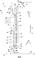
- FIG. 2 is a schematic, cross-sectional view of the elevator system 10, and in particular illustrates a cooling system 20 of the elevator car 14.
- the cooling system 20 is configured to direct air in a manner that cools the electronic visual displays 18.
- the elevator car 14 includes side walls 22 with a shell having a double-walled thickness.
- One of the side walls 22 is shown in Figure 2 . While a double-walled thickness shell including two spaced-apart panels is shown in Figure 2 , this disclosure extends to side walls having a single-walled thickness shell.
- the side walls 22 each have a double-walled thickness shell provided by an inner wall 24 and an outer wall 26 spaced-apart from the inner wall 24 in a horizontal direction by a space 28.
- the space 28 is a substantially hollow space in this example.
- the space 28 may also be at least partially filled with noise attenuating material.
- other noise attenuating features such as baffles may be incorporated into the shell.
- the inner and outer walls 24, 26 are panels, in this example, and extend from a floor 30 of the elevator car 14 to a ceiling 32. Together, the inner walls 24, floor 30, and ceiling 32 define the passenger space 12. Alternatively, there may be decorative panels below the ceiling 32 and/or above the floor 30 which partially define the passenger space 12.
- the electronic visual displays 18 are mounted to the inner walls 24, in this example, by way of mounting brackets 34.
- the mounting brackets 34 are directly attached to both the inner walls 24 and the electronic visual displays 18.
- the electronic visual displays 18 are mounted such that a back surface 36 of the electronic visual displays 18 faces the inner wall 24 and is spaced-apart from the inner wall 24 so as to define a gap 38 between the inner wall 24 and the electronic visual display 18.
- the mounting brackets 34 may include vertical and horizontal bracket components. This disclosure is not limited to any particular type of mounting bracket.
- the electronic visual displays 18 typically generate and emit heat during use.
- This disclosure provides a cooling system 20 configured to cool the electronic visual displays 18.
- fluid is configured to flow through the gap 38 to cool the electronic visual displays 18.
- the fluid is air, in one example, and thus this disclosure may referred to as a forced air cooling system.
- a particular aspect of this disclosure provides two independent fluid flow paths, one of which is configured to direct fluid to cool the passenger space 12 and one of which is configured to direct fluid through the gap 38 to cool the electronic visual displays 18.
- cooling system 20 includes a first flow path through which fluid F 1 is configured to flow to cool the passenger space 12.
- the passenger space 12 is fluidly coupled to a source of fluid F 1 by a first flow path inlet 42 configured to direct fluid F 1 into the passenger space 12 beneath the electronic visual displays 18.
- the first flow path inlet 42 includes a first port 42A in outer wall 26 and a second port 42B in inner wall 24 and arranged vertically beneath the first port 42A.
- the first port 42A is fluidly coupled to air within a hoistway, in one example, and fluid F 1 is configured to flow between the first and second ports 42A, 42B within the space 28.
- the second port 42B is arranged vertically below a bottom-most edge 44 of a bottom one of the electronic visual displays 18 such that fluid F 1 may flow to the passenger space 12.
- the fluid F 1 cools the passenger space 12 by directing hot air out an outlet 46 in the ceiling 32, in this example.
- the outlet 46 is above a top-most edge 48 of a top one of the electronic visual displays 18.
- the outlet 46 does not need to be in the ceiling 32 in all examples, and could be in an upper section of the side wall 22, for example.
- the outlet 46 could include a fan 68 configured to direct fluid out of the passenger space 12, in some examples.
- the cooling system 20 also includes a second flow path through which fluid F 2 is configured to flow to cool the electronic visual displays 18.
- the fluids Fi, F 2 may both be air and may both be sourced from a hoistway.
- the fluids Fi, F 2 may be sourced from locations other than the hoistway, however.
- the fluids are referred to separately herein because they are directed through different flow paths.
- the gap 38 is fluidly coupled to the fluid F 2 by a second flow path inlet 50, which includes a port 50A in the outer wall 26 and a port 50B in the inner wall 24 arranged vertically below the port 50A.
- the second flow path inlet 50 is vertically above the first flow path inlet 42.
- Fluid F 2 is configured to flow in the space 28 between the port 50A and 50B.
- the port 50B is arranged adjacent, and in this example slightly above, the bottom-most edge 44 of the bottom electronic visual display 18. As such, fluid F 2 exiting the port 50B flows vertically upward through the gap 38 and cools the electronic visual displays 18 by directing hot air away from the electronic visual displays 18.
- the fluid F 2 flows vertically upward toward a second flow path outlet 52, which includes port 52A in the outer wall 26 and port 52B in the inner wall 24.
- the port 52B is arranged vertically below the port 52A and is arranged adjacent, and in this example slightly below, the upper-most edge 48 of the upper electronic visual display 18.
- the second flow path outlet 52 is vertically below the first flow path outlet 46.
- the side wall 22 includes two partitions, in this example, to prevent mixing of the various flows of fluid.
- a first partition 54 extends horizontally between the inner wall 24 and the outer wall 26 and is arranged below the port 50B to prevent the fluid F 2 from mixing with fluid F 1 .
- a second partition 56 extends horizontally between the inner wall 24 and the outer wall 26 and is arranged above the port 50A to prevent the fluid F 2 adjacent the second flow path inlet 50, which is relatively cooler, from mixing with fluid F 2 adjacent the outlet 52, which is relatively hotter.
- the partitions 54, 56 divide the side wall 22 into three vertical sections in this example.
- the first section provides first flow path inlet 42 and extends from the floor 30 to the first partition 54, which is at about knee height of an average-height passenger.
- the second section provides the second flow path inlet 50 and extends vertically between the first partition 54 and the second partition 56, which is at about waist height.
- the third section provides the second flow path outlet 52 and extends from the second partition 56 to the ceiling 32.
- the flow of fluid F 2 is established (i.e., introduced) within the second flow path by passively flowing from the second flow path inlet 50 to the second flow path outlet 52 without being forced by a fan.
- the cooling system 20 includes at least one fan (e.g., one at the inlet, one at the outlet, or both) configured to actively establish the flow of fluid F 2 through the second flow path. While fans are illustrated relative to the second flow path, it should be understood that one or more fans (e.g., fan 68) could also be used relative to the first flow path in order to actively establish the flow of fluid F 1 . Alternatively, the flow of fluid F 1 may be established passively.
- the cooling system 20 includes a second flow path inlet fan 58 arranged adjacent the second flow path inlet 50 and configured to direct fluid F 2 into the gap 38.
- the cooling system 20 further includes a second flow path outlet fan 60 arranged adjacent the second flow path outlet 52 and configured to draw, and exhaust, fluid F 2 out of the gap 38.
- the fans 58, 60 are shown schematically in Figure 2 .
- the second flow path inlet fan 58 is mounted in the port 50B and is at least partially arranged in the space 28 between the inner wall 24 and the outer wall 26.
- the second flow path outlet fan 60 is mounted in the port 52B and is at least partially arranged in the space 28.
- the fans 58, 60 are at least partially recessed into the side wall 22.
- the fans 58, 60 may be fully recessed in other examples. In those examples, the fans 58, 60 are completely within the space 28.
- the fans 58, 60 may also be mounted to the outer wall 26 in examples where it is not possible to mount fans to the inner wall 24.
- the fans 58, 60 are electronically connected to a controller 62, and the fans 58, 60 are selectively activated in response to instructions from the controller 62.
- the controller 62 is shown schematically in Figure 2 .
- the controller 62 includes electronics, software, or both, to perform the necessary control functions.
- the controller 62 is an elevator drive controller. Although it is shown as a single device, the controller 62 may include multiple controllers in the form of multiple hardware devices, or multiple software controllers within one or more hardware devices.
- a controller area network (CAN) 64 illustrated schematically, allows the controller 62 to communicate with various components of the elevator system 10 by wired and/or wireless electronic connections.
- the controller 62 is electronically connected to a temperature sensor 66.
- a single temperature sensor 66 is shown.
- the temperature sensor 66 is mounted adjacent one of the electronic visual displays 18 and is configured to generate a signal indicative of a temperature of the electronic visual displays 18. Additional temperature sensors may be mounted to other electronic visual displays 18.
- the temperature sensor 66 may alternatively be mounted adjacent the passenger space 12 and be configured to generate a signal indicative of a temperature of the passenger space 12.
- the controller 62 is configured to selectively activate the fans 58, 60 in response to the signal(s) from the temperature sensor(s). In another example, there are no temperature sensors, and instead the controller 62 activates the fans 58, 60 when the electronic visual displays 18 are activated (i.e., turned on).
- the controller 62 may also independently activate a fan 68 arranged in outlet 46 based on information from one or more of the temperature sensors, for example.
- the elevator system 10 may include a plurality of electronic visual displays 18.
- the electronic visual displays 18 may be arranged in vertical sets, with each vertical set including a plurality of electronic visual displays arranged vertically one over the other.
- Figure 2 illustrates one such vertical set, and thus includes one second flow path.
- the cooling system 20 may include additional second flow paths.
- the cooling system 20 may include one second flow path, substantially similar to the one shown in Figure 2 , arranged adjacent each vertical set of electronic visual displays.
- the additional fans may be electronically connected in series (i.e., daisy chained) in order to reduce bulky electrical harnesses.
- the cooling system 20 may further include various seals and partitions configured to keep the fluid F 2 within the gap 38 and prevent mixing of the fluids F 1 , F 2 .
- the seals and partitions may extend between adjacent electronic visual displays 18, between the inner wall 24 and the electronic visual displays, etc.
- the seals and partitions may be provided in part by the mounting brackets 34, various gaskets, and/or other structures such as baffles.
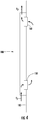
- Figures 3 and 4 illustrate another aspect of the present disclosure.
- Figures 3 and 4 illustrate an elevator car 114 similar to the elevator car 14 with like reference numerals pre-appended with a "1."
- Figures 3 and 4 do not show any electronic visual displays, although they would be arranged similar to the previous embodiment.
- Figure 3 and 4 also only show the second flow path. It should be understood that the first flow path would be arranged similarly to the embodiment of Figure 2 .
- the elevator car 114 includes a single-thickness shell side wall 122.
- the outer surface 182 in this example faces the hoistway.
- the baffle 180 allows fluid such as the fluid F 2 to enter and exit at the axial ends of the baffle 180.
- the baffle 180 covers fans 158 and 160 and provides protection relative to the fans similar to that which is provided by the outer wall 26 in the previously discussed embodiment.
- the baffle 180 also attenuates noise and permits fluid to flow in a desired direction. While only one baffle 180 is illustrated in Figures 3 and 4 , the side wall 122 may incorporate a number of similarly-arranged baffles. Further, the baffle 180 may be used in the embodiment of Figure 2 to attenuate noise and cover the inlets and/or outlets 42, 50, 52.
- the baffle 180 may be used when retrofitting existing elevator cars with a system as described herein.
Landscapes
- Engineering & Computer Science (AREA)
- Civil Engineering (AREA)
- Mechanical Engineering (AREA)
- Structural Engineering (AREA)
- Automation & Control Theory (AREA)
- Physics & Mathematics (AREA)
- Thermal Sciences (AREA)
- Microelectronics & Electronic Packaging (AREA)
- Indicating And Signalling Devices For Elevators (AREA)
- Cage And Drive Apparatuses For Elevators (AREA)
Abstract
Description
- This disclosure relates to a cooling system for an elevator with electronic visual displays, and a corresponding method.
- Elevator cars are known to include electronic visual displays, which may be configured to display still images or videos to passengers. More recently, in buildings with destination landings, such as upper floor restaurants or observation decks, such electronic visual displays are used to display information about the building and/or the observation deck while the elevator car transports passengers to and from the observation deck.
- A system according to an exemplary aspect of the present disclosure includes, among other things, an elevator car having an inner wall, and an electronic visual display mounted to the inner wall so as to define a gap between the inner wall and the electronic visual display. Further, fluid is configured to flow through the gap to cool the electronic visual display.
- In a further non-limiting embodiment of the foregoing system, the system includes a first flow path through which fluid is configured to flow to cool a passenger space, and a second flow path through which fluid is configured to flow to cool the electronic visual display.
- In a further non-limiting embodiment of any of the foregoing systems, the system includes a plurality of sets of electronic visual displays and further includes a plurality of second flow paths, and each of the second flow paths is arranged adjacent to a respective one of the sets of electronic visual displays.
- In a further non-limiting embodiment of any of the foregoing systems, each set of electronic visual displays includes a first electronic visual display mounted vertically above a second electronic visual display.
- In a further non-limiting embodiment of any of the foregoing systems, the passenger space is interior of the sets of electronic visual displays.
- In a further non-limiting embodiment of any of the foregoing systems, the passenger space is fluidly coupled to a source of fluid by a first flow path inlet configured to direct fluid into the passenger space beneath the electronic visual display, and the passenger space is fluidly coupled to a location outside the elevator car by a first flow path outlet arranged above the electronic visual display.
- In a further non-limiting embodiment of any of the foregoing systems, the gap is fluidly coupled to a source of fluid by a second flow path inlet arranged adjacent a bottom of the electronic visual display, and the gap is fluidly coupled to a location outside the elevator car by a second flow path outlet arranged adjacent a top of the electronic visual display.
- In a further non-limiting embodiment of any of the foregoing systems, the second flow path inlet is vertically above the first flow path inlet.
- In a further non-limiting embodiment of any of the foregoing systems, the second flow path outlet is vertically below the first flow path outlet.
- In a further non-limiting embodiment of any of the foregoing systems, the system includes a second flow path inlet fan arranged adjacent the second flow path inlet and configured to direct fluid to the gap, and a second flow path outlet fan arranged adjacent the second flow path outlet and configured to draw fluid out of the gap.
- In a further non-limiting embodiment of any of the foregoing systems, the elevator car includes a double-walled thickness including the inner wall and an outer wall spaced-apart from the inner wall, the second flow path inlet fan is at least partially arranged in a space between the inner wall and the outer wall, and the second flow path outlet fan is at least partially arranged in the space between the inner wall and the outer wall.
- In a further non-limiting embodiment of any of the foregoing systems, the system includes a temperature sensor configured to generate a signal indicative of a temperature of one of the electronic visual display and the passenger space, and a controller configured to selectively activate the second flow path inlet fan and the second flow path outlet fan in response to the signal.
- In a further non-limiting embodiment of any of the foregoing systems, the system includes a controller configured to selectively activate the second flow path inlet fan and the second flow path outlet fan when the electronic visual display is activated.
- In a further non-limiting embodiment of any of the foregoing systems, the elevator car is in a building with an observation deck, and the electronic visual display is a screen configured to present at least one of images and video pertaining to the observation deck.
- A method according to an exemplary aspect of the present disclosure includes, among other things, establishing a flow of fluid within a gap between an inner wall of an elevator car and an electronic visual display mounted to the inner wall.
- In a further non-limiting embodiment of the foregoing method, the method includes establishing a flow of fluid into a passenger space of the elevator car independent of the flow of fluid within the gap.
- In a further non-limiting embodiment of any of the foregoing methods, the step of establishing a flow of fluid within the gap includes directing the fluid into the gap using an inlet fan.
- In a further non-limiting embodiment of any of the foregoing methods, the method includes drawing air out of the gap using an outlet fan.
- In a further non-limiting embodiment of any of the foregoing methods, the method includes activating the inlet fan and the outlet fan in response to a signal from a temperature sensor.
- In a further non-limiting embodiment of any of the foregoing methods, the method includes activating the inlet fan and the outlet fan when the electronic visual display is activated.
- The embodiments, examples and alternatives of the preceding paragraphs, the claims, or the following description and drawings, including any of their various aspects or respective individual features, may be taken independently or in any combination. Features described in connection with one embodiment are applicable to all embodiments, unless such features are incompatible.
-
-
Figure 1 illustrates a portion of a passenger space of an example elevator car. -
Figure 2 schematically illustrates a cooling system of the elevator car. -
Figure 3 is a somewhat schematic, perspective view of a side wall of another example elevator car. -
Figure 4 is a somewhat schematic cross-sectional view taken along line 4-4 inFigure 3 . - This disclosure relates to a cooling system for an elevator with electronic visual displays, and a corresponding method. An example system includes an elevator car having an inner wall, and an electronic visual display mounted to the inner wall so as to define a gap between the inner wall and the electronic visual display. Further, fluid is configured to flow through the gap to cool the electronic visual display. Among other benefits, which will be appreciated from the below description, this disclosure provides effective cooling for electronic visual displays within elevator cars, without being unduly large or expensive, and without drawing high power during operation. The system also simplifies maintenance and is scalable in terms of the number of fans, the size of the elevator car, and/or the number of electronic visual displays within the elevator car. Further, the system is low-noise and produces minimal, if any, condensation.
-
Figure 1 illustrates anexample elevator system 10, and in particular illustrates a portion of a passenger space 12 (i.e., passenger cabin) of anelevator car 14. Theelevator system 10, in this example, is located in a building with a destination landing, such as an upper floor restaurant or an observation deck. In the example, theelevator car 14 is configured to travel within a hoistway to transportpassengers 16 to and from a lobby of the building and the observation deck. While observation decks are mentioned herein, this disclosure is not limited to elevator systems used in buildings with observation decks, and extends to other elevator systems with electronic visual displays including those intended to provide passengers with an immersive media experience. - In the example of
Figure 1 , a plurality ofpassengers 16 are traveling between a lobby and an observation deck. Theelevator car 14, in this example, includes a plurality of electronicvisual displays 18. The electronicvisual displays 18 are arranged relative to one another such that, collectively, the electronic visual displays 18 substantially cover the entirety of the inner walls of theelevator car 14. As such, the electronicvisual displays 18 can provide thepassengers 16 with an immersive media experience. While a plurality of electronic visual displays are shown inFigure 1 , it should be understood that this disclosure extends to elevator cars with one or more electronic visual displays. Further, while electronicvisual displays 18 are shown on three different walls of theelevator car 14 inFigure 1 , this disclosure extends to elevator systems with at least one electronic visual display on at least one wall of an elevator car. The disclosure separately applies to elevator systems with one or more electronic visual displays on a ceiling of the elevator car. - In one example, the electronic visual displays 18 display information about the observation deck to the
passengers 16 as they are transported to or from the observation deck. For instance, the electronicvisual displays 18 can be used to display an informative video to thepassengers 16. The video may include information about the observation deck such as the height of the observation deck, current weather, visibility, visible landmarks, history of the building, and other information. This disclosure is not limited to electronic visual display that play videos that pertain to observation decks, however. The electronicvisual displays 18 could display other content such as still images, videos, advertisements, etc. The electronicvisual displays 18 could present other types of media. -
Figure 2 is a schematic, cross-sectional view of theelevator system 10, and in particular illustrates acooling system 20 of theelevator car 14. In this disclosure, thecooling system 20 is configured to direct air in a manner that cools the electronicvisual displays 18. - The
elevator car 14 includesside walls 22 with a shell having a double-walled thickness. One of theside walls 22 is shown inFigure 2 . While a double-walled thickness shell including two spaced-apart panels is shown inFigure 2 , this disclosure extends to side walls having a single-walled thickness shell. - In particular, the
side walls 22 each have a double-walled thickness shell provided by aninner wall 24 and anouter wall 26 spaced-apart from theinner wall 24 in a horizontal direction by aspace 28. Thespace 28 is a substantially hollow space in this example. Thespace 28 may also be at least partially filled with noise attenuating material. In the example of a single-walled thickness shell, other noise attenuating features such as baffles may be incorporated into the shell. - The inner and
outer walls floor 30 of theelevator car 14 to aceiling 32. Together, theinner walls 24,floor 30, andceiling 32 define thepassenger space 12. Alternatively, there may be decorative panels below theceiling 32 and/or above thefloor 30 which partially define thepassenger space 12. - The electronic
visual displays 18 are mounted to theinner walls 24, in this example, by way of mountingbrackets 34. The mountingbrackets 34 are directly attached to both theinner walls 24 and the electronic visual displays 18. The electronicvisual displays 18 are mounted such that aback surface 36 of the electronicvisual displays 18 faces theinner wall 24 and is spaced-apart from theinner wall 24 so as to define agap 38 between theinner wall 24 and the electronicvisual display 18. InFigure 2 , there are two electronicvisual displays 18, with one mounted vertically above another to provide a vertical set of electronic visual displays. While two electronicvisual displays 18 are shown vertically arranged relative to one another herein, it should be understood that other electronic visual display arrangements are contemplated by this disclosure. For instance, the two electronicvisual displays 18 could be replaced with a single, relatively taller electronic visual display. Alternatively, there could be three or more vertically stacked electronic visual displays 18. - Front surfaces 40 of the electronic
visual displays 18, which include a screen, face toward the center of theelevator car 14. The mountingbrackets 34 may include vertical and horizontal bracket components. This disclosure is not limited to any particular type of mounting bracket. - The electronic
visual displays 18 typically generate and emit heat during use. This disclosure provides acooling system 20 configured to cool the electronic visual displays 18. In a particular embodiment, fluid is configured to flow through thegap 38 to cool the electronic visual displays 18. The fluid is air, in one example, and thus this disclosure may referred to as a forced air cooling system. As will be appreciated from the below, a particular aspect of this disclosure provides two independent fluid flow paths, one of which is configured to direct fluid to cool thepassenger space 12 and one of which is configured to direct fluid through thegap 38 to cool the electronic visual displays 18. - Specifically, cooling
system 20 includes a first flow path through which fluid F1 is configured to flow to cool thepassenger space 12. In particular, thepassenger space 12 is fluidly coupled to a source of fluid F1 by a firstflow path inlet 42 configured to direct fluid F1 into thepassenger space 12 beneath the electronic visual displays 18. The firstflow path inlet 42 includes afirst port 42A inouter wall 26 and asecond port 42B ininner wall 24 and arranged vertically beneath thefirst port 42A. Thefirst port 42A is fluidly coupled to air within a hoistway, in one example, and fluid F1 is configured to flow between the first andsecond ports space 28. Thesecond port 42B is arranged vertically below abottom-most edge 44 of a bottom one of the electronicvisual displays 18 such that fluid F1 may flow to thepassenger space 12. The fluid F1 cools thepassenger space 12 by directing hot air out anoutlet 46 in theceiling 32, in this example. Theoutlet 46 is above atop-most edge 48 of a top one of the electronic visual displays 18. Theoutlet 46 does not need to be in theceiling 32 in all examples, and could be in an upper section of theside wall 22, for example. Theoutlet 46 could include afan 68 configured to direct fluid out of thepassenger space 12, in some examples. - The
cooling system 20 also includes a second flow path through which fluid F2 is configured to flow to cool the electronic visual displays 18. The fluids Fi, F2 may both be air and may both be sourced from a hoistway. The fluids Fi, F2 may be sourced from locations other than the hoistway, however. The fluids are referred to separately herein because they are directed through different flow paths. - The
gap 38 is fluidly coupled to the fluid F2 by a secondflow path inlet 50, which includes aport 50A in theouter wall 26 and aport 50B in theinner wall 24 arranged vertically below theport 50A. The secondflow path inlet 50 is vertically above the firstflow path inlet 42. Fluid F2 is configured to flow in thespace 28 between theport port 50B is arranged adjacent, and in this example slightly above, thebottom-most edge 44 of the bottom electronicvisual display 18. As such, fluid F2 exiting theport 50B flows vertically upward through thegap 38 and cools the electronicvisual displays 18 by directing hot air away from the electronic visual displays 18. - The fluid F2 flows vertically upward toward a second
flow path outlet 52, which includesport 52A in theouter wall 26 andport 52B in theinner wall 24. Theport 52B is arranged vertically below theport 52A and is arranged adjacent, and in this example slightly below, theupper-most edge 48 of the upper electronicvisual display 18. The secondflow path outlet 52 is vertically below the firstflow path outlet 46. - The
side wall 22 includes two partitions, in this example, to prevent mixing of the various flows of fluid. Afirst partition 54 extends horizontally between theinner wall 24 and theouter wall 26 and is arranged below theport 50B to prevent the fluid F2 from mixing with fluid F1. A second partition 56 extends horizontally between theinner wall 24 and theouter wall 26 and is arranged above theport 50A to prevent the fluid F2 adjacent the secondflow path inlet 50, which is relatively cooler, from mixing with fluid F2 adjacent theoutlet 52, which is relatively hotter. - The
partitions 54, 56 divide theside wall 22 into three vertical sections in this example. The first section provides firstflow path inlet 42 and extends from thefloor 30 to thefirst partition 54, which is at about knee height of an average-height passenger. The second section provides the secondflow path inlet 50 and extends vertically between thefirst partition 54 and the second partition 56, which is at about waist height. The third section provides the secondflow path outlet 52 and extends from the second partition 56 to theceiling 32. - In one example, the flow of fluid F2 is established (i.e., introduced) within the second flow path by passively flowing from the second
flow path inlet 50 to the secondflow path outlet 52 without being forced by a fan. In another example, thecooling system 20 includes at least one fan (e.g., one at the inlet, one at the outlet, or both) configured to actively establish the flow of fluid F2 through the second flow path. While fans are illustrated relative to the second flow path, it should be understood that one or more fans (e.g., fan 68) could also be used relative to the first flow path in order to actively establish the flow of fluid F1. Alternatively, the flow of fluid F1 may be established passively. - In the example of
Figure 2 , thecooling system 20 includes a second flow path inlet fan 58 arranged adjacent the secondflow path inlet 50 and configured to direct fluid F2 into thegap 38. Thecooling system 20 further includes a second flowpath outlet fan 60 arranged adjacent the secondflow path outlet 52 and configured to draw, and exhaust, fluid F2 out of thegap 38. Thefans 58, 60 are shown schematically inFigure 2 . In this example, the second flow path inlet fan 58 is mounted in theport 50B and is at least partially arranged in thespace 28 between theinner wall 24 and theouter wall 26. The second flowpath outlet fan 60 is mounted in theport 52B and is at least partially arranged in thespace 28. Thus, thefans 58, 60 are at least partially recessed into theside wall 22. Thefans 58, 60 may be fully recessed in other examples. In those examples, thefans 58, 60 are completely within thespace 28. Thefans 58, 60 may also be mounted to theouter wall 26 in examples where it is not possible to mount fans to theinner wall 24. - The
fans 58, 60 are electronically connected to acontroller 62, and thefans 58, 60 are selectively activated in response to instructions from thecontroller 62. Thecontroller 62 is shown schematically inFigure 2 . Thecontroller 62 includes electronics, software, or both, to perform the necessary control functions. In one non-limiting embodiment, thecontroller 62 is an elevator drive controller. Although it is shown as a single device, thecontroller 62 may include multiple controllers in the form of multiple hardware devices, or multiple software controllers within one or more hardware devices. A controller area network (CAN) 64, illustrated schematically, allows thecontroller 62 to communicate with various components of theelevator system 10 by wired and/or wireless electronic connections. - In one aspect of this disclosure, the
controller 62 is electronically connected to atemperature sensor 66. InFigure 2 , asingle temperature sensor 66 is shown. Thetemperature sensor 66 is mounted adjacent one of the electronicvisual displays 18 and is configured to generate a signal indicative of a temperature of the electronic visual displays 18. Additional temperature sensors may be mounted to other electronic visual displays 18. Thetemperature sensor 66 may alternatively be mounted adjacent thepassenger space 12 and be configured to generate a signal indicative of a temperature of thepassenger space 12. Thecontroller 62 is configured to selectively activate thefans 58, 60 in response to the signal(s) from the temperature sensor(s). In another example, there are no temperature sensors, and instead thecontroller 62 activates thefans 58, 60 when the electronicvisual displays 18 are activated (i.e., turned on). Thecontroller 62 may also independently activate afan 68 arranged inoutlet 46 based on information from one or more of the temperature sensors, for example. - As mentioned above, the
elevator system 10 may include a plurality of electronic visual displays 18. The electronicvisual displays 18 may be arranged in vertical sets, with each vertical set including a plurality of electronic visual displays arranged vertically one over the other.Figure 2 illustrates one such vertical set, and thus includes one second flow path. It should be understood that thecooling system 20 may include additional second flow paths. Specifically, thecooling system 20 may include one second flow path, substantially similar to the one shown inFigure 2 , arranged adjacent each vertical set of electronic visual displays. When there are additional second flow paths, the additional fans may be electronically connected in series (i.e., daisy chained) in order to reduce bulky electrical harnesses. - The
cooling system 20 may further include various seals and partitions configured to keep the fluid F2 within thegap 38 and prevent mixing of the fluids F1, F2. The seals and partitions may extend between adjacent electronicvisual displays 18, between theinner wall 24 and the electronic visual displays, etc. In one example, the seals and partitions may be provided in part by the mountingbrackets 34, various gaskets, and/or other structures such as baffles. -
Figures 3 and4 illustrate another aspect of the present disclosure.Figures 3 and4 illustrate anelevator car 114 similar to theelevator car 14 with like reference numerals pre-appended with a "1."Figures 3 and4 do not show any electronic visual displays, although they would be arranged similar to the previous embodiment.Figure 3 and4 also only show the second flow path. It should be understood that the first flow path would be arranged similarly to the embodiment ofFigure 2 . - The
elevator car 114 includes a single-thicknessshell side wall 122. InFigure 3 , there is a vertically-arrangedbaffle 180 on anouter surface 182 of theside wall 122. Theouter surface 182 in this example faces the hoistway. Thebaffle 180 allows fluid such as the fluid F2 to enter and exit at the axial ends of thebaffle 180. In this example, thebaffle 180 coversfans outer wall 26 in the previously discussed embodiment. Thebaffle 180 also attenuates noise and permits fluid to flow in a desired direction. While only onebaffle 180 is illustrated inFigures 3 and4 , theside wall 122 may incorporate a number of similarly-arranged baffles. Further, thebaffle 180 may be used in the embodiment ofFigure 2 to attenuate noise and cover the inlets and/oroutlets baffle 180 may be used when retrofitting existing elevator cars with a system as described herein. - It should be understood that terms such as "generally," "substantially," and "about" are not intended to be boundaryless terms, and should be interpreted consistent with the way one skilled in the art would interpret those terms. Further, directional terms such as "vertical," "horizontal," "above," and "below" are used consistent with their plain and ordinary meanings with reference to the normal operational attitude of an elevator car and should not otherwise be considered limiting.
- Although the different examples have the specific components shown in the illustrations, embodiments of this disclosure are not limited to those particular combinations. It is possible to use some of the components or features from one of the examples in combination with features or components from another one of the examples. In addition, the various figures accompanying this disclosure are not necessarily to scale, and some features may be exaggerated or minimized to show certain details of a particular component or arrangement.
- One of ordinary skill in this art would understand that the above-described embodiments are exemplary and non-limiting. That is, modifications of this disclosure would come within the scope of the claims. Accordingly, the following claims should be studied to determine their true scope and content.
Claims (15)
- A system, comprising:an elevator car having an inner wall; andan electronic visual display mounted to the inner wall so as to define a gap between the inner wall and the electronic visual display, wherein fluid is configured to flow through the gap to cool the electronic visual display.
- The system as recited in claim 1, further comprising:a first flow path through which fluid is configured to flow to cool a passenger space; anda second flow path through which fluid is configured to flow to cool the electronic visual display.
- The system as recited in claim 2, wherein:the system includes a plurality of sets of electronic visual displays and further includes a plurality of second flow paths, andeach of the second flow paths is arranged adjacent to a respective one of the sets of electronic visual displays.
- The system as recited in claim 3, wherein each set of electronic visual displays includes a first electronic visual display mounted vertically above a second electronic visual display and/or wherein the passenger space is interior of the sets of electronic visual displays.
- The system as recited in any one of claim 2, 3, or 4, wherein:the passenger space is fluidly coupled to a source of fluid by a first flow path inlet configured to direct fluid into the passenger space beneath the electronic visual display, andthe passenger space is fluidly coupled to a location outside the elevator car by a first flow path outlet arranged above the electronic visual display.
- The system as recited in claim 5, wherein:the gap is fluidly coupled to a source of fluid by a second flow path inlet arranged adjacent a bottom of the electronic visual display, andthe gap is fluidly coupled to a location outside the elevator car by a second flow path outlet arranged adjacent a top of the electronic visual display.
- The system as recited in claim 6, wherein the second flow path inlet is vertically above the first flow path inlet and/or wherein the second flow path outlet is vertically below the first flow path outlet.
- The system as recited in any one of claims 5, 6 or 7, further comprising:a second flow path inlet fan arranged adjacent the second flow path inlet and configured to direct fluid to the gap; anda second flow path outlet fan arranged adjacent the second flow path outlet and configured to draw fluid out of the gap.
- The system as recited in claim 8, wherein:the elevator car includes a double-walled thickness including the inner wall and an outer wall spaced-apart from the inner wall,the second flow path inlet fan is at least partially arranged in a space between the inner wall and the outer wall, andthe second flow path outlet fan is at least partially arranged in the space between the inner wall and the outer wall.
- The system as recited in claim 8 or 9, further comprising:a temperature sensor configured to generate a signal indicative of a temperature of one of the electronic visual display and the passenger space; anda controller configured to selectively activate the second flow path inlet fan and the second flow path outlet fan in response to the signal.
- The system as recited in any one of claims 8, 9 or 10, further comprising:
a controller configured to selectively activate the second flow path inlet fan and the second flow path outlet fan when the electronic visual display is activated. - The system as recited in any preceding claim, wherein:the elevator car is in a building with an observation deck, andthe electronic visual display is a screen configured to present at least one of images and video pertaining to the observation deck.
- A method, comprising:
establishing a flow of fluid within a gap between an inner wall of an elevator car and an electronic visual display mounted to the inner wall. - The method as recited in claim 13, further comprising establishing a flow of fluid into a passenger space of the elevator car independent of the flow of fluid within the gap and/or wherein the step of establishing a flow of fluid within the gap includes directing the fluid into the gap using an inlet fan.
- The method as recited in claim 14, further comprising drawing air out of the gap using an outlet fan and optionally further comprising:activating the inlet fan and the outlet fan in response to a signal from a temperature sensor; and/oractivating the inlet fan and the outlet fan when the electronic visual display is activated.
Applications Claiming Priority (1)
| Application Number | Priority Date | Filing Date | Title |
|---|---|---|---|
| US16/592,813 US11267675B2 (en) | 2019-10-04 | 2019-10-04 | Cooling system for elevator with electronic visual displays |
Publications (2)
| Publication Number | Publication Date |
|---|---|
| EP3800156A1 true EP3800156A1 (en) | 2021-04-07 |
| EP3800156B1 EP3800156B1 (en) | 2025-03-05 |
Family
ID=72709149
Family Applications (1)
| Application Number | Title | Priority Date | Filing Date |
|---|---|---|---|
| EP20199338.3A Active EP3800156B1 (en) | 2019-10-04 | 2020-09-30 | Cooling system for elevator car electronic visual displays and method thereof |
Country Status (3)
| Country | Link |
|---|---|
| US (1) | US11267675B2 (en) |
| EP (1) | EP3800156B1 (en) |
| CN (1) | CN112607560B (en) |
Families Citing this family (2)
| Publication number | Priority date | Publication date | Assignee | Title |
|---|---|---|---|---|
| US11267675B2 (en) * | 2019-10-04 | 2022-03-08 | Otis Elevator Company | Cooling system for elevator with electronic visual displays |
| KR102217759B1 (en) * | 2020-08-12 | 2021-02-22 | 주식회사 다지트 | Display device, elevator assembly including the same and method for image processing |
Citations (6)
| Publication number | Priority date | Publication date | Assignee | Title |
|---|---|---|---|---|
| US2350389A (en) * | 1940-10-07 | 1944-06-06 | Tyler Co W S | Method of and apparatus for ventilating elevator cars |
| KR20120055910A (en) * | 2010-11-24 | 2012-06-01 | 윤일식 | Heat Radiating and Fixing Device for a Display Panel of an Elevator |
| WO2015030435A1 (en) * | 2013-08-26 | 2015-03-05 | Yoon Il Shik | Display device provided on elevator cage wall surface |
| KR20150031664A (en) * | 2013-09-16 | 2015-03-25 | 윤일식 | Display Device Mounted on a Wall Side of an Elevator Cage |
| KR20160029413A (en) * | 2014-09-05 | 2016-03-15 | 주식회사 다지트 | Ventilation Device for a Display of an Elevator Hall Door |
| EP3064462A1 (en) * | 2013-10-28 | 2016-09-07 | Dajit | Ventilating apparatus for display of elevator hall door |
Family Cites Families (22)
| Publication number | Priority date | Publication date | Assignee | Title |
|---|---|---|---|---|
| JPH08113449A (en) * | 1994-10-17 | 1996-05-07 | Mitsubishi Electric Corp | Light source for elevator car floor |
| JP2000103581A (en) * | 1998-09-29 | 2000-04-11 | Otis Elevator Co | Elevator cage |
| JP2003076286A (en) * | 2001-09-06 | 2003-03-14 | Ngk Insulators Ltd | Cooling system for display device |
| KR100598406B1 (en) * | 2004-11-17 | 2006-07-07 | 삼성전자주식회사 | Display device |
| US8235777B2 (en) * | 2005-05-03 | 2012-08-07 | Daniel Stanimirovic | Fully articulated and comprehensive air and fluid distribution, metering and control method and apparatus for primary movers, heat exchangers, and terminal flow devices |
| EP1962029A2 (en) * | 2007-02-23 | 2008-08-27 | Sharp Kabushiki Kaisha | Wall assembly and a hot-water supply system |
| US8872379B2 (en) * | 2007-11-30 | 2014-10-28 | Johnson Controls Technology Company | Efficient usage, storage, and sharing of energy in buildings, vehicles, and equipment |
| EP2312384B1 (en) * | 2008-07-09 | 2014-09-10 | NEC Corporation | Liquid crystal display device |
| JP5241416B2 (en) * | 2008-09-30 | 2013-07-17 | 三洋電機株式会社 | Image display device |
| EP2530044A1 (en) * | 2011-05-30 | 2012-12-05 | Inventio AG | Lift shaft cover with a lift control assembly |
| WO2013183108A1 (en) * | 2012-06-04 | 2013-12-12 | 株式会社Pfu | Information processing device, method, and program |
| KR102099693B1 (en) * | 2013-03-14 | 2020-05-15 | 7에이씨 테크놀로지스, 아이엔씨. | Methods and systems for mini-split liquid desiccant air conditioning |
| KR101334452B1 (en) * | 2013-07-29 | 2013-11-29 | 윤일식 | Monitor system of elevator door |
| JPWO2016121028A1 (en) * | 2015-01-28 | 2017-11-02 | Necディスプレイソリューションズ株式会社 | COOLING DEVICE, PROJECTION DISPLAY DEVICE, AND COOLING METHOD |
| WO2016138962A1 (en) * | 2015-03-05 | 2016-09-09 | Otis Elevator Company | Elevator car |
| WO2016207478A1 (en) * | 2015-06-26 | 2016-12-29 | Kone Corporation | Content information of floor of elevator |
| AU2016231519A1 (en) * | 2015-09-22 | 2017-04-06 | Coates Technology Labs Pty Limited | Display housing for a digital display screen |
| EP3309107A1 (en) * | 2016-10-17 | 2018-04-18 | Otis Elevator Company | Elevator doorway display systems for elevator cars |
| US20190056127A1 (en) * | 2017-08-18 | 2019-02-21 | Otis Elevator Company | Enclosed space air conditioning systems |
| US10502890B2 (en) * | 2017-12-29 | 2019-12-10 | Huizhou China Star Optoelectronics Technology Co., Ltd. | Display device and wall-mounted heat dissipation mechanism thereof |
| KR102117578B1 (en) * | 2019-01-25 | 2020-06-09 | 엘지전자 주식회사 | Display apparatus |
| US11267675B2 (en) * | 2019-10-04 | 2022-03-08 | Otis Elevator Company | Cooling system for elevator with electronic visual displays |
-
2019
- 2019-10-04 US US16/592,813 patent/US11267675B2/en active Active
-
2020
- 2020-09-29 CN CN202011049780.0A patent/CN112607560B/en active Active
- 2020-09-30 EP EP20199338.3A patent/EP3800156B1/en active Active
Patent Citations (6)
| Publication number | Priority date | Publication date | Assignee | Title |
|---|---|---|---|---|
| US2350389A (en) * | 1940-10-07 | 1944-06-06 | Tyler Co W S | Method of and apparatus for ventilating elevator cars |
| KR20120055910A (en) * | 2010-11-24 | 2012-06-01 | 윤일식 | Heat Radiating and Fixing Device for a Display Panel of an Elevator |
| WO2015030435A1 (en) * | 2013-08-26 | 2015-03-05 | Yoon Il Shik | Display device provided on elevator cage wall surface |
| KR20150031664A (en) * | 2013-09-16 | 2015-03-25 | 윤일식 | Display Device Mounted on a Wall Side of an Elevator Cage |
| EP3064462A1 (en) * | 2013-10-28 | 2016-09-07 | Dajit | Ventilating apparatus for display of elevator hall door |
| KR20160029413A (en) * | 2014-09-05 | 2016-03-15 | 주식회사 다지트 | Ventilation Device for a Display of an Elevator Hall Door |
Also Published As
| Publication number | Publication date |
|---|---|
| US11267675B2 (en) | 2022-03-08 |
| CN112607560B (en) | 2022-10-04 |
| CN112607560A (en) | 2021-04-06 |
| EP3800156B1 (en) | 2025-03-05 |
| US20210101780A1 (en) | 2021-04-08 |
Similar Documents
| Publication | Publication Date | Title |
|---|---|---|
| EP3800156B1 (en) | Cooling system for elevator car electronic visual displays and method thereof | |
| EP2671801B1 (en) | Environmental control system and methods of operating same | |
| EP0594882B1 (en) | Ventilating apparatus for conveyance | |
| CN102771202B (en) | Data center air route system | |
| US7486511B1 (en) | Passive rear door for controlled hot air exhaust | |
| US20090275277A1 (en) | Alternate directional momentum ventilation nozzle for passenger cabins | |
| EP2931605B1 (en) | Aircraft circulation system for passenger cabins | |
| GB2382872A (en) | Under floor air cooled housing system for aircraft passenger seat electronic units | |
| HK144194A (en) | Air conditioning system for fast-moving elevator cabins | |
| US10392113B2 (en) | Galley cooling system and method of operating a galley cooling system | |
| JP6121161B2 (en) | Vehicle air conditioning system and railway vehicle equipped with the same | |
| JP2010044692A (en) | Air conditioning system | |
| JP4531598B2 (en) | Railway vehicle | |
| US20140339001A1 (en) | Cab, and work vehicle | |
| GB2568308A (en) | A vehicle ventilation system | |
| CN104085767A (en) | Monitor system for elevator door | |
| JP2018002418A (en) | Elevator car | |
| JP7618454B2 (en) | Vehicle compartment ventilation system | |
| CN100366483C (en) | ventilation system for vehicle | |
| JP5474028B2 (en) | Air conditioning equipment and vehicles | |
| SE465182B (en) | Installation for supplying fresh air to a room and cooling the room air by circulation via a cooling device | |
| WO2017115491A1 (en) | Liquified gas carrier | |
| WO2020230548A1 (en) | Vehicular air-conditioning device | |
| JP2006007901A (en) | Railway vehicle | |
| JP2017013912A (en) | Elevator air-conditioning suction/discharge structure |
Legal Events
| Date | Code | Title | Description |
|---|---|---|---|
| PUAI | Public reference made under article 153(3) epc to a published international application that has entered the european phase |
Free format text: ORIGINAL CODE: 0009012 |
|
| STAA | Information on the status of an ep patent application or granted ep patent |
Free format text: STATUS: THE APPLICATION HAS BEEN PUBLISHED |
|
| AK | Designated contracting states |
Kind code of ref document: A1 Designated state(s): AL AT BE BG CH CY CZ DE DK EE ES FI FR GB GR HR HU IE IS IT LI LT LU LV MC MK MT NL NO PL PT RO RS SE SI SK SM TR |
|
| AX | Request for extension of the european patent |
Extension state: BA ME |
|
| STAA | Information on the status of an ep patent application or granted ep patent |
Free format text: STATUS: REQUEST FOR EXAMINATION WAS MADE |
|
| 17P | Request for examination filed |
Effective date: 20211007 |
|
| RBV | Designated contracting states (corrected) |
Designated state(s): AL AT BE BG CH CY CZ DE DK EE ES FI FR GB GR HR HU IE IS IT LI LT LU LV MC MK MT NL NO PL PT RO RS SE SI SK SM TR |
|
| STAA | Information on the status of an ep patent application or granted ep patent |
Free format text: STATUS: EXAMINATION IS IN PROGRESS |
|
| 17Q | First examination report despatched |
Effective date: 20220908 |
|
| GRAP | Despatch of communication of intention to grant a patent |
Free format text: ORIGINAL CODE: EPIDOSNIGR1 |
|
| STAA | Information on the status of an ep patent application or granted ep patent |
Free format text: STATUS: GRANT OF PATENT IS INTENDED |
|
| INTG | Intention to grant announced |
Effective date: 20240416 |
|
| GRAJ | Information related to disapproval of communication of intention to grant by the applicant or resumption of examination proceedings by the epo deleted |
Free format text: ORIGINAL CODE: EPIDOSDIGR1 |
|
| STAA | Information on the status of an ep patent application or granted ep patent |
Free format text: STATUS: EXAMINATION IS IN PROGRESS |
|
| GRAP | Despatch of communication of intention to grant a patent |
Free format text: ORIGINAL CODE: EPIDOSNIGR1 |
|
| STAA | Information on the status of an ep patent application or granted ep patent |
Free format text: STATUS: GRANT OF PATENT IS INTENDED |
|
| GRAJ | Information related to disapproval of communication of intention to grant by the applicant or resumption of examination proceedings by the epo deleted |
Free format text: ORIGINAL CODE: EPIDOSDIGR1 |
|
| STAA | Information on the status of an ep patent application or granted ep patent |
Free format text: STATUS: EXAMINATION IS IN PROGRESS |
|
| GRAP | Despatch of communication of intention to grant a patent |
Free format text: ORIGINAL CODE: EPIDOSNIGR1 |
|
| INTC | Intention to grant announced (deleted) | ||
| STAA | Information on the status of an ep patent application or granted ep patent |
Free format text: STATUS: GRANT OF PATENT IS INTENDED |
|
| INTG | Intention to grant announced |
Effective date: 20240913 |
|
| INTC | Intention to grant announced (deleted) | ||
| INTG | Intention to grant announced |
Effective date: 20240926 |
|
| GRAS | Grant fee paid |
Free format text: ORIGINAL CODE: EPIDOSNIGR3 |
|
| GRAA | (expected) grant |
Free format text: ORIGINAL CODE: 0009210 |
|
| STAA | Information on the status of an ep patent application or granted ep patent |
Free format text: STATUS: THE PATENT HAS BEEN GRANTED |
|
| AK | Designated contracting states |
Kind code of ref document: B1 Designated state(s): AL AT BE BG CH CY CZ DE DK EE ES FI FR GB GR HR HU IE IS IT LI LT LU LV MC MK MT NL NO PL PT RO RS SE SI SK SM TR |
|
| REG | Reference to a national code |
Ref country code: GB Ref legal event code: FG4D |
|
| REG | Reference to a national code |
Ref country code: CH Ref legal event code: EP |
|
| REG | Reference to a national code |
Ref country code: IE Ref legal event code: FG4D |
|
| REG | Reference to a national code |
Ref country code: DE Ref legal event code: R096 Ref document number: 602020047107 Country of ref document: DE |
|
| PG25 | Lapsed in a contracting state [announced via postgrant information from national office to epo] |
Ref country code: RS Free format text: LAPSE BECAUSE OF FAILURE TO SUBMIT A TRANSLATION OF THE DESCRIPTION OR TO PAY THE FEE WITHIN THE PRESCRIBED TIME-LIMIT Effective date: 20250605 |
|
| PG25 | Lapsed in a contracting state [announced via postgrant information from national office to epo] |
Ref country code: FI Free format text: LAPSE BECAUSE OF FAILURE TO SUBMIT A TRANSLATION OF THE DESCRIPTION OR TO PAY THE FEE WITHIN THE PRESCRIBED TIME-LIMIT Effective date: 20250305 |
|
| REG | Reference to a national code |
Ref country code: NL Ref legal event code: MP Effective date: 20250305 |
|
| PG25 | Lapsed in a contracting state [announced via postgrant information from national office to epo] |
Ref country code: ES Free format text: LAPSE BECAUSE OF FAILURE TO SUBMIT A TRANSLATION OF THE DESCRIPTION OR TO PAY THE FEE WITHIN THE PRESCRIBED TIME-LIMIT Effective date: 20250305 |
|
| REG | Reference to a national code |
Ref country code: LT Ref legal event code: MG9D |
|
| PG25 | Lapsed in a contracting state [announced via postgrant information from national office to epo] |
Ref country code: NO Free format text: LAPSE BECAUSE OF FAILURE TO SUBMIT A TRANSLATION OF THE DESCRIPTION OR TO PAY THE FEE WITHIN THE PRESCRIBED TIME-LIMIT Effective date: 20250605 |
|
| PG25 | Lapsed in a contracting state [announced via postgrant information from national office to epo] |
Ref country code: HR Free format text: LAPSE BECAUSE OF FAILURE TO SUBMIT A TRANSLATION OF THE DESCRIPTION OR TO PAY THE FEE WITHIN THE PRESCRIBED TIME-LIMIT Effective date: 20250305 |
|
| PG25 | Lapsed in a contracting state [announced via postgrant information from national office to epo] |
Ref country code: LV Free format text: LAPSE BECAUSE OF FAILURE TO SUBMIT A TRANSLATION OF THE DESCRIPTION OR TO PAY THE FEE WITHIN THE PRESCRIBED TIME-LIMIT Effective date: 20250305 |
|
| PG25 | Lapsed in a contracting state [announced via postgrant information from national office to epo] |
Ref country code: GR Free format text: LAPSE BECAUSE OF FAILURE TO SUBMIT A TRANSLATION OF THE DESCRIPTION OR TO PAY THE FEE WITHIN THE PRESCRIBED TIME-LIMIT Effective date: 20250606 Ref country code: BG Free format text: LAPSE BECAUSE OF FAILURE TO SUBMIT A TRANSLATION OF THE DESCRIPTION OR TO PAY THE FEE WITHIN THE PRESCRIBED TIME-LIMIT Effective date: 20250305 |
|
| REG | Reference to a national code |
Ref country code: AT Ref legal event code: MK05 Ref document number: 1772821 Country of ref document: AT Kind code of ref document: T Effective date: 20250305 |
|
| PG25 | Lapsed in a contracting state [announced via postgrant information from national office to epo] |
Ref country code: NL Free format text: LAPSE BECAUSE OF FAILURE TO SUBMIT A TRANSLATION OF THE DESCRIPTION OR TO PAY THE FEE WITHIN THE PRESCRIBED TIME-LIMIT Effective date: 20250305 |
|
| PG25 | Lapsed in a contracting state [announced via postgrant information from national office to epo] |
Ref country code: SE Free format text: LAPSE BECAUSE OF FAILURE TO SUBMIT A TRANSLATION OF THE DESCRIPTION OR TO PAY THE FEE WITHIN THE PRESCRIBED TIME-LIMIT Effective date: 20250305 |
|
| PG25 | Lapsed in a contracting state [announced via postgrant information from national office to epo] |
Ref country code: SM Free format text: LAPSE BECAUSE OF FAILURE TO SUBMIT A TRANSLATION OF THE DESCRIPTION OR TO PAY THE FEE WITHIN THE PRESCRIBED TIME-LIMIT Effective date: 20250305 |
|
| PG25 | Lapsed in a contracting state [announced via postgrant information from national office to epo] |
Ref country code: PT Free format text: LAPSE BECAUSE OF FAILURE TO SUBMIT A TRANSLATION OF THE DESCRIPTION OR TO PAY THE FEE WITHIN THE PRESCRIBED TIME-LIMIT Effective date: 20250707 |
|
| PGFP | Annual fee paid to national office [announced via postgrant information from national office to epo] |
Ref country code: DE Payment date: 20250820 Year of fee payment: 6 |
|
| PG25 | Lapsed in a contracting state [announced via postgrant information from national office to epo] |
Ref country code: PL Free format text: LAPSE BECAUSE OF FAILURE TO SUBMIT A TRANSLATION OF THE DESCRIPTION OR TO PAY THE FEE WITHIN THE PRESCRIBED TIME-LIMIT Effective date: 20250305 Ref country code: IT Free format text: LAPSE BECAUSE OF FAILURE TO SUBMIT A TRANSLATION OF THE DESCRIPTION OR TO PAY THE FEE WITHIN THE PRESCRIBED TIME-LIMIT Effective date: 20250305 |
|
| PG25 | Lapsed in a contracting state [announced via postgrant information from national office to epo] |
Ref country code: AT Free format text: LAPSE BECAUSE OF FAILURE TO SUBMIT A TRANSLATION OF THE DESCRIPTION OR TO PAY THE FEE WITHIN THE PRESCRIBED TIME-LIMIT Effective date: 20250305 |
|
| PGFP | Annual fee paid to national office [announced via postgrant information from national office to epo] |
Ref country code: FR Payment date: 20250821 Year of fee payment: 6 |
|
| PG25 | Lapsed in a contracting state [announced via postgrant information from national office to epo] |
Ref country code: CZ Free format text: LAPSE BECAUSE OF FAILURE TO SUBMIT A TRANSLATION OF THE DESCRIPTION OR TO PAY THE FEE WITHIN THE PRESCRIBED TIME-LIMIT Effective date: 20250305 Ref country code: EE Free format text: LAPSE BECAUSE OF FAILURE TO SUBMIT A TRANSLATION OF THE DESCRIPTION OR TO PAY THE FEE WITHIN THE PRESCRIBED TIME-LIMIT Effective date: 20250305 |
|
| PG25 | Lapsed in a contracting state [announced via postgrant information from national office to epo] |
Ref country code: RO Free format text: LAPSE BECAUSE OF FAILURE TO SUBMIT A TRANSLATION OF THE DESCRIPTION OR TO PAY THE FEE WITHIN THE PRESCRIBED TIME-LIMIT Effective date: 20250305 |
|
| PG25 | Lapsed in a contracting state [announced via postgrant information from national office to epo] |
Ref country code: SK Free format text: LAPSE BECAUSE OF FAILURE TO SUBMIT A TRANSLATION OF THE DESCRIPTION OR TO PAY THE FEE WITHIN THE PRESCRIBED TIME-LIMIT Effective date: 20250305 |
|
| PG25 | Lapsed in a contracting state [announced via postgrant information from national office to epo] |
Ref country code: IS Free format text: LAPSE BECAUSE OF FAILURE TO SUBMIT A TRANSLATION OF THE DESCRIPTION OR TO PAY THE FEE WITHIN THE PRESCRIBED TIME-LIMIT Effective date: 20250705 |
|
| REG | Reference to a national code |
Ref country code: DE Ref legal event code: R097 Ref document number: 602020047107 Country of ref document: DE |
|
| PLBE | No opposition filed within time limit |
Free format text: ORIGINAL CODE: 0009261 |
|
| STAA | Information on the status of an ep patent application or granted ep patent |
Free format text: STATUS: NO OPPOSITION FILED WITHIN TIME LIMIT |
|
| PG25 | Lapsed in a contracting state [announced via postgrant information from national office to epo] |
Ref country code: DK Free format text: LAPSE BECAUSE OF FAILURE TO SUBMIT A TRANSLATION OF THE DESCRIPTION OR TO PAY THE FEE WITHIN THE PRESCRIBED TIME-LIMIT Effective date: 20250305 |
|
| REG | Reference to a national code |
Ref country code: CH Ref legal event code: L10 Free format text: ST27 STATUS EVENT CODE: U-0-0-L10-L00 (AS PROVIDED BY THE NATIONAL OFFICE) Effective date: 20260114 |
|
| 26N | No opposition filed |
Effective date: 20251208 |
|
| REG | Reference to a national code |
Ref country code: CH Ref legal event code: H13 Free format text: ST27 STATUS EVENT CODE: U-0-0-H10-H13 (AS PROVIDED BY THE NATIONAL OFFICE) Effective date: 20260425 |