EP3800138A1 - Packaging for an attachable unit for a smoking article - Google Patents
Packaging for an attachable unit for a smoking article Download PDFInfo
- Publication number
- EP3800138A1 EP3800138A1 EP20205213.0A EP20205213A EP3800138A1 EP 3800138 A1 EP3800138 A1 EP 3800138A1 EP 20205213 A EP20205213 A EP 20205213A EP 3800138 A1 EP3800138 A1 EP 3800138A1
- Authority
- EP
- European Patent Office
- Prior art keywords
- panel
- tray
- attachable unit
- smoking article
- sleeve portion
- Prior art date
- Legal status (The legal status is an assumption and is not a legal conclusion. Google has not performed a legal analysis and makes no representation as to the accuracy of the status listed.)
- Withdrawn
Links
Images




Classifications
-
- A—HUMAN NECESSITIES
- A24—TOBACCO; CIGARS; CIGARETTES; SIMULATED SMOKING DEVICES; SMOKERS' REQUISITES
- A24F—SMOKERS' REQUISITES; MATCH BOXES; SIMULATED SMOKING DEVICES
- A24F47/00—Smokers' requisites not otherwise provided for
-
- B—PERFORMING OPERATIONS; TRANSPORTING
- B65—CONVEYING; PACKING; STORING; HANDLING THIN OR FILAMENTARY MATERIAL
- B65D—CONTAINERS FOR STORAGE OR TRANSPORT OF ARTICLES OR MATERIALS, e.g. BAGS, BARRELS, BOTTLES, BOXES, CANS, CARTONS, CRATES, DRUMS, JARS, TANKS, HOPPERS, FORWARDING CONTAINERS; ACCESSORIES, CLOSURES, OR FITTINGS THEREFOR; PACKAGING ELEMENTS; PACKAGES
- B65D5/00—Rigid or semi-rigid containers of polygonal cross-section, e.g. boxes, cartons or trays, formed by folding or erecting one or more blanks made of paper
- B65D5/38—Drawer-and-shell type containers
-
- B—PERFORMING OPERATIONS; TRANSPORTING
- B65—CONVEYING; PACKING; STORING; HANDLING THIN OR FILAMENTARY MATERIAL
- B65D—CONTAINERS FOR STORAGE OR TRANSPORT OF ARTICLES OR MATERIALS, e.g. BAGS, BARRELS, BOTTLES, BOXES, CANS, CARTONS, CRATES, DRUMS, JARS, TANKS, HOPPERS, FORWARDING CONTAINERS; ACCESSORIES, CLOSURES, OR FITTINGS THEREFOR; PACKAGING ELEMENTS; PACKAGES
- B65D5/00—Rigid or semi-rigid containers of polygonal cross-section, e.g. boxes, cartons or trays, formed by folding or erecting one or more blanks made of paper
- B65D5/42—Details of containers or of foldable or erectable container blanks
- B65D5/44—Integral, inserted or attached portions forming internal or external fittings
- B65D5/50—Internal supporting or protecting elements for contents
- B65D5/5028—Elements formed separately from the container body
- B65D5/5035—Paper elements
- B65D5/5038—Tray-like elements formed by folding a blank and presenting openings or recesses
-
- B—PERFORMING OPERATIONS; TRANSPORTING
- B65—CONVEYING; PACKING; STORING; HANDLING THIN OR FILAMENTARY MATERIAL
- B65D—CONTAINERS FOR STORAGE OR TRANSPORT OF ARTICLES OR MATERIALS, e.g. BAGS, BARRELS, BOTTLES, BOXES, CANS, CARTONS, CRATES, DRUMS, JARS, TANKS, HOPPERS, FORWARDING CONTAINERS; ACCESSORIES, CLOSURES, OR FITTINGS THEREFOR; PACKAGING ELEMENTS; PACKAGES
- B65D85/00—Containers, packaging elements or packages, specially adapted for particular articles or materials
- B65D85/07—Containers, packaging elements or packages, specially adapted for particular articles or materials for compressible or flexible articles
- B65D85/08—Containers, packaging elements or packages, specially adapted for particular articles or materials for compressible or flexible articles rod-shaped or tubular
Definitions
- the invention relates to packaging for an attachable unit for a smoking article, an arrangement of one or more blanks for forming the same, and a kit including said packaging and a plurality of smoking article rods.
- Cigarettes and other smoking articles produce an aerosol, smoke in the case of cigarettes, which is inhaled by a user.
- Separate filter units may be attached to smoking articles to modify the aerosol before it reaches the user's mouth.
- packaging for an attachable unit for a smoking article comprising a receptacle or receiver in which the attachable unit is receivable and a gripping mechanism to releasably hold the attachable unit within the receptacle or receiver when the attachable unit is received in the receptacle or receiver.
- the packaging can further comprise a sleeve portion and a tray slidable within the sleeve portion, wherein the tray comprises the gripping mechanism and the receptacle or receiver.
- the receptacle or receiver can comprise a receiving aperture which is at least partially defined by a recess or cut-out formed in an upper panel of the tray.
- the upper panel can be arranged to be disposed parallel to a base panel of the tray when the attachable unit is received in the receptacle or receiver.
- the upper panel can be arranged to be disposed nonparallel to a base panel of the tray the attachable unit is received in the receptacle or receiver.
- the tray can comprise a plurality of side panels.
- the gripping mechanism can comprise at least one of the side panels. Said at least one side panel can be at least partially resiliently displaceable to provide a biasing force, in use, on an attachable unit when received in the receptacle or receiver.
- each of the side panels can have a height which is less than a height of a side panel of the sleeve portion.
- the sleeve portion can comprise an upper panel
- the tray can further comprise a base panel and a guide member configured to provide a reactive force against the sleeve portion to keep the base panel of the tray substantially parallel to the upper panel of the sleeve as the tray is slid within the sleeve portion.
- the receptacle or receiver can comprise a receiving aperture and the gripping mechanism can comprise a tab that depends from an edge of the receiving aperture for engagement with an attachable unit received therein.
- the tab can be at least partially resiliently displaceable.
- the tab can be formed from material forming a panel in which the receptacle is formed.
- the tab can be formed from material within the periphery of the receiving aperture.
- the packaging can comprise between one and six tabs for each receiving aperture, or can comprise 4 tabs for each receiving aperture.
- the gripping mechanism can comprise an adhesive.
- packaging for an attachable unit for a smoking article comprising a receiver to receive the attachable unit in a predetermined position and a guide disposed relative to the receiver to align the smoking article with the attachable unit when the attachable unit is received by the receiver such that the attachable unit can be attached to the smoking article.
- the receiver can be formed in a first sheet material lying in a first plane and the guide can be formed in a second sheet material lying in a second plane spaced from said first plane.
- the first plane can be parallel to the second plane.
- the receiver and guide can be circular apertures centred on a common axis.
- the common axis can be perpendicular to the first and/or second planes.
- the second plane can be spaced from said first plane by a distance of between 5mm and 50mm or between 10mm and 25mm or between 15mm and 20mm.
- the packaging can comprise an outer container comprising a first panel in which the guide is formed.
- the packaging can comprise an inner panel held within the outer container, wherein the receiver is formed in the inner panel.
- the outer container can comprise a second panel spaced from said first panel and the inner panel can be provided between the first and second panels and can be spaced a predetermined distance from the first and second panels.
- the predetermined distance of the inner panel from the first panel can be between 5mm and 30mm and the predetermined distance of the inner panel from the second panel can be between 3mm and 15mm.
- the packaging can further comprise a sleeve, wherein the outer container is slideably received in the sleeve to provide access to the receiver and guide.
- the packaging can further comprise a plurality of receivers, wherein the receiver comprises one of the plurality of receivers.
- the packaging can further comprise a plurality of guides, wherein the guide comprises one of the plurality of guides, and wherein each respective guide is arranged to align the smoking article with a respective attachable unit when the respective attachable unit is received by a respective receiver such that the respective attachable unit can be attached to the smoking article.
- the plurality of guides and the plurality of receivers can each be provided in a respective array.
- the packaging can comprise an adhesive patch applied to an outer surface of the packaging to enable the packaging to be attached to an object or surface.
- the or each receiver can comprise a receptacle
- the packaging can further comprise a gripping mechanism associated with the or each receptacle to releasably hold an attachable unit within the or each receptacle.
- the or each receptacle can comprise a receiving aperture and the gripping mechanism can comprise a tab that depends from an edge of the or each receiving aperture for engagement with an attachable unit received therein.
- the tab can be at least partially resiliently displaceable.
- the tab can be formed from material forming a or the panel in which the receiving aperture is formed.
- the tab can be formed from material within the periphery of the receiving aperture.
- the packaging can comprise between one and six tabs for each receiving aperture, or can comprise 4 tabs for each receiving aperture.
- the gripping mechanism can comprises an adhesive.
- the packaging can further comprise a resealable cover flap that extends over the or each guide.
- the guide can comprise an inner edge of an aligning aperture formed in the packaging.
- packaging according to embodiments of the invention as set out above comprising an attachable unit for a smoking article received within the or each receiver, the attachable unit to be attached to a smoking article rod by a user to modify an aerosol generated by the smoking article rod.
- kits comprising packaging according to embodiments of the invention as set out above, and a plurality of smoking article rods.
- smoking article includes combustible smoking articles such as cigarettes, cigars and cigarillos whether based on tobacco, tobacco derivatives, expanded tobacco, reconstituted tobacco or tobacco substitutes and also heating devices such as heat-not-burn (HnB) devices, which release compounds from substrate materials, such as tobacco, without burning the substrate material, and other nicotine delivery products such as aerosol generation devices including e-cigarettes.
- the smoking article may be provided with a filter for the gaseous flow drawn by the smoker.
- Smoking articles such as cigarettes and their formats are often named according to the cigarette length: "regular” (typically in the range 68 - 75 mm, e.g. from about 68 mm to about 72 mm), “short” or “mini” (68 mm or less), “king-size” (typically in the range 75 - 91 mm, e.g. from about 79 mm to about 88 mm), “long” or “super-king” (typically in the range 91 - 105 mm, e.g. from about 94 mm to about 101 mm) and “ultra-long” (typically in the range from about 110 mm to about 121 mm).
- regular typically in the range 68 - 75 mm, e.g. from about 68 mm to about 72 mm
- mini 68 mm or less
- king-size typically in the range 75 - 91 mm, e.g. from about 79 mm to about 88 mm
- a cigarette in a king-size, super-slim format will, for example, have a length of about 83 mm and a circumference of about 17 mm.
- Cigarettes in the regular, king-size format are preferred by many customers, namely with a circumference of from 23 to 25 mm and an overall length of from 75 to 91 mm.
- Each format may be produced with filters of different lengths, smaller filters being generally used in formats of smaller lengths and circumferences.
- the filter length will be from about 15 mm, associated with short, regular formats, to 30 mm, associated with ultra-long super-slim formats.
- the tipping paper will have a greater length than the filter, for example from 3 to 10 mm longer, such that the tipping paper covers the filter and overlaps the tobacco rod to connect the filter to the tobacco rod.
- Smoking articles described herein can be made in, but are not limited to, any of the above formats.
- Figure 1 is a side-on cross sectional view of a first example of an attachable unit 3 and a smoking article rod 2 which can be coupled together by a user to form a smoking article 100.
- the attachable unit 3 is configured to modify one or more properties of an aerosol generated by the smoking article rod 2.
- the attachable unit 3 comprises a recess 30 into which at least a portion of the smoking article rod 2 can be received when the attachable unit 3 is coupled to the smoking article rod 2.
- the attachable unit 3 comprises a cylindrical element 21 which is surrounded by a sheet material 22 forming a sleeve around the cylindrical element 21.
- the cylindrical element 21 comprises filter material, in the present case cellulose acetate tow, circumferentially wrapped in the sheet material 22, although the attachable unit 3 can be formed in other ways.
- the sheet material 22 comprises stiff paper.
- the attachable unit is arranged such that the smoking article rod 2 and attachable unit 3 are aligned on a longitudinal axis when the attachable unit 3 is coupled to the smoking article rod 2.
- the cylindrical element 21 comprises first and second longitudinal ends 23, 24, which, in the present example are exposed, allowing smoke or other aerosols to pass longitudinally through the cylindrical element 21.
- the sheet material 22 extends longitudinally beyond the first longitudinal end surface 23 of the cylindrical element 21.
- the recess 30 is formed by the first longitudinal end surface 23 of the cylindrical element 21 together with the inner surface of the portion of the sheet material 22 which extends longitudinally beyond the first longitudinal end surface 23 of the cylindrical element 21.
- the sheet material 22 extends up to the second longitudinal end surface 24 of the cylindrical element 21, although can alternatively extend beyond the second longitudinal end surface 24, forming a further recess (not shown), or can be arranged to stop short of the longitudinal end surface 24, such that the sheet material 22 does not surround the full length of the cylindrical element 21.
- the smoking article rod 2 shown in Figure 1 has a tobacco rod 4 longitudinally connected, end-on, to a filter 6.
- An external end surface 16 of the filter 6 at the end opposite to the end of the filter 6 facing the tobacco rod 4 defines a mouth end surface 16 of the smoking article rod 2.
- the smoking article rod 2 can be a conventional smoking article, such as a cigarette.
- the tobacco rod 4 is wrapped in a wrapping material 5, in this case cigarette paper.
- the filter 6 is, in the present example, formed from cellulose acetate tow wrapped in a plug wrap 9.
- the tobacco rod 4 and filter 6 are connected by a tipping material 14 overlaying the filter 6 and partially overlaying the wrapping material 5.
- the filter 6 may comprise two or more filter sections forming the filter 6, which can be connected together using a further plug wrap (not shown), prior to connection of the filter 6 to the tobacco rod 4 using the tipping material 14.
- the smoking article 100 can be provided to users with the attachable unit 3 and smoking article rod 2 as separate components, for instance packaged separately.
- the attachable unit 3 Prior to a user first using the smoking article rod 2, the attachable unit 3 can be attached to the smoking article rod 2 by inserting the mouth-end 16 of the smoking article rod 2 into the recess 30 of the attachable unit 3.
- the attachable unit 3 When the attachable unit 3 is coupled to the smoking article rod 2, the first longitudinal end surface 23 of the cylindrical element 21 abuts the mouth end surface 16 of the filter 6 of the smoking article rod 2.
- the user can select whether or not to attach the attachable unit 3 to the smoking article rod 2 prior to smoking the smoking article 100, and can in this way control the length of filter of the smoking article 100 and therefore the level of filtration of the aerosol generated by the smoking article rod 2.
- the attachable unit 3 can also include additives for modifying the aerosol, in the present case smoke, generated by the smoking article rod 2.
- a capsule containing a flavour additive (not shown) is located within the cylindrical element 21.
- the capsule has a liquid centre and a frangible outer shell which can be broken by a user by squeezing the attachable unit 3, to thereby release the flavour additive.
- the flavour additive is transferred to the aerosol generated by the smoking article rod 2 as the smoking article 100 is smoked.
- the attachable unit 3 may include alternative additives for modifying the aerosol generated by the smoking article rod 2, such as granules of activated carbon or other adsorbents, humectants, diluents and suchlike.
- Figure 2 is a side-on cross sectional view of a second example of an attachable unit 203 and a smoking article rod 202 which can be coupled to form a smoking article 200.
- the attachable unit 203 is arranged to be coupled to the smoking article rod 202 by a user.
- the smoking article rod 202 in the present example comprises a first recess 13.
- the attachable unit 203 is configured to modify one or more properties of an aerosol generated by the smoking article rod 202.
- the attachable unit 203 includes an element 20 arranged to be inserted at least partially into the first recess 13 of the smoking article rod 202.
- the smoking article rod 202 is a cigarette and includes a tobacco rod 4 wrapped in a wrapping material 5, in this case cigarette paper.
- the smoking article rod 202 includes a filter 206 at its mouth end comprising a first section 7 located at the tobacco rod end of the filter 206.
- the first filter section 7 is, in the present example, formed from cellulose acetate tow wrapped in a first plug wrap 9.
- the filter 6 also includes a second section 10 located downstream of the first section 7 and comprising a tubular element 11 wrapped in a second plug wrap 12.
- the tubular element 11 is, in the present example, open at the mouth end of the smoking article rod 202 and defines the first recess, or cavity, 13 at that end. A mouth end surface 216 of the tubular element 11 is exposed at the mouth end of the smoking article rod 202.
- the tobacco rod 4 and first and second filter sections 7, 10 are connected by a tipping material 14 overlaying the first and second filter sections 7, 10 and partially overlaying the wrapping material 5.
- the first and second filter sections 7, 10, and any other sections forming the filter 206 can be connected together using a further plug wrap (not shown), prior to connection of the filter 206 to the tobacco rod 4 using the tipping material 14.
- the cylindrical element 20 of the attachable unit 203 is wrapped in a plug wrap 26 which is substantially impermeable to air, for instance having a permeability of greater than 50 Coresta Units or greater than 100 Coresta Units.
- the cylindrical element 20 may alternatively be unwrapped.
- the cylindrical element 20 of the attachable unit 203 has adjacent first and second portions 20a, 20b, each extending partially along the length of the cylindrical element 20.
- the first portion 20a of the cylindrical element 20 extends from an insertion end of the cylindrical element 20 to an intermediate position 25 along the length of the cylindrical element 20.
- the second portion 20b of the cylindrical element 20 extends from a mouth end of the cylindrical element 20 and ends at the intermediate position 25 along the length of the cylindrical element 20.
- the cylindrical element 20 is 25mm in length and the intermediate position 25 is 12.5mm along the length of the cylindrical element 20 from the insertion end.
- the first portion 20a of the cylindrical element 20 is arranged to be inserted, by a user, into the recess 13 at the mouth end of the smoking article rod 302.
- the attachable unit 203 further comprises an annular element 27 which is arranged around the periphery of the second portion 20b of the cylindrical element 20.
- the annular element 27 has a larger external diameter than the internal diameter of the recess 13.
- the longitudinal end surface 29 of the annular element 27 is arranged to face the smoking article rod 202 when the attachable unit 203 is coupled to the smoking article rod 202.
- the longitudinal end surface 29 may abut the mouth end surface 216 of the tubular element 11 when the attachable unit 203 is attached to the smoking article rod 202, as described below.
- a longitudinal end surface 29' of the cylindrical element 20 may abut a mouth end surface 17 of the first filter section 7 when the attachable unit 203 is attached to the smoking article rod 202.
- the first portion 20a of the cylindrical element 20 is arranged to be inserted into the first recess 13 in the smoking article rod 202, in the present case into the recess 13 formed by the tube section 11.
- the internal diameter and/or length of the recess 13 and the external diameter and/or length of the first portion 20a of the cylindrical element 20 are arranged to substantially correspond such that the first portion 20a of the cylindrical element 20 can be received within and substantially fill the recess 13.
- the internal diameter of the recess 13 can be substantially the same as the external diameter of the first portion 20a of the cylindrical element 20.
- the length of the recess 13 can be substantially the same as the length of the first portion 20a of the cylindrical element 20 protruding proud of the annular element 27.
- the correspondence between the dimensions of the recess 13 and those of the first portion 20a of the cylindrical element 20 will depend on the materials used to form these components and the desired closeness of the fit between them. It is likely to be preferable that the recess dimensions are slightly larger than the dimensions of the first portion 20a, to facilitate insertion of the cylindrical element 20 into the recess 13.
- the recess 13 has an internal diameter of 4mm and the cylindrical element 20 has an external diameter of 3.8mm.
- the internal diameter of the recess 13 and external diameter of the cylindrical element 20 can have other values, for instance diameters in the range from 2mm to 6mm.
- the recess 13 has an internal length of 12mm and the first portion 20a of the cylindrical element 20 has a length of 12mm.
- the internal length of the recess 13 and the length of the first portion 20a of the cylindrical element 20 can have other values, for instance values in the range from 5mm to 20mm.
- the annular element 27 is attached to the cylindrical element 20 using an adhesive (not shown).
- the annular element 27 may be attached to the cylindrical element 20 by means other than an adhesive, for example by mechanical means such as a friction fit or other locking arrangement.
- the attachable unit 203 can include additives for modifying the aerosol, in the present case smoke, generated by the smoking article rod 202, in the same way as the attachable unit 3 described with reference to Figure 1 above.
- the smoking article 200 can be provided to users with the attachable unit 203 and smoking article rod 202 as separate components.
- the attachable unit 203 Prior to a user first using the smoking article rod 202, the attachable unit 203 can be attached to the smoking article rod 202 by inserting the first portion 20a of the cylindrical element 20 into the recess 13.
- the longitudinal end surface 29 of the annular element 27 may abut the end surface 216 of the tubular element 11.
- the user can select whether or not to attach the attachable unit 203 to the smoking article rod 202 prior to smoking the smoking article 200, and can in this way control the length of filter of the smoking article 200 and therefore the level of filtration of the aerosol generated by the smoking article 200, as well as other properties of the aerosol in the case that the attachable unit 203 includes one or more additives for modifying the aerosol.
- Figure 3 is a perspective illustration of packaging 300 for attachable units for smoking articles according to a first example.
- the packaging 300 is configured to receive attachable units 3, 203 of the first or second attachable unit examples described with reference to Figures 1 and 2 , or other such attachable units for smoking articles.
- Figure 4 is a cross sectional view of the packaging illustrated in Figure 3 , through the line A-A' thereof.
- the packaging 300 includes a body portion 301 and a lid portion 302 hingedly connected to the body portion 301.
- the body portion 301 is substantially cuboid in shape.
- the body portion 301 includes an outer container 303 and a body portion insert 304.
- the outer container 303 comprises a first panel 303a, a second panel 303b, and side panels 303c extending between the first and second panels 303a, 303b.
- the body portion insert 304 includes receivers 305, in the present example receiving apertures 305, in which attachable units as described herein are receivable. Other forms of receptacle for attachable units can be used.
- the receiving apertures are also referred to as retaining or holding apertures.
- the receivers need not be formed as the receptacles or receiving apertures described herein, but could comprise an adhesive applied to a panel or other supporting arrangement for receiving attachable units.
- the receiving apertures 305 are illustrated having the attachable units 203 of the second attachable unit example received therein.
- the body portion 301 also includes guides 306, in the present case aligning apertures 306, also referred to as guiding apertures.
- the aligning apertures 306 are provided in the first panel 303a of the outer container 303.
- An inner edge of the guiding aperture is used to align a smoking article rod with a receiver, receptacle or receiving aperture, as will be described in more detail below.
- the aligning apertures 306 are each aligned with a respective receiving aperture 305, and accordingly with a respective attachable unit received in the receiving aperture, so that, when an attachable unit 3, 203 is received in a receiving aperture 305 and a smoking article rod is inserted through a corresponding alignment aperture 306, the smoking article rod is aligned with the attachable unit 3, 203 prior to attachment of the attachable unit 3, 203 to the smoking article rod. This facilitates attachment of the attachable unit 3, 203 to the smoking article rod, while protecting the attachable units 3, 203 within the body portion 301.
- the aligning apertures 306 accordingly have a size and shape configured such that a smoking article rod for use with the attachable units 3, 203 can be inserted through the aligning apertures 306 while being guided by the inner edges of the aligning apertures 306.
- the receiving apertures 305 are dimensioned to receive attachable units 3, 203, and arranged such that the end of a respective attachable unit 3, 203 to which the smoking article rod is to be attached and received in a receiving aperture 305 faces a corresponding respective aligning aperture 306.
- the body portion insert 304 includes an insert panel 304a in which the receiving apertures 305 are formed, supporting members 304b at the sides thereof for supporting the insert panel 304a at a predetermined height above the second panel 303b of the outer container 303, and side panels 304c.
- the body portion insert 304 comprises a gripping mechanism 307 to releasably hold an attachable unit 3, 203 within the receiving aperture 305.
- the gripping mechanism 307 comprises a plurality of tabs 308 that depend from an edge of each receiving aperture 305 for engagement with an attachable unit 3, 203 received therein.
- the gripping mechanism 307 can comprise a single tab for each receiving aperture 305, and/or other mechanisms such as an adhesive.
- Each tab 308 is at least partially resiliently displaceable and accordingly resiliently deforms when an attachable unit is inserted into the receiving aperture 305 producing a biasing force on the attachable unit 3, 203.
- the tabs 308 are formed from sheet material cut from the insert panel 304a in which the receiving apertures 305 are formed.
- the tabs 308 are formed from sheet material cut from within the periphery of the receiving apertures 305, with uncut connecting regions maintaining the attachment of the tabs 308 to the edge of the retaining apertures 305. For instance, four such tabs can be formed by cuts dividing the sheet material within each retaining aperture 305 into four portions.
- the gripping mechanism 307 can be provided in other ways, for instance as an adhesive such as an adhesive patch which could, for instance, be provided on an inner surface of the second panel 303b of the outer container 303.
- adhesive could be provided around the edge of the receiving apertures 305 to form the gripping mechanism 307.
- the first panel 303a can be provided with a resealable cover flap (not shown) that extends over each of the aligning apertures 306.
- the resealable cover flap can have a permanently tacky adhesive on an underside thereof, which forms a seal around the aligning apertures 306.
- the body portion 301 can, in this way, be sealed. This can help to prolong the shelf-life of the attachable units 3, 203 and after first opening of the packaging 300 keep unused attachable units fresh until required for use.
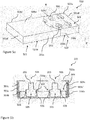
- Figure 5a is a perspective illustration of packaging 500 for attachable units for smoking articles according to a second example.
- Figure 5b is a cross sectional view of the packaging illustrated in Figure 5a , through the line B-B' thereof.
- the packaging 500 of the second example comprises a sleeve portion 501 and a tray 502 arranged to slide within the sleeve portion 501.
- the tray 502 comprises an outer portion 503 and a tray insert 504 received in the outer portion 503.
- the packaging 500 is substantially cuboid in shape.
- the sleeve portion 501 comprises a first panel 501a, a second panel 501b, first and second side panels 501c, 501c', a first end panel 501d (not shown in Figure 5a ) and a second end panel 501d', the side and end panels 501c, 501c', 501d, 501d' extending between the first and second panels 501a, 501b.
- the tray outer portion 503 comprises a first panel 503a, a second panel 503b, first and second side panels 503c, 503c', and first and second end panels 503d, 503d' (the second end panel not shown in Figure 5a ), the side and end panels 503c, 503c', 503d, 503d' extending between the first and second panels 503a, 503b.
- the tray insert 504 includes an insert panel 504a in which receiving apertures 505 are formed, supporting members 504b at the sides thereof for supporting the insert panel 504a at a predetermined height above the second panel 503b of the outer portion 503, and side panels 504c.
- the tray insert 504 therefore includes receiving apertures 505 in which attachable units as described herein are receivable.
- the receiving apertures 505 are illustrated having the attachable units 203 of the second attachable unit example received therein.
- a plurality of receiving apertures 505 are provided in the insert panel 504a of the tray insert 504 and correspond to the receiving apertures 305 described with reference to Figures 3 and 5 .
- the tray outer portion 503 also includes aligning apertures 506.
- the aligning apertures 506 are provided in the first panel 503a of the outer portion 503.
- a plurality of aligning apertures 506 are provided in the first panel 503a of the tray outer portion 503 and correspond to the aligning apertures 306 described with reference to Figures 3 and 5 .
- the aligning apertures 506 are each aligned with a respective receiving aperture 505 and spaced apart from the receiving aperture 505 so that, when an attachable unit 3, 203 is received in a receiving aperture 505 and a smoking article rod is inserted through a corresponding alignment aperture 506, the smoking article rod is aligned with the attachable unit 3, 203 prior to attachable of the attachable unit 3, 203 to the smoking article rod.
- the tray 502 also comprises a gripping mechanism 507 to releasably hold an attachable unit 3, 203 within the receiving aperture 505 when an attachable unit 3, 203 is received in the receiving aperture 505, as described with reference to packaging example 1 and Figures 3 and 4 .
- the gripping mechanism 507 in the present example, is formed by tabs 508 corresponding to the tabs 308 described with reference to packaging example 1 and Figures 3 and 4 .
- the first panel 503a can be provided with a resealable cover flap (not shown) that extends over each of the aligning apertures 506.
- the resealable cover flap can have a permanently tacky adhesive on an underside thereof, which forms a seal around the aligning apertures 506.
- the tray 502 can, in this way, be sealed. This can help to prolong the shelf-life of the attachable units 3, 203 and after first opening of the packaging 500 keep unused attachable units fresh until required for use.
- Blanks for forming the sleeve portion 501, the tray outer portion 503 and the tray insert 504 of the second packaging example are illustrated in Figures 6, 7 and 8 respectively.
- the sleeve portion blank 600 comprises a rectangular panel for forming the first panel 501a separated from a corresponding rectangular panel for forming the second panel 501b.
- Two rectangular panels form each of the first and second side panels 501c, 501c' of the sleeve portion 501, with these overlapping each other when the blank 600 is folded, and two rectangular panels form the second end panel 501d'.
- a single rectangular panel forms the first end panel 501d.
- Tabs 601 are provided with adhesive and attach the panels together when assembling the sleeve portion 501.
- first panel 501a is folded over to lie parallel to the second panel 501b with first end panel 501d disposed perpendicularly in between.
- the first and second side panels 501c, 501c' and second end panel 501d' are formed by overlapping portions of the blank and adhesive can also be applied to these overlapping panels to adhere them together and hold the sleeve portion 501 in shape.
- a cut out 602 and removable portion 603a, 603b, 501d is provided.
- the removable portion 603a, 603b comprises the first end panel 501d and a portion of the first and second panels 501a, 501b delineated by a perforated line of weakening 604.
- the line of weakening encloses a portion of the panel attached to the first end panel 501b.
- the removable portion 603a, 603b, 501d can be separated along the line of weakening to remove the first end panel 501d, forming an opening in the sleeve portion 501 to enable the tray outer portion 502 to slide out of the sleeve portion 501.
- the portions of the first and second panels which are removed allow the user to grip the tray outer portion 502 to slide it from within the sleeve portion 501.
- the cut out 602 enables a user to pull the removable portion 603a, 603b, 501d away from the packaging.
- a blank 700 for the tray outer portion 502 is shown in Figure 7 .
- the tray outer portion 502 is configured to fit within the sleeve portion 501 so that it loosely abuts inner surfaces of the sleeve portion 501 walls to slide easily out of the sleeve portion 501 when required.
- the tray outer portion blank 700 comprises rectangular panels forming the first panel 503a, a second panel 503b, first and second side panels 503c, 503c', and first and second end panels 503d, 503d' of the tray outer portion 503.
- Tabs 701 are provided with adhesive attach the panels together when assembling the tray outer portion 503.
- the blank 700 is assembled in a similar way to the blank 600 forming the sleeve portion 501.
- the first panel 503a of the tray outer portion 503 is provided with an array of aligning apertures 506.
- a '2 by 5' array is shown, though any number of apertures may be provided depending on the size of the packaging and the number of attachable units which are to be stored.
- a blank 800 for forming the tray insert 504 is shown in Figure 8 .
- the insert 504 is configured to fit within the tray outer portion 503.
- the tray insert blank 800 comprises panels for forming the insert panel 504a in which the receiving apertures 505 are formed, supporting members 504b at the sides thereof for supporting the insert panel 504a at a predetermined height above the second panel 503b of the outer portion 503 when the packaging is assembled, and side panels 504c.
- the width 'd' of the rectangular portions forming the supporting members 504b determines the height of the insert panel 504a.
- the supporting member panels 504b are folded perpendicular to the insert panel 504a, and the side panels 504c are folded back onto the supporting member panels 504b to lie parallel to the supporting member panels 504b.
- the tray insert 504 fits within the tray outer portion 503 such that the side panels 504c of the insert 504 abut the first and second side panels 503c, 503c' of the tray outer portion 503. Adhesive maybe applied to the abutting surfaces for additional stability.
- the insert panel 504a of the tray insert 504 is provided with an array of circular receiving apertures 505 aligned to the apertures 506 of the first panel 503a of the tray outer portion 503.
- Figure 9 is a perspective illustration of packaging 900 for attachable units for smoking articles according to a third example.
- the packaging 900 of the third example comprises a sleeve portion 901 and a tray 902 arranged to slide within the sleeve portion 901.
- the sleeve portion 901 comprises a first panel 901a, a second panel 901b, first and second side panels 901c, 901c' a first end panel (not shown in Figure 9 ) and a second end panel 901d', the side and end panels 901c, 901c', 901d, 901d' extending between the first and second panels 901a, 901b.
- the tray 902 is arranged to slide within the sleeve portion 901 and comprises a main body portion 903 which is narrower than the width of the sleeve portion 901 across the width of the first and second panels 901a, 901b, and an end portion 904 which is substantially the width of the sleeve portion 901.
- the main body portion 903 has a first panel 903a, a second panel 903b, and first and second side panels 903c, 903c'.
- the side panels 903c, 903c' are provided with an array of receiving apertures 905 as hereinbefore described, each receiving aperture 905 having a gripping mechanism as hereinbefore described for holding a respective one of the attachable units.
- a space 909 is provided at each side of the main body portion 903 into which attachable units 3, 203 can project when held within the receiving apertures 905.
- An adhesive patch 910 is applied to an outer surface of the packaging to enable the packaging to be attached to an object or surface, for instance to a pack for tobacco industry products such as a cigarette pack.
- the adhesive patch 910 may comprise a protective cover sheet over the adhesive which is removable by a user to expose the adhesive when required.
- Figure 10 is a perspective illustration of packaging 1000 for attachable units for a smoking article according to a fourth example.
- the packaging 1000 of the fourth example comprises a sleeve portion 1001 having a first end 1001' and a second end 1001", and a tray 1002 arranged to slide longitudinally within the sleeve portion 1001.
- the packaging 1000 is arranged so that the tray 1002 can be slid out of the first end 1001' or the second end 1001" of the sleeve portion 1001.
- the packaging 1000 comprises a means for preventing the tray 1002 from being completely removed from the sleeve portion 1001. Such means will be described in more detail below.
- the sleeve portion 1001 comprises a first (or upper) panel 1001a, a second (or base) panel (not shown) and first and second side panels 1001b, 1001c.
- the tray 1002 has a first side panel 1003a and a second side panel 1003b. At least a portion of each of the first and second side panels 1003a, 1003b has a height A which is less than a height B of the sleeve portion 1001, in the present case approximately 50% of the height B of the sleeve portion 1001.
- the height A can be between 20% and 80% of the height B of the sleeve portion 1001, or between 40% and 60% of the height B of the sleeve portion 1001.
- the tray 1002 also has an end panel 1004 which has a height which is substantially the same as the height B of the sleeve portion 1001.
- the first side panel 1003a has a sloping end portion 1003a' sloping from the height of the end panel 1004 to the height A of the portion of the first side panels 1003a.
- the second side panel 1003b has a corresponding sloping end portion 1003b'.
- the tray 1002 also has a base panel (not shown) and an upper panel 1007 extending at least partially across the upper side of the tray 1002.
- the sleeve portion 1001 further comprises first and second cutouts 1008a, 1008b formed in either end of the second side panel 1001c, respectively. Corresponding cutouts (not shown) are formed in the first side panel 1001b. The cutouts allow the user to grip the first and second side panels 1003a, 1003b of the tray 1002 to slide the tray 1002 out from inside the sleeve portion 1001, when the tray 1002 is fully inserted in the sleeve portion 1001.
- the tray 1002 comprises at least one receptacle or receiver, in the present example receiving aperture 1005, and at least one gripping mechanism to releasably hold an attachable unit 3, 203 within the at least one receiving aperture 1005.
- the upper panel 2007 extends only a portion of the way across the upper side of the tray 1002 from second side panel 1003b towards first side panel 1003a and the at least one receiving aperture 1005 is formed as a gap between the upper panel 1007 and a surface at the opposite side of the tray 1002.
- one or more recesses or cut-outs are formed in the upper panel 1007 of the tray 1002, these having a shape corresponding to at least a portion of an attachable unit 3, 203 to be received in the aperture 1005.
- the apertures 1005 are defined between each recess or cut-out and a corresponding opposite side of the tray 1005.
- the opposite side of the tray 1005 comprises one or more tabs 1006, each corresponding to a recess or cut-outs, although the tabs 1006 can be omitted.
- the tray 1002 comprises ten receiving apertures 1005.
- a gripping mechanism is provided for each receiving aperture 1005 and comprises a tab 1006 that extends from an edge of the first side panel 1003a for engagement with an attachable unit 3, 203 received in the receiving aperture.
- the tabs 1006 are semi-circular in shape.
- the gripping mechanism may comprise tabs with different shapes, e.g. squares or triangles.
- the gripping mechanism may comprise other mechanisms such as an adhesive.
- Each tab 1006 is at least partially resiliently displaceable, and accordingly resiliently deforms when an attachable unit 3, 203 as described herein is inserted into a corresponding receiving aperture 1005, thus producing a biasing force on the attachable unit 3, 203.
- the sleeve portion 1001 and the tray 1002 are configured so that when the tray 1002 is inserted in the sleeve portion 1001, there is a space provided above the receiving apertures 1005, into which attachable units 3, 203 can project when held within the receiving apertures 1005.
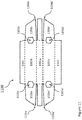
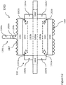
- Blanks for forming the sleeve portion 1001 and the tray 1002 of the fourth packaging example are illustrated in Figures 11 and 12 respectively.
- the sleeve portion blank 1100 comprises a rectangular panel for forming the first panel 1001a of the sleeve portion 1001.
- Two substantially rectangular panels disposed on either side of the rectangular panel form the first and second side panels 1001b, 1001c of the sleeve portion 1001, respectively.
- the first and second side panels 1001b, 1001c are folded towards each other to lie parallel to one another.
- the first panel 1001a is disposed perpendicularly in between the first and second side panels 1001b, 1001c.
- the second panel is formed by overlapping portions 1101, 1102 of the blank 1100, which are disposed perpendicularly to the first and second side panels 1001b, 1001c when the sleeve portion 1001 is formed.
- Two pairs of panels 1103a, 1103a' and 1103b, 1103b' are provided on the blank 1100.
- the panels 1103a, 1103b extend from either side of the panel used to form the first side panel 1001b, while the panels 1103a', 1103b' extend from either side of the panel used to form the second side panel 1001c.
- the two pairs of panels 1103a, 1103a' and 1103b, 1103b' are folded towards each other when forming the sleeve portion 1001 and are disposed inside the sleeve portion 1001, substantially parallel to the first and second side panels 1001b, 1001c.
- Each of the panels 1103a, 1103a', 1103b, 1103b' has a respective tab 1104a, 1104a', 1104b, 1104b'.
- the tabs 1104a, 1104a', 1104b, 1104b' are folded inwardly so as to lie substantially parallel to the respective panels 1103a, 1103a', 1103b, 1103b'.
- tabs 1104a, 1104a', 1104b, 1104b' are configured so as to engage with the respective ends of the sleeve portion.
- tab 1104a engages with end 1003a' in the assembled packaging 1000. This arrangement prevents the tray 1002 from sliding out from the sleeve portion 1001 further than a predetermined amount, which prevents the tray 1002 and sleeve portion 1001 from being unintentionally separated by the user.
- the panels 1103a, 1103a', 1103b, 1103b' and tabs 1104a, 1104a', 1104b, 1104b' are configured so that a maximum of 40% of the length of the tray 1002 can be slid out of the sleeve portion 1001. This arrangement also helps to maintain the strength of the packaging by maintaining at least a 60% overlap of the sleeve portion 1001 and tray 1002 at all times.
- the packaging 1000 is configured so that a maximum of 40% of the length of the tray 1002 can be slid out of the sleeve portion 1001
- alternative configurations maybe used, i.e. so that a different length of the tray 1002 protrudes from the sleeve portion 1001 as a maximum length.
- the packaging 1000 maybe configured so that between 30% and 60% of the length of the tray 1002 can be slid out of the sleeve portion 1001.
- tabs are used to form a means for preventing the tray 1002 from being completely removed from the sleeve portion 1001.
- alternative arrangements such as glue dots or embossed/raised areas of sheet material maybe used, which produce narrower portions within the sleeve portion 1001 and therefore engage with the tray 1002 to limit movement of the tray 1002 within the sleeve portion 1001.
- Cutouts 1105a, 1105a' and 1105b, 1105b' are formed in the blank 1100.
- the cutouts 1105a and 1105b form the cutouts 1108a and 1108b respectively when the blank is assembled into the sleeve portion 1001.
- the tray blank 1200 comprises a substantially rectangular central section 1201 for forming the first and second side panels 1003a, 1003b.
- the central section 1201 comprises a panel 1201a for forming the base panel of the tray 1002.
- the panel 1201a is disposed between the first and second side panels 1003a, 1003b.
- the central section also comprises two panels 1202, 1203 adjacent to the first and second side panels 1003b and 1003a respectively.
- Tabs 1202a and 1202b are formed on the blank 1200 on either side of the panel 1202, and tabs 1203a and 1203b are formed on the blank 1200 on either side of the panel 1203.
- the tabs 1202a and 1202b are folded inwardly to overlap with the second side panel 1003b, and the tabs 1203a and 1203b are folded inwardly to overlap with the first side panel 1003a, in order to strengthen the end portions of the tray 1002.
- Tabs 1004a, 1004b extend from the central section 1201 on either side of the tab used to form the end panel 1004, while tabs 1004a', 1004b' extend from the central section 1201 on either side of the tab used to form the end panel 1004'.
- the tabs 1004a, 1004b and 1004a', 1004b' are folded inwardly when forming the tray 1002, so that the tabs 1004a, 1004b overlap with the end panel 1004 and the tabs 1004a', 1004b' overlap with the end panel 1004'. This arrangement helps to strengthen the end panels 1004, 1004' in the assembled tray 1002.
- the tray blank 1200 further comprises two rectangular sections 1204, 1205 disposed on either side of the central section 1201, adjacent to the panels 1202 and 1203 respectively.
- panel 1203 and section 1205 overlap with the first side panel 1003a
- panel 1202 and section 1204 overlap with the second side panel 1003b, so as to strengthen the first and second side panels 1003a, 1003b.
- the receiving apertures 1005 of the assembled tray 1002 are defined by recesses formed in a panel 1007 adjacent to section 1204, while the tabs 1006 are formed adjacent to section 1205.
- the size and shape of the upper panel 1007 can be configured so that, when one or more attachable units 3, 203 are received in the tray 1002, the panel 1007 is disposed parallel to the base panel of the tray 1002.
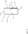
- the size of the upper panel 1007 can be configured so that, when one or more attachable units 3, 203 are received in the tray 1002, the upper panel 1007 extends downwardly in the tray 1002 as it extends away from the second side panel 1003b. This is illustrated in Figure 13 .
- the panel 1007 is disposed nonparallel to the base panel of the tray 1002 and, in the present example, such that it extends away from the second side panel 1003b of the tray 1002 towards the base panel 1201a of the tray 1002 as well as towards the first side panel 1003a of the tray 1002.
- This arrangement can help to restrict the upper panel 1007 from rising and therefore helps to hold the panel 1007 in position when an attachable unit 3, 203 is removed from the tray 1002 in use.
- a central protrusion 1206 is disposed adjacent to the rectangular section 1204.
- the central protrusion 1206 is optional, and may be omitted from the tray blank 1200.
- the blank 1200 is configured so that equal numbers of receiving apertures 1005 are formed on either side of the central protrusion 1206. That is, in the present example, five receiving apertures 1005 are formed on each side of the central protrusion 1206.
- the central protrusion 1206 comprises three parts 1206a, 1206b, 1206c.
- the three parts 1206a, 1206b, 1206c of the central protrusion 1206 are folded so that the central protrusion 1206 forms a guide member (not shown) that extends above the first and second side panels 1003a, 1003b in the assembled tray 1002.
- the guide member is configured to provide a reactive force against the sleeve portion 1001 to keep the base panel of the tray 1002 substantially parallel to the upper panel 1001a of the sleeve portion 1001 as the tray 1002 is moved relative to the sleeve portion 1001.
- the guide member prevents the tray 1002 from being lifted up relative to the sleeve portion 1001.
- the guide member is configured to provide a reactive force against the upper panel 1001a of the sleeve portion 1001.
- the guide member maybe configured to engage with a different part of the sleeve portion 1001.
- the panels 1202, 1203 may be secured to the first and second side panels 1003b, 1003a respectively when assembling the tray 1002. This maybe achieved, for example, by means of an adhesive.
- FIG. 13 A cross-section of the tray 1002 and an attachable unit 3, 203 is shown in Figure 13 .
- the panel 1203 is not secured to the first side panel 1003a, and protrudes inwardly within the tray 1002.
- the gripping mechanism comprises the panel 1203.
- the panel 1203 is at least partially resiliently displaceable, and accordingly resiliently deforms when an attachable unit 3, 203 as described herein is inserted into a corresponding receiving aperture 1005, thus producing a biasing force on the attachable unit 3, 203.
- This arrangement allows the attachable units 3, 203 to be held more securely within the tray 1002.
- the biasing force provided by the panel 1203 is in addition to the biasing force provided by the tabs 1006.
- the tabs 1006 may be omitted from the tray 1002, such that the gripping mechanism comprises only the panel 1203.
- Packaging for an attachable unit for a smoking article comprising:
- Clause 8 Packaging according to Clause 6, wherein said at least one side panel is at least partially resiliently displaceable to provide a biasing force, in use, on an attachable unit when received in the receptacle or receiver.
- Clause 9 Packaging according to any one of Clauses 6 to 8, wherein at least a portion of each of the side panels has a height which is less than a height of a side panel of the sleeve portion.
- Clause 15 Packaging according to any one of Clauses 11 to 14, comprising between one and six tabs for each receiving aperture, or comprising 4 tabs for each receiving aperture.
- Packaging for an attachable unit for a smoking article comprising:
- Clause 20 Packaging according to Clause 18 or 19, wherein the receiver and guide are circular apertures centred on a common axis.
- Clause 22 Packaging according to any one of Clauses 18 to 21, wherein the second plane is spaced from said first plane by a distance of between 5mm and 50mm or between 10mm and 25mm or between 15mm and 20mm.
- Clause 23 Packaging according to any one of Clauses 17 to 22, comprising an outer container comprising a first panel in which the guide is formed.
- Clause 25 Packaging according to Clause 24, wherein the outer container comprises a second panel spaced from said first panel and wherein the inner panel is provided between the first and second panels and spaced a predetermined distance from the first and second panels.
- Clause 27 Packaging according to any one of Clauses 23 to 26, further comprising a sleeve, wherein the outer container is slideably received in the sleeve to provide access to the receiver and guide.
- Clause 28 Packaging according to any one of Clauses 17 to 27, comprising a plurality of receivers, wherein the receiver comprises one of the plurality of receivers.
- Packaging according to Clause 28 comprising a plurality of guides, wherein the guide comprises one of the plurality of guides, and wherein each respective guide is arranged to align the smoking article with a respective attachable unit when the respective attachable unit is received by a respective receiver such that the respective attachable unit can be attached to the smoking article.
- Clause 31 Packaging according to any one of Clauses 17 to 30, comprising an adhesive patch applied to an outer surface of the packaging to enable the packaging to be attached to an object or surface.
- Clause 32 Packaging according to any one of Clauses 17 to 31, wherein the or each receiver comprises a receptacle and further comprising a gripping mechanism associated with the or each receptacle to releasably hold an attachable unit within the or each receptacle.
- Clause 35 Packaging according to Clause 33 or 34, wherein the tab is formed from material forming a or the panel in which the receiving aperture is formed.
- Clause 36 Packaging according to Clause 35, wherein the tab is formed from material within the periphery of the receiving aperture.
- Clause 37 Packaging according to any one of Clauses 33 to 36, comprising between one and six tabs for each receiving aperture, or comprising 4 tabs for each receiving aperture.
- Clause 38 Packaging according to any one of Clauses 32 to 37, wherein the gripping mechanism comprises an adhesive.
- Clause 39 Packaging according to any one of Clauses 17 to 38, further comprising a resealable cover flap that extends over the or each guide.
- Clause 40 Packaging according to any one of Clauses 17 to 39, wherein the guide comprises an inner edge of an aligning aperture formed in the packaging.
- Clause 42 Packaging according to any one of Clauses 1 to 40, comprising an attachable unit for a smoking article received by the or each receiver, the attachable unit to be attached to a smoking article rod by a user to modify an aerosol generated by the smoking article rod.
- Clause 43 A kit comprising packaging according to any one of Clauses 1 to 40 and 42, and a plurality of smoking article rods.
Landscapes
- Engineering & Computer Science (AREA)
- Mechanical Engineering (AREA)
- Packaging Of Annular Or Rod-Shaped Articles, Wearing Apparel, Cassettes, Or The Like (AREA)
- Cartons (AREA)
- Packages (AREA)
- Auxiliary Devices For And Details Of Packaging Control (AREA)
Abstract
Description
- The invention relates to packaging for an attachable unit for a smoking article, an arrangement of one or more blanks for forming the same, and a kit including said packaging and a plurality of smoking article rods.
- Cigarettes and other smoking articles produce an aerosol, smoke in the case of cigarettes, which is inhaled by a user. Separate filter units may be attached to smoking articles to modify the aerosol before it reaches the user's mouth.
- According to embodiments of the invention, there is provided packaging for an attachable unit for a smoking article comprising a receptacle or receiver in which the attachable unit is receivable and a gripping mechanism to releasably hold the attachable unit within the receptacle or receiver when the attachable unit is received in the receptacle or receiver.
- The packaging can further comprise a sleeve portion and a tray slidable within the sleeve portion, wherein the tray comprises the gripping mechanism and the receptacle or receiver.
- The receptacle or receiver can comprise a receiving aperture which is at least partially defined by a recess or cut-out formed in an upper panel of the tray.
- The upper panel can be arranged to be disposed parallel to a base panel of the tray when the attachable unit is received in the receptacle or receiver.
- The upper panel can be arranged to be disposed nonparallel to a base panel of the tray the attachable unit is received in the receptacle or receiver.
- The tray can comprise a plurality of side panels. The gripping mechanism can comprise at least one of the side panels. Said at least one side panel can be at least partially resiliently displaceable to provide a biasing force, in use, on an attachable unit when received in the receptacle or receiver.
- At least a portion of each of the side panels can have a height which is less than a height of a side panel of the sleeve portion.
- The sleeve portion can comprise an upper panel, and the tray can further comprise a base panel and a guide member configured to provide a reactive force against the sleeve portion to keep the base panel of the tray substantially parallel to the upper panel of the sleeve as the tray is slid within the sleeve portion.
- The receptacle or receiver can comprise a receiving aperture and the gripping mechanism can comprise a tab that depends from an edge of the receiving aperture for engagement with an attachable unit received therein. The tab can be at least partially resiliently displaceable. The tab can be formed from material forming a panel in which the receptacle is formed. The tab can be formed from material within the periphery of the receiving aperture. The packaging can comprise between one and six tabs for each receiving aperture, or can comprise 4 tabs for each receiving aperture.
- The gripping mechanism can comprise an adhesive.
- According to embodiments of the invention, there is further provided packaging for an attachable unit for a smoking article comprising a receiver to receive the attachable unit in a predetermined position and a guide disposed relative to the receiver to align the smoking article with the attachable unit when the attachable unit is received by the receiver such that the attachable unit can be attached to the smoking article.
- The receiver can be formed in a first sheet material lying in a first plane and the guide can be formed in a second sheet material lying in a second plane spaced from said first plane.
- The first plane can be parallel to the second plane.
- The receiver and guide can be circular apertures centred on a common axis. The common axis can be perpendicular to the first and/or second planes.
- The second plane can be spaced from said first plane by a distance of between 5mm and 50mm or between 10mm and 25mm or between 15mm and 20mm.
- The packaging can comprise an outer container comprising a first panel in which the guide is formed.
- The packaging can comprise an inner panel held within the outer container, wherein the receiver is formed in the inner panel.
- The outer container can comprise a second panel spaced from said first panel and the inner panel can be provided between the first and second panels and can be spaced a predetermined distance from the first and second panels. The predetermined distance of the inner panel from the first panel can be between 5mm and 30mm and the predetermined distance of the inner panel from the second panel can be between 3mm and 15mm.
- The packaging can further comprise a sleeve, wherein the outer container is slideably received in the sleeve to provide access to the receiver and guide.
- The packaging can further comprise a plurality of receivers, wherein the receiver comprises one of the plurality of receivers.
- The packaging can further comprise a plurality of guides, wherein the guide comprises one of the plurality of guides, and wherein each respective guide is arranged to align the smoking article with a respective attachable unit when the respective attachable unit is received by a respective receiver such that the respective attachable unit can be attached to the smoking article.
- The plurality of guides and the plurality of receivers can each be provided in a respective array.
- The packaging can comprise an adhesive patch applied to an outer surface of the packaging to enable the packaging to be attached to an object or surface.
- The or each receiver can comprise a receptacle, and the packaging can further comprise a gripping mechanism associated with the or each receptacle to releasably hold an attachable unit within the or each receptacle.
- The or each receptacle can comprise a receiving aperture and the gripping mechanism can comprise a tab that depends from an edge of the or each receiving aperture for engagement with an attachable unit received therein.
- The tab can be at least partially resiliently displaceable. The tab can be formed from material forming a or the panel in which the receiving aperture is formed. The tab can be formed from material within the periphery of the receiving aperture.
- The packaging can comprise between one and six tabs for each receiving aperture, or can comprise 4 tabs for each receiving aperture.
- The gripping mechanism can comprises an adhesive.
- The packaging can further comprise a resealable cover flap that extends over the or each guide.
- The guide can comprise an inner edge of an aligning aperture formed in the packaging.
- According to embodiments of the invention, there is further provided an arrangement of one or more blanks for forming packaging according to embodiments of the invention as set out above.
- According to embodiments of the invention, there is further provided packaging according to embodiments of the invention as set out above comprising an attachable unit for a smoking article received within the or each receiver, the attachable unit to be attached to a smoking article rod by a user to modify an aerosol generated by the smoking article rod.
- According to embodiments of the invention, there is further provided a kit comprising packaging according to embodiments of the invention as set out above, and a plurality of smoking article rods.
-
-
Figure 1 illustrates an example of a smoking article rod and an attachable unit arranged to be coupled to the smoking article rod; -
Figure 2 illustrates a further example of a smoking article rod and an attachable unit arranged to be coupled to the smoking article rod; -
Figure 3 is a perspective illustration of packaging for attachable units for smoking articles according to a first example; -
Figure 4 is a cross sectional view of the packaging illustrated inFigure 3 , through the line A-A' thereof; -
Figure 5a is a perspective illustration of packaging for attachable units for smoking articles according to a second example; -
Figure 5b is a cross sectional view of the packaging illustrated inFigure 5a , through the line B-B' thereof; -
Figure 6 illustrates a blank for forming an outer sleeve of the packaging of the second example; -
Figure 7 illustrates a blank for forming an inner tray of the packaging of the second example; -
Figure 8 illustrates a blank for forming an insert to be received in the inner tray of the packaging of the second example; -
Figure 9 is a perspective illustration of packaging for attachable units for smoking articles according to a third example; -
Figure 10 is a perspective illustration of packaging for attachable units for smoking articles according to a fourth example; -
Figure 11 illustrates a blank for forming a sleeve of the packaging of the fourth example; -
Figure 12 illustrates a blank for forming a tray of the packaging of the fourth example; and -
Figure 13 is a cross-sectional illustration of a tray of the packaging of the fourth example and an attachable unit within the tray. - As used herein, the term "smoking article" includes combustible smoking articles such as cigarettes, cigars and cigarillos whether based on tobacco, tobacco derivatives, expanded tobacco, reconstituted tobacco or tobacco substitutes and also heating devices such as heat-not-burn (HnB) devices, which release compounds from substrate materials, such as tobacco, without burning the substrate material, and other nicotine delivery products such as aerosol generation devices including e-cigarettes. The smoking article may be provided with a filter for the gaseous flow drawn by the smoker.
- Smoking articles such as cigarettes and their formats are often named according to the cigarette length: "regular" (typically in the range 68 - 75 mm, e.g. from about 68 mm to about 72 mm), "short" or "mini" (68 mm or less), "king-size" (typically in the range 75 - 91 mm, e.g. from about 79 mm to about 88 mm), "long" or "super-king" (typically in the range 91 - 105 mm, e.g. from about 94 mm to about 101 mm) and "ultra-long" (typically in the range from about 110 mm to about 121 mm).
- They are also named according to the cigarette circumference: "regular" (about 23 - 25 mm), "wide" (greater than 25 mm), "slim" (about 22 - 23 mm), "demi-slim" (about 19 - 22 mm), "super-slim" (about 16 - 19 mm), and "micro-slim" (less than about 16 mm). Accordingly, a cigarette in a king-size, super-slim format will, for example, have a length of about 83 mm and a circumference of about 17 mm. Cigarettes in the regular, king-size format are preferred by many customers, namely with a circumference of from 23 to 25 mm and an overall length of from 75 to 91 mm.
- Each format may be produced with filters of different lengths, smaller filters being generally used in formats of smaller lengths and circumferences. Typically the filter length will be from about 15 mm, associated with short, regular formats, to 30 mm, associated with ultra-long super-slim formats. The tipping paper will have a greater length than the filter, for example from 3 to 10 mm longer, such that the tipping paper covers the filter and overlaps the tobacco rod to connect the filter to the tobacco rod.
- Smoking articles described herein can be made in, but are not limited to, any of the above formats.
- In the figures described herein, like reference numerals are used to illustrate equivalent features, articles or components.
-
Figure 1 is a side-on cross sectional view of a first example of anattachable unit 3 and asmoking article rod 2 which can be coupled together by a user to form asmoking article 100. Theattachable unit 3 is configured to modify one or more properties of an aerosol generated by thesmoking article rod 2. - The
attachable unit 3 comprises arecess 30 into which at least a portion of thesmoking article rod 2 can be received when theattachable unit 3 is coupled to thesmoking article rod 2. In the present example, theattachable unit 3 comprises acylindrical element 21 which is surrounded by asheet material 22 forming a sleeve around thecylindrical element 21. In the present example, thecylindrical element 21 comprises filter material, in the present case cellulose acetate tow, circumferentially wrapped in thesheet material 22, although theattachable unit 3 can be formed in other ways. In the present case, thesheet material 22 comprises stiff paper. - The attachable unit is arranged such that the
smoking article rod 2 andattachable unit 3 are aligned on a longitudinal axis when theattachable unit 3 is coupled to thesmoking article rod 2. - The
cylindrical element 21 comprises first and second longitudinal ends 23, 24, which, in the present example are exposed, allowing smoke or other aerosols to pass longitudinally through thecylindrical element 21. As illustrated, to form therecess 30, thesheet material 22 extends longitudinally beyond the firstlongitudinal end surface 23 of thecylindrical element 21. Therecess 30 is formed by the firstlongitudinal end surface 23 of thecylindrical element 21 together with the inner surface of the portion of thesheet material 22 which extends longitudinally beyond the firstlongitudinal end surface 23 of thecylindrical element 21. Thesheet material 22 extends up to the secondlongitudinal end surface 24 of thecylindrical element 21, although can alternatively extend beyond the secondlongitudinal end surface 24, forming a further recess (not shown), or can be arranged to stop short of thelongitudinal end surface 24, such that thesheet material 22 does not surround the full length of thecylindrical element 21. - The
smoking article rod 2 shown inFigure 1 has atobacco rod 4 longitudinally connected, end-on, to afilter 6. Anexternal end surface 16 of thefilter 6 at the end opposite to the end of thefilter 6 facing thetobacco rod 4 defines amouth end surface 16 of thesmoking article rod 2. Thesmoking article rod 2 can be a conventional smoking article, such as a cigarette. In the present example, thetobacco rod 4 is wrapped in awrapping material 5, in this case cigarette paper. Thefilter 6 is, in the present example, formed from cellulose acetate tow wrapped in aplug wrap 9. Thetobacco rod 4 andfilter 6 are connected by a tippingmaterial 14 overlaying thefilter 6 and partially overlaying the wrappingmaterial 5. Thefilter 6 may comprise two or more filter sections forming thefilter 6, which can be connected together using a further plug wrap (not shown), prior to connection of thefilter 6 to thetobacco rod 4 using thetipping material 14. - In use, the
smoking article 100 can be provided to users with theattachable unit 3 andsmoking article rod 2 as separate components, for instance packaged separately. Prior to a user first using thesmoking article rod 2, theattachable unit 3 can be attached to thesmoking article rod 2 by inserting the mouth-end 16 of thesmoking article rod 2 into therecess 30 of theattachable unit 3. When theattachable unit 3 is coupled to thesmoking article rod 2, the firstlongitudinal end surface 23 of thecylindrical element 21 abuts themouth end surface 16 of thefilter 6 of thesmoking article rod 2. - The user can select whether or not to attach the
attachable unit 3 to thesmoking article rod 2 prior to smoking thesmoking article 100, and can in this way control the length of filter of thesmoking article 100 and therefore the level of filtration of the aerosol generated by thesmoking article rod 2. Theattachable unit 3 can also include additives for modifying the aerosol, in the present case smoke, generated by thesmoking article rod 2. For instance, in the present example, a capsule containing a flavour additive (not shown) is located within thecylindrical element 21. The capsule has a liquid centre and a frangible outer shell which can be broken by a user by squeezing theattachable unit 3, to thereby release the flavour additive. The flavour additive is transferred to the aerosol generated by thesmoking article rod 2 as thesmoking article 100 is smoked. In alternative examples, theattachable unit 3 may include alternative additives for modifying the aerosol generated by thesmoking article rod 2, such as granules of activated carbon or other adsorbents, humectants, diluents and suchlike. -
Figure 2 is a side-on cross sectional view of a second example of anattachable unit 203 and asmoking article rod 202 which can be coupled to form asmoking article 200. - Referring to
Figure 2 , theattachable unit 203 is arranged to be coupled to thesmoking article rod 202 by a user. Thesmoking article rod 202 in the present example comprises afirst recess 13. As with theattachable unit 3 of the example ofFigure 1 , theattachable unit 203 is configured to modify one or more properties of an aerosol generated by thesmoking article rod 202. Theattachable unit 203 includes anelement 20 arranged to be inserted at least partially into thefirst recess 13 of thesmoking article rod 202. - In the present example, the
smoking article rod 202 is a cigarette and includes atobacco rod 4 wrapped in awrapping material 5, in this case cigarette paper. Thesmoking article rod 202 includes afilter 206 at its mouth end comprising afirst section 7 located at the tobacco rod end of thefilter 206. Thefirst filter section 7 is, in the present example, formed from cellulose acetate tow wrapped in afirst plug wrap 9. Thefilter 6 also includes asecond section 10 located downstream of thefirst section 7 and comprising atubular element 11 wrapped in asecond plug wrap 12. - The
tubular element 11 is, in the present example, open at the mouth end of thesmoking article rod 202 and defines the first recess, or cavity, 13 at that end. Amouth end surface 216 of thetubular element 11 is exposed at the mouth end of thesmoking article rod 202. Thetobacco rod 4 and first andsecond filter sections material 14 overlaying the first andsecond filter sections material 5. The first andsecond filter sections filter 206, can be connected together using a further plug wrap (not shown), prior to connection of thefilter 206 to thetobacco rod 4 using thetipping material 14. - The
cylindrical element 20 of theattachable unit 203 is wrapped in aplug wrap 26 which is substantially impermeable to air, for instance having a permeability of greater than 50 Coresta Units or greater than 100 Coresta Units. However, thecylindrical element 20 may alternatively be unwrapped. - The
cylindrical element 20 of theattachable unit 203 has adjacent first andsecond portions cylindrical element 20. In the present example, thefirst portion 20a of thecylindrical element 20 extends from an insertion end of thecylindrical element 20 to anintermediate position 25 along the length of thecylindrical element 20. In the present example, thesecond portion 20b of thecylindrical element 20 extends from a mouth end of thecylindrical element 20 and ends at theintermediate position 25 along the length of thecylindrical element 20. - In the present example, the
cylindrical element 20 is 25mm in length and theintermediate position 25 is 12.5mm along the length of thecylindrical element 20 from the insertion end. Thefirst portion 20a of thecylindrical element 20 is arranged to be inserted, by a user, into therecess 13 at the mouth end of thesmoking article rod 302. - The
attachable unit 203 further comprises anannular element 27 which is arranged around the periphery of thesecond portion 20b of thecylindrical element 20. Theannular element 27 has a larger external diameter than the internal diameter of therecess 13. - The
longitudinal end surface 29 of theannular element 27 is arranged to face thesmoking article rod 202 when theattachable unit 203 is coupled to thesmoking article rod 202. Thelongitudinal end surface 29 may abut themouth end surface 216 of thetubular element 11 when theattachable unit 203 is attached to thesmoking article rod 202, as described below. Additionally or alternatively, a longitudinal end surface 29' of thecylindrical element 20 may abut amouth end surface 17 of thefirst filter section 7 when theattachable unit 203 is attached to thesmoking article rod 202. - The
first portion 20a of thecylindrical element 20 is arranged to be inserted into thefirst recess 13 in thesmoking article rod 202, in the present case into therecess 13 formed by thetube section 11. The internal diameter and/or length of therecess 13 and the external diameter and/or length of thefirst portion 20a of thecylindrical element 20 are arranged to substantially correspond such that thefirst portion 20a of thecylindrical element 20 can be received within and substantially fill therecess 13. For instance, the internal diameter of therecess 13 can be substantially the same as the external diameter of thefirst portion 20a of thecylindrical element 20. Furthermore, the length of therecess 13 can be substantially the same as the length of thefirst portion 20a of thecylindrical element 20 protruding proud of theannular element 27. - In practice, the correspondence between the dimensions of the
recess 13 and those of thefirst portion 20a of thecylindrical element 20 will depend on the materials used to form these components and the desired closeness of the fit between them. It is likely to be preferable that the recess dimensions are slightly larger than the dimensions of thefirst portion 20a, to facilitate insertion of thecylindrical element 20 into therecess 13. - In the example of
Figure 2 , therecess 13 has an internal diameter of 4mm and thecylindrical element 20 has an external diameter of 3.8mm. In alternative examples, the internal diameter of therecess 13 and external diameter of thecylindrical element 20 can have other values, for instance diameters in the range from 2mm to 6mm. In the example ofFigure 2 , therecess 13 has an internal length of 12mm and thefirst portion 20a of thecylindrical element 20 has a length of 12mm. In alternative examples, the internal length of therecess 13 and the length of thefirst portion 20a of thecylindrical element 20 can have other values, for instance values in the range from 5mm to 20mm. - In the present example, the
annular element 27 is attached to thecylindrical element 20 using an adhesive (not shown). Theannular element 27 may be attached to thecylindrical element 20 by means other than an adhesive, for example by mechanical means such as a friction fit or other locking arrangement. - The
attachable unit 203 can include additives for modifying the aerosol, in the present case smoke, generated by thesmoking article rod 202, in the same way as theattachable unit 3 described with reference toFigure 1 above. - In use, the
smoking article 200 can be provided to users with theattachable unit 203 andsmoking article rod 202 as separate components. Prior to a user first using thesmoking article rod 202, theattachable unit 203 can be attached to thesmoking article rod 202 by inserting thefirst portion 20a of thecylindrical element 20 into therecess 13. When theattachable member 203 is coupled to thesmoking article rod 202, thelongitudinal end surface 29 of theannular element 27 may abut theend surface 216 of thetubular element 11. - The user can select whether or not to attach the
attachable unit 203 to thesmoking article rod 202 prior to smoking thesmoking article 200, and can in this way control the length of filter of thesmoking article 200 and therefore the level of filtration of the aerosol generated by thesmoking article 200, as well as other properties of the aerosol in the case that theattachable unit 203 includes one or more additives for modifying the aerosol. -
Figure 3 is a perspective illustration ofpackaging 300 for attachable units for smoking articles according to a first example. Thepackaging 300 is configured to receiveattachable units Figures 1 and 2 , or other such attachable units for smoking articles.Figure 4 is a cross sectional view of the packaging illustrated inFigure 3 , through the line A-A' thereof. - The
packaging 300 includes abody portion 301 and alid portion 302 hingedly connected to thebody portion 301. In the present example, thebody portion 301 is substantially cuboid in shape. As illustrated inFigure 4 , thebody portion 301 includes anouter container 303 and abody portion insert 304. Theouter container 303 comprises afirst panel 303a, asecond panel 303b, andside panels 303c extending between the first andsecond panels body portion insert 304 includesreceivers 305, in the presentexample receiving apertures 305, in which attachable units as described herein are receivable. Other forms of receptacle for attachable units can be used. The receiving apertures are also referred to as retaining or holding apertures. In alternative examples, the receivers need not be formed as the receptacles or receiving apertures described herein, but could comprise an adhesive applied to a panel or other supporting arrangement for receiving attachable units. In the present example, the receivingapertures 305 are illustrated having theattachable units 203 of the second attachable unit example received therein. - The
body portion 301 also includesguides 306, in the presentcase aligning apertures 306, also referred to as guiding apertures. In the present example, the aligningapertures 306 are provided in thefirst panel 303a of theouter container 303. An inner edge of the guiding aperture is used to align a smoking article rod with a receiver, receptacle or receiving aperture, as will be described in more detail below. - The aligning
apertures 306 are each aligned with arespective receiving aperture 305, and accordingly with a respective attachable unit received in the receiving aperture, so that, when anattachable unit aperture 305 and a smoking article rod is inserted through acorresponding alignment aperture 306, the smoking article rod is aligned with theattachable unit attachable unit attachable unit attachable units body portion 301. The aligningapertures 306 accordingly have a size and shape configured such that a smoking article rod for use with theattachable units apertures 306 while being guided by the inner edges of the aligningapertures 306. The receivingapertures 305 are dimensioned to receiveattachable units attachable unit aperture 305 faces a corresponding respective aligningaperture 306. - The
body portion insert 304 includes aninsert panel 304a in which the receivingapertures 305 are formed, supportingmembers 304b at the sides thereof for supporting theinsert panel 304a at a predetermined height above thesecond panel 303b of theouter container 303, andside panels 304c. - The
body portion insert 304 comprises agripping mechanism 307 to releasably hold anattachable unit aperture 305. In the present example, thegripping mechanism 307 comprises a plurality oftabs 308 that depend from an edge of each receivingaperture 305 for engagement with anattachable unit gripping mechanism 307 can comprise a single tab for each receivingaperture 305, and/or other mechanisms such as an adhesive. - Each
tab 308 is at least partially resiliently displaceable and accordingly resiliently deforms when an attachable unit is inserted into the receivingaperture 305 producing a biasing force on theattachable unit tabs 308 are formed from sheet material cut from theinsert panel 304a in which the receivingapertures 305 are formed. Thetabs 308 are formed from sheet material cut from within the periphery of the receivingapertures 305, with uncut connecting regions maintaining the attachment of thetabs 308 to the edge of the retainingapertures 305. For instance, four such tabs can be formed by cuts dividing the sheet material within each retainingaperture 305 into four portions. In alternative examples, thegripping mechanism 307 can be provided in other ways, for instance as an adhesive such as an adhesive patch which could, for instance, be provided on an inner surface of thesecond panel 303b of theouter container 303. Alternatively, adhesive could be provided around the edge of the receivingapertures 305 to form thegripping mechanism 307. - The
first panel 303a can be provided with a resealable cover flap (not shown) that extends over each of the aligningapertures 306. The resealable cover flap can have a permanently tacky adhesive on an underside thereof, which forms a seal around the aligningapertures 306. Thebody portion 301 can, in this way, be sealed. This can help to prolong the shelf-life of theattachable units packaging 300 keep unused attachable units fresh until required for use. -
Figure 5a is a perspective illustration ofpackaging 500 for attachable units for smoking articles according to a second example.Figure 5b is a cross sectional view of the packaging illustrated inFigure 5a , through the line B-B' thereof. - The
packaging 500 of the second example comprises asleeve portion 501 and atray 502 arranged to slide within thesleeve portion 501. Thetray 502 comprises anouter portion 503 and atray insert 504 received in theouter portion 503. - In the present example, the
packaging 500 is substantially cuboid in shape. Thesleeve portion 501 comprises afirst panel 501a, asecond panel 501b, first andsecond side panels first end panel 501d (not shown inFigure 5a ) and asecond end panel 501d', the side and endpanels second panels - The tray
outer portion 503 comprises afirst panel 503a, asecond panel 503b, first andsecond side panels second end panels Figure 5a ), the side and endpanels second panels - The
tray insert 504 includes aninsert panel 504a in which receivingapertures 505 are formed, supportingmembers 504b at the sides thereof for supporting theinsert panel 504a at a predetermined height above thesecond panel 503b of theouter portion 503, andside panels 504c. - The
tray insert 504 therefore includes receivingapertures 505 in which attachable units as described herein are receivable. In the present example, the receivingapertures 505 are illustrated having theattachable units 203 of the second attachable unit example received therein. A plurality of receivingapertures 505 are provided in theinsert panel 504a of thetray insert 504 and correspond to the receivingapertures 305 described with reference toFigures 3 and5 . - The tray
outer portion 503 also includes aligningapertures 506. In the present example, the aligningapertures 506 are provided in thefirst panel 503a of theouter portion 503. A plurality of aligningapertures 506 are provided in thefirst panel 503a of the trayouter portion 503 and correspond to the aligningapertures 306 described with reference toFigures 3 and5 . The aligningapertures 506 are each aligned with arespective receiving aperture 505 and spaced apart from the receivingaperture 505 so that, when anattachable unit aperture 505 and a smoking article rod is inserted through acorresponding alignment aperture 506, the smoking article rod is aligned with theattachable unit attachable unit - The
tray 502 also comprises agripping mechanism 507 to releasably hold anattachable unit aperture 505 when anattachable unit aperture 505, as described with reference to packaging example 1 andFigures 3 and 4 . Thegripping mechanism 507, in the present example, is formed bytabs 508 corresponding to thetabs 308 described with reference to packaging example 1 andFigures 3 and 4 . - The
first panel 503a can be provided with a resealable cover flap (not shown) that extends over each of the aligningapertures 506. The resealable cover flap can have a permanently tacky adhesive on an underside thereof, which forms a seal around the aligningapertures 506. Thetray 502 can, in this way, be sealed. This can help to prolong the shelf-life of theattachable units packaging 500 keep unused attachable units fresh until required for use. - Blanks for forming the
sleeve portion 501, the trayouter portion 503 and thetray insert 504 of the second packaging example are illustrated inFigures 6, 7 and8 respectively. - Referring to
Figure 6 , thesleeve portion blank 600 comprises a rectangular panel for forming thefirst panel 501a separated from a corresponding rectangular panel for forming thesecond panel 501b. Two rectangular panels form each of the first andsecond side panels sleeve portion 501, with these overlapping each other when the blank 600 is folded, and two rectangular panels form thesecond end panel 501d'. A single rectangular panel forms thefirst end panel 501d.Tabs 601 are provided with adhesive and attach the panels together when assembling thesleeve portion 501. When the blank 600 is folded to form thesleeve portion 501, thefirst panel 501a is folded over to lie parallel to thesecond panel 501b withfirst end panel 501d disposed perpendicularly in between. The first andsecond side panels second end panel 501d' are formed by overlapping portions of the blank and adhesive can also be applied to these overlapping panels to adhere them together and hold thesleeve portion 501 in shape. - A cut out 602 and
removable portion removable portion first end panel 501d and a portion of the first andsecond panels weakening 604. In both the first and second panels the line of weakening encloses a portion of the panel attached to thefirst end panel 501b. Therefore, when the blank is assembled to form thesleeve portion 501, theremovable portion first end panel 501d, forming an opening in thesleeve portion 501 to enable the trayouter portion 502 to slide out of thesleeve portion 501. The portions of the first and second panels which are removed allow the user to grip the trayouter portion 502 to slide it from within thesleeve portion 501. The cut out 602 enables a user to pull theremovable portion - A blank 700 for the tray
outer portion 502 is shown inFigure 7 . The trayouter portion 502 is configured to fit within thesleeve portion 501 so that it loosely abuts inner surfaces of thesleeve portion 501 walls to slide easily out of thesleeve portion 501 when required. - The tray
outer portion blank 700 comprises rectangular panels forming thefirst panel 503a, asecond panel 503b, first andsecond side panels second end panels outer portion 503.Tabs 701 are provided with adhesive attach the panels together when assembling the trayouter portion 503. The blank 700 is assembled in a similar way to the blank 600 forming thesleeve portion 501. - The
first panel 503a of the trayouter portion 503 is provided with an array of aligningapertures 506. In the illustrated embodiment, a '2 by 5' array is shown, though any number of apertures may be provided depending on the size of the packaging and the number of attachable units which are to be stored. - A blank 800 for forming the
tray insert 504 is shown inFigure 8 . Theinsert 504 is configured to fit within the trayouter portion 503. - The tray insert blank 800 comprises panels for forming the
insert panel 504a in which the receivingapertures 505 are formed, supportingmembers 504b at the sides thereof for supporting theinsert panel 504a at a predetermined height above thesecond panel 503b of theouter portion 503 when the packaging is assembled, andside panels 504c. In particular, the width 'd' of the rectangular portions forming the supportingmembers 504b determines the height of theinsert panel 504a. To form thetray insert 504, the supportingmember panels 504b are folded perpendicular to theinsert panel 504a, and theside panels 504c are folded back onto the supportingmember panels 504b to lie parallel to the supportingmember panels 504b. - The
tray insert 504 fits within the trayouter portion 503 such that theside panels 504c of theinsert 504 abut the first andsecond side panels outer portion 503. Adhesive maybe applied to the abutting surfaces for additional stability. - The
insert panel 504a of thetray insert 504 is provided with an array ofcircular receiving apertures 505 aligned to theapertures 506 of thefirst panel 503a of the trayouter portion 503. -
Figure 9 is a perspective illustration ofpackaging 900 for attachable units for smoking articles according to a third example. - The
packaging 900 of the third example comprises asleeve portion 901 and atray 902 arranged to slide within thesleeve portion 901. - The
sleeve portion 901 comprises afirst panel 901a, asecond panel 901b, first andsecond side panels Figure 9 ) and asecond end panel 901d', the side and endpanels second panels
Thetray 902 is arranged to slide within thesleeve portion 901 and comprises amain body portion 903 which is narrower than the width of thesleeve portion 901 across the width of the first andsecond panels end portion 904 which is substantially the width of thesleeve portion 901. - The
main body portion 903 has afirst panel 903a, asecond panel 903b, and first andsecond side panels side panels apertures 905 as hereinbefore described, each receivingaperture 905 having a gripping mechanism as hereinbefore described for holding a respective one of the attachable units. - A
space 909 is provided at each side of themain body portion 903 into whichattachable units apertures 905. Anadhesive patch 910 is applied to an outer surface of the packaging to enable the packaging to be attached to an object or surface, for instance to a pack for tobacco industry products such as a cigarette pack. Theadhesive patch 910 may comprise a protective cover sheet over the adhesive which is removable by a user to expose the adhesive when required. -
Figure 10 is a perspective illustration ofpackaging 1000 for attachable units for a smoking article according to a fourth example. - The
packaging 1000 of the fourth example comprises asleeve portion 1001 having a first end 1001' and asecond end 1001", and atray 1002 arranged to slide longitudinally within thesleeve portion 1001. Thepackaging 1000 is arranged so that thetray 1002 can be slid out of the first end 1001' or thesecond end 1001" of thesleeve portion 1001. Thepackaging 1000 comprises a means for preventing thetray 1002 from being completely removed from thesleeve portion 1001. Such means will be described in more detail below. - The
sleeve portion 1001 comprises a first (or upper)panel 1001a, a second (or base) panel (not shown) and first andsecond side panels - The
tray 1002 has afirst side panel 1003a and asecond side panel 1003b. At least a portion of each of the first andsecond side panels sleeve portion 1001, in the present case approximately 50% of the height B of thesleeve portion 1001. The height A can be between 20% and 80% of the height B of thesleeve portion 1001, or between 40% and 60% of the height B of thesleeve portion 1001. - The
tray 1002 also has anend panel 1004 which has a height which is substantially the same as the height B of thesleeve portion 1001. Thefirst side panel 1003a has asloping end portion 1003a' sloping from the height of theend panel 1004 to the height A of the portion of thefirst side panels 1003a. Thesecond side panel 1003b has a correspondingsloping end portion 1003b'. - The
tray 1002 also has a base panel (not shown) and anupper panel 1007 extending at least partially across the upper side of thetray 1002. - The
sleeve portion 1001 further comprises first andsecond cutouts second side panel 1001c, respectively. Corresponding cutouts (not shown) are formed in thefirst side panel 1001b. The cutouts allow the user to grip the first andsecond side panels tray 1002 to slide thetray 1002 out from inside thesleeve portion 1001, when thetray 1002 is fully inserted in thesleeve portion 1001. - The
tray 1002 comprises at least one receptacle or receiver, in the presentexample receiving aperture 1005, and at least one gripping mechanism to releasably hold anattachable unit aperture 1005. In the present example, the upper panel 2007 extends only a portion of the way across the upper side of thetray 1002 fromsecond side panel 1003b towardsfirst side panel 1003a and the at least one receivingaperture 1005 is formed as a gap between theupper panel 1007 and a surface at the opposite side of thetray 1002. In the present example, one or more recesses or cut-outs are formed in theupper panel 1007 of thetray 1002, these having a shape corresponding to at least a portion of anattachable unit aperture 1005. Theapertures 1005 are defined between each recess or cut-out and a corresponding opposite side of thetray 1005. In the present example, the opposite side of thetray 1005 comprises one ormore tabs 1006, each corresponding to a recess or cut-outs, although thetabs 1006 can be omitted. In the present example, thetray 1002 comprises ten receivingapertures 1005. - In the present example, a gripping mechanism is provided for each receiving
aperture 1005 and comprises atab 1006 that extends from an edge of thefirst side panel 1003a for engagement with anattachable unit tabs 1006 are semi-circular in shape. In alternative examples, the gripping mechanism may comprise tabs with different shapes, e.g. squares or triangles. In further alternative examples, the gripping mechanism may comprise other mechanisms such as an adhesive. - Each
tab 1006 is at least partially resiliently displaceable, and accordingly resiliently deforms when anattachable unit corresponding receiving aperture 1005, thus producing a biasing force on theattachable unit - The
sleeve portion 1001 and thetray 1002 are configured so that when thetray 1002 is inserted in thesleeve portion 1001, there is a space provided above the receivingapertures 1005, into whichattachable units apertures 1005. - Blanks for forming the
sleeve portion 1001 and thetray 1002 of the fourth packaging example are illustrated inFigures 11 and12 respectively. - Referring to
Figure 11 , thesleeve portion blank 1100 comprises a rectangular panel for forming thefirst panel 1001a of thesleeve portion 1001. Two substantially rectangular panels disposed on either side of the rectangular panel form the first andsecond side panels sleeve portion 1001, respectively. - When the blank 1100 is folded to form the
sleeve portion 1001, the first andsecond side panels first panel 1001a is disposed perpendicularly in between the first andsecond side panels - The second panel is formed by overlapping
portions second side panels sleeve portion 1001 is formed. - Two pairs of
panels panels first side panel 1001b, while thepanels 1103a', 1103b' extend from either side of the panel used to form thesecond side panel 1001c. - The two pairs of
panels sleeve portion 1001 and are disposed inside thesleeve portion 1001, substantially parallel to the first andsecond side panels panels respective tab sleeve portion 1001, thetabs respective panels - The shapes of the
tabs tab 1104a engages withend 1003a' in the assembledpackaging 1000. This arrangement prevents thetray 1002 from sliding out from thesleeve portion 1001 further than a predetermined amount, which prevents thetray 1002 andsleeve portion 1001 from being unintentionally separated by the user. - In the present example, the
panels tabs tray 1002 can be slid out of thesleeve portion 1001. This arrangement also helps to maintain the strength of the packaging by maintaining at least a 60% overlap of thesleeve portion 1001 andtray 1002 at all times. - Although in the present example the
packaging 1000 is configured so that a maximum of 40% of the length of thetray 1002 can be slid out of thesleeve portion 1001, alternative configurations maybe used, i.e. so that a different length of thetray 1002 protrudes from thesleeve portion 1001 as a maximum length. For example, thepackaging 1000 maybe configured so that between 30% and 60% of the length of thetray 1002 can be slid out of thesleeve portion 1001. - In the present example, tabs are used to form a means for preventing the
tray 1002 from being completely removed from thesleeve portion 1001. In other examples, alternative arrangements such as glue dots or embossed/raised areas of sheet material maybe used, which produce narrower portions within thesleeve portion 1001 and therefore engage with thetray 1002 to limit movement of thetray 1002 within thesleeve portion 1001. - Cutouts 1105a, 1105a' and 1105b, 1105b' are formed in the blank 1100. The
cutouts sleeve portion 1001. - Referring to
Figure 12 , the tray blank 1200 comprises a substantially rectangularcentral section 1201 for forming the first andsecond side panels central section 1201 comprises apanel 1201a for forming the base panel of thetray 1002. Thepanel 1201a is disposed between the first andsecond side panels panels second side panels -
Tabs panel 1202, andtabs panel 1203. When forming thetray 1002, thetabs second side panel 1003b, and thetabs first side panel 1003a, in order to strengthen the end portions of thetray 1002. - Two tabs extend from either side of the
panel 1201a of thecentral section 1201 and are used to form theend panel 1004 and a second end panel 1004'.Tabs central section 1201 on either side of the tab used to form theend panel 1004, whiletabs 1004a', 1004b' extend from thecentral section 1201 on either side of the tab used to form the end panel 1004'. Thetabs tray 1002, so that thetabs end panel 1004 and thetabs 1004a', 1004b' overlap with the end panel 1004'. This arrangement helps to strengthen theend panels 1004, 1004' in the assembledtray 1002. - The tray blank 1200 further comprises two
rectangular sections central section 1201, adjacent to thepanels tray 1002,panel 1203 andsection 1205 overlap with thefirst side panel 1003a, andpanel 1202 andsection 1204 overlap with thesecond side panel 1003b, so as to strengthen the first andsecond side panels - The receiving
apertures 1005 of the assembledtray 1002 are defined by recesses formed in apanel 1007 adjacent tosection 1204, while thetabs 1006 are formed adjacent tosection 1205. The size and shape of theupper panel 1007 can be configured so that, when one or moreattachable units tray 1002, thepanel 1007 is disposed parallel to the base panel of thetray 1002. Alternatively, the size of theupper panel 1007 can be configured so that, when one or moreattachable units tray 1002, theupper panel 1007 extends downwardly in thetray 1002 as it extends away from thesecond side panel 1003b. This is illustrated inFigure 13 . In other words, thepanel 1007 is disposed nonparallel to the base panel of thetray 1002 and, in the present example, such that it extends away from thesecond side panel 1003b of thetray 1002 towards thebase panel 1201a of thetray 1002 as well as towards thefirst side panel 1003a of thetray 1002. This arrangement can help to restrict theupper panel 1007 from rising and therefore helps to hold thepanel 1007 in position when anattachable unit tray 1002 in use. - In the present example, a
central protrusion 1206 is disposed adjacent to therectangular section 1204. Thecentral protrusion 1206 is optional, and may be omitted from thetray blank 1200. In the present example, the blank 1200 is configured so that equal numbers of receivingapertures 1005 are formed on either side of thecentral protrusion 1206. That is, in the present example, five receivingapertures 1005 are formed on each side of thecentral protrusion 1206. - In the present example, the
central protrusion 1206 comprises threeparts tray 1002, the threeparts central protrusion 1206 are folded so that thecentral protrusion 1206 forms a guide member (not shown) that extends above the first andsecond side panels tray 1002. - The guide member is configured to provide a reactive force against the
sleeve portion 1001 to keep the base panel of thetray 1002 substantially parallel to theupper panel 1001a of thesleeve portion 1001 as thetray 1002 is moved relative to thesleeve portion 1001. Thus, when thepackaging 1000 is in a fully open position (i.e. 40% of the length of thetray 1002 is slid out of thesleeve portion 1001 in the present example), the guide member prevents thetray 1002 from being lifted up relative to thesleeve portion 1001. In the present example, the guide member is configured to provide a reactive force against theupper panel 1001a of thesleeve portion 1001. However, the guide member maybe configured to engage with a different part of thesleeve portion 1001. - In some arrangements, the
panels second side panels tray 1002. This maybe achieved, for example, by means of an adhesive. - A cross-section of the
tray 1002 and anattachable unit Figure 13 . In this arrangement, thepanel 1203 is not secured to thefirst side panel 1003a, and protrudes inwardly within thetray 1002. - In the present example, the gripping mechanism comprises the
panel 1203. Thepanel 1203 is at least partially resiliently displaceable, and accordingly resiliently deforms when anattachable unit corresponding receiving aperture 1005, thus producing a biasing force on theattachable unit attachable units tray 1002. In the present example, the biasing force provided by thepanel 1203 is in addition to the biasing force provided by thetabs 1006. Optionally, thetabs 1006 may be omitted from thetray 1002, such that the gripping mechanism comprises only thepanel 1203. - According to aspects of the present disclosure, the following numbered clauses describe embodiments with preferred features defined in dependent clauses.
- Clause 1. Packaging for an attachable unit for a smoking article comprising:
- a receptacle or receiver in which the attachable unit is receivable; and
- a gripping mechanism to releasably hold the attachable unit within the receptacle or receiver when the attachable unit is received in the receptacle or receiver.
-
Clause 2. Packaging according to Clause 1, further comprising: - a sleeve portion; and
- a tray slidable within the sleeve portion,
- wherein the tray comprises the gripping mechanism and the receptacle or receiver.
-
Clause 3. Packaging according toClause 1 or 2, wherein the receptacle or receiver comprises a receiving aperture which is at least partially defined by a recess or cut-out formed in an upper panel of the tray. -
Clause 4. Packaging according toClause 3, wherein the upper panel is arranged to be disposed parallel to a base panel of the tray when the attachable unit is received in the receptacle or receiver. -
Clause 5. Packaging according toClause 3, wherein the upper panel is arranged to be disposed nonparallel to a base panel of the tray the attachable unit is received in the receptacle or receiver. -
Clause 6. Packaging according to any one of Clauses 1 to 5, wherein the tray comprises a plurality of side panels. -
Clause 7. Packaging according toClause 6, wherein the gripping mechanism comprises at least one of the side panels. - Clause 8. Packaging according to
Clause 6, wherein said at least one side panel is at least partially resiliently displaceable to provide a biasing force, in use, on an attachable unit when received in the receptacle or receiver. -
Clause 9. Packaging according to any one ofClauses 6 to 8, wherein at least a portion of each of the side panels has a height which is less than a height of a side panel of the sleeve portion. -
Clause 10. Packaging according to any one ofClauses 6 to 9, wherein the sleeve portion comprises an upper panel, and wherein the tray further comprises: - a base panel; and
- a guide member configured to provide a reactive force against the sleeve portion to keep the base panel of the tray substantially parallel to the upper panel of the sleeve as the tray is slid within the sleeve portion.
-
Clause 11. Packaging according to any one of the preceding Clauses, wherein the receptacle or receiver comprises a receiving aperture and the gripping mechanism comprises a tab that depends from an edge of the receiving aperture for engagement with an attachable unit received therein. -
Clause 12 Packaging according toClause 11, wherein the tab is at least partially resiliently displaceable. -
Clause 13. Packaging according toClause -
Clause 14. Packaging according toClause - Clause 15. Packaging according to any one of
Clauses 11 to 14, comprising between one and six tabs for each receiving aperture, or comprising 4 tabs for each receiving aperture. -
Clause 16. Packaging according to any one of the preceding Clauses , wherein the gripping mechanism comprises an adhesive. -
Clause 17. Packaging for an attachable unit for a smoking article comprising: - a receiver to receive the attachable unit in a predetermined position; and
- a guide disposed relative to the receiver to align the smoking article with the attachable unit when the attachable unit is received by the receiver such that the attachable unit can be attached to the smoking article.
- Clause 18. Packaging according to
Clause 17, wherein the receiver is formed in a first sheet material lying in a first plane and the guide is formed in a second sheet material lying in a second plane spaced from said first plane. - Clause 19. Packaging according to Clause 18, wherein the first plane is parallel to the second plane.
-
Clause 20. Packaging according to Clause 18 or 19, wherein the receiver and guide are circular apertures centred on a common axis. -
Clause 21. Packaging according toClause 20, wherein the common axis is perpendicular to the first and/or second planes. -
Clause 22. Packaging according to any one of Clauses 18 to 21, wherein the second plane is spaced from said first plane by a distance of between 5mm and 50mm or between 10mm and 25mm or between 15mm and 20mm. -
Clause 23. Packaging according to any one ofClauses 17 to 22, comprising an outer container comprising a first panel in which the guide is formed. -
Clause 24. Packaging according toClause 23, comprising an inner panel held within the outer container, wherein the receiver is formed in the inner panel. -
Clause 25. Packaging according toClause 24, wherein the outer container comprises a second panel spaced from said first panel and wherein the inner panel is provided between the first and second panels and spaced a predetermined distance from the first and second panels. -
Clause 26. Packaging according toClause 25, wherein the predetermined distance of the inner panel from the first panel is between 5mm and 30mm and the predetermined distance of the inner panel from the second panel is between 3mm and 15mm. -
Clause 27. Packaging according to any one ofClauses 23 to 26, further comprising a sleeve, wherein the outer container is slideably received in the sleeve to provide access to the receiver and guide. - Clause 28. Packaging according to any one of
Clauses 17 to 27, comprising a plurality of receivers, wherein the receiver comprises one of the plurality of receivers. -
Clause 29. Packaging according to Clause 28, comprising a plurality of guides, wherein the guide comprises one of the plurality of guides, and wherein each respective guide is arranged to align the smoking article with a respective attachable unit when the respective attachable unit is received by a respective receiver such that the respective attachable unit can be attached to the smoking article. -
Clause 30. Packaging according toClause 29, wherein the plurality of guides and the plurality of receivers are each provided in a respective array. - Clause 31. Packaging according to any one of
Clauses 17 to 30, comprising an adhesive patch applied to an outer surface of the packaging to enable the packaging to be attached to an object or surface. - Clause 32. Packaging according to any one of
Clauses 17 to 31, wherein the or each receiver comprises a receptacle and further comprising a gripping mechanism associated with the or each receptacle to releasably hold an attachable unit within the or each receptacle. - Clause 33. Packaging according to Clause 32, wherein the or each receptacle comprises a receiving aperture and the gripping mechanism comprises a tab that depends from an edge of the or each receiving aperture for engagement with an attachable unit received therein.
- Clause 34. Packaging according to Clause 33, wherein the tab is at least partially resiliently displaceable.
- Clause 35. Packaging according to Clause 33 or 34, wherein the tab is formed from material forming a or the panel in which the receiving aperture is formed.
- Clause 36. Packaging according to Clause 35, wherein the tab is formed from material within the periphery of the receiving aperture.
- Clause 37. Packaging according to any one of Clauses 33 to 36, comprising between one and six tabs for each receiving aperture, or comprising 4 tabs for each receiving aperture.
- Clause 38. Packaging according to any one of Clauses 32 to 37, wherein the gripping mechanism comprises an adhesive.
- Clause 39. Packaging according to any one of
Clauses 17 to 38, further comprising a resealable cover flap that extends over the or each guide. - Clause 40. Packaging according to any one of
Clauses 17 to 39, wherein the guide comprises an inner edge of an aligning aperture formed in the packaging. - Clause 41. An arrangement of one or more blanks for forming packaging according to any one of the preceding Clauses.
- Clause 42. Packaging according to any one of Clauses 1 to 40, comprising an attachable unit for a smoking article received by the or each receiver, the attachable unit to be attached to a smoking article rod by a user to modify an aerosol generated by the smoking article rod.
- Clause 43. A kit comprising packaging according to any one of Clauses 1 to 40 and 42, and a plurality of smoking article rods.
- In order to address various issues and advance the art, the entirety of this disclosure shows by way of illustration various embodiments in which the claimed invention(s) maybe practiced and provide for superior packaging for attachable units for smoking articles. The advantages and features of the disclosure are of a representative sample of embodiments only, and are not exhaustive and/or exclusive. They are presented only to assist in understanding and teach the claimed features. It is to be understood that advantages, embodiments, examples, functions, features, structures, and/or other aspects of the disclosure are not to be considered limitations on the disclosure as defined by the claims or limitations on equivalents to the claims, and that other embodiments maybe utilised and modifications maybe made without departing from the scope and/or spirit of the disclosure. Various embodiments may suitably comprise, consist of, or consist essentially of, various combinations of the disclosed elements, components, features, parts, steps, means, etc. In addition, the disclosure includes other inventions not presently claimed, but which may be claimed in future.
Claims (15)
- Packaging for an attachable unit for a smoking article comprising:a receptacle or receiver in which the attachable unit is receivable;a sleeve portion; anda tray slidable within the sleeve portion,wherein the tray comprises the receptacle or receiver and a plurality of side panels, andwherein the sleeve portion comprises an upper panel, and wherein the tray further comprises:a base panel; anda guide member configured to provide a reactive force against the sleeve portion to keep the base panel of the tray substantially parallel to the upper panel of the sleeve portion as the tray is slid within the sleeve portion.
- Packaging according to claim 1, wherein the receptacle or receiver comprises a receiving aperture which is at least partially defined by a recess or cut-out formed in an upper panel of the tray.
- Packaging according to claim 2, wherein the upper panel is arranged to be disposed parallel to a base panel of the tray when the attachable unit is received in the receptacle or receiver.
- Packaging according to claim 2, wherein the upper panel is arranged to be disposed nonparallel to a base panel of the tray the attachable unit is received in the receptacle or receiver.
- Packaging according to any one of claims 1 to 4, further comprising a gripping mechanism to releasably hold the attachable unit within the receptacle or receiver when the attachable unit is received in the receptacle or receiver.
- Packaging according to claim 5, wherein the receptacle or receiver comprises a receiving aperture and the gripping mechanism comprises a tab that depends from an edge of the receiving aperture for engagement with an attachable unit received therein.
- Packaging according to claim 6, wherein the tab is at least partially resiliently displaceable.
- Packaging according to claim 6 or 7, wherein the tab is formed from material forming a panel in which the receptacle is formed.
- Packaging according to claim 6, 7, or 8, wherein the tab is formed from material within the periphery of the receiving aperture.
- Packaging according to any preceding claim, wherein the plurality of side panels comprise a first side panel and a second side panel, at least a portion of each of the first and second side panels having a height which is less than a height of a side panel of the sleeve portion.
- Packaging according to claim 10, wherein the height of said portion is between 20% and 80% of the height of the sleeve portion, or between 40% and 60% of the height of the sleeve portion.
- Packaging according to any one of claims 1 to 11, wherein the sleeve portion comprises a first end and a second end, and the tray can be slid out of either of the first end or the second end.
- One or more blanks for forming packaging according to any one of the preceding claims.
- Packaging according to any one of claims 1 to 12, comprising an attachable unit for a smoking article received by the or each receiver, the attachable unit to be attached to a smoking article rod by a user to modify an aerosol generated by the smoking article rod.
- A kit comprising packaging according to any one of claims 1 to 12 and 14, and a plurality of smoking article rods.
Applications Claiming Priority (4)
| Application Number | Priority Date | Filing Date | Title |
|---|---|---|---|
| GBGB1610103.2A GB201610103D0 (en) | 2016-06-09 | 2016-06-09 | Packaging for an attachable unit for a smoking article |
| GBGB1619815.2A GB201619815D0 (en) | 2016-06-09 | 2016-11-23 | Packaging for an attachable unit for a smoking article |
| EP17730553.9A EP3468880B1 (en) | 2016-06-09 | 2017-06-08 | Packaging for an attachable unit for a smoking article |
| PCT/GB2017/051676 WO2017212285A1 (en) | 2016-06-09 | 2017-06-08 | Packaging for an attachable unit for a smoking article |
Related Parent Applications (1)
| Application Number | Title | Priority Date | Filing Date |
|---|---|---|---|
| EP17730553.9A Division EP3468880B1 (en) | 2016-06-09 | 2017-06-08 | Packaging for an attachable unit for a smoking article |
Publications (1)
| Publication Number | Publication Date |
|---|---|
| EP3800138A1 true EP3800138A1 (en) | 2021-04-07 |
Family
ID=56894861
Family Applications (2)
| Application Number | Title | Priority Date | Filing Date |
|---|---|---|---|
| EP20205213.0A Withdrawn EP3800138A1 (en) | 2016-06-09 | 2017-06-08 | Packaging for an attachable unit for a smoking article |
| EP17730553.9A Active EP3468880B1 (en) | 2016-06-09 | 2017-06-08 | Packaging for an attachable unit for a smoking article |
Family Applications After (1)
| Application Number | Title | Priority Date | Filing Date |
|---|---|---|---|
| EP17730553.9A Active EP3468880B1 (en) | 2016-06-09 | 2017-06-08 | Packaging for an attachable unit for a smoking article |
Country Status (7)
| Country | Link |
|---|---|
| US (2) | US10940971B2 (en) |
| EP (2) | EP3800138A1 (en) |
| JP (3) | JP6843893B2 (en) |
| BR (1) | BR112018075492A2 (en) |
| GB (2) | GB201610103D0 (en) |
| RU (1) | RU2725831C2 (en) |
| WO (1) | WO2017212285A1 (en) |
Families Citing this family (1)
| Publication number | Priority date | Publication date | Assignee | Title |
|---|---|---|---|---|
| US11505381B1 (en) * | 2022-03-08 | 2022-11-22 | 3D Bridge Solutions Inc. | System and method for improving the accessibility of drugs using a reusable packaging mechanism |
Citations (6)
| Publication number | Priority date | Publication date | Assignee | Title |
|---|---|---|---|---|
| BE525772A (en) * | ||||
| US1812311A (en) * | 1928-05-11 | 1931-06-30 | Essex Specialty Co Inc | Package for fireworks devices |
| GB565508A (en) * | 1942-01-09 | 1944-11-14 | L Imprimerie Et Lithographie K | Improvements in pill-boxes or the like |
| US3360123A (en) * | 1967-05-01 | 1967-12-26 | Jr J B Oswalt | Package and holder for light bulbs |
| WO2005090172A1 (en) * | 2004-03-11 | 2005-09-29 | G.D Societa' Per Azioni | Rigid package of tobacco articles |
| EP2954792A1 (en) * | 2013-03-08 | 2015-12-16 | Japan Tobacco, Inc. | Package |
Family Cites Families (28)
| Publication number | Priority date | Publication date | Assignee | Title |
|---|---|---|---|---|
| US3228518A (en) * | 1963-09-23 | 1966-01-11 | Coby Glass Products Co Inc | Package for frangible articles |
| US3375920A (en) * | 1966-07-01 | 1968-04-02 | Herman L. Shaw | Filter material |
| US3664569A (en) * | 1970-07-09 | 1972-05-23 | H 2 O Filter Corp The | Packaging structure |
| JPS5031310Y2 (en) | 1971-07-02 | 1975-09-12 | ||
| JPS4950325U (en) * | 1972-08-04 | 1974-05-02 | ||
| JPS5538824Y2 (en) * | 1974-10-05 | 1980-09-10 | ||
| DE2734643A1 (en) | 1976-10-13 | 1978-04-20 | Hauni Werke Koerber & Co Kg | METHOD AND MACHINE FOR MANUFACTURING ROD-SHAPED SMOKING ARTICLES WITH A SHELL MATERIAL HAVING A DEFINED AIR PERMEABILITY |
| GB1572073A (en) * | 1978-03-16 | 1980-07-23 | Kinki Printing Co Ltd | Blank for folding to form a multi-compartment holder |
| JPS5749710Y2 (en) | 1978-07-12 | 1982-10-30 | ||
| US5148918A (en) | 1991-04-26 | 1992-09-22 | Highland Supply Corporation | Shipping carton for floral grouping assemblies |
| JPS641221Y2 (en) * | 1984-11-20 | 1989-01-12 | ||
| FR2583020A1 (en) * | 1985-06-05 | 1986-12-12 | Point A La Ligne | Container for storage, transport, display and unit dispensing of objects such as pots, packet constituted by the container filled with objects and display and dispensing assembly combining several packets. |
| DE3705627A1 (en) | 1987-02-21 | 1988-09-01 | Hauni Werke Koerber & Co Kg | DEVICE FOR ROLLING ROD-SHAPED ARTICLES OF TOBACCO-PROCESSING INDUSTRY |
| JPH0447055Y2 (en) | 1988-06-03 | 1992-11-06 | ||
| JPH02148918U (en) * | 1989-05-12 | 1990-12-18 | ||
| JP3368038B2 (en) | 1994-03-31 | 2003-01-20 | 日本たばこ産業株式会社 | Grading device for filter plug supply device |
| JP3111514U (en) | 2005-03-22 | 2005-07-28 | 株式会社藤光化成 | POP package |
| US8100134B2 (en) * | 2006-02-22 | 2012-01-24 | Philip Morris Usa Inc. | Ventilated smoking article |
| DE102006039508A1 (en) * | 2006-08-23 | 2008-03-13 | Dürr Ecoclean GmbH | Filter candle for a backwash filter |
| JP2008162675A (en) * | 2006-12-28 | 2008-07-17 | Toppan Printing Co Ltd | Packaging container |
| EP2110333B1 (en) * | 2008-04-14 | 2011-09-14 | Uhlmann Pac-Systeme GmbH & Co. KG | Child-proof packaging |
| US8517250B2 (en) * | 2008-06-17 | 2013-08-27 | International Paper Company | Stacking drawer package |
| CA2836349C (en) * | 2011-06-14 | 2016-09-13 | Philip Morris Products S.A. | Container and lifting means for an article |
| CN104039179B (en) * | 2012-01-09 | 2018-01-26 | 菲利普莫里斯生产公司 | Smoking articles with a dual function cap |
| GB201209261D0 (en) * | 2012-05-25 | 2012-07-04 | British American Tobacco Co | A sleeve |
| GB2521167A (en) | 2013-12-11 | 2015-06-17 | British American Tobacco Co | An apparatus for forming a circumferential slit in a tobacco industry rod article |
| US9981788B2 (en) * | 2014-07-01 | 2018-05-29 | Ingersoll Paper Box Co., Limited | Child-resistant package |
| CN204568208U (en) * | 2015-05-06 | 2015-08-19 | 湖北中烟工业有限责任公司 | Upper extraction cigarette formula barrel |
-
2016
- 2016-06-09 GB GBGB1610103.2A patent/GB201610103D0/en not_active Ceased
- 2016-11-23 GB GBGB1619815.2A patent/GB201619815D0/en not_active Ceased
-
2017
- 2017-06-08 JP JP2018564400A patent/JP6843893B2/en active Active
- 2017-06-08 WO PCT/GB2017/051676 patent/WO2017212285A1/en not_active Ceased
- 2017-06-08 EP EP20205213.0A patent/EP3800138A1/en not_active Withdrawn
- 2017-06-08 US US16/306,757 patent/US10940971B2/en active Active
- 2017-06-08 EP EP17730553.9A patent/EP3468880B1/en active Active
- 2017-06-08 RU RU2018142624A patent/RU2725831C2/en active
- 2017-06-08 BR BR112018075492-7A patent/BR112018075492A2/en not_active Application Discontinuation
-
2020
- 2020-04-06 JP JP2020068231A patent/JP2020125158A/en active Pending
-
2021
- 2021-02-16 US US17/176,806 patent/US11352166B2/en active Active
-
2022
- 2022-03-01 JP JP2022000600U patent/JP3237327U/en active Active
Patent Citations (6)
| Publication number | Priority date | Publication date | Assignee | Title |
|---|---|---|---|---|
| BE525772A (en) * | ||||
| US1812311A (en) * | 1928-05-11 | 1931-06-30 | Essex Specialty Co Inc | Package for fireworks devices |
| GB565508A (en) * | 1942-01-09 | 1944-11-14 | L Imprimerie Et Lithographie K | Improvements in pill-boxes or the like |
| US3360123A (en) * | 1967-05-01 | 1967-12-26 | Jr J B Oswalt | Package and holder for light bulbs |
| WO2005090172A1 (en) * | 2004-03-11 | 2005-09-29 | G.D Societa' Per Azioni | Rigid package of tobacco articles |
| EP2954792A1 (en) * | 2013-03-08 | 2015-12-16 | Japan Tobacco, Inc. | Package |
Also Published As
| Publication number | Publication date |
|---|---|
| EP3468880B1 (en) | 2020-11-04 |
| US10940971B2 (en) | 2021-03-09 |
| GB201610103D0 (en) | 2016-07-27 |
| WO2017212285A1 (en) | 2017-12-14 |
| GB201619815D0 (en) | 2017-01-04 |
| BR112018075492A2 (en) | 2019-03-19 |
| US20210163171A1 (en) | 2021-06-03 |
| US20190127110A1 (en) | 2019-05-02 |
| RU2018142624A3 (en) | 2020-06-04 |
| JP3237327U (en) | 2022-05-06 |
| US11352166B2 (en) | 2022-06-07 |
| JP2019521046A (en) | 2019-07-25 |
| RU2018142624A (en) | 2020-06-04 |
| EP3468880A1 (en) | 2019-04-17 |
| RU2725831C2 (en) | 2020-07-06 |
| JP6843893B2 (en) | 2021-03-17 |
| JP2020125158A (en) | 2020-08-20 |
| RU2020112808A (en) | 2020-05-20 |
Similar Documents
| Publication | Publication Date | Title |
|---|---|---|
| EP3137385B1 (en) | An inner frame blank | |
| KR20010022698A (en) | Cigarette lighter receptacle | |
| AU2015316590B2 (en) | Pack for tobacco industry products | |
| KR102792233B1 (en) | Spacing support for packets for smoking articles, spacing kit, package comprising said spacing kit and method for assembling the spacing kit | |
| US11352166B2 (en) | Packaging for an attachable unit for a smoking article | |
| US20250026529A1 (en) | Packaging for an aerosol delivery device and consumable components | |
| KR102553503B1 (en) | Container for consumer goods having a sliding part | |
| KR20150122225A (en) | A blank of wrapping material | |
| KR200462516Y1 (en) | Cigarette Case Having Stable Cigarette Supporting Structure | |
| RU2829525C2 (en) | Packaging for attached unit for smoking element | |
| AU2015310733B2 (en) | Pack of tobacco industry products | |
| US20200390143A1 (en) | Device and method for storing and supporting a smokable sleeve | |
| EP3166857A1 (en) | Container for consumer articles comprising an inner tray element | |
| US12060218B2 (en) | Container with expandable spacer for used and unused consumer goods | |
| KR20240037300A (en) | package | |
| CA2961299A1 (en) | Pack for tobacco industry products | |
| WO2016166892A1 (en) | Package for cigarette product | |
| WO2020030909A1 (en) | A Pack of Tobacco Industry Products | |
| WO2016023968A1 (en) | Container for consumer articles with inner structure | |
| GB2515987A (en) | A blank of wrapping material |
Legal Events
| Date | Code | Title | Description |
|---|---|---|---|
| PUAI | Public reference made under article 153(3) epc to a published international application that has entered the european phase |
Free format text: ORIGINAL CODE: 0009012 |
|
| STAA | Information on the status of an ep patent application or granted ep patent |
Free format text: STATUS: THE APPLICATION HAS BEEN PUBLISHED |
|
| AC | Divisional application: reference to earlier application |
Ref document number: 3468880 Country of ref document: EP Kind code of ref document: P |
|
| AK | Designated contracting states |
Kind code of ref document: A1 Designated state(s): AL AT BE BG CH CY CZ DE DK EE ES FI FR GB GR HR HU IE IS IT LI LT LU LV MC MK MT NL NO PL PT RO RS SE SI SK SM TR |
|
| STAA | Information on the status of an ep patent application or granted ep patent |
Free format text: STATUS: REQUEST FOR EXAMINATION WAS MADE |
|
| 17P | Request for examination filed |
Effective date: 20211007 |
|
| RBV | Designated contracting states (corrected) |
Designated state(s): AL AT BE BG CH CY CZ DE DK EE ES FI FR GB GR HR HU IE IS IT LI LT LU LV MC MK MT NL NO PL PT RO RS SE SI SK SM TR |
|
| STAA | Information on the status of an ep patent application or granted ep patent |
Free format text: STATUS: EXAMINATION IS IN PROGRESS |
|
| 17Q | First examination report despatched |
Effective date: 20220524 |
|
| STAA | Information on the status of an ep patent application or granted ep patent |
Free format text: STATUS: THE APPLICATION IS DEEMED TO BE WITHDRAWN |
|
| 18D | Application deemed to be withdrawn |
Effective date: 20221005 |
|
| P01 | Opt-out of the competence of the unified patent court (upc) registered |
Effective date: 20230504 |
|
| P02 | Opt-out of the competence of the unified patent court (upc) changed |
Effective date: 20230607 |