EP3799994A1 - Arc welding torch - Google Patents
Arc welding torch Download PDFInfo
- Publication number
- EP3799994A1 EP3799994A1 EP19000446.5A EP19000446A EP3799994A1 EP 3799994 A1 EP3799994 A1 EP 3799994A1 EP 19000446 A EP19000446 A EP 19000446A EP 3799994 A1 EP3799994 A1 EP 3799994A1
- Authority
- EP
- European Patent Office
- Prior art keywords
- welding torch
- arc welding
- wire
- torch device
- robot
- Prior art date
- Legal status (The legal status is an assumption and is not a legal conclusion. Google has not performed a legal analysis and makes no representation as to the accuracy of the status listed.)
- Pending
Links
- 238000003466 welding Methods 0.000 title claims abstract description 404
- 238000000034 method Methods 0.000 claims abstract description 34
- 230000008569 process Effects 0.000 claims abstract description 34
- 239000000155 melt Substances 0.000 claims abstract description 5
- 230000005540 biological transmission Effects 0.000 claims description 6
- 238000013461 design Methods 0.000 claims description 5
- 238000010276 construction Methods 0.000 abstract description 4
- 239000007789 gas Substances 0.000 description 24
- 239000002184 metal Substances 0.000 description 10
- 229910052751 metal Inorganic materials 0.000 description 10
- 239000004033 plastic Substances 0.000 description 10
- 230000001681 protective effect Effects 0.000 description 10
- 230000008901 benefit Effects 0.000 description 9
- 238000007789 sealing Methods 0.000 description 9
- 241000446313 Lamella Species 0.000 description 7
- 230000006835 compression Effects 0.000 description 7
- 238000007906 compression Methods 0.000 description 7
- 239000000463 material Substances 0.000 description 6
- 230000011664 signaling Effects 0.000 description 5
- 229910001369 Brass Inorganic materials 0.000 description 4
- 239000010951 brass Substances 0.000 description 4
- 230000008859 change Effects 0.000 description 4
- 238000003780 insertion Methods 0.000 description 4
- 230000037431 insertion Effects 0.000 description 4
- 230000007704 transition Effects 0.000 description 4
- 239000011261 inert gas Substances 0.000 description 3
- 230000002093 peripheral effect Effects 0.000 description 3
- 230000015572 biosynthetic process Effects 0.000 description 2
- 239000004020 conductor Substances 0.000 description 2
- 238000009422 external insulation Methods 0.000 description 2
- 230000006872 improvement Effects 0.000 description 2
- 239000000565 sealant Substances 0.000 description 2
- 238000012546 transfer Methods 0.000 description 2
- RYGMFSIKBFXOCR-UHFFFAOYSA-N Copper Chemical compound [Cu] RYGMFSIKBFXOCR-UHFFFAOYSA-N 0.000 description 1
- 229910000881 Cu alloy Inorganic materials 0.000 description 1
- 230000009471 action Effects 0.000 description 1
- 230000006978 adaptation Effects 0.000 description 1
- 230000000712 assembly Effects 0.000 description 1
- 238000000429 assembly Methods 0.000 description 1
- 238000006243 chemical reaction Methods 0.000 description 1
- 239000003795 chemical substances by application Substances 0.000 description 1
- 229910052802 copper Inorganic materials 0.000 description 1
- 239000010949 copper Substances 0.000 description 1
- 230000008878 coupling Effects 0.000 description 1
- 238000010168 coupling process Methods 0.000 description 1
- 238000005859 coupling reaction Methods 0.000 description 1
- 238000011161 development Methods 0.000 description 1
- 238000005553 drilling Methods 0.000 description 1
- 230000000694 effects Effects 0.000 description 1
- 238000010891 electric arc Methods 0.000 description 1
- 239000000945 filler Substances 0.000 description 1
- 238000009434 installation Methods 0.000 description 1
- 238000009413 insulation Methods 0.000 description 1
- 239000012212 insulator Substances 0.000 description 1
- 238000002844 melting Methods 0.000 description 1
- 230000008018 melting Effects 0.000 description 1
- 238000004021 metal welding Methods 0.000 description 1
- 230000003647 oxidation Effects 0.000 description 1
- 238000007254 oxidation reaction Methods 0.000 description 1
- 239000011814 protection agent Substances 0.000 description 1
- 125000006850 spacer group Chemical group 0.000 description 1
- 239000000126 substance Substances 0.000 description 1
- 230000000007 visual effect Effects 0.000 description 1
Images


Classifications
-
- B—PERFORMING OPERATIONS; TRANSPORTING
- B23—MACHINE TOOLS; METAL-WORKING NOT OTHERWISE PROVIDED FOR
- B23K—SOLDERING OR UNSOLDERING; WELDING; CLADDING OR PLATING BY SOLDERING OR WELDING; CUTTING BY APPLYING HEAT LOCALLY, e.g. FLAME CUTTING; WORKING BY LASER BEAM
- B23K9/00—Arc welding or cutting
- B23K9/24—Features related to electrodes
- B23K9/26—Accessories for electrodes, e.g. ignition tips
-
- B—PERFORMING OPERATIONS; TRANSPORTING
- B23—MACHINE TOOLS; METAL-WORKING NOT OTHERWISE PROVIDED FOR
- B23K—SOLDERING OR UNSOLDERING; WELDING; CLADDING OR PLATING BY SOLDERING OR WELDING; CUTTING BY APPLYING HEAT LOCALLY, e.g. FLAME CUTTING; WORKING BY LASER BEAM
- B23K9/00—Arc welding or cutting
- B23K9/12—Automatic feeding or moving of electrodes or work for spot or seam welding or cutting
- B23K9/122—Devices for guiding electrodes, e.g. guide tubes
Definitions
- the invention relates to an arc welding torch device with a consumable electrode, the electrode being provided with a direction of movement from a rear end of the arc welding torch device to advance in the direction of a front end of the arc welding torch device, in the area of which the electrode melts during an arc welding process, the electrode in the arc welding torch device in an exchangeable wire core, the wire core in turn being arranged at least in the area of the rear end of the arc welding torch device in a guide element surrounding the wire core and designed as a replaceable wear part, the guide element of the wire core being provided for joint wear-related replacement of the wire core.
- the present invention has particular relevance to arc welding. This is based on the heat generated by an electric arc between a welding electrode and a workpiece on which welding is to be carried out. Due to the heat development, the material or materials to be welded can be melted locally.
- a protective gas is supplied to the area of the arc, on the one hand to enable a resistance-reducing ionized atmosphere between the welding electrode and the workpiece and, on the other hand, to prevent oxidation of the welding electrode and the workpiece.
- an inert gas provided here as a protective gas
- an active gas or a mixed form can also be supplied, which is used for the reaction.
- electrodes can be provided that do not require an external gas supply, since the substances required for this are integrated in the electrodes and are released when the electrodes melt.
- An arc welding torch is usually designed in such a way that a user or a robot can point a metal welding wire, which can also be referred to as a metal filler material, at a specified joint on the target metal piece.
- the welding wire is passed through the welding torch and finally transported to the target metal piece through an opening in the contact nozzle at the process-side end of the welding torch.
- a high electrical current flows from a welding torch inner tube via a so-called nozzle holder, then over the contact nozzle, over the welding wire and, if necessary, an arc to the target metal piece and then to the ground.
- the high current and the arc cause the welding wire to melt in a protective gas atmosphere, which leads to the formation of droplets in the wire and the creation of an arc.
- the drops of the welding wire fall off or when the drops are transferred in a short circuit to the liquefied point of the target metal pieces, they are connected to one another. Due to the small distance from the contact nozzle and the gas nozzle to the arc or the heated target metal piece, these components are very heated. Due to the high thermal load, the contact nozzle in particular is exposed to heavy wear.
- Conventional torch systems consist in their front end section on the welding process side, as a rule, essentially of the contact nozzle, the nozzle holder and the outer gas nozzle. These components are usually detachably mounted on the torch neck (outer tube, inner tube) and thermally or electrically coupled to one another or to other components of the torch neck or also insulated via contact surfaces, threads.
- the outer tube must be electrically decoupled from other live components, since there are none for safety reasons Voltage may be present.
- the thermal coupling of the components attempts to dissipate the energy, which is introduced into the contact nozzle or gas nozzle in the form of heat, via the outer tube or inner tube as effectively as possible and thereby lower the maximum temperature of the contact nozzle in order to minimize wear.
- the welding wire of the arc welding torch which functions as a consumable electrode, and the shielding gas are supplied in the region of their rear end, provided the respective welding process provides for such a gas.
- the welding wire is advanced through the interior of the arc welding torch from its rear end to the exit from the front, process-side end according to the consumption.
- a previously known wire feed is arranged in the region of the rear end, which feeds the welding wire for example by means of a driven pair of wheels and moves it through the interior of the arc welding torch device.
- the welding wire is usually arranged in a so-called wire core.
- the wear due to the feed movement of the welding wire thus takes place primarily in the wire core and not on components of the housing of the arc welding torch device. The latter thus wears instead of the interior of the arc welding torch device itself. As a result, it is necessary for the wire core to be replaced from time to time due to wear.
- the welding wire pushed through the wire feed means runs into the arc welding torch device through a narrow bore in an end cap. If resistance occurs here, for example due to friction of the welding wire in the bore, this can cause the wire to deflect and kink outside the end cap.
- the end face of the end cap is usually designed to be conical so that the end cap can be pushed a little way into the funnel-shaped area between the two drive rollers.
- the invention is therefore based on the object of proposing a measure by means of which as far as possible in the area of the process-side end Resistance-free movement of the welding wire with the lowest possible risk that the welding wire kinks due to the feed movement can be achieved.
- an arc welding torch device of the type mentioned in accordance with the invention by a one-piece construction of a component of the arc welding torch device which has an inlet opening of a through recess for the entry of the welding wire into the arc welding torch, as well as for guiding the welding wire in the arc welding torch within the through opening of the entrance opening until at least the rear end of the wire core is provided, this one component also being provided as an anti-kink means for the welding wire which protrudes from the arc welding torch device and is arranged between an outer end cap of the housing of the arc welding torch device and the wire feed means, in which the welding wire is guided in the through recess .
- the invention is thus based on the idea of guiding the welding wire from its entry into the arc welding torch device to the rear end of the wire core in just a single component and transferring it to the wire core in this component.
- This further component should preferably extend at least from the end cap in the direction of the wire feed means.
- the end face of this one-piece component on the welding process side is preferably arranged in the region of the longitudinal axis of the welding wire at a distance from the inside of the end cap, this distance being able to be provided for forming the receptacle for the wire core in this component.
- this component which is provided as an additional component to the end cap and is preferably also designed as an anti-kink means, should have the smallest possible radial external extension in the area of its end on the wire feed side in relation to the longitudinal axis of the welding wire, in particular a significantly smaller external radial extension in a plane perpendicular to is aligned with the axes of rotation of the preferably two rollers of the wire feed means.
- the anti-kink means can thereby be passed through the end cap and be arranged as close as possible to the contact and active point of the wire feed means, which is usually designed as two opposing rollers, with the welding wire, whereby the distance along which the welding wire is pushed and thereby runs freely and unguided can be kept as short as possible.
- the anti-kink means integrated into the component can in particular protrude beyond the end cap in the axial direction towards the wire feed means. This results in a longer distance in which the pushed welding wire is guided, which significantly reduces the tendency of the welding wire to buckle in its unguided section due to the feed movement. This also significantly improves the clean entry of the wire during automated threading.
- An improvement in the clean entry of the welding wire into the anti-kink means and an improvement in the functional reliability when threading the welding wire into the anti-kink means can also be achieved by a bevel on the boundary wall of the passage recess for the welding wire in the one-piece component in the area of the entry opening of the passage recess. With such a bevel, too, the welding wire has less of a tendency to get caught in the boundary wall of the passage recess, as a result of which the risk of the welding wire kinking can be further reduced.
- the anti-kink means is exchangeable, whereby it is possible to react to wear caused by the movement of the welding wire in the anti-kink means.
- This interchangeability can also be achieved in a preferred embodiment of the invention through the one-piece design with the component receiving the wire core. Since this component accommodating the wire core in the interior of the arc welding torch, preferably together with the wire core for their joint replacement, can be pulled out of the arc welding torch to its end on the welding process side and out of this, this component, which also contains the anti-kink agent, can easily be replaced with a new one unworn kink protection agent must be replaced.
- This new component is then together with a new wire core and with the also new kink protection means formed integrally thereon, inserted from the end on the welding process side into the arc welding torch device again and pushed through to the end of the arc welding torch device on the wire feed side.
- this insertion movement is preferably stopped in that the component strikes a stop.
- the anti-kink means should also have reached its end position in the arc welding torch device, in which it is passed through the end cap and preferably a section protrudes from the end cap in the direction of the wire feed means.
- the kink protection means is detachably arranged inside the arc welding torch device and a portion of the kink protection means protrudes from a recess in the end cap of the arc welding torch device in the direction of the wire feed means.
- the recess of the end cap and / or the interior of the arc welding torch can be provided to achieve a positionally accurate and positionally secure arrangement of the kink protection means, in particular by means of a form fit between the kink protection means and in particular the housing of the arc welding torch.
- the anti-kink means is an integral part of a component in which the wire core is arranged in the area of the end cap inside the arc welding torch. In this way, a very precise coordination of the guidance of the welding wire in the anti-kink means and in the interior of the arc welding torch can be achieved in a particularly simple manner. There is also an advantage in the automated threading of the wire, as a result of which the wire does not get caught in the arc welding torch device in the one-piece construction.
- this solution offers the possibility of a transitional and due to the advantageous one-piece design stepless formation of the at least one guide surface for the welding wire, which extend from the anti-kink means to the beginning or rear end of the wire core inside the arc welding torch. Avoiding transitions in this at least one guide surface, namely the boundary surface of the passage recess of the anti-kink means, also contributes to the improved anti-kink means to keep the resistance as low as possible when the welding wire is advanced and thus to prevent the welding wire from kinking due to the advancing movement. Finally, the one-piece design also leads to a small number of required components that have to be assembled, dismantled and stored as spare parts.
- the anti-kink means is arranged without connection on the arc welding torch.
- a connectionless arrangement enables, for example, the advantage that assembly and replacement can also be carried out without tools.
- the anti-kink means due to a positive arrangement of the anti-kink means in the axial direction in the arc welding torch, in a predetermined position, in particular axial position, is arranged in the arc welding torch.
- the anti-kink means is designed in one piece with a receptacle for a wire core arranged inside the arc welding torch, into which the passage recess of the anti-kink means for the welding wire opens.
- This preferred embodiment of the anti-kink means can be achieved, for example, by attaching a smaller portion to a cylindrical first section of the outer jacket surface of the anti-kink means Outside diameter, a conical second section of the lateral surface is attached, which then merges with a larger diameter into a cylindrical third section with preferably at least approximately also constant diameter.
- a central recess open at the end can be arranged, the inner diameter of which is large enough to accommodate an end region of the wire core and the welding wire guided therein.
- the welding wire preferably passes through an opening in the anti-kink means in this one-piece component, which releases a recess with a constant diameter which corresponds essentially to the diameter of the respective welding wire and in which the welding wire is guided until it reaches the wire core.
- This recess can advantageously also be provided with an internal thread into which a wire core wound like a helical spring can be screwed with its outer surface.
- the kink protection means At its end on the wire feed side, has a conical inlet / bevel, starting from the end face, which results in considerable advantages when the welding wire is automatically threaded in from the feed means.
- the present invention can be particularly advantageous in connection with automated welding processes in which an arc welding torch device is guided and moved by a welding robot.
- the problem here is that in order to replace a worn wire core, it is possible that not only the arc welding torch device itself has to be completely or partially dismantled.
- the arc welding torch of the torch device itself may also have to be removed from the robot so that there is access to the wire core and the wire core can be exchanged.
- the more extensive a dismantling has to take place the more extensive and time-consuming the subsequent assembly will be. Due to the dismantling, a new, time-consuming teach-in of the welding robot with the attached arc welding torch can be added.
- the wire core exchange according to the invention can therefore be carried out from the welding process side, together with the position signaling means according to the invention have particular advantages. In this way, the wire core can be exchanged quickly and without extensive dismantling work and, nevertheless, the new wire core can be safely arranged in the correct position inside the arc welding torch device.
- this advantage can be particularly pronounced when a hollow-shaft robot, such as one of the "Motoman" type, which is offered as a welding robot by the manufacturer Yaskawa Europe GmbH, 65760 Eschborn, Germany, is used as the robot.
- the welding media such as the welding wire, shielding gas and electrical current
- the arc welding torch itself and the robot holder is particularly labor-intensive here.
- Such a hollow-shaft robot and a particularly advantageous solution for an arc welding torch that interacts with this hollow-shaft robot is shown, for example, in FIG EP 1 689 550 B1 described. Their disclosure content is hereby fully incorporated by reference.
- a preferred arc welding torch of an arc welding torch device which is provided for arrangement on a welding robot with a robot arm, can therefore have a connection device which can be rotated relative to the robot arm and which has a fastening device for attaching the welding torch device to the welding robot, a receiving device for holding a welding torch and for the transmission of driven rotary ones Movements on the welding torch, an electrical connection for a welding current cable, by means of which a robot side of the welding torch device can be electrically connected to a welding current source, and a current transmission device via which the welding current cable can be electrically connected to a welding torch side of the welding torch device, includes.
- the power transmission device can have a stator which is provided for a non-rotatable arrangement with respect to the robot arm, but which is relatively rotatable with respect to the connection device on the welding robot side. Furthermore, a lead-through of the stator through which at least one of the consumables required for the welding process can be carried out in the direction of the receiving device can be provided, the receiving device and the fastening device being designed as a rotor, which are thereby rotatable relative to the stator, and the receiving device and / or the fastening device can be connected to the stator in an electrically conductive manner by means of an electrical contact device, the fastening device of the rotor being designed for attachment to the connection device of the robot, and by being attached to the connection device of the robot, an axis of rotation of the rotor with the axis of rotation of the connection device of the Robot is at least substantially aligned and the rotor is rotatable about the axis of rotation and the stator.
- a recess is provided which runs along the axis of rotation of the rotor and runs centrally (in alignment) with respect to the axis of rotation both through the fastening device and through the receiving device, with both an inlet opening of the recess in the stator as an exit opening of the recess in the rotor are also arranged centrally and thus in alignment with respect to the axis of rotation.
- the entry opening in the arc welding torch for welding media coming from the welding cable is thus located along the axis of rotation of the arc welding torch.
- the exit opening for the exit of welding media from the rotor and their passage into the welding torch neck is also located in alignment with the axis of rotation of the rotor.
- the entire recess thus preferably runs along the axis of rotation of the rotor and thus also the robot-side connection device with which rotational movements of the rotor around the stator are generated and transmitted from the robot to the rotor.
- the welding wire can thus be introduced into the arc welding torch device at the end on the wire feed side and passed through the wire core to the end of the arc welding torch on the process side. While the arc welding torch device is in use, the welding wire is pushed in due to the welding wire tip melting off in the process area. The welding wire is thereby moved longitudinally through the entire arc welding torch device and thus also through the connecting flange of the hollow shaft robot for the arc welding torch and through its stator.
- the arc welding torch preferably only has to be slightly dismantled in the area of its process-side end, so that there is access to the process-side end of the wire core, which can then be completely pulled out by hand from the arc welding torch and its process-side end.
- the arc welding torch device remains unchanged on the connection flange of the hollow shaft robot and the worn and the new wire core and the respective associated assemblies, preferably including the position signaling means and / or preferably the anti-kink means, are moved inside the arc welding torch and thus through the connection flange.
- the exchange of the wire core can therefore be carried out extremely quickly and reliably with little effort, even in the case of a hollow-shaft robot.
- the wire core and the guide element receiving one end of the wire core have to be exchanged due to wear, it is of great advantage if the guide element and the component provided with the inlet opening for the welding wire and a through recess for the latter are formed in one piece and thus together be pulled out of the arc welding torch device for replacement at the process end. In the case of a multi-part design of the components in question, this prevents the arc welding torch device from also having to be dismantled at the end on the wire feed side in order to wear-related replacement of the component that receives the welding wire when it enters the arc welding torch device.
- This component can preferably be an anti-kink means which is advantageously formed in one piece with the receptacle for the end of the wire core.
- a preferred embodiment of an arc welding torch device 1 according to the invention is shown.
- the arc welding torch device 1 is intended for use in an automatic welding machine, such as a welding robot not shown in detail.
- the arc welding torch device 1 is here arranged on an end manipulator of the robot (not shown in detail), which in different spatial directions, is preferably movable in all spatial directions on any feed path.
- the end manipulator can thereby carry the arc welding torch 1 along its feed path and the arc welding torch 1 can perform weld seams on workpieces.
- the arc welding torch can in principle be designed in the same way as that in FIG WO 2005/049259 A1 disclosed and described arc welding torch, with differences in the end region of the arc welding torch from Fig.
- the arc welding torch 1 Due to the not absolutely necessary, but particularly preferred embodiment of the arc welding torch 1, according to which it has an external stator part and an internal rotor part and a feed and supply of the welding point with welding media at least essentially along and coaxially to a longitudinal axis 3 of rotation of the arc welding torch device and the End manipulator takes place, the possibility of endless rotation of the welding torch can be achieved and twisting of a welding cable during rotational movements can be avoided.
- arc welding torch shown and discussed here is only given as an example of the invention and the invention can in principle also be used in connection with other types of arc welding torches and in particular also with arc welding torch devices, the specific structure of which depends on the structure of the Arc welding torch device discussed below differs.
- the arc welding torch device 1 shown only as an example for the invention, is a welding torch 1 operating according to the metal inert gas welding process.
- a welding wire 7 that melts during the welding process is fed to the intended welding point and continuously tracked due to the consumption of the welding wire 7 during a welding process .
- the welding wire 7 is here as a rule fed through the interior of the welding torch 1, mostly through a jacket tube 2, together with its wire core 8a and preferably an insulation surrounding the welding wire.
- a protective gas is supplied to the welding point, in usually also through the jacket tube 2.
- the protective gas is an inert gas; in other exemplary embodiments according to the invention, an active gas - or a mixed form of both - can also be supplied as protective gas.
- both the welding wire and the shielding gas and the current can be fed to the arc welding torch at its power connection point via a welding cable known per se, in particular a coaxial welding cable.
- the shielding gas is introduced into a passage 9 of the welding torch 1 in its interior for the implementation of the shielding gas from the connection point to the free end of the welding point.
- the current is also conducted from the welding cable through the welding torch 1 to the welding or process point.
- the current is also conducted inside the welding torch to the process point in such a way that an outside of the arc welding torch device 1 is current-free.
- the arc welding torch device 1 thus has a torch neck 4 which is connected to a hose package 2.
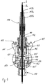
- the hose package 2 runs approximately from the rear end 6 of the arc welding torch device 1 to the welding torch at the front end 5 on the welding process side Fig. 2 is shown, a plurality of replaceable wear parts are arranged in the interior of the arc welding torch 1, which will be discussed in more detail below.
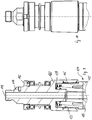
- Fig. 2 the rear end 6 of the arc welding torch device 1 facing away from the welding process point and the associated front open end 5 of the arc welding torch device 1 together with two drive rollers 10, 11 of a wire feed device 12 is shown in a detail view.
- the welding wire 7 is shown between the two drive rollers 10, 11 opposite one another with their peripheral surfaces.
- the drive rollers 10, 11 are located directly opposite the rear end 6 of the arc welding torch device 1 facing away from the process point of the arc welding torch 1 through hole 16 open towards the outer end of the end cap 14 ( Fig. 3 ) having.
- the end cap 14 is open towards the process-side end of the arc welding torch device and from there is provided with a stepped central recess 17 in the direction of the open through-hole 16.
- the latter initially has a constant larger diameter 18, which merges into a smaller diameter 19 of the recess, which is constant in comparison therewith.
- the latter area in turn merges into the through hole 16.
- the inner peripheral surface of the smaller diameter portion 19 is provided with an internal thread 19a.
- the inner circumferential surface of the region of the larger diameter 18 also has an internal thread 18a. The latter extends until shortly before the transition to the smaller diameter 19.
- the outer or jacket surface of the end cap 14 has a section 14a which widens conically from the end in the direction of the process point and which merges into a section 14b of the jacket surface with a constant diameter. With its end face 20 facing the process point, the end cap 14 abuts an outer shoulder 21 of the jacket tube 2 of the arc welding torch 1. The jacket tube 2 protrudes into the area of the larger inner diameter 18 of the end cap 14 until shortly before the transition to the smaller diameter 19.
- An inner diameter 23 of a through recess of the jacket tube 2 in the area of its front end corresponds to the smaller diameter 19 of the recess 17 of the end cap 14, so that a sleeve-shaped inlet body 25 with its outer jacket surface can be received in the jacket tube 2 at least substantially in a form-fitting manner.
- the through recess 24 of the jacket tube 2 has a shoulder 26 with a smaller inner diameter, the shoulder being provided as a stop for the inlet body 25.
- a recess 28 or a radially circumferential groove is formed on the outer surface or on the outer jacket surface of the sleeve-shaped inlet body 25, which is intended to receive a sealing element 29 or sealant, such as an O-ring in particular.
- a section of the outer surface of the inlet body 25, which is located opposite the smaller diameter 19 of the recess of the end cap 14, is provided with an external thread 30, which in the internal thread 19a of the cylindrical peripheral surface of the section with the smaller diameter 19 of the recess 17 of the end cap 14 can be screwed in.
- the sleeve-shaped inlet body 25 is formed with a through recess 25a which is provided with a consistently constant inner diameter. Only in the area in which a guide element 32, preferably without connection to the inlet body, is located in the through recess 25a of the inlet body 25, does the recess 25a have a recess 25b or groove for the arrangement of a sealing element 33 or sealant, such as an O-ring in particular.
- the sealing element arranged in the groove 25b of the inlet body 25 thus has contact with the outer circumferential surface of the guide body 32.
- the inlet body 25 has an outer jacket surface with different sections which differ from one another primarily in the size of the outer diameter.
- a first section of the outer jacket surface close to the rear end of the arc welding torch has the external thread 30, with which the inlet body 25 is screwed into the internal thread 19a of the end cap 14 and thereby releasably connected to the end cap 14.
- the external thread 30 is followed by a recess 35, which in turn is followed by a threadless section 36 of the outer circumferential surface, which has the same external diameter as the threaded section 30.
- the threadless section 36 has the circumferential groove 28 into which the further sealing element 29 can be received, in the case of the illustrated embodiment, an O-ring.
- a further, last, section 37 of the outer jacket surface of the inlet body 25 then follows, which likewise has a constant but smaller outer diameter than the preceding section.
- the shoulder 38 formed by means of the change in diameter, between the last section 37 of the outer jacket surface and the section 36 preceding it, results in an insertion or rotation limitation for the jacket tube 2 on the inlet body.
- the jacket tube 2 in turn has in the region of its front end on its outer jacket surface an external thread 39, onto which the end cap 14 is screwed with its internal thread 18a.
- the screwing-in movement is limited by the end face 20 of the end cap 14 pushing against the shoulder 21 of the jacket tube. Reaching this position can be a visual check that the end cap is correctly mounted and screwed.
- Fig. 3 the wire feed side or rear end 6 of the arc welding torch device 1 is shown in an exploded view and situation, as it also occurs when the wire core 8a is changed.
- the inlet body 25 is screwed into the end cap 14 during operation of the arc welding torch device 1.
- all seals are inserted in their grooves and remain there even when the wire core is changed.
- the jacket tube 2 is not shown, which is connected unchanged to the end cap 14 by its common screw connection and remains connected even during the change of the wire core 8a.
- the first Arc welding torch is dismantled at the process-side end 5 to such an extent that the wire core 8a and the guide element 32 can be pulled out together from the process-side end 5.
- a current arc welding torch from the applicant in which the invention described here is to be integrated in the future, for example the gas nozzle, a current contact nozzle and possibly a nozzle assembly can be detached from the arc welding torch and removed from the welding wire.
- the wire core 8a can then be pulled out of the arc welding torch from the process-side end 5.
- the guide body 32 seated on the wire core 8a and connected to the latter by a press fit, together with the wire core is pulled out of the arc welding torch device 1.
- the guide element seated in the recess of the end cap and the recess of the inlet body in this exemplary embodiment largely without connection to the two components can thus be pulled out of the two components as well as from the arc welding torch 1 together with the wire core 8a without additional effort, in particular without great effort .
- all that has to be overcome is a comparatively low holding force acting on the outer surface of the guide element through an O-ring seal.
- a new wire core 8a can then be arranged with one of its two ends on the welding wire 7 and inserted into the guide body 32 and arranged.
- the guide body 32 can then be pushed together with the wire core 8a together and in a single operation on the welding wire 7 into the welding torch and thus also into the arc welding torch device 1.
- This insertion movement in the direction of the end cap 14 is continued until the guide body 32 with its end 32a on the end cap and serving as a position indicator is completely guided through the open through recess 16 of the end cap 14 and the end 32a of the guide element 32 outwards out of the end cap 14 protrudes.
- the optically recognizable end of the guide element 32 which is arranged outside the arc welding torch device 1 with one of its ends 32a, is a Possibility of checking is given in order to be able to recognize without additional technical effort whether the guide body 32 and the wire core 8a are arranged within the arc welding torch device 1 in their predetermined target positions.
- the end 32a of the component of the guide body 32 that is visible outside the end cap 14 also represents a check as to whether the newly introduced wire core 8a and 8a the guide bodies 32 of which are arranged in such a way that the arc welding torch 1 is sealed against escape of protective gas from the end 6 of the arc welding torch 1 on the end cap.
- the component of the guide body 32 has the cylindrical end region section 32a facing the wire feed device in its position of use on the arc welding torch 1, which in the exemplary embodiment is elongated and has a constant outer diameter.
- the end region section 32a merges into a section 32b which enlarges conically towards the end 5 on the process side and which in turn is adjoined by a cylindrical section 32c with a larger, preferably constant, outer diameter.
- section 32c has a shoulder to a slightly reduced outer diameter.
- a front outer diameter of section 32c in the insertion direction corresponds approximately to the inner diameter of through recess 25a of inlet body 25, the guide body is guided within the inlet body during its advancing movement.
- the end region section 32a is also aligned in the correct position and in this case arranged concentrically around the longitudinal axis 3 and can be inserted into the through recess 16 of the end cap 14. Since the end region portion 32a has a constant outer diameter which is only slightly smaller than the diameter of the through recess 16, the end region portion 32a can be completely inserted into the through recess and part of the end region portion 32a out of the through recess 16 of FIG End cap to be led out to the outside.
- position indicator means This part of the end region section, which can be referred to as position indicator means, is thus recognizable from the outside in its end position in the welding torch 1 and is located comparatively close to the point of application of the wire feed device at which the feed movement is applied to the welding wire 7.
- This position display means can be used for the externally visually perceivable signaling of a correctly positioned arrangement of the guide body and the wire core 8a in the interior of the arc welding torch.
- the one-piece component of the guide body 32 is provided with a through recess 34 which, in the area of the end region section 32a, has a preferably constant diameter which is only slightly larger than the diameter of the welding wire used in this case.
- the through recess 34 In the area of the section 32c with the larger outer diameter, the through recess 34 has a larger, but also constant diameter, as a result of which the rear end of the wire core 8a can be arranged in this area of the through bore.
- the inside diameter of the recess 34 in this area corresponds approximately to the outside diameter of the wire core. With its front end, the wire core 8a abuts the shoulder 34a resulting from the change in diameter in the through recess 34.
- the one-piece nature of the guide body 32 results in good guiding properties for the welding wire in the guide body 32, with at most a low risk of the welding wire 7 getting caught during its movement and thereby buckling.
- Such a system can in particular have identical guide bodies in their geometrical outer shape, but which differ in terms of the diameter of the respective through recess 34 and possibly also in terms of the materials used for the guide elements, whereby an adaptation to the respective material of the welding wire can take place in an advantageous manner.
- the section of the component of the guide element with the smaller outer diameter, which is guided through the end cap 14 and protrudes from it, can be referred to as an anti-kink means.
- the invention also has the advantage that, unlike in the past, the end cap 14 neither guides nor touches the welding wire 7 nor the wire core 8a and thus the end cap 14, which is usually elaborately designed, is no longer a wear part.
- FIG. 4 and 5 another preferred embodiment of the invention is shown. This is largely identical to the preferred embodiment from FIG Figs. 1 to 3 why to avoid of repetitions, only the differences are discussed below. The above description of the Figs. 1 to 3 is therefore also for the embodiment of Fig. 4 and 5 incorporated by reference.
- the main difference to the embodiment of an arc welding torch device according to the Fig. 1-3 consists in the fact that the guide element 32 has (only) a section 32c with a larger diameter, which has a constant diameter throughout, after its conical section 32b, viewed in the direction of the process-side end of the burner.
- the guide element 32 has (only) a section 32c with a larger diameter, which has a constant diameter throughout, after its conical section 32b, viewed in the direction of the process-side end of the burner.
- there is no increase in diameter on the outer surface of the guide element following the conical section - and viewed in the direction of the process-side end - which could be used for a form-fitting and / or force-fitting holding of the guide element.
- there is no sealing element such as the sealing element 33 from the other embodiment of FIG Fig. 2 and 3 , on the outer periphery of the constant diameter portion 32c.
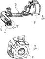
- FIG. 6-13 shows, inter alia, an articulated arm robot 101, as it is already used in many ways.
- the articulated arm robot 101 is designed as a so-called hollow shaft robot, which is used in connection with the Invention particularly suitable.
- suitable robots can be, for example, the robots of the AR or MA series, which are offered by the company Yaskawa Europe GmbH, 65760 Eschborn.
- the robot has a frame part 102 and an arm 103 which is arranged thereon and which is provided with a plurality of joints 104.
- the free end 105 of the arm of the articulated arm robot 101 is thereby able to follow any three-dimensional movement paths.
- connection flange 106 of a connection device which is used to hold a welding torch 107 ( Fig. 6 ) the arc welding torch device is provided.
- the connecting flange 106 can execute a motor-driven rotational movement about an axis of rotation 108 and relative to the last link of the arm 103.
- a spacer block is drawn in front of the burner, which serves as an extension of the connection flange 106 of the robot and can be provided as an option and not necessarily.
- the arc welding torch 107 shown in more detail has a fastening device 109 and a receiving device 110 ( Fig. 7 ).
- the fastening device 109 is provided to connect the welding torch 107 to the connecting flange 106 of the robot arm 103 in a detachable, but non-rotatable manner.
- the receiving device 110 serves to receive a welding torch neck 111 of the welding torch 107 and to transfer the welding current to the welding torch neck 111, which will be explained in more detail below executing connecting flange 106 of the robot is connectable, the receiving device 110 and the fastening device 109 are also referred to collectively as part of a rotor which can perform such rotational movements by means of driven movements of the connecting flange about the axis of rotation 108.
- the rotor is non-rotatably connected to the connecting flange, in particular detachably connected.
- the rotor In relation to the last link of the robot arm 103 to which the connecting flange 106 is attached, the rotor can be rotated about the axis 108.
- the robot shown in the figures has a total of six driven axes, this number being only an example of the possible uses of the arc welding torch. In connection with the arc welding torch according to the invention, articulated arm robots with a different number of driven movement axes can also be used.
- a stationary stator located on the inside opposite the rotor and the last link of the robot arm 103 has a tubular passage 114 which is arranged centrally in the welding torch device and has a cylindrical recess 115.
- a longitudinal axis 116 of the recess 115 is aligned with the axis of rotation 108 of the connecting flange 106.
- the bushing 114 extends approximately over the entire length of the fastening device and the receiving device.
- the upper end of the bushing 114 on the robot side is provided with an external thread 117 serving as an electrical connection to which a coaxial cable 118 ( Fig. 6 and Fig. 7 ) can be detachably fastened by screwing on.
- a cone 119 ( Fig. 8 ) can be provided as a conductive contact between a welding current cable 118a of the coaxial cable 118 and the bushing 114.
- the welding current cable 118a which is provided with external insulation 118b, is arranged coaxially around a central channel 118c.
- the central channel 118c can serve to feed the welding wire 7 to the welding torch by means of a feed movement and to allow a protective gas to flow to the front end of the welding torch 107.
- the bushing 114 is surrounded by a bell-shaped section 123 with a circular cross-section ( Fig. 8 and Fig. 9 ) of the stator, which is connected to the bushing in an electrically conductive manner.
- the bell-shaped section 123 and the passage 114 are connected in one piece.
- a contact device is located on the feedthrough 114 essentially within the bell-shaped section 123 124 arranged, which has a slip ring 125 arranged in the bell-shaped section.
- the contact device 124 has a grinding surface 126 formed on the end face on the slip ring 125.
- the grinding surface 126 is force-loaded by a compression spring 127 acting parallel to the longitudinal axis 116 of the feedthrough 114.
- the compression spring 127 is supported on the inside on the bell-shaped section 123 of the stator and presses the grinding surface 126 against a likewise essentially annular surface of a connecting bell 135.
- Both the annular surface of the connecting bell 135 and the grinding surface 126 are part of a contact device 124 and are each concentric arranged around the longitudinal axes 108, 116 and penetrated by a continuation of the recess 115.
- the contact lamellas 145 Between the slip ring 125 and an inside of the bell-shaped section 123 there are contact lamellas 145, which establish the electrical contact between the slip ring 125 and the bell-shaped section 123.
- the spring action of the contact lamellas 145 has the effect that electrical contact is established between the slip ring 125 and an inner surface 133 of the bell-shaped section 123.
- the material of the slip ring 125 is a good electrical conductor, for example copper or a copper alloy.
- the contact lamellas 145 can preferably be silver-plated accordingly in order to ensure a particularly good electrical current transfer.
- the side of the slip ring 125 facing away from the compression spring 127 with its slip surface 126 ( Fig. 9 ) is designed as a stationary component and as part of the stator and acts as an electrical transition to the rotor which is rotatable about the longitudinal axis 108 and to which the connecting bell 135 belongs.
- the connecting bell 135 connects to the slip ring 125 in the direction of the longitudinal axis 116 of the feedthrough 114 and in the direction of the end on the welding torch side ( Fig. 8 ), which is also electrically conductive due to a preferably silver-plated surface.
- the feedthrough 114, the slip ring 125 and the connecting bell 135 have aligned central bores, which overall are part of a central recess 115 running along the longitudinal axis 108.
- the compression spring 127 thus presses on the slip ring 125, which in turn presses on the connecting bell 135 via its grinding surface 126, and the latter is therefore constantly in contact with the grinding surface 126, in particular in electrically conductive contact.
- the connection bell 135 is additionally secured with respect to its axial position on the bushing by means of a ring 148. Furthermore, the connecting bell 135 is paired with the conical outer surface of the “brass flange with socket” 149 via a conical, silver-plated inner surface and is axially centered.
- a seal 136 is located between the bell-shaped element 123 of the stator and the slip ring 125 in a groove 150 of the slip ring 125, with which it can be ensured that the bell-shaped element 123 sits gas-tight on the slip ring 125 as part of the stator.
- a "brass flange with socket" 149 which is paired with the preferably silver-plated connecting bell 135 via a cone, is screwed via a plastic insulating sleeve 151 to a fastening element 152, which is part of the fastening device and serves as a counterpart for the welding torch connection.
- the housing 141, an end cover 142 adjoining one end of the housing 141 and a cover 154 adjoining the other end of the housing 141 in the direction of the welding torch neck 111 are designed as plastic components in the exemplary embodiment.
- the housing 141 also contains the fastening device 109 for fastening to the connecting flange 106 on a hollow-shaft robot and, together with the cover 154 and the end cover 142, electrically encloses and insulates the internal structure.
- the receiving device 110 of the welding torch is made of metallic, electrically conductive material, but it is also separated from current-carrying components via the plastic sleeve 151 with a flange as an insulator. The receiving device 110 for the welding torch is accordingly passed through the plastic housing 141 and the cover 154.
- the fastening device 109 embodied as part of the plastic housing 141 is non-rotatably but detachably connected to the connection flange of the robot 106.
- the receiving device 110 for the welding torch, to the fastening element 152 of which a welding torch is releasably connected in a rotationally fixed manner, is also connected non-rotatably to the plastic housing 141.
- the housing 141 which is on the outside of the welding torch, is a component of the rotor of the arc welding torch.
- This rotor is arranged concentrically to the internal stator of the arc welding torch and with respect to the axis of rotation 108 and can rotate about the latter due to motor-driven rotational movements of the connecting flange 106 of the robot relative to the internal stator.
- the stator on the other hand, is stationary when the rotor moves together with the robot-side connecting flange 106 and does not rotate with it.
- this fixed arrangement with respect to the connecting flange 106, the fastening device 109 and the rotor can be achieved overall, for example, in that the welding cable is fastened to the thread 117 of the bushing 114 and is fixed in its rotative position due to the torsional rigidity of the welding cable.
- an additional anti-rotation device for the stator on the robot can also be provided.
- the stator has at least the components, the bushing 114 and the slip ring 125 together with the compression spring 127.
- the rotor is mounted on the stator by means of bearings 143, here in the exemplary embodiment ball bearings.
- the plastic housing 141 is closed with the cover 154, which covers the fastening ring 153, towards the welding torch.
- the housing 141 is covered by the cover 142 towards the welding torch cable. If it appears necessary, the stator can also be fixed to a rotationally fixed component of the robot, for example via the cover 142.
- the electrical current required to carry out a welding process flows, beginning with the welding current cable 118a, which is connected to the stator bushing 114 via the screw connection on the external thread 117, in the stator to the bell-shaped section 123. There are the contact lamellas 145, over which the Current is transmitted to the slip ring 125, which also belongs to the stator. The current is transmitted to the silver-plated connecting bell 135 via the sliding contact between the sliding surface 126 and the connecting bell 135.
- the connecting bell 135 is part of the rotor and rotates with a driven rotational movement of the connecting flange 106 together with the housing 141 about the axis of rotation 108 Socket is paired and thus has a tightly pressed fit and thus has good power transmission properties.
- the brass bushing 149 there is another electrically conductive contact lamella 155 X6, with which the welding current is transmitted to the welding torch via an inserted inner tube.
- the burner is fastened via the fastening element 152, which is insulated from the inner tube.
- the protective gas can flow via the coaxial cable 118 through the recess 115 of the feedthrough 114 to the welding torch neck 111.
- the welding wire 7 can also be fed to the welding torch neck 111 in the same way and pushed in each time. If necessary, a data cable (not shown) can be integrated into the coaxial cable 118.
Abstract
Um bei einer Lichtbogenschweißbrennereinrichtung mit einer als Schweißdraht ausgebildeten abschmelzenden Elektrode, wobei die Elektrode mit einer Bewegungsrichtung von einem hinteren Ende der Lichtbogenschweißbrennereinrichtung zum Vorschub in Richtung eines vorderen Endes der Lichtbogenschweißbrennereinrichtung vorgesehen ist, in dessen Bereich die Elektrode während eines Lichtbogenschweißprozesses abschmilzt, die Elektrode in der Lichtbogenschweißbrennereinrichtung in einer austauschbaren Drahtseele geführt ist, wobei die Drahtseele wiederum zumindest im Bereich des hinteren Endes des Lichtbogenschweißbrenners in einem die Drahtseele umgebenden und als austauschbares Verschleißteil ausgebildetes Führungselement angeordnet ist, wobei das Führungselement der Drahtseele zum gemeinsamen verschleißbedingten Austausch der Drahtseele vorgesehen ist, im Bereich des prozeßseitigen Endes eine möglichst widerstandslose Bewegung des Schweißdrahts mit einer möglichst geringen Gefahr, daß der Schweißdraht aufgrund der Vorschubbewegung ausknickt, zu erreichen, wird eine einstückige Ausbildung des Führungselements zusammen mit einem Bauteil der Lichtbogenschweißbrennereinrichtung vorgeschlagen, das für den Eintritt des Schweißdrahts in die Lichtbogenschweißbrennereinrichtung eine Eintrittsöffnung aufweist, sowie für die Führung eines als Elektrode vorgesehenen abschmelzenden Schweißdrahts von der Eintrittsöffnung bis zumindest dem hinteren Ende der Drahtseele vorgesehen ist.In the case of an arc welding torch device with a consumable electrode designed as a welding wire, the electrode is provided with a direction of movement from a rear end of the arc welding torch device to advance in the direction of a front end of the arc welding torch device, in the area of which the electrode melts during an arc welding process, the electrode in the Arc welding torch device is guided in an exchangeable wire core, the wire core in turn being arranged at least in the area of the rear end of the arc welding torch in a guide element surrounding the wire core and designed as an exchangeable wear part, the guide element of the wire core being provided for joint wear-related replacement of the wire core, in the area of the process-side end a movement of the welding wire with as little resistance as possible with the least possible risk that the Schw In order to achieve a one-piece construction of the guide element together with a component of the arc welding torch device, which has an inlet opening for the entry of the welding wire into the arc welding torch device, and for guiding a consumable welding wire provided as an electrode from the inlet opening to at least the rear end of the wire core is provided.
Description
Die Erfindung betrifft eine Lichtbogenschweißbrennereinrichtung mit einer abschmelzenden Elektrode, wobei die Elektrode mit einer Bewegungsrichtung von einem hinteren Ende der Lichtbogenschweißbrennereinrichtung zum Vorschub in Richtung eines vorderen Endes der Lichtbogenschweißbrennereinrichtung vorgesehen ist, in dessen Bereich die Elektrode während eines Lichtbogenschweißprozesses abschmilzt, die Elektrode in der Lichtbogenschweißbrennereinrichtung in einer austauschbaren Drahtseele geführt ist, wobei die Drahtseele wiederum zumindest im Bereich des hinteren Endes der Lichtbogenschweißbrennereinrichtung in einem die Drahtseele umgebenden und als austauschbares Verschleißteil ausgebildetes Führungselement angeordnet ist, wobei das Führungselement der Drahtseele zum gemeinsamen verschleißbedingten Austausch der Drahtseele vorgesehen ist.The invention relates to an arc welding torch device with a consumable electrode, the electrode being provided with a direction of movement from a rear end of the arc welding torch device to advance in the direction of a front end of the arc welding torch device, in the area of which the electrode melts during an arc welding process, the electrode in the arc welding torch device in an exchangeable wire core, the wire core in turn being arranged at least in the area of the rear end of the arc welding torch device in a guide element surrounding the wire core and designed as a replaceable wear part, the guide element of the wire core being provided for joint wear-related replacement of the wire core.
Es existiert eine Vielzahl von unterschiedlichen Schweißverfahren. Die vorliegende Erfindung hat besondere Bedeutung für das Lichtbogenschweißen. Dieses basiert auf einer Hitzeentwicklung eines elektrischen Lichtbogens zwischen einer Schweißelektrode und einem Werkstück, an dem eine Schweißung vorgenommen werden soll. Durch die Hitzeentwicklung kann der bzw. können die zu schweißenden Werkstoffe lokal aufgeschmolzen werden. Bei nahezu sämtlichen Lichtbogenschweißverfahren wird dem Bereich des Lichtbogens hierzu ein Schutzgas zugeführt, um einerseits eine widerstandssenkende ionisierte Atmosphäre zwischen der Schweißelektrode und dem Werkstück zu ermöglichen und um andererseits eine Oxidation der Schweißelektrode und des Werkstücks zu verhindern. Anstelle eines hierbei als Schutzgas vorgesehenen Inertgases kann auch ein Aktivgas oder eine Mischform zugeführt werden, das zur Reaktion dient. Ebenso können Elektroden vorgesehen sein, die keine externe Gaszuführung benötigen, da die hierfür erforderlichen Substanzen in den Elektroden integriert sind und beim Abschmelzen der Elektroden freigesetzt werden.There are a number of different welding processes. The present invention has particular relevance to arc welding. This is based on the heat generated by an electric arc between a welding electrode and a workpiece on which welding is to be carried out. Due to the heat development, the material or materials to be welded can be melted locally. In almost all arc welding processes, a protective gas is supplied to the area of the arc, on the one hand to enable a resistance-reducing ionized atmosphere between the welding electrode and the workpiece and, on the other hand, to prevent oxidation of the welding electrode and the workpiece. Instead of an inert gas provided here as a protective gas, an active gas or a mixed form can also be supplied, which is used for the reaction. Likewise, electrodes can be provided that do not require an external gas supply, since the substances required for this are integrated in the electrodes and are released when the electrodes melt.
Ein Lichtbogen-Schweißbrenner ist üblicherweise derart ausgelegt, daß ein Benutzer oder ein Roboter einen Metallschweißdraht, der auch als Metallzusatzwerkstoff bezeichnet werden kann, auf eine spezifizierte Fügestelle auf dem Zielmetallstück richten kann. Der Schweißdraht wird durch den Schweißbrenner geführt und schließlich durch eine Öffnung in der Kontaktdüse am prozeßseitigen Ende des Schweißbrenners zum Zielmetallstück transportiert.An arc welding torch is usually designed in such a way that a user or a robot can point a metal welding wire, which can also be referred to as a metal filler material, at a specified joint on the target metal piece. The welding wire is passed through the welding torch and finally transported to the target metal piece through an opening in the contact nozzle at the process-side end of the welding torch.
Bei Anlegen einer elektrischen Spannung am Schweißbrennerinnenrohr und beim Kontaktieren des Schweißdrahtes mit dem Zielmetallstück, fließt ein hoher elektrischer Strom von einem Schweißbrennerinnenrohr über einen sogenannten Düsenstock, dann über die Kontaktdüse, über den Schweißdraht und gegebenenfalls einem Lichtbogen zum Zielmetallstück und dann zur Masse. Der hohe Strom und der Lichtbogen verursachen das Schmelzen des Schweißdrahtes in einer Schutzgasatmosphäre, was zur Tropfenbildung des Drahtes und zum Entstehen eines Lichtbogens führt.When an electrical voltage is applied to the welding torch inner tube and when the welding wire comes into contact with the target metal piece, a high electrical current flows from a welding torch inner tube via a so-called nozzle holder, then over the contact nozzle, over the welding wire and, if necessary, an arc to the target metal piece and then to the ground. The high current and the arc cause the welding wire to melt in a protective gas atmosphere, which leads to the formation of droplets in the wire and the creation of an arc.
Dieser Lichtbogen schmilzt das Metall der Zielmetallstücke und den nachgeführten Schweißdraht. Durch Abfallen der entstanden Tropfen des Schweißdrahtes oder durch Übergabe des Tropfens im Kurzschluss auf die verflüssigte Stelle der Zielmetallstücke, werden diese miteinander verbunden. Aufgrund des geringen Abstandes von der Kontaktdüse und der Gasdüse zum Lichtbogen bzw. zum aufgeheizten Zielmetallstück werden diese Bauteile stark erwärmt. Durch die hohe thermische Belastung ist vor allem die Kontaktdüse starkem Verschleiß ausgesetzt.This arc melts the metal of the target metal pieces and the following welding wire. When the drops of the welding wire fall off or when the drops are transferred in a short circuit to the liquefied point of the target metal pieces, they are connected to one another. Due to the small distance from the contact nozzle and the gas nozzle to the arc or the heated target metal piece, these components are very heated. Due to the high thermal load, the contact nozzle in particular is exposed to heavy wear.
Herkömmliche Brennersysteme bestehen in ihrem vorderen, schweißprozeßseitigem, Endabschnitt in der Regel im Wesentlichen aus der Kontaktdüse, dem Düsenstock und der äußeren Gasdüse. Diese Bauteile sind am Brennerhals (Außenrohr, Innenrohr) in der Regel lösbar montiert und thermisch bzw. elektrisch über Kontaktflächen, Gewinde miteinander oder mit anderen Bauteilen des Brennerhalses gekoppelt oder auch isoliert. Das Außenrohr muss jedoch von stromführenden anderen Bauteilen elektrisch entkoppelt sein, da dort aus Sicherheitsgründen keine Spannung anliegen darf. Durch die thermische Kopplung der Bauteile wird versucht, die Energie, welche in Form von Wärme in die Kontaktdüse bzw. Gasdüse eingeleitet wird, über das Außenrohr bzw. Innenrohr möglichst wirksam abzuleiten und dadurch die Maximaltemperatur der Kontaktdüse zu senken, um den Verschleiß zu minimieren.Conventional torch systems consist in their front end section on the welding process side, as a rule, essentially of the contact nozzle, the nozzle holder and the outer gas nozzle. These components are usually detachably mounted on the torch neck (outer tube, inner tube) and thermally or electrically coupled to one another or to other components of the torch neck or also insulated via contact surfaces, threads. However, the outer tube must be electrically decoupled from other live components, since there are none for safety reasons Voltage may be present. The thermal coupling of the components attempts to dissipate the energy, which is introduced into the contact nozzle or gas nozzle in the form of heat, via the outer tube or inner tube as effectively as possible and thereby lower the maximum temperature of the contact nozzle in order to minimize wear.
Üblicherweise wird bei gattungsgemäßen Lichtbogenschweißbrennereinrichtungen im Bereich von deren hinterem Ende der als abschmelzende Elektrode fungierende Schweißdraht des Lichtbogenschweißbrenner sowie das Schutzgas zugeführt, sofern das jeweilige Schweißverfahren ein solches Gas vorsieht. Der Schweißdraht wird durch das Innere des Lichtbogenschweißbrenners von dessen hinterem Ende bis zum Austritt aus dem vorderen, prozeßseitigem Ende entsprechend des Verbrauchs vorgeschoben. Hierzu ist im Bereich des hinteren Endes ein an sich vorbekannter Drahtvorschub angeordnet, der beispielsweise mittels eines angetriebenen Räderpaares den Schweißdraht vorschiebt und durch das Innere der Lichtbogenschweißbrennereinrichtung bewegt. Um das Innere der Lichtbogenschweißbrennereinrichtung selbst vor Verschleiß aufgrund der Vorschubbewegung des Schweißdrahts zu schützen, wird der Schweißdraht üblicherweise in einer sogenannten Drahtseele angeordnet. Der Verschleiß aufgrund der Vorschubbewegung des Schweißdrahts findet somit vor allem in der Drahtseele und nicht an Bauteilen des Gehäuses der Lichtbogenschweißbrennereinrichtung statt. Letztere verschleißt somit anstelle des Inneren der Lichtbogenschweißbrennereinrichtung selbst. Als Folge davon ist es erforderlich, dass die Drahtseele von Zeit zu Zeit verschleißbedingt ausgetauscht wird.In the case of arc welding torch devices of the generic type, the welding wire of the arc welding torch, which functions as a consumable electrode, and the shielding gas are supplied in the region of their rear end, provided the respective welding process provides for such a gas. The welding wire is advanced through the interior of the arc welding torch from its rear end to the exit from the front, process-side end according to the consumption. For this purpose, a previously known wire feed is arranged in the region of the rear end, which feeds the welding wire for example by means of a driven pair of wheels and moves it through the interior of the arc welding torch device. In order to protect the interior of the arc welding torch device itself from wear due to the feed movement of the welding wire, the welding wire is usually arranged in a so-called wire core. The wear due to the feed movement of the welding wire thus takes place primarily in the wire core and not on components of the housing of the arc welding torch device. The latter thus wears instead of the interior of the arc welding torch device itself. As a result, it is necessary for the wire core to be replaced from time to time due to wear.
Herkömmlicherweise ist es für den verschleißbedingten Austausch der Drahtseele erforderlich, dass der Schweißbrennereinrichtung demontiert wird, insbesondere auch und vor allem das dem schweißprozessseitigen Ende abgewandte hintere andere Ende der Lichtbogenschweißbrennereinrichtung, das sich gegenüber den Drahtvorschubmitteln befindet. Dies ist mit großem zeitlichen Aufwand für die Demontage und Montage der Lichtbogenschweißbrennereinrichtung verbunden. Aus der
Unabhängig davon, ob die Drahtseele vom vorderen oder vom hinteren Ende der Lichtbogenschweißbrennereinrichtung aus gewechselt wird, stellt sich bei beiden Lösungen das Problem, dass im Betrieb der Lichtbogenschweißbrennereinrichtung der Schweißdraht zwischen den üblicherweise als rotierendes Rollenpaar ausgebildeten Drahtvorschubmitteln und dem hinteren, den Drahtvorschubmitteln unmittelbar gegenüberliegenden Ende, dazu tendieren kann zu knicken. Der durch die Drahtvorschubmittel geschobene Schweißdraht läuft durch eine enge Bohrung einer Endkappe in die Lichtbogenschweißbrennereinrichtung ein. Tritt hierbei ein Widerstand auf, beispielsweise aufgrund von Reibung des Schweißdrahts in der Bohrung, kann hierdurch der Draht außerhalb der Endkappe auslenken und knicken. Um dem entgegen zu wirken, wird üblicherweise die Stirnseite der Endkappe konisch gestaltet, damit die Endkappe ein Stück weit in den trichterförmigen Bereich zwischen den beiden Antriebsrollen eingeschoben werden kann. Der dadurch etwas verkürzte Bereich zwischen der Kontaktstelle der Antriebsrollen mit dem Schweißdraht und der Einlaufstelle des Schweißdrahts der Endkappe, in dem sich der Schweißdraht sich noch nicht im Lichtbogenschweißbrenner bzw in der ihn schützenden Drahtseele befindet, verringert zwar etwas das Problem des Knickens, allerdings nur geringfügig. Die Gefahr eines Ausknickens ist trotzdem weiterhin praxisrelevant vorhanden, insbesondere aber nicht nur bei sehr dünnen, weichen Drähten.Regardless of whether the wire core is changed from the front or the rear end of the arc welding torch device, the problem arises with both solutions that when the arc welding torch device is in operation, the welding wire is between the wire feed means, which are usually designed as a rotating pair of rollers, and the rear end directly opposite the wire feed means , can tend to buckle. The welding wire pushed through the wire feed means runs into the arc welding torch device through a narrow bore in an end cap. If resistance occurs here, for example due to friction of the welding wire in the bore, this can cause the wire to deflect and kink outside the end cap. To counteract this, the end face of the end cap is usually designed to be conical so that the end cap can be pushed a little way into the funnel-shaped area between the two drive rollers. The slightly shortened area between the contact point of the drive rollers with the welding wire and the entry point of the welding wire of the end cap, in which the welding wire is not yet in the arc welding torch or in the wire core protecting it, reduces the problem of kinking somewhat, but only slightly . Nevertheless, the risk of kinking is still relevant in practice, but especially not only in the case of very thin, soft wires.
Der Erfindung liegt deshalb die Aufgabe zugrunde, eine Maßnahme vorzuschlagen, durch welche sich im Bereich des prozeßseitigen Endes eine möglichst widerstandslose Bewegung des Schweißdrahts mit einer möglichst geringen Gefahr, daß der Schweißdraht aufgrund der Vorschubbewegung ausknickt, erreichen läßt.The invention is therefore based on the object of proposing a measure by means of which as far as possible in the area of the process-side end Resistance-free movement of the welding wire with the lowest possible risk that the welding wire kinks due to the feed movement can be achieved.
Diese Aufgabe wird bei einer Lichtbogenschweißbrennereinrichtung der eingangs genannten Art erfindungsgemäß durch eine einstückige Ausbildung eines Bauteils der Lichtbogenschweißbrennereinrichtung gelöst, das für den Eintritt des Schweißdrahts in den Lichtbogenschweißbrenner eine Eintrittsöffnung einer Durchgangsausnehmung aufweist, sowie für die Führung des Schweißdrahts im Lichtbogenschweißbrenners innerhalb der Durchgangsausnehmung von der Eintrittsöffnung bis zumindest dem hinteren Ende der Drahtseele vorgesehen ist, wobei dieses eine Bauteil auch als ein aus der Lichtbogenschweißbrennereinrichtung herausragendes und zwischen einer äußeren Endkappe des Gehäuses der Lichtbogenschweißbrennereinrichtung und dem Drahtvorschubmittel angeordnetes Knickschutzmittel für den Schweißdraht vorgesehen ist, in welchem der Schweißdraht in der Durchgangsausnehmung geführt ist.This object is achieved in an arc welding torch device of the type mentioned in accordance with the invention by a one-piece construction of a component of the arc welding torch device which has an inlet opening of a through recess for the entry of the welding wire into the arc welding torch, as well as for guiding the welding wire in the arc welding torch within the through opening of the entrance opening until at least the rear end of the wire core is provided, this one component also being provided as an anti-kink means for the welding wire which protrudes from the arc welding torch device and is arranged between an outer end cap of the housing of the arc welding torch device and the wire feed means, in which the welding wire is guided in the through recess .
Der Erfindung liegt somit der Gedanke zugrunde, den Schweißdraht von seinem Eintritt in die Lichtbogenschweißbrennereinrichtung bis zum hinteren Ende der Drahtseele in lediglich einem einzigen Bauteil zu führen und ihn in diesem Bauteil an die Drahtseele zu übergeben. Dieses weitere Bauteil soll sich vorzugsweise zumindest von der Endkappe aus in Richtung zum Drahtvorschubmittel erstrecken. Vorzugsweise ist die schweißprozeßseitige Stirnseite dieses einstückigen Bauteils jedoch im Bereich der Längsachse des Schweißdrahts mit Abstand zur Innenseite der Endkappe angeordnet, wobei dieser Abstand zur Ausbildung der Aufnahme für die Drahtseele in diesem Bauteil vorgesehen sein kann. Außerdem soll dieses als zusätzliches Bauteil zur Endkappe vorgesehene und vorzugsweise auch als Knickschutzmittel ausgebildete Bauteil im Bereich seines drahtvorschubseitigen Endes eine möglichst geringe radiale äußere Erstreckung in Bezug auf die Längsachse des Schweißdrahts aufweisen, insbesondere eine deutlich geringere äußere radiale Ausdehnung in einer Ebene, die senkrecht zu den Drehachsen der vorzugsweise beiden Rollen des Drahtvorschubmittels ausgerichtet ist. Das Knickschutzmittel kann hierdurch durch die Endkappe hindurchgeführt sein und möglichst nahe an der Kontakt- und Wirkstelle des üblicherweise als zwei gegenläufige Rollen ausgebildeten Drahtvorschubmittel mit dem Schweißdraht angeordnet werden, wodurch die Strecke, entlang welcher der Schweißdraht geschoben wird und dabei frei und ungeführt verläuft, möglichst kurz gehalten werden kann. Das in das Bauteil integrierte Knickschutzmittel kann insbesondere in axialer Richtung, hin zu den Drahtvorschubmitteln, über die Endkappe vorstehen. Hierdurch ergibt sich eine längere Strecke, in welcher der geschobene Schweißdraht geführt ist, was die Neigung des Schweißdrahts in seinem ungeführten Abschnitt durch die Vorschubbewegung auszuknicken, maßgeblich verringert. Auch der saubere Einlauf des Drahtes beim automatisierten Einfädeln wird dadurch erheblich verbessert.The invention is thus based on the idea of guiding the welding wire from its entry into the arc welding torch device to the rear end of the wire core in just a single component and transferring it to the wire core in this component. This further component should preferably extend at least from the end cap in the direction of the wire feed means. However, the end face of this one-piece component on the welding process side is preferably arranged in the region of the longitudinal axis of the welding wire at a distance from the inside of the end cap, this distance being able to be provided for forming the receptacle for the wire core in this component. In addition, this component, which is provided as an additional component to the end cap and is preferably also designed as an anti-kink means, should have the smallest possible radial external extension in the area of its end on the wire feed side in relation to the longitudinal axis of the welding wire, in particular a significantly smaller external radial extension in a plane perpendicular to is aligned with the axes of rotation of the preferably two rollers of the wire feed means. The anti-kink means can thereby be passed through the end cap and be arranged as close as possible to the contact and active point of the wire feed means, which is usually designed as two opposing rollers, with the welding wire, whereby the distance along which the welding wire is pushed and thereby runs freely and unguided can be kept as short as possible. The anti-kink means integrated into the component can in particular protrude beyond the end cap in the axial direction towards the wire feed means. This results in a longer distance in which the pushed welding wire is guided, which significantly reduces the tendency of the welding wire to buckle in its unguided section due to the feed movement. This also significantly improves the clean entry of the wire during automated threading.
Eine Verbesserung eines sauberen Einlaufs des Schweißdrahts in das Knickschutzmittel und eine Verbesserung der Funktionssicherheit beim Einfädeln des Schweißdrahts in das Knickschutzmittel kann auch durch eine Fase der Begrenzungswand der Durchgangsausnehmung für den Schweißdraht im einstückigen Bauteil im Bereich der Eintrittsöffnung der Durchgangsausnehmung erreicht werden. Auch durch eine solche Fase tendiert der Schweißdraht weniger zu einem Verhaken mit der Begrenzungswand der Durchgangsausnehmung, wodurch das Risiko eines Knicks des Schweißdrahts weiter reduziert werden kann.An improvement in the clean entry of the welding wire into the anti-kink means and an improvement in the functional reliability when threading the welding wire into the anti-kink means can also be achieved by a bevel on the boundary wall of the passage recess for the welding wire in the one-piece component in the area of the entry opening of the passage recess. With such a bevel, too, the welding wire has less of a tendency to get caught in the boundary wall of the passage recess, as a result of which the risk of the welding wire kinking can be further reduced.
Es kann im Zusammenhang mit der vorliegenden Erfindung besonders zweckmäßig sein, wenn das Knickschutzmittel austauschbar ist, wodurch auf einen durch die Bewegung des Schweißdrahts im Knickschutzmittel bedingten Verschleiß reagiert werden kann. Auch diese Austauschbarkeit ist in einer bevorzugten Ausführungsform der Erfindung durch die einstückige Ausbildung mit dem die Drahtseele aufnehmenden Bauteils erzielbar. Da dieses die Drahtseele im Inneren des Lichtbogenschweißbrenners aufnehmende Bauteil vorzugsweise zusammen mit der Drahtseele zu deren gemeinsamen Austausch aus dem Lichtbogenschweißbrenner zu dessen schweißprozeßseitigen Ende gezogen und aus diesem herausgeführt werden kann, kann dieses Bauteil, welches auch das Knickschutzmittel enthält, auf einfache Weise gegen ein neues unverschlissenes Knickschutzmittel ausgetauscht werden. Dieses neue Bauteil wird dann zusammen mit einer neuen Drahtseele und mit dem daran einstückig ausgebildeten ebenfalls neuen Knickschutzmittel voran, vom schweißprozeßseitigem Ende wieder in die Lichtbogenschweißbrennereinrichtung eingeführt und bis zum drahtvorschubseitigen Ende der Lichtbogenschweißbrennereinrichtung in diesem hindurchgeschoben. Am drahtvorschubseitigen Ende der Lichtbogenschweißbrennereinrichtung wird diese Einschubbewegung vorzugsweise dadurch gestoppt, dass das Bauteil gegen einen Anschlag anstößt. Das Knickschutzmittel sollte hierbei auch seine Endlage in der Lichtbogenschweißbrennereinrichtung erreicht haben, in der es durch die Endkappe hindurchgeführt ist und vorzugsweise ein Abschnitt aus der Endkappe in Richtung zum Drahtvorschubmittel herausragt.In connection with the present invention, it can be particularly expedient if the anti-kink means is exchangeable, whereby it is possible to react to wear caused by the movement of the welding wire in the anti-kink means. This interchangeability can also be achieved in a preferred embodiment of the invention through the one-piece design with the component receiving the wire core. Since this component accommodating the wire core in the interior of the arc welding torch, preferably together with the wire core for their joint replacement, can be pulled out of the arc welding torch to its end on the welding process side and out of this, this component, which also contains the anti-kink agent, can easily be replaced with a new one unworn kink protection agent must be replaced. This new component is then together with a new wire core and with the also new kink protection means formed integrally thereon, inserted from the end on the welding process side into the arc welding torch device again and pushed through to the end of the arc welding torch device on the wire feed side. At the end of the arc welding torch device on the wire feed side, this insertion movement is preferably stopped in that the component strikes a stop. The anti-kink means should also have reached its end position in the arc welding torch device, in which it is passed through the end cap and preferably a section protrudes from the end cap in the direction of the wire feed means.
In einer bevorzugten Ausführungsform der Erfindung kann vorgesehen sein, daß das Knickschutzmittel im Inneren der Lichtbogenschweißbrennereinrichtung lösbar angeordnet ist und ein Abschnitt des Knickschutzmittels aus einer Ausnehmung der Endkappe der Lichtbogenschweißbrennereinrichtung in Richtung zum Drahtvorschubmittel hinausragt. Hierdurch lässt sich eine besonders einfache Anordnung, Positionierung und gegebenenfalls auch ein einfacher Austausch des Knickschutzmittels erreichen. Die Ausnehmung der Endkappe und/oder das Innere des Lichtbogenschweißbrenners können dazu vorgesehen sein, insbesondere durch Formschluss zwischen dem Knickschutzmittel und insbesondere dem Gehäuse des Lichtbogenschweißbrenners, eine positionsgenaue und positionssichere Anordnung des Knickschutzmittels zu erreichen.In a preferred embodiment of the invention it can be provided that the kink protection means is detachably arranged inside the arc welding torch device and a portion of the kink protection means protrudes from a recess in the end cap of the arc welding torch device in the direction of the wire feed means. In this way, a particularly simple arrangement, positioning and possibly also a simple exchange of the anti-kink means can be achieved. The recess of the end cap and / or the interior of the arc welding torch can be provided to achieve a positionally accurate and positionally secure arrangement of the kink protection means, in particular by means of a form fit between the kink protection means and in particular the housing of the arc welding torch.
Es ist im Zusammenhang mit der vorliegenden Erfindung ferner bevorzugt, daß das Knickschutzmittel einstückiger Bestandteil eines Bauteils ist, in welchem die Drahtseele im Bereich der Endkappe im Inneren des Lichtbogenschweißbrenners angeordnet ist. Hierdurch läßt sich besonders einfach eine sehr genaue Abstimmung der Führung des Schweißdrahts im Knickschutzmittel und im Inneren des Lichtbogenschweißbrenners erreichen. Ein Vorteil besteht auch beim automatisierten Einfädeln des Drahtes, wodurch beim einstückigen Aufbau ein Verhaken des Drahtes in der Lichtbogenschweißbrennereinrichtung vermieden wird. Vor allem bietet diese Lösung durch die vorteilhafte Einstückigkeit aber die Möglichkeit einer übergangs- und absatzlosen Ausbildung der zumindest einen Führungsfläche für den Schweißdraht, die vom Knickschutzmittel bis zum Beginn bzw hinteren Ende der Drahtseele im Inneren des Lichtbogenschweißbrenners reichen. Die Vermeidung von Übergängen in dieser zumindest einen Führungsfläche, nämlich der Begrenzungsfläche der Durchgangsausnehmung des Knickschutzmittels, trägt zusätzlich zum verbesserten Knickschutzmittel dazu bei, den Widerstand beim Vorschub des Schweißdrahts möglichst gering zu halten und damit ein Knicken des Schweißdrahts aufgrund der Vorschubbewegung zu verhindern. Schließlich führt die Einteiligkeit auch zu einer geringen Anzahl an erforderlichen Bauteilen, die montiert, demontiert und als Ersatzteile bevorratet werden müssen.In connection with the present invention, it is further preferred that the anti-kink means is an integral part of a component in which the wire core is arranged in the area of the end cap inside the arc welding torch. In this way, a very precise coordination of the guidance of the welding wire in the anti-kink means and in the interior of the arc welding torch can be achieved in a particularly simple manner. There is also an advantage in the automated threading of the wire, as a result of which the wire does not get caught in the arc welding torch device in the one-piece construction. Above all, this solution offers the possibility of a transitional and due to the advantageous one-piece design stepless formation of the at least one guide surface for the welding wire, which extend from the anti-kink means to the beginning or rear end of the wire core inside the arc welding torch. Avoiding transitions in this at least one guide surface, namely the boundary surface of the passage recess of the anti-kink means, also contributes to the improved anti-kink means to keep the resistance as low as possible when the welding wire is advanced and thus to prevent the welding wire from kinking due to the advancing movement. Finally, the one-piece design also leads to a small number of required components that have to be assembled, dismantled and stored as spare parts.
In einer besonders vorteilhaften Ausführungsform der Erfindung, mit der sich das Knickschutzmittel besonders schnell montieren und auch, beispielsweise bei Verschleiß oder Beschädigung, austauschen läßt, kann vorgesehen sein, daß das Knickschutzmittel verbindungslos am Lichtbogenschweißbrenner angeordnet ist. Eine verbindungslose Anordnung ermöglicht beispielsweise den Vorteil, daß die Montage und ein Austausch auch werkzeuglos vorgenommen werden kann. Um trotz der bevorzugten verbindungslosen Anordnung des Knickschutzmittels an der Lichtbogenschweißbrennereinrichtung eine positionsgenaue und sichere Anordnung des Knickschutzmittels an der Lichtbogenschweißbrennereinrichtung zu erreichen, kann vorgesehen sein, dass das Knickschutzmittel aufgrund einer formschlüssigen Anordnung des Knickschutzmittels in axialer Richtung im Lichtbogenschweißbrenners, in einer vorbestimmten Position, insbesondere einer axialen Position, im Lichtbogenschweißbrenner angeordnet ist.In a particularly advantageous embodiment of the invention, with which the anti-kink means can be installed particularly quickly and also exchanged, for example when worn or damaged, it can be provided that the anti-kink means is arranged without connection on the arc welding torch. A connectionless arrangement enables, for example, the advantage that assembly and replacement can also be carried out without tools. In order to achieve a positionally accurate and secure arrangement of the anti-kink means on the arc welding torch device despite the preferred connectionless arrangement of the anti-kink means on the arc welding torch device, it can be provided that the anti-kink means due to a positive arrangement of the anti-kink means in the axial direction in the arc welding torch, in a predetermined position, in particular axial position, is arranged in the arc welding torch.
In einer weiteren besonders vorteilhaften Ausführungsform der Erfindung kann vorgesehen sein, dass das Knickschutzmittel einstückig mit einer innerhalb des Lichtbogenschweißbrenners angeordneten Aufnahme für eine Drahtseele ausgebildet ist, in welche die Durchgangsausnehmung des Knickschutzmittels für den Schweißdraht mündet. Diese bevorzugte Ausbildung des Knickschutzmittels lässt sich beispielsweise dadurch erreichen, dass an einen zylindrischen ersten Abschnitt der äußeren Mantelfläche des Knickschutzmittels mit einem kleineren Außendurchmesser, ein konischer zweiter Abschnitt der Mantelfläche angefügt ist, der dann mit einem größeren Durchmesser in einen zylindrischen dritten Abschnitt mit vorzugsweise zumindest ungefähr ebenfalls konstanten, Durchmesser übergeht. Innerhalb dieses dritten Abschnitts kann eine zentrische stirnseitig offene Ausnehmung angeordnet sein, deren Innendurchmesser groß genug ist, um einen Endbereich der Drahtseele und den darin geführten Schweißdraht aufzunehmen. Vorzugsweise gelangt der Schweißdraht durch eine Öffnung im Knickschutzmittel in dieses einstückige Bauteil, die eine Ausnehmung mit einem konstanten Durchmesser freigibt, der im wesentlichen dem Durchmesser des jeweiligen Schweißdrahts entspricht und in der der Schweißdraht geführt ist, bis er die Drahtseele erreicht. Diese Ausnehmung kann mit Vorteil auch mit einem Innengewinde versehen sein, in welche eine schraubfederartig gewundene Drahtseele mit ihrer Außenfläche eingeschraubt sein kann. Das Knickschutzmittel besitzt an seinem drahtvorschubseitigen Ende von der Stirnseite beginnend, einen konischen Einlauf / eine Fase, welche erhebliche Vorteile beim automatisierten Einfädeln des Schweißdrahtes von den Vorschubmitteln her kommend, ergeben.In a further particularly advantageous embodiment of the invention, it can be provided that the anti-kink means is designed in one piece with a receptacle for a wire core arranged inside the arc welding torch, into which the passage recess of the anti-kink means for the welding wire opens. This preferred embodiment of the anti-kink means can be achieved, for example, by attaching a smaller portion to a cylindrical first section of the outer jacket surface of the anti-kink means Outside diameter, a conical second section of the lateral surface is attached, which then merges with a larger diameter into a cylindrical third section with preferably at least approximately also constant diameter. Within this third section, a central recess open at the end can be arranged, the inner diameter of which is large enough to accommodate an end region of the wire core and the welding wire guided therein. The welding wire preferably passes through an opening in the anti-kink means in this one-piece component, which releases a recess with a constant diameter which corresponds essentially to the diameter of the respective welding wire and in which the welding wire is guided until it reaches the wire core. This recess can advantageously also be provided with an internal thread into which a wire core wound like a helical spring can be screwed with its outer surface. At its end on the wire feed side, the kink protection means has a conical inlet / bevel, starting from the end face, which results in considerable advantages when the welding wire is automatically threaded in from the feed means.
Die vorliegende Erfindung kann im Zusammenhang mit automatisierten Schweißprozeßen, bei denen eine Lichtbogenschweißbrennereinrichtung von einem Schweißroboter geführt und bewegt wird, besonders vorteilhaft sein. Hier besteht das Problem, daß zum Austausch einer verschlissenen Drahtseele möglicherweise nicht nur die Lichtbogenschweißbrennereinrichtung selbst ganz oder teilweise demontiert werden muß. Möglicherweise muß auch der Lichtbogenschweißbrenner der Brennereinrichtung selbst vom Roboter entfernt werden, damit ein Zugang zur Drahtseele besteht und ein Austausch der Drahtseele ermöglicht wird. Je umfangreicher eine Demontage erfolgen muß, umso umfangreicher und zeitaufwändiger gestaltet sich auch die nachfolgende Montage wieder. Es kann sogar aufgrund der Demontage ein erneutes zeitaufwändiges Teach-In des Schweissroboters mit dem daran angebrachten Lichtbogenschweißbrenner hinzukommen. Um eine weitgehende Demontage und eine nachfolgende erneute Einrichtung der automatischen Schweißanlage zu vermeiden, kann deshalb der erfindungsgemäße Drahtseelenaustausch von der Schweißprozeßseite her, zusammen mit dem erfindungsgemäßen Positionssignalisationsmittel besondere Vorteile mit sich bringen. Hiermit kann ein Austausch der Drahtseele schnell und ohne umfangreiche Demontagearbeiten und trotzdem sicher eine positionskorrekte Anordnung der neuen Drahtseele im Inneren der Lichtbogenschweißbrennereinrichtung erfolgen.The present invention can be particularly advantageous in connection with automated welding processes in which an arc welding torch device is guided and moved by a welding robot. The problem here is that in order to replace a worn wire core, it is possible that not only the arc welding torch device itself has to be completely or partially dismantled. The arc welding torch of the torch device itself may also have to be removed from the robot so that there is access to the wire core and the wire core can be exchanged. The more extensive a dismantling has to take place, the more extensive and time-consuming the subsequent assembly will be. Due to the dismantling, a new, time-consuming teach-in of the welding robot with the attached arc welding torch can be added. In order to avoid extensive dismantling and subsequent re-installation of the automatic welding system, the wire core exchange according to the invention can therefore be carried out from the welding process side, together with the position signaling means according to the invention have particular advantages. In this way, the wire core can be exchanged quickly and without extensive dismantling work and, nevertheless, the new wire core can be safely arranged in the correct position inside the arc welding torch device.
Im Zusammenhang mit der vorliegenden Erfindung kann dieser Vorteil besonders ausgeprägt sein, wenn als Roboter ein Hohlwellenroboter, wie beispielsweise ein solcher vom Typ "Motoman", welche vom Hersteller Yaskawa Europe GmbH, 65760 Eschborn, Deutschland, als Schweißroboter angeboten werden, zum Einsatz kommt. Bei derartigen Hohlwellenrobotern werden die Schweißmedien, wie der Schweißdraht, Schutzgas und elektrischer Strom, durch die als rotatorisch angetriebene Hohlwelle ausgebildete Aufnahme für die Anbringung des Lichtbogenschweißbrenners am Roboter, im wesentlichen oder zumindest näherungsweise konzentrisch zur Drehachse der Hohlwelle durchgeführt. Eine Demontage des Lichtbogenschweißbrenners selbst und von der Aufnahme des Roboters ist hier besonders arbeitsaufwändig. Ein solcher Hohlwellenroboter und eine besonders vorteilhafte Lösung für einen mit diesem Hohlwellenroboter zusammenwirkenden Lichtbogenschweißbrenner ist beispielsweise in der
Ein bevorzugter Lichtbogenschweißbrenner einer Lichtbogenschweißbrennereinrichtung, der zur Anordnung an einem Schweißroboter mit einem Roboterarm vorgesehen ist, kann deshalb eine relativ zum Roboterarm drehbare Anschlußeinrichtung aufweisen, die eine Befestigungseinrichtung zur Anbringung der Schweißbrennervorrichtung am Schweißroboter, eine Aufnahmeeinrichtung zur Halterung eines Schweißbrenners und zur Übertragung von angetriebenen rotatorischen Bewegungen auf den Schweißbrenner, einen elektrischen Anschluß für ein Schweißstromkabel, mittels dem eine Roboterseite der Schweißbrennervorrichtung mit einer Schweißstromquelle elektrisch verbindbar ist, und eine Stromübertragungseinrichtung, über die das Schweißstromkabel mit einer Schweißbrennerseite der Schweißbrennervorrichtung elektrisch verbindbar ist, umfasst. Die Stromübertragungseinrichtung kann einen Stator aufweisen, der gegenüber dem Roboterarm zur drehfesten Anordnung vorgesehen ist, jedoch in Bezug auf die schweißroboterseitige Anschlußeinrichtung relativ drehbar ist. Ferner kann eine Durchführung des Stators, durch die zumindest einer der für den Schweißvorgang benötigten Verbrauchsstoffe in Richtung zur Aufnahmeeinrichtung durchführbar ist vorgesehen sein, wobei die Aufnahmeeinrichtung und die Befestigungseinrichtung als Rotor ausgebildet sind, die hierdurch relativ gegenüber dem Stator rotierbar sind, und die Aufnahmeeinrichtung und/oder die Befestigungseinrichtung mittels einer elektrischen Kontakteinrichtung mit dem Stator elektrisch leitend verbindbar sind, wobei die Befestigungseinrichtung des Rotors zur Anbringung an der Anschlußeinrichtung des Roboters ausgebildet ist, und durch die Anbringung an der Anschlußeinrichtung des Roboters eine Drehachse des Rotors mit der Drehachse der Anschlußeinrichtung des Roboters zumindest im wesentlichen fluchtet und der Rotor um die Drehachse sowie um den Stator drehbar ist.A preferred arc welding torch of an arc welding torch device, which is provided for arrangement on a welding robot with a robot arm, can therefore have a connection device which can be rotated relative to the robot arm and which has a fastening device for attaching the welding torch device to the welding robot, a receiving device for holding a welding torch and for the transmission of driven rotary ones Movements on the welding torch, an electrical connection for a welding current cable, by means of which a robot side of the welding torch device can be electrically connected to a welding current source, and a current transmission device via which the welding current cable can be electrically connected to a welding torch side of the welding torch device, includes. The power transmission device can have a stator which is provided for a non-rotatable arrangement with respect to the robot arm, but which is relatively rotatable with respect to the connection device on the welding robot side. Furthermore, a lead-through of the stator through which at least one of the consumables required for the welding process can be carried out in the direction of the receiving device can be provided, the receiving device and the fastening device being designed as a rotor, which are thereby rotatable relative to the stator, and the receiving device and / or the fastening device can be connected to the stator in an electrically conductive manner by means of an electrical contact device, the fastening device of the rotor being designed for attachment to the connection device of the robot, and by being attached to the connection device of the robot, an axis of rotation of the rotor with the axis of rotation of the connection device of the Robot is at least substantially aligned and the rotor is rotatable about the axis of rotation and the stator.
Es kann ferner bevorzugt sein, wenn bei einer erfindungsgemäßen Lichtbogenschweißbrennereinrichtung eine entlang der Drehachse des Rotors verlaufende Ausnehmung vorgesehen ist, welche bezüglich der Drehachse zentrisch (fluchtend) sowohl durch die Befestigungseinrichtung als auch durch die Aufnahmeeinrichtung verläuft, wobei sowohl eine Eingangsöffnung der Ausnehmung im Stator als auch eine Ausgangsöffnung der Ausnehmung im Rotor bezüglich der Drehachse ebenfalls zentrisch und damit fluchtend angeordnet sind. Bei dieser besonders bevorzugten Lösung für Hohlwellenroboter befindet sich somit die Eingangsöffnung im Lichtbogenschweißbrenner für vom Schweißkabel kommende Schweißmedien entlang der Rotationsachse des Lichtbogenschweißbrenners. Ebenso befindet sich die Ausgangsöffnung für einen Austritt von Schweißmedien aus dem Rotor heraus und deren Übertritt in den Schweißbrennerhals, ebenfalls fluchtend mit der Rotationsachse des Rotors. Vorzugsweise verläuft somit die gesamte Ausnehmung entlang der Rotationsachse des Rotors und damit auch der roboterseitigen Anschlußeinrichtung, mit welcher Rotationsbewegungen des Rotors um den Stator erzeugt und vom Roboter auf den Rotor übertragen werden.It can also be preferred if, in an arc welding torch device according to the invention, a recess is provided which runs along the axis of rotation of the rotor and runs centrally (in alignment) with respect to the axis of rotation both through the fastening device and through the receiving device, with both an inlet opening of the recess in the stator as an exit opening of the recess in the rotor are also arranged centrally and thus in alignment with respect to the axis of rotation. In this particularly preferred solution for hollow-shaft robots, the entry opening in the arc welding torch for welding media coming from the welding cable is thus located along the axis of rotation of the arc welding torch. The exit opening for the exit of welding media from the rotor and their passage into the welding torch neck is also located in alignment with the axis of rotation of the rotor. The entire recess thus preferably runs along the axis of rotation of the rotor and thus also the robot-side connection device with which rotational movements of the rotor around the stator are generated and transmitted from the robot to the rotor.
In einer solchen bevorzugten Ausführungsform der Erfindung kann somit der Schweißdraht am drahtvorschubseitigen Ende in die Lichtbogenschweißbrennereinrichtung eingeführt und durch die Drahtseele bis zum prozeßseitigen Ende des Lichtbogenschweißbrenners durchgeführt sein. Während des Einsatzes der Lichtbogenschweißbrennereinrichtung wird aufgrund der im Prozeßbereich abschmelzenden Schweißdrahtspitze der Schweißdraht nachgeschoben. Der Schweißdraht wird hierdurch durch die gesamte Lichtbogenschweißbrennervorrichtung und somit auch durch den Anschlußflansch des Hohlwellenroboters für den Lichtbogenschweißbrenner und durch dessen Stator längsbewegt. Zum Austausch der Drahtseele und ihrer Baugruppe, muß vorzugsweise der Lichtbogenschweißbrenner lediglich im Bereich seines prozeßseitigen Endes insoweit geringfügig demontiert werden, dass hier ein Zugriff auf das prozeßseitige Ende der Drahtseele besteht, die dann händisch vollständig aus dem Lichtbogenschweißbrenner und dessen prozeßseitigen Ende herausgezogen werden kann. Die Lichtbogenschweißbrennereinrichtung bleibt hierbei am Anschlußflansch des Hohlwellenroboters unverändert montiert und die verschlissene als auch die neue Drahtseele sowie die jeweils dazugehörenden Baugruppen, vorzugsweise einschließlich des Positionssignalisationsmittels und/oder vorzugsweise des Knickschutzmittels, werden hierbei im Inneren des Lichtbogenschweißbrenners und damit durch den Anschlußflansch bewegt. Der Austausch der Drahtseele kann somit auch bei einem Hohlwellenroboter äusserst schnell und mit wenig Aufwand funktionssicher durchgeführt werden.In such a preferred embodiment of the invention, the welding wire can thus be introduced into the arc welding torch device at the end on the wire feed side and passed through the wire core to the end of the arc welding torch on the process side. While the arc welding torch device is in use, the welding wire is pushed in due to the welding wire tip melting off in the process area. The welding wire is thereby moved longitudinally through the entire arc welding torch device and thus also through the connecting flange of the hollow shaft robot for the arc welding torch and through its stator. To replace the wire core and its assembly, the arc welding torch preferably only has to be slightly dismantled in the area of its process-side end, so that there is access to the process-side end of the wire core, which can then be completely pulled out by hand from the arc welding torch and its process-side end. The arc welding torch device remains unchanged on the connection flange of the hollow shaft robot and the worn and the new wire core and the respective associated assemblies, preferably including the position signaling means and / or preferably the anti-kink means, are moved inside the arc welding torch and thus through the connection flange. The exchange of the wire core can therefore be carried out extremely quickly and reliably with little effort, even in the case of a hollow-shaft robot.
Im Zusammenhang mit einer einstückigen Ausbildung eines Bauteils, welches das Führungselement zur Aufnahme eines Endes der Drahtseele, sowie einen Abschnitt umfasst, in welchen der Schweißdraht drahtvorschubseitig in die Lichtbogenschweißbrennereinrichtung eintritt, können sich besondere Vorteile beim Einsatz einer Lichtbogenschweißbrennereinrichtung an einem Hohlwellenroboter ergeben. Sowohl die Drahtseele als auch die Komponente der Lichtbogenschweißbrennereinrichtung, in welcher der von der Drahtvorschubeinrichtung kommende Schweißdraht zuerst in den Lichtbogenschweißbrennereinrichtung eintritt, sind aufgrund der Relativbewegung des Schweißdrahts in diesen Komponenten, Verschleißteile und müssen deshalb von Zeit zu Zeit ausgetauscht werden. Da bei der erfindungsgemäßen Lösung die Drahtseele und das ein Ende der Drahtseele aufnehmende Führungselement verschleißbedingt ausgetauscht werden müssen, ist es von großem Vorteil, wenn das Führungselement und das mit der Eintrittsöffnung für den Schweißdraht und einer Durchgangsausnehmung für letzteren versehene Bauteil einstückig ausgebildet sind und somit gemeinsam zum Austausch am prozeßseitigen Ende aus der Lichtbogenschweißbrennereinrichtung herausgezogen werden. Dies verhindert, dass bei einer mehrteiligen Ausgestaltung der hier in Rede stehenden Komponenten die Lichtbogenschweißbrennereinrichtung auch am drahtvorschubseitigen Ende demontiert werden muß, um das Bauteil verschleißbedingt zu tauschen, welches den Schweißdraht bei Eintritt in die Lichtbogenschweißbrennereinrichtung aufnimmt. Dieses Bauteil kann vorzugsweise ein Knickschutzmittel sein, das mit Vorteil einstückig mit der Aufnahme für das Ende der Drahtseele ausgebildet ist.In connection with a one-piece construction of a component which comprises the guide element for receiving one end of the wire core and a section in which the welding wire enters the arc welding torch device on the wire feed side, particular advantages can result when using an arc welding torch device on a hollow-shaft robot. Both the wire core and the component of the arc welding torch device in which the welding wire coming from the wire feed device first enters the arc welding torch device are due to the relative movement of the Welding wire in these components, wearing parts and must therefore be replaced from time to time. Since in the solution according to the invention the wire core and the guide element receiving one end of the wire core have to be exchanged due to wear, it is of great advantage if the guide element and the component provided with the inlet opening for the welding wire and a through recess for the latter are formed in one piece and thus together be pulled out of the arc welding torch device for replacement at the process end. In the case of a multi-part design of the components in question, this prevents the arc welding torch device from also having to be dismantled at the end on the wire feed side in order to wear-related replacement of the component that receives the welding wire when it enters the arc welding torch device. This component can preferably be an anti-kink means which is advantageously formed in one piece with the receptacle for the end of the wire core.
Weitere bevorzugte Ausgestaltungen der Erfindung ergeben sich aus den Ansprüchen, der Beschreibung und der Zeichnung.Further preferred embodiments of the invention emerge from the claims, the description and the drawing.
Die Erfindung wird anhand von in den Figuren rein schematisch dargestellten Ausführungsbeispielen näher erläutert, es zeigen:
- Fig. 1
- ein bevorzugtes Ausführungsbeispiel einer erfindungsgemäßen Lichtbogenschweißbrennereinrichtung zusammen mit einer Drahtvorschubeinrichtung;
- Fig. 2
- eine geschnittene Ausschnittsdarstellung eines hinteren Endbereichs der Lichtbogenschweißbrennereinrichtung aus
Fig. 1 ; - Fig. 3
- eine explosionsartige Darstellung des Ausschnitts aus
Fig. 2 ; - Fig. 4
- eine geschnittene Ausschnittsdarstellung eines hinteren Endbereichs eines weiteren Ausführungsbeispiels einer erfindungsgemäßen Lichtbogenschweißbrennereinrichtung;
- Fig. 5
- eine explosionsartige Darstellung des Ausschnitts aus
Fig. 4 ; - Fig. 6
- eine stark schematisierte Darstellung eines als Schweißroboter vorgesehenen Knickarmroboters;
- Fig. 7
- eine stark schematisierte prinzipielle geschnittene Darstellung einer Ausführungsform eines Schweißbrenners einer Lichtbogenschwei ßbrennereinrichtung;
- Fig. 8
- eine detailiertere Darstellung der Schweißbrennervorrichtung von
Fig. 7 ; - Fig. 9
- ein Stator der Schweißbrennervorrichtung aus
Fig. 8 zusammen mit einer Schleifkontakteinrichtung in einer Schnittdarstellung; - Fig. 10
- eine Seitenansicht der Baugruppe von
Fig. 9 ; - Fig. 11
- eine Ausführungsform eines geeigneten Knickarmroboters;
- Fig. 12
- eine vergrößerte Detaildarstellung gemäß der Linie A aus
Fig. 11 . - Fig. 13
- eine Querschnittsdarstellung der Schleifkontakteinrichtung aus
Fig. 10 ;
- Fig. 1
- a preferred embodiment of an arc welding torch device according to the invention together with a wire feed device;
- Fig. 2
- a cut-out illustration of a rear end region of the arc welding torch device
Fig. 1 ; - Fig. 3
- an exploded view of the section
Fig. 2 ; - Fig. 4
- a sectional view of a rear end region of a further embodiment of an arc welding torch device according to the invention;
- Fig. 5
- an exploded view of the section
Fig. 4 ; - Fig. 6
- a highly schematic representation of an articulated arm robot provided as a welding robot;
- Fig. 7
- a highly schematic basic sectional representation of an embodiment of a welding torch of an arc welding ßbrenneinrichtung;
- Fig. 8
- a more detailed representation of the welding torch assembly of FIG
Fig. 7 ; - Fig. 9
- a stator of the welding torch device
Fig. 8 together with a sliding contact device in a sectional view; - Fig. 10
- a side view of the assembly of
Fig. 9 ; - Fig. 11
- an embodiment of a suitable articulated arm robot;
- Fig. 12
- an enlarged detail view according to the line A.
Fig. 11 . - Fig. 13
- a cross-sectional view of the sliding contact device
Fig. 10 ;
In
Beim lediglich beispielhaft für die Erfindung dargestellten Lichtbogenschweißbrennereinrichtung 1 handelt es sich um einen nach dem Metall-Schutzgas Schweißverfahren arbeitenden Schweißbrenner 1. Bei diesem wird ein beim Schweißprozeß abschmelzender Schweißdraht 7 der vorgesehenen Schweißstelle zu- und aufgrund des Verbrauchs des Schweißdrahts 7 während eines Schweißprozesses kontinuierlich nachgeführt. Der Schweißdraht 7 wird hierbei in der Regel zusammen mit seiner Drahtseele 8a und vorzugsweise einer den Schweißdraht umgebenden Isolierung durch das Innere des Schweißbrenners 1, meistens durch ein Mantelrohr 2, zugeführt. Zusätzlich wird ein Schutzgas der Schweißstelle zugeführt, in der Regel ebenfalls durch das Mantelrohr 2. Im Ausführungsbeispiel ist das Schutzgas ein Inertgas, in anderen erfindungsgemäßen Ausführungsbeispielen kann als Schutzgas auch ein Aktivgas - oder eine Mischform von beiden - zugeführt werden. Im bevorzugten Ausführungsbeispiel wird zudem im Bereich des hinteren freien Endes 6 der Lichtbogenschweißbrennereinrichtung Strom in die Lichtbogenschweißbrennereinrichtung 1 eingeleitet und durch die Lichtbogenschweißbrennereinrichtung zur Schweiß- bzw. Prozeßstelle geleitet, der dazu genutzt wird, an der Schweißstelle bzw im Bereich des schweißprozeßseitigen Endes 5 der Lichtbogenschweißbrennereinrichtung, einen Lichtbogen zu zünden und für den Schweißvorgang aufrecht zu erhalten. Die Lichtbogenschweißbrennereinrichtung 1 ist deshalb in ihrem Einsatz mit einer nicht dargestellten Schweißstromquelle und einem Drahtvorschubmittel 12 verbunden bzw versehen. In bevorzugten Ausführungsbeispielen können sowohl der Schweißdraht, als auch das Schutzgas und der Strom über ein an sich bekanntes Schweißkabel, insbesondere ein Koaxialschweißkabel, dem Lichtbogenschweißbrenner an seiner Stromanschlußstelle zugeführt werden. An einer Gasanschlußstelle der Lichtbogenschweißbrennereinrichtung 1 wird das Schutzgas in eine Durchleitung 9 des Schweißbrenners 1 in dessen Inneres zur Durchführung des Schutzgases von der Anschlußstelle zum freien Ende an die Schweißstelle, eingeleitet. Der Strom wird ebenso vom Schweißkabel durch den Schweißbrenner 1 zur Schweiß- bzw. Prozeßstelle geleitet. Auch der Strom wird im Inneren des Schweißbrenners zur Prozeßstelle geleitet und zwar in einer Weise, in welcher eine Außenseite der Lichtbogenschweißbrennereinrichtung 1 stromfrei ist.The arc
Die Lichtbogeschweißbrennereinrichtung 1 weist somit einen Brennerhals 4 auf, der mit einem Schlauchpaket 2 verbunden ist. Das Schlauchpaket 2 verläuft in etwa vom hinteren Ende 6 der Lichtbogenschweißbrennereinrichtung 1 bis zum Schweißbrenner am vorderen schweißprozeßseitigen Ende 5. Im Bereich des hinteren Endes 6, das in
In
Die Außen- bzw Mantelfläche der Endkappe 14 weist einen sich vom Ende in Richtung zur Prozeßstelle hin konisch erweiternden Abschnitt 14a auf, der in einen Abschnitt 14b der Mantelfläche mit konstantem Durchmesser übergeht. Mit seiner zur Prozeßstelle weisenden Stirnseite 20 stößt die Endkappe 14 an einen äußeren Absatz 21 des Mantelrohrs 2 des Lichtbogen-Schweißbrenners 1. Das Mantelrohr 2 ragt in den Bereich des größeren Innendurchmessers 18 der Endkappe 14 bis kurz vor dem Übergang zum kleineren Durchmesser 19 hinein. Ein innerer Durchmesser 23 einer Durchgangsausnehmung des Mantelrohrs 2 im Bereich von dessen stirnseitigem Ende entspricht dem kleineren Durchmesser 19 der Ausnehmung 17 der Endkappe 14. so dass ein hülsenförmiger Einlaufkörper 25 mit seiner äußeren Mantelfläche zumindest im wesentlichen formschlüssig im Mantelrohr 2 aufgenommen werden kann. Zur Positionssicherung des hülsenförmigen Einlaufkörpers 25 in axialer Richtung weist die Durchgangsausnehmung 24 des Mantelrohrs 2 einen Absatz 26 zu einem kleineren Innendurchmesser auf, wobei der Absatz als Anschlag für den Einlaufkörper 25 vorgesehen ist.The outer or jacket surface of the
Im Bereich des Mantelrohrs 2 ist an der Außenfläche bzw an der äußeren Mantelfläche des hülsenförmigen Einlaufkörpers 25 ein Einstich 28 bzw eine radial umlaufende Nut ausgebildet, die zur Aufnahme eines Dichtelements 29 oder Dichtmittels, wie insbesondere ein O-Ring, vorgesehen ist. Ein Abschnitt der Außenfläche des Einlaufkörpers 25, der sich gegenüber dem kleineren Durchmesser 19 der Ausnehmung der Endkappe 14 befindet, ist mit einem Außengewinde 30 versehen, welches in das Innengewindes 19a der zylindrischen Umfangsfläche des Abschnitts mit dem kleineren Durchmesser 19 der Ausnehmung 17 der Endkappe 14 einschraubbar ist.In the area of the
Der hülsenförmige Einlaufkörper 25 ist mit einer Durchgangsausnehmung 25a ausgebildet, die mit einem durchgängig konstanten Innendurchmesser versehen ist. Lediglich im Bereich, in dem in der Durchgangsausnehmung 25a des Einlaufkörpers 25 sich ein mit dem Einlaufkörper vorzugsweise verbindungslos angeordnetes Führungselement 32 befindet, weist die Ausnehmung 25a einen Einstich 25b oder Nut zur Anordnung eines Dichtelements 33 oder Dichtmittels, wie insbesondere einen O-Ring auf. Das in der Nut 25b des Einlaufkörpers 25 angeordnete Dichtelement hat somit Kontakt mit der äußeren Mantelfläche des Führungskörpers 32.The sleeve-shaped
Der Einlaufkörper 25 weist eine äußere Mantelfläche mit unterschiedlichen Abschnitten auf, die sich vor allem in der Größe der Außendurchmesser voneinander unterscheiden. Im gezeigten Ausführungsbeispiel weist ein erster, dem hinteren Ende des Lichbogenschweißbrenners nahen Abschnitt der äußeren Mantelfläche das Außengewinde 30 auf, mit welchem der Einlaufkörper 25 in das Innengewinde 19a der Endkappe 14 eingeschraubt und hierdurch mit der Endkappe 14 lösbar verbunden ist. In Richtung zum prozeßseitigen Ende 5 der Lichtbogenschweißbrennereinrichtung 1 hin, schließt sich an das Außengewinde 30 ein Einstich 35 an, an den sich wiederum ein gewindeloser Abschnitt 36 der äußeren Mantelfläche anschließt, welcher den gleichen Außendurchmesser aufweist, wie der Gewindeabschnitt 30. Der gewindelose Abschnitt 36 weist die umlaufende Nut 28 auf, in die das weitere Dichtelement 29 aufgenommen werden kann, im Fall des dargestellten Ausführungsbeispiels ein O-Ring.The
In Richtung zum prozeßseitigen Ende 5 schließt sich dann ein weiterer, letzter, Abschnitt 37 der äußeren Mantelfäche des Einlaufkörpers 25 an, welcher ebenfalls einen konstanten, aber geringeren Außendurchmesser als der vorangehende Abschnitt aufweist. Durch den mittels der Durchmesseränderung ausgebildeten Absatz 38 zwischen dem letzten Abschnitt 37 der äußeren Mantelfläche und dem diesen vorausgehenden Abschnitt 36, ergibt sich am Einlaufkörper eine Einschub- bzw. eine Eindrehbegrenzung für das Mantelrohr 2.In the direction of the process-
Das Mantelrohr 2 wiederum weist im Bereich seines vorderen Endes an seiner äußeren Mantelfläche ein Außengewinde 39 auf, auf welches die Endkappe 14 mit ihrem Innengewinde 18a aufgeschraubt ist. Die Einschraubbewegung wird durch ein Anstossen der Stirnseite 20 der Endkappe 14 am Absatz 21 des Mantelrohrs begrenzt. Das Erreichen dieser Position kann eine optische Kontrollmöglichkeit darstellen, dass die Endkappe korrekt montiert und verschraubt ist.The
In
Anschliessend kann eine neue Drahtseele 8a mit einem seiner beiden Enden auf dem Schweissdraht 7 angeordnet sowie in den Führungskörper 32 eingeführt und angeordnet werden. Danach kann der Führungskörper 32 zusammen mit der Drahtseele 8a gemeinsam und in einem einzigen Vorgang auf dem Schweißdraht 7 in den Schweißbrenner und damit auch in die Lichtbogenschweißbrennereinrichtung 1 eingeschoben werden. Diese Einführbewegung in Richtung auf die Endkappe 14 zu, wird solange fortgeführt bis der Führungskörper 32 mit seinem endkappenseitigen und als Positionsanzeigemittel dienende Ende 32a vollständig durch die offene Durchgangsausnehmung 16 der Endkappe 14 geführt ist und das Ende 32a des Führungselements 32 nach außen aus der Endkappe 14 herausragt. Durch das außerhalb der Lichtbogenschweißbrennereinrichtung 1 mit einem seiner Enden 32a angeordneten und optisch erkennbaren Ende des Führungselements 32 ist eine Kontrollmöglichkeit gegeben, um ohne zusätzlichen technischen Aufwand erkennen zu können, ob der Führungskörper 32 und die Drahtseele 8a innerhalb der Lichtbogenschweißbrennereinrichtung 1 in ihren vorbestimmten Sollpositionen angeordnet sind. Da nur in ihren Sollpositionen auch eine Abdichtung durch den Führungskörper 32 gegen eine Leckage des in der Lichtbogenschweißbrennereinrichtung fließenden Schutzgases gegeben ist, stellt das außerhalb der Endkappe 14 sichtbare Ende 32a des Bauteils des Führungskörpers 32 auch eine Kontrolle dar, ob die neu eingeführte Drahtseele 8a und deren Führungskörper 32 derart angeordnet sind, dass der Lichtbogenschweißbrenner 1 gegen ein Entweichen von Schutzgas aus dem endkappenseitigen Ende 6 des Lichtbogenschweißbrenners 1 abgedichtet ist.A
Das Bauteil des Führungskörpers 32 weist den in seiner Gebrauchsposition am Lichtbogenschweißbrenner 1 zur Drahtvorschubeinrichtung weisenden zylindrischen Endbereichsabschnitt 32a auf, der im Ausführungsbeispiel längserstreckt ist und einen konstanten Außendurchmesser aufweist. Der Endbereichsabschnitts 32a geht in einen sich zum prozeßseitigen Ende 5 hin konisch vergrößernden Abschnitt 32b über, an den sich wiederum ein zylindrischer Abschnitt 32c mit größerem, vorzugsweise konstantem, Außendurchmesser anschließt. Im Ausführungsbeispiel der
Das einstückige Bauteil des Führungskörpers 32 ist mit einer Durchgangsausnehmung 34 versehen, die im Bereich des Endbereichsabschnitts 32a einen vorzugsweise konstanten Durchmesser aufweist, der nur geringfügig größer ist, als der Durchmesser des in diesem Fall benutzten Schweißdrahts. Im Bereich des Abschnitts 32c mit dem größeren Außendurchmesser weist die Durchgangsausnehmung 34 einen größeren, aber ebenfalls konstanten Durchmesser auf, wodurch in diesem Bereich der Durchgangsbohrung das hintere Ende der Drahtseele 8a angeordnet werden kann. Der Innendurchmesser der Ausnehmung 34 in diesem Bereich entspricht in etwa dem Außendurchmesser der Drahtseele. Mit seinem stirnseitigen Ende stößt die Drahtseele 8a an den sich durch die Durchmesseränderung in der Durchgangsausnehmung 34 ergebenden Absatz 34a an. Durch die Einstückigkeit des Führungskörpers 32 ergeben sich gute Führungseigenschaften für den Schweißdraht im Führungskörper 32, mit einer höchstens geringen Gefahr, dass der Schweißdraht 7 bei seiner Bewegung sich verhakt und dadurch ausknickt.The one-piece component of the
Zur Vermeidung eines Verhakens des Schweißdrahts 7 am bzw im Führungskörper 25 während der Vorschubbewegung und zur erleichterten Einführung eines Schweißdrahtendes in den Führungskörpers 25 kann eine Anfasung der Öffnung der Durchgangsausnehmung 34 im Bereich der Stirnseite des Endbereichs 32a des Führungskörpers beitragen.To prevent the
Es kann ferner vorgesehen sein, für unterschiedliche Schweißdrähte unterschiedliche Führungselemente 32 mit unterschiedlichen Durchmessern der Durchgangsausnehmung 34 vorzusehen. Ein solches System kann insbesondere in ihrer geometrischen Außenform identische Führungskörper aufweisen, die sich aber hinsichtlich der Durchmesser der jeweiligen Durchgangsausnehmung 34 sowie gegebenenfalls auch hinsichtlich der verwendeten Werkstoffe der Führungselemente unterscheiden, wodurch auch in vorteilhafter Weise eine Anpassung an den jeweiligen Werkstoff des Schweißdrahts stattfinden kann.Provision can also be made for
Das aus der Endkappe 14 herausragende Ende 32a des Bauteils des Führungselement 32, in welchem der Schweißdraht 7 geführt ist, verkürzt zudem die freie und ungeführte Länge des Schweißdrahts zwischen der Drahtvorschubeinrichtung und der Lichtbogenschweißbrennereinrichtung 1. Auch durch den geringeren Außendurchmesser des Endes des Bauteils des Führungselements 32 im Vergleich zum stirnseitigen Ende der Endkappe, kann das aus der Lichtbogenschweißbrennereinrichtung hinausragende Bauteil des Führungselements näher zur Kontaktstelle des Schweißdrahts mit den beiden Vorschubrollen der Drahtvorschubeinrichtung angeordnet werden. Der Schweißdraht wird somit früher durch das Bauteil des Führungselements aufgenommen und von diesem geführt, was die Gefahr eines Ausknickens des Schweißdrahts verringert. Der Abschnitt des Bauteils des Führungselements mit dem geringeren Außendurchmesser, welcher durch die Endkappe 14 geführt und aus dieser hinausragt, kann als Knickschutzmittel bezeichnet werden.The
Durch die Erfindung ergibt sich zudem der Vorteil, daß anders als es bisher üblich war, die Endkappe 14 weder den Schweißdraht 7 noch die Drahtseele 8a führt oder berührt und damit die üblicherweise aufwendig gestaltete Endkappe 14 kein Verschleißteil mehr ist.The invention also has the advantage that, unlike in the past, the
In den Darstellungen von
Der wesentliche Unterschied zum Ausführungsbeispiel einer Lichtbogenschweißbrennereinrichtung nach den
In den
Am freien Ende 105 des Armes 103 ist der Roboter mit einem Anschlußflansch 106 einer Anschlußeinrichtung versehen, der zur Aufnahme eines Schweißbrenners 107 (
Der in den
Bezogen auf das letzte Glied des Roboterarmes 103, an dem der Anschlußflansch 106 angebracht ist, ist der Rotor um die Achse 108 drehbar. Der in den Figuren dargestellte Roboter hat insgesamt sechs angetriebene Achsen, wobei diese Anzahl nur beispielhaft für die Einsatzmöglichkeiten des Lichtbogenschweißbrenners ist. Im Zusammenhang mit dem erfindungsgemäßen Lichtbogenschweißbrenner können auch Knickarmroboter mit einer anderen Anzahl an angetriebenen Bewegungsachsen zum Einsatz kommen.In relation to the last link of the
Ein gegenüber dem Rotor und dem letzten Glied des Roboterarmes 103 innenliegender und ortsfester Stator weist eine in der Schweißbrennervorrichtung mittig (zentrisch) angeordnete rohrförmige Durchführung 114 auf, die eine zylindrische Ausnehmung 115 hat. Eine Längsachse 116 der Ausnehmung 115 fluchtet mit der Rotationsachse 108 des Anschlußflansches 106. Die Durchführung 114 erstreckt sich etwa über die gesamte Länge der Befestigungs- und der Aufnahmeeinrichtung. Das obere roboterseitige Ende der Durchführung 114 ist mit einem als elektrischer Anschluß dienendem Außengewinde 117 versehen, auf das ein Koaxialkabel 118 (
Im Bereich eines in der Darstellung unteren schweißbrennerseitigen Endes wird die Durchführung 114 von einem im Querschnitt kreisrunden glockenförmigen Abschnitt 123 (
Zwischen dem Schleifring 125 und einer Innenseite des glockenförmigen Abschnitts 123 befinden sich Kontaktlamellen 145, die den elektrischen Kontakt zwischen dem Schleifring 125 und dem glockenförmigen Abschnitt 123 herstellen. Die Federwirkung der Kontaktlamellen 145 bewirkt, dass ein elektrischer Kontakt zwischen dem Schleifring 125 und einer Innenfläche 133 des glockenförmigen Abschnitts 123 hergestellt wird. Als Werkstoff weist der Schleifring 125 einen guten elektrischen Leiter auf, beispielsweise Kupfer oder eine Kupferlegierung. Die Kontaktlamellen 145 können vorzugsweise entsprechend versilbert sein, um einen besonders guten elektrischen Stromübergang zu gewährleisten. Die der Druckfeder 127 abgewandte Seite des Schleifrings 125 mit seiner Schleiffläche 126 (
Somit schließt sich an den Schleifring 125 in Richtung der Längsachse 116 der Durchführung 114 und in Richtung auf das schweißbrennerseitige Ende hin die Anschlussglocke 135 (
Die Druckfeder 127 drückt somit auf den Schleifring 125, der wiederum über seine Schleiffläche 126 auf die Anschlussglocke 135 drückt, und letztere daher ständig mit der Schleiffläche 126 in Kontakt, insbesondere in elektrisch leitendem Kontakt, steht. Die Anschlussglocke 135 ist in Bezug auf ihre axiale Position auf der Durchführung über einen Ring 148 zusätzlich gesichert. Des Weiteren ist die Anschlussglocke 135 über eine konische, versilberte Innenfläche mit der konischen Außenfläche des "Messingflansches mit Buchse" 149 gepaart und axial zentriert. Zudem befindet sich zwischen dem glockenförmigen Element 123 des Stators und dem Schleifring 125 in einer Nut 150 des Schleifrings 125 eine Dichtung 136, mit der sichergestellt werden kann, dass das glockenförmige Element 123 als Teil des Stators gasdicht auf dem Schleifring 125 sitzt.The
Ein "Messingflansch mit Buchse" 149, der über einen Konus mit der vorzugsweise versilberten Anschlussglocke 135 gepaart ist, ist über eine Kunststoffisoliertülle 151 mit einem Befestigungselement 152, das Bestandteil der Befestigungseinrichtung ist und als Gegenstück für den Schweißbrenneranschluss dient, verschraubt.A "brass flange with socket" 149, which is paired with the preferably silver-plated connecting
Das Gehäuse 141, ein sich an eine Stirnseite des Gehäuses 141 anschließender Abschlußdeckel 142 und ein sich in Richtung zum Schweißbrennerhals 111 an die andere Stirnseite des Gehäuses 141 anschließender Deckel 154 sind im Ausführungsbeispiel als Kunststoffbauteile ausgebildet. Das Gehäuse 141 beinhaltet im Ausführungsbeispiel auch die Befestigungseinrichtung 109 zur Befestigung am Anschlussflansch 106 an einem Hohlwellenroboter und umschließt und isoliert zusammen mit dem Deckel 154 und dem Abschlußdeckel 142 den inneren Aufbau elektrisch. Die Aufnahmeeinrichtung 110 des Schweißbrenners ist zwar aus metallischem, elektrisch leitenden Werkstoff, jedoch ist diese über die Kunststofftülle 151 mit Flansch als Isolator ebenfalls von stromführenden Bauteilen getrennt. Die Aufnahmeeinrichtung 110 für den Schweißbrenner ist dementsprechend durch das Kunststoffgehäuse 141 und den Deckel 154 hindurchgeführt.The
Die als Bestandteil des Kunststoffgehäuses 141 ausgeführte Befestigungseinrichtung 109 ist drehfest aber lösbar mit dem Anschlussflansch des Roboters 106 verbunden. Ebenfalls drehfest mit dem Kunstoffgehäuse 141 verbunden ist die Aufnahmeeinrichtung 110 für den Schweißbrenner, an dessen Befestigungselement 152 ein Schweißbrenner drehfest lösbar verbunden wird. Grundsätzlich ist somit das beim Schweißbrenner außenliegende Gehäuse 141 Bestandteil des Rotors des Lichtbogenschweißbrenners. Dieser Rotor ist konzentrisch zum innenliegenden Stator des Lichtbogenschweißbrenners und bezüglich der Rotationsachse 108 angeordnet und kann sich aufgrund von motorisch angetriebenen Rotationsbewegungen des Anschlußflanschs 106 des Roboters relativ zum innenliegenden Stator um letzteren drehen. Der Stator ist hingegen bei einer gemeinsamen Rotationsbewegungen des Rotors mit dem roboterseitigem Anschlußflansch 106 ortsfest und dreht sich hierbei nicht mit. Im Ausführungsbeispiel kann diese ortsfeste Anordnung bezüglich des Anschlußflanschs 106, der Befestigungseinrichtung 109 und des Rotors- insgesamt beispielsweise dadurch erreicht werden, dass das Schweißkabel am Gewinde 117 der Durchführung 114 befestigt ist und aufgrund der Torsionssteifigkeit des Schweißkabels in seiner rotativen Position fixiert ist. In anderen Ausführungsformen der Erfindung kann auch eine zusätzliche Drehsicherung des Stators am Roboter vorgesehen sein.The
Hierdurch ist es möglich, eine rotative Antriebsbewegung des Anschlußflansches 106 des Roboters über das Kunststoffgehäuse 141, mit Hilfe eines im Gehäuse 141 angeordneten Befestigungsrings 153 und dem Befestigungselement 152 auf den Schweißbrenner zu übertragen. Der Stator führt diese Drehbewegung hingegen nicht aus, da er über das Koaxialkabel 118 - und gegebenenfalls über weitere Befestigungsmittel - am Roboterarm rotatorisch fixiert ist. Der Widerstand gegen Torsion, die derartige Kabel 118 aufweisen, kann jedoch bereits ausreichen, um den Stator zu fixieren, obwohl aufgrund von nicht ganz auszuschließenden Reibmomenten ein geringer Anteil des Drehmoments der Antriebsbewegung über die Lager 143 möglicherweise auf den Stator übertragen werden kann. Im dargestellten Ausführungsbeispiel weist der Stator zumindest die Bauteile die Durchführung 114 und den Schleifring 125 zusammen mit der Druckfeder 127 auf. Mittels Lager 143, hier im Ausführungsbeispiel Kugellager, ist der Rotor am Stator gelagert.This makes it possible to transmit a rotary drive movement of the connecting
Das Kunststoffgehäuse 141 wird mit dem Deckel 154, der den Befestigungsring 153 verdeckt, zum Schweißbrenner hin verschlossen. Zum Schweißbrennerkabel hin wird das Gehäuse 141 mittels des Abschlußdeckels 142 abgedeckt. Soweit es erforderlich erscheint, kann der Stator auch beispielsweise über den Abschlußdeckel 142 zusätzlich an einem rotationsfesten Bauteil des Roboters fixiert werden.The
Der zur Durchführung eines Schweißprozeßes erforderliche elektrische Strom fließt, beginnend mit dem Schweißstromkabel 118a, das über die Schraubverbindung am Außengewinde 117 mit der Durchführung 114 des Stators verbunden ist, im Stator weiter zum glockenförmigen Abschnitt 123. Dort befinden sich die Kontaktlamellen 145, über die der Strom auf den Schleifring 125 übertragen wird, der ebenfalls zum Stator gehört. Über den Schleifkontakt zwischen der Schleiffläche 126 und der Anschlußglocke 135 wird der Strom auf die versilberte Anschlussglocke 135 übertragen. Die Anschlußglocke 135 ist Bestandteil des Rotors und dreht sich bei einer angetriebenen Rotationsbewegung des Anschlußflanschs 106 zusammen mit dem Gehäuse 141 um die Rotationsachse 108, Die Anschlußglocke 135 besitzt an einer Innenfläche eine konische, ebenfalls versilberte Fläche 137, die mit einem Gegenkonus des Messingflanschs 149 mit Buchse gepaart ist und damit einen fest aufgepressten Sitz hat und somit gute Stromübertragungseigenschaften besitzt. In der Messingbuchse 149 befindet sich eine weitere elektrisch leitfähige Kontaktlamelle 155 X6, mit welcher der Schweißstrom auf den Schweißbrenner über ein eingestecktes Innenrohr übertragen wird. Die Befestigung des Brenners erfolgt über das zum Innenrohr isolierte Befestigungselement 152.The electrical current required to carry out a welding process flows, beginning with the welding current cable 118a, which is connected to the
Das Schutzgas kann über das Koaxialkabel 118 durch die Ausnehmung 115 der Durchführung 114 zum Schweißbrennerhals 111 strömen. Der Schweißdraht 7 kann auf dem gleichen Weg ebenfalls dem Schweißbrennerhals 111 zugeführt und jeweils nachgeschoben werden. Soweit es erforderlich ist, kann ein nicht dargestelltes Datenkabel in das Koaxialkabel 118 integriert sein.
Claims (11)
durch eine einstückige Ausbildung des Führungselements zusammen mit einem Bauteil der Lichtbogenschweißbrennereinrichtung, das für den Eintritt des Schweißdrahts in die Lichtbogenschweißbrennereinrichtung eine Eintrittsöffnung aufweist, sowie für die Führung eines als Elektrode vorgesehenen abschmelzenden Schweißdrahts von der Eintrittsöffnung bis zumindest dem hinteren Ende der Drahtseele vorgesehen ist.Arc welding torch device with a consumable electrode designed as a welding wire, the electrode being provided with a direction of movement from a rear end of the arc welding torch device to advance in the direction of a front end of the arc welding torch device, in the area of which the electrode melts during an arc welding process, the electrode in the arc welding torch device in a interchangeable core wire is guided, wherein the wire core, in turn, at least the arc welding torch is arranged in a wire core surrounding and designed as a replaceable wear part guide element in the region of the rear end, wherein the guide element of the wire core is provided for common wear-related exchange of the wire core, characterized
by a one-piece design of the guide element together with a component of the arc welding torch device, which has an inlet opening for the entry of the welding wire into the arc welding torch device, and is provided for guiding a consumable welding wire provided as an electrode from the inlet opening to at least the rear end of the wire core.
eine Befestigungseinrichtung zur Anbringung der Schweißbrennervorrichtung am Schweißroboter,
eine Aufnahmeeinrichtung zur Halterung eines Schweißbrenners und zur Übertragung von angetriebenen rotatorischen Bewegungen auf den Schweißbrenner,
einen elektrischen Anschluß für ein Schweißstromkabel, mittels dem eine Roboterseite der Schweißbrennervorrichtung mit einer Schweißstromquelle elektrisch verbindbar ist,
eine Stromübertragungseinrichtung, über die das Schweißstromkabel mit einer Schweißbrennerseite der Schweißbrennervorrichtung elektrisch verbindbar ist, wobei die Stromübertragungseinrichtung einen Stator aufweist, der gegenüber dem Roboterarm zur drehfesten Anordnung vorgesehen ist, in Bezug auf die schweißroboterseitige Anschlußeinrichtung jedoch relativ drehbar ist,
eine Durchführung des Stators, durch die zumindest einer der für den Schweißvorgang benötigten Verbrauchsstoffe in Richtung zur Aufnahmeeinrichtung durchführbar ist,
die Aufnahmeeinrichtung und die Befestigungseinrichtung als Rotor ausgebildet sind, die hierdurch relativ gegenüber dem Stator rotierbar sind, und die Aufnahmeeinrichtung und/oder die Befestigungseinrichtung mittels einer elektrischen Kontakteinrichtung mit dem Stator elektrisch leitend verbindbar sind, wobei
die Befestigungseinrichtung des Rotors zur Anbringung an der Anschlußeinrichtung des Roboters ausgebildet ist, und durch die Anbringung an der Anschlußeinrichtung des Roboters eine Drehachse des Rotors mit der Drehachse der Anschlußeinrichtung des Roboters zumindest im wesentlichen fluchtet und der Rotor um die Drehachse sowie um den Stator drehbar ist.Arc welding torch device according to at least one of the preceding claims, which is provided for arrangement on a welding robot which has a robot arm on which a connection device which is rotatable relative to the robot arm is provided
a fastening device for attaching the welding torch device to the welding robot,
a receiving device for holding a welding torch and for transmitting driven rotary movements to the welding torch,
an electrical connection for a welding current cable, by means of which a robot side of the welding torch device can be electrically connected to a welding current source,
a current transmission device via which the welding current cable can be electrically connected to a welding torch side of the welding torch device, the current transmission device having a stator which is provided for a non-rotatable arrangement with respect to the robot arm, but which is relatively rotatable with respect to the connection device on the welding robot side,
a passage of the stator through which at least one of the consumables required for the welding process can be carried out in the direction of the receiving device,
the receiving device and the fastening device are designed as a rotor, which are thereby rotatable relative to the stator, and the receiving device and / or the fastening device can be connected to the stator in an electrically conductive manner by means of an electrical contact device, wherein
the attachment device of the rotor is designed to be attached to the connection device of the robot, and due to the attachment to the connection device of the robot, an axis of rotation of the rotor is at least substantially aligned with the axis of rotation of the connection device of the robot and the rotor can be rotated around the axis of rotation and around the stator .
Priority Applications (5)
| Application Number | Priority Date | Filing Date | Title |
|---|---|---|---|
| EP19000446.5A EP3799994A1 (en) | 2019-10-03 | 2019-10-03 | Arc welding torch |
| US17/766,232 US20240051055A1 (en) | 2019-10-03 | 2020-12-02 | Arc welding torch device having an anti-kink means for a welding wire |
| MX2022003900A MX2022003900A (en) | 2019-10-03 | 2020-12-02 | Arc welding torch device having an anti-kink means for a welding wire. |
| CN202080083342.8A CN115884844A (en) | 2019-10-03 | 2020-12-02 | Arc torch device with anti-kink device for welding wire |
| PCT/IB2020/000991 WO2021064469A2 (en) | 2019-10-03 | 2020-12-02 | Arc welding torch device having an anti-kink means for a welding wire |
Applications Claiming Priority (1)
| Application Number | Priority Date | Filing Date | Title |
|---|---|---|---|
| EP19000446.5A EP3799994A1 (en) | 2019-10-03 | 2019-10-03 | Arc welding torch |
Publications (1)
| Publication Number | Publication Date |
|---|---|
| EP3799994A1 true EP3799994A1 (en) | 2021-04-07 |
Family
ID=68158850
Family Applications (1)
| Application Number | Title | Priority Date | Filing Date |
|---|---|---|---|
| EP19000446.5A Pending EP3799994A1 (en) | 2019-10-03 | 2019-10-03 | Arc welding torch |
Country Status (5)
| Country | Link |
|---|---|
| US (1) | US20240051055A1 (en) |
| EP (1) | EP3799994A1 (en) |
| CN (1) | CN115884844A (en) |
| MX (1) | MX2022003900A (en) |
| WO (1) | WO2021064469A2 (en) |
Citations (4)
| Publication number | Priority date | Publication date | Assignee | Title |
|---|---|---|---|---|
| DE1540862B1 (en) * | 1963-03-12 | 1971-12-16 | Kjellberg Esab Gmbh | WELDING DEVICE FOR THE SHIELDING GAS ARC WELDING WITH A MELTING ELECTRODE |
| WO2005049259A1 (en) | 2003-11-21 | 2005-06-02 | Sks Welding Systems Gmbh | Welding torch device for connection to a welding robot |
| EP1658155A1 (en) | 2003-08-29 | 2006-05-24 | Tregaskiss Ltd. | Multi-piece front loading liner |
| US20170165780A1 (en) * | 2015-12-11 | 2017-06-15 | Illinois Tool Works Inc. | Contact tip and liner assembly for welding torch |
Family Cites Families (2)
| Publication number | Priority date | Publication date | Assignee | Title |
|---|---|---|---|---|
| GB0402951D0 (en) * | 2004-02-11 | 2004-03-17 | Rolls Royce Plc | A welding torch and shield |
| US20080283505A1 (en) * | 2007-05-15 | 2008-11-20 | Illinois Tool Works Inc. | Welding torch cable strain relief system and method |
-
2019
- 2019-10-03 EP EP19000446.5A patent/EP3799994A1/en active Pending
-
2020
- 2020-12-02 US US17/766,232 patent/US20240051055A1/en active Pending
- 2020-12-02 WO PCT/IB2020/000991 patent/WO2021064469A2/en active Application Filing
- 2020-12-02 CN CN202080083342.8A patent/CN115884844A/en active Pending
- 2020-12-02 MX MX2022003900A patent/MX2022003900A/en unknown
Patent Citations (5)
| Publication number | Priority date | Publication date | Assignee | Title |
|---|---|---|---|---|
| DE1540862B1 (en) * | 1963-03-12 | 1971-12-16 | Kjellberg Esab Gmbh | WELDING DEVICE FOR THE SHIELDING GAS ARC WELDING WITH A MELTING ELECTRODE |
| EP1658155A1 (en) | 2003-08-29 | 2006-05-24 | Tregaskiss Ltd. | Multi-piece front loading liner |
| WO2005049259A1 (en) | 2003-11-21 | 2005-06-02 | Sks Welding Systems Gmbh | Welding torch device for connection to a welding robot |
| EP1689550A1 (en) | 2003-11-21 | 2006-08-16 | SKS Welding Systems GmbH | Welding torch device for connection to a welding robot |
| US20170165780A1 (en) * | 2015-12-11 | 2017-06-15 | Illinois Tool Works Inc. | Contact tip and liner assembly for welding torch |
Also Published As
| Publication number | Publication date |
|---|---|
| CN115884844A (en) | 2023-03-31 |
| US20240051055A1 (en) | 2024-02-15 |
| WO2021064469A9 (en) | 2022-06-30 |
| MX2022003900A (en) | 2022-09-29 |
| WO2021064469A3 (en) | 2021-07-01 |
| WO2021064469A2 (en) | 2021-04-08 |
Similar Documents
| Publication | Publication Date | Title |
|---|---|---|
| AT502844B1 (en) | WELDING BURNER AND END PIECE AND CONTACT TUBE FOR A WELDING BURNER | |
| EP2349628B1 (en) | Device and method for contacting a welding rod and contact shell | |
| EP2291259B1 (en) | Contact tube for a welding torch | |
| EP2800648B1 (en) | Plug part and socket part for detachably connecting a pipe elbow of a water-cooled welding torch and connecting device | |
| EP2603345B1 (en) | Burner body comprising a securing system; tig welding torch comprising such a burner body | |
| DE202013102979U1 (en) | Welding torch for electric arc welding and contact tube for such a welding torch | |
| AT508285B1 (en) | CONNECTION SYSTEM WITH A COUPLING DEVICE AND A CONNECTING ELEMENT FOR A WELDING BURNER | |
| WO2005049259A1 (en) | Welding torch device for connection to a welding robot | |
| EP2819803B1 (en) | Plug part and socket part for detachably connecting a tube elbow of a gas-cooled welding torch to a hose packet, and connecting device with such a plug part and such a socket part | |
| EP3658325B1 (en) | Exchangeable wearing part for an arc welding torch, holder for an exchangeable wearing part, and an arc welding torch having such a corresponding wearing part and holder | |
| EP3799995A1 (en) | Arc welding torch | |
| EP3799993B1 (en) | Arc welding torch | |
| EP3799994A1 (en) | Arc welding torch | |
| AT512824B1 (en) | Coupling for a hose package of a welding torch | |
| AT259341B (en) | Inert gas welding system with continuously supplied and consumed electrode | |
| AT512825B1 (en) | Power coupling for a welding torch | |
| AT507623A1 (en) | DEVICE AND METHOD FOR CONTACTING A WELDING WIRE AND CONTACT DISC | |
| AT512823A1 (en) | Motor plate for a welding system | |
| AT7856U1 (en) | DISCONNECTION BOX FOR A ROBOTIC SYSTEM AND ROBOTIC SYSTEM WITH A SHUTTER BOX |
Legal Events
| Date | Code | Title | Description |
|---|---|---|---|
| PUAI | Public reference made under article 153(3) epc to a published international application that has entered the european phase |
Free format text: ORIGINAL CODE: 0009012 |
|
| STAA | Information on the status of an ep patent application or granted ep patent |
Free format text: STATUS: THE APPLICATION HAS BEEN PUBLISHED |
|
| AK | Designated contracting states |
Kind code of ref document: A1 Designated state(s): AL AT BE BG CH CY CZ DE DK EE ES FI FR GB GR HR HU IE IS IT LI LT LU LV MC MK MT NL NO PL PT RO RS SE SI SK SM TR |
|
| AX | Request for extension of the european patent |
Extension state: BA ME |
|
| STAA | Information on the status of an ep patent application or granted ep patent |
Free format text: STATUS: REQUEST FOR EXAMINATION WAS MADE |
|
| 17P | Request for examination filed |
Effective date: 20211007 |
|
| STAA | Information on the status of an ep patent application or granted ep patent |
Free format text: STATUS: EXAMINATION IS IN PROGRESS |
|
| 17Q | First examination report despatched |
Effective date: 20230920 |