EP3799945B1 - Blowback blockage removing apparatus for drying machine dust screen, dust-proof device, and drying machine - Google Patents
Blowback blockage removing apparatus for drying machine dust screen, dust-proof device, and drying machine Download PDFInfo
- Publication number
- EP3799945B1 EP3799945B1 EP20785895.2A EP20785895A EP3799945B1 EP 3799945 B1 EP3799945 B1 EP 3799945B1 EP 20785895 A EP20785895 A EP 20785895A EP 3799945 B1 EP3799945 B1 EP 3799945B1
- Authority
- EP
- European Patent Office
- Prior art keywords
- dustproof
- blowing
- pressure air
- screen
- dryer
- Prior art date
- Legal status (The legal status is an assumption and is not a legal conclusion. Google has not performed a legal analysis and makes no representation as to the accuracy of the status listed.)
- Active
Links
Images
Classifications
-
- B—PERFORMING OPERATIONS; TRANSPORTING
- B01—PHYSICAL OR CHEMICAL PROCESSES OR APPARATUS IN GENERAL
- B01D—SEPARATION
- B01D46/00—Filters or filtering processes specially modified for separating dispersed particles from gases or vapours
- B01D46/02—Particle separators, e.g. dust precipitators, having hollow filters made of flexible material
-
- B—PERFORMING OPERATIONS; TRANSPORTING
- B01—PHYSICAL OR CHEMICAL PROCESSES OR APPARATUS IN GENERAL
- B01D—SEPARATION
- B01D46/00—Filters or filtering processes specially modified for separating dispersed particles from gases or vapours
- B01D46/02—Particle separators, e.g. dust precipitators, having hollow filters made of flexible material
- B01D46/023—Pockets filters, i.e. multiple bag filters mounted on a common frame
-
- B—PERFORMING OPERATIONS; TRANSPORTING
- B01—PHYSICAL OR CHEMICAL PROCESSES OR APPARATUS IN GENERAL
- B01D—SEPARATION
- B01D46/00—Filters or filtering processes specially modified for separating dispersed particles from gases or vapours
- B01D46/10—Particle separators, e.g. dust precipitators, using filter plates, sheets or pads having plane surfaces
- B01D46/12—Particle separators, e.g. dust precipitators, using filter plates, sheets or pads having plane surfaces in multiple arrangements
-
- B—PERFORMING OPERATIONS; TRANSPORTING
- B01—PHYSICAL OR CHEMICAL PROCESSES OR APPARATUS IN GENERAL
- B01D—SEPARATION
- B01D46/00—Filters or filtering processes specially modified for separating dispersed particles from gases or vapours
- B01D46/10—Particle separators, e.g. dust precipitators, using filter plates, sheets or pads having plane surfaces
- B01D46/12—Particle separators, e.g. dust precipitators, using filter plates, sheets or pads having plane surfaces in multiple arrangements
- B01D46/121—V-type arrangements
-
- B—PERFORMING OPERATIONS; TRANSPORTING
- B01—PHYSICAL OR CHEMICAL PROCESSES OR APPARATUS IN GENERAL
- B01D—SEPARATION
- B01D46/00—Filters or filtering processes specially modified for separating dispersed particles from gases or vapours
- B01D46/56—Filters or filtering processes specially modified for separating dispersed particles from gases or vapours with multiple filtering elements, characterised by their mutual disposition
-
- B—PERFORMING OPERATIONS; TRANSPORTING
- B01—PHYSICAL OR CHEMICAL PROCESSES OR APPARATUS IN GENERAL
- B01D—SEPARATION
- B01D46/00—Filters or filtering processes specially modified for separating dispersed particles from gases or vapours
- B01D46/56—Filters or filtering processes specially modified for separating dispersed particles from gases or vapours with multiple filtering elements, characterised by their mutual disposition
- B01D46/62—Filters or filtering processes specially modified for separating dispersed particles from gases or vapours with multiple filtering elements, characterised by their mutual disposition connected in series
-
- B—PERFORMING OPERATIONS; TRANSPORTING
- B01—PHYSICAL OR CHEMICAL PROCESSES OR APPARATUS IN GENERAL
- B01D—SEPARATION
- B01D46/00—Filters or filtering processes specially modified for separating dispersed particles from gases or vapours
- B01D46/66—Regeneration of the filtering material or filter elements inside the filter
- B01D46/70—Regeneration of the filtering material or filter elements inside the filter by acting counter-currently on the filtering surface, e.g. by flushing on the non-cake side of the filter
- B01D46/71—Regeneration of the filtering material or filter elements inside the filter by acting counter-currently on the filtering surface, e.g. by flushing on the non-cake side of the filter with pressurised gas, e.g. pulsed air
-
- B—PERFORMING OPERATIONS; TRANSPORTING
- B01—PHYSICAL OR CHEMICAL PROCESSES OR APPARATUS IN GENERAL
- B01D—SEPARATION
- B01D46/00—Filters or filtering processes specially modified for separating dispersed particles from gases or vapours
- B01D46/66—Regeneration of the filtering material or filter elements inside the filter
- B01D46/70—Regeneration of the filtering material or filter elements inside the filter by acting counter-currently on the filtering surface, e.g. by flushing on the non-cake side of the filter
- B01D46/72—Regeneration of the filtering material or filter elements inside the filter by acting counter-currently on the filtering surface, e.g. by flushing on the non-cake side of the filter with backwash arms, shoes or nozzles
-
- F—MECHANICAL ENGINEERING; LIGHTING; HEATING; WEAPONS; BLASTING
- F26—DRYING
- F26B—DRYING SOLID MATERIALS OR OBJECTS BY REMOVING LIQUID THEREFROM
- F26B17/00—Machines or apparatus for drying materials in loose, plastic, or fluidised form, e.g. granules, staple fibres, with progressive movement
- F26B17/02—Machines or apparatus for drying materials in loose, plastic, or fluidised form, e.g. granules, staple fibres, with progressive movement with movement performed by belts carrying the materials; with movement performed by belts propelling the materials over stationary surfaces
- F26B17/04—Machines or apparatus for drying materials in loose, plastic, or fluidised form, e.g. granules, staple fibres, with progressive movement with movement performed by belts carrying the materials; with movement performed by belts propelling the materials over stationary surfaces the belts being all horizontal or slightly inclined
-
- F—MECHANICAL ENGINEERING; LIGHTING; HEATING; WEAPONS; BLASTING
- F26—DRYING
- F26B—DRYING SOLID MATERIALS OR OBJECTS BY REMOVING LIQUID THEREFROM
- F26B25/00—Details of general application not covered by group F26B21/00 or F26B23/00
- F26B25/005—Treatment of dryer exhaust gases
- F26B25/007—Dust filtering; Exhaust dust filters
-
- F—MECHANICAL ENGINEERING; LIGHTING; HEATING; WEAPONS; BLASTING
- F26—DRYING
- F26B—DRYING SOLID MATERIALS OR OBJECTS BY REMOVING LIQUID THEREFROM
- F26B25/00—Details of general application not covered by group F26B21/00 or F26B23/00
- F26B25/02—Applications of driving mechanisms, not covered by another subclass
-
- F—MECHANICAL ENGINEERING; LIGHTING; HEATING; WEAPONS; BLASTING
- F28—HEAT EXCHANGE IN GENERAL
- F28G—CLEANING OF INTERNAL OR EXTERNAL SURFACES OF HEAT-EXCHANGE OR HEAT-TRANSFER CONDUITS, e.g. WATER TUBES OR BOILERS
- F28G1/00—Non-rotary, e.g. reciprocated, appliances
- F28G1/16—Non-rotary, e.g. reciprocated, appliances using jets of fluid for removing debris
-
- F—MECHANICAL ENGINEERING; LIGHTING; HEATING; WEAPONS; BLASTING
- F28—HEAT EXCHANGE IN GENERAL
- F28G—CLEANING OF INTERNAL OR EXTERNAL SURFACES OF HEAT-EXCHANGE OR HEAT-TRANSFER CONDUITS, e.g. WATER TUBES OR BOILERS
- F28G15/00—Details
- F28G15/10—Masks for delimiting area to be cleaned
-
- B—PERFORMING OPERATIONS; TRANSPORTING
- B01—PHYSICAL OR CHEMICAL PROCESSES OR APPARATUS IN GENERAL
- B01D—SEPARATION
- B01D2273/00—Operation of filters specially adapted for separating dispersed particles from gases or vapours
- B01D2273/30—Means for generating a circulation of a fluid in a filtration system, e.g. using a pump or a fan
-
- F—MECHANICAL ENGINEERING; LIGHTING; HEATING; WEAPONS; BLASTING
- F26—DRYING
- F26B—DRYING SOLID MATERIALS OR OBJECTS BY REMOVING LIQUID THEREFROM
- F26B3/00—Drying solid materials or objects by processes involving the application of heat
- F26B3/02—Drying solid materials or objects by processes involving the application of heat by convection, i.e. heat being conveyed from a heat source to the materials or objects to be dried by a gas or vapour, e.g. air
- F26B3/04—Drying solid materials or objects by processes involving the application of heat by convection, i.e. heat being conveyed from a heat source to the materials or objects to be dried by a gas or vapour, e.g. air the gas or vapour circulating over or surrounding the materials or objects to be dried
Definitions
- the present invention relates to the technical field of general mechanical equipment in thermal engineering, and more particularly, to a dustproof equipment, and a dryer.
- a dryer is mechanical equipment that uses heat energy to reduce a moisture of materials.
- a filter cake dryer is equipment for continuous drying and subsequent processing of a filter cake formed by the operation of a filter press. The moisture in the filter cake is vaporized and escaped by heating normal pressure convective air to obtain solid materials with specified moisture content.
- a closed double-layer filter cake dryer is a filter cake dryer with an entire closed compartment space and a double-layer wire mesh conveyor belt. The purpose of the enclosure is to prevent the filter cake from dust hazards, odor emissions and heat loss reduction in the drying process.
- a filter is disclosed in the Document D3 ( DE2730925A1 ).
- the present invention provides a dustproof equipment, and a dryer, which solves the problem in the art known to inventors of increase of the labor intensity of workers caused by difficulty in cleaning a dustproof screen of a dryer.
- a back-blowing unblocking device for a dustproof screen of a dryer is provided.
- the back-blowing unblocking device for the dustproof screen of the dryer fully utilizes a vacant closed compartment space of a dryer, and a matching non-stop multi-row back-blowing dense spray high-pressure air unblocking device is added to a dustproof screen.
- the back-blowing unblocking device for the dustproof screen of the dryer includes a high-pressure air main pipe, a high-pressure air horizontal pipe, high-pressure air branch pipes, a shunt connecting pipe, and back-blowing fan-shaped nozzles.
- a length of each high-pressure air branch pipe is equal to a length of an A-shaped dustproof screen
- both ends of the each high-pressure air branch pipe are closed and an upper center opening is welded to the shunt connecting pipe
- both sides of the each high-pressure air branch pipe are densely arranged with the back-blowing fan-shaped nozzles to form a dense spray form
- a row number of the high-pressure air branch pipe is equal to a segment number of the A-shaped dustproof screen to form a dense spray form
- the back-blowing unblocking device for the dustproof screen of the dryer is mounted on the dustproof screen to make the back-blowing fan-shaped nozzles located between the two A-shaped dustproof screens
- the high-pressure air main pipe is connected with an air source valve through a hose.
- one end of the high-pressure air main pipe is provided with an arc surface that coincides with an outer circle of the high-pressure air horizontal pipe, and the other end of the high-pressure air main pipe is provided with two parallel threads; both ends of the high-pressure air horizontal pipe are closed, an upper side of the high-pressure air horizontal pipe is provided with air intake holes that coincide with the high-pressure air main pipe, and a lower side of the high-pressure air horizontal pipe is provided with evenly distributed shunt holes that coincide with shunt connecting pipes; and both ends of each of the shunt connecting pipes are provided with arc surfaces that coincide with the shunt holes and an air intake hole of the each high-pressure air branch pipe respectively.
- one end of the back-blowing fan-shaped nozzle is provided with an arc surface that coincides with an air outlet hole of the high-pressure air branch pipe, and the back-blowing fan-shaped nozzle is welded to the air outlet hole; and the other end of the back-blowing fan-shaped nozzle is provided with a nozzle opening in a fan-shaped spray shape, the nozzle opening comprises a V-shaped groove to form the fan-shaped spray shape, and the nozzle opening has a spray angle of 60° and is machined by a stainless steel material.
- a dustproof equipment is provided, according to claim 1, which includes a frame body, a dustproof screen, and the back-blowing unblocking device for the dustproof screen of the dryer located above the dustproof screen.
- the dustproof screen and the back-blowing unblocking device for the dustproof screen of the dryer are both disposed on the frame body, the dustproof equipment is located above a material conveyor belt, in a process of conveying materials of the material conveyor belt, a dry airflow is blown to the dustproof equipment by the material conveyor belt, so that dust generated in a drying process is attached to the dustproof screen.
- the back-blowing unblocking device for the dustproof screen of the dryer is the above back-blowing unblocking device for the dustproof screen of the dryer.
- the dustproof equipment further includes a mesh structure, located below the dustproof screen.
- the mesh structure comprises a plurality of through holes for a passage of the dust.
- the dustproof equipment further includes a control device.
- the back-blowing unblocking device for the dustproof screen of the dryer has a back-blowing state in which a back-blowing fan-shaped nozzle sprays gas or liquid to the dustproof screen and a non-working state in which the back-blowing fan-shaped nozzle does not spray gas or liquid
- the control device is connected with an air source valve of the back-blowing unblocking device for the dustproof screen of the dryer to control a working state of the air source valve to make the back-blowing unblocking device for the dustproof screen of the dryer switched between the back-blowing state and the non-working state
- the control device controls the back-blowing unblocking device for the dustproof screen of the dryer to be in the non-working state.
- the dustproof equipment further includes a plurality of sub-dustproof assemblies.
- the plurality of sub-dustproof assemblies are disposed at intervals in a conveying direction of the material conveyor belt.
- Each of the sub-dustproof assemblies includes: a bracket, including a first support plate body and a second support plate body, the first support plate body and the second support plate body are disposed at an angle, one dustproof screen are laid on the first support plate body, and another dustproof screen are laid on the second support plate body.
- the bracket is of an inverted V-shaped structure.
- each of the sub-dustproof assemblies further includes: a first pressing plate, pressing one dustproof screen on the first support plate body; a second pressing plate, pressing one dustproof screen on the second support plate body; and a crimping member, the adjacent first pressing plate and the second pressing plate are connected through the crimping member.
- a first end of the first support plate body and a first end of the second support plate body form a first opening
- a second end of the first support plate body and a second end of the second support plate body form a second opening
- the first opening and/or the second opening are provided with the dustproof screens.
- the dustproof screen is a filter screen, and the filter screen is made of nylon or stainless steel.
- a dryer is provided, according to claim 10, which includes a base, a fan, the material conveyor belt, a bag filter, and the dustproof equipment.
- the fan, the material conveyor belt, the bag filter and the dustproof equipment are all disposed on the base, the material conveyor belt is located between the fan and the dustproof equipment in a height direction of the dryer, and the fan is located below the material conveyor belt, and the dustproof equipment is the above dustproof equipment.
- the back-blowing unblocking device for the dustproof screen of the dryer includes a high-pressure air main pipe, a high-pressure air horizontal pipe, high-pressure air branch pipes, a shunt connecting pipe, and back-blowing fan-shaped nozzles.
- a dustproof screen needs to be cleaned, a worker turns on an air source valve so that gas enters the high-pressure air main pipe through a hose, and gas in the high-pressure air main pipe enters each shut connecting pipe through the high-pressure air horizontal pipe, and gas entering the shunt connecting pipe enters the high-pressure air branch pipe, and is finally sprayed out through the back-blowing fan-shaped nozzles to clean the dustproof screen.
- the back-blowing unblocking device for the dustproof screen of the dryer in some embodiments of the present invention replaces the manual cleaning of the dustproof screen, thereby solving the problem in the art of increase of the labor intensity of workers caused by difficulty in cleaning a dustproof screen of a dryer, and reducing the labor intensity of the workers. Meanwhile, when the dustproof screen needs to be cleaned, the worker does not need to remove the dustproof screen from the dryer, which further reduces the labor intensity of the worker.
- the back-blowing unblocking device for the dustproof screen of the dryer in some embodiments of the present invention fully cleans the dustproof screen at one time without multiple cleaning, which improves the cleaning efficiency of the back-blowing unblocking device for the dustproof screen of the dryer.
- the drawings include the following reference signs: 10, dustproof screen; 20, high-pressure air main pipe; 30, high-pressure air horizontal pipe; 40, high-pressure air branch pipe; 50, shunt connecting pipe; 60, back-blowing fan-shaped nozzle; 70, frame body; 80, material conveyor belt; 90, mesh structure; 91, through hole; 100, sub-dustproof component; 110, bracket; 111, first support plate body; 112, second support plate body; 120, first pressing plate; 130, second pressing plate; 140, crimping member; 150, base; 160, fan; 170, bag filter.
- orientation words used such as “up, down” usually refer to the direction shown in the drawings, or refer to the vertical, vertical or gravity direction.
- some embodiments of the present invention provide a back-blowing unblocking device for the dustproof screen of the dryer, a dustproof equipment, and a dryer.
- back-blowing refers to blow in the direction opposite to a movement of dust.
- a dryer dustproof screen back-blowing unblocking device fully utilizes a vacant closed compartment space of the dryer, a matching non-stop multi-row back-blowing dense spray high-pressure air unblocking device is added to the dustproof screen 10, and the back-blowing unblocking device for the dustproof screen of the dryer includes a high-pressure air main pipe 20, a high-pressure air horizontal pipe 30, high-pressure air branch pipes 40, shunt connecting pipes 50, and back-blowing fan-shaped nozzles 60.
- a length of each high-pressure air branch pipe 40 is equal to a length of an A-shaped dustproof screen 10
- both ends of the each high-pressure air branch pipe 40 are closed and an upper center opening is welded to a corresponding shunt connecting pipe 50
- both sides of the each high-pressure air branch pipe 40 are densely arranged with the back-blowing fan-shaped nozzles 60 to form a dense spray form
- a row number of the high-pressure air branch pipes 40 is equal to a segment number of the A-shaped dustproof screen 10 to form a dense spray form
- the back-blowing unblocking device for the dustproof screen of the dryer is mounted on the dustproof screen 10 to make the back-blowing fan-shaped nozzles 60 located between the two A-shaped dustproof screens 10
- the high-pressure air main pipe 20 is connected with an air source valve through a hose.
- the back-blowing unblocking device for the dustproof screen of the dryer includes the high-pressure air main pipe 20, the high-pressure air horizontal pipe 30, the high-pressure air branch pipes 40, the shunt connecting pipes 50, and the back-blowing fan-shaped nozzles 60.
- a worker turns on the air source valve so that gas enters the high-pressure air main pipe 20 through the hose, and gas in the high-pressure air main pipe 20 enters each shut connecting pipe 50 through the high-pressure air horizontal pipe 30, and gas entering the each shunt connecting pipe 50 enters the high-pressure air branch pipe 40, and is finally sprayed out through the back-blowing fan-shaped nozzles 60 to clean the dustproof screen 10.
- the back-blowing unblocking device for the dustproof screen of the dryer in some embodiments of the present invention can replace the manual cleaning of the dustproof screen 10, thereby solving the problem in the art of increase of the labor intensity of workers caused by difficulty in cleaning the dustproof screen of the dryer, and reducing the labor intensity of the workers. Meanwhile, when the dustproof screen 10 needs to be cleaned, the worker does not need to remove the dustproof screen from the dryer, which further reduces the labor intensity of the worker.
- the back-blowing unblocking device for the dustproof screen of the dryer in some embodiments of the present embodiment fully cleans the dustproof screen at one time without multiple cleaning, which improves the cleaning efficiency of the back-blowing unblocking device.
- the dustproof screen 10 is cleaned by gas, or the dustproof screen 10 is cleaned by liquid, that is, liquid sequentially enters the high-pressure air main pipe 20, the high-pressure air horizontal pipe 30, the high-pressure air branch pipe 40 and the shunt connecting pipe 50, and is finally sprayed onto the dustproof screen 10 through the back-blowing fan-shaped nozzles 60 to clean the dustproof screen 10.
- a spray direction of the each back-blowing fan-shaped nozzle 60 is a horizontal direction.
- one end of the high-pressure air main pipe 20 is provided with an arc surface that coincides with an outer circle of the high-pressure air horizontal pipe 30, and the other end of the high-pressure air main pipe 20 is provided with two parallel threads.
- Both ends of the high-pressure air horizontal pipe 30 are closed, an upper side of the high-pressure air horizontal pipe 30 is provided with air intake holes that coincide with the high-pressure air main pipe 20, and a lower side of the high-pressure air horizontal pipe 30 is provided with evenly distributed shunt holes that coincide with the shunt connecting pipes 50.
- Both ends of the each shunt connecting pipe 50 are provided with arc surfaces that coincide with the shunt holes and an air intake hole of the each high-pressure air branch pipe respectively.
- each back-blowing fan-shaped nozzle 60 is provided with an arc surface that coincides with an air outlet hole of the high-pressure air branch pipe 40, and the each back-blowing fan-shaped nozzle 60 is welded to the air outlet hole.
- the other end of the each back-blowing fan-shaped nozzle 60 is provided with a nozzle opening in a fan-shaped spray shape, the nozzle opening comprises a V-shaped groove to form the fan-shaped spray shape, and the nozzle opening has a spray angle of 60° and is machined by a stainless steel material.
- some embodiments of the present invention also provide a dustproof equipment, which includes a frame body 70, the dustproof screen 10, and the back-blowing unblocking device for the dustproof screen of the dryer located above the dustproof screen 10.
- the dustproof screen 10 and the back-blowing unblocking device for the dustproof screen of the dryer are both disposed on the frame body 70.
- the dustproof equipment is located above a material conveyor belt 80. In a process of conveying materials of the material conveyor belt 80, a dry airflow is blown to the dustproof equipment by the material conveyor belt 80, so that dust generated in a drying process is attached to the dustproof screen 10.
- the back-blowing unblocking device for the dustproof screen of the dryer is the above dryer dustproof screen back-blowing unblocking device.
- the above arrangement ensures that the dustproof equipment collects dust and other impurities generated in a material drying process, and prevents the dust and other impurities from affecting a subsequent processing of materials.
- the dustproof screen 10 is located above the material conveyor belt 80, and the back-blowing unblocking device for the dustproof screen of the dryer is located above the dustproof screen 10.
- the material conveyor belt 80 conveys materials, and a dry airflow is blown to the dustproof equipment through the material conveyor belt 80, and impurities such as dust generated in the drying process are blown onto the dustproof screen 10, thereby preventing impurities such as dust from entering a working environment.
- a worker When the dustproof screen 10 needs to be cleaned, a worker operates an air source valve so that gas or liquid sequentially enters the high-pressure air main 20, the high-pressure air horizontal pipe 30, the high-pressure air branch pipe 40 and the shunt connecting pipe 50, and is finally sprayed onto the dustproof screen 10 through the back-blowing fan-shaped nozzle 60 to clean the dustproof screen 10, thereby solving the problem in the art of increase of the labor intensity of workers caused by difficulty in cleaning a dustproof screen of a dryer, and reducing the labor intensity of the workers. Meanwhile, when the dustproof screen 10 needs to be cleaned, the worker does not need to remove the dustproof screen from the dryer, which further reduces the labor intensity of the worker.
- the dustproof device further includes a mesh structure 90.
- the mesh structure 90 is located below the dustproof screen 10.
- the mesh structure 90 has a plurality of through holes 91 for the passage of the dust. In this way, in the process of drying materials by a dry airflow, impurities such as dust pass through the through hole 91 and then are attached to the dustproof screen 10. On the one hand, it is ensured that the dust and other impurities are attached to the dustproof screen 10 to prevent dust from flying. On the one hand, impurities such as dust attached to the dustproof screen 10 are prevented from falling on the material conveying belt 80 again.
- the dustproof equipment further includes a control device.
- the dryer dustproof screen back-blowing unblocking device has a back-blowing state in which a back-blowing fan-shaped nozzle 60 sprays gas or liquid to the dustproof screen 10 and a non-working state in which the back-blowing fan-shaped nozzle 60 does not spray gas or liquid, and the control device is connected with an air source valve of the back-blowing unblocking device for the dustproof screen of the dryer to control a working state of the air source valve to make the back-blowing unblocking device for the dustproof screen of the dryer switched between the back-blowing state and the non-working state.
- the control device controls the back-blowing unblocking device for the dustproof screen of the dryer to be in the non-working state.
- the above arrangement makes it easier and convenient for workers to operate the back-blowing unblocking device for the dustproof screen of the dryer, reduces the difficulty of control, and reduces the labor intensity of the workers.
- the control device controls the back-blowing fan-shaped nozzles 60 so that the back-blowing fan-shaped nozzles 60 spray gas or liquid to the dustproof screen 10, and the back-blowing unblocking device for the dustproof screen of the dryer is in the back-blowing state to clean the dustproof screen 10.
- the dustproof equipment includes a plurality of sub-dustproof assemblies 100.
- the plurality of sub-dustproof assemblies 100 are disposed at intervals in a conveying direction of the material conveyor belt 80.
- Each of the plurality of sub-dustproof assemblies 100 includes a bracket 110.
- the bracket 110 includes a first support plate body 111 and a second support plate body 112.
- the first support plate body 111 and the second support plate body 112 are arranged at an angle.
- One dustproof screen 10 is laid on the first support plate body 111, and another dustproof screen 10 is laid on the second support plate body 112.
- the above arrangement makes the mounting of the dustproof screen 10 and the bracket 110 easier and simpler, and reduces the difficulty in disassembly and assembly. Meanwhile, the above arrangement of the first support plate body 111 and the second support plate body 112 increase the contact area between the dustproof screen 10 and dust, thereby ensuring that the dust is attached to the dustproof screen 10. Meanwhile, the above structure is simple, processing and implementation are facilitated, and the processing cost of the dustproof equipment is reduced.
- the bracket 110 is of an inverted V-shaped structure.
- the above arrangement makes the structure of the each sub-dustproof assembly 100 more stable, and avoids affecting the structural stability of the dustproof equipment due to displacement of the sub-dustproof assembly 100 under an action of the dry airflow.
- the above arrangement increases the contact area between the dustproof screen 10 and the dust, thereby ensuring that the dust can be completely attached to the dustproof screen 10.
- each of the sub-dustproof assemblies 100 further includes a first pressing plate 120, a second pressing plate 130 and a crimping member.
- the first pressing plate 120 presses one dustproof screen 10 on the first support plate body 111.
- the second pressing plate 130 presses one dustproof screen 10 on the second support plate body 112.
- the adjacent first pressing plate 120 and the second pressing plate 130 are connected through the crimping member 140.
- a first end of the first support plate body 111 and a first end of the second support plate body 112 form a first opening
- a second end of the first support plate body 111 and a second end of the second support plate body 112 form a second opening
- the first opening and the second opening are provided with the dustproof screens 10.
- the first end of the first support plate body and the first end of the second support plate body form a first opening, and the first opening is provided with the dustproof screen.
- the above arrangement further increases the area of the dustproof screen, thereby ensuring that dust is sufficiently attached to the dustproof screen, and improving the dust suction effect of the dustproof equipment.
- the second end of the first support plate body and the second end of the second support plate body form a second opening, and the second opening is provided with the dustproof screen.
- the above arrangement further increases the area of the dustproof screen, thereby ensuring that dust is sufficiently attached to the dustproof screen, and improving the dust suction effect of the dustproof equipment.
- the dustproof screen 10 is a filter screen.
- the filter screen is made of nylon or stainless steel. In this way, the above arrangement reduces a processing cost of the dustproof screen 10, and further reduces the processing cost of the dustproof equipment.
- some embodiments of the present invention also provide a dryer, which includes a base 150, a fan 160, a material conveyor belt 80, a bag filter 170, and the dustproof equipment.
- the fan 160, the material conveyor belt 80, the bag filter 170 and the dustproof equipment are all disposed on the base 150, the material conveyor belt 80 is located between the fan 160 and the dustproof equipment in a height direction of the dryer, and the fan 160 is located below the material conveyor belt 80.
- the dustproof equipment is the above dustproof equipment.
- the fan 160 blows dry hot air toward the material conveyor belt 80 and the dustproof equipment, so that dust and other impurities generated in the drying process are attached to the dustproof screen 10 to avoid dust flying in the working environment and affecting the health of workers.
- the dryer is a closed low-temperature filter cake dryer.
- the working principle of the dryer is as follows: a material (filter cake) is conveyed to a filter cake slitting device of the dryer through a conveyor belt, and continuously falls onto a first layer of material conveyor belt 80 (located at a low position) in a closed chamber of the dryer after crushing and slitting.
- the air conditioning heating or hot water coil of a thermal circulation mechanism forms a high-temperature environment of about 65-80°C.
- the fan 160 provides convective hot air to dry a long filter cake at high temperature.
- the dried filter cake is transported to a second layer of material conveyor belt 80 (located at a high position), the dustproof screen 10 intercepts dust, the back-blowing unblocking device for the dustproof screen of the dryer cleans the dustproof screen 10, a circulating air cooler of the dryer performs condensation and dehumidification at a low temperature around 25°C, condensed water flows out by own weight, and finally the filter cake with qualified moisture content is transported to a dry silo with a wire mesh conveyor belt.
- the machine has a moisture content of 55-83% in the feed and a moisture content of 3-50% in the discharge, and is freely adjustable.
- the dryer in some embodiments of the present invention is energy-saving and environmentally friendly, and has the advantages of good filter cake drying effect, high production efficiency, and no filter cake dust hazard.
- the back-blowing unblocking device for the dustproof screen of the dryer includes a high-pressure air main pipe, a high-pressure air horizontal pipe, high-pressure air branch pipes, shunt connecting pipes, and back-blowing fan-shaped nozzles.
- the back-blowing unblocking device for the dustproof screen of the dryer in some embodiments of the present invention replaces the manual cleaning of the dustproof screen, thereby solving the problem in the art known to inventors of increase of the labor intensity of workers caused by difficulty in cleaning a dustproof screen of a dryer, and reducing the labor intensity of the workers. Meanwhile, when the dustproof screen needs to be cleaned, the worker does not need to remove the dustproof screen from the dryer, which further reduces the labor intensity of the worker.
- the back-blowing unblocking device for the dustproof screen of the dryer in some embodiments of the present invention fully cleans the dustproof screen at one time without multiple cleaning, which improves the cleaning efficiency of the back-blowing unblocking device for the dustproof screen of the dryer.
Landscapes
- Engineering & Computer Science (AREA)
- Chemical & Material Sciences (AREA)
- Chemical Kinetics & Catalysis (AREA)
- Mechanical Engineering (AREA)
- General Engineering & Computer Science (AREA)
- Combustion & Propulsion (AREA)
- Life Sciences & Earth Sciences (AREA)
- Microbiology (AREA)
- Drying Of Solid Materials (AREA)
- Filtering Of Dispersed Particles In Gases (AREA)
- Filtering Materials (AREA)
Description
- The present invention relates to the technical field of general mechanical equipment in thermal engineering, and more particularly, to a dustproof equipment, and a dryer.
- At present, a dryer is mechanical equipment that uses heat energy to reduce a moisture of materials. A filter cake dryer is equipment for continuous drying and subsequent processing of a filter cake formed by the operation of a filter press. The moisture in the filter cake is vaporized and escaped by heating normal pressure convective air to obtain solid materials with specified moisture content. A closed double-layer filter cake dryer is a filter cake dryer with an entire closed compartment space and a double-layer wire mesh conveyor belt. The purpose of the enclosure is to prevent the filter cake from dust hazards, odor emissions and heat loss reduction in the drying process.
- However, in the process of drying materials by the dryer, impurities such as dust are easy to accumulate on the dustproof screen of the dryer, causing the phenomenon of dust blocking the screen. In the conventional art, in order to prevent the accumulation of dust from affecting the drying effect of the filter cake, workers need to remove the dustproof screen and clean it regularly, which increases the labor intensity of the workers.
- A quick-connected blowpipe is disclosed in the Document D1 (
CN109011894A ). - A method and apparatus for filtering and cleaning the filter is disclosed in the Document D2 (
US4077781A1 ). - A filter is disclosed in the Document D3 (
DE2730925A1 ). - The present invention provides a dustproof equipment, and a dryer, which solves the problem in the art known to inventors of increase of the labor intensity of workers caused by difficulty in cleaning a dustproof screen of a dryer.
- To achieve the above purpose, according to some embodiment of the present invention, a back-blowing unblocking device for a dustproof screen of a dryer is provided. The back-blowing unblocking device for the dustproof screen of the dryer fully utilizes a vacant closed compartment space of a dryer, and a matching non-stop multi-row back-blowing dense spray high-pressure air unblocking device is added to a dustproof screen. The back-blowing unblocking device for the dustproof screen of the dryer includes a high-pressure air main pipe, a high-pressure air horizontal pipe, high-pressure air branch pipes, a shunt connecting pipe, and back-blowing fan-shaped nozzles. Except for the back-blowing fan-shaped nozzles, all others are welded and formed by stainless steel pipe materials, a length of each high-pressure air branch pipe is equal to a length of an A-shaped dustproof screen, both ends of the each high-pressure air branch pipe are closed and an upper center opening is welded to the shunt connecting pipe, both sides of the each high-pressure air branch pipe are densely arranged with the back-blowing fan-shaped nozzles to form a dense spray form, a row number of the high-pressure air branch pipe is equal to a segment number of the A-shaped dustproof screen to form a dense spray form, the back-blowing unblocking device for the dustproof screen of the dryer is mounted on the dustproof screen to make the back-blowing fan-shaped nozzles located between the two A-shaped dustproof screens, and the high-pressure air main pipe is connected with an air source valve through a hose.
- In some embodiments, one end of the high-pressure air main pipe is provided with an arc surface that coincides with an outer circle of the high-pressure air horizontal pipe, and the other end of the high-pressure air main pipe is provided with two parallel threads; both ends of the high-pressure air horizontal pipe are closed, an upper side of the high-pressure air horizontal pipe is provided with air intake holes that coincide with the high-pressure air main pipe, and a lower side of the high-pressure air horizontal pipe is provided with evenly distributed shunt holes that coincide with shunt connecting pipes; and both ends of each of the shunt connecting pipes are provided with arc surfaces that coincide with the shunt holes and an air intake hole of the each high-pressure air branch pipe respectively.
- In some embodiments, one end of the back-blowing fan-shaped nozzle is provided with an arc surface that coincides with an air outlet hole of the high-pressure air branch pipe, and the back-blowing fan-shaped nozzle is welded to the air outlet hole; and the other end of the back-blowing fan-shaped nozzle is provided with a nozzle opening in a fan-shaped spray shape, the nozzle opening comprises a V-shaped groove to form the fan-shaped spray shape, and the nozzle opening has a spray angle of 60° and is machined by a stainless steel material.
- According to the present invention, a dustproof equipment is provided, according to claim 1, which includes a frame body, a dustproof screen, and the back-blowing unblocking device for the dustproof screen of the dryer located above the dustproof screen. The dustproof screen and the back-blowing unblocking device for the dustproof screen of the dryer are both disposed on the frame body, the dustproof equipment is located above a material conveyor belt, in a process of conveying materials of the material conveyor belt, a dry airflow is blown to the dustproof equipment by the material conveyor belt, so that dust generated in a drying process is attached to the dustproof screen. The back-blowing unblocking device for the dustproof screen of the dryer is the above back-blowing unblocking device for the dustproof screen of the dryer.
- In some embodiments, the dustproof equipment further includes a mesh structure, located below the dustproof screen. The mesh structure comprises a plurality of through holes for a passage of the dust.
- In some embodiments, the dustproof equipment further includes a control device. The back-blowing unblocking device for the dustproof screen of the dryer has a back-blowing state in which a back-blowing fan-shaped nozzle sprays gas or liquid to the dustproof screen and a non-working state in which the back-blowing fan-shaped nozzle does not spray gas or liquid, the control device is connected with an air source valve of the back-blowing unblocking device for the dustproof screen of the dryer to control a working state of the air source valve to make the back-blowing unblocking device for the dustproof screen of the dryer switched between the back-blowing state and the non-working state, and when the material conveyor belt conveys materials, the control device controls the back-blowing unblocking device for the dustproof screen of the dryer to be in the non-working state.
- The dustproof equipment further includes a plurality of sub-dustproof assemblies. The plurality of sub-dustproof assemblies are disposed at intervals in a conveying direction of the material conveyor belt. Each of the sub-dustproof assemblies includes: a bracket, including a first support plate body and a second support plate body, the first support plate body and the second support plate body are disposed at an angle, one dustproof screen are laid on the first support plate body, and another dustproof screen are laid on the second support plate body.
- In some embodiments, the bracket is of an inverted V-shaped structure.
- In some embodiments, each of the sub-dustproof assemblies further includes: a first pressing plate, pressing one dustproof screen on the first support plate body; a second pressing plate, pressing one dustproof screen on the second support plate body; and a crimping member, the adjacent first pressing plate and the second pressing plate are connected through the crimping member.
- In some embodiments, a first end of the first support plate body and a first end of the second support plate body form a first opening, a second end of the first support plate body and a second end of the second support plate body form a second opening, and the first opening and/or the second opening are provided with the dustproof screens.
- In some embodiments, the dustproof screen is a filter screen, and the filter screen is made of nylon or stainless steel.
- According to the present invention, a dryer is provided, according to
claim 10, which includes a base, a fan, the material conveyor belt, a bag filter, and the dustproof equipment. The fan, the material conveyor belt, the bag filter and the dustproof equipment are all disposed on the base, the material conveyor belt is located between the fan and the dustproof equipment in a height direction of the dryer, and the fan is located below the material conveyor belt, and the dustproof equipment is the above dustproof equipment. - Applying the technical solution of the present invention, the back-blowing unblocking device for the dustproof screen of the dryer includes a high-pressure air main pipe, a high-pressure air horizontal pipe, high-pressure air branch pipes, a shunt connecting pipe, and back-blowing fan-shaped nozzles. When a dustproof screen needs to be cleaned, a worker turns on an air source valve so that gas enters the high-pressure air main pipe through a hose, and gas in the high-pressure air main pipe enters each shut connecting pipe through the high-pressure air horizontal pipe, and gas entering the shunt connecting pipe enters the high-pressure air branch pipe, and is finally sprayed out through the back-blowing fan-shaped nozzles to clean the dustproof screen.
- Compared with the art that requires manual cleaning of the dustproof screen, the back-blowing unblocking device for the dustproof screen of the dryer in some embodiments of the present invention replaces the manual cleaning of the dustproof screen, thereby solving the problem in the art of increase of the labor intensity of workers caused by difficulty in cleaning a dustproof screen of a dryer, and reducing the labor intensity of the workers. Meanwhile, when the dustproof screen needs to be cleaned, the worker does not need to remove the dustproof screen from the dryer, which further reduces the labor intensity of the worker. In addition, the back-blowing unblocking device for the dustproof screen of the dryer in some embodiments of the present invention fully cleans the dustproof screen at one time without multiple cleaning, which improves the cleaning efficiency of the back-blowing unblocking device for the dustproof screen of the dryer.
- The accompanying drawings, which constitute a part of the present invention, are used to provide a further understanding of the present invention, and the exemplary embodiments of the present invention and the description thereof are used to explain the present invention, but do not constitute improper limitations to the present invention. In the drawings:
-
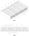
Fig. 1 illustrates a three-dimensional structure schematic diagram of a back-blowing unblocking device for a dustproof screen of a dryer according to an embodiment of the present invention applied to dustproof equipment; -
Fig. 2 illustrates a front view of the dustproof equipment inFig. 1 ; -
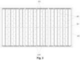
Fig. 3 illustrates a top view of the dustproof equipment inFig. 1 ; -
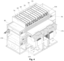
Fig. 4 illustrates a three-dimensional structure schematic diagram of a dryer according to an embodiment of the present invention applied to dustproof equipment; -
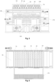
Fig. 5 illustrates a front view of the dryer inFig. 4 ; and -
Fig. 6 illustrates a top view of the dryer inFig. 4 . - The drawings include the following reference signs:
10, dustproof screen; 20, high-pressure air main pipe; 30, high-pressure air horizontal pipe; 40, high-pressure air branch pipe; 50, shunt connecting pipe; 60, back-blowing fan-shaped nozzle; 70, frame body; 80, material conveyor belt; 90, mesh structure; 91, through hole; 100, sub-dustproof component; 110, bracket; 111, first support plate body; 112, second support plate body; 120, first pressing plate; 130, second pressing plate; 140, crimping member; 150, base; 160, fan; 170, bag filter. - It is to be noted that embodiments in the present invention and characteristics in the embodiments may be combined under the condition of no conflicts. The present invention is described below with reference to the drawings and in conjunction with the embodiments in detail.
- It is to be noted that all technical and scientific terms used in the present invention have the same meaning as commonly understood by those of ordinary skill in the art to which the present invention belongs, unless otherwise indicated.
- In the present invention, if no explanation is made to the contrary, the orientation words used such as "up, down" usually refer to the direction shown in the drawings, or refer to the vertical, vertical or gravity direction. Similarly, for ease of understanding and description, "left, right" usually refers to the left and right shown in the drawings; "inner, outer" refers to the inner and outer parts relative to the contour of each component, but the above orientation words are not used to limit the present invention.
- In order to solve a problem in an art of increase of the labor intensity of workers caused by difficulty in cleaning a dustproof screen of a dryer, some embodiments of the present invention provide a back-blowing unblocking device for the dustproof screen of the dryer, a dustproof equipment, and a dryer.
- In some embodiments, the term "back-blowing" refers to blow in the direction opposite to a movement of dust.
- As shown in
Fig. 1 to Fig. 3 , a dryer dustproof screen back-blowing unblocking device fully utilizes a vacant closed compartment space of the dryer, a matching non-stop multi-row back-blowing dense spray high-pressure air unblocking device is added to thedustproof screen 10, and the back-blowing unblocking device for the dustproof screen of the dryer includes a high-pressure airmain pipe 20, a high-pressure airhorizontal pipe 30, high-pressureair branch pipes 40,shunt connecting pipes 50, and back-blowing fan-shaped nozzles 60. Except for the back-blowing fan-shaped nozzles 60, all others are welded and formed by stainless steel pipe materials, a length of each high-pressureair branch pipe 40 is equal to a length of an A-shapeddustproof screen 10, both ends of the each high-pressureair branch pipe 40 are closed and an upper center opening is welded to a correspondingshunt connecting pipe 50, both sides of the each high-pressureair branch pipe 40 are densely arranged with the back-blowing fan-shaped nozzles 60 to form a dense spray form, a row number of the high-pressureair branch pipes 40 is equal to a segment number of the A-shapeddustproof screen 10 to form a dense spray form, the back-blowing unblocking device for the dustproof screen of the dryer is mounted on thedustproof screen 10 to make the back-blowing fan-shaped nozzles 60 located between the two A-shapeddustproof screens 10, and the high-pressure airmain pipe 20 is connected with an air source valve through a hose. - Applying the technical solution of the present embodiment, the back-blowing unblocking device for the dustproof screen of the dryer includes the high-pressure air
main pipe 20, the high-pressure airhorizontal pipe 30, the high-pressureair branch pipes 40, theshunt connecting pipes 50, and the back-blowing fan-shaped nozzles 60. When thedustproof screen 10 needs to be cleaned, a worker turns on the air source valve so that gas enters the high-pressure airmain pipe 20 through the hose, and gas in the high-pressure airmain pipe 20 enters each shut connectingpipe 50 through the high-pressure airhorizontal pipe 30, and gas entering the eachshunt connecting pipe 50 enters the high-pressureair branch pipe 40, and is finally sprayed out through the back-blowing fan-shaped nozzles 60 to clean thedustproof screen 10. - Compared with the art known to inventors that requires manual cleaning of the dustproof screen, the back-blowing unblocking device for the dustproof screen of the dryer in some embodiments of the present invention can replace the manual cleaning of the
dustproof screen 10, thereby solving the problem in the art of increase of the labor intensity of workers caused by difficulty in cleaning the dustproof screen of the dryer, and reducing the labor intensity of the workers. Meanwhile, when thedustproof screen 10 needs to be cleaned, the worker does not need to remove the dustproof screen from the dryer, which further reduces the labor intensity of the worker. In addition, the back-blowing unblocking device for the dustproof screen of the dryer in some embodiments of the present embodiment fully cleans the dustproof screen at one time without multiple cleaning, which improves the cleaning efficiency of the back-blowing unblocking device. - In some embodiments of the present invention, the
dustproof screen 10 is cleaned by gas, or thedustproof screen 10 is cleaned by liquid, that is, liquid sequentially enters the high-pressure airmain pipe 20, the high-pressure airhorizontal pipe 30, the high-pressureair branch pipe 40 and theshunt connecting pipe 50, and is finally sprayed onto thedustproof screen 10 through the back-blowing fan-shapednozzles 60 to clean thedustproof screen 10. - In some embodiments of the present invention, a spray direction of the each back-blowing fan-shaped
nozzle 60 is a horizontal direction. - As shown in
Fig. 1 to Fig. 3 , one end of the high-pressure airmain pipe 20 is provided with an arc surface that coincides with an outer circle of the high-pressure airhorizontal pipe 30, and the other end of the high-pressure airmain pipe 20 is provided with two parallel threads. Both ends of the high-pressure airhorizontal pipe 30 are closed, an upper side of the high-pressure airhorizontal pipe 30 is provided with air intake holes that coincide with the high-pressure airmain pipe 20, and a lower side of the high-pressure airhorizontal pipe 30 is provided with evenly distributed shunt holes that coincide with theshunt connecting pipes 50. Both ends of the eachshunt connecting pipe 50 are provided with arc surfaces that coincide with the shunt holes and an air intake hole of the each high-pressure air branch pipe respectively. In this way, the above arrangement makes the disassembly and assembly of the high-pressure airmain pipe 20, the high-pressure airhorizontal pipe 30 and theshunt connecting pipes 50 easier and simpler, and reduces the difficulty of disassembly and assembly. - Specifically, one end of the high-pressure air
main pipe 20 is connected with the high-pressure airhorizontal pipe 30, and the other end of the high-pressure airmain pipe 20 is connected with the air source valve. The upper side of the high-pressure airhorizontal pipe 30 is connected with the high-pressure airmain pipe 20. The lower side of the high-pressure airhorizontal pipe 30 is connected with a plurality ofbranch connecting pipes 50, so that gas entering the high-pressure airhorizontal pipe 30 is shunted to eachshunt connecting pipe 50, thereby realizing an all-round cleaning of thedustproof screen 10 by the back-blowing unblocking device for the dustproof screen of the dryer, and improving the cleaning efficiency of the back-blowing unblocking device for the dustproof screen of the dryer. - As shown in
Fig. 1 to Fig. 3 , one end of each back-blowing fan-shapednozzle 60 is provided with an arc surface that coincides with an air outlet hole of the high-pressureair branch pipe 40, and the each back-blowing fan-shapednozzle 60 is welded to the air outlet hole. The other end of the each back-blowing fan-shapednozzle 60 is provided with a nozzle opening in a fan-shaped spray shape, the nozzle opening comprises a V-shaped groove to form the fan-shaped spray shape, and the nozzle opening has a spray angle of 60° and is machined by a stainless steel material. In this way, the above arrangement expands the spray range of the back-blowing fan-shapednozzles 60, and further improves the cleaning effect of thedustproof screen 10 by the back-blowing fan-shapednozzles 60. - As shown in
Fig. 4 to Fig. 6 , some embodiments of the present invention also provide a dustproof equipment, which includes aframe body 70, thedustproof screen 10, and the back-blowing unblocking device for the dustproof screen of the dryer located above thedustproof screen 10. Thedustproof screen 10 and the back-blowing unblocking device for the dustproof screen of the dryer are both disposed on theframe body 70. The dustproof equipment is located above amaterial conveyor belt 80. In a process of conveying materials of thematerial conveyor belt 80, a dry airflow is blown to the dustproof equipment by thematerial conveyor belt 80, so that dust generated in a drying process is attached to thedustproof screen 10. The back-blowing unblocking device for the dustproof screen of the dryer is the above dryer dustproof screen back-blowing unblocking device. In this way, the above arrangement ensures that the dustproof equipment collects dust and other impurities generated in a material drying process, and prevents the dust and other impurities from affecting a subsequent processing of materials. - In some embodiments, the
dustproof screen 10 is located above thematerial conveyor belt 80, and the back-blowing unblocking device for the dustproof screen of the dryer is located above thedustproof screen 10. Thematerial conveyor belt 80 conveys materials, and a dry airflow is blown to the dustproof equipment through thematerial conveyor belt 80, and impurities such as dust generated in the drying process are blown onto thedustproof screen 10, thereby preventing impurities such as dust from entering a working environment. When thedustproof screen 10 needs to be cleaned, a worker operates an air source valve so that gas or liquid sequentially enters the high-pressure air main 20, the high-pressure airhorizontal pipe 30, the high-pressureair branch pipe 40 and theshunt connecting pipe 50, and is finally sprayed onto thedustproof screen 10 through the back-blowing fan-shapednozzle 60 to clean thedustproof screen 10, thereby solving the problem in the art of increase of the labor intensity of workers caused by difficulty in cleaning a dustproof screen of a dryer, and reducing the labor intensity of the workers. Meanwhile, when thedustproof screen 10 needs to be cleaned, the worker does not need to remove the dustproof screen from the dryer, which further reduces the labor intensity of the worker. - As shown in
Fig. 1, Fig. 2 andFig. 4 , the dustproof device further includes amesh structure 90. Themesh structure 90 is located below thedustproof screen 10. Themesh structure 90 has a plurality of throughholes 91 for the passage of the dust. In this way, in the process of drying materials by a dry airflow, impurities such as dust pass through the throughhole 91 and then are attached to thedustproof screen 10. On the one hand, it is ensured that the dust and other impurities are attached to thedustproof screen 10 to prevent dust from flying. On the one hand, impurities such as dust attached to thedustproof screen 10 are prevented from falling on thematerial conveying belt 80 again. - In some embodiments of the present invention, the dustproof equipment further includes a control device. The dryer dustproof screen back-blowing unblocking device has a back-blowing state in which a back-blowing fan-shaped
nozzle 60 sprays gas or liquid to thedustproof screen 10 and a non-working state in which the back-blowing fan-shapednozzle 60 does not spray gas or liquid, and the control device is connected with an air source valve of the back-blowing unblocking device for the dustproof screen of the dryer to control a working state of the air source valve to make the back-blowing unblocking device for the dustproof screen of the dryer switched between the back-blowing state and the non-working state. When thematerial conveyor belt 80 conveys materials, the control device controls the back-blowing unblocking device for the dustproof screen of the dryer to be in the non-working state. In this way, the above arrangement makes it easier and convenient for workers to operate the back-blowing unblocking device for the dustproof screen of the dryer, reduces the difficulty of control, and reduces the labor intensity of the workers. - Specifically, when the
material conveyor belt 80 conveys materials, the dry airflow is blown toward the materials to dry the materials, and at this time, the back-blowing unblocking device for the dustproof screen of the dryer is in the non-working state. After the dry airflow completes the drying operation on the materials and thedustproof screen 10 needs to be cleaned, the control device controls the back-blowing fan-shapednozzles 60 so that the back-blowing fan-shapednozzles 60 spray gas or liquid to thedustproof screen 10, and the back-blowing unblocking device for the dustproof screen of the dryer is in the back-blowing state to clean thedustproof screen 10. - As shown in
Fig. 1 to Fig. 6 , the dustproof equipment includes a plurality ofsub-dustproof assemblies 100. The plurality ofsub-dustproof assemblies 100 are disposed at intervals in a conveying direction of thematerial conveyor belt 80. Each of the plurality ofsub-dustproof assemblies 100 includes abracket 110. Thebracket 110 includes a firstsupport plate body 111 and a secondsupport plate body 112. The firstsupport plate body 111 and the secondsupport plate body 112 are arranged at an angle. Onedustproof screen 10 is laid on the firstsupport plate body 111, and anotherdustproof screen 10 is laid on the secondsupport plate body 112. In this way, the above arrangement makes the mounting of thedustproof screen 10 and thebracket 110 easier and simpler, and reduces the difficulty in disassembly and assembly. Meanwhile, the above arrangement of the firstsupport plate body 111 and the secondsupport plate body 112 increase the contact area between thedustproof screen 10 and dust, thereby ensuring that the dust is attached to thedustproof screen 10. Meanwhile, the above structure is simple, processing and implementation are facilitated, and the processing cost of the dustproof equipment is reduced. - As shown in
Fig. 1, Fig. 2 ,Fig. 4 andFig. 5 , thebracket 110 is of an inverted V-shaped structure. In this way, on the one hand, the above arrangement makes the structure of the eachsub-dustproof assembly 100 more stable, and avoids affecting the structural stability of the dustproof equipment due to displacement of thesub-dustproof assembly 100 under an action of the dry airflow. On the other hand, the above arrangement increases the contact area between thedustproof screen 10 and the dust, thereby ensuring that the dust can be completely attached to thedustproof screen 10. - As shown in
Fig. 1 and Fig. 2 , each of thesub-dustproof assemblies 100 further includes a firstpressing plate 120, a secondpressing plate 130 and a crimping member. The firstpressing plate 120 presses onedustproof screen 10 on the firstsupport plate body 111. The secondpressing plate 130 presses onedustproof screen 10 on the secondsupport plate body 112. The adjacent firstpressing plate 120 and the secondpressing plate 130 are connected through the crimpingmember 140. In this way, the above arrangement makes the disassembly and assembly of thedustproof screen 10 and thebracket 110 easier and simpler, also improves the connection stability of thebracket 110 and thedustproof screen 10, and avoids affecting the dust suction effect of the dustproof equipment due to displacement of thedustproof screen 10. - In some embodiments of the present invention, a first end of the first
support plate body 111 and a first end of the secondsupport plate body 112 form a first opening, a second end of the firstsupport plate body 111 and a second end of the secondsupport plate body 112 form a second opening, and the first opening and the second opening are provided with the dustproof screens 10. In this way, the above arrangement further increases the area of thedustproof screen 10, thereby ensuring that dust is sufficiently attached to thedustproof screen 10, and improving the dust suction effect of the dustproof equipment. - In other implementation manners not shown in the drawings, the first end of the first support plate body and the first end of the second support plate body form a first opening, and the first opening is provided with the dustproof screen. In this way, the above arrangement further increases the area of the dustproof screen, thereby ensuring that dust is sufficiently attached to the dustproof screen, and improving the dust suction effect of the dustproof equipment.
- In other implementation manners not shown in the drawings, the second end of the first support plate body and the second end of the second support plate body form a second opening, and the second opening is provided with the dustproof screen. In this way, the above arrangement further increases the area of the dustproof screen, thereby ensuring that dust is sufficiently attached to the dustproof screen, and improving the dust suction effect of the dustproof equipment.
- In some embodiments of the present invention, the
dustproof screen 10 is a filter screen. In some embodiments, the filter screen is made of nylon or stainless steel. In this way, the above arrangement reduces a processing cost of thedustproof screen 10, and further reduces the processing cost of the dustproof equipment. - As shown in
Fig. 4 to Fig. 6 , some embodiments of the present invention also provide a dryer, which includes abase 150, afan 160, amaterial conveyor belt 80, abag filter 170, and the dustproof equipment. Thefan 160, thematerial conveyor belt 80, thebag filter 170 and the dustproof equipment are all disposed on thebase 150, thematerial conveyor belt 80 is located between thefan 160 and the dustproof equipment in a height direction of the dryer, and thefan 160 is located below thematerial conveyor belt 80. The dustproof equipment is the above dustproof equipment. In this way, when the dryer is dehumidifying and drying materials, thefan 160 blows dry hot air toward thematerial conveyor belt 80 and the dustproof equipment, so that dust and other impurities generated in the drying process are attached to thedustproof screen 10 to avoid dust flying in the working environment and affecting the health of workers. - In some embodiments, the dryer is a closed low-temperature filter cake dryer.
- Specifically, the working principle of the dryer is as follows: a material (filter cake) is conveyed to a filter cake slitting device of the dryer through a conveyor belt, and continuously falls onto a first layer of material conveyor belt 80 (located at a low position) in a closed chamber of the dryer after crushing and slitting. The air conditioning heating or hot water coil of a thermal circulation mechanism forms a high-temperature environment of about 65-80°C. The
fan 160 provides convective hot air to dry a long filter cake at high temperature. The dried filter cake is transported to a second layer of material conveyor belt 80 (located at a high position), thedustproof screen 10 intercepts dust, the back-blowing unblocking device for the dustproof screen of the dryer cleans thedustproof screen 10, a circulating air cooler of the dryer performs condensation and dehumidification at a low temperature around 25°C, condensed water flows out by own weight, and finally the filter cake with qualified moisture content is transported to a dry silo with a wire mesh conveyor belt. The machine has a moisture content of 55-83% in the feed and a moisture content of 3-50% in the discharge, and is freely adjustable. The dryer in some embodiments of the present invention is energy-saving and environmentally friendly, and has the advantages of good filter cake drying effect, high production efficiency, and no filter cake dust hazard. - From the above description, it can be seen that the above embodiments of the present invention achieve the following technical effects:
The back-blowing unblocking device for the dustproof screen of the dryer includes a high-pressure air main pipe, a high-pressure air horizontal pipe, high-pressure air branch pipes, shunt connecting pipes, and back-blowing fan-shaped nozzles. When a dustproof screen needs to be cleaned, a worker turns on an air source valve so that gas enters the high-pressure air main pipe through a hose, and gas in the high-pressure air main pipe enters each shut connecting pipe through the high-pressure air horizontal pipe, and gas entering the each shunt connecting pipe enters the high-pressure air branch pipe, and is finally sprayed out through the back-blowing fan-shaped nozzles to clean the dustproof screen. - Compared with the art that requires manual cleaning of the dustproof screen, the back-blowing unblocking device for the dustproof screen of the dryer in some embodiments of the present invention replaces the manual cleaning of the dustproof screen, thereby solving the problem in the art known to inventors of increase of the labor intensity of workers caused by difficulty in cleaning a dustproof screen of a dryer, and reducing the labor intensity of the workers. Meanwhile, when the dustproof screen needs to be cleaned, the worker does not need to remove the dustproof screen from the dryer, which further reduces the labor intensity of the worker. In addition, the back-blowing unblocking device for the dustproof screen of the dryer in some embodiments of the present invention fully cleans the dustproof screen at one time without multiple cleaning, which improves the cleaning efficiency of the back-blowing unblocking device for the dustproof screen of the dryer.
- It is apparent that the described embodiments are only part of the embodiments of the present invention, not all of the embodiments. All other embodiments obtained by those of ordinary skill in the art based on the embodiments of the invention without creative efforts should fall within the scope of protection of the invention.
- It is to be noted that terms used herein only aim to describe specific implementation manners, and are not intended to limit exemplar implementations of this invention. Unless otherwise directed by the context, singular forms of terms used herein are intended to include plural forms. Besides, it will be also appreciated that when terms "contain" and/or "include" are used in the description, it is indicated that features, steps, operations, devices, assemblies and/or a combination thereof exist.
- It is to be noted that the specification and claims of the invention and the terms "first", "second" and the like in the drawings are used to distinguish similar objects, and do not need to describe a specific sequence or a precedence order. It will be appreciated that data used in such a way may be exchanged under appropriate conditions, in order that the embodiments of the present invention described here can be implemented in a sequence other than sequences graphically shown or described here.
- The above is only some embodiments of the present invention, not intended to limit the present invention. As will occur to those skilled in the art, the present invention is susceptible to various modifications and changes falling within the scope of the appended claims.
Claims (10)
- A dustproof equipment, comprising a frame body (70), a dustproof screen (10), and a back-blowing unblocking device for the dustproof screen of a dryer, wherein the back-blowing unblocking device is located above the dustproof screen (10), the dustproof screen (10) and the back-blowing unblocking device for the dustproof screen of the dryer are both disposed on the frame body (70), in a process of conveying materials of the material conveyor belt (80), a dry airflow is blown to the dustproof equipment by the material conveyor belt (80), so that dust generated in a drying process is attached to the dustproof screen (10), the back-blowing unblocking device for the dustproof screen of the dryer, fully utilizing a vacant closed compartment space of the dryer, a matching non-stop multi-row back-blowing spray high-pressure air unblocking device being added to the dustproof screen (10), the back-blowing unblocking device for the dustproof screen of the dryer comprising a high-pressure air main pipe (20), a high-pressure air horizontal pipe (30), a shunt connecting pipe (50), and back-blowing fan-shaped nozzles (60), and the high-pressure air main pipe (20) is connected with an air source valve through a hose;
characterized in that,the back-blowing unblocking device for the dustproof screen of the dryer comprises high-pressure air branch pipes (40), a length of each high-pressure air branch pipe (40) is equal to a length of an A-shaped dustproof screen (10), both ends of the each high-pressure air branch pipe (40) are closed and an upper center opening is welded to the shunt connecting pipe (50), both sides of the each high-pressure air branch pipe (40) are arranged with the back-blowing fan-shaped nozzles (60), and the back-blowing fan-shaped nozzles (60) are evenly arranged in an interlaced form, a row number of the high-pressure air branch pipes (40) is equal to a segment number of the A-shaped dustproof screen (10), the back-blowing unblocking device for the dustproof screen of the dryer is mounted on the dustproof screen (10) to make the back-blowing fan-shaped nozzles (60) located between the two A-shaped dustproof screens (10);except for the back-blowing fan-shaped nozzles (60), all others are welded and formed by stainless steel pipe materials;the dustproof equipment is located above a material conveyor belt (80);the dustproof equipment comprises a plurality of sub-dustproof assemblies (100), the plurality of sub-dustproof assemblies (100) being disposed at intervals in a conveying direction of the material conveyor belt (80), each of the sub-dustproof assemblies (100) comprising:
a bracket (110), the bracket (110) comprising a first support plate body (111) and a second support plate body (112), the first support plate body (111) and the second support plate body (112) being disposed at an angle, one dustproof screen (10) being laid on the first support plate body (111), and another dustproof screen (10) being laid on the second support plate body (112). - The dustproof equipment as claimed in claim 1, wherein one end of the high-pressure air main pipe (20) is provided with an arc surface that coincides with an outer circle of the high-pressure air horizontal pipe (30), and the other end of the high-pressure air main pipe (20) is provided with two parallel threads; both ends of the high-pressure air horizontal pipe (30) are closed, an upper side of the high-pressure air horizontal pipe (30) is provided with an air intake hole that coincide with the high-pressure air main pipe (20), and a lower side of the high-pressure air horizontal pipe (30) is provided with evenly distributed shunt holes that coincide with shunt connecting pipes (50); and both ends of each of the shunt connecting pipes (50) are provided with arc surfaces that coincide with the shunt holes and the air intake hole respectively.
- The dustproof equipment as claimed in claim 1, wherein one end of the back-blowing fan-shaped nozzle (60) is provided with an arc surface that coincides with an air outlet hole of the high-pressure air branch pipe (40), and the back-blowing fan-shaped nozzle (60) is welded to the air outlet hole; and the other end of the back-blowing fan-shaped nozzle (60) is provided with a nozzle opening in a fan-shaped spray shape, the nozzle opening comprises a V-shaped groove to form the fan-shaped spray shape, and the nozzle opening has a spray angle of 60° and is machined by a stainless steel material.
- The dustproof equipment as claimed in claim 1, further comprising:
a mesh structure (90), located below the dustproof screen (10), the mesh structure (90) comprising a plurality of through holes (91) for a passage of the dust. - The dustproof equipment as claimed in claim 1, further comprising:
a control device, wherein the back-blowing unblocking device for the dustproof screen of the dryer has a back-blowing state in which the back-blowing fan-shaped nozzle (60) sprays gas or liquid to the dustproof screen (10) and a non-working state in which the back-blowing fan-shaped nozzle (60) does not spray gas or liquid, the control device is connected with an air source valve of the back-blowing unblocking device for the dustproof screen of the dryer to control a working state of the air source valve to make the back-blowing unblocking device for the dustproof screen of the dryer switched between the back-blowing state and the non-working state, and when the material conveyor belt (80) conveys materials, the control device controls the back-blowing unblocking device for the dustproof screen of the dryer to be in the non-working state. - The dustproof equipment as claimed in claim 5, wherein the bracket (110) is of an inverted V-shaped structure.
- The dustproof equipment as claimed in claim 5, wherein each of the sub-dustproof assemblies (100) comprises:a first pressing plate (120), the first pressing plate (120) pressing one dustproof screen (10) on the first support plate body (111);a second pressing plate (130), the second pressing plate (130) pressing one dustproof screen (10) on the second support plate body (112); anda crimping member (140), the adjacent first pressing plate (120) and the second pressing plate (130) being connected through the crimping member (140).
- The dustproof equipment as claimed in claim 5, wherein a first end of the first support plate body (111) and a first end of the second support plate body (112) form a first opening, a second end of the first support plate body (111) and a second end of the second support plate body (112) form a second opening, and the first opening and/or the second opening are provided with the dustproof screens (10).
- The dustproof equipment as claimed in claim 5, wherein the dustproof screen (10) is a filter screen, and the filter screen is made of nylon or stainless steel.
- A dryer, comprising a base (150), a fan (160), the material conveyor belt (80), a bag filter (170), and the dustproof equipment as claimed in any one of claims 1 to 9, wherein the fan (160), the material conveyor belt (80), the bag filter (170) and the dustproof equipment are all disposed on the base (150), the material conveyor belt (80) is located between the fan (160) and the dustproof equipment in a height direction of the dryer, and the fan (160) is located below the material conveyor belt (80).
Applications Claiming Priority (2)
| Application Number | Priority Date | Filing Date | Title |
|---|---|---|---|
| CN201921357037 | 2019-08-21 | ||
| PCT/CN2020/075864 WO2021031539A1 (en) | 2019-08-21 | 2020-02-19 | Blowback blockage removing apparatus for drying machine dust screen, dust-proof device, and drying machine |
Publications (3)
| Publication Number | Publication Date |
|---|---|
| EP3799945A1 EP3799945A1 (en) | 2021-04-07 |
| EP3799945A4 EP3799945A4 (en) | 2022-05-04 |
| EP3799945B1 true EP3799945B1 (en) | 2024-07-17 |
Family
ID=70867845
Family Applications (1)
| Application Number | Title | Priority Date | Filing Date |
|---|---|---|---|
| EP20785895.2A Active EP3799945B1 (en) | 2019-08-21 | 2020-02-19 | Blowback blockage removing apparatus for drying machine dust screen, dust-proof device, and drying machine |
Country Status (8)
| Country | Link |
|---|---|
| US (1) | US11852410B2 (en) |
| EP (1) | EP3799945B1 (en) |
| JP (1) | JP7152584B2 (en) |
| CN (2) | CN111228904A (en) |
| AU (1) | AU2020332844B2 (en) |
| RU (1) | RU2753852C1 (en) |
| WO (1) | WO2021031539A1 (en) |
| ZA (1) | ZA202203265B (en) |
Families Citing this family (14)
| Publication number | Priority date | Publication date | Assignee | Title |
|---|---|---|---|---|
| CN111228904A (en) * | 2019-08-21 | 2020-06-05 | 景津环保股份有限公司 | Reverse blowing and blockage removing device for dust screen of dryer and corresponding closed dryer |
| CN111578670B (en) * | 2020-05-15 | 2021-10-19 | 广州金鹏环保工程有限公司 | A material drying and cooling integrated machine |
| CN111707085A (en) * | 2020-07-13 | 2020-09-25 | 广州金鹏环保工程有限公司 | New environmentally friendly feed drying and cooling integrated machine |
| CN113532095A (en) * | 2021-05-24 | 2021-10-22 | 广东省现代农业装备研究所 | An integrated method for liquid heat recovery and impurity removal |
| CN113305042A (en) * | 2021-06-02 | 2021-08-27 | 安徽捷迅光电技术有限公司 | Automatic dust removal structure of dust collection pipe of color sorter |
| CN114543491A (en) * | 2022-02-23 | 2022-05-27 | 林耀耿 | Screening and drying device for processing Chinese herbal medicine decoction pieces |
| CN114433479A (en) * | 2022-03-14 | 2022-05-06 | 浙江科特高温新材料有限公司 | Equipment for producing high-strength corundum impact brick for long-life carbon-free steel ladle |
| CN114748945A (en) * | 2022-04-28 | 2022-07-15 | 湖南迎春思博瑞智能装备有限公司 | Dust suppression conveyor |
| CN114768414A (en) * | 2022-05-15 | 2022-07-22 | 景津装备股份有限公司 | Vibration net blockage-removing integrated heat exchange chamber dust screen device and closed filter cake dryer |
| CN115193885B (en) * | 2022-07-11 | 2023-06-30 | 景津装备股份有限公司 | Two-way pre-cutting and homogenizing device for large filter cakes and secondary filter cake crushing and slitter mechanism |
| KR20250151448A (en) * | 2023-05-17 | 2025-10-21 | 주식회사 히타치하이테크 | Automatic Analysis System |
| CN116906374B (en) * | 2023-08-21 | 2024-03-22 | 苏州顶裕节能设备有限公司 | Air conditioning device and centrifugal blower |
| CN118382277B (en) * | 2024-06-26 | 2024-09-20 | 朗盛技术有限公司 | Dust filtering and ventilating device for communication base station room |
| CN118681337B (en) * | 2024-08-22 | 2024-11-19 | 苏州国立洁净技术有限公司 | Back-blowing cleaning structure, air filter based on the cleaning structure, and filtering method |
Family Cites Families (28)
| Publication number | Priority date | Publication date | Assignee | Title |
|---|---|---|---|---|
| US3620234A (en) * | 1969-07-07 | 1971-11-16 | Herbert L Everrood | Air-filter-cleaning apparatus |
| SE400479B (en) * | 1974-11-08 | 1978-04-03 | Atlas Copco Ab | KIT AND DEVICE FOR CLEANING DUST SEPARATION FILTER |
| DE2730925A1 (en) * | 1977-07-08 | 1979-01-25 | Heinz Hoelter | Filter of small construction for mining and tunnelling - having fabric medium mounted in V=form |
| US4445559A (en) * | 1983-04-18 | 1984-05-01 | Balfour Lumber Company | Water fog-type ash precipitator for a kilned lumber pile breakdown hoist |
| EP0225613A3 (en) * | 1985-12-10 | 1988-06-22 | Gebrueder Buehler Ag Maschinenfabrik | Filter for air and gases |
| US5143528A (en) * | 1990-02-14 | 1992-09-01 | Challenge Industries | Lint collector |
| RU2004899C1 (en) * | 1990-05-07 | 1993-12-15 | Акционерное общество "Белгородский завод энергетического машиностроени " | Article outer surface cleaning device |
| US5156660A (en) * | 1991-06-28 | 1992-10-20 | Wilson James H | Filter cleaning apparatus |
| JPH072001A (en) | 1991-09-24 | 1995-01-06 | Suzuki Motor Corp | Seat adjuster |
| SE507239C2 (en) * | 1996-01-23 | 1998-04-27 | Flaekt Ab | Device for cleaning filter elements |
| US20020179522A1 (en) * | 2001-03-22 | 2002-12-05 | Phillips Terrance D. | Sintered metal HEPA filter to block release of mercury |
| US6421931B1 (en) * | 2001-05-08 | 2002-07-23 | Daniel R Chapman | Method and apparatus for drying iron ore pellets |
| RU2267073C2 (en) * | 2003-12-25 | 2005-12-27 | ОАО "Красноярскэнерго" | Device for water-jet treatment of furnace walls in power generating boilers |
| RU2340856C2 (en) * | 2004-04-23 | 2008-12-10 | ООО "Промтехэксперт" | Plant for gas-impulsive cleaning of heating surfaces |
| DE102009023359A1 (en) * | 2008-08-18 | 2010-02-25 | Sms Siemag Ag | Method and device for cooling and drying a hot strip or sheet in a rolling mill |
| DE202010017403U1 (en) * | 2009-10-19 | 2011-10-27 | Jnw Cleaningsolutions Gmbh | Cleaning device for heat exchangers with conductors |
| CN202539052U (en) * | 2012-01-16 | 2012-11-21 | 石家庄功倍重型机械有限公司 | Pulse jet cleaning screening machine |
| RU123509U1 (en) * | 2012-02-27 | 2012-12-27 | Открытое акционерное общество "Научно-производственное объединение по исследованию и проектированию энергетического оборудования им. И.И. Ползунова" (ОАО "НПО ЦКТИ") | DEVICE FOR PULSE CLEANING OF HEATING SURFACES FROM EXTERNAL DEPOSITS |
| DOP2012000311A (en) * | 2012-12-12 | 2014-06-15 | Jose Roberto Ortiz Lara | AUTOMATED ELECTRONIC DYEING AND DRYING NAIL DEVICE |
| US20160101443A1 (en) * | 2014-09-18 | 2016-04-14 | Gordon Andrew Christensen | Separator and Dryer for Ammunition Casings and Cleaning Media |
| CN105617788A (en) | 2016-02-05 | 2016-06-01 | 湖南升华科技股份有限公司 | Rapid cleaning device of vacuum dryer filter screen, vacuum dryer filter unit and vacuum dryer filter screen cleaning method |
| CN106318472B (en) * | 2016-11-01 | 2019-03-12 | 中国科学院过程工程研究所 | A high-temperature dust-laden gas dedusting device |
| CN106823568B (en) * | 2017-04-06 | 2020-02-18 | 景津环保股份有限公司 | Device and method for automatically cleaning filter plate |
| CN207422843U (en) | 2017-10-24 | 2018-05-29 | 景津环保股份有限公司 | A kind of high temperature and low temperature filtration cakes torrefaction machine |
| WO2019117370A1 (en) * | 2017-12-14 | 2019-06-20 | 디에이치테크 주식회사 | Cassette-type filter device |
| CN107899325A (en) * | 2017-12-15 | 2018-04-13 | 山东钢铁股份有限公司 | A kind of sintering machine tail Flash Gas Compression Skid System |
| CN109011894A (en) * | 2018-09-04 | 2018-12-18 | 江苏人和环保设备有限公司 | A kind of fast-connecting type injection tube for deduster |
| CN111228904A (en) * | 2019-08-21 | 2020-06-05 | 景津环保股份有限公司 | Reverse blowing and blockage removing device for dust screen of dryer and corresponding closed dryer |
-
2020
- 2020-02-19 CN CN202010101587.0A patent/CN111228904A/en not_active Withdrawn
- 2020-02-19 RU RU2020143151A patent/RU2753852C1/en active
- 2020-02-19 EP EP20785895.2A patent/EP3799945B1/en active Active
- 2020-02-19 WO PCT/CN2020/075864 patent/WO2021031539A1/en not_active Ceased
- 2020-02-19 US US17/042,137 patent/US11852410B2/en active Active
- 2020-02-19 JP JP2021500527A patent/JP7152584B2/en active Active
- 2020-02-19 CN CN202020183626.1U patent/CN211799422U/en active Active
- 2020-02-19 AU AU2020332844A patent/AU2020332844B2/en active Active
-
2022
- 2022-03-18 ZA ZA2022/03265A patent/ZA202203265B/en unknown
Also Published As
| Publication number | Publication date |
|---|---|
| EP3799945A1 (en) | 2021-04-07 |
| CN211799422U (en) | 2020-10-30 |
| CN111228904A (en) | 2020-06-05 |
| WO2021031539A1 (en) | 2021-02-25 |
| EP3799945A4 (en) | 2022-05-04 |
| ZA202203265B (en) | 2023-11-29 |
| AU2020332844B2 (en) | 2024-02-22 |
| US20230141778A1 (en) | 2023-05-11 |
| JP7152584B2 (en) | 2022-10-12 |
| AU2020332844A1 (en) | 2022-04-21 |
| US11852410B2 (en) | 2023-12-26 |
| RU2753852C1 (en) | 2021-08-24 |
| JP2022501171A (en) | 2022-01-06 |
Similar Documents
| Publication | Publication Date | Title |
|---|---|---|
| US11852410B2 (en) | Back-blowing unblocking device for dustproof screen of dryer, dustproof equipment, and dryer | |
| CN206474356U (en) | A kind of full-automatic controllable spray painting production system | |
| US20150260455A1 (en) | Method for filtering an air flow in a grain dryer | |
| CN206853353U (en) | Water film type air cleaner | |
| CN208844229U (en) | A kind of novel dried modular system of chemical fibre | |
| CN112452612A (en) | Spraying device for fan blade production and processing | |
| CN105627713B (en) | A kind of band drier | |
| CN208800477U (en) | Cleaning device is used in a kind of production of chain | |
| CN107990634B (en) | Drying apparatus | |
| CN204866318U (en) | Automatic drying device sprays paint | |
| CN209237619U (en) | A kind of plastics dust processing device | |
| CN103736682A (en) | Pass-type high-pressure water spraying cleaning machine | |
| CN217287680U (en) | Dust screen lifting type reverse blowing blockage removal device and corresponding closed filter cake dryer | |
| CN216558166U (en) | High-efficiency energy-saving oven | |
| CN105921481B (en) | Vibrating screen dust settler and vibrating screen dust pelletizing system | |
| CN113617153B (en) | High-efficient phase transition dust removal defogging system | |
| CN109371591A (en) | A kind of textile fabric additive spray drying equipment | |
| CN104101031A (en) | Air drier applicable to dusty environment | |
| KR101085098B1 (en) | Multi nozzle cleaning gun for heat exchanger and cleaning system using same | |
| CN223833029U (en) | A pipe unclogging device for an integrated denitrification system | |
| CN210569771U (en) | Hot air drying oven | |
| CN223452783U (en) | Linear blow-drying device for lettuce | |
| CN217141014U (en) | Moisture drying room for paint spraying production line | |
| CN210320884U (en) | A heat pump dehumidification box dryer | |
| CN109680132A (en) | The rapid cooling system of isothermal normalizing production line |
Legal Events
| Date | Code | Title | Description |
|---|---|---|---|
| STAA | Information on the status of an ep patent application or granted ep patent |
Free format text: STATUS: UNKNOWN |
|
| STAA | Information on the status of an ep patent application or granted ep patent |
Free format text: STATUS: THE INTERNATIONAL PUBLICATION HAS BEEN MADE |
|
| PUAI | Public reference made under article 153(3) epc to a published international application that has entered the european phase |
Free format text: ORIGINAL CODE: 0009012 |
|
| STAA | Information on the status of an ep patent application or granted ep patent |
Free format text: STATUS: REQUEST FOR EXAMINATION WAS MADE |
|
| 17P | Request for examination filed |
Effective date: 20201014 |
|
| AK | Designated contracting states |
Kind code of ref document: A1 Designated state(s): AL AT BE BG CH CY CZ DE DK EE ES FI FR GB GR HR HU IE IS IT LI LT LU LV MC MK MT NL NO PL PT RO RS SE SI SK SM TR |
|
| AX | Request for extension of the european patent |
Extension state: BA ME |
|
| RAP3 | Party data changed (applicant data changed or rights of an application transferred) |
Owner name: JINGJIN EQUIPMENT INC. |
|
| A4 | Supplementary search report drawn up and despatched |
Effective date: 20220404 |
|
| RIC1 | Information provided on ipc code assigned before grant |
Ipc: B01D 46/10 20060101AFI20220328BHEP |
|
| DAV | Request for validation of the european patent (deleted) | ||
| DAX | Request for extension of the european patent (deleted) | ||
| GRAP | Despatch of communication of intention to grant a patent |
Free format text: ORIGINAL CODE: EPIDOSNIGR1 |
|
| STAA | Information on the status of an ep patent application or granted ep patent |
Free format text: STATUS: GRANT OF PATENT IS INTENDED |
|
| INTG | Intention to grant announced |
Effective date: 20240425 |
|
| GRAS | Grant fee paid |
Free format text: ORIGINAL CODE: EPIDOSNIGR3 |
|
| GRAA | (expected) grant |
Free format text: ORIGINAL CODE: 0009210 |
|
| STAA | Information on the status of an ep patent application or granted ep patent |
Free format text: STATUS: THE PATENT HAS BEEN GRANTED |
|
| AK | Designated contracting states |
Kind code of ref document: B1 Designated state(s): AL AT BE BG CH CY CZ DE DK EE ES FI FR GB GR HR HU IE IS IT LI LT LU LV MC MK MT NL NO PL PT RO RS SE SI SK SM TR |
|
| REG | Reference to a national code |
Ref country code: CH Ref legal event code: EP |
|
| REG | Reference to a national code |
Ref country code: DE Ref legal event code: R096 Ref document number: 602020034187 Country of ref document: DE |
|
| REG | Reference to a national code |
Ref country code: IE Ref legal event code: FG4D |
|
| REG | Reference to a national code |
Ref country code: LT Ref legal event code: MG9D |
|
| REG | Reference to a national code |
Ref country code: NL Ref legal event code: MP Effective date: 20240717 |
|
| PG25 | Lapsed in a contracting state [announced via postgrant information from national office to epo] |
Ref country code: PT Free format text: LAPSE BECAUSE OF FAILURE TO SUBMIT A TRANSLATION OF THE DESCRIPTION OR TO PAY THE FEE WITHIN THE PRESCRIBED TIME-LIMIT Effective date: 20241118 |
|
| REG | Reference to a national code |
Ref country code: AT Ref legal event code: MK05 Ref document number: 1703610 Country of ref document: AT Kind code of ref document: T Effective date: 20240717 |
|
| PG25 | Lapsed in a contracting state [announced via postgrant information from national office to epo] |
Ref country code: NL Free format text: LAPSE BECAUSE OF FAILURE TO SUBMIT A TRANSLATION OF THE DESCRIPTION OR TO PAY THE FEE WITHIN THE PRESCRIBED TIME-LIMIT Effective date: 20240717 |
|
| PG25 | Lapsed in a contracting state [announced via postgrant information from national office to epo] |
Ref country code: PT Free format text: LAPSE BECAUSE OF FAILURE TO SUBMIT A TRANSLATION OF THE DESCRIPTION OR TO PAY THE FEE WITHIN THE PRESCRIBED TIME-LIMIT Effective date: 20241118 Ref country code: NL Free format text: LAPSE BECAUSE OF FAILURE TO SUBMIT A TRANSLATION OF THE DESCRIPTION OR TO PAY THE FEE WITHIN THE PRESCRIBED TIME-LIMIT Effective date: 20240717 |
|
| PG25 | Lapsed in a contracting state [announced via postgrant information from national office to epo] |
Ref country code: NO Free format text: LAPSE BECAUSE OF FAILURE TO SUBMIT A TRANSLATION OF THE DESCRIPTION OR TO PAY THE FEE WITHIN THE PRESCRIBED TIME-LIMIT Effective date: 20241017 |
|
| PG25 | Lapsed in a contracting state [announced via postgrant information from national office to epo] |
Ref country code: GR Free format text: LAPSE BECAUSE OF FAILURE TO SUBMIT A TRANSLATION OF THE DESCRIPTION OR TO PAY THE FEE WITHIN THE PRESCRIBED TIME-LIMIT Effective date: 20241018 Ref country code: PL Free format text: LAPSE BECAUSE OF FAILURE TO SUBMIT A TRANSLATION OF THE DESCRIPTION OR TO PAY THE FEE WITHIN THE PRESCRIBED TIME-LIMIT Effective date: 20240717 Ref country code: FI Free format text: LAPSE BECAUSE OF FAILURE TO SUBMIT A TRANSLATION OF THE DESCRIPTION OR TO PAY THE FEE WITHIN THE PRESCRIBED TIME-LIMIT Effective date: 20240717 |
|
| PG25 | Lapsed in a contracting state [announced via postgrant information from national office to epo] |
Ref country code: BG Free format text: LAPSE BECAUSE OF FAILURE TO SUBMIT A TRANSLATION OF THE DESCRIPTION OR TO PAY THE FEE WITHIN THE PRESCRIBED TIME-LIMIT Effective date: 20240717 |
|
| PG25 | Lapsed in a contracting state [announced via postgrant information from national office to epo] |
Ref country code: LV Free format text: LAPSE BECAUSE OF FAILURE TO SUBMIT A TRANSLATION OF THE DESCRIPTION OR TO PAY THE FEE WITHIN THE PRESCRIBED TIME-LIMIT Effective date: 20240717 |
|
| PG25 | Lapsed in a contracting state [announced via postgrant information from national office to epo] |
Ref country code: IS Free format text: LAPSE BECAUSE OF FAILURE TO SUBMIT A TRANSLATION OF THE DESCRIPTION OR TO PAY THE FEE WITHIN THE PRESCRIBED TIME-LIMIT Effective date: 20241117 Ref country code: AT Free format text: LAPSE BECAUSE OF FAILURE TO SUBMIT A TRANSLATION OF THE DESCRIPTION OR TO PAY THE FEE WITHIN THE PRESCRIBED TIME-LIMIT Effective date: 20240717 |
|
| PG25 | Lapsed in a contracting state [announced via postgrant information from national office to epo] |
Ref country code: HR Free format text: LAPSE BECAUSE OF FAILURE TO SUBMIT A TRANSLATION OF THE DESCRIPTION OR TO PAY THE FEE WITHIN THE PRESCRIBED TIME-LIMIT Effective date: 20240717 |
|
| PG25 | Lapsed in a contracting state [announced via postgrant information from national office to epo] |
Ref country code: ES Free format text: LAPSE BECAUSE OF FAILURE TO SUBMIT A TRANSLATION OF THE DESCRIPTION OR TO PAY THE FEE WITHIN THE PRESCRIBED TIME-LIMIT Effective date: 20240717 Ref country code: RS Free format text: LAPSE BECAUSE OF FAILURE TO SUBMIT A TRANSLATION OF THE DESCRIPTION OR TO PAY THE FEE WITHIN THE PRESCRIBED TIME-LIMIT Effective date: 20241017 |
|
| PG25 | Lapsed in a contracting state [announced via postgrant information from national office to epo] |
Ref country code: RS Free format text: LAPSE BECAUSE OF FAILURE TO SUBMIT A TRANSLATION OF THE DESCRIPTION OR TO PAY THE FEE WITHIN THE PRESCRIBED TIME-LIMIT Effective date: 20241017 Ref country code: PL Free format text: LAPSE BECAUSE OF FAILURE TO SUBMIT A TRANSLATION OF THE DESCRIPTION OR TO PAY THE FEE WITHIN THE PRESCRIBED TIME-LIMIT Effective date: 20240717 Ref country code: NO Free format text: LAPSE BECAUSE OF FAILURE TO SUBMIT A TRANSLATION OF THE DESCRIPTION OR TO PAY THE FEE WITHIN THE PRESCRIBED TIME-LIMIT Effective date: 20241017 Ref country code: LV Free format text: LAPSE BECAUSE OF FAILURE TO SUBMIT A TRANSLATION OF THE DESCRIPTION OR TO PAY THE FEE WITHIN THE PRESCRIBED TIME-LIMIT Effective date: 20240717 Ref country code: IS Free format text: LAPSE BECAUSE OF FAILURE TO SUBMIT A TRANSLATION OF THE DESCRIPTION OR TO PAY THE FEE WITHIN THE PRESCRIBED TIME-LIMIT Effective date: 20241117 Ref country code: HR Free format text: LAPSE BECAUSE OF FAILURE TO SUBMIT A TRANSLATION OF THE DESCRIPTION OR TO PAY THE FEE WITHIN THE PRESCRIBED TIME-LIMIT Effective date: 20240717 Ref country code: GR Free format text: LAPSE BECAUSE OF FAILURE TO SUBMIT A TRANSLATION OF THE DESCRIPTION OR TO PAY THE FEE WITHIN THE PRESCRIBED TIME-LIMIT Effective date: 20241018 Ref country code: FI Free format text: LAPSE BECAUSE OF FAILURE TO SUBMIT A TRANSLATION OF THE DESCRIPTION OR TO PAY THE FEE WITHIN THE PRESCRIBED TIME-LIMIT Effective date: 20240717 Ref country code: ES Free format text: LAPSE BECAUSE OF FAILURE TO SUBMIT A TRANSLATION OF THE DESCRIPTION OR TO PAY THE FEE WITHIN THE PRESCRIBED TIME-LIMIT Effective date: 20240717 Ref country code: BG Free format text: LAPSE BECAUSE OF FAILURE TO SUBMIT A TRANSLATION OF THE DESCRIPTION OR TO PAY THE FEE WITHIN THE PRESCRIBED TIME-LIMIT Effective date: 20240717 Ref country code: AT Free format text: LAPSE BECAUSE OF FAILURE TO SUBMIT A TRANSLATION OF THE DESCRIPTION OR TO PAY THE FEE WITHIN THE PRESCRIBED TIME-LIMIT Effective date: 20240717 |
|
| PG25 | Lapsed in a contracting state [announced via postgrant information from national office to epo] |
Ref country code: DK Free format text: LAPSE BECAUSE OF FAILURE TO SUBMIT A TRANSLATION OF THE DESCRIPTION OR TO PAY THE FEE WITHIN THE PRESCRIBED TIME-LIMIT Effective date: 20240717 Ref country code: RO Free format text: LAPSE BECAUSE OF FAILURE TO SUBMIT A TRANSLATION OF THE DESCRIPTION OR TO PAY THE FEE WITHIN THE PRESCRIBED TIME-LIMIT Effective date: 20240717 Ref country code: SM Free format text: LAPSE BECAUSE OF FAILURE TO SUBMIT A TRANSLATION OF THE DESCRIPTION OR TO PAY THE FEE WITHIN THE PRESCRIBED TIME-LIMIT Effective date: 20240717 |
|
| REG | Reference to a national code |
Ref country code: DE Ref legal event code: R097 Ref document number: 602020034187 Country of ref document: DE |
|
| PG25 | Lapsed in a contracting state [announced via postgrant information from national office to epo] |
Ref country code: EE Free format text: LAPSE BECAUSE OF FAILURE TO SUBMIT A TRANSLATION OF THE DESCRIPTION OR TO PAY THE FEE WITHIN THE PRESCRIBED TIME-LIMIT Effective date: 20240717 |
|
| PG25 | Lapsed in a contracting state [announced via postgrant information from national office to epo] |
Ref country code: CZ Free format text: LAPSE BECAUSE OF FAILURE TO SUBMIT A TRANSLATION OF THE DESCRIPTION OR TO PAY THE FEE WITHIN THE PRESCRIBED TIME-LIMIT Effective date: 20240717 |
|
| PG25 | Lapsed in a contracting state [announced via postgrant information from national office to epo] |
Ref country code: SK Free format text: LAPSE BECAUSE OF FAILURE TO SUBMIT A TRANSLATION OF THE DESCRIPTION OR TO PAY THE FEE WITHIN THE PRESCRIBED TIME-LIMIT Effective date: 20240717 |
|
| PLBE | No opposition filed within time limit |
Free format text: ORIGINAL CODE: 0009261 |
|
| STAA | Information on the status of an ep patent application or granted ep patent |
Free format text: STATUS: NO OPPOSITION FILED WITHIN TIME LIMIT |
|
| 26N | No opposition filed |
Effective date: 20250422 |
|
| PG25 | Lapsed in a contracting state [announced via postgrant information from national office to epo] |
Ref country code: SE Free format text: LAPSE BECAUSE OF FAILURE TO SUBMIT A TRANSLATION OF THE DESCRIPTION OR TO PAY THE FEE WITHIN THE PRESCRIBED TIME-LIMIT Effective date: 20240717 |
|
| PG25 | Lapsed in a contracting state [announced via postgrant information from national office to epo] |
Ref country code: MC Free format text: LAPSE BECAUSE OF FAILURE TO SUBMIT A TRANSLATION OF THE DESCRIPTION OR TO PAY THE FEE WITHIN THE PRESCRIBED TIME-LIMIT Effective date: 20240717 |
|
| REG | Reference to a national code |
Ref country code: CH Ref legal event code: PL |
|
| PG25 | Lapsed in a contracting state [announced via postgrant information from national office to epo] |
Ref country code: LU Free format text: LAPSE BECAUSE OF NON-PAYMENT OF DUE FEES Effective date: 20250219 |
|
| PG25 | Lapsed in a contracting state [announced via postgrant information from national office to epo] |
Ref country code: CH Free format text: LAPSE BECAUSE OF NON-PAYMENT OF DUE FEES Effective date: 20250228 |
|
| REG | Reference to a national code |
Ref country code: BE Ref legal event code: MM Effective date: 20250228 |
|
| PG25 | Lapsed in a contracting state [announced via postgrant information from national office to epo] |
Ref country code: BE Free format text: LAPSE BECAUSE OF NON-PAYMENT OF DUE FEES Effective date: 20250228 |
|
| PG25 | Lapsed in a contracting state [announced via postgrant information from national office to epo] |
Ref country code: IE Free format text: LAPSE BECAUSE OF NON-PAYMENT OF DUE FEES Effective date: 20250219 |
|
| PG25 | Lapsed in a contracting state [announced via postgrant information from national office to epo] |
Ref country code: IT Free format text: LAPSE BECAUSE OF FAILURE TO SUBMIT A TRANSLATION OF THE DESCRIPTION OR TO PAY THE FEE WITHIN THE PRESCRIBED TIME-LIMIT Effective date: 20240717 |
|
| PGFP | Annual fee paid to national office [announced via postgrant information from national office to epo] |
Ref country code: GB Payment date: 20260225 Year of fee payment: 7 |
|
| PGFP | Annual fee paid to national office [announced via postgrant information from national office to epo] |
Ref country code: DE Payment date: 20260324 Year of fee payment: 7 |
|
| PGFP | Annual fee paid to national office [announced via postgrant information from national office to epo] |
Ref country code: FR Payment date: 20260227 Year of fee payment: 7 |