EP3799528B1 - Inductive heating cooker - Google Patents
Inductive heating cooker Download PDFInfo
- Publication number
- EP3799528B1 EP3799528B1 EP20200003.0A EP20200003A EP3799528B1 EP 3799528 B1 EP3799528 B1 EP 3799528B1 EP 20200003 A EP20200003 A EP 20200003A EP 3799528 B1 EP3799528 B1 EP 3799528B1
- Authority
- EP
- European Patent Office
- Prior art keywords
- power
- heating
- coil
- power transmission
- receiver device
- Prior art date
- Legal status (The legal status is an assumption and is not a legal conclusion. Google has not performed a legal analysis and makes no representation as to the accuracy of the status listed.)
- Active
Links
- 238000010438 heat treatment Methods 0.000 title claims description 274
- 230000001939 inductive effect Effects 0.000 title claims description 100
- 230000005540 biological transmission Effects 0.000 claims description 127
- 238000004891 communication Methods 0.000 description 41
- 230000008878 coupling Effects 0.000 description 21
- 238000010168 coupling process Methods 0.000 description 21
- 238000005859 coupling reaction Methods 0.000 description 21
- 238000010586 diagram Methods 0.000 description 20
- 230000005674 electromagnetic induction Effects 0.000 description 15
- 238000010411 cooking Methods 0.000 description 14
- 239000003990 capacitor Substances 0.000 description 13
- 235000013305 food Nutrition 0.000 description 12
- 238000009434 installation Methods 0.000 description 12
- 238000003756 stirring Methods 0.000 description 11
- 229910052751 metal Inorganic materials 0.000 description 10
- 239000002184 metal Substances 0.000 description 10
- 238000006243 chemical reaction Methods 0.000 description 8
- 238000001514 detection method Methods 0.000 description 8
- 230000001965 increasing effect Effects 0.000 description 7
- 238000001646 magnetic resonance method Methods 0.000 description 7
- 230000008093 supporting effect Effects 0.000 description 7
- XLYOFNOQVPJJNP-UHFFFAOYSA-N water Substances O XLYOFNOQVPJJNP-UHFFFAOYSA-N 0.000 description 7
- 239000000463 material Substances 0.000 description 6
- 238000009499 grossing Methods 0.000 description 5
- 238000009835 boiling Methods 0.000 description 4
- 238000000034 method Methods 0.000 description 4
- 230000008859 change Effects 0.000 description 3
- 238000006073 displacement reaction Methods 0.000 description 3
- 230000000694 effects Effects 0.000 description 3
- 230000004907 flux Effects 0.000 description 3
- 230000001976 improved effect Effects 0.000 description 3
- 230000009467 reduction Effects 0.000 description 3
- 239000004065 semiconductor Substances 0.000 description 3
- RYGMFSIKBFXOCR-UHFFFAOYSA-N Copper Chemical compound [Cu] RYGMFSIKBFXOCR-UHFFFAOYSA-N 0.000 description 2
- 229910052782 aluminium Inorganic materials 0.000 description 2
- XAGFODPZIPBFFR-UHFFFAOYSA-N aluminium Chemical compound [Al] XAGFODPZIPBFFR-UHFFFAOYSA-N 0.000 description 2
- 229910052802 copper Inorganic materials 0.000 description 2
- 239000010949 copper Substances 0.000 description 2
- 230000005672 electromagnetic field Effects 0.000 description 2
- 239000011521 glass Substances 0.000 description 2
- 229910052736 halogen Inorganic materials 0.000 description 2
- 150000002367 halogens Chemical class 0.000 description 2
- 230000006698 induction Effects 0.000 description 2
- 230000005855 radiation Effects 0.000 description 2
- 238000012546 transfer Methods 0.000 description 2
- 238000004804 winding Methods 0.000 description 2
- 229910002601 GaN Inorganic materials 0.000 description 1
- JMASRVWKEDWRBT-UHFFFAOYSA-N Gallium nitride Chemical compound [Ga]#N JMASRVWKEDWRBT-UHFFFAOYSA-N 0.000 description 1
- 239000002928 artificial marble Substances 0.000 description 1
- 239000005388 borosilicate glass Substances 0.000 description 1
- 239000004020 conductor Substances 0.000 description 1
- 230000003247 decreasing effect Effects 0.000 description 1
- 230000002349 favourable effect Effects 0.000 description 1
- 230000020169 heat generation Effects 0.000 description 1
- 239000011810 insulating material Substances 0.000 description 1
- 239000004973 liquid crystal related substance Substances 0.000 description 1
- 239000000696 magnetic material Substances 0.000 description 1
- 230000007257 malfunction Effects 0.000 description 1
- 238000005259 measurement Methods 0.000 description 1
- 229910001120 nichrome Inorganic materials 0.000 description 1
- 238000012856 packing Methods 0.000 description 1
- 238000010422 painting Methods 0.000 description 1
- 238000007639 printing Methods 0.000 description 1
- 230000008569 process Effects 0.000 description 1
- 238000012216 screening Methods 0.000 description 1
- 239000003566 sealing material Substances 0.000 description 1
- HBMJWWWQQXIZIP-UHFFFAOYSA-N silicon carbide Chemical compound [Si+]#[C-] HBMJWWWQQXIZIP-UHFFFAOYSA-N 0.000 description 1
- 229910010271 silicon carbide Inorganic materials 0.000 description 1
- 239000002210 silicon-based material Substances 0.000 description 1
- 235000013547 stew Nutrition 0.000 description 1
- 239000004575 stone Substances 0.000 description 1
- 229920003002 synthetic resin Polymers 0.000 description 1
- 239000000057 synthetic resin Substances 0.000 description 1
- 239000002023 wood Substances 0.000 description 1
- 229910000859 α-Fe Inorganic materials 0.000 description 1
Images


Classifications
-
- H—ELECTRICITY
- H05—ELECTRIC TECHNIQUES NOT OTHERWISE PROVIDED FOR
- H05B—ELECTRIC HEATING; ELECTRIC LIGHT SOURCES NOT OTHERWISE PROVIDED FOR; CIRCUIT ARRANGEMENTS FOR ELECTRIC LIGHT SOURCES, IN GENERAL
- H05B6/00—Heating by electric, magnetic or electromagnetic fields
- H05B6/02—Induction heating
- H05B6/10—Induction heating apparatus, other than furnaces, for specific applications
- H05B6/12—Cooking devices
- H05B6/1209—Cooking devices induction cooking plates or the like and devices to be used in combination with them
- H05B6/1236—Cooking devices induction cooking plates or the like and devices to be used in combination with them adapted to induce current in a coil to supply power to a device and electrical heating devices powered in this way
-
- H—ELECTRICITY
- H02—GENERATION; CONVERSION OR DISTRIBUTION OF ELECTRIC POWER
- H02J—CIRCUIT ARRANGEMENTS OR SYSTEMS FOR SUPPLYING OR DISTRIBUTING ELECTRIC POWER; SYSTEMS FOR STORING ELECTRIC ENERGY
- H02J50/00—Circuit arrangements or systems for wireless supply or distribution of electric power
- H02J50/10—Circuit arrangements or systems for wireless supply or distribution of electric power using inductive coupling
- H02J50/12—Circuit arrangements or systems for wireless supply or distribution of electric power using inductive coupling of the resonant type
-
- H—ELECTRICITY
- H02—GENERATION; CONVERSION OR DISTRIBUTION OF ELECTRIC POWER
- H02J—CIRCUIT ARRANGEMENTS OR SYSTEMS FOR SUPPLYING OR DISTRIBUTING ELECTRIC POWER; SYSTEMS FOR STORING ELECTRIC ENERGY
- H02J50/00—Circuit arrangements or systems for wireless supply or distribution of electric power
- H02J50/40—Circuit arrangements or systems for wireless supply or distribution of electric power using two or more transmitting or receiving devices
-
- H—ELECTRICITY
- H02—GENERATION; CONVERSION OR DISTRIBUTION OF ELECTRIC POWER
- H02J—CIRCUIT ARRANGEMENTS OR SYSTEMS FOR SUPPLYING OR DISTRIBUTING ELECTRIC POWER; SYSTEMS FOR STORING ELECTRIC ENERGY
- H02J50/00—Circuit arrangements or systems for wireless supply or distribution of electric power
- H02J50/80—Circuit arrangements or systems for wireless supply or distribution of electric power involving the exchange of data, concerning supply or distribution of electric power, between transmitting devices and receiving devices
-
- H—ELECTRICITY
- H05—ELECTRIC TECHNIQUES NOT OTHERWISE PROVIDED FOR
- H05B—ELECTRIC HEATING; ELECTRIC LIGHT SOURCES NOT OTHERWISE PROVIDED FOR; CIRCUIT ARRANGEMENTS FOR ELECTRIC LIGHT SOURCES, IN GENERAL
- H05B6/00—Heating by electric, magnetic or electromagnetic fields
- H05B6/02—Induction heating
- H05B6/06—Control, e.g. of temperature, of power
- H05B6/062—Control, e.g. of temperature, of power for cooking plates or the like
-
- H—ELECTRICITY
- H05—ELECTRIC TECHNIQUES NOT OTHERWISE PROVIDED FOR
- H05B—ELECTRIC HEATING; ELECTRIC LIGHT SOURCES NOT OTHERWISE PROVIDED FOR; CIRCUIT ARRANGEMENTS FOR ELECTRIC LIGHT SOURCES, IN GENERAL
- H05B2213/00—Aspects relating both to resistive heating and to induction heating, covered by H05B3/00 and H05B6/00
- H05B2213/06—Cook-top or cookware capable of communicating with each other
-
- Y—GENERAL TAGGING OF NEW TECHNOLOGICAL DEVELOPMENTS; GENERAL TAGGING OF CROSS-SECTIONAL TECHNOLOGIES SPANNING OVER SEVERAL SECTIONS OF THE IPC; TECHNICAL SUBJECTS COVERED BY FORMER USPC CROSS-REFERENCE ART COLLECTIONS [XRACs] AND DIGESTS
- Y02—TECHNOLOGIES OR APPLICATIONS FOR MITIGATION OR ADAPTATION AGAINST CLIMATE CHANGE
- Y02B—CLIMATE CHANGE MITIGATION TECHNOLOGIES RELATED TO BUILDINGS, e.g. HOUSING, HOUSE APPLIANCES OR RELATED END-USER APPLICATIONS
- Y02B40/00—Technologies aiming at improving the efficiency of home appliances, e.g. induction cooking or efficient technologies for refrigerators, freezers or dish washers
Definitions
- the present invention relates to an inductive heating cooker that performs non-contact power transmission using a magnetic resonance method.
- An inductive heating cooker has been proposed in which a temperature detection unit is provided to a top plate.
- the inductive heating cooker includes a first coil provided at a bottom surface of the top plate, and a second coil provided in the temperature detection unit.
- the second coil is provided to face the first coil, the first coil is coupled to the second coil by electromagnetic inductive coupling.
- the electric power is supplied from the first coil to the second coil.
- Patent Literature 2 discloses an inductive heating cooker in which a heating coil is provided under a top plate and a power transmission coil is provided surrounding the heating coil.
- Patent Literature 3 discloses an inductive heating cooker in which a plurality of heating coils are provided in a concentric manner.
- a power reception coil (second coil) provided in a power-receiver device needs to face a power transmission coil (first coil) for supplying the electric power, which results in restriction on the installation position of the power-receiver device.
- the present invention has been made to solve the above-described problem, and an object of the present invention is to obtain an inductive heating cooker in which the electric power is transmitted from a main body to a power-receiver device, the inductive heating cooker being capable of alleviating restriction on an installation position of the power-receiver device.
- an inductive heating cooker of an embodiment of the present invention includes a main body and a power-receiver device.
- the main body includes a top plate on which a heating target is placed, a heating coil provided under the top plate and configured to inductively heat the heating target, a drive circuit configured to supply electric power to the heating coil, a power transmission coil configured to transmit the electric power by magnetic resonance, and a power transmission circuit configured to supply the electric power to the power transmission coil.
- the power-receiver device includes a power reception coil configured to receive the electric power from the power transmission coil by the magnetic resonance, and a load circuit configured to operate by the electric power received by the power reception coil.
- An inductive heating cooker of an embodiment of the present invention includes a main body having a power transmission coil configured to transmit the electric power by magnetic resonance, and a power-receiver device having a power reception coil configured to receive the electric power from the power transmission coil by the magnetic resonance. Consequently, the restriction on an installation position of the power-receiver device can be alleviated.
- Fig. 1 is an exploded perspective view illustrating a main body of an inductive heating cooker according to Embodiment 1.
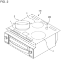
- Fig. 2 is a perspective view illustrating the main body and a power-receiver device of the inductive heating cooker according to Embodiment 1.
- an upper portion of a main body 100 of the inductive heating cooker includes a top plate 4 on which a heating target 5 such as a pot is placed.
- a power-receiver device 200 to which the electric power is transmitted from the main body 100 is placed on the top plate 4 and is allowed to be detached from the top plate 4.
- the power-receiver device 200 includes a temperature sensor configured to detect a temperature of the heating target 5. The details will be described later.
- the top plate 4 of the main body 100 includes a first heating area 1, a second heating area 2, and a third heating area 3 as heating areas for inductively heating the heating target 5.
- a first heating unit 11, a second heating unit 12, and a third heating unit 13 are provided to correspond to the respective heating areas.
- the main body 100 is configured to enable inductive heating of the heating target 5 placed on one of the heating areas.
- the first heating unit 11 and the second heating unit 12 are provided to be laterally aligned close to the front of the main body 100, and the third heating unit 13 is provided substantially at the center of the main body 100 close to the rear of the main body 100.
- the arrangement of the heating areas is not limited to the one described above.
- the three heating areas may be arranged to be aligned laterally in a substantially linear manner.
- the first heating unit 11 and the second heating unit 12 may be provided in such a manner that the respective centers of the first heating unit 11 and the second heating unit 12 are different in position in the depth direction.
- the number of heating areas is not limited to three, and may be one or two, or four or more.
- top plate 4 is made of an infrared transmitting material such as heat-resistant reinforced glass, crystallized glass, and borosilicate glass.
- the top plate 4 is fixed to an outer circumference of an upper opening of the main body 100 by use of a rubber packing or sealing material interposed between the top plate 4 and the main body 100 in such a manner that the outer circumference of the upper opening of the main body 100 is impermeable to water.
- circular pot position marks roughly indicating pot placement positions are formed by painting or printing, for example, corresponding to respective heating ranges (the heating areas) of the first heating unit 11, the second heating unit 12, and the third heating unit 13.
- An operation unit 40a, an operation unit 40b, and an operation unit 40c (hereinafter occasionally collectively referred to as the operation units 40) are provided close to the front of the top plate 4 as input devices each for setting heating power to be input (electric power to be input) and a cooking menu (such as boiling mode and frying mode) when the heating target 5 is heated by the corresponding one of the first heating unit 11, the second heating unit 12, and the third heating unit 13. Furthermore, a display unit 41a, a display unit 41b, and a display unit 41c (hereinafter occasionally collectively referred to as the display units 41) for displaying information such as the operating state of the main body 100 and details of inputs and operations sent from the operation units 40 are provided close to the operation units 40.
- the configurations of the operation units 40a to 40c and the display units 41a to 41c are not limited to particular configurations.
- the operation units 40a to 40c and the display units 41a to 41c may be provided for the respective heating areas, or an operation unit 40 and a display unit 41 may be provided for the heating areas as a whole.
- the operation units 40a to 40c are made of mechanical switches, such as push switches and tactile switches, or touch switches that detect an input operation through a change in capacitance of an electrode, for example.
- the display units 41a to 41c are made of liquid crystal devices (LCDs) or LEDs, for example.
- the display-and-operation unit 43 is made of a touch panel having touch switches arranged on an upper surface of an LCD, for example.
- the main body 100 accommodates the first heating unit 11, the second heating unit 12, and the third heating unit 13, each of which is made of a heating coil.
- the first heating unit 11, the second heating unit 12, and the third heating unit 13 may be made of an electric heater configured to perform radiation heating, for example (a nichrome wire, a halogen heater, or a radiant heater, for example).
- the heating coil is formed by winding a conductive wire made of a given metal (copper or aluminum, for example) and coated with an insulating film. Each of the heating coils is supplied with a high-frequency power by drive circuits 50, and thereby generates a high-frequency magnetic field.
- the main body 100 of the inductive heating cooker accommodates the drive circuits 50 configured to supply the high-frequency power to the heating coils of the first heating unit 11, the second heating unit 12, and the third heating unit 13, and a control unit 45 configured to control the operation of the entire inductive heating cooker including the drive circuits 50.
- a power transmission coil 65 configured to transmit the electric power to the power-receiver device 200 by magnetic resonance is provided under the top plate 4 of the main body 100.
- the power transmission coil 65 is formed by winding a conductive wire made of a given metal (copper or aluminum, for example) and coated with an insulating film.
- the inductance of the power transmission coil 65 is smaller than that of the heating coil.
- the power transmission coil 65 is provided along an edge of the top plate 4, for example.
- the power transmission coil 65 is provided to surround the first heating unit 11, the second heating unit 12, and the third heating unit 13, in a plan view.
- a range can be increased in which one power transmission coil 65 is provided in an area of the top plate 4 in which the heating units are not provided.
- the shape and arrangement of the power transmission coil 65 are not limited to the ones described above.
- the power transmission coil 65 may be provided to surround one heating unit (heating coil) in a plan view.
- a plurality of power transmission coils 65 may be provided.
- Fig. 3 is a block diagram illustrating a configuration of the main body and the power-receiver device of the inductive heating cooker according to Embodiment 1.
- Fig. 3 illustrates a state in which the heating target 5 is placed on one of the heating areas on the top plate 4 of the main body 100 of the inductive heating cooker, and the power-receiver device 200 is placed on an area of the top plate 4 in which the heater areas are not provided.
- a non-contact power transmission system includes the main body 100 of the inductive heating cooker serving as a non-contact power transmission device, and the power-receiver device 200.
- the heating coil 11a, the display-and-operation unit 43, the control unit 45, a main-body communication device 47, the drive circuits 50, a power transmission circuit 60, and the power transmission coil 65 are provided in the main body 100 of the inductive heating cooker.
- the control unit 45 is made of a device such as a microcomputer and a digital signal processor (DSP). On the basis of information such as details of operations of the display-and-operation unit 43 and communication information received from the main-body communication device 47, the control unit 45 controls the drive circuits 50. The control unit 45 further displays information on the display-and-operation unit 43 depending on factors such as the operating state.
- DSP digital signal processor
- the main-body communication device 47 is made of a wireless communication interface conforming to a given communication standard, such as a wireless LAN, Bluetooth (registered trademark), infrared communication, and near field communication (NFC), for example.
- the main-body communication device 47 conducts wireless communication with a power-receiver communication device 85 of the power-receiver device 200.
- the power transmission circuit 60 supplies the electric power to the power transmission coil 65. The details will be described later.
- the power-receiver device 200 placed, for example, on the top plate 4 receives the electric power from the main body 100 in a non-contact manner.
- the power-receiver device 200 includes a power reception coil 80, a power reception circuit 81, a power-receiver control unit 83, the power-receiver communication device 85, and a temperature sensor 90 serving as a load circuit.
- the power reception coil 80 receives the electric power from the power transmission coil 65 through electromagnetic resonance.
- the power reception circuit 81 supplies the electric power received by the power reception coil 80 to a load. The details will be described later.
- the power-receiver control unit 83, the power-receiver communication device 85, and the temperature sensor 90 are operated by the electric power supplied from the power reception circuit 81.
- the temperature sensor 90 is made of an infrared ray sensor, for example, and detects the temperature of a side surface of the heating target 5 placed on the top plate 4 in a non-contact manner. Note that the temperature sensor 90 may be made of a contact type sensor such as a thermistor, for example. The temperature sensor 90 outputs a voltage signal corresponding to the detected temperature to the power-receiver control unit 83.
- the power-receiver control unit 83 is made of a device such as a microcomputer and a digital signal processor (DSP).
- the power-receiver control unit 83 causes the temperature sensor 90 to transmit the information on the temperature detected by the temperature sensor 90 to the power-receiver communication device 85.
- the power-receiver communication device 85 is made of a wireless communication interface conforming to the communication standard of the main-body communication device 47.
- the power-receiver communication device 85 conducts wireless communication with the main-body communication device 47.
- thermosensor 90 in Embodiment 1 corresponds to a "load circuit" in the present invention.
- the power-receiver communication device 85 corresponds to a "first communication device" in the present invention.
- the main-body communication device 47 corresponds to a "second communication device" in the present invention.
- Fig. 4 is a diagram illustrating one of the drive circuits of the inductive heating cooker according to Embodiment 1.
- the drive circuits 50 are provided for the respective heating units.
- the drive circuits 50 may have the same circuit configuration, or may have different circuit configurations for the respective heating units.
- Fig. 4 illustrates only one of the drive circuits 50.
- the drive circuit 50 includes a direct-current power supply circuit 22, an inverter circuit 23, and a resonant capacitor 24.
- An input current detecting unit 25 is made of a current sensor, for example.
- the input current detecting unit 25 detects a current to be input to the direct-current power supply circuit 22 from an alternating-current power supply (commercial power supply) 21, and outputs a voltage signal corresponding to the value of the input current to the control unit 45.
- the direct-current power supply circuit 22 includes a diode bridge 22a, a reactor 22b, and a smoothing capacitor 22c.
- the direct-current power supply circuit 22 converts an alternating-current voltage input to the direct-current power supply circuit 22 from the alternating-current power supply 21 into a direct-current voltage, and outputs the direct-current voltage to the inverter circuit 23.
- the inverter circuit 23 is an inverter known as a half-bridge inverter, in which IGBTs 23a and 23b serving as switching elements are each connected in series with the corresponding one of outputs of the direct-current power supply circuit 22.
- diodes 23c and 23d are connected in parallel with the IGBTs 23a and 23b, respectively, as flywheel diodes.
- the IGBTs 23a and 23b are driven on and off by a drive signal output from the control unit 45.
- the control unit 45 outputs the drive signal to alternately turn on and off the IGBTs 23a and 23b by placing the IGBT 23b in the off state when the IGBT 23a is turned on and placing the IGBT 23b in the on state when the IGBT 23a is turned off.
- the inverter circuit 23 thereby converts the direct-current power output from the direct-current power supply circuit 22 into alternating-current power having a specified frequency, and supplies the electric power to a resonant circuit made of the heating coil 11a and the resonant capacitor 24.
- the alternating-current power having a specified frequency is alternating-current power having a high frequency ranging from equal to or more than 20 kHz to less than 100 kHz.
- the resonant circuit With the resonant capacitor 24 connected in series with the heating coil 11a, the resonant circuit has a resonant frequency corresponding to factors such as the inductance of the heating coil 11a and the capacitance of the resonant capacitor 24.
- the inductance of the heating coil 11a changes depending on characteristics of the metal load, and the resonant frequency of the resonant circuit changes depending on the change in the inductance.
- a high-frequency current of approximately tens of amperes flows through the heating coil 11a, and the heating target 5 placed on a part of the top plate 4 immediately above the heating coil 11a is inductively heated by a high-frequency magnetic flux produced by the flowing high-frequency current.
- each of the IGBTs 23a and 23b serving as a switching element is made of a semiconductor made of a silicon-based material, for example, but may be made of a wideband gap semiconductor made of a material such as a silicon carbide-based material and a gallium nitride-based material.
- the use of the wideband gap semiconductor as the switching element enables power supply loss of the switching element to be reduced, and favorable heat transfer from the drive circuit 50 to be achieved even when the switching frequency (driving frequency) is increased to a high frequency (high speed). Consequently, it is possible to reduce the size of heat transfer fins of the drive circuit 50, and thus to reduce the size and cost of the drive circuit 50.
- a coil current detecting unit 26 is connected to the resonant circuit made of the heating coil 11a and the resonant capacitor 24.
- the coil current detecting unit 26 is made of a current sensor, for example.
- the coil current detecting unit 26 detects the current flowing through the heating coil 11a and outputs a voltage signal corresponding to the value of the coil current to the control unit 45.
- Fig. 4 illustrates the half-bridge drive circuit, but it is needless to say that a full-bridge drive circuit made of four IGBTs and four diodes may be used.
- Fig. 5 is a diagram illustrating a configuration of the main body and the power-receiver device of the inductive heating cooker according to Embodiment 1.
- Fig. 6 is a specific circuit diagram of a configuration of Fig. 5 .
- Fig. 5 and Fig. 6 each illustrate a configuration relating to power transmission using a magnetic resonance method, of the main body 100 and the power-receiver device 200 of the inductive heating cooker.
- the main body 100 and the power-receiver device 200 of the inductive heating cooker form a non-contact power transmission system adopting a magnetic resonance method (resonant coupling type) of performing power transmission using the resonance characteristics. More specifically, the main body 100 of the inductive heating cooker forms a resonance type power transmission device that transmits the electric power to the power-receiver device 200 by magnetic resonance.
- the power-receiver device 200 is a resonance type power-receiver device that receives the electric power from the main body 100 by magnetic resonance.
- the power transmission circuit 60 of the main body 100 includes a resonance type power supply 60a and a matching circuit 60b.
- the resonance type power supply 60a controls the supply of electric power to the power transmission coil 65, converts direct current or alternating current input power into an alternating current having a predetermined frequency, and outputs this alternating current.
- This resonance type power supply 60a is made of a power supply circuit having a resonance switching method, and has an output impedance Zo, a resonance frequency fo, and a resonance characteristic value Qo.
- the resonance frequency fo of the resonance type power supply 60a is set to a frequency in a MHz band.
- the resonance frequency fo is 6.78 MHz, for example. Note that the resonance frequency fo is not limited to 6.78 MHz, and may be a frequency that is an integral multiple of 6.78 MHz in the MHz band.
- the matching circuit 60b performs impedance matching the output impedance Zo of the resonance type power supply 60a, and the pass characteristic impedance Zt of the power transmission coil 65.
- This matching circuit 60b is made of a filter of ⁇ type or L type that includes inductors L and capacitors C, and has the pass characteristic impedance Zp of the filter.
- the power transmission coil 65 receives the alternating current power from the resonance type power supply 60a via the matching circuit 60b, and performs a resonance operation to generate a non-radiative electromagnetic field in the vicinity of the power transmission coil 65, thereby transmitting the electric power to the power reception coil 80 of the power-receiver device 200.
- This power transmission coil 65 forms a resonance circuit including a coil and a capacitor C5, and serves as a resonance type antenna.
- the power transmission coil 65 has the pass characteristic impedance Zt, a resonance frequency ft, and a resonance characteristic value Qt.
- the resonance frequency fo and the resonance characteristic value Qo of the resonance type power supply 60a are determined from the output impedance Zo of the resonance type power supply 60a and the pass characteristic impedance Zp of the matching circuit 60b.
- the resonance frequency ft and the resonance characteristic value Qt of the power transmission coil 65 are determined from the pass characteristic impedance Zt of the power transmission coil 65 and the pass characteristic impedance Zp of the matching circuit 60b.
- the main body 100 of the inductive heating cooker has a resonance characteristic value Qtx of the following mathematic formula (1) on the basis of these two resonance characteristic values Qo and Qt.
- Qtx ⁇ Qo ⁇ Qt
- the power reception circuit 81 of the power-receiver device 200 includes a rectifier circuit 81a, and a conversion circuit 81b.
- the power reception coil 80 receives the electric power by performing a resonant coupling operation of coupling with the non-radiative electromagnetic field from the power transmission coil 65, and outputs the alternating current power.
- This power reception coil 80 forms a resonance circuit including a coil and a capacitor C11, and serves as a resonance type antenna.
- the power reception coil 80 has the pass characteristic impedance Zr.
- the rectifier circuit 81a is a matching rectifier circuit having a rectifying function of converting the alternating current power from the power reception coil 80 into direct current power, and a matching function of performing impedance matching the pass characteristic impedance Zr of the power reception coil 80 and the input impedance ZRL of the conversion circuit 81b.
- the matching function is performed by a filter of ⁇ type or L type that includes inductors L and capacitors C.
- the rectifier circuit 81a also has a pass characteristic impedance Zs.
- the rectifier circuit 81a having the rectifying function and the matching function is shown above, the rectifier circuit 81a is not limited to the one shown above, and can include only the rectifying function even though its rectifying efficiency drops.
- the conversion circuit 81b receives the direct current power from the rectifier circuit 81a, and converts this direct current power into a predetermined voltage and supplies this predetermined voltage to a load circuit (temperature sensor 90 or other devices).
- This conversion circuit 81b is made of an LC filter (smoothing filter) for smoothing a high-frequency voltage ripple, a DC-DC converter for converting the direct current power into the direct current power having the predetermined voltage, and other devices, and has the input impedance ZRL of the conversion circuit 81b.
- the DC-DC converter can be eliminated, and the conversion circuit 81b can be made only of the smoothing filter.
- the resonance characteristic value Qr and the resonance frequency fr of the power-receiver device 200 are determined from the pass characteristic impedance Zr of the power reception coil 80, the pass characteristic impedance Zs of the rectifier circuit 81a, and the input impedance ZRL of the conversion circuit 81b.
- the resonance characteristic value of the main body 100 preferably falls within the range given by the following mathematic formula (3).
- the reduction in the power transmission efficiency can be decreased by providing a correlation among the three resonance characteristic values of the resonance characteristic value Qo of the resonance type power supply 60a, the resonance characteristic value Qt of the power transmission coil 65, and the resonance characteristic value Qr of the power-receiver device 200. Consequently, comparing the power transmission using the magnetic resonance method (resonant coupling type) with the power transmission using the electromagnetic induction method (electromagnetic induction coupling type), the distance between the power transmission coil 65 and the power reception coil 80 can be increased.
- a user places the heating target 5 such as a pot on one of the heating areas of the top plate 4 of the main body 100.
- the user also places the power-receiver device 200 on the top plate 4.
- the temperature sensor 90 of the power-receiver device 200 is a non-contact type sensor such as an infrared ray sensor, for example, the user places the power-receiver device 200 at a given position on the top plate 4.
- the temperature sensor 90 of the power-receiver device 200 is a contact type sensor such as a thermistor, for example, the user places the power-receiver device 200 on the top plate 4 in such a manner that the power-receiver device 200 contacts the side surface of the heating target 5.
- the distance in which the electric power can be transmitted is long, and consequently the power-receiver device 200 need not to be provided to face the power transmission coil 65.
- the user performs operation of starting heating (input heating power) with the display-and-operation unit 43.
- the control unit 45 controls the inverter circuit 23 depending on the set electric power (heating power).
- High-frequency drive signals with a frequency of, for example, approximately 20 kHz to 100 kHz are input to the IGBTs 23a and 23b of the inverter circuit 23 and the IGBTs 23a and 23b are turned on and off alternately, thereby supplying a high-frequency current to the resonance circuit made of the heating coil 11a and the resonant capacitor 24.
- the high-frequency current flows through the heating coil 11a, a high-frequency magnetic field is generated, eddy currents flow at a bottom of the heating target 5 in such a direction as to cancel off magnetic flux variations, and the heating target 5 is heated by losses due to the flowing eddy currents.
- the control unit 45 operates the power transmission circuit 60 and causes the power transmission circuit 60 to start supply of the electric power to the power transmission coil 65.
- the electric power is thereby supplied from the power transmission coil 65 to the power reception coil 80 of the power-receiver device 200 by magnetic resonance.
- the electric power received by the power reception coil 80 is supplied from the power reception circuit 81 to the power-receiver control unit 83, the power-receiver communication device 85, and the temperature sensor 90.
- the temperature sensor 90 of the power-receiver device 200 detects the temperature of the heating target 5.
- the power-receiver control unit 83 causes the temperature sensor 90 to transmit the information on the temperature detected by the temperature sensor 90 to the power-receiver communication device 85.
- the main-body communication device 47 of the main body 100 receives the information on the temperature transmitted from the power-receiver communication device 85, and outputs this information to the control unit 45.
- the control unit 45 of the main body 100 controls the driving of the drive circuits 50 depending on the information on the temperature acquired from the temperature sensor 90 of the power-receiver device 200.
- the main body 100 includes the top plate 4 on which the heating target 5 is placed, the heating coil 11a provided under the top plate 4 and configured to inductively heat the heating target 5, the drive circuit 50 configured to supply the electric power to the heating coil 11a, the power transmission coil 65 configured to transmit the electric power by magnetic resonance, and the power transmission circuit 60 configured to supply the electric power to the power transmission coil 65.
- the power-receiver device 200 includes the power reception coil 80 configured to receive the electric power from the power transmission coil 65 by the magnetic resonance, and the load circuit configured to operate by the electric power received by the power reception coil 80.
- the restriction on an installation position of the power-receiver device 200 can thus be more alleviated, the power-receiver device 200 receiving the electric power from the main body 100 of the inductive heating cooker.
- the electric power is transmitted to the power-receiver device 200 from the main body 100 of the inductive heating cooker by magnetic resonance, the electric power can be transmitted even when the power transmission coil 65 and the power reception coil 80 are not arranged to face each other. Consequently, it is possible to increase the degree of freedom in the installation position of the power-receiver device 200 to be placed on the top plate 4 and improve the usability.
- the electric power can be stably transmitted even when the power-receiver device 200 is placed anywhere on the top plate. Consequently, it is possible to obtain an inductive heating cooker having the increased degree of freedom in the installation position of the power-receiver device 200 and the improved usability.
- a plurality of power transmission coils 65 need not be provided at respective positions at which the power-receiver device 200 is placed, and thus to obtain an inexpensive inductive heating cooker.
- the resonance frequency of the power transmission by magnetic resonance is largely different from the frequency of the coil current flowing through the heating coil 11a to perform inductive heating
- the power transmission from the main body 100 to the power-receiver device 200 is not affected by the magnetic field generated by the coil current flowing through the heating coil 11a.
- the inductive heating of the heating target 5 and the power transmission to the power-receiver device 200 can be simultaneously performed.
- the frequency of the power transmission approximates the frequency of the coil current flowing through the heating coil 11a.
- the interference occurs between the magnetic field of the power transmission using the electromagnetic induction coupling and the magnetic field generated from the heating coil 11a, which may cause the malfunction. Consequently, in a case in which the electric power is transmitted using the electromagnetic induction coupling, it is difficult to simultaneously perform the inductive heating and the power transmission. Consequently, in a case in which the electric power is transmitted using the electromagnetic induction coupling, it is necessary to reduce the electric power to be input for the inductive heating or to temporarily stop the inductive heating.
- the electric power is transmitted by magnetic resonance, and consequently it is not necessary to reduce the electric power to be input for the inductive heating or to stop the inductive heating. Consequently, it is possible to obtain an inductive heating cooker with which food can be cooked in a short time and having the improved usability.
- the electric power is transmitted by magnetic resonance, and consequently the electric power can be stably transmitted even when the displacement occurs between the position of the power transmission coil 65 and the position of the power reception coil 80, that is, the power transmission coil 65 and the power reception coil 80 are not arranged to face each other.
- the power transmission coil 65 is provided to surround a plurality of heating units in a plan view.
- the power transmission coil 65 is provided under the top plate 4 and along the edge of the top plate 4.
- a range can be increased in which one power transmission coil 65 is provided in an area of the top plate 4 in which the heating units are not provided.
- the resonance frequency of the power transmission by magnetic resonance is largely different from the driving frequency of the heating coil 11a, the power transmission from the main body 100 to the power-receiver device 200 is not affected by the magnetic field generated by the coil current flowing through the heating coil 11a even when the power transmission coil 65 is provided to surround the heating coil 11a.
- the frequency of the coil current flowing through the heating coil approximates the frequency of the power transmission, and consequently the power transmission from the main body to the power-receiver device is more likely to be affected by the magnetic field generated by the coil current flowing through the heating coil. Consequently, in a case in which the electric power is transmitted using the electromagnetic induction coupling, it is necessary to provide the power transmission coil for the power transmission at a position at which the heating coil is not provided, thereby restricting the installation position of the power transmission coil.
- the electric power is transmitted by magnetic resonance, and consequently it is possible to alleviate restriction on an installation position of the power transmission coil 65.
- the resonance frequency of the magnetic resonance is a frequency in a MHz band.
- the driving frequency of the drive circuit 50 ranges from equal to or more than 20 kHz to less than 100 kHz, and the resonance frequency of the magnetic resonance is 6.78 MHz or a frequency that is an integral multiple of 6.78 MHz.
- the resonance frequency of the power transmission by magnetic resonance is largely different from the frequency of the coil current flowing through the heating coil 11a
- the power transmission from the main body 100 to the power-receiver device 200 is not affected by the magnetic field generated by the coil current flowing through the heating coil 11a. Consequently, the electric power can be stably transmitted regardless of the magnitude of the coil current, that is, the magnitude of the electric power to be input.
- the conductor (metal) placed on the top plate 4 is not inductively heated by the magnetic field generated from the power transmission coil 65. Even when the metal cooker, for example, is placed on the top plate 4, the metal cooker is not inductively heated by the magnetic field generated from the power transmission coil 65.
- the inductance of the power transmission coil 65 can be extremely smaller than that of the heating coil 11a. Consequently, it is not necessary to provide a magnetic material such as ferrite to the power transmission coil 65. Consequently, the size of the main body 100 can be reduced, thereby obtaining an inexpensive inductive heating cooker.
- the power-receiver device 200 includes the power-receiver communication device 85 configured to transmit the information on the temperature detected by the temperature sensor 90 configured to detect the temperature of the heating target 5.
- the main body 100 includes the main-body communication device 47 configured to receive the information on the temperature transmitted from the power-receiver communication device 85, and the control unit 45 configured to control the driving of the drive circuits 50 depending on the information on the temperature.
- the restriction on an installation position of the temperature sensor 90 configured to detect the temperature of the heating target 5 can be alleviated, thereby increasing the degree of freedom in the installation position of the temperature sensor 90 to be placed on the top plate 4. Consequently, the installation position of the temperature sensor 90 can be changed arbitrarily depending on, for example, the shape and size of the heating target 5. Consequently, the usability can be improved.
- the temperature sensor 90 is made of a contact type sensor such as a thermistor, for example, and the power-receiver device 200 is provided to contact the side surface of the heating target 5, the power transmission from the main body 100 to the power-receiver device 200 is not affected by the magnetic field generated by the coil current flowing through the heating coil 11a.
- the temperature of the side surface of the heating target 5 can be directly detected by directly attaching the temperature sensor 90 to the side surface of the heating target 5, and thus to obtain an inductive heating cooker with high temperature detection accuracy.
- the magnetic flux produced by the electromagnetic induction interlinks with the metal portion of the side surface of the heating target, thereby screening the magnetic field, so that the electric power cannot be transmitted.
- the electric power is transmitted by magnetic resonance, and consequently the power transmission is hardly affected by the metal portion of the heating target 5, which enables the power transmission.
- Fig. 7 is a perspective view illustrating Modified Example 1 of power-receiver devices of the inductive heating cooker according to Embodiment 1.
- a configuration provided with a plurality of power-receiver devices 200 may be employed.
- the plurality of power-receiver devices 200 each receive the electric power from one power transmission coil 65.
- the power-receiver control units 83 of the plurality of power-receiver devices 200 cause the respective temperature sensors 90 to transmit the information on the temperatures acquired from the respective temperature sensors 90 to the respective power-receiver communication devices 85.
- the control unit 45 of the main body 100 acquires the information on the temperature from each of the plurality of power-receiver devices 200, and controls driving of the drive circuits 50 using the information on a plurality of temperatures.
- the temperature sensors 90 of the plurality of the power-receiver devices 200 detect the temperature of one heating target 5.
- the control unit 45 calculates the average temperature, the maximum temperature, or the minimum temperature on the basis of the received information on the plurality of temperatures, and controls the driving of the drive circuits 50 on the basis of the calculated values.
- a plurality of power-receiver devices 200 may be provided for the respective heating areas.
- the power-receiver control units 83 of the plurality of power-receiver devices 200 cause the respective temperature sensors 90 to transmit the identification information indicating the heating areas in addition to the information on the temperatures acquired from the respective temperature sensors 90 to the respective power-receiver communication devices 85.
- the control unit 45 of the main body 100 acquires the information on the temperature from each of the plurality of power-receiver devices 200 together with the identification information.
- the control unit 45 acquires the temperatures of the heating targets 5 placed on the respective heating areas on the basis of the received information on the plurality of temperatures, and controls the driving of the drive circuits 50 of the respective heating units.
- providing the plurality of power-receiver devices 200 each having the temperature sensor 90 enables the accuracy in detection of the temperature to be enhanced and the temperature variation of the heating target 5 to be reduced, and thus to obtain an inductive heating cooker with excellent usability. Also in a case in which the plurality of heating targets 5 are simultaneously heated, the temperature of each of the heating targets 5 can be simultaneously detected, and thus an inductive heating cooker with excellent usability can be obtained.
- Fig. 8 is a schematic diagram illustrating Modified Example 2 of a power-receiver device of the inductive heating cooker according to Embodiment 1.
- a vibration sensor 90b may be provided as a load circuit of a power-receiver device 200.
- the power-receiver device 200 may be provided with the vibration sensor 90b instead of the above-described temperature sensor 90, or may be provided with the vibration sensor 90b in addition to the temperature sensor 90.
- the vibration sensor 90b is operated by the electric power supplied from the power reception circuit 81.
- the vibration sensor 90b detects the vibration from a measurement target.
- vibration sensor 90b corresponds to the "load circuit" in the present invention.
- the power-receiver device 200 is provided to contact the side surface of the heating target 5, so that the vibration sensor 90b detects the vibration of the heating target 5.
- the vibration sensor 90b detects the vibration of the heating target 5.
- the vibration sensor 90b outputs a voltage signal corresponding to the detected vibration to the power-receiver control unit 83.
- the power-receiver control unit 83 of the power-receiver device 200 causes the vibration sensor 90b to transmit the information on vibration acquired from the vibration sensor 90b to the power-receiver communication device 85.
- the control unit 45 of the main body 100 controls driving of the drive circuits 50 using the information on the vibration acquired from the power-receiver device 200.
- the control unit 45 determines that the water in the heating target 5 has boiled.
- the control unit 45 controls the input heating power in such a manner that the input heating power is reduced.
- the control unit 45 may issue a notification on the display-and-operation unit 43 that the water has boiled.
- providing the vibration sensor 90b enables the detection of boiling.
- the boiling state can be maintained even when the heating power to be input (electric power to be input) is reduced after boiling, and consequently the electric power to be input can be reduced.
- Reduction in the electric power to be input can decrease the wasteful consumption of electric power, and thus to obtain an inductive heating cooker that achieves electric power saving.
- Fig. 9 is a schematic diagram illustrating Modified Example 3 of a power-receiver device of the inductive heating cooker according to Embodiment 1.
- the power-receiver device 200 may be provided with a holding unit 210 configured to hold the power-receiver device 200 at the side surface of the heating target 5.
- the distance between the power transmission coil 65 and the power reception coil 80 can be increased.
- the electric power can be transmitted even when the power-receiver device 200 is provided above the top plate 4 (to be lifted up from the top plate), and thus to obtain an inductive heating cooker with excellent usability.
- Embodiment 2 a configuration provided with a display-and-operation unit 43 serving as a load circuit of the power-receiver device will be described below.
- Embodiment 1 Note that in the following description, the same parts as those of Embodiment 1 described above will be denoted by the same reference signs, and the differences from Embodiment 1 will be mainly described.
- Fig. 10 is an exploded perspective view illustrating a main body of an inductive heating cooker according to Embodiment 2.
- Fig. 11 is a perspective view illustrating the main body and a power-receiver device of the inductive heating cooker according to Embodiment 2.
- Fig. 12 is a block diagram illustrating a configuration of the main body and the power-receiver device of the inductive heating cooker according to Embodiment 2.
- a main body 101 of the inductive heating cooker according to Embodiment 2 does not include the operation unit 40, the display unit 41, and the display-and-operation unit 43 configured in such a manner that the operation unit 40 and the display unit 41 are integrated.
- the other configurations of the main body 101 are similar to those of the main body 100 of Embodiment 1 described above.
- a power-receiver device 201 of the inductive heating cooker according to Embodiment 2 includes the display-and-operation unit 43 serving as a load circuit.
- the display-and-operation unit 43 of the power-receiver device 201 is operated by the electric power supplied from the power reception circuit 81.
- the display-and-operation unit 43 is configured in such a manner that the operation unit 40 for receiving information on operation input to the main body 101 of the inductive heating cooker and the display unit 41 for displaying the information on the operation of the main body 101 are integrated.
- the other configurations of the power-receiver device 201 are similar to those of the power-receiver device 200 of Embodiment 1 described above.
- operation unit 40, the display unit 41, and the display-and-operation unit 43 in Embodiment 2 each correspond to the "load circuit" in the present invention.
- the power-receiver control unit 83 causes the display-and-operation unit 43 to transmit the information on the input operation received by the display-and-operation unit 43 to the power-receiver communication device 85.
- the information on this input operation is, for example, information on setting of heating power to be input (electric power to be input) and a cooking menu when the heating target 5 is heated.
- the control unit 45 of the main body 101 controls the driving of the drive circuits 50 depending on the information on the input operation received by the main-body communication device 47.
- the control unit 45 transmits the display information on the operation of the main body 101 to the main-body communication device 47.
- the power-receiver control unit 83 of the power-receiver device 201 causes the display-and-operation unit 43 to display the display information received by the power-receiver communication device 85.
- This display information is, for example, information on setting of heating power to be input (electric power to be input) and a cooking menu when the heating target 5 is heated and information on the operation state.
- the power-receiver device 201 includes the display-and-operation unit 43 configured in such a manner that the operation unit 40 for receiving information on operation input to the main body 101 of the inductive heating cooker and the display unit 41 for displaying the information on the operation of the main body 101 are integrated.
- the main body 101 does not include the operation unit 40, the display unit 41, and the display-and-operation unit 43 configured in such a manner that the operation unit 40 and the display unit 41 are integrated, thereby capable of simplifying the configuration of the main body 101 and achieving downsizing.
- the power-receiver device 201 includes the display-and-operation unit 43 configured in such a manner that the operation unit 40 and the display unit 41 are integrated has been described, but the present invention is not limited to the configuration described above. Only one of the operation unit 40 and the display unit 41 may be provided in the power-receiver device 201.
- Embodiment 2 the configuration in which the main body 101 does not include the operation unit 40, the display unit 41, and the display-and-operation unit 43 has been described, but the present invention is not limited to the configuration described above. Only one of the operation unit 40 and the display unit 41 may be provided in the main body 101. Both the operation unit 40 and the display unit 41 may be provided in each of the main body 101 and the power-receiver device 201. A part of the operation unit 40 and the display unit 41 may be provided.
- Fig. 13 is a perspective view illustrating Modified Example of a power-receiver device of the inductive heating cooker according to Embodiment 2.
- the main body 101 of the inductive heating cooker is installed in a kitchen 300 provided with, for example, a sink.
- a housing portion (not illustrated) to which the main body 101 of the inductive heating cooker is fitted is formed in the kitchen 300, and a flat-plate shaped workboard 301 is provided on a top surface of the kitchen 300.
- the top plate 4 of the inductive heating cooker is exposed from the workboard 301 in a state where the main body 101 of the inductive heating cooker is incorporated in the kitchen 300.
- the workboard 301 of the kitchen 300 is made of insulating (non-metallic) materials such as wood, synthetic resin (for example, an artificial marble), and a stone material, for example.
- the power-receiver device 201 having the display-and-operation unit 43 may be placed on the workboard 301 of the kitchen 300.
- the electric power is transmitted to the power-receiver device 201 from the main body 101 of the inductive heating cooker by magnetic resonance, the electric power can be transmitted even when the power transmission coil 65 and the power reception coil 80 are not arranged to face each other.
- the workboard 301 is made of insulating materials, the power transmission coil 65 is not screened from the power reception coil 80.
- the electric power can be transmitted from the main body 101 even when the power-receiver device 201 is placed on the workboard 301. Consequently, the operation and display of the display-and-operation unit 43 can be performed in a state where the power-receiver device 201 is placed on the workboard 301, thereby improving the usability of the inductive heating cooker.
- Embodiment 3 a configuration in which a heater is provided as a load circuit of the power-receiver device will be described below.
- Embodiment 1 Note that in the following description, the same parts as those of Embodiment 1 described above will be denoted by the same reference signs, and the differences from Embodiment 1 will be mainly described.
- Fig. 14 is a schematic diagram illustrating a configuration of an inductive heating cooker according to Embodiment 3.
- Fig. 14 schematically illustrates a longitudinal section of the main body 100 and the power-receiver device 202 viewed from the fronts of the main body 100 and the power-receiver device 202.
- the power-receiver device 202 of the inductive heating cooker according to Embodiment 3 includes an upper heater 91 serving as a load circuit.
- the upper heater 91 is connected to the power reception coil 80 via the power reception circuit 81 (not illustrated).
- the upper heater 91 is made of a heating element that generates heat by the electric power received by the power reception coil 80.
- a sheathed heater serving as a resistance heating element is employed as the upper heater 91.
- a specific configuration of the upper heater 91 is not limited to the one described above, and a given heating element such as a halogen heater and a far-infrared heater may be employed.
- the upper heater 91 is supported above the heating target 5 by a supporting unit 220.
- the supporting unit 220 is formed by a casing serving as an outer shell of the power-receiver device 202, for example.
- the supporting unit 220 is formed to extend upward from the bottom portion that houses the power reception coil 80 and then extend horizontally, thereby having an L-shaped cross section. More specifically, the supporting unit 220 supports the upper heater 91 so that the upper heater 91 is located above the heating coil 11a and the heating target 5 when the power-receiver device 202 is placed on the top plate 4.
- the distance between the top plate 4 and the upper heater 91 is set to be larger than the height of a pod or a frying pan considered as the heating target 5.
- the supporting unit 220 may be configured to move the upper heater 91 up and down.
- the upper heater 91 in Embodiment 3 corresponds to a "load circuit" in the present invention.
- the control unit 45 of the main body 100 operates the power transmission circuit 60 and causes the power transmission circuit 60 to start the supply of electric power to the power transmission coil 65.
- the electric power is thereby supplied to the power reception coil 80 of the power-receiver device 200 from the power transmission coil 65 by magnetic resonance.
- the electric power received by the power reception coil 80 is supplied to the upper heater 91 from the power reception circuit 81.
- the upper heater 91 thereby heats food 5b in the heating target 5 from above by thermal radiation. More specifically, the cooking by inductive heating and the cooking through non-contact power transmission can be simultaneously performed. Furthermore, the cooking by inductive heating and the cooking through non-contact power transmission are independently controllable. Consequently, it is possible to obtain an inductive heating cooker with which food can be nicely cooked in a short time. That is, with the drive circuits 50 and the power transmission circuit 60, it is possible to independently control inductive heating with the heat from the heating target 5 and upper heating by the upper heater 91, and thus to obtain an inductive heating cooker with which food can be nicely cooked in a short time.
- Embodiment 4 a configuration in which a stirring device is provided as a load circuit of the power-receiver device will be described below.
- Embodiment 1 Note that in the following description, the same parts as those of Embodiment 1 described above will be denoted by the same reference signs, and the differences from Embodiment 1 will be mainly described.
- Fig. 15 is a schematic diagram illustrating a configuration of an inductive heating cooker according to Embodiment 4.
- Fig. 15 schematically illustrates a longitudinal section of the main body 100 and a power-receiver device 203 viewed from of the fronts of the main body 100 and the power-receiver device 203.
- the power-receiver device 203 of the inductive heating cooker according to Embodiment 4 includes a stirring device 92 serving as a load circuit.
- the stirring device 92 includes a motor 92a, a shaft 92b, and a blade unit 92c.
- the stirring device 92 is supported above the heating target 5 by the supporting unit 220.
- the heating target 5 such as a pot and a frying pan, containing the food 5b, such as stew and fried food, for example, is placed on one of the heating areas of the top plate 4, the blade unit 92c of the stirring device 92 is placed in the heating target 5.
- the motor 92a is provided to an upper portion of the casing of the power-receiver device 203, for example, and is driven for rotation by the electric power received by the power reception coil 80.
- the shaft 92b has a rotary shaft disposed in the vertical direction, and has one end connected to the motor 92a to transmit drive force of the motor 92a.
- the blade unit 92c is attached to the shaft 92b, and stirs the food 5b with the shaft 92b driven for rotation.
- stirring device 92 in Embodiment 4 corresponds to a "load circuit" in the present invention.
- the control unit 45 of the main body 100 operates the power transmission circuit 60 and causes the power transmission circuit 60 to start the supply of electric power to the power transmission coil 65.
- the electric power is thereby supplied to the power reception coil 80 of the power-receiver device 200 from the power transmission coil 65 by magnetic resonance.
- the electric power received by the power reception coil 80 is supplied to the stirring device 92 from the power reception circuit 81.
- the cooking by induction heating and cooking by stirring through non-contact power transmission can thus be simultaneously performed. Furthermore, the cooking by induction heating and the cooking by stirring through non-contact power transmission are independently controllable. Consequently, it is possible to obtain an inductive heating cooker with which food can be nicely cooked in a short time.
- Embodiments 1 to 4 described above a configuration in which the power-receiver device has one type of load circuit has been described, but a plurality of load circuits of Embodiments 1 to 4 may be used in combination. That is, a plurality of power-receiver devices are provided, and at least one of the plurality of power-receiver devices may have a load circuit different from the load circuit each in other ones of the plurality of power-receiver devices.
- the load circuit of the power-receiver device is not limited to the examples of Embodiments 1 to 4 described above, and may be a cooking device (a fryer, a steamer, a roaster, a toaster, and other devices) used for cooking the food, for example.
- the load circuit of the power-receiver device may be the cooking device (a blender, a mixer, a mill, a beater, a food processor, and other devices) used for preparing and precooking the food, for example.
- the load circuit of the power-receiver device may be a component detection sensor for detecting components (for example, salinity, sugar content, and other components), the component detection sensor being disposed in the heating target 5.
- Fig. 16 is a diagram illustrating a top plate and a power transmission coil of an inductive heating cooker according to Embodiment 5.
- Fig. 16(a) is a plan view of the top plate 4 when the top plate 4 is seen from the back
- Fig. 16(b) is a side view of the top plate 4.
- the power transmission coil 65 may be provided on the back surface (bottom surface) of the top plate 4.
- the power transmission coil 65 may be provided on the back surface of the top plate 4 by printed wiring.
- the main body 100 can be miniaturized.
- the assembling process of the main body 100 can be facilitated, and thus to obtain an inexpensive inductive heating cooker.
Landscapes
- Engineering & Computer Science (AREA)
- Computer Networks & Wireless Communication (AREA)
- Power Engineering (AREA)
- Physics & Mathematics (AREA)
- Electromagnetism (AREA)
- Induction Heating Cooking Devices (AREA)
Description
- The present invention relates to an inductive heating cooker that performs non-contact power transmission using a magnetic resonance method.
- An inductive heating cooker has been proposed in which a temperature detection unit is provided to a top plate. The inductive heating cooker includes a first coil provided at a bottom surface of the top plate, and a second coil provided in the temperature detection unit. When the second coil is provided to face the first coil, the first coil is coupled to the second coil by electromagnetic inductive coupling. Thus, the electric power is supplied from the first coil to the second coil.
Patent Literature 2 discloses an inductive heating cooker in which a heating coil is provided under a top plate and a power transmission coil is provided surrounding the heating coil.
Patent Literature 3 discloses an inductive heating cooker in which a plurality of heating coils are provided in a concentric manner. -
- Patent Literature 1:
JP 2010-049959 A - Patent Literature 2:
JP 3 363139 B2 - Patent Literature 3:
JP 5 992131 B1 - In the existing inductive heating cooker, the electric power is supplied by the electromagnetic inductive coupling. Thus, a power reception coil (second coil) provided in a power-receiver device (temperature detection unit) needs to face a power transmission coil (first coil) for supplying the electric power, which results in restriction on the installation position of the power-receiver device.
- The present invention has been made to solve the above-described problem, and an object of the present invention is to obtain an inductive heating cooker in which the electric power is transmitted from a main body to a power-receiver device, the inductive heating cooker being capable of alleviating restriction on an installation position of the power-receiver device.
- This problem is solved by an inductive heating cooker according to
claim 1. In particular, an inductive heating cooker of an embodiment of the present invention includes a main body and a power-receiver device. The main body includes a top plate on which a heating target is placed, a heating coil provided under the top plate and configured to inductively heat the heating target, a drive circuit configured to supply electric power to the heating coil, a power transmission coil configured to transmit the electric power by magnetic resonance, and a power transmission circuit configured to supply the electric power to the power transmission coil. The power-receiver device includes a power reception coil configured to receive the electric power from the power transmission coil by the magnetic resonance, and a load circuit configured to operate by the electric power received by the power reception coil. - An inductive heating cooker of an embodiment of the present invention includes a main body having a power transmission coil configured to transmit the electric power by magnetic resonance, and a power-receiver device having a power reception coil configured to receive the electric power from the power transmission coil by the magnetic resonance. Consequently, the restriction on an installation position of the power-receiver device can be alleviated.
-
- [
Fig. 1] Fig. 1 is an exploded perspective view illustrating a main body of an inductive heating cooker according toEmbodiment 1. - [
Fig. 2] Fig. 2 is a perspective view illustrating the main body and a power-receiver device of the inductive heating cooker according toEmbodiment 1. - [
Fig. 3] Fig. 3 is a block diagram illustrating a configuration of the main body and the power-receiver device of the inductive heating cooker according toEmbodiment 1. - [
Fig. 4] Fig. 4 is a diagram illustrating one of drive circuits of the inductive heating cooker according toEmbodiment 1. - [
Fig. 5] Fig. 5 is a diagram illustrating a configuration of the main body and the power-receiver device of the inductive heating cooker according toEmbodiment 1. - [
Fig. 6] Fig. 6 is a specific circuit diagram of a configuration ofFig. 5 . - [
Fig. 7] Fig. 7 is a perspective view illustrating Modified Example 1 of power power-receiver devices of the inductive heating cooker according toEmbodiment 1. - [
Fig. 8] Fig. 8 is a schematic diagram illustrating Modified Example 2 of a power-receiver device of the inductive heating cooker according toEmbodiment 1. - [
Fig. 9] Fig. 9 is a schematic diagram illustrating Modified Example 3 of a power-receiver device of the inductive heating cooker according toEmbodiment 1. - [
Fig. 10] Fig. 10 is an exploded perspective view illustrating a main body of an inductive heating cooker according toEmbodiment 2. - [
Fig. 11] Fig. 11 is a perspective view illustrating the main body and a power-receiver device of the inductive heating cooker according toEmbodiment 2. - [
Fig. 12] Fig. 12 is a block diagram illustrating a configuration of the main body and the power-receiver device of the inductive heating cooker according toEmbodiment 2. - [
Fig. 13] Fig. 13 is a perspective view illustrating Modified Example of a power-receiver device of the inductive heating cooker according toEmbodiment 2. - [
Fig. 14] Fig. 14 is a schematic diagram illustrating a configuration of an inductive heating cooker according toEmbodiment 3. - [
Fig. 15] Fig. 15 is a schematic diagram illustrating a configuration of an inductive heating cooker according toEmbodiment 4. - [
Fig. 16] Fig. 16 is a diagram illustrating a top plate and a power transmission coil of an inductive heating cooker according toEmbodiment 5. -
Fig. 1 is an exploded perspective view illustrating a main body of an inductive heating cooker according toEmbodiment 1. -
Fig. 2 is a perspective view illustrating the main body and a power-receiver device of the inductive heating cooker according toEmbodiment 1. - As illustrated in
Fig. 1 andFig. 2 , an upper portion of amain body 100 of the inductive heating cooker includes atop plate 4 on which aheating target 5 such as a pot is placed. A power-receiver device 200 to which the electric power is transmitted from themain body 100 is placed on thetop plate 4 and is allowed to be detached from thetop plate 4. In the inductive heating cooker according toEmbodiment 1, the power-receiver device 200 includes a temperature sensor configured to detect a temperature of theheating target 5. The details will be described later. - The
top plate 4 of themain body 100 includes afirst heating area 1, asecond heating area 2, and athird heating area 3 as heating areas for inductively heating theheating target 5. Afirst heating unit 11, asecond heating unit 12, and athird heating unit 13 are provided to correspond to the respective heating areas. Themain body 100 is configured to enable inductive heating of theheating target 5 placed on one of the heating areas. - In
Embodiment 1, thefirst heating unit 11 and thesecond heating unit 12 are provided to be laterally aligned close to the front of themain body 100, and thethird heating unit 13 is provided substantially at the center of themain body 100 close to the rear of themain body 100. Note that the arrangement of the heating areas is not limited to the one described above. For example, the three heating areas may be arranged to be aligned laterally in a substantially linear manner. Furthermore, thefirst heating unit 11 and thesecond heating unit 12 may be provided in such a manner that the respective centers of thefirst heating unit 11 and thesecond heating unit 12 are different in position in the depth direction. The number of heating areas is not limited to three, and may be one or two, or four or more. - The whole of
top plate 4 is made of an infrared transmitting material such as heat-resistant reinforced glass, crystallized glass, and borosilicate glass. Thetop plate 4 is fixed to an outer circumference of an upper opening of themain body 100 by use of a rubber packing or sealing material interposed between thetop plate 4 and themain body 100 in such a manner that the outer circumference of the upper opening of themain body 100 is impermeable to water. On thetop plate 4, circular pot position marks roughly indicating pot placement positions are formed by painting or printing, for example, corresponding to respective heating ranges (the heating areas) of thefirst heating unit 11, thesecond heating unit 12, and thethird heating unit 13. - An
operation unit 40a, anoperation unit 40b, and anoperation unit 40c (hereinafter occasionally collectively referred to as the operation units 40) are provided close to the front of thetop plate 4 as input devices each for setting heating power to be input (electric power to be input) and a cooking menu (such as boiling mode and frying mode) when theheating target 5 is heated by the corresponding one of thefirst heating unit 11, thesecond heating unit 12, and thethird heating unit 13. Furthermore, adisplay unit 41a, adisplay unit 41b, and adisplay unit 41c (hereinafter occasionally collectively referred to as the display units 41) for displaying information such as the operating state of themain body 100 and details of inputs and operations sent from the operation units 40 are provided close to the operation units 40. - Note that the configurations of the
operation units 40a to 40c and thedisplay units 41a to 41c are not limited to particular configurations. For example, theoperation units 40a to 40c and thedisplay units 41a to 41c may be provided for the respective heating areas, or an operation unit 40 and a display unit 41 may be provided for the heating areas as a whole. Note that theoperation units 40a to 40c are made of mechanical switches, such as push switches and tactile switches, or touch switches that detect an input operation through a change in capacitance of an electrode, for example. Furthermore, thedisplay units 41a to 41c are made of liquid crystal devices (LCDs) or LEDs, for example. - Note that the following description will be given of a case in which a display-and-
operation unit 43 configured in such a manner that the operation units 40 and the display units 41 are integrated is provided. The display-and-operation unit 43 is made of a touch panel having touch switches arranged on an upper surface of an LCD, for example. - Under the
top plate 4, themain body 100 accommodates thefirst heating unit 11, thesecond heating unit 12, and thethird heating unit 13, each of which is made of a heating coil. Note that at least one of thefirst heating unit 11, thesecond heating unit 12, and thethird heating unit 13 may be made of an electric heater configured to perform radiation heating, for example (a nichrome wire, a halogen heater, or a radiant heater, for example). - The heating coil is formed by winding a conductive wire made of a given metal (copper or aluminum, for example) and coated with an insulating film. Each of the heating coils is supplied with a high-frequency power by
drive circuits 50, and thereby generates a high-frequency magnetic field. - The
main body 100 of the inductive heating cooker accommodates thedrive circuits 50 configured to supply the high-frequency power to the heating coils of thefirst heating unit 11, thesecond heating unit 12, and thethird heating unit 13, and acontrol unit 45 configured to control the operation of the entire inductive heating cooker including thedrive circuits 50. - A
power transmission coil 65 configured to transmit the electric power to the power-receiver device 200 by magnetic resonance is provided under thetop plate 4 of themain body 100. Thepower transmission coil 65 is formed by winding a conductive wire made of a given metal (copper or aluminum, for example) and coated with an insulating film. The inductance of thepower transmission coil 65 is smaller than that of the heating coil. - As illustrated in
Fig. 1 , thepower transmission coil 65 is provided along an edge of thetop plate 4, for example. Thepower transmission coil 65 is provided to surround thefirst heating unit 11, thesecond heating unit 12, and thethird heating unit 13, in a plan view. Thus, a range can be increased in which onepower transmission coil 65 is provided in an area of thetop plate 4 in which the heating units are not provided. - Note that the shape and arrangement of the
power transmission coil 65 are not limited to the ones described above. For example, thepower transmission coil 65 may be provided to surround one heating unit (heating coil) in a plan view. Furthermore, a plurality of power transmission coils 65 may be provided. -
Fig. 3 is a block diagram illustrating a configuration of the main body and the power-receiver device of the inductive heating cooker according toEmbodiment 1. -
Fig. 3 illustrates a state in which theheating target 5 is placed on one of the heating areas on thetop plate 4 of themain body 100 of the inductive heating cooker, and the power-receiver device 200 is placed on an area of thetop plate 4 in which the heater areas are not provided. - A non-contact power transmission system includes the
main body 100 of the inductive heating cooker serving as a non-contact power transmission device, and the power-receiver device 200. - As illustrated in
Fig. 3 , theheating coil 11a, the display-and-operation unit 43, thecontrol unit 45, a main-body communication device 47, thedrive circuits 50, apower transmission circuit 60, and thepower transmission coil 65 are provided in themain body 100 of the inductive heating cooker. - The
control unit 45 is made of a device such as a microcomputer and a digital signal processor (DSP). On the basis of information such as details of operations of the display-and-operation unit 43 and communication information received from the main-body communication device 47, thecontrol unit 45 controls thedrive circuits 50. Thecontrol unit 45 further displays information on the display-and-operation unit 43 depending on factors such as the operating state. - The main-
body communication device 47 is made of a wireless communication interface conforming to a given communication standard, such as a wireless LAN, Bluetooth (registered trademark), infrared communication, and near field communication (NFC), for example. The main-body communication device 47 conducts wireless communication with a power-receiver communication device 85 of the power-receiver device 200. - The
power transmission circuit 60 supplies the electric power to thepower transmission coil 65. The details will be described later. - The power-
receiver device 200 placed, for example, on thetop plate 4 receives the electric power from themain body 100 in a non-contact manner. The power-receiver device 200 includes apower reception coil 80, apower reception circuit 81, a power-receiver control unit 83, the power-receiver communication device 85, and atemperature sensor 90 serving as a load circuit. - The
power reception coil 80 receives the electric power from thepower transmission coil 65 through electromagnetic resonance. Thepower reception circuit 81 supplies the electric power received by thepower reception coil 80 to a load. The details will be described later. - The power-
receiver control unit 83, the power-receiver communication device 85, and thetemperature sensor 90 are operated by the electric power supplied from thepower reception circuit 81. - The
temperature sensor 90 is made of an infrared ray sensor, for example, and detects the temperature of a side surface of theheating target 5 placed on thetop plate 4 in a non-contact manner. Note that thetemperature sensor 90 may be made of a contact type sensor such as a thermistor, for example. Thetemperature sensor 90 outputs a voltage signal corresponding to the detected temperature to the power-receiver control unit 83. - The power-
receiver control unit 83 is made of a device such as a microcomputer and a digital signal processor (DSP). The power-receiver control unit 83 causes thetemperature sensor 90 to transmit the information on the temperature detected by thetemperature sensor 90 to the power-receiver communication device 85. - The power-
receiver communication device 85 is made of a wireless communication interface conforming to the communication standard of the main-body communication device 47. The power-receiver communication device 85 conducts wireless communication with the main-body communication device 47. - Note that the
temperature sensor 90 inEmbodiment 1 corresponds to a "load circuit" in the present invention. - The power-
receiver communication device 85 corresponds to a "first communication device" in the present invention. - The main-
body communication device 47 corresponds to a "second communication device" in the present invention. -
Fig. 4 is a diagram illustrating one of the drive circuits of the inductive heating cooker according toEmbodiment 1. - Note that the
drive circuits 50 are provided for the respective heating units. Thedrive circuits 50 may have the same circuit configuration, or may have different circuit configurations for the respective heating units.Fig. 4 illustrates only one of thedrive circuits 50. As illustrated inFig. 4 , thedrive circuit 50 includes a direct-currentpower supply circuit 22, aninverter circuit 23, and aresonant capacitor 24. - An input current detecting
unit 25 is made of a current sensor, for example. The input current detectingunit 25 detects a current to be input to the direct-currentpower supply circuit 22 from an alternating-current power supply (commercial power supply) 21, and outputs a voltage signal corresponding to the value of the input current to thecontrol unit 45. - The direct-current
power supply circuit 22 includes adiode bridge 22a, areactor 22b, and a smoothingcapacitor 22c. The direct-currentpower supply circuit 22 converts an alternating-current voltage input to the direct-currentpower supply circuit 22 from the alternating-current power supply 21 into a direct-current voltage, and outputs the direct-current voltage to theinverter circuit 23. - The
inverter circuit 23 is an inverter known as a half-bridge inverter, in whichIGBTs power supply circuit 22. In theinverter circuit 23,diodes IGBTs IGBTs control unit 45. Thecontrol unit 45 outputs the drive signal to alternately turn on and off theIGBTs IGBT 23b in the off state when theIGBT 23a is turned on and placing theIGBT 23b in the on state when theIGBT 23a is turned off. Theinverter circuit 23 thereby converts the direct-current power output from the direct-currentpower supply circuit 22 into alternating-current power having a specified frequency, and supplies the electric power to a resonant circuit made of theheating coil 11a and theresonant capacitor 24. Note that the alternating-current power having a specified frequency is alternating-current power having a high frequency ranging from equal to or more than 20 kHz to less than 100 kHz. - With the
resonant capacitor 24 connected in series with theheating coil 11a, the resonant circuit has a resonant frequency corresponding to factors such as the inductance of theheating coil 11a and the capacitance of theresonant capacitor 24. When magnetic coupling with the heating target 5 (a metal load) is made, the inductance of theheating coil 11a changes depending on characteristics of the metal load, and the resonant frequency of the resonant circuit changes depending on the change in the inductance. - With the
drive circuit 50 configured in this manner, a high-frequency current of approximately tens of amperes flows through theheating coil 11a, and theheating target 5 placed on a part of thetop plate 4 immediately above theheating coil 11a is inductively heated by a high-frequency magnetic flux produced by the flowing high-frequency current. - Note that each of the
IGBTs drive circuit 50 to be achieved even when the switching frequency (driving frequency) is increased to a high frequency (high speed). Consequently, it is possible to reduce the size of heat transfer fins of thedrive circuit 50, and thus to reduce the size and cost of thedrive circuit 50. - A coil
current detecting unit 26 is connected to the resonant circuit made of theheating coil 11a and theresonant capacitor 24. The coilcurrent detecting unit 26 is made of a current sensor, for example. The coilcurrent detecting unit 26 detects the current flowing through theheating coil 11a and outputs a voltage signal corresponding to the value of the coil current to thecontrol unit 45. - Note that
Fig. 4 illustrates the half-bridge drive circuit, but it is needless to say that a full-bridge drive circuit made of four IGBTs and four diodes may be used. -
Fig. 5 is a diagram illustrating a configuration of the main body and the power-receiver device of the inductive heating cooker according toEmbodiment 1.Fig. 6 is a specific circuit diagram of a configuration ofFig. 5 . - Note that
Fig. 5 and Fig. 6 each illustrate a configuration relating to power transmission using a magnetic resonance method, of themain body 100 and the power-receiver device 200 of the inductive heating cooker. - The
main body 100 and the power-receiver device 200 of the inductive heating cooker form a non-contact power transmission system adopting a magnetic resonance method (resonant coupling type) of performing power transmission using the resonance characteristics. More specifically, themain body 100 of the inductive heating cooker forms a resonance type power transmission device that transmits the electric power to the power-receiver device 200 by magnetic resonance. The power-receiver device 200 is a resonance type power-receiver device that receives the electric power from themain body 100 by magnetic resonance. - As illustrated in
Fig. 5 and Fig. 6 , thepower transmission circuit 60 of themain body 100 includes a resonancetype power supply 60a and amatching circuit 60b. - The resonance
type power supply 60a controls the supply of electric power to thepower transmission coil 65, converts direct current or alternating current input power into an alternating current having a predetermined frequency, and outputs this alternating current. This resonancetype power supply 60a is made of a power supply circuit having a resonance switching method, and has an output impedance Zo, a resonance frequency fo, and a resonance characteristic value Qo. - The resonance frequency fo of the resonance
type power supply 60a is set to a frequency in a MHz band. - The resonance frequency fo is 6.78 MHz, for example. Note that the resonance frequency fo is not limited to 6.78 MHz, and may be a frequency that is an integral multiple of 6.78 MHz in the MHz band.
- The
matching circuit 60b performs impedance matching the output impedance Zo of the resonancetype power supply 60a, and the pass characteristic impedance Zt of thepower transmission coil 65. Thismatching circuit 60b is made of a filter of π type or L type that includes inductors L and capacitors C, and has the pass characteristic impedance Zp of the filter. - The
power transmission coil 65 receives the alternating current power from the resonancetype power supply 60a via thematching circuit 60b, and performs a resonance operation to generate a non-radiative electromagnetic field in the vicinity of thepower transmission coil 65, thereby transmitting the electric power to thepower reception coil 80 of the power-receiver device 200. Thispower transmission coil 65 forms a resonance circuit including a coil and a capacitor C5, and serves as a resonance type antenna. Thepower transmission coil 65 has the pass characteristic impedance Zt, a resonance frequency ft, and a resonance characteristic value Qt. - Furthermore, the resonance frequency fo and the resonance characteristic value Qo of the resonance
type power supply 60a are determined from the output impedance Zo of the resonancetype power supply 60a and the pass characteristic impedance Zp of thematching circuit 60b. The resonance frequency ft and the resonance characteristic value Qt of thepower transmission coil 65 are determined from the pass characteristic impedance Zt of thepower transmission coil 65 and the pass characteristic impedance Zp of thematching circuit 60b. - It is then seen that the
main body 100 of the inductive heating cooker has a resonance characteristic value Qtx of the following mathematic formula (1) on the basis of these two resonance characteristic values Qo and Qt.
[Math. 1]
- The
power reception circuit 81 of the power-receiver device 200 includes arectifier circuit 81a, and aconversion circuit 81b. - The
power reception coil 80 receives the electric power by performing a resonant coupling operation of coupling with the non-radiative electromagnetic field from thepower transmission coil 65, and outputs the alternating current power. Thispower reception coil 80 forms a resonance circuit including a coil and a capacitor C11, and serves as a resonance type antenna. Thepower reception coil 80 has the pass characteristic impedance Zr. - The
rectifier circuit 81a is a matching rectifier circuit having a rectifying function of converting the alternating current power from thepower reception coil 80 into direct current power, and a matching function of performing impedance matching the pass characteristic impedance Zr of thepower reception coil 80 and the input impedance ZRL of theconversion circuit 81b. The matching function is performed by a filter of π type or L type that includes inductors L and capacitors C. Therectifier circuit 81a also has a pass characteristic impedance Zs. Although therectifier circuit 81a having the rectifying function and the matching function is shown above, therectifier circuit 81a is not limited to the one shown above, and can include only the rectifying function even though its rectifying efficiency drops. - The
conversion circuit 81b receives the direct current power from therectifier circuit 81a, and converts this direct current power into a predetermined voltage and supplies this predetermined voltage to a load circuit (temperature sensor 90 or other devices). Thisconversion circuit 81b is made of an LC filter (smoothing filter) for smoothing a high-frequency voltage ripple, a DC-DC converter for converting the direct current power into the direct current power having the predetermined voltage, and other devices, and has the input impedance ZRL of theconversion circuit 81b. As an alternative, the DC-DC converter can be eliminated, and theconversion circuit 81b can be made only of the smoothing filter. - Furthermore, the resonance characteristic value Qr and the resonance frequency fr of the power-
receiver device 200 are determined from the pass characteristic impedance Zr of thepower reception coil 80, the pass characteristic impedance Zs of therectifier circuit 81a, and the input impedance ZRL of theconversion circuit 81b. - Then, the characteristic impedance of each of the functional units is set in such a manner that there is provided a correlation among the resonance characteristic value Qo of the resonance
type power supply 60a, the resonance characteristic value Qt of thepower transmission coil 65, and the resonance characteristic value Qr of the power-receiver device 200. More specifically, the resonance characteristic value Qtx (= √(Qo·Qt)) of themain body 100 is made to approximate the resonance characteristic value Qr of the power-receiver device 200 (the following mathematic formula (2)). - More specifically, the resonance characteristic value of the
main body 100 preferably falls within the range given by the following mathematic formula (3).
[Math. 2]
[Math. 3]
- Thus, the reduction in the power transmission efficiency can be decreased by providing a correlation among the three resonance characteristic values of the resonance characteristic value Qo of the resonance
type power supply 60a, the resonance characteristic value Qt of thepower transmission coil 65, and the resonance characteristic value Qr of the power-receiver device 200. Consequently, comparing the power transmission using the magnetic resonance method (resonant coupling type) with the power transmission using the electromagnetic induction method (electromagnetic induction coupling type), the distance between thepower transmission coil 65 and thepower reception coil 80 can be increased. - An operation of the inductive heating cooker of
Embodiment 1 will be described below. - A user places the
heating target 5 such as a pot on one of the heating areas of thetop plate 4 of themain body 100. - The user also places the power-
receiver device 200 on thetop plate 4. When thetemperature sensor 90 of the power-receiver device 200 is a non-contact type sensor such as an infrared ray sensor, for example, the user places the power-receiver device 200 at a given position on thetop plate 4. When thetemperature sensor 90 of the power-receiver device 200 is a contact type sensor such as a thermistor, for example, the user places the power-receiver device 200 on thetop plate 4 in such a manner that the power-receiver device 200 contacts the side surface of theheating target 5. As described above, in the power transmission using the magnetic resonance method (resonant coupling type), the distance in which the electric power can be transmitted is long, and consequently the power-receiver device 200 need not to be provided to face thepower transmission coil 65. - The user performs operation of starting heating (input heating power) with the display-and-
operation unit 43. - The
control unit 45 controls theinverter circuit 23 depending on the set electric power (heating power). High-frequency drive signals with a frequency of, for example, approximately 20 kHz to 100 kHz are input to theIGBTs inverter circuit 23 and theIGBTs heating coil 11a and theresonant capacitor 24. When the high-frequency current flows through theheating coil 11a, a high-frequency magnetic field is generated, eddy currents flow at a bottom of theheating target 5 in such a direction as to cancel off magnetic flux variations, and theheating target 5 is heated by losses due to the flowing eddy currents. - The
control unit 45 operates thepower transmission circuit 60 and causes thepower transmission circuit 60 to start supply of the electric power to thepower transmission coil 65. The electric power is thereby supplied from thepower transmission coil 65 to thepower reception coil 80 of the power-receiver device 200 by magnetic resonance. The electric power received by thepower reception coil 80 is supplied from thepower reception circuit 81 to the power-receiver control unit 83, the power-receiver communication device 85, and thetemperature sensor 90. - The
temperature sensor 90 of the power-receiver device 200 detects the temperature of theheating target 5. The power-receiver control unit 83 causes thetemperature sensor 90 to transmit the information on the temperature detected by thetemperature sensor 90 to the power-receiver communication device 85. - The main-
body communication device 47 of themain body 100 receives the information on the temperature transmitted from the power-receiver communication device 85, and outputs this information to thecontrol unit 45. Thecontrol unit 45 of themain body 100 controls the driving of thedrive circuits 50 depending on the information on the temperature acquired from thetemperature sensor 90 of the power-receiver device 200. - As described above, in
Embodiment 1, themain body 100 includes thetop plate 4 on which theheating target 5 is placed, theheating coil 11a provided under thetop plate 4 and configured to inductively heat theheating target 5, thedrive circuit 50 configured to supply the electric power to theheating coil 11a, thepower transmission coil 65 configured to transmit the electric power by magnetic resonance, and thepower transmission circuit 60 configured to supply the electric power to thepower transmission coil 65. Furthermore, the power-receiver device 200 includes thepower reception coil 80 configured to receive the electric power from thepower transmission coil 65 by the magnetic resonance, and the load circuit configured to operate by the electric power received by thepower reception coil 80. - Comparing with the power transmission using the electromagnetic induction coupling, the restriction on an installation position of the power-
receiver device 200 can thus be more alleviated, the power-receiver device 200 receiving the electric power from themain body 100 of the inductive heating cooker. - As the electric power is transmitted to the power-
receiver device 200 from themain body 100 of the inductive heating cooker by magnetic resonance, the electric power can be transmitted even when thepower transmission coil 65 and thepower reception coil 80 are not arranged to face each other. Consequently, it is possible to increase the degree of freedom in the installation position of the power-receiver device 200 to be placed on thetop plate 4 and improve the usability. With such a configuration as to transmit the electric power when the distance between thepower transmission coil 65 and thepower reception coil 80 is not less than half of the width or depth of thetop plate 4, for example, the electric power can be stably transmitted even when the power-receiver device 200 is placed anywhere on the top plate. Consequently, it is possible to obtain an inductive heating cooker having the increased degree of freedom in the installation position of the power-receiver device 200 and the improved usability. - As the electric power can be transmitted even when the
power transmission coil 65 and thepower reception coil 80 are not arranged to face each other, a plurality of power transmission coils 65 need not be provided at respective positions at which the power-receiver device 200 is placed, and thus to obtain an inexpensive inductive heating cooker. - As the resonance frequency of the power transmission by magnetic resonance is largely different from the frequency of the coil current flowing through the
heating coil 11a to perform inductive heating, the power transmission from themain body 100 to the power-receiver device 200 is not affected by the magnetic field generated by the coil current flowing through theheating coil 11a. The inductive heating of theheating target 5 and the power transmission to the power-receiver device 200 can be simultaneously performed. - In a case in which the electric power is transmitted using the electromagnetic induction coupling, for example, the frequency of the power transmission approximates the frequency of the coil current flowing through the
heating coil 11a. As a result, the interference occurs between the magnetic field of the power transmission using the electromagnetic induction coupling and the magnetic field generated from theheating coil 11a, which may cause the malfunction. Consequently, in a case in which the electric power is transmitted using the electromagnetic induction coupling, it is difficult to simultaneously perform the inductive heating and the power transmission. Consequently, in a case in which the electric power is transmitted using the electromagnetic induction coupling, it is necessary to reduce the electric power to be input for the inductive heating or to temporarily stop the inductive heating. - On the other hand, in the inductive heating cooker of
Embodiment 1, the electric power is transmitted by magnetic resonance, and consequently it is not necessary to reduce the electric power to be input for the inductive heating or to stop the inductive heating. Consequently, it is possible to obtain an inductive heating cooker with which food can be cooked in a short time and having the improved usability. - In a case in which the electric power is transmitted using the electromagnetic induction coupling, for example, significant reduction in the power transmission efficiency is caused when the displacement occurs between the position of the power transmission coil and the position of the power reception coil. Consequently, in the power transmission using the electromagnetic induction coupling, excessive current flows through the power transmission coil, which results in greater heat generation in the power transmission coil. When the positional displacement is further larger, the electric power cannot be transmitted to the power-receiver device.
- On the other hand, in the inductive heating cooker of
Embodiment 1, the electric power is transmitted by magnetic resonance, and consequently the electric power can be stably transmitted even when the displacement occurs between the position of thepower transmission coil 65 and the position of thepower reception coil 80, that is, thepower transmission coil 65 and thepower reception coil 80 are not arranged to face each other. - In
Embodiment 1, thepower transmission coil 65 is provided to surround a plurality of heating units in a plan view. For example, thepower transmission coil 65 is provided under thetop plate 4 and along the edge of thetop plate 4. - Thus, a range can be increased in which one
power transmission coil 65 is provided in an area of thetop plate 4 in which the heating units are not provided. As the resonance frequency of the power transmission by magnetic resonance is largely different from the driving frequency of theheating coil 11a, the power transmission from themain body 100 to the power-receiver device 200 is not affected by the magnetic field generated by the coil current flowing through theheating coil 11a even when thepower transmission coil 65 is provided to surround theheating coil 11a. - In a case in which the electric power is transmitted using the electromagnetic induction coupling, for example, the frequency of the coil current flowing through the heating coil approximates the frequency of the power transmission, and consequently the power transmission from the main body to the power-receiver device is more likely to be affected by the magnetic field generated by the coil current flowing through the heating coil. Consequently, in a case in which the electric power is transmitted using the electromagnetic induction coupling, it is necessary to provide the power transmission coil for the power transmission at a position at which the heating coil is not provided, thereby restricting the installation position of the power transmission coil.
- On the other hand, in the inductive heating cooker of
Embodiment 1, the electric power is transmitted by magnetic resonance, and consequently it is possible to alleviate restriction on an installation position of thepower transmission coil 65. - In
Embodiment 1, the resonance frequency of the magnetic resonance is a frequency in a MHz band. For example, the driving frequency of thedrive circuit 50 ranges from equal to or more than 20 kHz to less than 100 kHz, and the resonance frequency of the magnetic resonance is 6.78 MHz or a frequency that is an integral multiple of 6.78 MHz. - Thus, as the resonance frequency of the power transmission by magnetic resonance is largely different from the frequency of the coil current flowing through the
heating coil 11a, the power transmission from themain body 100 to the power-receiver device 200 is not affected by the magnetic field generated by the coil current flowing through theheating coil 11a. Consequently, the electric power can be stably transmitted regardless of the magnitude of the coil current, that is, the magnitude of the electric power to be input. - The conductor (metal) placed on the
top plate 4 is not inductively heated by the magnetic field generated from thepower transmission coil 65. Even when the metal cooker, for example, is placed on thetop plate 4, the metal cooker is not inductively heated by the magnetic field generated from thepower transmission coil 65. - As the resonance frequency of the magnetic resonance is extremely higher than the frequency of the high-frequency current flowing through the
heating coil 11a, the inductance of thepower transmission coil 65 can be extremely smaller than that of theheating coil 11a. Consequently, it is not necessary to provide a magnetic material such as ferrite to thepower transmission coil 65. Consequently, the size of themain body 100 can be reduced, thereby obtaining an inexpensive inductive heating cooker. - In
Embodiment 1, the power-receiver device 200 includes the power-receiver communication device 85 configured to transmit the information on the temperature detected by thetemperature sensor 90 configured to detect the temperature of theheating target 5. Themain body 100 includes the main-body communication device 47 configured to receive the information on the temperature transmitted from the power-receiver communication device 85, and thecontrol unit 45 configured to control the driving of thedrive circuits 50 depending on the information on the temperature. - Thus, the restriction on an installation position of the
temperature sensor 90 configured to detect the temperature of theheating target 5 can be alleviated, thereby increasing the degree of freedom in the installation position of thetemperature sensor 90 to be placed on thetop plate 4. Consequently, the installation position of thetemperature sensor 90 can be changed arbitrarily depending on, for example, the shape and size of theheating target 5. Consequently, the usability can be improved. - Even when the
temperature sensor 90 is made of a contact type sensor such as a thermistor, for example, and the power-receiver device 200 is provided to contact the side surface of theheating target 5, the power transmission from themain body 100 to the power-receiver device 200 is not affected by the magnetic field generated by the coil current flowing through theheating coil 11a. - Consequently, the temperature of the side surface of the
heating target 5 can be directly detected by directly attaching thetemperature sensor 90 to the side surface of theheating target 5, and thus to obtain an inductive heating cooker with high temperature detection accuracy. - In a case in which the electric power is transmitted using the electromagnetic induction coupling, for example, when the power-receiver device is attached to the side surface of the metal heating target, the magnetic flux produced by the electromagnetic induction interlinks with the metal portion of the side surface of the heating target, thereby screening the magnetic field, so that the electric power cannot be transmitted.
- On the other hand, in the inductive heating cooker of
Embodiment 1, the electric power is transmitted by magnetic resonance, and consequently the power transmission is hardly affected by the metal portion of theheating target 5, which enables the power transmission. -
Fig. 7 is a perspective view illustrating Modified Example 1 of power-receiver devices of the inductive heating cooker according toEmbodiment 1. - As illustrated in
Fig. 7 , a configuration provided with a plurality of power-receiver devices 200 may be employed. In such a configuration, the plurality of power-receiver devices 200 each receive the electric power from onepower transmission coil 65. - The power-
receiver control units 83 of the plurality of power-receiver devices 200 cause therespective temperature sensors 90 to transmit the information on the temperatures acquired from therespective temperature sensors 90 to the respective power-receiver communication devices 85. Thecontrol unit 45 of themain body 100 acquires the information on the temperature from each of the plurality of power-receiver devices 200, and controls driving of thedrive circuits 50 using the information on a plurality of temperatures. - For example, the
temperature sensors 90 of the plurality of the power-receiver devices 200 detect the temperature of oneheating target 5. Thecontrol unit 45 calculates the average temperature, the maximum temperature, or the minimum temperature on the basis of the received information on the plurality of temperatures, and controls the driving of thedrive circuits 50 on the basis of the calculated values. - For example, a plurality of power-
receiver devices 200 may be provided for the respective heating areas. The power-receiver control units 83 of the plurality of power-receiver devices 200 cause therespective temperature sensors 90 to transmit the identification information indicating the heating areas in addition to the information on the temperatures acquired from therespective temperature sensors 90 to the respective power-receiver communication devices 85. Thecontrol unit 45 of themain body 100 acquires the information on the temperature from each of the plurality of power-receiver devices 200 together with the identification information. Thecontrol unit 45 acquires the temperatures of theheating targets 5 placed on the respective heating areas on the basis of the received information on the plurality of temperatures, and controls the driving of thedrive circuits 50 of the respective heating units. - As described above, providing the plurality of power-
receiver devices 200 each having thetemperature sensor 90 enables the accuracy in detection of the temperature to be enhanced and the temperature variation of theheating target 5 to be reduced, and thus to obtain an inductive heating cooker with excellent usability. Also in a case in which the plurality ofheating targets 5 are simultaneously heated, the temperature of each of theheating targets 5 can be simultaneously detected, and thus an inductive heating cooker with excellent usability can be obtained. -
Fig. 8 is a schematic diagram illustrating Modified Example 2 of a power-receiver device of the inductive heating cooker according toEmbodiment 1. - As illustrated in
Fig. 8 , avibration sensor 90b may be provided as a load circuit of a power-receiver device 200. Note that the power-receiver device 200 may be provided with thevibration sensor 90b instead of the above-describedtemperature sensor 90, or may be provided with thevibration sensor 90b in addition to thetemperature sensor 90. - The
vibration sensor 90b is operated by the electric power supplied from thepower reception circuit 81. Thevibration sensor 90b detects the vibration from a measurement target. - Note that the
vibration sensor 90b corresponds to the "load circuit" in the present invention. - In such a configuration, the power-
receiver device 200 is provided to contact the side surface of theheating target 5, so that thevibration sensor 90b detects the vibration of theheating target 5. When the water in theheating target 5 is heated, and the water boils, for example, the vibration of theheating target 5 changes due to a burst of water bubbles. Thevibration sensor 90b outputs a voltage signal corresponding to the detected vibration to the power-receiver control unit 83. - The power-
receiver control unit 83 of the power-receiver device 200 causes thevibration sensor 90b to transmit the information on vibration acquired from thevibration sensor 90b to the power-receiver communication device 85. Thecontrol unit 45 of themain body 100 controls driving of thedrive circuits 50 using the information on the vibration acquired from the power-receiver device 200. - When an amount of change in vibration detected by the
vibration sensor 90b exceeds a threshold, for example, thecontrol unit 45 determines that the water in theheating target 5 has boiled. When thecontrol unit 45 determines that the water has boiled, thecontrol unit 45 controls the input heating power in such a manner that the input heating power is reduced. Thecontrol unit 45 may issue a notification on the display-and-operation unit 43 that the water has boiled. - Thus, providing the
vibration sensor 90b enables the detection of boiling. The boiling state can be maintained even when the heating power to be input (electric power to be input) is reduced after boiling, and consequently the electric power to be input can be reduced. Reduction in the electric power to be input can decrease the wasteful consumption of electric power, and thus to obtain an inductive heating cooker that achieves electric power saving. -
Fig. 9 is a schematic diagram illustrating Modified Example 3 of a power-receiver device of the inductive heating cooker according toEmbodiment 1. - As illustrated in
Fig. 9 , the power-receiver device 200 may be provided with a holdingunit 210 configured to hold the power-receiver device 200 at the side surface of theheating target 5. - As described above, comparing the power transmission using the magnetic resonance method (resonant coupling type) with the power transmission using the electromagnetic induction method (electromagnetic induction coupling type), the distance between the
power transmission coil 65 and thepower reception coil 80 can be increased. - Consequently, as illustrated in
Fig. 9 , the electric power can be transmitted even when the power-receiver device 200 is provided above the top plate 4 (to be lifted up from the top plate), and thus to obtain an inductive heating cooker with excellent usability. - In
Embodiment 2, a configuration provided with a display-and-operation unit 43 serving as a load circuit of the power-receiver device will be described below. - Note that in the following description, the same parts as those of
Embodiment 1 described above will be denoted by the same reference signs, and the differences fromEmbodiment 1 will be mainly described. -
Fig. 10 is an exploded perspective view illustrating a main body of an inductive heating cooker according toEmbodiment 2. -
Fig. 11 is a perspective view illustrating the main body and a power-receiver device of the inductive heating cooker according toEmbodiment 2. -
Fig. 12 is a block diagram illustrating a configuration of the main body and the power-receiver device of the inductive heating cooker according toEmbodiment 2. - As illustrated in
Fig. 10 to Fig. 12 , amain body 101 of the inductive heating cooker according toEmbodiment 2 does not include the operation unit 40, the display unit 41, and the display-and-operation unit 43 configured in such a manner that the operation unit 40 and the display unit 41 are integrated. The other configurations of themain body 101 are similar to those of themain body 100 ofEmbodiment 1 described above. - A power-
receiver device 201 of the inductive heating cooker according toEmbodiment 2 includes the display-and-operation unit 43 serving as a load circuit. - The display-and-
operation unit 43 of the power-receiver device 201 is operated by the electric power supplied from thepower reception circuit 81. The display-and-operation unit 43 is configured in such a manner that the operation unit 40 for receiving information on operation input to themain body 101 of the inductive heating cooker and the display unit 41 for displaying the information on the operation of themain body 101 are integrated. The other configurations of the power-receiver device 201 are similar to those of the power-receiver device 200 ofEmbodiment 1 described above. - Note that the operation unit 40, the display unit 41, and the display-and-
operation unit 43 inEmbodiment 2 each correspond to the "load circuit" in the present invention. - In such a configuration, the power-
receiver control unit 83 causes the display-and-operation unit 43 to transmit the information on the input operation received by the display-and-operation unit 43 to the power-receiver communication device 85. The information on this input operation is, for example, information on setting of heating power to be input (electric power to be input) and a cooking menu when theheating target 5 is heated. - The
control unit 45 of themain body 101 controls the driving of thedrive circuits 50 depending on the information on the input operation received by the main-body communication device 47. - The
control unit 45 transmits the display information on the operation of themain body 101 to the main-body communication device 47. The power-receiver control unit 83 of the power-receiver device 201 causes the display-and-operation unit 43 to display the display information received by the power-receiver communication device 85. This display information is, for example, information on setting of heating power to be input (electric power to be input) and a cooking menu when theheating target 5 is heated and information on the operation state. - As described above, in
Embodiment 2, the power-receiver device 201 includes the display-and-operation unit 43 configured in such a manner that the operation unit 40 for receiving information on operation input to themain body 101 of the inductive heating cooker and the display unit 41 for displaying the information on the operation of themain body 101 are integrated. - Consequently, in addition to the effects of
Embodiment 1 described above, it is possible to increase the degree of freedom in the installation position of the display-and-operation unit 43 and improve the usability. - Furthermore, the
main body 101 does not include the operation unit 40, the display unit 41, and the display-and-operation unit 43 configured in such a manner that the operation unit 40 and the display unit 41 are integrated, thereby capable of simplifying the configuration of themain body 101 and achieving downsizing. - Note that in
Embodiment 2, the configuration in which the power-receiver device 201 includes the display-and-operation unit 43 configured in such a manner that the operation unit 40 and the display unit 41 are integrated has been described, but the present invention is not limited to the configuration described above. Only one of the operation unit 40 and the display unit 41 may be provided in the power-receiver device 201. - In
Embodiment 2, the configuration in which themain body 101 does not include the operation unit 40, the display unit 41, and the display-and-operation unit 43 has been described, but the present invention is not limited to the configuration described above. Only one of the operation unit 40 and the display unit 41 may be provided in themain body 101. Both the operation unit 40 and the display unit 41 may be provided in each of themain body 101 and the power-receiver device 201. A part of the operation unit 40 and the display unit 41 may be provided. -
Fig. 13 is a perspective view illustrating Modified Example of a power-receiver device of the inductive heating cooker according toEmbodiment 2. - As illustrated in
Fig. 13 , themain body 101 of the inductive heating cooker is installed in akitchen 300 provided with, for example, a sink. A housing portion (not illustrated) to which themain body 101 of the inductive heating cooker is fitted is formed in thekitchen 300, and a flat-plate shaped workboard 301 is provided on a top surface of thekitchen 300. Thetop plate 4 of the inductive heating cooker is exposed from theworkboard 301 in a state where themain body 101 of the inductive heating cooker is incorporated in thekitchen 300. Theworkboard 301 of thekitchen 300 is made of insulating (non-metallic) materials such as wood, synthetic resin (for example, an artificial marble), and a stone material, for example. - In such a configuration, the power-
receiver device 201 having the display-and-operation unit 43 may be placed on theworkboard 301 of thekitchen 300. - As the electric power is transmitted to the power-
receiver device 201 from themain body 101 of the inductive heating cooker by magnetic resonance, the electric power can be transmitted even when thepower transmission coil 65 and thepower reception coil 80 are not arranged to face each other. As theworkboard 301 is made of insulating materials, thepower transmission coil 65 is not screened from thepower reception coil 80. - Consequently, the electric power can be transmitted from the
main body 101 even when the power-receiver device 201 is placed on theworkboard 301. Consequently, the operation and display of the display-and-operation unit 43 can be performed in a state where the power-receiver device 201 is placed on theworkboard 301, thereby improving the usability of the inductive heating cooker. - In
Embodiment 3, a configuration in which a heater is provided as a load circuit of the power-receiver device will be described below. - Note that in the following description, the same parts as those of
Embodiment 1 described above will be denoted by the same reference signs, and the differences fromEmbodiment 1 will be mainly described. -
Fig. 14 is a schematic diagram illustrating a configuration of an inductive heating cooker according toEmbodiment 3. - Note that
Fig. 14 schematically illustrates a longitudinal section of themain body 100 and the power-receiver device 202 viewed from the fronts of themain body 100 and the power-receiver device 202. - As illustrated in
Fig. 14 , the power-receiver device 202 of the inductive heating cooker according toEmbodiment 3 includes anupper heater 91 serving as a load circuit. - The
upper heater 91 is connected to thepower reception coil 80 via the power reception circuit 81 (not illustrated). Theupper heater 91 is made of a heating element that generates heat by the electric power received by thepower reception coil 80. For example, a sheathed heater serving as a resistance heating element is employed as theupper heater 91. A specific configuration of theupper heater 91 is not limited to the one described above, and a given heating element such as a halogen heater and a far-infrared heater may be employed. Theupper heater 91 is supported above theheating target 5 by a supportingunit 220. - The supporting
unit 220 is formed by a casing serving as an outer shell of the power-receiver device 202, for example. The supportingunit 220 is formed to extend upward from the bottom portion that houses thepower reception coil 80 and then extend horizontally, thereby having an L-shaped cross section. More specifically, the supportingunit 220 supports theupper heater 91 so that theupper heater 91 is located above theheating coil 11a and theheating target 5 when the power-receiver device 202 is placed on thetop plate 4. - Note that when the power-
receiver device 202 is placed on thetop plate 4, the distance between thetop plate 4 and theupper heater 91 is set to be larger than the height of a pod or a frying pan considered as theheating target 5. Note that the supportingunit 220 may be configured to move theupper heater 91 up and down. - Note that the
upper heater 91 inEmbodiment 3 corresponds to a "load circuit" in the present invention. - In such a configuration, the
control unit 45 of themain body 100 operates thepower transmission circuit 60 and causes thepower transmission circuit 60 to start the supply of electric power to thepower transmission coil 65. The electric power is thereby supplied to thepower reception coil 80 of the power-receiver device 200 from thepower transmission coil 65 by magnetic resonance. The electric power received by thepower reception coil 80 is supplied to theupper heater 91 from thepower reception circuit 81. - The
upper heater 91 thereby heatsfood 5b in theheating target 5 from above by thermal radiation. More specifically, the cooking by inductive heating and the cooking through non-contact power transmission can be simultaneously performed. Furthermore, the cooking by inductive heating and the cooking through non-contact power transmission are independently controllable. Consequently, it is possible to obtain an inductive heating cooker with which food can be nicely cooked in a short time. That is, with thedrive circuits 50 and thepower transmission circuit 60, it is possible to independently control inductive heating with the heat from theheating target 5 and upper heating by theupper heater 91, and thus to obtain an inductive heating cooker with which food can be nicely cooked in a short time. - In
Embodiment 4, a configuration in which a stirring device is provided as a load circuit of the power-receiver device will be described below. - Note that in the following description, the same parts as those of
Embodiment 1 described above will be denoted by the same reference signs, and the differences fromEmbodiment 1 will be mainly described. -
Fig. 15 is a schematic diagram illustrating a configuration of an inductive heating cooker according toEmbodiment 4. - Note that
Fig. 15 schematically illustrates a longitudinal section of themain body 100 and a power-receiver device 203 viewed from of the fronts of themain body 100 and the power-receiver device 203. - As illustrated in
Fig. 15 , the power-receiver device 203 of the inductive heating cooker according toEmbodiment 4 includes a stirringdevice 92 serving as a load circuit. - The stirring
device 92 includes amotor 92a, ashaft 92b, and ablade unit 92c. The stirringdevice 92 is supported above theheating target 5 by the supportingunit 220. When theheating target 5 such as a pot and a frying pan, containing thefood 5b, such as stew and fried food, for example, is placed on one of the heating areas of thetop plate 4, theblade unit 92c of the stirringdevice 92 is placed in theheating target 5. - The
motor 92a is provided to an upper portion of the casing of the power-receiver device 203, for example, and is driven for rotation by the electric power received by thepower reception coil 80. Theshaft 92b has a rotary shaft disposed in the vertical direction, and has one end connected to themotor 92a to transmit drive force of themotor 92a. Theblade unit 92c is attached to theshaft 92b, and stirs thefood 5b with theshaft 92b driven for rotation. - Note that the stirring
device 92 inEmbodiment 4 corresponds to a "load circuit" in the present invention. - In such a configuration, the
control unit 45 of themain body 100 operates thepower transmission circuit 60 and causes thepower transmission circuit 60 to start the supply of electric power to thepower transmission coil 65. The electric power is thereby supplied to thepower reception coil 80 of the power-receiver device 200 from thepower transmission coil 65 by magnetic resonance. The electric power received by thepower reception coil 80 is supplied to the stirringdevice 92 from thepower reception circuit 81. - The cooking by induction heating and cooking by stirring through non-contact power transmission can thus be simultaneously performed. Furthermore, the cooking by induction heating and the cooking by stirring through non-contact power transmission are independently controllable. Consequently, it is possible to obtain an inductive heating cooker with which food can be nicely cooked in a short time.
- Note that in
Embodiments 1 to 4 described above, a configuration in which the power-receiver device has one type of load circuit has been described, but a plurality of load circuits ofEmbodiments 1 to 4 may be used in combination. That is, a plurality of power-receiver devices are provided, and at least one of the plurality of power-receiver devices may have a load circuit different from the load circuit each in other ones of the plurality of power-receiver devices. - The load circuit of the power-receiver device is not limited to the examples of
Embodiments 1 to 4 described above, and may be a cooking device (a fryer, a steamer, a roaster, a toaster, and other devices) used for cooking the food, for example. Furthermore, the load circuit of the power-receiver device may be the cooking device (a blender, a mixer, a mill, a beater, a food processor, and other devices) used for preparing and precooking the food, for example. Moreover, the load circuit of the power-receiver device may be a component detection sensor for detecting components (for example, salinity, sugar content, and other components), the component detection sensor being disposed in theheating target 5. -
Fig. 16 is a diagram illustrating a top plate and a power transmission coil of an inductive heating cooker according toEmbodiment 5. -
Fig. 16(a) is a plan view of thetop plate 4 when thetop plate 4 is seen from the back, andFig. 16(b) is a side view of thetop plate 4. - As illustrated in
Fig. 16 , thepower transmission coil 65 may be provided on the back surface (bottom surface) of thetop plate 4. For example, thepower transmission coil 65 may be provided on the back surface of thetop plate 4 by printed wiring. - With such a configuration, the
main body 100 can be miniaturized. The assembling process of themain body 100 can be facilitated, and thus to obtain an inexpensive inductive heating cooker. -
- 1
first heating area 2second heating area 3third heating area 4top plate 5heating 11target 5b foodfirst heating unit 11a heating coil - 12
second heating unit 13third heating unit 21 alternating-current power supply 22 direct-currentpower supply circuit 22a diode bridge 22b reactor22c smoothing capacitor 23inverter circuit23a 24IGBT 23bIGBT 23cdiode 23d dioderesonant capacitor 25 input current detectingunit 26 coil current detecting unit 40operation unit 40a operation unit 40b operation unit 40c operation unit 41display unit 41a display unit 41b display unit 41c display unit 43 display-and-operation unit 45control unit 47 main-body communication device 50drive circuit 60power transmission circuit 60a resonancetype power supply 60b matching circuit 65power transmission coil 80power reception coil 81power reception circuit 81a rectifier circuit 81b conversion circuit 83 power-receiver control unit 85 power-receiver communication device 90temperature sensor 90b vibration sensor - 91
upper heater 92stirring 92c blade unitdevice 92amotor 92b shaft - 100
main body 101main body 200 power-receiver device 201 power-receiver device 202 power-receiver device 203 power-receiver device - 210 holding
unit 220 supportingunit 300kitchen 301 workboard
Claims (2)
- An inductive heating cooker, comprising:a main body (100, 101); anda power-receiver device (200, 201, 202, 203),the main body (100, 101) includinga top plate (4) on which a heating target (5) is placed,a heating coil (11a) provided under the top plate (4) and configured to inductively heat the heating target (5),a drive circuit (50) configured to supply electric power to the heating coil (11a),a power transmission coil (65) configured to transmit the electric power by magnetic resonance, anda power transmission circuit (60) configured to supply the electric power to the power transmission coil (65),the power-receiver device (200, 201, 202, 203) includinga power reception coil (80) configured to receive the electric power from the power transmission coil (65) by the magnetic resonance, anda load circuit (40, 41, 43, 90, 90b, 91, 92) configured to operate by the electric power received by the power reception coil (80),the power transmission coil (65) being provided to surround the heating coil (11a) in a plan view,characterized in that the power transmission coil (65) is provided under the top plate (4) and along an edge of the top plate (4).
- The inductive heating cooker of claim 1, whereina plurality of the heating coils (11a) are provided, andthe power transmission coil (65) is provided to surround the plurality of the heating coils (11a) in a plan view.
Priority Applications (1)
| Application Number | Priority Date | Filing Date | Title |
|---|---|---|---|
| EP20200003.0A EP3799528B1 (en) | 2017-01-27 | 2017-01-27 | Inductive heating cooker |
Applications Claiming Priority (3)
| Application Number | Priority Date | Filing Date | Title |
|---|---|---|---|
| PCT/JP2017/002954 WO2018138872A1 (en) | 2017-01-27 | 2017-01-27 | Induction heating cooker |
| EP17894319.7A EP3576493A4 (en) | 2017-01-27 | 2017-01-27 | Induction heating cooker |
| EP20200003.0A EP3799528B1 (en) | 2017-01-27 | 2017-01-27 | Inductive heating cooker |
Related Parent Applications (1)
| Application Number | Title | Priority Date | Filing Date |
|---|---|---|---|
| EP17894319.7A Division EP3576493A4 (en) | 2017-01-27 | 2017-01-27 | Induction heating cooker |
Publications (2)
| Publication Number | Publication Date |
|---|---|
| EP3799528A1 EP3799528A1 (en) | 2021-03-31 |
| EP3799528B1 true EP3799528B1 (en) | 2023-05-10 |
Family
ID=62979393
Family Applications (2)
| Application Number | Title | Priority Date | Filing Date |
|---|---|---|---|
| EP17894319.7A Withdrawn EP3576493A4 (en) | 2017-01-27 | 2017-01-27 | Induction heating cooker |
| EP20200003.0A Active EP3799528B1 (en) | 2017-01-27 | 2017-01-27 | Inductive heating cooker |
Family Applications Before (1)
| Application Number | Title | Priority Date | Filing Date |
|---|---|---|---|
| EP17894319.7A Withdrawn EP3576493A4 (en) | 2017-01-27 | 2017-01-27 | Induction heating cooker |
Country Status (5)
| Country | Link |
|---|---|
| US (1) | US11324081B2 (en) |
| EP (2) | EP3576493A4 (en) |
| JP (1) | JP6727343B2 (en) |
| CN (1) | CN110199570B (en) |
| WO (1) | WO2018138872A1 (en) |
Families Citing this family (3)
| Publication number | Priority date | Publication date | Assignee | Title |
|---|---|---|---|---|
| KR102172413B1 (en) * | 2017-10-11 | 2020-10-30 | 엘지전자 주식회사 | Induction heating apparatus |
| JP6840260B2 (en) * | 2017-10-12 | 2021-03-10 | 三菱電機株式会社 | Induction heating cooker |
| KR20230111979A (en) * | 2022-01-19 | 2023-07-26 | 삼성전자주식회사 | Wireless power transmitter, wireless power receiver and method of operating thereof |
Family Cites Families (21)
| Publication number | Priority date | Publication date | Assignee | Title |
|---|---|---|---|---|
| JP3363239B2 (en) | 1994-03-23 | 2003-01-08 | 三菱電機株式会社 | Electromagnetic induction heating device |
| US7622868B2 (en) * | 2005-08-03 | 2009-11-24 | Access Business Group International Llc | Inductively powered gas discharge lamp |
| US9084300B2 (en) * | 2008-03-10 | 2015-07-14 | Panasonic Intellectual Property Mangement Co., Ltd. | Induction cooking device |
| JP4850220B2 (en) | 2008-08-22 | 2012-01-11 | 三菱電機株式会社 | Induction heating cooker |
| DE102010043840A1 (en) * | 2010-11-12 | 2012-05-16 | BSH Bosch und Siemens Hausgeräte GmbH | Home appliance and method for operating a household appliance |
| US9887583B2 (en) | 2011-03-10 | 2018-02-06 | Semiconductor Energy Laboratory Co., Ltd. | Power-receiving device, wireless power-feeding system including power-receiving device, and wireless communication system including power-receiving device |
| JP5908993B2 (en) * | 2011-12-29 | 2016-04-26 | アルチュリク・アノニム・シルケチ | Wireless kitchen utensils operated on induction cooker |
| WO2013103939A1 (en) * | 2012-01-08 | 2013-07-11 | Access Business Group International Llc | Inductive cooking system |
| CN107370249B (en) * | 2012-03-14 | 2020-06-09 | 索尼公司 | Power transmitting device and non-contact power supply system |
| CN204707300U (en) * | 2012-08-29 | 2015-10-14 | 三菱电机株式会社 | Induction heating cooking instrument |
| WO2014068647A1 (en) * | 2012-10-30 | 2014-05-08 | 三菱電機株式会社 | Induction heating cooker |
| JP6092017B2 (en) * | 2013-06-25 | 2017-03-08 | ルネサスエレクトロニクス株式会社 | Power transmission device, non-contact power feeding system, and control method |
| KR101532150B1 (en) * | 2013-12-09 | 2015-06-26 | 삼성전기주식회사 | Othogonal type fluxgate sensor |
| WO2015125276A1 (en) | 2014-02-21 | 2015-08-27 | 富士通株式会社 | Power transmission apparatus |
| WO2016035141A1 (en) | 2014-09-02 | 2016-03-10 | 三菱電機エンジニアリング株式会社 | Resonance coupling power transmission system, resonance coupling power transmission device, and resonance coupling power reception device |
| WO2016054019A1 (en) * | 2014-09-29 | 2016-04-07 | Aaron Watts | Wireless heat devices |
| US10455647B2 (en) * | 2014-11-26 | 2019-10-22 | Samsung Electronics Co., Ltd. | Cooking apparatus and method for controlling the same |
| JP6109207B2 (en) | 2015-01-08 | 2017-04-05 | 三菱電機株式会社 | Temperature sensor probe and cooking device |
| JP6328572B2 (en) * | 2015-01-22 | 2018-05-23 | 三菱電機株式会社 | Induction heating cooker with non-contact power feeding function and control method thereof |
| EP3364718B1 (en) | 2015-10-16 | 2021-09-08 | Mitsubishi Electric Corporation | Induction cooking apparatus, combined cooking apparatus, and induction cooking system equipped with these |
| GB201518809D0 (en) * | 2015-10-23 | 2015-12-09 | The Technology Partnership Plc | Temperature sensor |
-
2017
- 2017-01-27 US US16/344,954 patent/US11324081B2/en active Active
- 2017-01-27 EP EP17894319.7A patent/EP3576493A4/en not_active Withdrawn
- 2017-01-27 JP JP2018564045A patent/JP6727343B2/en active Active
- 2017-01-27 EP EP20200003.0A patent/EP3799528B1/en active Active
- 2017-01-27 CN CN201780078198.7A patent/CN110199570B/en active Active
- 2017-01-27 WO PCT/JP2017/002954 patent/WO2018138872A1/en unknown
Also Published As
| Publication number | Publication date |
|---|---|
| EP3576493A4 (en) | 2020-04-22 |
| US20200084842A1 (en) | 2020-03-12 |
| JP6727343B2 (en) | 2020-07-22 |
| WO2018138872A1 (en) | 2018-08-02 |
| JPWO2018138872A1 (en) | 2019-11-07 |
| EP3799528A1 (en) | 2021-03-31 |
| EP3576493A1 (en) | 2019-12-04 |
| CN110199570A (en) | 2019-09-03 |
| CN110199570B (en) | 2021-08-13 |
| US11324081B2 (en) | 2022-05-03 |
Similar Documents
| Publication | Publication Date | Title |
|---|---|---|
| US10856368B2 (en) | Heating cooker system, inductive heating cooker, and electric apparatus | |
| JP6403808B2 (en) | Non-contact power transmission device and non-contact power transmission system | |
| US10734845B2 (en) | Wireless power transmission system and induction heating cooker | |
| EP3799528B1 (en) | Inductive heating cooker | |
| JP6328572B2 (en) | Induction heating cooker with non-contact power feeding function and control method thereof | |
| EP3820248B1 (en) | Table-type cooking device | |
| EP3528363B1 (en) | Non-contact power transmission device and non-contact power transmission system | |
| CN207561726U (en) | Split cooking apparatus | |
| EP3978833A1 (en) | Cooling device and cooking system | |
| EP3697175B1 (en) | Induction heating cooker | |
| JP2017174531A (en) | Induction heating cooker | |
| JP2005197111A (en) | Heating vessel for electromagnetic induction heater |
Legal Events
| Date | Code | Title | Description |
|---|---|---|---|
| PUAI | Public reference made under article 153(3) epc to a published international application that has entered the european phase |
Free format text: ORIGINAL CODE: 0009012 |
|
| STAA | Information on the status of an ep patent application or granted ep patent |
Free format text: STATUS: REQUEST FOR EXAMINATION WAS MADE |
|
| 17P | Request for examination filed |
Effective date: 20201005 |
|
| AC | Divisional application: reference to earlier application |
Ref document number: 3576493 Country of ref document: EP Kind code of ref document: P |
|
| AK | Designated contracting states |
Kind code of ref document: A1 Designated state(s): AL AT BE BG CH CY CZ DE DK EE ES FI FR GB GR HR HU IE IS IT LI LT LU LV MC MK MT NL NO PL PT RO RS SE SI SK SM TR |
|
| REG | Reference to a national code |
Ref country code: MD Ref legal event code: HA9A |
|
| GRAP | Despatch of communication of intention to grant a patent |
Free format text: ORIGINAL CODE: EPIDOSNIGR1 |
|
| STAA | Information on the status of an ep patent application or granted ep patent |
Free format text: STATUS: GRANT OF PATENT IS INTENDED |
|
| INTG | Intention to grant announced |
Effective date: 20221209 |
|
| GRAS | Grant fee paid |
Free format text: ORIGINAL CODE: EPIDOSNIGR3 |
|
| GRAA | (expected) grant |
Free format text: ORIGINAL CODE: 0009210 |
|
| STAA | Information on the status of an ep patent application or granted ep patent |
Free format text: STATUS: THE PATENT HAS BEEN GRANTED |
|
| AC | Divisional application: reference to earlier application |
Ref document number: 3576493 Country of ref document: EP Kind code of ref document: P |
|
| AK | Designated contracting states |
Kind code of ref document: B1 Designated state(s): AL AT BE BG CH CY CZ DE DK EE ES FI FR GB GR HR HU IE IS IT LI LT LU LV MC MK MT NL NO PL PT RO RS SE SI SK SM TR |
|
| REG | Reference to a national code |
Ref country code: GB Ref legal event code: FG4D |
|
| REG | Reference to a national code |
Ref country code: AT Ref legal event code: REF Ref document number: 1568043 Country of ref document: AT Kind code of ref document: T Effective date: 20230515 Ref country code: CH Ref legal event code: EP |
|
| REG | Reference to a national code |
Ref country code: DE Ref legal event code: R096 Ref document number: 602017068805 Country of ref document: DE |
|
| REG | Reference to a national code |
Ref country code: IE Ref legal event code: FG4D |
|
| P01 | Opt-out of the competence of the unified patent court (upc) registered |
Effective date: 20230518 |
|
| REG | Reference to a national code |
Ref country code: LT Ref legal event code: MG9D |
|
| REG | Reference to a national code |
Ref country code: NL Ref legal event code: MP Effective date: 20230510 |
|
| REG | Reference to a national code |
Ref country code: AT Ref legal event code: MK05 Ref document number: 1568043 Country of ref document: AT Kind code of ref document: T Effective date: 20230510 |
|
| PG25 | Lapsed in a contracting state [announced via postgrant information from national office to epo] |
Ref country code: SE Free format text: LAPSE BECAUSE OF FAILURE TO SUBMIT A TRANSLATION OF THE DESCRIPTION OR TO PAY THE FEE WITHIN THE PRESCRIBED TIME-LIMIT Effective date: 20230510 Ref country code: PT Free format text: LAPSE BECAUSE OF FAILURE TO SUBMIT A TRANSLATION OF THE DESCRIPTION OR TO PAY THE FEE WITHIN THE PRESCRIBED TIME-LIMIT Effective date: 20230911 Ref country code: NO Free format text: LAPSE BECAUSE OF FAILURE TO SUBMIT A TRANSLATION OF THE DESCRIPTION OR TO PAY THE FEE WITHIN THE PRESCRIBED TIME-LIMIT Effective date: 20230810 Ref country code: NL Free format text: LAPSE BECAUSE OF FAILURE TO SUBMIT A TRANSLATION OF THE DESCRIPTION OR TO PAY THE FEE WITHIN THE PRESCRIBED TIME-LIMIT Effective date: 20230510 Ref country code: ES Free format text: LAPSE BECAUSE OF FAILURE TO SUBMIT A TRANSLATION OF THE DESCRIPTION OR TO PAY THE FEE WITHIN THE PRESCRIBED TIME-LIMIT Effective date: 20230510 Ref country code: AT Free format text: LAPSE BECAUSE OF FAILURE TO SUBMIT A TRANSLATION OF THE DESCRIPTION OR TO PAY THE FEE WITHIN THE PRESCRIBED TIME-LIMIT Effective date: 20230510 |
|
| PG25 | Lapsed in a contracting state [announced via postgrant information from national office to epo] |
Ref country code: LV Free format text: LAPSE BECAUSE OF FAILURE TO SUBMIT A TRANSLATION OF THE DESCRIPTION OR TO PAY THE FEE WITHIN THE PRESCRIBED TIME-LIMIT Effective date: 20230510 Ref country code: LT Free format text: LAPSE BECAUSE OF FAILURE TO SUBMIT A TRANSLATION OF THE DESCRIPTION OR TO PAY THE FEE WITHIN THE PRESCRIBED TIME-LIMIT Effective date: 20230510 Ref country code: IS Free format text: LAPSE BECAUSE OF FAILURE TO SUBMIT A TRANSLATION OF THE DESCRIPTION OR TO PAY THE FEE WITHIN THE PRESCRIBED TIME-LIMIT Effective date: 20230910 Ref country code: HR Free format text: LAPSE BECAUSE OF FAILURE TO SUBMIT A TRANSLATION OF THE DESCRIPTION OR TO PAY THE FEE WITHIN THE PRESCRIBED TIME-LIMIT Effective date: 20230510 Ref country code: GR Free format text: LAPSE BECAUSE OF FAILURE TO SUBMIT A TRANSLATION OF THE DESCRIPTION OR TO PAY THE FEE WITHIN THE PRESCRIBED TIME-LIMIT Effective date: 20230811 Ref country code: RS Free format text: LAPSE BECAUSE OF FAILURE TO SUBMIT A TRANSLATION OF THE DESCRIPTION OR TO PAY THE FEE WITHIN THE PRESCRIBED TIME-LIMIT Effective date: 20230510 Ref country code: PL Free format text: LAPSE BECAUSE OF FAILURE TO SUBMIT A TRANSLATION OF THE DESCRIPTION OR TO PAY THE FEE WITHIN THE PRESCRIBED TIME-LIMIT Effective date: 20230510 |
|
| PG25 | Lapsed in a contracting state [announced via postgrant information from national office to epo] |
Ref country code: FI Free format text: LAPSE BECAUSE OF FAILURE TO SUBMIT A TRANSLATION OF THE DESCRIPTION OR TO PAY THE FEE WITHIN THE PRESCRIBED TIME-LIMIT Effective date: 20230510 |
|
| PG25 | Lapsed in a contracting state [announced via postgrant information from national office to epo] |
Ref country code: SK Free format text: LAPSE BECAUSE OF FAILURE TO SUBMIT A TRANSLATION OF THE DESCRIPTION OR TO PAY THE FEE WITHIN THE PRESCRIBED TIME-LIMIT Effective date: 20230510 |
|
| PG25 | Lapsed in a contracting state [announced via postgrant information from national office to epo] |
Ref country code: SM Free format text: LAPSE BECAUSE OF FAILURE TO SUBMIT A TRANSLATION OF THE DESCRIPTION OR TO PAY THE FEE WITHIN THE PRESCRIBED TIME-LIMIT Effective date: 20230510 Ref country code: SK Free format text: LAPSE BECAUSE OF FAILURE TO SUBMIT A TRANSLATION OF THE DESCRIPTION OR TO PAY THE FEE WITHIN THE PRESCRIBED TIME-LIMIT Effective date: 20230510 Ref country code: RO Free format text: LAPSE BECAUSE OF FAILURE TO SUBMIT A TRANSLATION OF THE DESCRIPTION OR TO PAY THE FEE WITHIN THE PRESCRIBED TIME-LIMIT Effective date: 20230510 Ref country code: EE Free format text: LAPSE BECAUSE OF FAILURE TO SUBMIT A TRANSLATION OF THE DESCRIPTION OR TO PAY THE FEE WITHIN THE PRESCRIBED TIME-LIMIT Effective date: 20230510 Ref country code: DK Free format text: LAPSE BECAUSE OF FAILURE TO SUBMIT A TRANSLATION OF THE DESCRIPTION OR TO PAY THE FEE WITHIN THE PRESCRIBED TIME-LIMIT Effective date: 20230510 Ref country code: CZ Free format text: LAPSE BECAUSE OF FAILURE TO SUBMIT A TRANSLATION OF THE DESCRIPTION OR TO PAY THE FEE WITHIN THE PRESCRIBED TIME-LIMIT Effective date: 20230510 |
|
| REG | Reference to a national code |
Ref country code: DE Ref legal event code: R097 Ref document number: 602017068805 Country of ref document: DE |
|
| PLBE | No opposition filed within time limit |
Free format text: ORIGINAL CODE: 0009261 |
|
| STAA | Information on the status of an ep patent application or granted ep patent |
Free format text: STATUS: NO OPPOSITION FILED WITHIN TIME LIMIT |
|
| 26N | No opposition filed |
Effective date: 20240213 |
|
| PGFP | Annual fee paid to national office [announced via postgrant information from national office to epo] |
Ref country code: DE Payment date: 20231205 Year of fee payment: 8 |
|
| PG25 | Lapsed in a contracting state [announced via postgrant information from national office to epo] |
Ref country code: SI Free format text: LAPSE BECAUSE OF FAILURE TO SUBMIT A TRANSLATION OF THE DESCRIPTION OR TO PAY THE FEE WITHIN THE PRESCRIBED TIME-LIMIT Effective date: 20230510 |
|
| PG25 | Lapsed in a contracting state [announced via postgrant information from national office to epo] |
Ref country code: SI Free format text: LAPSE BECAUSE OF FAILURE TO SUBMIT A TRANSLATION OF THE DESCRIPTION OR TO PAY THE FEE WITHIN THE PRESCRIBED TIME-LIMIT Effective date: 20230510 Ref country code: IT Free format text: LAPSE BECAUSE OF FAILURE TO SUBMIT A TRANSLATION OF THE DESCRIPTION OR TO PAY THE FEE WITHIN THE PRESCRIBED TIME-LIMIT Effective date: 20230510 |
|
| PG25 | Lapsed in a contracting state [announced via postgrant information from national office to epo] |
Ref country code: MC Free format text: LAPSE BECAUSE OF FAILURE TO SUBMIT A TRANSLATION OF THE DESCRIPTION OR TO PAY THE FEE WITHIN THE PRESCRIBED TIME-LIMIT Effective date: 20230510 |
|
| PG25 | Lapsed in a contracting state [announced via postgrant information from national office to epo] |
Ref country code: MC Free format text: LAPSE BECAUSE OF FAILURE TO SUBMIT A TRANSLATION OF THE DESCRIPTION OR TO PAY THE FEE WITHIN THE PRESCRIBED TIME-LIMIT Effective date: 20230510 |
|
| REG | Reference to a national code |
Ref country code: CH Ref legal event code: PL |
|
| PG25 | Lapsed in a contracting state [announced via postgrant information from national office to epo] |
Ref country code: LU Free format text: LAPSE BECAUSE OF NON-PAYMENT OF DUE FEES Effective date: 20240127 |
|
| GBPC | Gb: european patent ceased through non-payment of renewal fee |
Effective date: 20240127 |
|
| PG25 | Lapsed in a contracting state [announced via postgrant information from national office to epo] |
Ref country code: LU Free format text: LAPSE BECAUSE OF NON-PAYMENT OF DUE FEES Effective date: 20240127 |
|
| PG25 | Lapsed in a contracting state [announced via postgrant information from national office to epo] |
Ref country code: GB Free format text: LAPSE BECAUSE OF NON-PAYMENT OF DUE FEES Effective date: 20240127 |
|
| PG25 | Lapsed in a contracting state [announced via postgrant information from national office to epo] |
Ref country code: BE Free format text: LAPSE BECAUSE OF NON-PAYMENT OF DUE FEES Effective date: 20240131 |
|
| PG25 | Lapsed in a contracting state [announced via postgrant information from national office to epo] |
Ref country code: FR Free format text: LAPSE BECAUSE OF NON-PAYMENT OF DUE FEES Effective date: 20240131 |
|
| PG25 | Lapsed in a contracting state [announced via postgrant information from national office to epo] |
Ref country code: CH Free format text: LAPSE BECAUSE OF NON-PAYMENT OF DUE FEES Effective date: 20240131 |