EP3799259A1 - Apparatus, device and method for detecting metal foreign matter in wireless charging system - Google Patents
Apparatus, device and method for detecting metal foreign matter in wireless charging system Download PDFInfo
- Publication number
- EP3799259A1 EP3799259A1 EP19826304.8A EP19826304A EP3799259A1 EP 3799259 A1 EP3799259 A1 EP 3799259A1 EP 19826304 A EP19826304 A EP 19826304A EP 3799259 A1 EP3799259 A1 EP 3799259A1
- Authority
- EP
- European Patent Office
- Prior art keywords
- signal
- module
- phase
- coil
- frequency
- Prior art date
- Legal status (The legal status is an assumption and is not a legal conclusion. Google has not performed a legal analysis and makes no representation as to the accuracy of the status listed.)
- Granted
Links
- 239000002184 metal Substances 0.000 title claims abstract description 158
- 229910052751 metal Inorganic materials 0.000 title claims abstract description 158
- 238000000034 method Methods 0.000 title claims abstract description 44
- 230000005284 excitation Effects 0.000 claims abstract description 99
- 239000003990 capacitor Substances 0.000 claims abstract description 85
- 238000001514 detection method Methods 0.000 claims description 135
- 238000012545 processing Methods 0.000 claims description 25
- 238000006243 chemical reaction Methods 0.000 description 31
- 238000010586 diagram Methods 0.000 description 25
- 230000006870 function Effects 0.000 description 18
- 238000004891 communication Methods 0.000 description 13
- 230000008569 process Effects 0.000 description 11
- 238000005516 engineering process Methods 0.000 description 8
- 238000007726 management method Methods 0.000 description 8
- 230000005540 biological transmission Effects 0.000 description 6
- 238000004146 energy storage Methods 0.000 description 6
- 238000004590 computer program Methods 0.000 description 5
- 238000012937 correction Methods 0.000 description 5
- 238000010408 sweeping Methods 0.000 description 5
- 238000004458 analytical method Methods 0.000 description 4
- 239000000463 material Substances 0.000 description 4
- 230000008859 change Effects 0.000 description 3
- 238000002485 combustion reaction Methods 0.000 description 3
- 238000013500 data storage Methods 0.000 description 3
- 230000005674 electromagnetic induction Effects 0.000 description 3
- 230000002269 spontaneous effect Effects 0.000 description 3
- ATJFFYVFTNAWJD-UHFFFAOYSA-N Tin Chemical compound [Sn] ATJFFYVFTNAWJD-UHFFFAOYSA-N 0.000 description 2
- 230000005684 electric field Effects 0.000 description 2
- 230000006698 induction Effects 0.000 description 2
- 238000012986 modification Methods 0.000 description 2
- 230000004048 modification Effects 0.000 description 2
- 206010014357 Electric shock Diseases 0.000 description 1
- 230000005355 Hall effect Effects 0.000 description 1
- 230000002411 adverse Effects 0.000 description 1
- QVFWZNCVPCJQOP-UHFFFAOYSA-N chloralodol Chemical compound CC(O)(C)CC(C)OC(O)C(Cl)(Cl)Cl QVFWZNCVPCJQOP-UHFFFAOYSA-N 0.000 description 1
- 230000008878 coupling Effects 0.000 description 1
- 238000010168 coupling process Methods 0.000 description 1
- 238000005859 coupling reaction Methods 0.000 description 1
- 239000013078 crystal Substances 0.000 description 1
- 230000004069 differentiation Effects 0.000 description 1
- 238000010892 electric spark Methods 0.000 description 1
- 230000005672 electromagnetic field Effects 0.000 description 1
- 238000001914 filtration Methods 0.000 description 1
- 230000002452 interceptive effect Effects 0.000 description 1
- 230000005855 radiation Effects 0.000 description 1
- 238000005070 sampling Methods 0.000 description 1
- 230000035945 sensitivity Effects 0.000 description 1
- 238000000926 separation method Methods 0.000 description 1
Images


Classifications
-
- H—ELECTRICITY
- H02—GENERATION; CONVERSION OR DISTRIBUTION OF ELECTRIC POWER
- H02J—CIRCUIT ARRANGEMENTS OR SYSTEMS FOR SUPPLYING OR DISTRIBUTING ELECTRIC POWER; SYSTEMS FOR STORING ELECTRIC ENERGY
- H02J50/00—Circuit arrangements or systems for wireless supply or distribution of electric power
- H02J50/60—Circuit arrangements or systems for wireless supply or distribution of electric power responsive to the presence of foreign objects, e.g. detection of living beings
-
- B—PERFORMING OPERATIONS; TRANSPORTING
- B60—VEHICLES IN GENERAL
- B60L—PROPULSION OF ELECTRICALLY-PROPELLED VEHICLES; SUPPLYING ELECTRIC POWER FOR AUXILIARY EQUIPMENT OF ELECTRICALLY-PROPELLED VEHICLES; ELECTRODYNAMIC BRAKE SYSTEMS FOR VEHICLES IN GENERAL; MAGNETIC SUSPENSION OR LEVITATION FOR VEHICLES; MONITORING OPERATING VARIABLES OF ELECTRICALLY-PROPELLED VEHICLES; ELECTRIC SAFETY DEVICES FOR ELECTRICALLY-PROPELLED VEHICLES
- B60L53/00—Methods of charging batteries, specially adapted for electric vehicles; Charging stations or on-board charging equipment therefor; Exchange of energy storage elements in electric vehicles
- B60L53/10—Methods of charging batteries, specially adapted for electric vehicles; Charging stations or on-board charging equipment therefor; Exchange of energy storage elements in electric vehicles characterised by the energy transfer between the charging station and the vehicle
- B60L53/12—Inductive energy transfer
- B60L53/124—Detection or removal of foreign bodies
-
- H—ELECTRICITY
- H02—GENERATION; CONVERSION OR DISTRIBUTION OF ELECTRIC POWER
- H02J—CIRCUIT ARRANGEMENTS OR SYSTEMS FOR SUPPLYING OR DISTRIBUTING ELECTRIC POWER; SYSTEMS FOR STORING ELECTRIC ENERGY
- H02J50/00—Circuit arrangements or systems for wireless supply or distribution of electric power
- H02J50/10—Circuit arrangements or systems for wireless supply or distribution of electric power using inductive coupling
- H02J50/12—Circuit arrangements or systems for wireless supply or distribution of electric power using inductive coupling of the resonant type
-
- H02J7/025—
-
- H—ELECTRICITY
- H02—GENERATION; CONVERSION OR DISTRIBUTION OF ELECTRIC POWER
- H02J—CIRCUIT ARRANGEMENTS OR SYSTEMS FOR SUPPLYING OR DISTRIBUTING ELECTRIC POWER; SYSTEMS FOR STORING ELECTRIC ENERGY
- H02J2310/00—The network for supplying or distributing electric power characterised by its spatial reach or by the load
- H02J2310/40—The network being an on-board power network, i.e. within a vehicle
- H02J2310/48—The network being an on-board power network, i.e. within a vehicle for electric vehicles [EV] or hybrid vehicles [HEV]
-
- Y—GENERAL TAGGING OF NEW TECHNOLOGICAL DEVELOPMENTS; GENERAL TAGGING OF CROSS-SECTIONAL TECHNOLOGIES SPANNING OVER SEVERAL SECTIONS OF THE IPC; TECHNICAL SUBJECTS COVERED BY FORMER USPC CROSS-REFERENCE ART COLLECTIONS [XRACs] AND DIGESTS
- Y02—TECHNOLOGIES OR APPLICATIONS FOR MITIGATION OR ADAPTATION AGAINST CLIMATE CHANGE
- Y02T—CLIMATE CHANGE MITIGATION TECHNOLOGIES RELATED TO TRANSPORTATION
- Y02T10/00—Road transport of goods or passengers
- Y02T10/60—Other road transportation technologies with climate change mitigation effect
- Y02T10/70—Energy storage systems for electromobility, e.g. batteries
-
- Y—GENERAL TAGGING OF NEW TECHNOLOGICAL DEVELOPMENTS; GENERAL TAGGING OF CROSS-SECTIONAL TECHNOLOGIES SPANNING OVER SEVERAL SECTIONS OF THE IPC; TECHNICAL SUBJECTS COVERED BY FORMER USPC CROSS-REFERENCE ART COLLECTIONS [XRACs] AND DIGESTS
- Y02—TECHNOLOGIES OR APPLICATIONS FOR MITIGATION OR ADAPTATION AGAINST CLIMATE CHANGE
- Y02T—CLIMATE CHANGE MITIGATION TECHNOLOGIES RELATED TO TRANSPORTATION
- Y02T10/00—Road transport of goods or passengers
- Y02T10/60—Other road transportation technologies with climate change mitigation effect
- Y02T10/7072—Electromobility specific charging systems or methods for batteries, ultracapacitors, supercapacitors or double-layer capacitors
-
- Y—GENERAL TAGGING OF NEW TECHNOLOGICAL DEVELOPMENTS; GENERAL TAGGING OF CROSS-SECTIONAL TECHNOLOGIES SPANNING OVER SEVERAL SECTIONS OF THE IPC; TECHNICAL SUBJECTS COVERED BY FORMER USPC CROSS-REFERENCE ART COLLECTIONS [XRACs] AND DIGESTS
- Y02—TECHNOLOGIES OR APPLICATIONS FOR MITIGATION OR ADAPTATION AGAINST CLIMATE CHANGE
- Y02T—CLIMATE CHANGE MITIGATION TECHNOLOGIES RELATED TO TRANSPORTATION
- Y02T90/00—Enabling technologies or technologies with a potential or indirect contribution to GHG emissions mitigation
- Y02T90/10—Technologies relating to charging of electric vehicles
- Y02T90/14—Plug-in electric vehicles
Definitions
- This application provides an apparatus and a method for detecting a metal foreign matter in a wireless charging system, and a device, to resolve a prior-art problem of a relatively large data computation amount and data storage amount in a solution for detecting a metal foreign matter in a wireless charging system.
- the determining module is specifically configured to: when a difference between an amplitude of the fifth signal and an amplitude of the fourth signal is less than a second specified value, determine that there is no metal foreign matter in the area of the target coil; or when a difference between corresponding parameter values of the fifth signal and the fourth signal is greater than or equal to the second specified value, determine that there is a metal foreign matter in the area of the target coil.
- the target coil and the target capacitor in the resonance module may form an LC series resonant circuit; the target coil and the target capacitor may form an LC parallel resonant circuit; the target coil and the target capacitor may form an LCC resonant circuit; the target coil and the target capacitor may form a CCL resonant circuit; or the resonance module further includes at least one resonant inductor, and the target coil, the target capacitor, and the at least one resonant inductor may form an LCL resonant circuit.
- the apparatus may further include a signal processing module.
- An input end of the signal processing module is connected to the output end of the signal collection module, and an output end of the signal processing module is connected to the second input end of the phase-lock control module; and when the first signal that is output by the phase-lock control module is a digital signal, the signal processing module is configured to: convert the third signal into a digital signal, and output the digital signal corresponding to the third signal to the second input end of the phase-lock control module.
- this application further provides a method for detecting a metal foreign matter in a wireless charging system, where the method is applied to an apparatus for detecting a metal foreign matter in the wireless charging system.
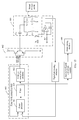
- the apparatus includes a phase-lock control module, an excitation module, a resonance module, a signal collection module, and a determining module, where an output end of the phase-lock control module is connected to all of a first input end of the phase-lock control module, an input end of the excitation module, and an input end of the determining module, a second input end of the phase-lock control module is connected to an output end of the signal collection module, an input end of the signal collection module is connected to an output end of the resonance module, and an input end of the resonance module is connected to an output end of the excitation module.
- the determining module may determine, based on the frequency-adjusted first signal and the pre-stored fourth signal, whether there is a metal foreign matter in the area of the target coil, or determine, based on the difference between the phase of the first signal and the phase of the third signal and the fourth signal, whether there is a metal foreign matter in the area of the target coil.
- a metal foreign matter in a wireless charging system (particularly, an electromagnetically induced non-contact wireless charging system), that is, there is a metal foreign matter on a surface of a transmit coil of a wireless charger or a surface of a receive coil of a to-be-charged device, and an induced current exists in the transmit coil or the receive coil, an eddy current is generated in the metal foreign matter due to electromagnetic induction.
- the metal becomes hot, and even the metal suffers spontaneous combustion or other objects near the metal foreign matter burn, causing potential safety hazards to the wireless charging system and objects surrounding the wireless charging system.
- Wireless energy transmission may be performed between the wireless charging transmitting apparatus 211 and the wireless charging receiving apparatus 221 in an electric field or magnetic field coupling manner, for example, in an electric field induction manner, a magnetic induction manner, a magnetic resonance manner, or a wireless radiation manner, to implement non-contact wireless charging.
- a manner of wireless energy transmission between the wireless charging transmitting apparatus 211 and the wireless charging receiving apparatus 221 is not specifically limited in this embodiment of this application.
- the receive control module 322 is configured to control a voltage, a current, and a frequency of the receive conversion module 323 based on an actual requirement for wireless charging receive power.
- the receive communications module 324 is configured to perform wireless communication between the wireless charging transmitting apparatus 211 and the wireless charging receiving apparatus 221, including communication of information such as power control information, fault protection information, power-on/power-off information, and mutual authentication information.
- the third signal that is output by the resonance module 403 is relatively weak, that is, sensitivity of metal foreign matter detection is relatively low.
- a size of a wireless charging transmit coil of an electric automobile is at least 20 cm ⁇ 20 cm, and one foreign-matter detection coil whose size is equivalent to that of the transmit coil is separately used for detection, but a metal foreign matter is only the same as a 5-jiao coin or a 1-jiao coin in size.
- the excitation module 402 sequentially outputs excitation signals that enable resonances to occur in the resonant circuit including the foreign-matter detection coils in the foreign-matter detection coil array and the at least one resonant capacitor.
- Voltage values of the foreign-matter detection coils when the resonance occurs are sequentially measured, where X ranges from 1 to 9, and Y ranges from 1 to 6; and then, the voltage values are stored to a memory. For example, for V (3, 4) and V (8, 5) shown in FIG.
- the apparatus 400 may further include a charging control module 406.
- the charging control module 406 is connected to all of the at least one switch, the output end of the determining module 405, and the transmit coil, and is configured to: control a status of the at least one switch, and control a working status of the transmit coil based on a determining result of the determining module 405; or the charging control module 406 is connected to all of the at least one switch, the output end of the determining module 405, and the receive coil, and is configured to: control a status of the at least one switch, and control a working status of the receive coil based on a determining result of the determining module.
- the signal processing module may be a zero-crossing detection circuit.
- the zero-crossing detection circuit is configured to generate and output a square wave signal corresponding to the third signal, based on the third signal that is output by the resonance module.
- a point with an amplitude 0 in the square wave signal corresponding to the third signal is the same as a point with an amplitude 0 in the third signal.
- the signal processing module may be an analog-to-digital conversion module, configured to convert the third signal into a digital signal.
Abstract
Description
- This application claims priority to Chinese Patent Application No.
201810668923.2 - This application relates to the field of wireless charging technologies, and in particular, to an apparatus and a method for detecting a metal foreign matter in a wireless charging system, and a device.
- In wireless charging technologies, energy transmission is performed by using an electromagnetic field or an electromagnetic wave, so that a charger is not limited by a line, thereby implementing complete separation between a to-be-charged device and a power source. Therefore, such a charger has advantages over a conventional charger in safety (for example, no electric spark and no electric shock risk), flexibility (for example, being adapted to a variety of adverse circumstances and facilitating implementation of unmanned automatic charging and mobile charging), and other aspects.
- However, when there is a metal foreign matter between a transmit coil of a wireless charger and a receive coil of a to-be-charged device and a current exists in the transmit coil or the receive coil, an eddy current is generated in the metal foreign matter due to electromagnetic induction. As a result, the metal becomes hot, and even the metal may suffer spontaneous combustion (for example, tin foil paper suffers spontaneous combustion when a temperature of the tin foil paper reaches a specific high temperature) or other objects near the metal foreign matter may burn (leaves, scraps of paper, and the like that are on the metal foreign matter burn because the metal becomes hot). Therefore, to ensure safety of the wireless charger and the to-be-charged device in a wireless charging system, whether there is a metal foreign matter between the transmit coil of the wireless charger and the receive coil of the to-be-charged device needs to be detected.
- In the prior art, a resonant circuit including a foreign-matter detection coil and a resonant capacitor is usually used to detect whether there is a metal foreign matter between the transmit coil of the wireless charger and the receive coil of the to-be-charged device. When there is no metal foreign matter between the transmit coil of the wireless charger and the receive coil of the to-be-charged device, an inductance of the foreign-matter detection coil is L1. When there is a metal foreign matter between the transmit coil of the wireless charger and the receive coil of the to-be-charged device, an inductance of a foreign-matter sensing coil changes to L2 due to mutual inductance, and then a resonance frequency of the resonant circuit, an amplitude of a signal that is output by the resonant circuit, and a phase of the signal that is output by the resonant circuit change. In this case, when a resonance occurs in the resonant circuit under excitation of signals at different frequencies that are output by a frequency sweeping excitation source, a parameter of the output signal if there is a metal foreign matter between the transmit coil of the wireless charger and the receive coil of the to-be-charged device is compared with a parameter of the output signal if there is no metal foreign matter between the transmit coil of the wireless charger and the receive coil of the to-be-charged device, to determine whether there is a metal foreign matter between the transmit coil of the wireless charger and the receive coil of the to-be-charged device.
- However, when the resonant circuit including the foreign-matter detection coil and the resonant capacitor is used to detect whether there is a metal foreign matter between the transmit coil of the wireless charger and the receive coil of the to-be-charged device, each area of the transmit coil of the wireless charger needs to be detected through frequency sweeping excitation, a frequency of the excitation source needs to be adjusted during each detection to make a resonance occur in the resonant circuit, and then a corresponding parameter is obtained. As a result, both a data computation amount (such as fast Fourier transform analysis) and a data storage amount are quite large, and requirements for hardware and software are higher, causing great implementation difficulty.
- This application provides an apparatus and a method for detecting a metal foreign matter in a wireless charging system, and a device, to resolve a prior-art problem of a relatively large data computation amount and data storage amount in a solution for detecting a metal foreign matter in a wireless charging system.
- According to a first aspect, this application provides an apparatus for detecting a metal foreign matter in a wireless charging system. The wireless charging system includes a wireless charger and a to-be-charged device. The apparatus includes a phase-lock control module, an excitation module, a resonance module, a signal collection module, and a determining module, where an output end of the phase-lock control module is connected to all of a first input end of the phase-lock control module, an input end of the excitation module, and an input end of the determining module, a second input end of the phase-lock control module is connected to an output end of the signal collection module, an input end of the signal collection module is connected to an output end of the resonance module, and an input end of the resonance module is connected to an output end of the excitation module;
the phase-lock control module is configured to output a first signal to the excitation module, where the first signal is used to control a frequency of a second signal generated by the excitation module; the excitation module is configured to: generate the second signal based on the first signal, and output the second signal to the resonance module, where the frequency of the second signal is determined based on a frequency of the first signal, and the second signal is used to excite the resonance module; the resonance module includes at least one foreign-matter detection coil and at least one resonant capacitor, and is configured to generate a third signal under excitation of the second signal by using a resonant circuit including a target coil and a target capacitor, where the at least one foreign-matter detection coil is connected to the at least one resonant capacitor, the target coil is one or more of the at least one foreign-matter detection coil, the target capacitor is one or more of the at least one resonant capacitor, the at least one foreign-matter detection coil is distributed above a transmit coil of the wireless charger or a receive coil of the to-be-charged device, and an area of the at least one foreign-matter detection coil can cover an area of the transmit coil or an area of the receive coil; the signal collection module is configured to: collect the third signal, and output the third signal to the phase-lock control module; the phase-lock control module is further configured to adjust the frequency of the output first signal based on a difference between a phase of the first signal and a phase of the third signal, where a difference between a phase of the frequency-adjusted first signal and the phase of the third signal is less than a first specified value, and a frequency of the second signal that is generated by the excitation module based on the frequency-adjusted first signal is the same as a resonance frequency of the resonant circuit; and
the determining module is configured to determine, based on the frequency-adjusted first signal and a corresponding parameter value of a pre-stored fourth signal, whether there is a metal foreign matter in an area of the target coil, where the fourth signal is a signal that is output by the resonant circuit in a resonant state when there is no metal foreign matter in the area of the target coil. - According to the solution, the apparatus for detecting a metal foreign matter in the wireless charging system can control, by using the first signal that is output by the phase-lock control module, the frequency of the second signal that is output by the excitation module and that is used to excite the resonance module; and the phase-lock control module can adjust the frequency of the first signal that is output by the phase-lock control module, based on the third signal that is output by the resonance module under excitation of the second signal and that is collected by the signal collection module and the first signal that is output by the phase-lock control module. Because the difference between the phase of the adjusted first signal and the phase of the third signal is less than the first specified value, the frequency of the second signal that is generated and output by the excitation module reaches the resonance frequency of the resonant circuit that is in the resonance module and that includes the target coil and the target resonant capacitor, and then a resonance occurs. In this case, the determining module may determine, based on the frequency-adjusted first signal that is output by the phase-lock control module and the pre-stored fourth signal, whether there is a metal foreign matter in the area of the target coil, or determine, based on the difference between the phase of the first signal and the phase of the third signal and the fourth signal, whether there is a metal foreign matter in the area of the target coil.
- In other words, through closed-loop control of the phase-lock control module, the apparatus for detecting a metal foreign matter in the wireless charging system provided in this embodiment of this application can make the second signal that is output by the excitation module excite the resonant circuit that is in the resonance module and that includes the target coil and the target capacitor, to cause a resonance. In this way, frequency sweeping excitation, complex computation and analysis, and a large amount of data processing do not need to be performed to obtain the resonance frequency of the resonant circuit including the foreign-matter detection coil, to make a resonance occur in the resonant circuit. In comparison with the prior art, control precision is higher and a computation amount is smaller in this embodiment of this application. This can effectively simplify a metal foreign matter detection process in the wireless charging system.
- In a possible implementation, the determining module is specifically configured to: when a difference between a frequency of the frequency-adjusted first signal and a frequency of the fourth signal is less than a second specified value, determine that there is no metal foreign matter in the area of the target coil; or when a difference between a frequency of the frequency-adjusted first signal and a frequency of the fourth signal is greater than or equal to the second specified value, determine that there is a metal foreign matter in the area of the target coil.
- In a possible implementation, the phase-lock control module may be a phase-locked loop chip, or may be implemented by a combination of discrete devices or a combination of corresponding chips. When the phase-lock control module is implemented by a combination of discrete devices or a combination of corresponding chips, the implementation may include but is not limited to any one of the following several manners:
- Manner 1: The phase-lock control module may include a phase detector and a voltage-controlled oscillator. An input end of the voltage-controlled oscillator is connected to an output end of the phase detector, an output end of the voltage-controlled oscillator is connected to all of a first input end of the phase detector, the input end of the determining module, and the input end of the excitation module, and a second input end of the phase detector is connected to the output end of the signal collection module, where
the phase detector is configured to: generate a fifth signal based on the difference between the phase of the first signal and the phase of the third signal, and output the fifth signal to the voltage-controlled oscillator; and
the voltage-controlled oscillator is configured to generate the frequency-adjusted first signal based on the fifth signal. - Manner 2: The phase-lock control module may include a phase detector and a voltage-controlled oscillator. An output end of the voltage-controlled oscillator is connected to both a first input end of the phase detector and the input end of the excitation module, a second input end of the phase detector is connected to the output end of the signal collection module, and an output end of the phase detector is connected to both an input end of the voltage-controlled oscillator and the input end of the determining module, where
the phase detector is configured to: generate a fifth signal based on the difference between the phase of the first signal and the phase of the third signal, and output the fifth signal to the voltage-controlled oscillator and the determining module; and
the voltage-controlled oscillator is configured to generate the frequency-adjusted first signal based on the fifth signal. - Manner 3: The phase-lock control module may include a phase detector, a filter, and a voltage-controlled oscillator. An output end of the voltage-controlled oscillator is connected to both a first input end of the phase detector and the input end of the excitation module, a second input end of the phase detector is connected to the output end of the signal collection module, an output end of the phase detector is connected to an input end of the filter, and an output end of the filter is connected to both an input end of the voltage-controlled oscillator and the input end of the determining module, where
the phase detector is configured to: generate a fifth signal based on the difference between the phase of the first signal and the phase of the third signal, and output the fifth signal to the filter;
the filter is configured to: filter out a harmonic component of the fifth signal, and output a filtered fifth signal to the voltage-controlled oscillator and the determining module; and
the voltage-controlled oscillator is configured to generate the frequency-adjusted first signal based on the filtered fifth signal. - In a possible implementation, the phase-lock control module in Manner 1 or Manner 2 may further include a filter. An input end of the filter is connected to the output end of the phase detector, and an output end of the filter is connected to the input end of the voltage-controlled oscillator; and the filter is configured to: filter out a harmonic component of the fifth signal, and output a filtered fifth signal to the voltage-controlled oscillator.
- According to the solution, the filter can filter out an interfering signal in the fifth signal, to improve control precision of the phase-lock control module, so that the phase of the first signal is closer to the phase of the third signal.
- In a possible implementation, when the phase-lock control module is of the structure described in Manner 2, the determining module is specifically configured to: when a difference between an amplitude of the fifth signal and an amplitude of the fourth signal is less than a second specified value, determine that there is no metal foreign matter in the area of the target coil; or when a difference between corresponding parameter values of the fifth signal and the fourth signal is greater than or equal to the second specified value, determine that there is a metal foreign matter in the area of the target coil.
- In a possible implementation, when the phase-lock control module is of the structure described in Manner 3, the determining module is specifically configured to: when a difference between an amplitude of the filtered fifth signal and an amplitude of the fourth signal is less than a second specified value, determine that there is no metal foreign matter in the area of the target coil; or when a difference between corresponding parameter values of the filtered fifth signal and the fourth signal is greater than or equal to a second specified value, determine that there is a metal foreign matter in the area of the target coil.
- In a possible implementation, the excitation module may be implemented, for example, in either of the following two manners:
- Manner A: The excitation module may be a first power amplifier. An output end of the first power amplifier is connected to both a first input end of the first power amplifier and the input end of the resonance module, and a second input end of the first power amplifier is connected to the output end of the phase-lock control module.
- Manner B: The excitation module may be a voltage-type converter or a current-type converter. The voltage-type converter and the current-type converter each may be a half bridge converter, a full bridge converter, or another circuit structure. When the third signal that is output by the excitation module cannot drive the voltage-type converter and the current-type converter, the excitation module may further include a second power amplifier. An output end of the second power amplifier is connected to both a first output end of the second power amplifier and an input end of the voltage-type converter (or the current-type converter), and an output end of the voltage-type converter (or the current-type converter) is connected to the input end of the resonance module.
- Manner C: The excitation module may be an amplification circuit (for example, a push-pull circuit) including components such as transistors.
- In a possible implementation, the resonance module further includes at least one switch, and the at least one foreign-matter detection coil and the at least one resonant capacitor are connected in parallel and/or in series through the at least one switch.
- In a possible implementation, to detect a plurality of types of metal foreign matters made of different materials and further improve accuracy of a detection result, the resonance module includes a plurality of resonant capacitors. The plurality of resonant capacitors are connected to the at least one foreign-matter detection coil through the at least one switch, so that one target coil and capacitors with different capacitances may form a resonant circuit with different resonance frequencies, thereby implementing detection of metal foreign matters made of different materials.
- In a possible implementation, the target coil and the target capacitor in the resonance module may form an LC series resonant circuit; the target coil and the target capacitor may form an LC parallel resonant circuit; the target coil and the target capacitor may form an LCC resonant circuit; the target coil and the target capacitor may form a CCL resonant circuit; or the resonance module further includes at least one resonant inductor, and the target coil, the target capacitor, and the at least one resonant inductor may form an LCL resonant circuit.
- In a possible implementation, the apparatus may further include a charging control module. The charging control module is connected to all of the at least one switch, an output end of the determining module, and the transmit coil, and is configured to: control a status of the at least one switch, and control a working status of the transmit coil based on a determining result of the determining module; or the charging control module is connected to all of the at least one switch, an output end of the determining module, and the receive coil, and is configured to: control a status of the at least one switch, and control a working status of the receive coil based on a determining result of the determining module.
- In a possible implementation, the apparatus may further include a signal processing module. An input end of the signal processing module is connected to the output end of the signal collection module, and an output end of the signal processing module is connected to the second input end of the phase-lock control module; and when the first signal that is output by the phase-lock control module is a digital signal, the signal processing module is configured to: convert the third signal into a digital signal, and output the digital signal corresponding to the third signal to the second input end of the phase-lock control module.
- In a possible implementation, when a type of the first signal (a digital signal or an analog signal) output by the phase-lock control module is different from a type of the fourth signal stored in the determining module, the apparatus further includes a digital-to-analog conversion module or an analog-to-digital conversion module, so that the type of the signal to be compared by the determining module is the same as that of the fourth signal.
- According to a second aspect, this application further provides a method for detecting a metal foreign matter in a wireless charging system, where the method is applied to an apparatus for detecting a metal foreign matter in the wireless charging system. The apparatus includes a phase-lock control module, an excitation module, a resonance module, a signal collection module, and a determining module, where an output end of the phase-lock control module is connected to all of a first input end of the phase-lock control module, an input end of the excitation module, and an input end of the determining module, a second input end of the phase-lock control module is connected to an output end of the signal collection module, an input end of the signal collection module is connected to an output end of the resonance module, and an input end of the resonance module is connected to an output end of the excitation module. The method includes:
outputting, by the phase-lock control module, a first signal to the excitation module, where the first signal is used to control a frequency of a second signal generated by the excitation module; generating, by the excitation module, the second signal based on the first signal, and outputting the second signal to the resonance module, where the frequency of the second signal is determined based on a frequency of the first signal, and the second signal is used to excite the resonance module; generating, by a resonant circuit including a target coil and a target capacitor in the resonance module, a third signal under excitation of the second signal, where the resonance module includes at least one foreign-matter detection coil and at least one resonant capacitor, the at least one foreign-matter detection coil is connected to the at least one resonant capacitor, the target coil is one or more of the at least one foreign-matter detection coil, the target capacitor is one or more of the at least one resonant capacitor, the at least one foreign-matter detection coil is distributed above a transmit coil of the wireless charger or a receive coil of the to-be-charged device, and an area of the at least one foreign-matter detection coil can cover an area of the transmit coil or an area of the receive coil; collecting, by the signal collection module, the third signal, and outputting the collected third signal to the phase-lock control module; adjusting, by the phase-lock control module, the frequency of the output first signal based on a difference between a phase of the first signal and a phase of the third signal, where a difference between a phase of the frequency-adjusted first signal and the phase of the third signal is less than a first specified value, and a frequency of the second signal that is generated by the excitation module based on the frequency-adjusted first signal is the same as a resonance frequency of the resonant circuit; and determining, by the determining module based on the frequency-adjusted first signal and a pre-stored fourth signal, whether there is a metal foreign matter in an area of the target coil, or determining, based on the fourth signal and the difference between the phase of the first signal and the phase of the third signal, whether there is a metal foreign matter in an area of the target coil, where the fourth signal is a signal that is output by the resonant circuit in a resonant state when there is no metal foreign matter in the area of the target coil. - According to the method, the phase-lock control module controls, by using the output first signal, the frequency of the second signal that is output by the excitation module and that is used to excite the resonance module; and the phase-lock control module can further adjust the frequency of the first signal that is output by the phase-lock control module, based on the third signal that is output by the resonance module under excitation of the second signal and that is collected by the signal collection module and the first signal that is output by the phase-lock control module. Because the difference between the phase of the adjusted first signal and the phase of the third signal is less than the first specified value, the frequency of the second signal that is generated and output by the excitation module reaches the resonance frequency of the resonant circuit that is in the resonance module and that includes the target coil and the target resonant capacitor, and then a resonance occurs. In this case, the determining module may determine, based on the frequency-adjusted first signal and the pre-stored fourth signal, whether there is a metal foreign matter in the area of the target coil, or determine, based on the difference between the phase of the first signal and the phase of the third signal and the fourth signal, whether there is a metal foreign matter in the area of the target coil.
- In a possible implementation, the determining module may use the following method to determine whether there is a metal foreign matter in the area of the target coil: when a difference between a frequency of the frequency-adjusted first signal and a frequency of the fourth signal is less than a second specified value, determining, by the determining module, that there is no metal foreign matter in the area of the target coil; or when a difference between a frequency of the frequency-adjusted first signal and a frequency of the fourth signal is greater than or equal to the second specified value, determining, by the determining module, that there is a metal foreign matter in the area of the target coil.
- In a possible implementation, the phase-lock control module adjusts the frequency of the output first signal according to the following steps: generating, by the phase-lock control module, a fifth signal based on the difference between the phase of the first signal and the phase of the third signal, and generating the frequency-adjusted first signal based on the fifth signal.
- In a possible implementation, the determining module may use the following method to determine whether there is a metal foreign matter in the area of the target coil: when a difference between an amplitude of the fifth signal and an amplitude of the fourth signal is less than a second specified value, determining, by the determining module, that there is no metal foreign matter in the area of the target coil; or when a difference between an amplitude of the fifth signal and an amplitude of the fourth signal is greater than or equal to the second specified value, determining, by the determining module, that there is a metal foreign matter in the area of the target coil.
- In a possible implementation, the resonance module further includes at least one switch, and the at least one foreign-matter detection coil and the at least one resonant capacitor are connected in parallel and/or in series through the at least one switch; the apparatus further includes a charging control module, and in a scenario in which the charging control module is connected to all of the at least one switch, an output end of the determining module, and the transmit coil, before the excitation module outputs the second signal to the resonance module, the charging control module controls a status of the at least one switch, and selects the target coil and the target capacitor; and after the determining module determines whether there is a metal foreign matter in the area of the target coil, the charging control module may further control a working status of the transmit coil based on a determining result of the determining module.
- In a possible implementation, the resonance module further includes at least one switch, and the at least one foreign-matter detection coil and the at least one resonant capacitor are connected in parallel and/or in series through the at least one switch; the apparatus further includes a charging control module, and in a scenario in which the charging control module is connected to all of the at least one switch, an output end of the determining module, and the transmit coil, before the excitation module outputs the second signal to the resonance module, the charging control module controls a status of the at least one switch, and selects the target coil and the target capacitor; and after the determining module determines whether there is a metal foreign matter in the area of the target coil, the charging control module may further control a working status of the receive coil based on a determining result of the determining module.
- According to a third aspect, this application further provides a wireless charger. The wireless charger includes the apparatus for detecting a metal foreign matter in the wireless charging system provided in any implementation of the first aspect.
- According to a fourth aspect, this application further provides a device supporting a wireless charging function. The device supporting a wireless charging function includes the apparatus for detecting a metal foreign matter in the wireless charging system provided in any implementation of the first aspect.
-
-
FIG. 1 is a schematic structural diagram of a wireless charging system according to an embodiment of this application; - FIG. 2 is a schematic structural diagram of a wireless charging system for charging an electric automobile according to an embodiment of this application;
-
FIG. 3 is a schematic structural diagram of a wireless charging transmitting apparatus and a wireless charging receiving apparatus according to an embodiment of this application; -
FIG. 4 shows an apparatus for detecting a metal foreign matter in a wireless charging system according to an embodiment of this application; -
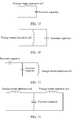
FIG. 5 is a schematic structural diagram of a first type of phase-lock control module according to an embodiment of this application; -
FIG. 6 is a schematic structural diagram of a second type of phase-lock control module according to an embodiment of this application; -
FIG. 7 is a schematic structural diagram of a third type of phase-lock control module according to an embodiment of this application; -
FIG. 8 is a schematic structural diagram of a first type of excitation module according to an embodiment of this application; -
FIG. 9 is a schematic structural diagram of a second type of excitation module according to an embodiment of this application; -
FIG. 10 is a schematic structural diagram of a third type of excitation module according to an embodiment of this application; -
FIG. 11a is a schematic distribution diagram of a foreign-matter detection coil according to an embodiment of this application; -
FIG. 11b is a schematic distribution diagram of a foreign-matter detection coil according to an embodiment of this application; -
FIG. 12 shows a detection result of a foreign-matter detection coil when there is no metal foreign matter according to an embodiment of this application; -
FIG. 13 is a schematic structural diagram of an excitation module according to an embodiment of this application; -
FIG. 14 is a schematic structural diagram of another excitation module according to an embodiment of this application; -
FIG. 15 is a schematic structural diagram of an LC series resonant circuit according to an embodiment of this application; -
FIG. 16 is a schematic structural diagram of an LC parallel resonant circuit according to an embodiment of this application; -
FIG. 17 is a schematic structural diagram of an LCC resonant circuit according to an embodiment of this application; and -
FIG. 18 is a schematic structural diagram of an LCL resonant circuit according to an embodiment of this application. - When there is a metal foreign matter in a wireless charging system (particularly, an electromagnetically induced non-contact wireless charging system), that is, there is a metal foreign matter on a surface of a transmit coil of a wireless charger or a surface of a receive coil of a to-be-charged device, and an induced current exists in the transmit coil or the receive coil, an eddy current is generated in the metal foreign matter due to electromagnetic induction. As a result, the metal becomes hot, and even the metal suffers spontaneous combustion or other objects near the metal foreign matter burn, causing potential safety hazards to the wireless charging system and objects surrounding the wireless charging system.
- In the prior art, a resonant circuit including a foreign-matter detection coil and a resonant capacitor is usually used to detect whether there is a metal foreign matter between the transmit coil of the wireless charger and the receive coil of the to-be-charged device. However, when the resonant circuit including the foreign-matter detection coil and the resonant capacitor is used to detect whether there is a metal foreign matter between the transmit coil of the wireless charger and the receive coil of the to-be-charged device, each area of the transmit coil of the wireless charger needs to be detected through frequency sweeping excitation, a frequency of the excitation source needs to be adjusted during each detection to make a resonance occur in the resonant circuit, and then a corresponding parameter is obtained. As a result, both a data computation amount (such as fast Fourier transform analysis) and a data storage amount are quite large, and requirements for hardware and software that are used for detection are relatively high.
- To resolve the foregoing prior-art problems, this application provides an apparatus and a method for detecting a metal foreign matter in a wireless charging system, and a device. The method and the apparatus are based on a same inventive concept. A problem-resolving principle of the method is similar to that of the apparatus, and therefore an apparatus embodiment and a method apparatus can be mutually referenced. Repetition is not elaborated again.
- It should be understood that in the descriptions of the embodiments of this application, "a plurality of" means two or more; terms such as "first" and "second" are only used for description differentiation, but cannot be understood as indication or implication of relative importance and cannot be understood as indication or implication of sequences.
- The apparatus and the method for detecting a metal foreign matter in the wireless charging system, and the device that are provided in this application are applicable to at least one of the following scenarios: Before a wireless charger charges a to-be-charged device (a device supporting a wireless charging function), whether there is a metal foreign matter on a surface of a transmit coil of the wireless charger or a surface of a receive coil of the to-be-charged device is detected, and then whether a charging function of the wireless charger or a charging function of the to-be-charged device is to be enabled is determined. In a process of charging the to-be-charged device by the wireless charger, whether there is a metal foreign matter on a surface of a transmit coil of the wireless charger or a surface of a receive coil of the to-be-charged device is detected, and then whether transmit power of the wireless charger is to be adjusted is determined or whether a charging function of the wireless charger is to be disabled (or whether a charging function of the to-be-charged device is to be disabled) is determined. Generally, when the wireless charging system works, the to-be-charged device is located above the wireless charger, and a probability that there is a metal foreign matter on the surface of the transmit coil of the wireless charger is relatively high. Therefore, the apparatus and the method for detecting a metal foreign matter in the wireless charging system, and the device that are provided in this application are mainly used to detect whether there is a metal foreign matter on the surface of the transmit coil of the wireless charger.
- As shown in
FIG. 1 , the apparatus and the method for detecting a metal foreign matter in the wireless charging system, and the device that are provided in this application are applied to the wireless charging system. The wireless charging system includes awireless charger 101 and a to-be-charged device 102 supporting a wireless charging function. Thewireless charger 101 is connected to a power source, and is configured to send energy of the power source connected to thewireless charger 101 to the to-be-charged device 102 in a form of an electromagnetic wave. The to-be-charged device 102 is configured to receive the electromagnetic wave sent by the wireless charger, and the to-be-charged device is charged by using the energy in the form of the received electromagnetic wave. - The following details the wireless charging system by using an example in which the
wireless charger 101 is a wireless charging station and the to-be-charged device 102 is an electric automobile. - As shown in FIG. 2, the
wireless charging station 210 includes a wirelesscharging transmitting apparatus 211. Thewireless charging station 210 may be a fixed wireless charging station, a fixed wireless parking space, a wireless charging road, or the like. The wirelesscharging transmitting apparatus 211 may be disposed on the ground, half-buried in the ground, or buried beneath the ground (FIG. 2 illustrates a case in which the wirelesscharging transmitting apparatus 211 is buried beneath the ground), and is configured to wirelessly charge anelectric automobile 220 located above the wirelesscharging transmitting apparatus 211. The wirelesscharging transmitting apparatus 211 includes a power transmit coil and an inverter circuit. The power transmit coil and the inverter circuit may be integrated, or may be disposed separately. Thewireless charging station 210 may be disposed in various scenarios such as a parking lot, a private parking space, and a platform of a charging station. - The
electric automobile 220 includes a wirelesscharging receiving apparatus 221, and the wirelesscharging receiving apparatus 221 may be integrated on a bottom of theelectric automobile 220. When theelectric automobile 220 enters a wireless charging range of the wirelesscharging transmitting apparatus 211, theelectric automobile 220 can be charged in a wireless charging manner. The wirelesscharging receiving apparatus 221 includes a power receive coil and a rectifier circuit. The power receive coil and the rectifier circuit may be integrated, or may be disposed separately. When the power receive coil and the rectifier circuit in the wirelesscharging receiving apparatus 221 are separated, a rectifier module of the wirelesscharging receiving apparatus 221 is usually disposed within the automobile. - Wireless energy transmission may be performed between the wireless
charging transmitting apparatus 211 and the wirelesscharging receiving apparatus 221 in an electric field or magnetic field coupling manner, for example, in an electric field induction manner, a magnetic induction manner, a magnetic resonance manner, or a wireless radiation manner, to implement non-contact wireless charging. A manner of wireless energy transmission between the wirelesscharging transmitting apparatus 211 and the wirelesscharging receiving apparatus 221 is not specifically limited in this embodiment of this application. - Further, two-way charging may alternatively be implemented between the
electric automobile 220 and thewireless charging station 210. To be specific, thewireless charging station 210 may charge theelectric automobile 220 by using a power source, or theelectric automobile 220 may charge the power source. -
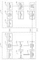
FIG. 3 (left) is a schematic structural diagram of the wirelesscharging transmitting apparatus 211 in thewireless charging station 210. The wirelesscharging transmitting apparatus 211 includes a transmitconversion module 311, a power transmitcoil 312, a transmitcontrol module 313, a transmitcommunications module 314, anauthentication management module 315, and astorage module 316, where
the transmitconversion module 311 may be connected to a power source, and is configured to: obtain energy from the power source, and convert an alternating current or direct current power supply of the power source into a high-frequency alternating current. When the power source is an alternating current input end, the transmitconversion module 311 includes a power factor correction unit (not shown inFIG. 3 ) and an inverter unit (not shown inFIG. 3 ). When the power source is a direct current input end, the transmitconversion module 311 includes an inverter unit (not shown inFIG. 3 ) and a voltage conversion unit (not shown inFIG. 3 ). - The power factor correction unit is configured to ensure that a phase of an input current of the wireless charging system is consistent with a phase of a power grid voltage, reduce system harmonic content, and increase a power factor value, thereby reducing impact of the wireless charging system on a power grid and improving reliability. The power factor correction unit may further increase or decrease an output voltage of the power factor correction unit depending on a next-stage device requirement. The inverter unit may convert the voltage output by the power factor correction unit into a high-frequency alternating current voltage, and apply the high-frequency alternating current voltage to the power transmit coil. The high-frequency alternating current voltage can greatly improve transmission efficiency and increase a transmission distance. It should be noted that the power source may be a power source inside the wireless
charging transmitting apparatus 211, or may be an external power source connected to the wirelesscharging transmitting apparatus 211. - The power transmit
coil 312 is configured to convert the high-frequency alternating current into a resonance voltage and current by using a network constituted by components mainly including an inductor and a capacitor. - The transmit
control module 313 is configured to: based on an actual requirement for wireless charging transmit power, control a voltage, a current, and a frequency that are output by the transmit conversion module, and control the voltage and a current of the high-frequency alternating current in the power transmitcoil 312. - The transmit
communications module 314 is configured to perform wireless communication between the wirelesscharging transmitting apparatus 211 and the wirelesscharging receiving apparatus 221, including communication of information such as power control information, fault protection information, power-on/power-off information, and mutual authentication information. The wirelesscharging transmitting apparatus 211 may receive attribute information, a charging request, and mutual authentication information of the electric automobile that are sent by the wireless charging receiving apparatus. In addition, the wirelesscharging transmitting apparatus 211 may further send wireless charging transmit control information, mutual authentication information, wireless charging historical data information, or the like to the wirelesscharging receiving apparatus 221. A manner of wireless communication between the wirelesscharging transmitting apparatus 211 and the wirelesscharging receiving apparatus 221 may include but is not limited to any one or a combination of the following: a Bluetooth (bluetooth) technology, a wireless fidelity (wireless-fidelity, WiFi) technology, aZigBee (Zigbee)-based wireless communications technology, a radio frequency identification (radio frequency identification, RFID) technology, a long range (long range, Lora) wireless technology, and near field communication (near field communication, NFC). Further, the transmitcommunications module 314 may further communicate with an intelligent terminal of a user to which theelectric automobile 220 belongs, so that the user of the electric automobile can perform remote authentication and user information transmission by using the intelligent terminal. - The
authentication management module 315 is configured to perform mutual authentication and permission management on the wirelesscharging transmitting apparatus 211, theelectric automobile 220, and the wirelesscharging receiving apparatus 221 in the wireless charging system. - The
storage module 316 is configured to store charging process data, mutual authentication data (for example, the mutual authentication information), and permission management data (for example, permission management information) of the wirelesscharging transmitting apparatus 211. The mutual authentication data and the permission management data may be set before delivery, or may be set by a user. -
FIG. 3 (right) is a schematic structural diagram of the wirelesscharging receiving apparatus 221 in theelectric automobile 220. The wirelesscharging receiving apparatus 221 includes a power receivecoil 321, a receivecontrol module 322, a receiveconversion module 323, and a receivecommunications module 324. - Further, the receive
conversion module 323 may further be connected to an energystorage management module 326 and anenergy storage module 325, and charge theenergy storage module 325 by using energy received by the receiveconversion module 323, to further drive the electric automobile. It should be noted that the energystorage management module 326 and theenergy storage module 325 may be located inside the wirelesscharging receiving apparatus 221, or may be located outside the wirelesscharging receiving apparatus 221. This is not specifically limited in this embodiment of this application. - The power receive
coil 321 is configured to receive active power and reactive power transmitted by a transmit end. The power transmitcoil 312 and the power receivecoil 321 in the wireless charging system may be combined selectively. Common network structure combination forms include a series (series)-series type (namely, an S-S type), a parallel (parallel)-parallel type (namely, a P-P type), an S-P type, a P-S type, an LCL-LCL type (where L represents an inductor, and C represents a capacitor), and an LCL-P type. This is not specifically limited in this embodiment of this application. In addition, to implement a two-way charging function of the wireless charging system, both the wirelesscharging transmitting apparatus 211 and the wirelesscharging receiving apparatus 221 may further include a power receive coil and a power transmit coil. The power receive coil and the power transmit coil that are included in the wirelesscharging transmitting apparatus 211 or the wirelesscharging receiving apparatus 221 may be disposed separately or may be integrated. - The receive
control module 322 is configured to control a voltage, a current, and a frequency of the receiveconversion module 323 based on an actual requirement for wireless charging receive power. - The receive
conversion module 323 is configured to convert a high-frequency resonance current and voltage received by the power receive coil into a direct current voltage and a direct current that are required for charging theenergy storage module 325. The receiveconversion module 323 usually includes a rectifier unit (not shown inFIG. 3 ) and a direct current conversion unit (not shown inFIG. 3 ). The rectifier unit is configured to convert the high-frequency resonance current and voltage received by the power receive coil into the direct current voltage and the direct current, and the conversion unit is configured to provide the direct current voltage for a next-stage charging circuit, to implement charging in a constant mode. - The receive
communications module 324 is configured to perform wireless communication between the wirelesscharging transmitting apparatus 211 and the wirelesscharging receiving apparatus 221, including communication of information such as power control information, fault protection information, power-on/power-off information, and mutual authentication information. - As shown in
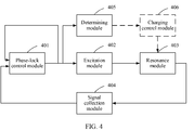
FIG. 4 , an embodiment of this application provides an apparatus for detecting a metal foreign matter in a wireless charging system, where the apparatus is applicable to the wireless charging system shown inFIG. 1 to FIG. 3 . The apparatus 400 includes a phase-lock control module 401, anexcitation module 402, aresonance module 403, asignal collection module 404, and a determiningmodule 405, where an output end of the phase-lock control module 401 is connected to all of a first input end of the phase-lock control module 401, an input end of theexcitation module 402, and an input end of the determiningmodule 405, a second input end of the phase-lock control module 401 is connected to an output end of thesignal collection module 404, an input end of thesignal collection module 404 is connected to an output end of theresonance module 403, and an input end of theresonance module 403 is connected to an output end of theexcitation module 402;
the phase-lock control module 401 is configured to output a first signal to theexcitation module 402, where the first signal is used to control a frequency of a second signal generated by theexcitation module 402;
theexcitation module 402 is configured to: generate the second signal based on the first signal, and output the second signal to theresonance module 403, where the frequency of the second signal is determined based on a frequency of the first signal, and the second signal is used to excite theresonance module 403;
theresonance module 403 includes at least one foreign-matter detection coil and at least one resonant capacitor, and is configured to generate a third signal under excitation of the second signal by using a resonant circuit including a target coil and a target capacitor, where the at least one foreign-matter detection coil is connected to the at least one resonant capacitor, the target coil is one or more of the at least one foreign-matter detection coil, the target capacitor is one or more of the at least one resonant capacitor, the at least one foreign-matter detection coil is distributed above a transmit coil of the wireless charger or a receive coil of the to-be-charged device, and an area of the at least one foreign-matter detection coil can cover an area of the transmit coil or an area of the receive coil;
thesignal collection module 404 is configured to: collect the third signal, and output the third signal to the phase-lock control module 401;
the phase-lock control module 401 is further configured to adjust the frequency of the output first signal based on a difference between a phase of the first signal and a phase of the third signal, where a difference between a phase of the frequency-adjusted first signal and the phase of the third signal is less than a first specified value, and a frequency of the second signal that is generated by theexcitation module 402 based on the frequency-adjusted first signal is the same as a resonance frequency of the resonant circuit; and
the determiningmodule 405 is configured to determine, based on the frequency-adjusted first signal and a pre-stored fourth signal, whether there is a metal foreign matter in an area of the target coil, or determine, based on the fourth signal and the difference between the phase of the first signal and the phase of the third signal, whether there is a metal foreign matter in the area of the target coil, where the fourth signal is a signal that is output by the resonant circuit in a resonant state when there is no metal foreign matter in the area of the target coil. - In a possible implementation, the phase-
lock control module 401 may be a phase-locked loop chip, or may be implemented by a combination of discrete devices or a combination of corresponding chips. When the phase-lock control module 401 is implemented by a combination of discrete devices or a combination of corresponding chips, the implementation may include but is not limited to any one of the following manners: - Manner 1: The phase-
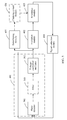
lock control module 401 includes a phase detector and a voltage-controlled oscillator. As shown inFIG. 5 , an input end of the voltage-controlledoscillator 502 is connected to an output end of thephase detector 501, an output end of the voltage-controlledoscillator 502 is connected to all of a first input end of thephase detector 501, the input end of the determiningmodule 405, and the input end of theexcitation module 402, and a second input end of thephase detector 501 is connected to the output end of thesignal collection module 404, where
thephase detector 501 is configured to: generate a fifth signal based on the difference between the phase of the first signal and the phase of the third signal, and output the fifth signal to the voltage-controlledoscillator 502; and
the voltage-controlledoscillator 502 is configured to generate the frequency-adjusted first signal based on the fifth signal.
In a possible implementation, when the phase-lock control module 401 is of the structure shown inFIG. 5 , the determiningmodule 405 is specifically configured to: when a difference between a frequency of the frequency-adjusted first signal and a frequency of the fourth signal is less than a second specified value, determine that there is no metal foreign matter in the area of the target coil; or when a difference between a frequency of the frequency-adjusted first signal and a frequency of the fourth signal is greater than or equal to the second specified value, determine that there is a metal foreign matter in the area of the target coil. - Manner 2: The phase-
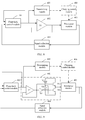
lock control module 401 includes a phase detector and a voltage-controlled oscillator. As shown inFIG. 6 , an output end of the voltage-controlledoscillator 502 is connected to both a first input end of thephase detector 501 and the input end of theexcitation module 402, a second input end of thephase detector 501 is connected to the output end of thesignal collection module 404, and an output end of thephase detector 501 is connected to both an input end of the voltage-controlledoscillator 502 and the input end of the determiningmodule 405, where
thephase detector 501 is configured to: generate a fifth signal based on the difference between the phase of the first signal and the phase of the third signal, and output the fifth signal to the voltage-controlledoscillator 502 and the determiningmodule 405; and
the voltage-controlledoscillator 502 is configured to generate the frequency-adjusted first signal based on the fifth signal.
In a possible implementation, when the phase-lock control module 401 is of the structure shown inFIG. 6 , the determiningmodule 405 is specifically configured to: when a difference between an amplitude of the fifth signal and an amplitude of the fourth signal is less than a second specified value, determine that there is no metal foreign matter in the area of the target coil; or when a difference between corresponding parameter values of the fifth signal and the fourth signal is greater than or equal to the second specified value, determine that there is a metal foreign matter in the area of the target coil.
In a possible implementation, the phase-lock control module 401 inManner 1 orManner 2 may further include afilter 503, as shown inFIG. 5 (orFIG. 6 ). An input end of thefilter 503 is connected to the output end of thephase detector 501, and an output end of thefilter 503 is connected to the input end of the voltage-controlledoscillator 502; and thefilter 503 is configured to: filter out a harmonic component of the fifth signal, and output a filtered fifth signal to the voltage-controlled oscillator. - Manner 3: The phase-
lock control module 401 includes a phase detector, a filter, and a voltage-controlled oscillator. As shown inFIG. 7 , an output end of the voltage-controlledoscillator 502 is connected to both a first input end of thephase detector 501 and the input end of theexcitation module 402, a second input end of thephase detector 501 is connected to the output end of thesignal collection module 404, an output end of thephase detector 501 is connected to an input end of thefilter 503, and an output end of thefilter 503 is connected to both an input end of the voltage-controlledoscillator 502 and the input end of the determiningmodule 405, where
thephase detector 501 is configured to: generate a fifth signal based on the difference between the phase of the first signal and the phase of the third signal, and output the fifth signal to thefilter 503;
thefilter 503 is configured to: filter out a harmonic component of the fifth signal, and output a filtered fifth signal to the voltage-controlledoscillator 502 and the determiningmodule 405; and
the voltage-controlledoscillator 502 is configured to generate the frequency-adjusted first signal based on the filtered fifth signal. - In a possible implementation, when the phase-
lock control module 401 is of the structure shown inFIG. 7 , the determiningmodule 405 is specifically configured to: when a difference between an amplitude of the filtered fifth signal and an amplitude of the fourth signal is less than a second specified value, determine that there is no metal foreign matter in the area of the target coil; or when a difference between an amplitude of the filtered fifth signal and an amplitude of the fourth signal is greater than or equal to a second specified value, determine that there is a metal foreign matter in the area of the target coil. - Further, the
phase detector 501 inManner 1 toManner 3 may be an analog phase detector or a digital phase detector. When a type of the fifth signal (a digital signal or an analog signal) output by the phase-lock control module 401 is different from a type of the fourth signal stored in the determiningmodule 405, the apparatus 400 further includes a digital-to-analog conversion module or an analog-to-digital conversion module, so that the type of the fifth signal to be compared by the determiningmodule 405 is the same as that of the fourth signal. For example, inManner 1, when thephase detector 501 is a digital phase detector and the fourth signal stored in the determiningmodule 405 is an analog signal, the apparatus 400 further includes a digital-to-analog conversion module, where an input end of the digital-to-analog conversion module is connected to the output end of the voltage-controlledoscillator 502, an output end of the digital-to-analog conversion module is connected to an output end of the determining module, and the digital-to-analog conversion module is configured to convert the first signal that is output by the voltage-controlledoscillator 502 into an analog signal. When thephase detector 501 is an analog phase detector and the fourth signal stored in the determiningmodule 405 is a digital signal, the apparatus 400 further includes an analog-to-digital conversion module, where an input end of the analog-to-digital conversion module is connected to the output end of the voltage-controlledoscillator 502, an output end of the analog-to-digital conversion module is connected to an output end of the determining module, and the analog-to-digital conversion module is configured to convert the first signal that is output by the voltage-controlledoscillator 502 into a digital signal. - It should be noted that specific implementations of the
phase detector 501, the digital-to-analog conversion module, and the analog-to-digital conversion module are not limited in this embodiment of this application. Thephase detector 501, the digital-to-analog conversion module, and the analog-to-digital conversion module may be circuits including discrete devices, or may be integrated chips or the like. - In
Manner 1 toManner 3, the voltage-controlledoscillator 502 is configured to convert the fifth signal that is output by thephase detector 501 and that represents the difference between the phase of the first signal and the phase of the third signal into a frequency signal, that is, the first signal. The first signal may be a square wave signal with a variable frequency. A pulse width of the square wave signal with a variable frequency may be fixed or variable. - In
Manner 1 toManner 3, thefilter 503 is mainly configured to filter out a noise signal in the fifth signal, where the noise signal includes a high frequency component and/or a low frequency component, to improve control precision of the phase-lock control module 401. It should be noted that a specific implementation of thefilter 503 is not limited in this embodiment of this application. All integrated chips, chips carrying a corresponding filtering software program, or circuits (active power filters or passive power filters) including discrete devices (for example, a capacitor, an inductor, and a resistor) that can implement the filtering function are applicable to this embodiment of this application. - In a possible implementation, the
excitation module 402 may be implemented, for example, in either of the following two manners: - Manner A: The
excitation module 402 may be a first power amplifier A1. As shown inFIG. 8 , an output end of the first power amplifier A1 is connected to both a first input end of the first power amplifier A1 and the input end of theresonance module 403, and a second input end of the first power amplifier A1 is connected to the output end of the phase-lock control module 401. - Manner B: The
excitation module 402 may be a voltage-type converter or a current-type converter. The voltage-type converter and the current-type converter each may be a half bridge converter, a full bridge converter, or another circuit structure. When the third signal that is output by theexcitation module 402 cannot drive the voltage-type converter and the current-type converter, theexcitation module 402 may further include a second power amplifier. An output end of the second power amplifier is connected to both a first output end of the second power amplifier and an input end of the voltage-type converter (or the current-type converter), and an output end of the voltage-type converter (or the current-type converter) is connected to the input end of theresonance module 403.
For example, when theexcitation module 402 is a half bridge voltage-type converter, a structure of the apparatus 400 is shown inFIG. 9 . Theexcitation module 402 includes a second power amplifier A2, a transistor T1, a transistor T2, a phase inverter B1, a first voltage source V1, and a second voltage source V2. An output end of the second power amplifier A2 is connected to all of a first input end of the second power amplifier, a base of the transistor T1, and an input end of the phase inverter B1; a second input end of the second power amplifier is connected to the output end of the phase-lock control module 401; an output end of the phase inverter is connected to a base of the second transistor T2; a positive electrode of the first voltage source V1 is connected to a collector of the first transistor T1; a negative electrode of the second voltage source V2 is connected to an emitter of the second transistor T2; an emitter of the transistor T1 is connected to both a collector of the second transistor and the input end of theresonance module 403; and a negative electrode of the first voltage source V1 is connected to both a positive electrode of the second voltage source V2 and the output end of theresonance module 403. - Manner C: The
excitation module 402 may be an amplification circuit including components such as transistors. For example, theexcitation module 402 shown inFIG. 10 is a push-pull circuit including a transistor T3 (an NPN transistor) and a transistor T4 (a PNP transistor). A collector of the transistor T3 is connected to a power source Vs, and an emitter of the transistor T3 is connected to an emitter of the transistor T4. A base of the transistor T3 is the input end of theexcitation module 402, and the emitter of the transistor T4 is the output end of theexcitation module 402. - In a possible implementation, the
resonance module 403 may include one foreign-matter detection coil, where the foreign-matter detection coil is distributed above the transmit coil of the wireless charger or the receive coil of the to-be-charged device, and an area of the foreign-matter detection coil can cover the area of the transmit coil or the area of the receive coil. Alternatively, theresonance module 403 may include a foreign-matter detection coil array including a plurality of foreign-matter detection coils, where the foreign-matter detection coil array is distributed above the transmit coil of the wireless charger or the receive coil of the to-be-charged device, and an area of the foreign-matter detection coil array can cover the area of the transmit coil or the area of the receive coil. - Generally, when the wireless charging system works, the to-be-charged device is located above the wireless charger, and a probability that there is a metal foreign matter on a surface of the transmit coil of the wireless charger is relatively high. Therefore, the foreign-matter detection coil (array) is usually arranged on the working surface of the transmit coil of the wireless charger.
- When a metal foreign matter is relatively small and the transmit coil of the wireless charger or the receive coil of the to-be-charged device is relatively large, if only one foreign-matter detection coil is used, the third signal that is output by the
resonance module 403 is relatively weak, that is, sensitivity of metal foreign matter detection is relatively low. For example, a size of a wireless charging transmit coil of an electric automobile is at least 20 cm × 20 cm, and one foreign-matter detection coil whose size is equivalent to that of the transmit coil is separately used for detection, but a metal foreign matter is only the same as a 5-jiao coin or a 1-jiao coin in size. Therefore, to make, as far as possible, whether there is a metal foreign matter detectable at any location of the transmit coil or the receive coil by using the foreign-matter detection coil, a foreign-matter detection coil array including a plurality of foreign-matter detection coils is usually used in a specific implementation process. It should be noted that an arrangement method of the foreign-matter detection coil array, sizes of the foreign-matter detection coils, and shapes of the foreign-matter detection coils are not limited in this embodiment of this application. A shape of each foreign-matter detection coil may be a circle, a rectangle, a square, or another shape. The foreign-matter detection coils in the foreign-matter detection coil array may be evenly distributed above the transmit coil or the receive coil. Alternatively, more foreign-matter detection coils may be arranged in an area of the transmit coil or an area of the receive coil on which relatively great impact is exerted (or an area in which a metal foreign matter appears at a relatively high probability), fewer foreign-matter detection coils may be arranged in an area of the transmit coil or an area of the receive coil on which relatively small impact is exerted (or an area in which a metal foreign matter appears at a relatively low probability). - The smaller sizes of the foreign-matter detection coils in the foreign-matter detection coil array indicate a smaller area of the transmit coil or a smaller area of the receive coil that can be detected by the
apparatus 200 each time, and therefore a metal foreign matter can be positioned more precisely. However, the smaller sizes of the foreign-matter detection coils in the foreign-matter detection coil array indicate a larger quantity of foreign-matter detection coils arranged on the transmit coil or the receive coil. This affects foreign-matter detection efficiency. Therefore, the sizes and a quantity of the foreign-matter detection coils in the foreign-matter detection coil array need to be determined depending on an actual application scenario and a detection target, to balance precision and efficiency of metal foreign matter detection. - For example, as shown in
FIG. 11a , the foreign-matter detection coil array is distributed on the surface of the transmit coil, where the largest rectangle represents the transmit coil, small rectangles represent foreign-matter detection coils, and the foreign-matter detection coils are evenly distributed on the transmit coil. Theoretically, the foreign-matter detection coils need to fully cover the transmit coil (in actual application, an interval between adjacent foreign-matter detection coils is reduced to increase an area of the transmit coil covered by the foreign-matter detection coil array). To clearly illustrate the transmit coil, the foreign-matter detection coils, and a relationship between the foreign-matter detection coils, the transmit coil inFIG. 11a is slightly larger than a coverage area of the foreign-matter detection coil array. In addition, specific intervals are reserved between the foreign-matter detection coils. - In this case, a working principle of the apparatus for detecting a metal foreign matter in the wireless charging system provided in this embodiment of this application is as follows. The determining
module 405 pre-stores voltage values (that is, the fourth signal) that are output by a resonant circuit including the foreign-matter detection coils at different locations on the transmit coil and the resonant capacitor and that are present when there is no metal foreign matter on the transmit coil. The voltage values that are output by the resonant circuit including the foreign-matter detection coils at the different locations on the transmit coil and the resonant capacitor are V (X, Y) = U. X indicates a location of each foreign-matter detection coil in a horizontal coordinate X direction, and Y indicates a location of each foreign-matter detection coil in a vertical coordinate Y direction. For example, V (1, 1) indicates a voltage at the first foreign-matter detection coil in the X direction and the Y direction. - When there is no metal foreign matter on the transmit coil, the
excitation module 402 sequentially outputs excitation signals that enable resonances to occur in the resonant circuit including the foreign-matter detection coils in the foreign-matter detection coil array and the at least one resonant capacitor. Voltage values of the foreign-matter detection coils when the resonance occurs are sequentially measured, where X ranges from 1 to 9, and Y ranges from 1 to 6; and then, the voltage values are stored to a memory. For example, for V (3, 4) and V (8, 5) shown inFIG. 11b , V (3, 4) is corresponding to an induced voltage value of the third foreign-matter detection coil in the X direction and the fourth foreign-matter detection coil in the Y direction, and V (8, 5) is corresponding to an induced voltage value of the eighth foreign-matter detection coil in the X direction and the fifth foreign-matter detection coil in the Y direction. Each foreign-matter detection coil is corresponding to one induced voltage value, and then a three-dimensional view shown inFIG. 12 can further be obtained. When there is no metal foreign matter on the transmit coil, a voltage value of each foreign-matter detection coil is less than a threshold. When there is a metal foreign matter on the transmit coil, it can be detected that a voltage value corresponding to a foreign-matter detection coil having the metal foreign matter is greater than a voltage value detected when there is no metal foreign matter. Detected voltage values of the foreign-matter detection coils at different locations are compared with corresponding voltage values detected when there is no metal foreign matter, and whether a difference between the voltages exceeds the second specified value is determined, to determine whether there is a metal foreign matter on the transmit coil. If the difference between the voltages exceeds the second specified value, it is considered that there is a metal foreign matter in an area of the foreign-matter detection coil (the area of the transmit coil covered by the foreign-matter detection coil). - In a possible implementation, the
resonance module 403 further includes at least one switch, and the at least one foreign-matter detection coil and the at least one resonant capacitor are connected in parallel and/or in series through the at least one switch. For example,FIG. 13 shows theresonance module 403. Theresonance module 403 includes n foreign-matter detection coils L1, L2, ..., and Ln and n switches S1, S2, ..., and Sn, and the n foreign-matter detection coils are connected in parallel respectively through the switches S1, S2, ..., and Sn. When the switch S1 is closed, and S2, S3, ..., and Sn are open, the foreign-matter detection coil L1 (that is, the target coil) and a resonant capacitor Cs (that is, the target capacitor) form a resonant circuit. Theexcitation module 402 applies an alternating current voltage with a frequency of ω and an amplitude of V to the resonant circuit. When there is no metal foreign matter in an area of the foreign-matter detection coil L1, an equivalent impedance of the resonant circuit is

module 405 may compare a current (that is, the fourth signal) of the resonant circuit when there is no metal foreign matter in the area of the foreign-matter detection coil L1 with a current (that is, the third signal) that is detected currently when a resonance occurs in the resonant circuit, to determine whether there is a metal foreign matter in the area of the foreign-matter detection coil L1. By analogy, by controlling statuses of the n switches, the transmit coil or the receive coil covered by the n foreign-matter detection coils can be detected. - In a possible implementation, to detect a plurality of types of metal foreign matters made of different materials and further improve accuracy of a detection result, the
resonance module 403 includes a plurality of resonant capacitors. The plurality of resonant capacitors are connected to the at least one foreign-matter detection coil through the at least one switch, so that one target coil and capacitors with different capacitances may form a resonant circuit with different resonance frequencies, thereby implementing detection of metal foreign matters made of different materials. For example, as shown inFIG. 14 , theresonance module 403 includes n resonant capacitors C1, C2, ..., and Cn, n foreign-matter detection coils L1, L2, ..., and Ln, n switches K1, K2, ..., and Kn, and n switches S1, S2, ..., and Sn. The n resonant capacitors are connected in parallel through the switches K1, K2, ..., and Kn, and the n resonant capacitors are connected in parallel through the switches S1, S2, ..., and Sn. When the switch S1 is closed, and S2, S3 ..., and Sn are open, the switches K1, K2, ..., and Kn are controlled, so that the foreign-matter detection coil L1 and resonant capacitors with different capacitances can form an LC series resonant circuit. - Further, the target coil and the target capacitor in the
resonance module 403 may form an LC series resonant circuit, as shown inFIG. 15 ; the target coil and the target capacitor may form an LC parallel resonant circuit, as shown inFIG. 16 ; the target coil and the target capacitor may form an LCC resonant circuit, as shown inFIG. 17 ; or theresonance module 403 further includes at least one resonant inductor, and the target coil, the target capacitor, and the at least one resonant inductor may form an LCL resonant circuit, as shown inFIG. 18 . The target coil may be one or more foreign-matter detection coils selected from the at least one foreign-matter detection coil in theresonance module 403 by using the at least one switch in theresonance module 403. The plurality of selected foreign-matter detection coils may be connected in parallel, connected in series, or connected in series and in parallel. The target capacitor may be one or more capacitors selected from the at least one resonant capacitor in theresonance module 403 by using the at least one switch in theresonance module 403. The plurality of selected capacitors may be connected in parallel, connected in series, or connected in series and in parallel. - In a possible implementation, the apparatus 400 may further include a charging
control module 406. The chargingcontrol module 406 is connected to all of the at least one switch, the output end of the determiningmodule 405, and the transmit coil, and is configured to: control a status of the at least one switch, and control a working status of the transmit coil based on a determining result of the determiningmodule 405; or the chargingcontrol module 406 is connected to all of the at least one switch, the output end of the determiningmodule 405, and the receive coil, and is configured to: control a status of the at least one switch, and control a working status of the receive coil based on a determining result of the determining module. - In a possible implementation, the
signal collection module 404 may be a current collection circuit or a voltage collection circuit, for example, a sampling circuit or a Hall effect sensor including a resistor and a power amplifier. Whether thesignal collection module 404 is a current collection circuit or a voltage collection circuit is determined based on a type of the resonant circuit that is in theresonance module 403 and that includes the target coil and the target capacitor. For example, when the resonant circuit that is in theresonance module 403 and that includes the target coil and the target capacitor is an LC series resonant circuit, thesignal collection module 404 is usually a current collection circuit. When the resonant circuit that is in theresonance module 403 and that includes the target coil and the target capacitor is an LC parallel resonant circuit, thesignal collection module 404 is usually a voltage collection circuit. - For example, as shown in
FIG. 13 orFIG. 14 , thesignal collection module 404 includes a first resistor R1, a second resistor R2, a third resistor R3, and a third power amplifier A3. A first input end of the third power amplifier A3 is connected to both an end of the first resistor R1 and the output end of theresonance module 403, a second input end of the third power amplifier A3 is connected to both an end of the second resistor R2 and an end of the third resistor R3, an output end of the third power amplifier A3 is connected to both the other end of the third resistor R3 and the second input end of the phase-lock control module 401, and the other end of the first resistor R1 and the other end of the second resistor R2 are grounded. That theexcitation module 402 is a push-pull circuit is used as an example inFIG. 18 . The foreign-matter detection coils (L1-Ln) in theresonance module 403 are connected in parallel respectively through the corresponding switches (S1-Sn), and the resonant capacitor Cs is connected in series to the foreign-matter detection coils. - In a possible implementation, the apparatus 400 may further include a signal processing module. An input end of the signal processing module is connected to the output end of the
signal collection module 404, and an output end of the signal processing module is connected to the second input end of the phase-lock control module 401; and when the first signal that is output by the phase-lock control module 401 is a digital signal, the signal processing module is configured to: convert the third signal into a digital signal, and output the digital signal corresponding to the third signal to the second input end of the phase-lock control module. - Further, the signal processing module may be a zero-crossing detection circuit. The zero-crossing detection circuit is configured to generate and output a square wave signal corresponding to the third signal, based on the third signal that is output by the resonance module. A point with an
amplitude 0 in the square wave signal corresponding to the third signal is the same as a point with anamplitude 0 in the third signal. Alternatively, the signal processing module may be an analog-to-digital conversion module, configured to convert the third signal into a digital signal. - According to the apparatus for detecting a metal foreign matter in the wireless charging system provided in this embodiment of this application, the apparatus can control, by using the first signal that is output by the phase-
lock control module 401, the frequency of the second signal that is output by theexcitation module 402 and that is used to excite theresonance module 403; and the phase-lock control module 401 can adjust the frequency of the first signal that is output by the phase-lock control module 401, based on the third signal that is generated by theresonance module 403 and that is collected by thesignal collection module 404 and the first signal that is output by the phase-lock control module 401. Because the difference between the phase of the adjusted first signal and the phase of the third signal is less than the first specified value, the frequency of the second signal that is output by theexcitation module 402 reaches the resonance frequency of the resonant circuit that is in theresonance module 403 and that includes the target coil and the target resonant capacitor, and then a resonance occurs. In this case, the determiningmodule 405 may determine, based on the frequency-adjusted first signal and the pre-stored fourth signal, whether there is a metal foreign matter in the area of the target coil, or determine, based on the difference between the phase of the first signal and the phase of the third signal and the fourth signal, whether there is a metal foreign matter in the area of the target coil. - In other words, through closed-loop control of the phase-
lock control module 401, the apparatus for detecting a metal foreign matter in the wireless charging system provided in this embodiment of this application can make the second signal that is output by theexcitation module 402 excite the resonant circuit that is in theresonance module 403 and that includes the target coil and the target capacitor, to cause a resonance. In this way, frequency sweeping excitation, complex computation and analysis, and a large amount of data processing do not need to be performed to obtain the resonance frequency of the resonant circuit including the foreign-matter detection coil, to make a resonance occur in the resonant circuit. In comparison with the prior art, control precision is higher and a computation amount is smaller in this embodiment of this application. This can effectively simplify a metal foreign matter detection process in the wireless charging system. - Based on the apparatus 400 for detecting a metal foreign matter in a wireless charging system provided in the foregoing embodiments, this application further provides a method for detecting a metal foreign matter in a wireless charging system. The method mainly includes the following steps.
- (1) The phase-
lock control module 401 outputs a first signal to the excitation module, where the first signal is used to control a frequency of a second signal generated by the excitation module.
The first signal that is output by the phase-lock control module 401 for the first time is generated by the phase-lock control module 401. Specifically, the first signal that is output by the phase-lock control module 401 for the first time may be generated by the phase-lock control module 401 based on a signal generated by a crystal oscillator of the phase-lock control module 401.
A frequency of the first signal that is output by the phase-lock control module 401 for the first time may be a frequency at which the resonant circuit including the target coil and the capacitor encounters a resonance when a metal foreign matter whose occurrence probability is relatively high (a metal foreign matter that frequently exists) exists on the transmit coil of the wireless charger or the receive coil of the to-be-charged device. Therefore, the resonant circuit including the target coil and the capacitor can quickly reach a resonance state. This improves metal-foreign-matter detection efficiency. - (2) The
excitation module 402 generates the second signal based on the first signal, and outputs the second signal to the resonance module, where the frequency of the second signal is determined based on the frequency of the first signal, and the second signal is used to excite the resonance module. - (3) The resonant circuit including the target coil and the target capacitor in the resonance module generates a third signal under excitation of the second signal.
- (4) The
signal collection module 404 collects the third signal, and outputs the collected third signal to the phase-lock control module. - (5) The phase-
lock control module 401 adjusts the frequency of the output first signal based on a difference between a phase of the first signal and a phase of the third signal, where a difference between a phase of the frequency-adjusted first signal and the phase of the third signal is less than a first specified value, and a frequency of the second signal that is generated by the excitation module based on the frequency-adjusted first signal is the same as a resonance frequency of the resonant circuit. - (6) The determining
module 405 determines, based on the frequency-adjusted first signal and a pre-stored fourth signal, whether there is a metal foreign matter in an area of the target coil, or determines, based on the fourth signal and the difference between the phase of the first signal and the phase of the third signal, whether there is a metal foreign matter in an area of the target coil, where the fourth signal is a signal that is output by the resonant circuit in a resonant state when there is no metal foreign matter in the area of the target coil. - In a possible implementation, the apparatus 400 further includes a signal processing module. An input end of the signal processing module is connected to the output end of the signal collection module, and an output end of the signal processing module is connected to the second input end of the phase-lock control module. When the first signal that is output by the phase-lock control module is a digital signal, the signal processing module converts the third signal into a digital signal, and outputs the digital signal corresponding to the third signal to the phase-lock control module.
- In a possible implementation, the determining
module 405 may use the following method to determine whether there is a metal foreign matter in the area of the target coil: when a difference between a frequency of the frequency-adjusted first signal and a frequency of the fourth signal is less than a second specified value, determining, by the determiningmodule 405, that there is no metal foreign matter in the area of the target coil; or when a difference between a frequency of the frequency-adjusted first signal and a frequency of the fourth signal is greater than or equal to the second specified value, determining, by the determiningmodule 405, that there is a metal foreign matter in the area of the target coil. - In a possible implementation, the phase-
lock control module 401 adjusts the frequency of the output first signal according to the following steps: generating, by the phase-lock control module 401, a fifth signal based on the difference between the phase of the first signal and the phase of the third signal, and generating the frequency-adjusted first signal based on the fifth signal. - In a possible implementation, after the generating, by the phase-
lock control module 401, a fifth signal based on the difference between the phase of the first signal and the phase of the third signal, and before the generating the frequency-adjusted first signal based on the fifth signal, the phase-lock control module 401 may further filter out a harmonic component of the fifth signal, and generate the frequency-adjusted first signal based on the filtered fifth signal. This improves control precision of the phase-lock control module 401. - In a possible implementation, the determining
module 405 may use the following method to determine whether there is a metal foreign matter in the area of the target coil: when a difference between an amplitude of the fifth signal and an amplitude of the fourth signal is less than a second specified value, determining, by the determiningmodule 405, that there is no metal foreign matter in the area of the target coil; or when a difference between an amplitude of the fifth signal and an amplitude of the fourth signal is greater than or equal to the second specified value, determining, by the determiningmodule 405, that there is a metal foreign matter in the area of the target coil. - In a possible implementation, after the generating, by the phase-
lock control module 401, a fifth signal based on the difference between the phase of the first signal and the phase of the third signal, and before the generating the frequency-adjusted first signal based on the fifth signal, the phase-lock control module 401 may further filter out a harmonic component of the fifth signal. This improves control precision of the phase-lock control module 401. - In a possible implementation, when the
resonance module 403 further includes at least one switch, the at least one foreign-matter detection coil and the at least one resonant capacitor are connected in parallel and/or in series through the at least one switch. When the apparatus 400 further includes a chargingcontrol module 406, the chargingcontrol module 406 may select the target coil and the target capacitor by controlling the switch in theresonance module 403. - In a possible implementation, when the apparatus 400 further includes a charging
control module 406, if the foregoing steps (1) to (6) are performed before the wireless charger charges the to-be-charged device (a device supporting a wireless charging function), after the determiningmodule 405 determines that there is a metal foreign matter in the area of the target coil, the chargingcontrol module 406 may further disable a charging function of the wireless charger or the to-be-charged device. After the metal foreign matter is cleared, the chargingcontrol module 406 enables the charging function of the wireless charger or the to-be-charged device. Alternatively, after the determiningmodule 405 determines that there is no metal foreign matter in the area of the target coil, the chargingcontrol module 406 may further enable a charging function of the wireless charger or the to-be-charged device. If the foregoing steps (1) to (6) are performed in a process in which the wireless charger charges the to-be-charged device, after the determiningmodule 405 determines that there is a metal foreign matter in the area of the target coil, the chargingcontrol module 406 may further adjust transmit power of the wireless charger, or turn off the wireless charger, or disable a charging function of the to-be-charged device, so as to ensure secure running of the wireless charging system. - It should be noted that the foregoing method for detecting a metal foreign matter in a wireless charging system is implemented based on the apparatus 400 for detecting a metal foreign matter in a wireless charging system, and related technical features of the apparatus 400 are described in detail above with reference to the accompanying drawings. Therefore, details are not described herein again. For details, refer to related descriptions of the apparatus 400.
- This application is described with reference to the flowcharts and/or block diagrams of the method, the device (system), and the computer program product according to the embodiments of this application. It should be understood that computer program instructions may be used to implement each process and/or each block in the flowcharts and/or the block diagrams and a combination of a process and/or a block in the flowcharts and/or the block diagrams. These computer program instructions may be provided for a general-purpose computer, a special-purpose computer, an embedded processor, or a processor of another programmable data processing device, to generate a machine, so that the instructions executed by the computer or the processor of the another programmable data processing device generate an apparatus for implementing a specific function in one or more processes in the flowcharts and/or in one or more blocks in the block diagrams.
- These computer program instructions may alternatively be stored in a computer-readable memory that can instruct a computer or another programmable data processing device to work in a specific manner, so that the instructions stored in the computer-readable memory generate an artifact that includes an instruction apparatus. The instruction apparatus implements a specific function in one or more processes in the flowcharts and/or in one or more blocks in the block diagrams.
- These computer program instructions may alternatively be loaded onto a computer or another programmable data processing device, so that a series of operations and steps are performed on the computer or the another programmable device, thereby generating computer-implemented processing. Therefore, the instructions executed on the computer or the another programmable device provide steps for implementing a specific function in one or more processes in the flowcharts and/or in one or more blocks in the block diagrams.
- Obviously, persons skilled in the art can make various modifications and variations to the embodiments of this application without departing from the spirit and scope of the embodiments of this application. This application is intended to cover these modifications and variations provided that they fall within the scope of protection defined by the following claims and their equivalent technologies.
Claims (21)
- An apparatus for detecting a metal foreign matter in a wireless charging system, wherein the wireless charging system comprises a wireless charger and a to-be-charged device, and the apparatus comprises a phase-lock control module, an excitation module, a resonance module, a signal collection module, and a determining module, wherein an output end of the phase-lock control module is connected to all of a first input end of the phase-lock control module, an input end of the excitation module, and an input end of the determining module, a second input end of the phase-lock control module is connected to an output end of the signal collection module, an input end of the signal collection module is connected to an output end of the resonance module, and an input end of the resonance module is connected to an output end of the excitation module;
the phase-lock control module is configured to output a first signal to the excitation module, wherein the first signal is used to control a frequency of a second signal generated by the excitation module;
the excitation module is configured to: generate the second signal based on the first signal, and output the second signal to the resonance module, wherein the frequency of the second signal is determined based on a frequency of the first signal, and the second signal is used to excite the resonance module;
the resonance module comprises at least one foreign-matter detection coil and at least one resonant capacitor, and is configured to generate a third signal under excitation of the second signal by using a resonant circuit comprising a target coil and a target capacitor, wherein the at least one foreign-matter detection coil is connected to the at least one resonant capacitor, the target coil is one or more of the at least one foreign-matter detection coil, the target capacitor is one or more of the at least one resonant capacitor, the at least one foreign-matter detection coil is distributed above a transmit coil of the wireless charger or a receive coil of the to-be-charged device, and an area of the at least one foreign-matter detection coil can cover an area of the transmit coil or an area of the receive coil;
the signal collection module is configured to: collect the third signal, and output the third signal to the phase-lock control module;
the phase-lock control module is further configured to adjust the frequency of the output first signal based on a difference between a phase of the first signal and a phase of the third signal, wherein a difference between a phase of the frequency-adjusted first signal and the phase of the third signal is less than a first specified value, and a frequency of the second signal that is generated by the excitation module based on the frequency-adjusted first signal is the same as a resonance frequency of the resonant circuit; and
the determining module is configured to: determine, based on the frequency-adjusted first signal and a pre-stored fourth signal, whether there is a metal foreign matter in an area of the target coil, or determine, based on the fourth signal and the difference between the phase of the first signal and the phase of the third signal, whether there is a metal foreign matter in an area of the target coil, wherein the fourth signal is a signal that is output by the resonant circuit in a resonant state when there is no metal foreign matter in the area of the target coil. - The apparatus according to claim 1, further comprising a signal processing module, wherein an input end of the signal processing module is connected to the output end of the signal collection module, and an output end of the signal processing module is connected to the second input end of the phase-lock control module; and
and when the first signal that is output by the phase-lock control module is a digital signal, the signal processing module is configured to: convert the third signal into a digital signal, and output the digital signal corresponding to the third signal to the second input end of the phase-lock control module. - The apparatus according to claim 1 or 2, wherein the phase-lock control module comprises a phase detector and a voltage-controlled oscillator, wherein an input end of the voltage-controlled oscillator is connected to an output end of the phase detector, an output end of the voltage-controlled oscillator is connected to all of a first input end of the phase detector, the input end of the determining module, and the input end of the excitation module, and a second input end of the phase detector is connected to the output end of the signal collection module;
the phase detector is configured to: generate a fifth signal based on the difference between the phase of the first signal and the phase of the third signal, and output the fifth signal to the voltage-controlled oscillator; and
the voltage-controlled oscillator is configured to generate the frequency-adjusted first signal based on the fifth signal. - The apparatus according to any one of claims 1 to 3, wherein the determining module is specifically configured to: when a difference between a frequency of the frequency-adjusted first signal and a frequency of the fourth signal is less than a second specified value, determine that there is no metal foreign matter in the area of the target coil; or
when a difference between a frequency of the frequency-adjusted first signal and a frequency of the fourth signal is greater than or equal to the second specified value, determine that there is a metal foreign matter in the area of the target coil. - The apparatus according to claim 1 or 2, wherein the phase-lock control module comprises a phase detector and a voltage-controlled oscillator, wherein an output end of the voltage-controlled oscillator is connected to both a first input end of the phase detector and the input end of the excitation module, a second input end of the phase detector is connected to the output end of the signal collection module, and an output end of the phase detector is connected to both an input end of the voltage-controlled oscillator and the input end of the determining module;
the phase detector is configured to: generate a fifth signal based on the difference between the phase of the first signal and the phase of the third signal, and output the fifth signal to the voltage-controlled oscillator and the determining module; and
the voltage-controlled oscillator is configured to generate the frequency-adjusted first signal based on the fifth signal. - The apparatus according to claim 5, wherein the determining module is specifically configured to: when a difference between an amplitude of the fifth signal and an amplitude of the fourth signal is less than a second specified value, determine that there is no metal foreign matter in the area of the target coil; or
when a difference between corresponding parameter values of the fifth signal and the fourth signal is greater than or equal to the second specified value, determine that there is a metal foreign matter in the area of the target coil. - The apparatus according to any one of claims 3 to 6, wherein the phase-lock control module further comprises a filter, wherein an input end of the filter is connected to the output end of the phase detector, and an output end of the filter is connected to the input end of the voltage-controlled oscillator; and
the filter is configured to: filter out a harmonic component of the fifth signal, and output a filtered fifth signal to the voltage-controlled oscillator. - The apparatus according to claim 1 or 2, wherein the phase-lock control module comprises a phase detector, a filter, and a voltage-controlled oscillator, wherein an output end of the voltage-controlled oscillator is connected to both a first input end of the phase detector and the input end of the excitation module, a second input end of the phase detector is connected to the output end of the signal collection module, an output end of the phase detector is connected to an input end of the filter, and an output end of the filter is connected to both an input end of the voltage-controlled oscillator and the input end of the determining module, wherein
the phase detector is configured to: generate a fifth signal based on the difference between the phase of the first signal and the phase of the third signal, and output the fifth signal to the filter;
the filter is configured to: filter out a harmonic component of the fifth signal, and output a filtered fifth signal to the voltage-controlled oscillator and the determining module; and
the voltage-controlled oscillator is configured to generate the frequency-adjusted first signal based on the filtered fifth signal. - The apparatus according to claim 8, wherein the determining module is specifically configured to: when a difference between an amplitude of the filtered fifth signal and an amplitude of the fourth signal is less than a second specified value, determine that there is no metal foreign matter in the area of the target coil; or
when a difference between an amplitude of the filtered fifth signal and an amplitude of the fourth signal is greater than or equal to the second specified value, determine that there is a metal foreign matter in the area of the target coil. - The apparatus according to any one of claims 1 to 9, wherein the excitation module is a first power amplifier, wherein an output end of the first power amplifier is connected to both a first input end of the first power amplifier and the input end of the resonance module, and a second input end of the first power amplifier is connected to the output end of the phase-lock control module.
- The apparatus according to any one of claims 1 to 9, wherein the excitation module is a voltage-type converter or a current-type converter.
- The apparatus according to any one of claims 1 to 11, wherein the resonance module further includes at least one switch, and the at least one foreign-matter detection coil and the at least one resonant capacitor are connected in parallel and/or in series through the at least one switch.
- The apparatus according to claim 12, further comprising a charging control module, wherein the charging control module is connected to all of the at least one switch, an output end of the determining module, and the transmit coil, and is configured to: control a status of the at least one switch, and control a working status of the transmit coil based on a determining result of the determining module; or
the charging control module is connected to all of the at least one switch, an output end of the determining module, and the receive coil, and is configured to: control a status of the at least one switch, and control a working status of the receive coil based on a determining result of the determining module. - A wireless charger, comprising the apparatus for detecting a metal foreign matter in a wireless charging system according to any one of claims 1 to 13.
- A device supporting a wireless charging function, comprising the apparatus for detecting a metal foreign matter in a wireless charging system according to any one of claims 1 to 13.
- A method for detecting a metal foreign matter in a wireless charging system, wherein the method is applied to an apparatus for detecting a metal foreign matter in the wireless charging system, and the apparatus comprises a phase-lock control module, an excitation module, a resonance module, a signal collection module, and a determining module, wherein an output end of the phase-lock control module is connected to all of a first input end of the phase-lock control module, an input end of the excitation module, and an input end of the determining module, a second input end of the phase-lock control module is connected to an output end of the signal collection module, an input end of the signal collection module is connected to an output end of the resonance module, and an input end of the resonance module is connected to an output end of the excitation module; and the method comprises:outputting, by the phase-lock control module, a first signal to the excitation module, wherein the first signal is used to control a frequency of a second signal generated by the excitation module;generating, by the excitation module, the second signal based on the first signal, and outputting the second signal to the resonance module, wherein the frequency of the second signal is determined based on a frequency of the first signal, and the second signal is used to excite the resonance module;generating, by a resonant circuit comprising a target coil and a target capacitor in the resonance module, a third signal under excitation of the second signal, wherein the resonance module comprises at least one foreign-matter detection coil and at least one resonant capacitor, the at least one foreign-matter detection coil is connected to the at least one resonant capacitor, the target coil is one or more of the at least one foreign-matter detection coil, the target capacitor is one or more of the at least one resonant capacitor, the at least one foreign-matter detection coil is distributed above a transmit coil of the wireless charger or a receive coil of the to-be-charged device, and an area of the at least one foreign-matter detection coil can cover an area of the transmit coil or an area of the receive coil;collecting, by the signal collection module, the third signal, and outputting the collected third signal to the phase-lock control module;adjusting, by the phase-lock control module, the frequency of the output first signal based on a difference between a phase of the first signal and a phase of the third signal, wherein a difference between a phase of the frequency-adjusted first signal and the phase of the third signal is less than a first specified value, and a frequency of the second signal that is generated by the excitation module based on the frequency-adjusted first signal is the same as a resonance frequency of the resonant circuit; anddetermining, by the determining module based on the frequency-adjusted first signal and a pre-stored fourth signal, whether there is a metal foreign matter in an area of the target coil, or determining, based on the fourth signal and the difference between the phase of the first signal and the phase of the third signal, whether there is a metal foreign matter in an area of the target coil, wherein the fourth signal is a signal that is output by the resonant circuit in a resonant state when there is no metal foreign matter in the area of the target coil.
- The method according to claim 16, wherein the determining, by the determining module based on the frequency-adjusted first signal and a pre-stored fourth signal, whether there is a metal foreign matter in an area of the target coil comprises:when a difference between a frequency of the frequency-adjusted first signal and a frequency of the fourth signal is less than a second specified value, determining, by the determining module, that there is no metal foreign matter in the area of the target coil; orwhen a difference between a frequency of the frequency-adjusted first signal and a frequency of the fourth signal is greater than or equal to the second specified value, determining, by the determining module, that there is a metal foreign matter in the area of the target coil.
- The method according to claim 16 or 17, wherein the adjusting, by the phase-lock control module, the frequency of the output first signal based on a difference between a phase of the first signal and a phase of the third signal comprises:
generating, by the phase-lock control module, a fifth signal based on the difference between the phase of the first signal and the phase of the third signal, and generating the frequency-adjusted first signal based on the fifth signal. - The method according to claim 18, wherein the determining, by the determining module based on the frequency-adjusted first signal and a pre-stored fourth signal, whether there is a metal foreign matter in an area of the target coil comprises:when a difference between an amplitude of the fifth signal and an amplitude of the fourth signal is less than a second specified value, determining, by the determining module, that there is no metal foreign matter in the area of the target coil; orwhen a difference between an amplitude of the fifth signal and an amplitude of the fourth signal is greater than or equal to the second specified value, determining, by the determining module, that there is a metal foreign matter in the area of the target coil.
- The method according to any one of claims 16 to 19, wherein the resonance module further comprises at least one switch, and the at least one foreign-matter detection coil and the at least one resonant capacitor are connected in parallel and/or in series through the at least one switch; and the apparatus further comprises a charging control module, wherein the charging control module is connected to all of the at least one switch, an output end of the determining module, and the transmit coil;
before the excitation module outputs the second signal to the resonance module, the charging control module controls a status of the at least one switch, and selects the target coil and the target capacitor; and
after the determining module determines whether there is a metal foreign matter in the area of the target coil, the charging control module further controls a working status of the transmit coil based on a determining result of the determining module. - The method according to any one of claims 16 to 19, wherein the resonance module further comprises at least one switch, and the at least one foreign-matter detection coil and the at least one resonant capacitor are connected in parallel and/or in series through the at least one switch; and the apparatus further comprises a charging control module, wherein the charging control module is connected to all of the at least one switch, an output end of the determining module, and the transmit coil;
before the excitation module outputs the second signal to the resonance module, the charging control module controls a status of the at least one switch, and selects the target coil and the target capacitor; and
after the determining module determines whether there is a metal foreign matter in the area of the target coil, the charging control module further controls a working status of the receive coil based on a determining result of the determining module.
Applications Claiming Priority (2)
| Application Number | Priority Date | Filing Date | Title |
|---|---|---|---|
| CN201810668923.2A CN109038850B (en) | 2018-06-25 | 2018-06-25 | Device, equipment and method for detecting metal foreign matters in wireless charging system |
| PCT/CN2019/088204 WO2020001207A1 (en) | 2018-06-25 | 2019-05-23 | Apparatus, device and method for detecting metal foreign matter in wireless charging system |
Publications (3)
| Publication Number | Publication Date |
|---|---|
| EP3799259A1 true EP3799259A1 (en) | 2021-03-31 |
| EP3799259A4 EP3799259A4 (en) | 2021-08-18 |
| EP3799259B1 EP3799259B1 (en) | 2023-10-25 |
Family
ID=64610888
Family Applications (1)
| Application Number | Title | Priority Date | Filing Date |
|---|---|---|---|
| EP19826304.8A Active EP3799259B1 (en) | 2018-06-25 | 2019-05-23 | Apparatus, device and method for detecting metal foreign matter in wireless charging system |
Country Status (4)
| Country | Link |
|---|---|
| US (1) | US11870275B2 (en) |
| EP (1) | EP3799259B1 (en) |
| CN (1) | CN109038850B (en) |
| WO (1) | WO2020001207A1 (en) |
Cited By (2)
| Publication number | Priority date | Publication date | Assignee | Title |
|---|---|---|---|---|
| CN115986960A (en) * | 2023-02-15 | 2023-04-18 | 合肥有感科技有限责任公司 | Wireless charging system configuration method |
| EP4175121A1 (en) * | 2021-10-27 | 2023-05-03 | Huawei Digital Power Technologies Co., Ltd. | Foreign object detection apparatus and method and wireless charger |
Families Citing this family (23)
| Publication number | Priority date | Publication date | Assignee | Title |
|---|---|---|---|---|
| CN109038850B (en) | 2018-06-25 | 2020-07-24 | 华为技术有限公司 | Device, equipment and method for detecting metal foreign matters in wireless charging system |
| CN111399067B (en) * | 2019-01-03 | 2022-05-13 | 比亚迪股份有限公司 | Conductive foreign object detection system and method for vehicle wireless charging device |
| CN109808520B (en) * | 2019-01-28 | 2021-02-09 | 许继电源有限公司 | Electric vehicle wireless charging foreign matter and position detection method |
| CN113631417A (en) * | 2019-04-05 | 2021-11-09 | 英特迪科技有限公司 | Wireless power transmission system |
| CN109866630A (en) * | 2019-04-10 | 2019-06-11 | 天津工业大学 | A kind of electric car radio energy transmission system detection device of metal foreign body based on radar range finding and multi-coil coupling technique |
| CN110071581B (en) * | 2019-04-28 | 2021-03-09 | 上海交通大学 | Metal detection method of wireless charging device |
| FR3096190B1 (en) * | 2019-05-17 | 2021-04-16 | Continental Automotive | Method of inductive charging control of user equipment and associated charging device for motor vehicle |
| CN110217117A (en) * | 2019-05-24 | 2019-09-10 | 合芯磁导科技(无锡)有限公司 | A kind of control system of intelligent radio charging transmitter |
| CN110626187A (en) * | 2019-10-21 | 2019-12-31 | 中兴新能源汽车有限责任公司 | Metal foreign matter detection device, detection method and wireless charging system |
| CN110884370B (en) * | 2019-12-06 | 2021-05-28 | 兰州理工大学 | Conductor foreign matter detection device for wireless charging device of electric vehicle |
| CN113131629B (en) * | 2019-12-31 | 2024-02-06 | 圣邦微电子(北京)股份有限公司 | Wireless charging device and detection module thereof |
| CN115663969A (en) * | 2020-02-12 | 2023-01-31 | 华为数字能源技术有限公司 | Wireless charging circuit, wireless charging method, wireless charging equipment and wireless charging system |
| JP6998983B2 (en) * | 2020-03-26 | 2022-01-18 | 本田技研工業株式会社 | Failure determination device and failure determination method for relative position acquisition system |
| CN111404288A (en) * | 2020-04-30 | 2020-07-10 | 维沃移动通信有限公司 | Wireless charging equipment |
| CN113640784A (en) * | 2020-05-11 | 2021-11-12 | 柏壹新能源科技(深圳)有限公司 | Foreign matter detection method, control device, radar detection device and system |
| CN111835095A (en) * | 2020-06-19 | 2020-10-27 | 华为技术有限公司 | Foreign matter detection device and wireless charging transmitting terminal equipment |
| CN112068208A (en) * | 2020-08-12 | 2020-12-11 | 深圳赫兹创新技术有限公司 | Foreign matter detection method and device |
| TWI767321B (en) * | 2020-09-11 | 2022-06-11 | 登豐微電子股份有限公司 | Metal foreign object detecting device |
| CN112550009B (en) * | 2020-11-27 | 2022-05-13 | 南方科技大学 | Wireless charging foreign matter detection device and electric vehicle parking auxiliary device |
| WO2022188170A1 (en) * | 2021-03-12 | 2022-09-15 | 华为技术有限公司 | Foreign object detection apparatus and method, and wireless charging transmitter device |
| CN113199948A (en) * | 2021-05-26 | 2021-08-03 | 大连海事大学 | Wireless charging detection device |
| CN113306417B (en) * | 2021-06-08 | 2023-03-28 | 浙江大学 | Data acquisition system and method for wireless charging foreign matter detection |
| CN113625353B (en) * | 2021-08-18 | 2022-05-27 | 华北电力大学 | Electric vehicle wireless charging foreign matter detection method and device |
Family Cites Families (29)
| Publication number | Priority date | Publication date | Assignee | Title |
|---|---|---|---|---|
| US7208912B2 (en) * | 2004-09-24 | 2007-04-24 | Lear Corporation | Inductive battery recharging system with peak voltage detection |
| CN101860087B (en) * | 2010-05-11 | 2012-08-22 | 浙江大学 | Method and system for improving wireless energy transmission efficiency by using feedback tuning method |
| US9077192B2 (en) * | 2010-12-29 | 2015-07-07 | National Semiconductor Corporation | Transmitter and receiver tuning in a wireless charging system |
| CN202444333U (en) * | 2012-02-22 | 2012-09-19 | 上海海事大学 | Frequency tracking control device of magnetic-coupling resonance wireless power transmission system |
| US9410823B2 (en) * | 2012-07-13 | 2016-08-09 | Qualcomm Incorporated | Systems, methods, and apparatus for detection of metal objects in a predetermined space |
| US9496746B2 (en) * | 2013-05-15 | 2016-11-15 | The Regents Of The University Of Michigan | Wireless power transmission for battery charging |
| JP6478450B2 (en) * | 2013-09-13 | 2019-03-06 | 株式会社テクノバ | Non-contact power feeding apparatus capable of detecting foreign object of metal and method of detecting foreign object of metal |
| US9419470B2 (en) * | 2013-09-23 | 2016-08-16 | Qualcomm Incorporated | Low power detection of wireless power devices |
| US9921045B2 (en) | 2013-10-22 | 2018-03-20 | Qualcomm Incorporated | Systems, methods, and apparatus for increased foreign object detection loop array sensitivity |
| US9391470B2 (en) * | 2013-11-06 | 2016-07-12 | Blackberry Limited | Energy transfer optimization by detecting and mitigating magnetic saturation in wireless charging with foreign object detection |
| CN103607799B (en) | 2013-11-28 | 2016-02-03 | 美的集团股份有限公司 | Electromagnetic induction heater and electromagnetic oven |
| US9939539B2 (en) * | 2014-04-04 | 2018-04-10 | Texas Instruments Incorporated | Wireless power receiver and/or foreign object detection by a wireless power transmitter |
| KR102222222B1 (en) | 2014-06-20 | 2021-03-03 | 애플 인크. | Foreign object detection in inductive power transfer field |
| CN105790324B (en) * | 2014-12-16 | 2020-02-14 | 财团法人车辆研究测试中心 | Wireless charging system and metal foreign matter detection method thereof |
| US10302795B2 (en) * | 2014-12-30 | 2019-05-28 | Witricity Corporation | Systems, methods, and apparatus for detecting ferromagnetic foreign objects in a predetermined space |
| US10324215B2 (en) * | 2014-12-30 | 2019-06-18 | Witricity Corporation | Systems, methods, and apparatus for detecting ferromagnetic foreign objects in a predetermined space |
| EP3244542B1 (en) * | 2016-05-09 | 2019-07-24 | Intel IP Corporation | Method and device for mitigating interference due to a wireless charging signal |
| CN106371143B (en) * | 2016-11-07 | 2019-09-13 | 重庆大学 | Foreign matter detecting method and system based on impedance operator |
| CN106696738B (en) * | 2016-12-28 | 2019-05-10 | 华为技术有限公司 | A kind of wireless charging method of electric car, apparatus and system |
| CN106787249B (en) * | 2017-02-14 | 2019-07-09 | 武汉珞森源科技有限公司 | Electric car dynamic multi-level wireless charging system |
| CN107070003B (en) * | 2017-04-07 | 2019-06-28 | 湖南大学 | For the detection device of metal foreign body of wireless power transmission, method and Transmission system |
| CN107248788B (en) * | 2017-06-15 | 2020-12-22 | 深圳赫兹创新技术有限公司 | Electric vehicle wireless charging system and method for detecting foreign matters by adopting phase-locked loop |
| US20190068002A1 (en) * | 2017-08-29 | 2019-02-28 | Apple Inc. | Wireless Power System With Display Interference Mitigation |
| CN109038850B (en) * | 2018-06-25 | 2020-07-24 | 华为技术有限公司 | Device, equipment and method for detecting metal foreign matters in wireless charging system |
| JP7104249B2 (en) * | 2018-10-31 | 2022-07-20 | 華為技術有限公司 | Power receiving devices for wireless charging, methods, terminals, and systems |
| US10931284B2 (en) * | 2019-05-07 | 2021-02-23 | Fox Enterprises, Inc. | Resonators and devices with pixel based electrodes operating across a gap |
| US11552635B2 (en) * | 2019-05-20 | 2023-01-10 | Cypress Semiconductor Corporation | High performance inductive sensing all digital phase locked loop |
| CN116545135A (en) * | 2019-08-01 | 2023-08-04 | 华为技术有限公司 | Foreign matter detection device and method of wireless charging system and wireless charging system |
| US20210265871A1 (en) * | 2020-02-20 | 2021-08-26 | Hyundai Motor Company | Object detection for wireless charging system |
-
2018
- 2018-06-25 CN CN201810668923.2A patent/CN109038850B/en active Active
-
2019
- 2019-05-23 EP EP19826304.8A patent/EP3799259B1/en active Active
- 2019-05-23 WO PCT/CN2019/088204 patent/WO2020001207A1/en unknown
-
2020
- 2020-12-24 US US17/134,084 patent/US11870275B2/en active Active
Cited By (3)
| Publication number | Priority date | Publication date | Assignee | Title |
|---|---|---|---|---|
| EP4175121A1 (en) * | 2021-10-27 | 2023-05-03 | Huawei Digital Power Technologies Co., Ltd. | Foreign object detection apparatus and method and wireless charger |
| CN115986960A (en) * | 2023-02-15 | 2023-04-18 | 合肥有感科技有限责任公司 | Wireless charging system configuration method |
| CN115986960B (en) * | 2023-02-15 | 2023-11-10 | 合肥有感科技有限责任公司 | Wireless charging system configuration method |
Also Published As
| Publication number | Publication date |
|---|---|
| US11870275B2 (en) | 2024-01-09 |
| EP3799259B1 (en) | 2023-10-25 |
| CN109038850B (en) | 2020-07-24 |
| CN109038850A (en) | 2018-12-18 |
| US20210119494A1 (en) | 2021-04-22 |
| WO2020001207A1 (en) | 2020-01-02 |
| EP3799259A4 (en) | 2021-08-18 |
Similar Documents
| Publication | Publication Date | Title |
|---|---|---|
| EP3799259B1 (en) | Apparatus, device and method for detecting metal foreign matter in wireless charging system | |
| EP3160008B1 (en) | Foreign objects detection | |
| CN107257167B (en) | Power transmission device and wireless power transmission system | |
| EP3278421B1 (en) | Inductive power transmitter | |
| CN109311405B (en) | Base side vehicle identification using vehicle controller switching frequency | |
| TWI679827B (en) | Near field communication (nfc) coexistence | |
| WO2017062130A1 (en) | Method and apparatus for detecting metallic objects in a predetermined space via inductive kinematic sensing | |
| EP3393009B1 (en) | Detecting foreign objects in wireless power transfer systems | |
| US10326316B2 (en) | Wireless charging system with inductance imaging | |
| KR102067586B1 (en) | Foreign object detection system and operating method thereof | |
| EP3351423B1 (en) | Power transmitting device and power transmission system | |
| CN108475936B (en) | Non-contact power transmission device | |
| CN112740078A (en) | Extended range positioning system based on foreign object detection | |
| WO2021179784A1 (en) | Foreign object detection method and device for wireless charging | |
| CN111328377A (en) | Hybrid foreign object detection and localization system | |
| US20130241301A1 (en) | Power transmission device and power feeding system | |
| US20230417945A1 (en) | Foreign object detection apparatus and method, and wireless charging transmit-end device | |
| CN115693982B (en) | Metal foreign matter detection method of wireless charging transmitting terminal | |
| JP5761508B2 (en) | Power transmission system | |
| Moghaddami et al. | Sensorless electric vehicle detection in inductive charging stations using self-tuning controllers | |
| KR102568851B1 (en) | System for wireless power transmission | |
| US20230126693A1 (en) | Foreign object detection apparatus and method and wireless charger | |
| US20230327499A1 (en) | Control apparatus, control method, and non-transitory computer readable recording medium |
Legal Events
| Date | Code | Title | Description |
|---|---|---|---|
| STAA | Information on the status of an ep patent application or granted ep patent |
Free format text: STATUS: THE INTERNATIONAL PUBLICATION HAS BEEN MADE |
|
| STAA | Information on the status of an ep patent application or granted ep patent |
Free format text: STATUS: THE INTERNATIONAL PUBLICATION HAS BEEN MADE |
|
| PUAI | Public reference made under article 153(3) epc to a published international application that has entered the european phase |
Free format text: ORIGINAL CODE: 0009012 |
|
| STAA | Information on the status of an ep patent application or granted ep patent |
Free format text: STATUS: REQUEST FOR EXAMINATION WAS MADE |
|
| 17P | Request for examination filed |
Effective date: 20201223 |
|
| AK | Designated contracting states |
Kind code of ref document: A1 Designated state(s): AL AT BE BG CH CY CZ DE DK EE ES FI FR GB GR HR HU IE IS IT LI LT LU LV MC MK MT NL NO PL PT RO RS SE SI SK SM TR |
|
| AX | Request for extension of the european patent |
Extension state: BA ME |
|
| A4 | Supplementary search report drawn up and despatched |
Effective date: 20210720 |
|
| RIC1 | Information provided on ipc code assigned before grant |
Ipc: H02J 50/12 20160101AFI20210714BHEP Ipc: H02J 50/60 20160101ALI20210714BHEP Ipc: B60L 53/124 20190101ALI20210714BHEP |
|
| DAV | Request for validation of the european patent (deleted) | ||
| DAX | Request for extension of the european patent (deleted) | ||
| GRAP | Despatch of communication of intention to grant a patent |
Free format text: ORIGINAL CODE: EPIDOSNIGR1 |
|
| STAA | Information on the status of an ep patent application or granted ep patent |
Free format text: STATUS: GRANT OF PATENT IS INTENDED |
|
| INTG | Intention to grant announced |
Effective date: 20230621 |
|
| GRAS | Grant fee paid |
Free format text: ORIGINAL CODE: EPIDOSNIGR3 |
|
| GRAA | (expected) grant |
Free format text: ORIGINAL CODE: 0009210 |
|
| STAA | Information on the status of an ep patent application or granted ep patent |
Free format text: STATUS: THE PATENT HAS BEEN GRANTED |
|
| AK | Designated contracting states |
Kind code of ref document: B1 Designated state(s): AL AT BE BG CH CY CZ DE DK EE ES FI FR GB GR HR HU IE IS IT LI LT LU LV MC MK MT NL NO PL PT RO RS SE SI SK SM TR |
|
| REG | Reference to a national code |
Ref country code: GB Ref legal event code: FG4D |
|
| REG | Reference to a national code |
Ref country code: CH Ref legal event code: EP |
|
| REG | Reference to a national code |
Ref country code: DE Ref legal event code: R096 Ref document number: 602019040225 Country of ref document: DE |
|
| REG | Reference to a national code |
Ref country code: IE Ref legal event code: FG4D |
|
| REG | Reference to a national code |
Ref country code: LT Ref legal event code: MG9D |
|
| REG | Reference to a national code |
Ref country code: NL Ref legal event code: MP Effective date: 20231025 |
|
| REG | Reference to a national code |
Ref country code: AT Ref legal event code: MK05 Ref document number: 1625653 Country of ref document: AT Kind code of ref document: T Effective date: 20231025 |
|
| PG25 | Lapsed in a contracting state [announced via postgrant information from national office to epo] |
Ref country code: NL Free format text: LAPSE BECAUSE OF FAILURE TO SUBMIT A TRANSLATION OF THE DESCRIPTION OR TO PAY THE FEE WITHIN THE PRESCRIBED TIME-LIMIT Effective date: 20231025 |
|
| PG25 | Lapsed in a contracting state [announced via postgrant information from national office to epo] |
Ref country code: GR Free format text: LAPSE BECAUSE OF FAILURE TO SUBMIT A TRANSLATION OF THE DESCRIPTION OR TO PAY THE FEE WITHIN THE PRESCRIBED TIME-LIMIT Effective date: 20240126 |
|
| PG25 | Lapsed in a contracting state [announced via postgrant information from national office to epo] |
Ref country code: IS Free format text: LAPSE BECAUSE OF FAILURE TO SUBMIT A TRANSLATION OF THE DESCRIPTION OR TO PAY THE FEE WITHIN THE PRESCRIBED TIME-LIMIT Effective date: 20240225 |
|
| PG25 | Lapsed in a contracting state [announced via postgrant information from national office to epo] |
Ref country code: LT Free format text: LAPSE BECAUSE OF FAILURE TO SUBMIT A TRANSLATION OF THE DESCRIPTION OR TO PAY THE FEE WITHIN THE PRESCRIBED TIME-LIMIT Effective date: 20231025 |
|
| PG25 | Lapsed in a contracting state [announced via postgrant information from national office to epo] |
Ref country code: AT Free format text: LAPSE BECAUSE OF FAILURE TO SUBMIT A TRANSLATION OF THE DESCRIPTION OR TO PAY THE FEE WITHIN THE PRESCRIBED TIME-LIMIT Effective date: 20231025 |