EP3799251B1 - Battery control unit and battery system - Google Patents
Battery control unit and battery system Download PDFInfo
- Publication number
- EP3799251B1 EP3799251B1 EP20198375.6A EP20198375A EP3799251B1 EP 3799251 B1 EP3799251 B1 EP 3799251B1 EP 20198375 A EP20198375 A EP 20198375A EP 3799251 B1 EP3799251 B1 EP 3799251B1
- Authority
- EP
- European Patent Office
- Prior art keywords
- batteries
- battery
- voltage
- charging
- charge
- Prior art date
- Legal status (The legal status is an assumption and is not a legal conclusion. Google has not performed a legal analysis and makes no representation as to the accuracy of the status listed.)
- Active
Links
Images


Classifications
-
- H—ELECTRICITY
- H02—GENERATION; CONVERSION OR DISTRIBUTION OF ELECTRIC POWER
- H02J—ELECTRIC POWER NETWORKS; CIRCUIT ARRANGEMENTS OR SYSTEMS FOR SUPPLYING OR DISTRIBUTING ELECTRIC POWER; SYSTEMS FOR STORING ELECTRIC ENERGY
- H02J7/00—Circuit arrangements for charging or discharging batteries or for supplying loads from batteries
- H02J7/50—Circuit arrangements for charging or discharging batteries or for supplying loads from batteries acting upon multiple batteries simultaneously or sequentially
-
- H—ELECTRICITY
- H01—ELECTRIC ELEMENTS
- H01M—PROCESSES OR MEANS, e.g. BATTERIES, FOR THE DIRECT CONVERSION OF CHEMICAL ENERGY INTO ELECTRICAL ENERGY
- H01M10/00—Secondary cells; Manufacture thereof
- H01M10/42—Methods or arrangements for servicing or maintenance of secondary cells or secondary half-cells
- H01M10/44—Methods for charging or discharging
- H01M10/441—Methods for charging or discharging for several batteries or cells simultaneously or sequentially
-
- H—ELECTRICITY
- H02—GENERATION; CONVERSION OR DISTRIBUTION OF ELECTRIC POWER
- H02J—ELECTRIC POWER NETWORKS; CIRCUIT ARRANGEMENTS OR SYSTEMS FOR SUPPLYING OR DISTRIBUTING ELECTRIC POWER; SYSTEMS FOR STORING ELECTRIC ENERGY
- H02J7/00—Circuit arrangements for charging or discharging batteries or for supplying loads from batteries
- H02J7/50—Circuit arrangements for charging or discharging batteries or for supplying loads from batteries acting upon multiple batteries simultaneously or sequentially
- H02J7/52—Circuit arrangements for charging or discharging batteries or for supplying loads from batteries acting upon multiple batteries simultaneously or sequentially for charge balancing, e.g. equalisation of charge between batteries
- H02J7/54—Passive balancing, e.g. using resistors or parallel MOSFETs
-
- H—ELECTRICITY
- H02—GENERATION; CONVERSION OR DISTRIBUTION OF ELECTRIC POWER
- H02J—ELECTRIC POWER NETWORKS; CIRCUIT ARRANGEMENTS OR SYSTEMS FOR SUPPLYING OR DISTRIBUTING ELECTRIC POWER; SYSTEMS FOR STORING ELECTRIC ENERGY
- H02J7/00—Circuit arrangements for charging or discharging batteries or for supplying loads from batteries
- H02J7/80—Circuit arrangements for charging or discharging batteries or for supplying loads from batteries including monitoring or indicating arrangements
- H02J7/82—Control of state of charge [SOC]
-
- H—ELECTRICITY
- H02—GENERATION; CONVERSION OR DISTRIBUTION OF ELECTRIC POWER
- H02J—ELECTRIC POWER NETWORKS; CIRCUIT ARRANGEMENTS OR SYSTEMS FOR SUPPLYING OR DISTRIBUTING ELECTRIC POWER; SYSTEMS FOR STORING ELECTRIC ENERGY
- H02J7/00—Circuit arrangements for charging or discharging batteries or for supplying loads from batteries
- H02J7/90—Regulation of charging or discharging current or voltage
- H02J7/96—Regulation of charging or discharging current or voltage in response to battery voltage
-
- H—ELECTRICITY
- H01—ELECTRIC ELEMENTS
- H01M—PROCESSES OR MEANS, e.g. BATTERIES, FOR THE DIRECT CONVERSION OF CHEMICAL ENERGY INTO ELECTRICAL ENERGY
- H01M10/00—Secondary cells; Manufacture thereof
- H01M10/42—Methods or arrangements for servicing or maintenance of secondary cells or secondary half-cells
- H01M10/425—Structural combination with electronic components, e.g. electronic circuits integrated to the outside of the casing
- H01M2010/4271—Battery management systems including electronic circuits, e.g. control of current or voltage to keep battery in healthy state, cell balancing
-
- H—ELECTRICITY
- H01—ELECTRIC ELEMENTS
- H01M—PROCESSES OR MEANS, e.g. BATTERIES, FOR THE DIRECT CONVERSION OF CHEMICAL ENERGY INTO ELECTRICAL ENERGY
- H01M50/00—Constructional details or processes of manufacture of the non-active parts of electrochemical cells other than fuel cells, e.g. hybrid cells
- H01M50/50—Current conducting connections for cells or batteries
- H01M50/502—Interconnectors for connecting terminals of adjacent batteries; Interconnectors for connecting cells outside a battery casing
- H01M50/509—Interconnectors for connecting terminals of adjacent batteries; Interconnectors for connecting cells outside a battery casing characterised by the type of connection, e.g. mixed connections
- H01M50/51—Connection only in series
-
- H—ELECTRICITY
- H01—ELECTRIC ELEMENTS
- H01M—PROCESSES OR MEANS, e.g. BATTERIES, FOR THE DIRECT CONVERSION OF CHEMICAL ENERGY INTO ELECTRICAL ENERGY
- H01M50/00—Constructional details or processes of manufacture of the non-active parts of electrochemical cells other than fuel cells, e.g. hybrid cells
- H01M50/50—Current conducting connections for cells or batteries
- H01M50/502—Interconnectors for connecting terminals of adjacent batteries; Interconnectors for connecting cells outside a battery casing
- H01M50/514—Methods for interconnecting adjacent batteries or cells
-
- Y—GENERAL TAGGING OF NEW TECHNOLOGICAL DEVELOPMENTS; GENERAL TAGGING OF CROSS-SECTIONAL TECHNOLOGIES SPANNING OVER SEVERAL SECTIONS OF THE IPC; TECHNICAL SUBJECTS COVERED BY FORMER USPC CROSS-REFERENCE ART COLLECTIONS [XRACs] AND DIGESTS
- Y02—TECHNOLOGIES OR APPLICATIONS FOR MITIGATION OR ADAPTATION AGAINST CLIMATE CHANGE
- Y02E—REDUCTION OF GREENHOUSE GAS [GHG] EMISSIONS, RELATED TO ENERGY GENERATION, TRANSMISSION OR DISTRIBUTION
- Y02E60/00—Enabling technologies; Technologies with a potential or indirect contribution to GHG emissions mitigation
- Y02E60/10—Energy storage using batteries
Definitions
- the present invention relates to a battery control unit and a battery system.
- a battery system configured by connecting a plurality of batteries in series. Deterioration of the plurality of batteries varies due to, for example, a variation in manufacturing or a variation in an operation environment. For example, a battery close to a heat source deteriorates rapidly, while a battery away from the heat source deteriorates slowly.
- a battery is often CCCV charged in order to prevent overcharging.
- the CCCV charging is charging that combines constant current charging (CC: constant current) and constant voltage charging (CV: constant voltage).
- CC constant current
- CV constant voltage
- the constant current charging is performed until the battery reaches a charge changing voltage, and when the charge changing voltage is reached, switching to the constant voltage charging is performed so as to reduce a charging current.
- Patent Literature 2 discloses a battery system comprising all elements referred to in the preamble of independent claim 1.
- a control unit controls charging of each battery cell on the basis of a voltage measured by a measurement unit.
- the control unit identifies the cell with the maximum voltage.
- the control unit continues to allow all of the battery cells to be charged when a first condition, in which the voltage of the cell with the maximum voltage is greater than or equal to a first reference voltage, has not been met. However, when the first condition is met, the control unit carries out a first control which allows the voltage of the cell with the maximum voltage to drop.
- Patent Literature 3 discloses a technique for charging a secondary battery with a constant voltage, while a charging current generated by the application of the constant voltage is monitored. After the charging current becomes smaller than a predetermined current value, an open circuit voltage of the secondary battery is sampled at a predetermined interval while substantially stopping charging. Charging is completed, when either a voltage difference between a terminal voltage of the secondary battery and the sampled open circuit voltage becomes smaller than a predetermined voltage difference value, the sampled open circuit voltage becomes bigger than a predetermined voltage value, or, a remaining charging time of a timer which is calculated based on the sampled open circuit voltage has elapsed.
- a battery system shown in Fig. 1 is, for example, an apparatus that supplies power obtained by reusing a deteriorated battery.
- a battery system 1 includes a plurality of batteries 2a to 2c and a battery control unit 3.
- a battery control unit 3 In Fig. 1 , an example in which three batteries 2a to 2c can be connected in series is described to simplify the description, but the present invention is not limited thereto.
- the number of the batteries 2a to 2c may be plural, and may be two or four or more.
- Each of the plurality of batteries 2a to 2c is a chargeable and dischargeable storage battery, and may be configured with one cell or may be configured with a plurality of cells.
- the battery control unit 3 includes a plurality of switching units 4a to 4c, a plurality of voltage measurement units 5a to 5c, a controller 6, and a charger 7.
- the plurality of switching units 4a to 4c are provided corresponding to the plurality of batteries 2a to 2c, respectively.
- the plurality of switching units 4a to 4c have the same configuration.
- the switching units 4a to 4c are provided so as to be switchable between a connected state where corresponding batteries 2a to 2c are connected in series with other batteries 2a to 2c and a non-connected state where the corresponding batteries 2a to 2c are disconnected from series connection with other batteries 2a to 2c.
- the batteries 2a to 2c, switched to a connected state by the switching units 4a to 4c are connected in series and used as a power source.
- the batteries 2a to 2c, switched to a non-connected state by the switching units 4a to 4c are disconnected from the batteries 2a to 2c in a connected state and are not used as the power source.
- the switching unit 4a is configured with a first switch SW1a connected in series with the battery 2a, and a second switch SW2a connected in parallel to the series arrangement comprising the battery 2a and the first switch SW1a.
- One end T11 of the first switch SW1a is connected to one electrode (for example, a positive electrode) of the battery 2a.
- One end T21 of the second switch SW2a is connected to the other electrode (for example, a negative electrode) of the battery 2a, and the other end T22 of the second switch SW2a is connected to the other end T12 of the first switch SW1a.
- the switching units 4b and 4c can be described by replacing “a” in the above description of the switching unit 4a with "b” and “c” respectively, and detailed description thereof will be omitted.
- the other end T12 of a first switch SW1b is connected to a negative electrode of the battery 2a, and the other end T12 of a first switch SWlc is connected to a negative electrode of the battery 2b. That is, the first switch SW1b is connected between the battery 2a and the battery 2b that are adjacent to each other, and the first switch SWlc is connected between the battery 2b and the battery 2c that are adjacent to each other, respectively.
- the plurality of voltage measurement units 5a to 5c measure both-end voltages of the corresponding batteries 2a to 2c, and output measurement results thereof to the controller 6 to be described later.
- the controller 6 is configured with well-known CPU, ROM, and RAM, and controls the entire battery system 1.
- the controller 6 controls on/off of the first switches SWla to SW1c and the second switches SW2a to SW2c based on the both-end voltages of the batteries 2a to 2c.
- the charger 7 is connected to both ends of the batteries 2a to 2c and charges the batteries 2a to 2c.
- the charger 7 can be switched between the constant current charging and the constant voltage charging.
- the controller 6 controls the charger 7 to change between the constant current charging and the constant voltage charging.
- the controller 6 switches the charger 7 to the constant voltage charging (CV) and charges the batteries 2a to 2c at a constant voltage.
- the controller 6 bypasses the battery 2a by putting the battery 2a in a non-connected state and changes the charger 7 to the constant current charging. Accordingly, the batteries 2b and 2c are charged with a constant current.
- the controller 6 switches the charger 7 to the constant voltage charging and charges the batteries 2b and 2c at a constant voltage.
- the controller 6 bypasses the battery 2b and switches the charger 7 to the constant current charging.
- the battery 2c is charged with a constant current.
- the controller 6 switches the charger 7 to the constant voltage charging and charges the battery 2c at a constant voltage.
- the battery 2c reaches 4.2 V, charging is terminated.
- the controller 6 functions as a charging controller and switches the charger 7 to the constant current charging (CC).
- the batteries 2a to 2c are charged with a constant current.
- the controller 6 bypasses the battery 2a and continues the constant current charging of the batteries 2b and 2c.
- the controller 6 bypasses the battery 2b and continues the constant current charging of the battery 2c.
- the controller 6 returns all the batteries 2a to 2c to a connected state and changes the charger 7 to the constant voltage charging. Accordingly, the batteries 2a to 2c are charged at a constant voltage. Thereafter, the controller 6 bypasses the batteries 2a to 2c when the batteries 2a to 2c reaches 4.2 V.
- Fig. 4 is a flowchart showing a charge processing procedure of the controller 6 shown in Fig. 1 .
- the controller 6 Upon receiving a charging command, the controller 6 starts the charge processing shown in Fig. 4 . First, the controller 6 turns off all the first switches SW1a to SW1C and all the second switches SW2a to SW2c (step S1). Thereafter, the controller 6 turns on all the first switches SW1a to SW1c (step S2) so as to connect all the batteries 2a to 2c in series. Next, after switching the charger 7 to the constant current charging (step S3), the controller 6 connects the charger 7 to the batteries 2a to 2c and starts the constant current charging (step S4).
- the controller 6 acquires the both-end voltages of the batteries 2a to 2c measured by the voltage measurement units 5a to 5c, and compares the acquired both-end voltages with the charge changing voltage (3.8 V) (step S5). As a result of the comparison, the controller 6 returns to step S5 if there is no battery 2a to 2c that has reached the charge changing voltage among the connected batteries 2a to 2c (N in step S5).
- step S5 determines whether all the batteries 2a to 2c have reached the charge changing voltage. If all the batteries 2a to 2c have not reached the charge changing voltage (N in step S6), the controller 6 bypasses the batteries 2a to 2c determined to have reached the charge changing voltage in step S6 (step S7), and then returns to step S5.
- step S6 If all the batteries 2a to 2c have reached a charge changing voltage (Y in step S6), the controller 6 puts all the batteries 2a to 2c in a connected state (step S8) and switches the charger 7 to the constant voltage charging (step S9).
- the controller 6 acquires the both-end voltages of the batteries 2a to 2c measured by the voltage measurement units 5a to 5c, and compares the acquired both-end voltages with the charge termination voltage (4.2 V) (step S10). As a result of the comparison, the controller 6 returns to step S10 if there is no battery 2a to 2c that has reached the charge termination voltage among the connected batteries 2a to 2c (N in step S10).
- step S10 determines whether all the batteries 2a to 2c have reached the charge termination voltage. If all the batteries 2a to 2c have not reached the charge termination voltage (N in step S11), the controller 6 bypasses the batteries 2a to 2c determined to have reached the charge termination voltage in step S10 (step S12), and then returns to step S10.
- the controller 6 disconnects the charger 7 from the batteries 2a to 2c so as to stop charging (step S13). Thereafter, the controller 6 turns off all the first switches SW1a to SW1c and all the second switches SW2a to SW2c (step S14), and then turns on all the first switches SW1a to SW1c (step S15) so as to terminate the processing.
- the switching unit 4a is configured with the first switch SW1a and the second switch SW2a
- the switching unit 4b is configured with the first switch SW1b and the second switch SW2b
- the switching unit 4c is configured with the first switch SW1c and the second switch SW2c
- the switching units 4a to 4c may be configured with switching switches that select one of the batteries 2a to 2c and a bypass circuit connected in parallel to the batteries 2a to 2c.
Landscapes
- Engineering & Computer Science (AREA)
- Power Engineering (AREA)
- Manufacturing & Machinery (AREA)
- Chemical & Material Sciences (AREA)
- Chemical Kinetics & Catalysis (AREA)
- Electrochemistry (AREA)
- General Chemical & Material Sciences (AREA)
- Charge And Discharge Circuits For Batteries Or The Like (AREA)
- Secondary Cells (AREA)
Description
- The present invention relates to a battery control unit and a battery system.
- There is a battery system configured by connecting a plurality of batteries in series. Deterioration of the plurality of batteries varies due to, for example, a variation in manufacturing or a variation in an operation environment. For example, a battery close to a heat source deteriorates rapidly, while a battery away from the heat source deteriorates slowly.
- Therefore, a battery that has deteriorated during charging and discharging reaches a charge termination voltage first. In this case, even when there is remaining capacity in other batteries, charging must be stopped and a battery capacity cannot be used up. Therefore, a system has been proposed in which a battery that has reached the charge termination voltage is bypassed and disconnected from charging, and charging of a battery that has not reached the charge termination voltage is continued (Patent Literature 1:
JP-A-2013-31249 - In general, a battery is often CCCV charged in order to prevent overcharging. The CCCV charging is charging that combines constant current charging (CC: constant current) and constant voltage charging (CV: constant voltage). In the CCCV charging, the constant current charging is performed until the battery reaches a charge changing voltage, and when the charge changing voltage is reached, switching to the constant voltage charging is performed so as to reduce a charging current.
- Patent Literature 2 discloses a battery system comprising all elements referred to in the preamble of independent claim 1. In particular, it discloses a charging control system for a plurality of series connected battery cells. A control unit controls charging of each battery cell on the basis of a voltage measured by a measurement unit. In addition, the control unit identifies the cell with the maximum voltage. Furthermore, the control unit continues to allow all of the battery cells to be charged when a first condition, in which the voltage of the cell with the maximum voltage is greater than or equal to a first reference voltage, has not been met. However, when the first condition is met, the control unit carries out a first control which allows the voltage of the cell with the maximum voltage to drop.
-
Patent Literature 3 discloses a technique for charging a secondary battery with a constant voltage, while a charging current generated by the application of the constant voltage is monitored. After the charging current becomes smaller than a predetermined current value, an open circuit voltage of the secondary battery is sampled at a predetermined interval while substantially stopping charging. Charging is completed, when either a voltage difference between a terminal voltage of the secondary battery and the sampled open circuit voltage becomes smaller than a predetermined voltage difference value, the sampled open circuit voltage becomes bigger than a predetermined voltage value, or, a remaining charging time of a timer which is calculated based on the sampled open circuit voltage has elapsed. -
- [Patent Literature 1]
JP-A-2013-31249 - [Patent Literature 2]
WO 2013 008408 A1 - [Patent Literature 3]
US 5 589 755 A - For example, when three batteries B1 to B3 are CCCV charged, it is assumed that the three batteries B1 to B3 are charged as follows. When the battery B1 reaches the charge termination voltage, only the battery B1 is bypassed, and the batteries B2 and B3 are CCCV charged. Thereafter, when the battery B2 reaches the charge termination voltage, the battery B2 is also bypassed, and finally only the battery B3 is CCCV charged. However, in such a charging method, when the battery B1 has to switch from the constant current charging to the constant voltage charging so as to reduce the charging current, the batteries B2 and B3 are in a state where the charging current does not have to be reduced yet, but the charging current has to be reduced and charged in accordance with the battery B1. Therefore, there is a problem that a charging time becomes long.
- It is an object of the present invention to provide a battery system that is capable of shortening the charging time.
- This is achieved by the features of the independent claim. A preferred embodiment is the subject matter of the dependent claim.
-
-
Fig. 1 is a circuit diagram showing a battery system. -
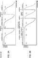
Fig. 2A is an illustrative diagram for illustrating an operation of the battery system of a related art.Fig. 2B is an illustrative diagram for illustrating an operation of the battery system shown inFig. 1 . -
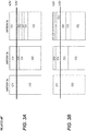
Fig. 3A is a time chart of the battery system of a related art.Fig. 3B is a time chart of the battery system shown inFig. 1 . -
Fig. 4 is a flow chart showing a charge processing procedure of a controller that constitutes the battery system shown inFig. 1 . - The teachings of the present disclosure will be described below with reference to the drawings.
- A battery system shown in
Fig. 1 is, for example, an apparatus that supplies power obtained by reusing a deteriorated battery. - As shown in
Fig. 1 , a battery system 1 includes a plurality ofbatteries 2a to 2c and abattery control unit 3. InFig. 1 , an example in which threebatteries 2a to 2c can be connected in series is described to simplify the description, but the present invention is not limited thereto. The number of thebatteries 2a to 2c may be plural, and may be two or four or more. Each of the plurality ofbatteries 2a to 2c is a chargeable and dischargeable storage battery, and may be configured with one cell or may be configured with a plurality of cells. - The
battery control unit 3 includes a plurality ofswitching units 4a to 4c, a plurality ofvoltage measurement units 5a to 5c, acontroller 6, and acharger 7. The plurality ofswitching units 4a to 4c are provided corresponding to the plurality ofbatteries 2a to 2c, respectively. The plurality ofswitching units 4a to 4c have the same configuration. - The
switching units 4a to 4c are provided so as to be switchable between a connected state wherecorresponding batteries 2a to 2c are connected in series withother batteries 2a to 2c and a non-connected state where thecorresponding batteries 2a to 2c are disconnected from series connection withother batteries 2a to 2c. Specifically, thebatteries 2a to 2c, switched to a connected state by theswitching units 4a to 4c, are connected in series and used as a power source. On the other hand, thebatteries 2a to 2c, switched to a non-connected state by theswitching units 4a to 4c, are disconnected from thebatteries 2a to 2c in a connected state and are not used as the power source. - The
switching unit 4a is configured with a first switch SW1a connected in series with thebattery 2a, and a second switch SW2a connected in parallel to the series arrangement comprising thebattery 2a and the first switch SW1a. One end T11 of the first switch SW1a is connected to one electrode (for example, a positive electrode) of thebattery 2a. One end T21 of the second switch SW2a is connected to the other electrode (for example, a negative electrode) of thebattery 2a, and the other end T22 of the second switch SW2a is connected to the other end T12 of the first switch SW1a. Theswitching units switching unit 4a with "b" and "c" respectively, and detailed description thereof will be omitted. - The other end T12 of a first switch SW1b is connected to a negative electrode of the
battery 2a, and the other end T12 of a first switch SWlc is connected to a negative electrode of thebattery 2b. That is, the first switch SW1b is connected between thebattery 2a and thebattery 2b that are adjacent to each other, and the first switch SWlc is connected between thebattery 2b and thebattery 2c that are adjacent to each other, respectively. - According to the above configuration, when the second switches SW2a to SW2c are turned off and the first switches SW1a to SW1c are turned on, the
corresponding batteries 2a to 2c are in a connected state. Further, when the first switches SW1a to SW1c are turned off, thecorresponding batteries 2a to 2c are in a non-connected state. At this time, when the second switches SW2a to SW2c are turned on, a bypass path is formed, and only the connectedbatteries 2a to 2c are connected in series. - The plurality of
voltage measurement units 5a to 5c measure both-end voltages of thecorresponding batteries 2a to 2c, and output measurement results thereof to thecontroller 6 to be described later. - The
controller 6 is configured with well-known CPU, ROM, and RAM, and controls the entire battery system 1. Thecontroller 6 controls on/off of the first switches SWla to SW1c and the second switches SW2a to SW2c based on the both-end voltages of thebatteries 2a to 2c. - The
charger 7 is connected to both ends of thebatteries 2a to 2c and charges thebatteries 2a to 2c. Thecharger 7 can be switched between the constant current charging and the constant voltage charging. Thecontroller 6 controls thecharger 7 to change between the constant current charging and the constant voltage charging. - Next, an outline of an operation of the battery system 1 described above will be described below with reference to
Figs. 2A and 2B , andFigs 3A and 3B . It is assumed that a capacity decreases in an order ofbattery 2c >battery 2b >battery 2a due to deterioration. Further, for example, the description will be made assuming that a discharge termination voltage = 4.2 V and a charge changing voltage for changing from the constant current charging to the constant voltage charging = 3.8 V (< discharge termination voltage). In the related art, as shown inFig. 2A andFig. 3A , first, thecontroller 6 switches thecharger 7 to the constant current charging (CC) and charges thebatteries 2a to 2c with a constant current. Thereafter, when thebattery 2a first reaches 3.8 V, thecontroller 6 switches thecharger 7 to the constant voltage charging (CV) and charges thebatteries 2a to 2c at a constant voltage. When thebattery 2a reaches 4.2 V, thecontroller 6 bypasses thebattery 2a by putting thebattery 2a in a non-connected state and changes thecharger 7 to the constant current charging. Accordingly, thebatteries battery 2b reaches 3.8 V, thecontroller 6 switches thecharger 7 to the constant voltage charging and charges thebatteries battery 2b reaches 4.2 V, thecontroller 6 bypasses thebattery 2b and switches thecharger 7 to the constant current charging. Accordingly, thebattery 2c is charged with a constant current. When thebattery 2c reaches 3.8 V, thecontroller 6 switches thecharger 7 to the constant voltage charging and charges thebattery 2c at a constant voltage. When thebattery 2c reaches 4.2 V, charging is terminated. - On the contrary, as shown in
Figs. 2B and3B , thecontroller 6 functions as a charging controller and switches thecharger 7 to the constant current charging (CC). Thebatteries 2a to 2c are charged with a constant current. Thereafter, when thebattery 2a first reaches 3.8 V, thecontroller 6 bypasses thebattery 2a and continues the constant current charging of thebatteries battery 2b reaches 3.8 V, thecontroller 6 bypasses thebattery 2b and continues the constant current charging of thebattery 2c. When thebattery 2c reaches 3.8 V, thecontroller 6 returns all thebatteries 2a to 2c to a connected state and changes thecharger 7 to the constant voltage charging. Accordingly, thebatteries 2a to 2c are charged at a constant voltage. Thereafter, thecontroller 6 bypasses thebatteries 2a to 2c when thebatteries 2a to 2c reaches 4.2 V. - As is clear from
Figs. 2A and 2B , in the related art, although thebatteries batteries 2a to 2c have not reached 3.8 V, the constant voltage charging is not performed, and a charging time can be shortened. - Next, the detailed operation of the battery system 1 described above will be described below with reference to
Fig. 4. Fig. 4 is a flowchart showing a charge processing procedure of thecontroller 6 shown inFig. 1 . - Upon receiving a charging command, the
controller 6 starts the charge processing shown inFig. 4 . First, thecontroller 6 turns off all the first switches SW1a to SW1C and all the second switches SW2a to SW2c (step S1). Thereafter, thecontroller 6 turns on all the first switches SW1a to SW1c (step S2) so as to connect all thebatteries 2a to 2c in series. Next, after switching thecharger 7 to the constant current charging (step S3), thecontroller 6 connects thecharger 7 to thebatteries 2a to 2c and starts the constant current charging (step S4). - Next, the
controller 6 acquires the both-end voltages of thebatteries 2a to 2c measured by thevoltage measurement units 5a to 5c, and compares the acquired both-end voltages with the charge changing voltage (3.8 V) (step S5). As a result of the comparison, thecontroller 6 returns to step S5 if there is nobattery 2a to 2c that has reached the charge changing voltage among theconnected batteries 2a to 2c (N in step S5). - On the contrary, as a result of the comparison, if there is a battery among the
batteries 2a to 2c that has reached the charge changing voltage (Y in step S5), thecontroller 6 determines whether all thebatteries 2a to 2c have reached the charge changing voltage (step S6). If all thebatteries 2a to 2c have not reached the charge changing voltage (N in step S6), thecontroller 6 bypasses thebatteries 2a to 2c determined to have reached the charge changing voltage in step S6 (step S7), and then returns to step S5. - If all the
batteries 2a to 2c have reached a charge changing voltage (Y in step S6), thecontroller 6 puts all thebatteries 2a to 2c in a connected state (step S8) and switches thecharger 7 to the constant voltage charging (step S9). - Next, the
controller 6 acquires the both-end voltages of thebatteries 2a to 2c measured by thevoltage measurement units 5a to 5c, and compares the acquired both-end voltages with the charge termination voltage (4.2 V) (step S10). As a result of the comparison, thecontroller 6 returns to step S10 if there is nobattery 2a to 2c that has reached the charge termination voltage among theconnected batteries 2a to 2c (N in step S10). - On the contrary, as a result of the comparison, if there is a battery among the
batteries 2a to 2c that has reached the charge termination voltage (Y in step S10), thecontroller 6 determines whether all thebatteries 2a to 2c have reached the charge termination voltage (step S11). If all thebatteries 2a to 2c have not reached the charge termination voltage (N in step S11), thecontroller 6 bypasses thebatteries 2a to 2c determined to have reached the charge termination voltage in step S10 (step S12), and then returns to step S10. - On the other hand, when determining that all the
batteries 2a to 2c have reached the discharge termination voltage (Y in step S11), thecontroller 6 disconnects thecharger 7 from thebatteries 2a to 2c so as to stop charging (step S13). Thereafter, thecontroller 6 turns off all the first switches SW1a to SW1c and all the second switches SW2a to SW2c (step S14), and then turns on all the first switches SW1a to SW1c (step S15) so as to terminate the processing. - The present invention is not limited to the embodiment described above, and modifications, improvements, or the like can be made as appropriate, as long as they are covered by the appended claims, which ultimately define the subject-matter protected by the present invention.
- According to the above description, although the
switching unit 4a is configured with the first switch SW1a and the second switch SW2a, theswitching unit 4b is configured with the first switch SW1b and the second switch SW2b, and theswitching unit 4c is configured with the first switch SW1c and the second switch SW2c, the present invention is not limited thereto. The switchingunits 4a to 4c may be configured with switching switches that select one of thebatteries 2a to 2c and a bypass circuit connected in parallel to thebatteries 2a to 2c.
Claims (2)
- A battery system comprising:a plurality of batteries (2a-2c);a plurality of switching units (4a-4c), each switching unit being configured to switch between a connected state in which a corresponding one of the plurality of batteries (2a-2c) is connected in series with other batteries of the plurality of batteries (2a-2c) and a non-connected state in which the battery is bypassed and disconnected from the other batteries;a charger (7) configured to charge the batteries of the plurality of batteries connected in series, the charger being switchable between a constant current charging mode and a constant voltage charging mode;a controller configured to control the plurality of switching units (4a-4c) and the charger (7);wherein the controller is configured to cause the charger (7) to charge the plurality of series connected batteries with a constant current, to determine whether one of the plurality of batteries has reached a charge changing voltage during the constant current charging, to cause the respective switching unit to bypass and disconnect the battery determined to have reached the charge changing voltage, to cause the plurality of switching units to connect all of the plurality of batteries in series when all of the plurality of batteries have reached the charge changing voltage, and to switch the charger (7) from the constant current charging mode to the constant voltage charging mode so as to charge the plurality of series connected batteries at a constant voltage,characterized in thatthe controller is further configured to perform operations comprising determining whether one of the plurality of series connected batteries has reached a charge termination voltage during constant voltage charging, and causing the respective switching unit to bypass and disconnect the battery determined to have reached the charge termination voltage, the operations being repeated until all of the plurality of batteries are determined to have reached the charge termination voltage.
- The battery system according to claim 1,wherein each of the plurality of switching units (4a-4c) includes a first switch (SW1a-SW1c) and a second switch (SW2a-SW2c),wherein the first switch is connected in series with the corresponding one of the plurality of batteries (2a-2c), andwherein the second switch is connected in parallel to the series arrangement comprising the corresponding one of the pluralityof batteries (2a-2c) and the first switch.
Applications Claiming Priority (1)
| Application Number | Priority Date | Filing Date | Title |
|---|---|---|---|
| JP2019179431A JP7051776B2 (en) | 2019-09-30 | 2019-09-30 | Battery control unit and battery system |
Publications (2)
| Publication Number | Publication Date |
|---|---|
| EP3799251A1 EP3799251A1 (en) | 2021-03-31 |
| EP3799251B1 true EP3799251B1 (en) | 2021-12-01 |
Family
ID=72659621
Family Applications (1)
| Application Number | Title | Priority Date | Filing Date |
|---|---|---|---|
| EP20198375.6A Active EP3799251B1 (en) | 2019-09-30 | 2020-09-25 | Battery control unit and battery system |
Country Status (4)
| Country | Link |
|---|---|
| US (1) | US11616374B2 (en) |
| EP (1) | EP3799251B1 (en) |
| JP (1) | JP7051776B2 (en) |
| CN (1) | CN112583067A (en) |
Families Citing this family (12)
| Publication number | Priority date | Publication date | Assignee | Title |
|---|---|---|---|---|
| WO2019060665A1 (en) * | 2017-09-22 | 2019-03-28 | Urban Electric Power Inc. | A system to charge cells assembled into a battery |
| US20210249981A1 (en) | 2018-09-05 | 2021-08-12 | Dpm Technologies Inc. | Systems and methods for intelligent control of rotating electric machines |
| JP7096193B2 (en) * | 2019-04-04 | 2022-07-05 | 矢崎総業株式会社 | Battery control unit and battery system |
| US11722026B2 (en) | 2019-04-23 | 2023-08-08 | Dpm Technologies Inc. | Fault tolerant rotating electric machine |
| JP7100002B2 (en) * | 2019-09-10 | 2022-07-12 | 矢崎総業株式会社 | Battery control unit and battery system |
| US11897362B2 (en) * | 2021-05-04 | 2024-02-13 | Exro Technologies Inc. | Systems and methods for individual control of a plurality of controllable units of battery cells |
| CN117337545A (en) | 2021-05-13 | 2024-01-02 | Exro技术公司 | Method and device for driving coils of polyphase motors |
| KR20240046176A (en) | 2021-07-08 | 2024-04-08 | 엑스로 테크놀로지스 아이엔씨. | Dynamically reconfigurable power converter using windings of an electric machine |
| CA3170801A1 (en) * | 2021-08-19 | 2023-02-19 | Neutron Automotive Controls Inc. | Battery cell balancing circuit system and method |
| JP7744880B2 (en) * | 2022-06-27 | 2025-09-26 | 矢崎総業株式会社 | Battery connection module and energy storage system |
| CN120389492B (en) * | 2025-06-27 | 2025-11-18 | 广东旭派新能源有限公司 | System and method for realizing multi-battery module charging management |
| CN120955861A (en) * | 2025-10-13 | 2025-11-14 | 宁德时代新能源科技股份有限公司 | Battery systems, battery management systems, electrical devices and energy storage devices |
Family Cites Families (52)
| Publication number | Priority date | Publication date | Assignee | Title |
|---|---|---|---|---|
| JPH07235332A (en) * | 1994-02-24 | 1995-09-05 | Sanyo Electric Co Ltd | Secondary battery charging method |
| US5747968A (en) * | 1996-01-11 | 1998-05-05 | Lockheed Martin Corp. Missiles & Space | Lithium polymer battery charger apparatus |
| US5666040A (en) * | 1996-08-27 | 1997-09-09 | Bourbeau; Frank | Networked battery monitor and control system and charging method |
| US5889385A (en) * | 1997-08-19 | 1999-03-30 | Advanced Charger Technology, Inc. | Equalization of series-connected cells of a battery using controlled charging and discharging pulses |
| US5952815A (en) * | 1997-07-25 | 1999-09-14 | Minnesota Mining & Manufacturing Co. | Equalizer system and method for series connected energy storing devices |
| US7557538B2 (en) * | 2001-09-03 | 2009-07-07 | Gpe International Limited | Intelligent serial battery charger |
| US7081737B2 (en) * | 2003-06-19 | 2006-07-25 | O2Micro International Limited | Battery cell monitoring and balancing circuit |
| JP3832660B2 (en) * | 2003-10-29 | 2006-10-11 | 株式会社Nttファシリティーズ | Charger |
| JP3904579B2 (en) * | 2004-12-03 | 2007-04-11 | ローム株式会社 | Power supply device, light emitting device using the same, and electronic device |
| KR20100033509A (en) * | 2007-06-08 | 2010-03-30 | 파나소닉 주식회사 | Power system and assembled battery controlling method |
| TW200913433A (en) * | 2007-09-10 | 2009-03-16 | J Tek Inc | Scattered energy storage control system |
| JP2009247195A (en) * | 2008-03-31 | 2009-10-22 | O2 Micro Inc | Battery management system with adjustable charging current |
| US20090251100A1 (en) * | 2008-04-02 | 2009-10-08 | Pratt & Whitney Rocketdyne, Inc. | Stackable battery module |
| JP5289083B2 (en) * | 2009-02-05 | 2013-09-11 | 三洋電機株式会社 | Secondary battery abnormality detection device and secondary battery device |
| JP5439000B2 (en) * | 2009-03-19 | 2014-03-12 | 株式会社東芝 | Battery assembly system and battery protection device |
| WO2010109956A1 (en) * | 2009-03-27 | 2010-09-30 | 株式会社日立製作所 | Electric storage device |
| CN102648104B (en) * | 2009-11-17 | 2015-04-22 | 丰田自动车株式会社 | Vehicle and method for controlling vehicle |
| JP5438542B2 (en) * | 2010-02-15 | 2014-03-12 | 矢崎総業株式会社 | Voltage detector |
| JP5567956B2 (en) * | 2010-09-16 | 2014-08-06 | 矢崎総業株式会社 | Cell voltage equalization device for multiple assembled batteries |
| US8470464B2 (en) * | 2010-10-14 | 2013-06-25 | Alliant Techsystems Inc. | Methods and apparatuses for electrochemical cell monitoring and control |
| JP2012249345A (en) * | 2011-05-25 | 2012-12-13 | Nippon Telegr & Teleph Corp <Ntt> | Charging system, charging method, and power supply system |
| US8816639B2 (en) * | 2011-06-02 | 2014-08-26 | Aerojet Rocketdyne Of De, Inc. | Charge balancing topology |
| WO2013001683A1 (en) * | 2011-06-28 | 2013-01-03 | パナソニック株式会社 | Multiplexer for voltage measurement and voltage meter comprising same |
| JP6124346B2 (en) * | 2011-07-08 | 2017-05-10 | Necエナジーデバイス株式会社 | Charging control system, battery pack and charging method |
| JP2013031249A (en) * | 2011-07-27 | 2013-02-07 | Mitsubishi Motors Corp | Battery device charging system |
| KR101526641B1 (en) * | 2011-12-08 | 2015-06-08 | 현대자동차주식회사 | Degradation estimation method for high voltage battery of vehicle |
| TWI466408B (en) * | 2012-01-20 | 2014-12-21 | 威盛電子股份有限公司 | Rechargeable battery module and charging battery module charging method |
| US9525289B2 (en) * | 2012-02-29 | 2016-12-20 | Nec Energy Devices, Ltd. | Battery control system and battery pack |
| WO2013161512A1 (en) * | 2012-04-24 | 2013-10-31 | Necエナジーデバイス株式会社 | Charge control apparatus and charge control method |
| JP5981777B2 (en) * | 2012-06-12 | 2016-08-31 | 旭化成株式会社 | Charging system and charging method |
| JP5605401B2 (en) * | 2012-07-20 | 2014-10-15 | トヨタ自動車株式会社 | Power storage system and control method |
| US9520613B2 (en) * | 2013-07-23 | 2016-12-13 | Infineon Technologies Ag | Battery control with block selection |
| US10300806B2 (en) * | 2013-10-09 | 2019-05-28 | Ford Global Technologies, Llc | Vehicle and method for controlling a battery in a vehicle |
| CN106611888B (en) * | 2015-10-22 | 2019-01-11 | 松下知识产权经营株式会社 | The control method of accumulating system and accumulating system |
| US10014716B2 (en) * | 2015-12-22 | 2018-07-03 | Robert Bosch Gmbh | Discrete energy reservoir with diagnostics |
| JP6883396B2 (en) * | 2016-08-25 | 2021-06-09 | 矢崎総業株式会社 | Quick charging device |
| US10250045B2 (en) * | 2017-01-05 | 2019-04-02 | Gbatteries Energy Canada Inc. | System and method for battery pack |
| US10879707B2 (en) * | 2017-10-16 | 2020-12-29 | Ardent Edge, LLC | Isolated communication system |
| US11081899B2 (en) * | 2018-07-19 | 2021-08-03 | Yazaki Corporation | Battery system |
| US11462918B2 (en) * | 2019-02-22 | 2022-10-04 | Aurora Flight Sciences Corporation | Battery switch with current control |
| JP7096193B2 (en) * | 2019-04-04 | 2022-07-05 | 矢崎総業株式会社 | Battery control unit and battery system |
| JP6970136B2 (en) * | 2019-04-04 | 2021-11-24 | 矢崎総業株式会社 | Battery control unit and battery system |
| JP7100002B2 (en) * | 2019-09-10 | 2022-07-12 | 矢崎総業株式会社 | Battery control unit and battery system |
| JP7144466B2 (en) * | 2020-01-28 | 2022-09-29 | 矢崎総業株式会社 | Battery control unit and battery system |
| TWI701889B (en) * | 2020-02-27 | 2020-08-11 | 天揚精密科技股份有限公司 | Charging balance device, system and method for a multicell battery pack |
| KR102120797B1 (en) * | 2020-03-23 | 2020-06-09 | (주)그린파워 | Battery charging-discharging apparatus and method |
| JP7157101B2 (en) * | 2020-06-19 | 2022-10-19 | 矢崎総業株式会社 | Battery control unit and battery system |
| JP7160862B2 (en) * | 2020-06-19 | 2022-10-25 | 矢崎総業株式会社 | Battery control unit and battery system |
| JP7220960B2 (en) * | 2020-08-04 | 2023-02-13 | 矢崎総業株式会社 | Charge/discharge control device, battery system, and charge/discharge control method |
| CN114079310B (en) * | 2020-08-19 | 2025-02-11 | 矢崎总业株式会社 | Battery control device and battery system |
| JP7136855B2 (en) * | 2020-08-19 | 2022-09-13 | 矢崎総業株式会社 | Power supply control device, power supply system, power supply control method, and program |
| JP7189182B2 (en) * | 2020-09-07 | 2022-12-13 | 矢崎総業株式会社 | Charging control device, battery system, and charging control method |
-
2019
- 2019-09-30 JP JP2019179431A patent/JP7051776B2/en active Active
-
2020
- 2020-09-25 EP EP20198375.6A patent/EP3799251B1/en active Active
- 2020-09-29 US US17/035,715 patent/US11616374B2/en active Active
- 2020-09-30 CN CN202011055944.0A patent/CN112583067A/en active Pending
Also Published As
| Publication number | Publication date |
|---|---|
| US20210098996A1 (en) | 2021-04-01 |
| JP2021057988A (en) | 2021-04-08 |
| JP7051776B2 (en) | 2022-04-11 |
| CN112583067A (en) | 2021-03-30 |
| EP3799251A1 (en) | 2021-03-31 |
| US11616374B2 (en) | 2023-03-28 |
Similar Documents
| Publication | Publication Date | Title |
|---|---|---|
| EP3799251B1 (en) | Battery control unit and battery system | |
| EP3793057B1 (en) | Battery control unit and battery system | |
| EP3859936B1 (en) | Battery control unit and battery system | |
| JP3389670B2 (en) | Series connection circuit of secondary battery | |
| US11843267B2 (en) | Battery control unit and battery system | |
| US12034323B2 (en) | Battery control unit and battery system | |
| US11081899B2 (en) | Battery system | |
| JP6970136B2 (en) | Battery control unit and battery system | |
| CN111799852B (en) | Battery control unit and battery system | |
| EP3965254B1 (en) | Charging control device, battery system and charging control method | |
| CN110854944A (en) | Charging control apparatus and method | |
| CN108432085B (en) | Balanced Battery Charging System | |
| JP2004229391A (en) | Battery pack | |
| JP2000228831A (en) | How to compensate for battery variations | |
| JP2007250364A (en) | Secondary battery internal charging device and charging method |
Legal Events
| Date | Code | Title | Description |
|---|---|---|---|
| PUAI | Public reference made under article 153(3) epc to a published international application that has entered the european phase |
Free format text: ORIGINAL CODE: 0009012 |
|
| STAA | Information on the status of an ep patent application or granted ep patent |
Free format text: STATUS: REQUEST FOR EXAMINATION WAS MADE |
|
| 17P | Request for examination filed |
Effective date: 20200925 |
|
| AK | Designated contracting states |
Kind code of ref document: A1 Designated state(s): AL AT BE BG CH CY CZ DE DK EE ES FI FR GB GR HR HU IE IS IT LI LT LU LV MC MK MT NL NO PL PT RO RS SE SI SK SM TR |
|
| AX | Request for extension of the european patent |
Extension state: BA ME |
|
| RIC1 | Information provided on ipc code assigned before grant |
Ipc: H01M 10/42 20060101ALN20210805BHEP Ipc: H01M 10/44 20060101ALI20210805BHEP Ipc: H02J 7/00 20060101AFI20210805BHEP |
|
| GRAP | Despatch of communication of intention to grant a patent |
Free format text: ORIGINAL CODE: EPIDOSNIGR1 |
|
| STAA | Information on the status of an ep patent application or granted ep patent |
Free format text: STATUS: GRANT OF PATENT IS INTENDED |
|
| INTG | Intention to grant announced |
Effective date: 20210920 |
|
| GRAS | Grant fee paid |
Free format text: ORIGINAL CODE: EPIDOSNIGR3 |
|
| GRAA | (expected) grant |
Free format text: ORIGINAL CODE: 0009210 |
|
| STAA | Information on the status of an ep patent application or granted ep patent |
Free format text: STATUS: THE PATENT HAS BEEN GRANTED |
|
| AK | Designated contracting states |
Kind code of ref document: B1 Designated state(s): AL AT BE BG CH CY CZ DE DK EE ES FI FR GB GR HR HU IE IS IT LI LT LU LV MC MK MT NL NO PL PT RO RS SE SI SK SM TR |
|
| REG | Reference to a national code |
Ref country code: GB Ref legal event code: FG4D |
|
| REG | Reference to a national code |
Ref country code: AT Ref legal event code: REF Ref document number: 1452709 Country of ref document: AT Kind code of ref document: T Effective date: 20211215 Ref country code: CH Ref legal event code: EP |
|
| REG | Reference to a national code |
Ref country code: IE Ref legal event code: FG4D |
|
| REG | Reference to a national code |
Ref country code: DE Ref legal event code: R096 Ref document number: 602020001163 Country of ref document: DE |
|
| REG | Reference to a national code |
Ref country code: LT Ref legal event code: MG9D |
|
| REG | Reference to a national code |
Ref country code: NL Ref legal event code: MP Effective date: 20211201 |
|
| REG | Reference to a national code |
Ref country code: AT Ref legal event code: MK05 Ref document number: 1452709 Country of ref document: AT Kind code of ref document: T Effective date: 20211201 |
|
| PG25 | Lapsed in a contracting state [announced via postgrant information from national office to epo] |
Ref country code: RS Free format text: LAPSE BECAUSE OF FAILURE TO SUBMIT A TRANSLATION OF THE DESCRIPTION OR TO PAY THE FEE WITHIN THE PRESCRIBED TIME-LIMIT Effective date: 20211201 Ref country code: LT Free format text: LAPSE BECAUSE OF FAILURE TO SUBMIT A TRANSLATION OF THE DESCRIPTION OR TO PAY THE FEE WITHIN THE PRESCRIBED TIME-LIMIT Effective date: 20211201 Ref country code: FI Free format text: LAPSE BECAUSE OF FAILURE TO SUBMIT A TRANSLATION OF THE DESCRIPTION OR TO PAY THE FEE WITHIN THE PRESCRIBED TIME-LIMIT Effective date: 20211201 Ref country code: BG Free format text: LAPSE BECAUSE OF FAILURE TO SUBMIT A TRANSLATION OF THE DESCRIPTION OR TO PAY THE FEE WITHIN THE PRESCRIBED TIME-LIMIT Effective date: 20220301 Ref country code: AT Free format text: LAPSE BECAUSE OF FAILURE TO SUBMIT A TRANSLATION OF THE DESCRIPTION OR TO PAY THE FEE WITHIN THE PRESCRIBED TIME-LIMIT Effective date: 20211201 |
|
| PG25 | Lapsed in a contracting state [announced via postgrant information from national office to epo] |
Ref country code: SE Free format text: LAPSE BECAUSE OF FAILURE TO SUBMIT A TRANSLATION OF THE DESCRIPTION OR TO PAY THE FEE WITHIN THE PRESCRIBED TIME-LIMIT Effective date: 20211201 Ref country code: PL Free format text: LAPSE BECAUSE OF FAILURE TO SUBMIT A TRANSLATION OF THE DESCRIPTION OR TO PAY THE FEE WITHIN THE PRESCRIBED TIME-LIMIT Effective date: 20211201 Ref country code: NO Free format text: LAPSE BECAUSE OF FAILURE TO SUBMIT A TRANSLATION OF THE DESCRIPTION OR TO PAY THE FEE WITHIN THE PRESCRIBED TIME-LIMIT Effective date: 20220301 Ref country code: LV Free format text: LAPSE BECAUSE OF FAILURE TO SUBMIT A TRANSLATION OF THE DESCRIPTION OR TO PAY THE FEE WITHIN THE PRESCRIBED TIME-LIMIT Effective date: 20211201 Ref country code: HR Free format text: LAPSE BECAUSE OF FAILURE TO SUBMIT A TRANSLATION OF THE DESCRIPTION OR TO PAY THE FEE WITHIN THE PRESCRIBED TIME-LIMIT Effective date: 20211201 Ref country code: GR Free format text: LAPSE BECAUSE OF FAILURE TO SUBMIT A TRANSLATION OF THE DESCRIPTION OR TO PAY THE FEE WITHIN THE PRESCRIBED TIME-LIMIT Effective date: 20220302 |
|
| PG25 | Lapsed in a contracting state [announced via postgrant information from national office to epo] |
Ref country code: NL Free format text: LAPSE BECAUSE OF FAILURE TO SUBMIT A TRANSLATION OF THE DESCRIPTION OR TO PAY THE FEE WITHIN THE PRESCRIBED TIME-LIMIT Effective date: 20211201 |
|
| PG25 | Lapsed in a contracting state [announced via postgrant information from national office to epo] |
Ref country code: SM Free format text: LAPSE BECAUSE OF FAILURE TO SUBMIT A TRANSLATION OF THE DESCRIPTION OR TO PAY THE FEE WITHIN THE PRESCRIBED TIME-LIMIT Effective date: 20211201 Ref country code: SK Free format text: LAPSE BECAUSE OF FAILURE TO SUBMIT A TRANSLATION OF THE DESCRIPTION OR TO PAY THE FEE WITHIN THE PRESCRIBED TIME-LIMIT Effective date: 20211201 Ref country code: RO Free format text: LAPSE BECAUSE OF FAILURE TO SUBMIT A TRANSLATION OF THE DESCRIPTION OR TO PAY THE FEE WITHIN THE PRESCRIBED TIME-LIMIT Effective date: 20211201 Ref country code: PT Free format text: LAPSE BECAUSE OF FAILURE TO SUBMIT A TRANSLATION OF THE DESCRIPTION OR TO PAY THE FEE WITHIN THE PRESCRIBED TIME-LIMIT Effective date: 20220401 Ref country code: ES Free format text: LAPSE BECAUSE OF FAILURE TO SUBMIT A TRANSLATION OF THE DESCRIPTION OR TO PAY THE FEE WITHIN THE PRESCRIBED TIME-LIMIT Effective date: 20211201 Ref country code: EE Free format text: LAPSE BECAUSE OF FAILURE TO SUBMIT A TRANSLATION OF THE DESCRIPTION OR TO PAY THE FEE WITHIN THE PRESCRIBED TIME-LIMIT Effective date: 20211201 Ref country code: CZ Free format text: LAPSE BECAUSE OF FAILURE TO SUBMIT A TRANSLATION OF THE DESCRIPTION OR TO PAY THE FEE WITHIN THE PRESCRIBED TIME-LIMIT Effective date: 20211201 |
|
| REG | Reference to a national code |
Ref country code: DE Ref legal event code: R097 Ref document number: 602020001163 Country of ref document: DE |
|
| PG25 | Lapsed in a contracting state [announced via postgrant information from national office to epo] |
Ref country code: IS Free format text: LAPSE BECAUSE OF FAILURE TO SUBMIT A TRANSLATION OF THE DESCRIPTION OR TO PAY THE FEE WITHIN THE PRESCRIBED TIME-LIMIT Effective date: 20220401 |
|
| PLBE | No opposition filed within time limit |
Free format text: ORIGINAL CODE: 0009261 |
|
| STAA | Information on the status of an ep patent application or granted ep patent |
Free format text: STATUS: NO OPPOSITION FILED WITHIN TIME LIMIT |
|
| PG25 | Lapsed in a contracting state [announced via postgrant information from national office to epo] |
Ref country code: DK Free format text: LAPSE BECAUSE OF FAILURE TO SUBMIT A TRANSLATION OF THE DESCRIPTION OR TO PAY THE FEE WITHIN THE PRESCRIBED TIME-LIMIT Effective date: 20211201 Ref country code: AL Free format text: LAPSE BECAUSE OF FAILURE TO SUBMIT A TRANSLATION OF THE DESCRIPTION OR TO PAY THE FEE WITHIN THE PRESCRIBED TIME-LIMIT Effective date: 20211201 |
|
| 26N | No opposition filed |
Effective date: 20220902 |
|
| PG25 | Lapsed in a contracting state [announced via postgrant information from national office to epo] |
Ref country code: MC Free format text: LAPSE BECAUSE OF FAILURE TO SUBMIT A TRANSLATION OF THE DESCRIPTION OR TO PAY THE FEE WITHIN THE PRESCRIBED TIME-LIMIT Effective date: 20211201 |
|
| REG | Reference to a national code |
Ref country code: BE Ref legal event code: MM Effective date: 20220930 |
|
| PG25 | Lapsed in a contracting state [announced via postgrant information from national office to epo] |
Ref country code: IT Free format text: LAPSE BECAUSE OF FAILURE TO SUBMIT A TRANSLATION OF THE DESCRIPTION OR TO PAY THE FEE WITHIN THE PRESCRIBED TIME-LIMIT Effective date: 20211201 |
|
| PG25 | Lapsed in a contracting state [announced via postgrant information from national office to epo] |
Ref country code: LU Free format text: LAPSE BECAUSE OF NON-PAYMENT OF DUE FEES Effective date: 20220925 |
|
| PG25 | Lapsed in a contracting state [announced via postgrant information from national office to epo] |
Ref country code: IE Free format text: LAPSE BECAUSE OF NON-PAYMENT OF DUE FEES Effective date: 20220925 Ref country code: FR Free format text: LAPSE BECAUSE OF NON-PAYMENT OF DUE FEES Effective date: 20220930 |
|
| PG25 | Lapsed in a contracting state [announced via postgrant information from national office to epo] |
Ref country code: BE Free format text: LAPSE BECAUSE OF NON-PAYMENT OF DUE FEES Effective date: 20220930 |
|
| PG25 | Lapsed in a contracting state [announced via postgrant information from national office to epo] |
Ref country code: CY Free format text: LAPSE BECAUSE OF FAILURE TO SUBMIT A TRANSLATION OF THE DESCRIPTION OR TO PAY THE FEE WITHIN THE PRESCRIBED TIME-LIMIT Effective date: 20211201 |
|
| REG | Reference to a national code |
Ref country code: CH Ref legal event code: PL |
|
| PG25 | Lapsed in a contracting state [announced via postgrant information from national office to epo] |
Ref country code: MK Free format text: LAPSE BECAUSE OF FAILURE TO SUBMIT A TRANSLATION OF THE DESCRIPTION OR TO PAY THE FEE WITHIN THE PRESCRIBED TIME-LIMIT Effective date: 20211201 |
|
| PG25 | Lapsed in a contracting state [announced via postgrant information from national office to epo] |
Ref country code: TR Free format text: LAPSE BECAUSE OF FAILURE TO SUBMIT A TRANSLATION OF THE DESCRIPTION OR TO PAY THE FEE WITHIN THE PRESCRIBED TIME-LIMIT Effective date: 20211201 |
|
| PG25 | Lapsed in a contracting state [announced via postgrant information from national office to epo] |
Ref country code: CH Free format text: LAPSE BECAUSE OF NON-PAYMENT OF DUE FEES Effective date: 20230930 |
|
| PG25 | Lapsed in a contracting state [announced via postgrant information from national office to epo] |
Ref country code: HU Free format text: LAPSE BECAUSE OF FAILURE TO SUBMIT A TRANSLATION OF THE DESCRIPTION OR TO PAY THE FEE WITHIN THE PRESCRIBED TIME-LIMIT; INVALID AB INITIO Effective date: 20200925 Ref country code: CH Free format text: LAPSE BECAUSE OF NON-PAYMENT OF DUE FEES Effective date: 20230930 |
|
| PG25 | Lapsed in a contracting state [announced via postgrant information from national office to epo] |
Ref country code: MT Free format text: LAPSE BECAUSE OF FAILURE TO SUBMIT A TRANSLATION OF THE DESCRIPTION OR TO PAY THE FEE WITHIN THE PRESCRIBED TIME-LIMIT Effective date: 20211201 |
|
| GBPC | Gb: european patent ceased through non-payment of renewal fee |
Effective date: 20240925 |
|
| PG25 | Lapsed in a contracting state [announced via postgrant information from national office to epo] |
Ref country code: GB Free format text: LAPSE BECAUSE OF NON-PAYMENT OF DUE FEES Effective date: 20240925 |
|
| PGFP | Annual fee paid to national office [announced via postgrant information from national office to epo] |
Ref country code: DE Payment date: 20250730 Year of fee payment: 6 |
|
| PG25 | Lapsed in a contracting state [announced via postgrant information from national office to epo] |
Ref country code: SI Free format text: LAPSE BECAUSE OF FAILURE TO SUBMIT A TRANSLATION OF THE DESCRIPTION OR TO PAY THE FEE WITHIN THE PRESCRIBED TIME-LIMIT Effective date: 20211201 |