EP3799107A1 - Time-of-flight mass spectrometer - Google Patents
Time-of-flight mass spectrometer Download PDFInfo
- Publication number
- EP3799107A1 EP3799107A1 EP18919667.8A EP18919667A EP3799107A1 EP 3799107 A1 EP3799107 A1 EP 3799107A1 EP 18919667 A EP18919667 A EP 18919667A EP 3799107 A1 EP3799107 A1 EP 3799107A1
- Authority
- EP
- European Patent Office
- Prior art keywords
- vacuum chamber
- temperature
- flight
- mass spectrometry
- time
- Prior art date
- Legal status (The legal status is an assumption and is not a legal conclusion. Google has not performed a legal analysis and makes no representation as to the accuracy of the status listed.)
- Granted
Links
Images

Classifications
-
- H—ELECTRICITY
- H01—ELECTRIC ELEMENTS
- H01J—ELECTRIC DISCHARGE TUBES OR DISCHARGE LAMPS
- H01J49/00—Particle spectrometers or separator tubes
- H01J49/26—Mass spectrometers or separator tubes
- H01J49/34—Dynamic spectrometers
- H01J49/40—Time-of-flight spectrometers
- H01J49/401—Time-of-flight spectrometers characterised by orthogonal acceleration, e.g. focusing or selecting the ions, pusher electrode
-
- H—ELECTRICITY
- H01—ELECTRIC ELEMENTS
- H01J—ELECTRIC DISCHARGE TUBES OR DISCHARGE LAMPS
- H01J49/00—Particle spectrometers or separator tubes
- H01J49/02—Details
- H01J49/06—Electron- or ion-optical arrangements
- H01J49/068—Mounting, supporting, spacing, or insulating electrodes
-
- H—ELECTRICITY
- H01—ELECTRIC ELEMENTS
- H01J—ELECTRIC DISCHARGE TUBES OR DISCHARGE LAMPS
- H01J49/00—Particle spectrometers or separator tubes
- H01J49/02—Details
-
- H—ELECTRICITY
- H01—ELECTRIC ELEMENTS
- H01J—ELECTRIC DISCHARGE TUBES OR DISCHARGE LAMPS
- H01J49/00—Particle spectrometers or separator tubes
- H01J49/02—Details
- H01J49/04—Arrangements for introducing or extracting samples to be analysed, e.g. vacuum locks; Arrangements for external adjustment of electron- or ion-optical components
- H01J49/0409—Sample holders or containers
-
- H—ELECTRICITY
- H01—ELECTRIC ELEMENTS
- H01J—ELECTRIC DISCHARGE TUBES OR DISCHARGE LAMPS
- H01J49/00—Particle spectrometers or separator tubes
- H01J49/02—Details
- H01J49/04—Arrangements for introducing or extracting samples to be analysed, e.g. vacuum locks; Arrangements for external adjustment of electron- or ion-optical components
- H01J49/0468—Arrangements for introducing or extracting samples to be analysed, e.g. vacuum locks; Arrangements for external adjustment of electron- or ion-optical components with means for heating or cooling the sample
- H01J49/0486—Arrangements for introducing or extracting samples to be analysed, e.g. vacuum locks; Arrangements for external adjustment of electron- or ion-optical components with means for heating or cooling the sample with means for monitoring the sample temperature
-
- H—ELECTRICITY
- H01—ELECTRIC ELEMENTS
- H01J—ELECTRIC DISCHARGE TUBES OR DISCHARGE LAMPS
- H01J49/00—Particle spectrometers or separator tubes
- H01J49/26—Mass spectrometers or separator tubes
- H01J49/34—Dynamic spectrometers
- H01J49/40—Time-of-flight spectrometers
Definitions
- the present invention relates to a time-of-flight mass spectrometry device.
- a time-of-flight mass spectrometry device (hereinafter, also referred to as TOFMS)
- TOFMS time-of-flight mass spectrometry device
- a certain kinetic energy is applied to ions to be analyzed, and the ions are introduced into a flight space being formed in a flight tube to fly in the flight space.
- the time required for each ion to fly a certain distance is measured, and the mass-to-charge ratio (m/z) of each ion is calculated based on the time of flight. Therefore, if the flight tube expands or contracts due to temperature change, the flight distance of the ions changes, and the flight time also changes, causing an error in the measured value of the mass-to-charge ratio.
- Patent Literature 1 PTL 1
- An ion source such as an electrospray ionization source (ESI) using a heated gas is used for the time-of-flight mass spectrometry device.
- a capillary or an orifice which is a vacuum partition for introducing ions generated by the ion source into a vacuum, is often heated for the purpose of promoting desolvation.
- the ion source and the capillary or orifice of the vacuum partition serve as heat sources. The heat generated in such a heat source is conducted through a structure that constitutes an ion path from the heat source to the flight tube, and is transmitted to the flight tube.
- the heat generation state of the ion source and the heating capillary fluctuates depending on operating conditions such as temperature conditions set according to the measurement conditions. Therefore, the temperature change of the flight tube due to the temperature change of the ion source and the heating capillary cannot be completely prevented and there was a problem that the expansion and contraction of the flight tube cannot be completely prevented only by installing the flight tube in the thermostatic chamber.
- an ambient temperature change of the device propagates through the heat conduction path via the device housing to the flight tube and causes the temperature change of the flight tube. Because this temperature change is conducted to the flight tube through a support member or the like that supports the flight tube in a vacuum chamber, even if the flight tube is placed in the thermostatic chamber, the temperature change of the flight tube due to the ambient temperature change of the device cannot be completely avoided, and there was a problem that the expansion and contraction of the flight tube cannot be completely prevented.
- various power supplies that can serve as heat sources are arranged in the device housing, and some power supplies are sometimes in direct contact with the vacuum chamber.
- the heat derived from such power supplies propagates through the structure that constitutes the path from the power supplies to the flight tube and is transmitted to the flight tube.
- the amount of heat generated by the power supply varies depending on operating conditions such as analysis conditions. Therefore, simply installing the flight tube in the thermostatic chamber cannot completely prevent the temperature change of the flight tube due to the change in the heat generation amount of the power supply, and thus, there was a problem that it is impossible to completely prevent the expansion and contraction of the flight tube.
- a time-of-flight mass spectrometry device comprises: an ion introduction unit; a vacuum chamber connected to the ion introduction unit; a support member provided inside the vacuum chamber; a flight tube having a part of the outer surface supported by the support member and provided inside the vacuum chamber; a temperature sensor provided in the vicinity of a connection portion with the support member of the vacuum chamber; a temperature adjustment element provided in the vicinity of the connection portion; and a temperature control unit that controls the temperature adjustment element based on a measurement result of the temperature sensor.
- the time-of-flight mass spectrometry device is in the time-of-flight mass spectrometry device according to the 1st aspect, and it is preferable that the time-of-flight mass spectrometry device comprises a plurality of the support members, wherein: the temperature sensor and the temperature adjustment element are provided in the vicinity of a plurality of the connection portions connected to the support members in the vacuum chamber.
- the time-of-flight mass spectrometry device is in the time-of-flight mass spectrometry device according to the 2nd aspect, and it is preferable that a plurality of the support members are arranged on a plane orthogonal to the longitudinal direction of the flight tube or in the vicinity of the plane.
- the time-of-flight mass spectrometry device is in the time-of-flight mass spectrometry device according to the 3rd aspect, and it is preferable that the time-of-flight mass spectrometry device further comprises: a second temperature sensor and a second temperature adjustment element provided on the outer surface of the vacuum chamber and at positions separated at least in the longitudinal direction of the flight tube from the temperature sensor, wherein: the temperature control unit controls the second temperature adjustment element based on a measurement result of the second temperature sensor.
- the time-of-flight mass spectrometry device is in the time-of-flight mass spectrometry device according to the 4th aspect, and it is preferable that the time-of-flight mass spectrometry device further comprises: a third temperature sensor and a third temperature adjustment element provided on the outer surface of the vacuum chamber and at positions separated at least in the longitudinal direction of the flight tube from the second temperature sensor, wherein the temperature control unit controls the third temperature adjustment element based on a measurement result of the third temperature sensor.
- the time-of-flight mass spectrometry device is in the time-of-flight mass spectrometry device according to any one of the 1st to 5th aspect, and it is preferable that an inner wall surface of the vacuum chamber facing the flight tube is subjected to radiation factor improvement treatment.
- the time-of-flight mass spectrometry device is in the time-of-flight mass spectrometry device according to the 6th aspect, and it is preferable that the ion introduction unit has a contact portion with a device housing, and the ion introduction unit is in thermal contact with the device housing via a high thermal conductive member at at least a part of the contact portion.
- the time-of-flight mass spectrometry device is in the time-of-flight mass spectrometry device according to any one of the 1st to 5th aspect, and it is preferable that the ion introduction unit has a contact portion with a device housing, and the ion introduction unit is in thermal contact with the device housing via a high thermal conductive member at at least a part of the contact portion.
- the time-of-flight mass spectrometry device is in the time-of-flight mass spectrometry device according to the 8th aspect, and it is preferable that the contact portions are a plurality of locations having different distances from the flight tube, and the high thermal conductive member is provided on a contact portion among a plurality of the contact portions that is far from the flight tube.
- the time-of-flight mass spectrometry device is in the time-of-flight mass spectrometry device according to any one of the 1st to 5th aspect, and it is preferable that the vacuum chamber has a second contact portion that contacts with the device housing, and the vacuum chamber is in thermal contact with a device housing via a low heat conductive member at at least a part of the second contact portion.
- the time-of-flight mass spectrometry device is in the time-of-flight mass spectrometry device according to the 6th aspect, and it is preferable that the vacuum chamber has a second contact portion that contacts with the device housing, and the vacuum chamber is in thermal contact with a device housing via a low heat conductive member at at least a part of the second contact portion.
- the time-of-flight mass spectrometry device is in the time-of-flight mass spectrometry device according to the 7th aspect, and it is preferable that the vacuum chamber has a second contact portion that contacts with the device housing, and the vacuum chamber is in thermal contact with the device housing via a low heat conductive member at at least a part of the second contact portion.
- the time-of-flight mass spectrometry device is in the time-of-flight mass spectrometry device according to the 8th aspect, and it is preferable that the vacuum chamber has a second contact portion that contacts with the device housing, and the vacuum chamber is in thermal contact with the device housing via a low heat conductive member at at least a part of the second contact portion.
- the present invention it is possible to prevent temperature change of the flight tube and expansion and contraction thereof due to the temperature change, and it is possible to realize a time-of-flight mass spectrometry device with high measurement accuracy.
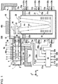
- FIG. 1 is a schematic diagram showing a configuration of a time-of-flight mass spectrometry device 100 according to the present embodiment.
- the time-of-flight mass spectrometry device 100 includes an ion introduction unit 1, a vacuum chamber 15 connected to the ion introduction unit 1, and a flight tube 21 provided inside the vacuum chamber 15.
- An ionization chamber 2 in the ion introduction unit 1 is provided with an ESI spray 3, as an ion source, for performing electrospray ionization (ESI).
- ESI spray 3 as an ion source, for performing electrospray ionization (ESI).
- ESI electrospray ionization
- the sample liquid is electrostatically sprayed from the ESI spray 3 to generate ions derived from the sample in the sample liquid.
- the ionization method is not limited to this. However, whichever ionization method is adopted, the ion source is a heat source, and its temperature fluctuates depending on the operating state.
- ions pass through a heating capillary 4, are converged by an ion guide 5 and reach an octapole type ion guide 7 through a skimmer 6.
- the ions converged by the ion guide 7 are introduced into a quadrupole mass filter 8, and only the ions having a specific mass-to-charge ratio according to the voltage applied to the quadrupole mass filter 8 pass through the quadrupole mass filter 8.
- These ions are introduced into a collision cell 10 as precursor ions, then the precursor ions are dissociated by collision with CID gas supplied into the collision cell 10 from outside of the collision cell 10, and various product ions are generated.
- a multi-pole ion guide 11 in the collision cell 10 functions as a kind of linear ion trap together with an inlet lens electrode 9a and an exit lens electrode 9b, and the generated product ions are temporarily accumulated. Then, the accumulated ions are discharged from the collision cell 10 at a predetermined timing, guided by an ion transport optical system 12, and introduced into the vacuum chamber 15 connected to the ion introduction unit 1.
- a vacuum pump is connected to the ion introduction unit 1 and the vacuum chamber 15, and the insides thereof are kept in a depressurized state.
- support members 22a and 22b (22a and 22b are collectively referred to as a support member 22) having insulating properties and high vibration absorption performance are provided. At least a part of the outer surface of the flight tube 21 having a substantially square tube shape or a substantially cylindrical shape is supported by the support member 22, and is supported by the vacuum chamber 15 via the support member 22.
- an orthogonal acceleration unit 16 and an ion detector 20 are respectively fixed to the flight tube 21 via support members (not shown).
- a reflector 19 composed of a number of annular or rectangular reflective electrodes is arranged at the lower side of the inside of the flight tube 21.
- a reflectron-type flight space FA in which ions are folded back by a reflective electric field formed by the reflector is provided inside the flight tube 21.
- the flight tube 21 is made of metal such as stainless steel, and a predetermined DC voltage is applied to the flight tube 21.
- a predetermined DC voltage is applied to the flight tube 21.
- different DC voltages are respectively applied based on the voltage applied to the flight tube 21.
- the reflective electric field is formed in the reflector, and flight space FA other than the reflective electric field has no electric field and no magnetic field and in a high vacuum.
- the ions traveling in the + X direction and introduced into the orthogonal acceleration unit 16 are accelerated in the -Z direction to start flying.
- the ions emitted from the orthogonal acceleration unit 16 first fly freely in the flight space FA, and then are turned back to the + Z direction by the reflective electric field formed by the reflector 19 and again fly freely in the flight space FA to reach the ion detector 20.
- the velocity of an ion in the flight space depends on the mass-to-charge ratio of the ion.
- ions having different mass-to-charge ratios introduced into the flight space FA at substantially the same time are separated according to respective mass-to-charge ratio during flight and reach the ion detector 20 with time lag.
- a detection signal by the ion detector 20 is input to a signal processing unit (not shown), and the flight time of each ion is converted into a mass-to-charge ratio to create a mass spectrum and perform mass spectrometry.
- the flight tube 21 expands due to heat, the flight distance changes, which causes an error in the measured value of the mass-to-charge ratio. Therefore, in the TOFMS according to the present embodiment, the flight tube 21 is provided inside the vacuum chamber 15 via the support member 22, and temperature adjustment elements H1a and H1b are provided on the vacuum chamber 15 in the vicinity of the connection portion with the support member 22.
- support members 22a and 22b for supporting the flight tube 21 are provided inside the vacuum chamber 15, and the support members 22 partially hold a side of the flight tube 21 close to the orthogonal acceleration portion 16 and the ion detector 20.
- temperature sensors T1a and T1b are provided in the vicinity of the connecting portion to which the support member 22 is connected.
- the temperatures of the vacuum chamber 15 and the support members 22a and 22b in the vicinity of the connection portion are measured by the temperature sensors T1a and T1b, and temperature measurement results are transmitted to a temperature control unit 30 as a temperature measurement signal S1a and a temperature measurement signal S1b.
- the temperature adjustment elements H1a and H1b such as an electric heaters are provided in the vicinity of the connection portion to which the support member 22 is connected, and the temperature of the connecting portion to which the support member 22 is connected is controlled to a predetermined temperature of, for example, 35 ⁇ or higher and 50 ⁇ or lower based on the temperature control signals C1a and C1b from the temperature control unit 30.
- FIG. 2 shows a sectional view of the vacuum chamber 15, the flight tube 21, and the support member 22 in the XY plane of FIG. 1 , at the portion where the support member 22 is provided.
- support members 22a to 22d are provided respectively and support the flight tube 21 having a quadrangular cross-sectional shape in the XY plane.
- the plurality of support members 22a and 22b are arranged on or near a plane (XY plane in FIG. 1 ) orthogonal to the longitudinal direction (Z direction in FIG. 1 ) of the flight tube 21.
- temperature sensors T1a to T1d and temperature adjustment elements H1a to H1d are provided respectively.
- the temperature measurement results by the temperature sensors T1c and T1d, which are omitted in FIG. 1 are also transmitted to the temperature control unit 30, and the temperature control unit 30 transmits the temperature control signals to the temperature adjustment elements H1c and H1d.
- the temperature sensors T1a to T1d may be referred to as a temperature sensor T1 in combining them or any one of them.
- the temperature adjustment elements H1a to H1d may be referred to as a temperature adjustment element H1 in combining them or any one of them.
- Mounting positions of the support members 22a to 22d are not limited to the four corners of the XY cross section of the vacuum chamber 15 as shown in FIG 2 , and an arbitrary number of the support members may be provided at an arbitrary number of positions such as another four positions, 6 positions, or 5 positions.
- the support member 22 may be a continuous member surrounding the flight tube 21. Even in this case, a plurality of the temperature sensors T1 and the temperature adjustment elements H1 can be arranged in the vicinity of the connection portion between the continuous support member 22 and the vacuum chamber 15 in the same manner as described above. Alternatively, only one temperature sensor T1 and only one temperature adjustment element H1 may be arranged.
- the temperature distribution of the vacuum chamber 15 and the flight tube 21 in the XY plane in FIG. 1 can be made more uniform.
- the side closer to the ion introduction unit 1 is susceptible to heat fluctuations from the ion introduction unit 1, and therefore temperature fluctuations are likely to occur.
- temperature non-uniformity caused by being near or far with respect to the ion introduction unit 1 can also be measured and corrected.
- the temperature control unit 30 independently controls the temperature adjustment elements H1a to H1d based on the measurement results of the temperature sensors T1a to T1d.
- the measurement result of the closest temperature sensor may be multiplied by the maximum weight, and the measurement results of other temperature sensors may also be multiplied by certain weight.
- control the plurality of temperature adjustment elements H1a to H1d by using representative values such as average value or median value of the measurement results of the plurality of temperature sensors T1a to T1d.
- the temperature sensor T1 and the temperature control portion H1 are provided in each of plurality of connection portions joined with the vacuum chamber 15.
- the two connection portions arranged relatively close to each other since the two support members 22 to be measured and to be temperature controlled are to be closed to each other, at least one of the temperature sensor T1 and the temperature adjustment element H1 can be omitted without arrangement.
- the number of the temperature sensors T1 and the temperature adjustment element H1 may be smaller than the number of the support members 22, respectively.
- the temperature sensor T1 and the temperature adjustment element H1 are both installed within 100 mm of distance (closest contact distance between the two) from the connection portion of the respective support member 22 and the vacuum chamber 15.
- the installation position of the temperature sensor T1 is more than 100 mm from the connection portion, it becomes difficult to accurately measure the temperature of the connection portion and the support member 22, and the temperature change of the flight tube 21 may occur.
- the installation position of the temperature adjustment element H1 is more than 100 mm from the connection portion, it becomes difficult to accurately control the temperature of the connection portion and the support member 22, and the temperature change of the flight tube 21 may occur.
- the installation positions of the temperature sensor T1 and the temperature adjustment element H1 should both be within 60 mm from the connection portion of the vacuum chamber 15 and the support member 22.
- the support member 22 is made of, for example, a PEEK (polyetheretherketone) resin having excellent insulating properties and high mechanical stability.
- the flight tube 21 is made of highly rigid stainless steel and the vacuum chamber 15 is made of stainless steel or a lightweight metal such as aluminum.
- thermosensor T1a and T1b as an example, a thermistor or a resistance temperature sensor such as platinum alloy is used. Further, as the temperature adjustment elements H1a and H1b, in addition to the above-mentioned electric heater, a member capable of heating and cooling such as a Peltier element can also be used.
- Power supply units 40a and 40b for respectively applying voltages to the in-vacuum electrodes are connected to the ion introduction unit 1 and the vacuum chamber (TOF section) 15.
- the power supply units 40a and 40b are also collectively referred to as a power supply unit 40.
- the power supply unit 40 includes a DC power supply applies DC voltage, an RF power supply applies AC voltage, a pulsar board as a switching board for applying pulse voltage to the extrusion electrode 17 and the extraction electrode 18, a digitizer board for digitizing the electric signal from the detector 20 and the like. These are also heat sources, and the calorific value changes depending on the operating conditions, and the temperatures of the ion introduction unit 1 and the TOF chamber 15 fluctuate.
- the temperature of the support member 22 is maintained at a constant temperature by the above configuration, so that even if the temperature of the ion introduction unit 1, the temperature of the vacuum chamber 15, or the ambient temperature of the device fluctuates, it is possible to prevent the temperature of the flight tube 21 from fluctuating. As a result, expansion and contraction of the flight tube 21 can be prevented, and a time-of-flight mass spectrometry device with high measurement accuracy can be realized.
- the ion introduction unit 1 in order to further suppress the inflow of heat from the ion introduction unit 1 and the heating capillary 4 which are heat sources to the flight tube 21, it is possible that at least a part of the ion introduction unit 1 is formed to contact with the device housing 14 at contact portions 13a and 13b and the portions 13a and 13b is formed of a high thermal conductive member. That is, by forming the contact portions 13a and 13b as a member having high thermal conductivity such as metal such as aluminum, the heat of the ion source (ESI spray) 3 in the ionization chamber 2 side can be dissipated to the apparatus housing 14. This makes it possible to further suppress the inflow of heat into the flight tube 21.
- ESI spray ion source
- the ion introduction unit 1 and the heating capillary 4 are in contact with the device housing 14 at a plurality of contact portions 13a and 13b having different distances from the flight tube 21 to each other, it is preferably provided with a high thermal conductive member on the contact portion 13a on the side far from the flight tube, that is, on the side close to the ionization chamber 2.
- the contact portion 13b on the side closer to the flight tube 21, that is, on the side far from the ionization chamber 2 is preferably formed of a member having a low thermal conductivity (for example, PEEK resin) instead of a high thermal conductive member.
- the ion introduction unit 1 and the vacuum chamber 15 are configured to be connected to the device housing 14 by a plurality of the connecting parts 13 to improve the mechanical strength of the entire device.
- the connection portion located near the heat source with respect to the vacuum chamber 15 containing the flight tube 21 is to be a high thermal conductive member with relatively high thermal conductivity
- the connection portion located far from the heat source with respect to the vacuum chamber 15 is to be a low heat conductive member having relatively low thermal conductivity.
- the device housing 14 is a housing that supports at least a part of, the ion introduction unit 1 and the vacuum chamber 15, and is preferably made of metal from the viewpoint of mechanical strength, EMC (Electro Magnetic Compatibility), and thermal conductivity. It is noted that, even in case that the contact portions 13a and 13b are not formed of the high thermal conductive member, that is, even in case that the heat of the ion introduction portion 1 is not positively dissipated to the device housing 14, the temperature of the vacuum chamber 15 fluctuates due to fluctuations in the temperature around the device.
- EMC Electro Magnetic Compatibility
- the contact portion 13c of the device housing 14 with the vacuum chamber 15 is preferably formed of a member (for example, PEEK resin) having a thermal conductivity lower than that of the above-mentioned high thermal conductive member.
- a member for example, PEEK resin
- the thermal resistance between the vacuum chamber 15 and the housing 14 increases, and even if the temperature of the vacuum chamber 15 fluctuates due to fluctuations in the temperature around the device or heat from the ion introduction unit 1, the effect of these becomes difficult to propagate to the vacuum chamber 15 and the temperature fluctuation of the flight tube can be suppressed.
- thermosensor T1 and the temperature adjustment element H1 may be further provided on the outer surface of the vacuum chamber 15 in order to control the temperature of the flight tube 21 with higher accuracy.
- second temperature sensors T2a, T2b and second temperature adjustment elements H2a, H2b can be provided on the outer surface of the vacuum chamber 15 corresponding to the middle position in the Z direction of the flight tube 21 .
- third temperature sensors T3a and T3b and third temperature adjustment elements H3a and H3b can be provided on the outer surface of the vacuum chamber 15 corresponding to the position near the lower end of the flight tube 21 in the Z direction.
- the second temperature sensors T2a and T2b are provided in the vicinity of the second temperature adjustment elements H2a and H2b, respectively.
- the third temperature sensors T3a and T3b are provided in the vicinity of the third temperature adjustment elements H3a and H3b, respectively.
- the temperature sensors T2a and T2b may be referred to as a temperature sensor T2 in combining them or any one of them.
- the temperature adjustment elements H2a and H2b may be referred to as a temperature adjustment element H2 in combining them or any one of them.
- the temperature sensors T3a, T3b may be referred to as the temperature sensor T3 in combining then or any one of them.
- the temperature adjustment elements H3a and H3b may be referred to as a temperature adjustment element H3 in combining them or any one of them.
- the second temperature sensors T2a and T2b, the second temperature adjustment elements H2a and H2b, the third temperature sensors T3a and T3b, and the third temperature adjustment elements H3a and H3b are provided at positions separated at least in the longitudinal direction of the flight tube 21 from the temperature sensor T1.
- the temperatures measured by the second temperature sensors T2a and T2b and the third temperature sensors T3a and T3b are transmitted to the temperature control unit 30 as temperature measurement signals S2a, S2b, S3a and S3b.
- the temperature control unit 30 transmits temperature control signals C2a, C2b, C3a, and C3b to the second temperature adjustment elements H2a, H2b and the third temperature adjustment elements H3a, H3b, so that temperatures of each part of the vacuum chamber 15 in which each temperature sensors are installed is controlled to have a predetermined temperature of, for example, 35 ⁇ or higher and 50 ⁇ or lower as described above.
- Number of each of the second temperature sensors T2, the second temperature adjustment elements H2, the third temperature sensors T3, and the third temperature adjustment elements H3 is not limited to two as shown in FIG. 1 , it may be any number such as four, six, or one. Further, each temperature sensor and each temperature adjustment element do not have to have one-to-one correspondence.
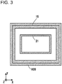
- At least one of the second temperature adjustment element H2 or the third temperature adjustment element H3 may be a continuous temperature adjustment element H20 surrounding the outer circumference of the vacuum chamber 15 as shown in FIG 3 .
- the temperature control unit 30 controls the first temperature adjustment element HI, the second temperature adjustment element H2, and a third temperature adjustment element H3 based on the measurement results of the temperature sensor T1, the second temperature sensor T2, and the third temperature sensor T3 so that each part at which each temperature adjustment element is installed in the vacuum chamber 15 has a predetermined temperature.
- the heat transfer from the vacuum chamber 15 to the flight tube 21 is limited to mainly heat conduction by the support member 22 or radiation heat transfer from the vacuum chamber 15 to the flight tube 21. Therefore, in order to control the temperature of the flight tube 21 with high accuracy by controlling the temperature of the vacuum chamber 15, it is preferable to improve the efficiency of radiation heat transfer from the vacuum chamber 15 to the flight tube 21.
- the inner wall surface of the vacuum chamber 15 can be surface-treated so as to increase radiation factor.
- aluminum is used as the material of the vacuum chamber 15, and a coating layer 15s by black nickel plating can be formed on the inner wall surface of the vacuum chamber 15 at least in the range facing the flight tube 21.
- black nickel plating is one of the commonly used plating for the purposes of antireflection or decoration, and its processing cost is relatively low.
- the coating layer 15s of black nickel plating By forming the coating layer 15s of black nickel plating, the surface becomes black and the radiation factor is improved.
- the radiation factor can be increased by about 10 times by forming the coating layer 15s of black nickel plating on the inner wall surface of the vacuum chamber 15 made of aluminum. According to this, the thermal resistance in the path of radiation heat transfer between the vacuum chamber 15 and the flight tube 21 is significantly reduced as compared with the conventional one (in which the coating layer 15s of black nickel plating is not formed), and the temperature stability of the flight tube 21 can be improved.
- the inner wall surface of the vacuum chamber 15 may be treated by ordinary nickel plating, or a coating layer may be formed by alumite processing.
- a coating layer capable for improving the radiation factor may be formed on the surface by a carbon film forming treatment, a ceramic spray treatment, other plating processing, a painting or coating processing, a thermal spray treatment, or the like.
- a thin plate or thin foil of other material having a higher radiation factor than the material of the vacuum chamber 15 may be attached to the inner wall surface of the vacuum chamber 15.
- a thin stainless steel plate may be attached to the inner wall surface of the above vacuum chamber 15 made of aluminum. This also increases the radiation factor of the inner wall surface of the vacuum chamber 15, so that the same effect as in the above embodiment can be achieved.
- the present invention is not limited to the contents of the above embodiments. Other modes that are conceivable within the scope of the technical idea of the present invention are also included within the scope of the present invention.
- the above embodiment is according to the reflectron-type TOFMS of the orthogonal acceleration type, however it does not necessary have to be the orthogonal acceleration type. It may have, for example, a configuration in which ions emitted from an ion trap are introduced into the flight space, or in which ions generated from a sample by a MALDI ion source are accelerated and put into the flight space. Further, not a reflectron-type but a linear type TOFMS may be used.
- Time-of-flight Mass Spectrometry Device 1 ... Ion Introduction Unit, 2 ... Ionization Chamber, 3 ... ESI Spray, 4 ... Heating Capillary, 5, 7, 11 ... Ion Guide, 6 ... Skimmer, 8 ... Quadrupole Mass Filter, 9a ... Inlet Lens Electrode, 9b ... Exit Lens Electrode, 10 ... Collision Cell, 12 ... Ion Transport Optical System, 13a, 13b ... Contact Portion, 13c ... Second Contact Portion, 14 ... Housing, 15 ... Vacuum Chamber (TOF Section), 16 ... Orthogonal Acceleration Unit, 17 ... Extrusion Electrode, 18 ... Extraction Electrode, FA ... Flight Space, FP ...
Landscapes
- Chemical & Material Sciences (AREA)
- Analytical Chemistry (AREA)
- Other Investigation Or Analysis Of Materials By Electrical Means (AREA)
Abstract
Description
- The present invention relates to a time-of-flight mass spectrometry device.
- In a time-of-flight mass spectrometry device (hereinafter, also referred to as TOFMS), a certain kinetic energy is applied to ions to be analyzed, and the ions are introduced into a flight space being formed in a flight tube to fly in the flight space. Then, the time required for each ion to fly a certain distance is measured, and the mass-to-charge ratio (m/z) of each ion is calculated based on the time of flight. Therefore, if the flight tube expands or contracts due to temperature change, the flight distance of the ions changes, and the flight time also changes, causing an error in the measured value of the mass-to-charge ratio.
- In order to avoid a measurement error caused by expansion and contraction of the flight tube due to temperature fluctuation and achieve high measurement accuracy, it has been proposed to install the flight tube in a thermostatic chamber (see Patent Literature 1 (PTL 1)).
- PTL 1: Japanese Laid-Open Patent Publication No.
2012-64437 - An ion source such as an electrospray ionization source (ESI) using a heated gas is used for the time-of-flight mass spectrometry device. Moreover, a capillary or an orifice, which is a vacuum partition for introducing ions generated by the ion source into a vacuum, is often heated for the purpose of promoting desolvation. In such case, the ion source and the capillary or orifice of the vacuum partition serve as heat sources. The heat generated in such a heat source is conducted through a structure that constitutes an ion path from the heat source to the flight tube, and is transmitted to the flight tube. The heat generation state of the ion source and the heating capillary fluctuates depending on operating conditions such as temperature conditions set according to the measurement conditions. Therefore, the temperature change of the flight tube due to the temperature change of the ion source and the heating capillary cannot be completely prevented and there was a problem that the expansion and contraction of the flight tube cannot be completely prevented only by installing the flight tube in the thermostatic chamber.
- Further, an ambient temperature change of the device propagates through the heat conduction path via the device housing to the flight tube and causes the temperature change of the flight tube. Because this temperature change is conducted to the flight tube through a support member or the like that supports the flight tube in a vacuum chamber, even if the flight tube is placed in the thermostatic chamber, the temperature change of the flight tube due to the ambient temperature change of the device cannot be completely avoided, and there was a problem that the expansion and contraction of the flight tube cannot be completely prevented.
- In the time-of-flight mass spectrometry device, various power supplies that can serve as heat sources are arranged in the device housing, and some power supplies are sometimes in direct contact with the vacuum chamber. The heat derived from such power supplies propagates through the structure that constitutes the path from the power supplies to the flight tube and is transmitted to the flight tube. The amount of heat generated by the power supply varies depending on operating conditions such as analysis conditions. Therefore, simply installing the flight tube in the thermostatic chamber cannot completely prevent the temperature change of the flight tube due to the change in the heat generation amount of the power supply, and thus, there was a problem that it is impossible to completely prevent the expansion and contraction of the flight tube.
- According to the 1st aspect of the present invention, a time-of-flight mass spectrometry device comprises: an ion introduction unit; a vacuum chamber connected to the ion introduction unit; a support member provided inside the vacuum chamber; a flight tube having a part of the outer surface supported by the support member and provided inside the vacuum chamber; a temperature sensor provided in the vicinity of a connection portion with the support member of the vacuum chamber; a temperature adjustment element provided in the vicinity of the connection portion; and a temperature control unit that controls the temperature adjustment element based on a measurement result of the temperature sensor.
- According to the 2nd aspect of the present invention, the time-of-flight mass spectrometry device is in the time-of-flight mass spectrometry device according to the 1st aspect, and it is preferable that the time-of-flight mass spectrometry device comprises a plurality of the support members, wherein: the temperature sensor and the temperature adjustment element are provided in the vicinity of a plurality of the connection portions connected to the support members in the vacuum chamber.
- According to the 3rd aspect of the present invention, the time-of-flight mass spectrometry device is in the time-of-flight mass spectrometry device according to the 2nd aspect, and it is preferable that a plurality of the support members are arranged on a plane orthogonal to the longitudinal direction of the flight tube or in the vicinity of the plane.
- According to the 4th aspect of the present invention, the time-of-flight mass spectrometry device is in the time-of-flight mass spectrometry device according to the 3rd aspect, and it is preferable that the time-of-flight mass spectrometry device further comprises: a second temperature sensor and a second temperature adjustment element provided on the outer surface of the vacuum chamber and at positions separated at least in the longitudinal direction of the flight tube from the temperature sensor, wherein: the temperature control unit controls the second temperature adjustment element based on a measurement result of the second temperature sensor.
- According to the 5th aspect of the present invention, the time-of-flight mass spectrometry device is in the time-of-flight mass spectrometry device according to the 4th aspect, and it is preferable that the time-of-flight mass spectrometry device further comprises: a third temperature sensor and a third temperature adjustment element provided on the outer surface of the vacuum chamber and at positions separated at least in the longitudinal direction of the flight tube from the second temperature sensor, wherein the temperature control unit controls the third temperature adjustment element based on a measurement result of the third temperature sensor.
- According to the 6th aspect of the present invention, the time-of-flight mass spectrometry device is in the time-of-flight mass spectrometry device according to any one of the 1st to 5th aspect, and it is preferable that an inner wall surface of the vacuum chamber facing the flight tube is subjected to radiation factor improvement treatment.
- According to the 7th aspect of the present invention, the time-of-flight mass spectrometry device is in the time-of-flight mass spectrometry device according to the 6th aspect, and it is preferable that the ion introduction unit has a contact portion with a device housing, and the ion introduction unit is in thermal contact with the device housing via a high thermal conductive member at at least a part of the contact portion.
- According to the 8th aspect of the present invention, the time-of-flight mass spectrometry device is in the time-of-flight mass spectrometry device according to any one of the 1st to 5th aspect, and it is preferable that the ion introduction unit has a contact portion with a device housing, and the ion introduction unit is in thermal contact with the device housing via a high thermal conductive member at at least a part of the contact portion.
- According to the 9th aspect of the present invention, the time-of-flight mass spectrometry device is in the time-of-flight mass spectrometry device according to the 8th aspect, and it is preferable that the contact portions are a plurality of locations having different distances from the flight tube, and the high thermal conductive member is provided on a contact portion among a plurality of the contact portions that is far from the flight tube.
- According to the 10th aspect of the present invention, the time-of-flight mass spectrometry device is in the time-of-flight mass spectrometry device according to any one of the 1st to 5th aspect, and it is preferable that the vacuum chamber has a second contact portion that contacts with the device housing, and the vacuum chamber is in thermal contact with a device housing via a low heat conductive member at at least a part of the second contact portion.
- According to the 11th aspect of the present invention, the time-of-flight mass spectrometry device is in the time-of-flight mass spectrometry device according to the 6th aspect, and it is preferable that the vacuum chamber has a second contact portion that contacts with the device housing, and the vacuum chamber is in thermal contact with a device housing via a low heat conductive member at at least a part of the second contact portion.
- According to the 12th aspect of the present invention, the time-of-flight mass spectrometry device is in the time-of-flight mass spectrometry device according to the 7th aspect, and it is preferable that the vacuum chamber has a second contact portion that contacts with the device housing, and the vacuum chamber is in thermal contact with the device housing via a low heat conductive member at at least a part of the second contact portion.
- According to the 13th aspect of the present invention, the time-of-flight mass spectrometry device is in the time-of-flight mass spectrometry device according to the 8th aspect, and it is preferable that the vacuum chamber has a second contact portion that contacts with the device housing, and the vacuum chamber is in thermal contact with the device housing via a low heat conductive member at at least a part of the second contact portion.
- According to the present invention, it is possible to prevent temperature change of the flight tube and expansion and contraction thereof due to the temperature change, and it is possible to realize a time-of-flight mass spectrometry device with high measurement accuracy.
-
- [
FIG. 1] FIG. 1 is a schematic diagram showing a configuration of a time-of-flight mass spectrometry device according to one embodiment. - [
FIG. 2] FIG. 2 is a schematic view showing a vicinity of a support member that supports a flight tube in a time-of-flight mass spectrometry device according to one embodiment. - [
FIG. 3] FIG. 3 is a schematic diagram showing a variation of a second temperature adjustment element. -
FIG. 1 is a schematic diagram showing a configuration of a time-of-flightmass spectrometry device 100 according to the present embodiment. The time-of-flightmass spectrometry device 100 includes anion introduction unit 1, avacuum chamber 15 connected to theion introduction unit 1, and aflight tube 21 provided inside thevacuum chamber 15. - An
ionization chamber 2 in theion introduction unit 1 is provided with anESI spray 3, as an ion source, for performing electrospray ionization (ESI). Upon supplying a sample liquid containing components to be analyzed to theESI spray 3, the sample liquid is electrostatically sprayed from theESI spray 3 to generate ions derived from the sample in the sample liquid. It is to be noted that the ionization method is not limited to this. However, whichever ionization method is adopted, the ion source is a heat source, and its temperature fluctuates depending on the operating state. - Generated various ions pass through a heating capillary 4, are converged by an ion guide 5 and reach an octapole type ion guide 7 through a skimmer 6. The ions converged by the ion guide 7 are introduced into a
quadrupole mass filter 8, and only the ions having a specific mass-to-charge ratio according to the voltage applied to thequadrupole mass filter 8 pass through thequadrupole mass filter 8. These ions are introduced into acollision cell 10 as precursor ions, then the precursor ions are dissociated by collision with CID gas supplied into thecollision cell 10 from outside of thecollision cell 10, and various product ions are generated. - A
multi-pole ion guide 11 in thecollision cell 10 functions as a kind of linear ion trap together with aninlet lens electrode 9a and anexit lens electrode 9b, and the generated product ions are temporarily accumulated. Then, the accumulated ions are discharged from thecollision cell 10 at a predetermined timing, guided by an ion transportoptical system 12, and introduced into thevacuum chamber 15 connected to theion introduction unit 1. - Although not shown, a vacuum pump is connected to the
ion introduction unit 1 and thevacuum chamber 15, and the insides thereof are kept in a depressurized state. - Inside the
vacuum chamber 15, supportmembers flight tube 21 having a substantially square tube shape or a substantially cylindrical shape is supported by the support member 22, and is supported by thevacuum chamber 15 via the support member 22. - Moreover, an
orthogonal acceleration unit 16 and anion detector 20 are respectively fixed to theflight tube 21 via support members (not shown). Areflector 19 composed of a number of annular or rectangular reflective electrodes is arranged at the lower side of the inside of theflight tube 21. Thereby, a reflectron-type flight space FA in which ions are folded back by a reflective electric field formed by the reflector is provided inside theflight tube 21. - The
flight tube 21 is made of metal such as stainless steel, and a predetermined DC voltage is applied to theflight tube 21. To the plurality of reflective electrodes constituting the reflector, different DC voltages are respectively applied based on the voltage applied to theflight tube 21. Thereby, the reflective electric field is formed in the reflector, and flight space FA other than the reflective electric field has no electric field and no magnetic field and in a high vacuum. - By being formed a predetermined electric field between an
extrusion electrode 17 and anextraction electrode 18 at a predetermined timing, the ions traveling in the + X direction and introduced into theorthogonal acceleration unit 16 are accelerated in the -Z direction to start flying. As shown in broken line flight paths FP, the ions emitted from theorthogonal acceleration unit 16 first fly freely in the flight space FA, and then are turned back to the + Z direction by the reflective electric field formed by thereflector 19 and again fly freely in the flight space FA to reach theion detector 20. The velocity of an ion in the flight space depends on the mass-to-charge ratio of the ion. Therefore, ions having different mass-to-charge ratios introduced into the flight space FA at substantially the same time are separated according to respective mass-to-charge ratio during flight and reach theion detector 20 with time lag. A detection signal by theion detector 20 is input to a signal processing unit (not shown), and the flight time of each ion is converted into a mass-to-charge ratio to create a mass spectrum and perform mass spectrometry. - If the
flight tube 21 expands due to heat, the flight distance changes, which causes an error in the measured value of the mass-to-charge ratio. Therefore, in the TOFMS according to the present embodiment, theflight tube 21 is provided inside thevacuum chamber 15 via the support member 22, and temperature adjustment elements H1a and H1b are provided on thevacuum chamber 15 in the vicinity of the connection portion with the support member 22. - More specifically, as shown in
FIG. 1 ,support members flight tube 21 are provided inside thevacuum chamber 15, and the support members 22 partially hold a side of theflight tube 21 close to theorthogonal acceleration portion 16 and theion detector 20. - Of the
vacuum chamber 15, temperature sensors T1a and T1b are provided in the vicinity of the connecting portion to which the support member 22 is connected. The temperatures of thevacuum chamber 15 and thesupport members temperature control unit 30 as a temperature measurement signal S1a and a temperature measurement signal S1b. - Of the
vacuum chamber 15, the temperature adjustment elements H1a and H1b such as an electric heaters are provided in the vicinity of the connection portion to which the support member 22 is connected, and the temperature of the connecting portion to which the support member 22 is connected is controlled to a predetermined temperature of, for example, 35 □ or higher and 50 □ or lower based on the temperature control signals C1a and C1b from thetemperature control unit 30. -
FIG. 2 shows a sectional view of thevacuum chamber 15, theflight tube 21, and the support member 22 in the XY plane ofFIG. 1 , at the portion where the support member 22 is provided. - At each of four corners of the inner surface of the
vacuum chamber 15 having a quadrangular cross-sectional shape in the XY plane,support members 22a to 22d are provided respectively and support theflight tube 21 having a quadrangular cross-sectional shape in the XY plane. In other words, the plurality ofsupport members FIG. 1 ) orthogonal to the longitudinal direction (Z direction inFIG. 1 ) of theflight tube 21. By arranging the plurality ofsupport members flight tube 21 in this way, theflight tube 21 can be held while preventing deformation. - On the outer surface of the
vacuum chamber 15 and in the vicinity of the connecting portions connecting thesupport members 22a to 22d and thevacuum chamber 15, temperature sensors T1a to T1d and temperature adjustment elements H1a to H1d are provided respectively. The temperature measurement results by the temperature sensors T1c and T1d, which are omitted inFIG. 1 , are also transmitted to thetemperature control unit 30, and thetemperature control unit 30 transmits the temperature control signals to the temperature adjustment elements H1c and H1d. - Hereinafter, the temperature sensors T1a to T1d may be referred to as a temperature sensor T1 in combining them or any one of them. Further, the temperature adjustment elements H1a to H1d may be referred to as a temperature adjustment element H1 in combining them or any one of them.
- Mounting positions of the
support members 22a to 22d are not limited to the four corners of the XY cross section of thevacuum chamber 15 as shown inFIG 2 , and an arbitrary number of the support members may be provided at an arbitrary number of positions such as another four positions, 6 positions, or 5 positions. - Alternatively, the support member 22 may be a continuous member surrounding the
flight tube 21. Even in this case, a plurality of the temperature sensors T1 and the temperature adjustment elements H1 can be arranged in the vicinity of the connection portion between the continuous support member 22 and thevacuum chamber 15 in the same manner as described above. Alternatively, only one temperature sensor T1 and only one temperature adjustment element H1 may be arranged. - By arranging a plurality of temperature sensors T1 and temperature adjustment elements HI, the temperature distribution of the
vacuum chamber 15 and theflight tube 21 in the XY plane inFIG. 1 can be made more uniform. For example, of thevacuum chamber 15, theflight tube 21, and the support member 22, the side closer to theion introduction unit 1 is susceptible to heat fluctuations from theion introduction unit 1, and therefore temperature fluctuations are likely to occur. However, by arranging a plurality of the temperature sensors T1 and the temperature adjustment elements HI, temperature non-uniformity caused by being near or far with respect to theion introduction unit 1 can also be measured and corrected. - In this case, it is preferable that the
temperature control unit 30 independently controls the temperature adjustment elements H1a to H1d based on the measurement results of the temperature sensors T1a to T1d. - Alternatively, in the control of the temperature adjustment elements H1a to H1d, among the temperature sensors T1a to T1d, the measurement result of the closest temperature sensor may be multiplied by the maximum weight, and the measurement results of other temperature sensors may also be multiplied by certain weight.
- It is to be noted, it is also possible to control the plurality of temperature adjustment elements H1a to H1d by using representative values such as average value or median value of the measurement results of the plurality of temperature sensors T1a to T1d.
- In case the support member 22 is separated into a plurality of parts as in the example of
FIG. 2 , it is preferable that the temperature sensor T1 and the temperature control portion H1 are provided in each of plurality of connection portions joined with thevacuum chamber 15. - However, in the two connection portions arranged relatively close to each other, since the two support members 22 to be measured and to be temperature controlled are to be closed to each other, at least one of the temperature sensor T1 and the temperature adjustment element H1 can be omitted without arrangement. Thus, the number of the temperature sensors T1 and the temperature adjustment element H1 may be smaller than the number of the support members 22, respectively.
- It is desirable that the temperature sensor T1 and the temperature adjustment element H1 are both installed within 100 mm of distance (closest contact distance between the two) from the connection portion of the respective support member 22 and the
vacuum chamber 15. - If the installation position of the temperature sensor T1 is more than 100 mm from the connection portion, it becomes difficult to accurately measure the temperature of the connection portion and the support member 22, and the temperature change of the
flight tube 21 may occur. - Moreover, if the installation position of the temperature adjustment element H1 is more than 100 mm from the connection portion, it becomes difficult to accurately control the temperature of the connection portion and the support member 22, and the temperature change of the
flight tube 21 may occur. - In order to control the temperature of the
flight tube 21 with higher accuracy, it is more preferable that the installation positions of the temperature sensor T1 and the temperature adjustment element H1 should both be within 60 mm from the connection portion of thevacuum chamber 15 and the support member 22. - Since a high voltage of several kV is applied to almost the
entire flight tube 21, it is preferable that the support member 22 is made of, for example, a PEEK (polyetheretherketone) resin having excellent insulating properties and high mechanical stability. - Further, it is preferable that the
flight tube 21 is made of highly rigid stainless steel and thevacuum chamber 15 is made of stainless steel or a lightweight metal such as aluminum. - As the temperature sensors T1a and T1b, as an example, a thermistor or a resistance temperature sensor such as platinum alloy is used. Further, as the temperature adjustment elements H1a and H1b, in addition to the above-mentioned electric heater, a member capable of heating and cooling such as a Peltier element can also be used.
-
Power supply units ion introduction unit 1 and the vacuum chamber (TOF section) 15. Thepower supply units extrusion electrode 17 and theextraction electrode 18, a digitizer board for digitizing the electric signal from thedetector 20 and the like. These are also heat sources, and the calorific value changes depending on the operating conditions, and the temperatures of theion introduction unit 1 and theTOF chamber 15 fluctuate. - In the TOFMS according to the present embodiment, the temperature of the support member 22 is maintained at a constant temperature by the above configuration, so that even if the temperature of the
ion introduction unit 1, the temperature of thevacuum chamber 15, or the ambient temperature of the device fluctuates, it is possible to prevent the temperature of theflight tube 21 from fluctuating. As a result, expansion and contraction of theflight tube 21 can be prevented, and a time-of-flight mass spectrometry device with high measurement accuracy can be realized. - As shown in
FIG. 1 , in order to further suppress the inflow of heat from theion introduction unit 1 and the heating capillary 4 which are heat sources to theflight tube 21, it is possible that at least a part of theion introduction unit 1 is formed to contact with thedevice housing 14 atcontact portions portions contact portions ionization chamber 2 side can be dissipated to theapparatus housing 14. This makes it possible to further suppress the inflow of heat into theflight tube 21. - Further, as shown in
FIG. 1 , in case theion introduction unit 1 and the heating capillary 4 are in contact with thedevice housing 14 at a plurality ofcontact portions flight tube 21 to each other, it is preferably provided with a high thermal conductive member on thecontact portion 13a on the side far from the flight tube, that is, on the side close to theionization chamber 2. In this case, thecontact portion 13b on the side closer to theflight tube 21, that is, on the side far from theionization chamber 2, is preferably formed of a member having a low thermal conductivity (for example, PEEK resin) instead of a high thermal conductive member. - Generally, the
ion introduction unit 1 and thevacuum chamber 15 are configured to be connected to thedevice housing 14 by a plurality of the connecting parts 13 to improve the mechanical strength of the entire device. In the TOFMS according to the present embodiment, among the plurality of connection portions 13, the connection portion located near the heat source with respect to thevacuum chamber 15 containing theflight tube 21 is to be a high thermal conductive member with relatively high thermal conductivity, and the connection portion located far from the heat source with respect to the vacuum chamber 15 (that is, a position close to the vacuum chamber 15) is to be a low heat conductive member having relatively low thermal conductivity. As a result, temperature stability of the flight tube can be improved while ensuring the desired mechanical strength. - The
device housing 14 is a housing that supports at least a part of, theion introduction unit 1 and thevacuum chamber 15, and is preferably made of metal from the viewpoint of mechanical strength, EMC (Electro Magnetic Compatibility), and thermal conductivity. It is noted that, even in case that thecontact portions ion introduction portion 1 is not positively dissipated to thedevice housing 14, the temperature of thevacuum chamber 15 fluctuates due to fluctuations in the temperature around the device. Therefore, thecontact portion 13c of thedevice housing 14 with thevacuum chamber 15 is preferably formed of a member (for example, PEEK resin) having a thermal conductivity lower than that of the above-mentioned high thermal conductive member. Thereby, the thermal resistance between thevacuum chamber 15 and thehousing 14 increases, and even if the temperature of thevacuum chamber 15 fluctuates due to fluctuations in the temperature around the device or heat from theion introduction unit 1, the effect of these becomes difficult to propagate to thevacuum chamber 15 and the temperature fluctuation of the flight tube can be suppressed. - In addition to the temperature sensor T1 and the temperature adjustment element H1 described above, other temperature sensor and other temperature adjustment element may be further provided on the outer surface of the
vacuum chamber 15 in order to control the temperature of theflight tube 21 with higher accuracy. - As an example, as shown in
FIG. 1 , on the outer surface of thevacuum chamber 15 corresponding to the middle position in the Z direction of theflight tube 21, second temperature sensors T2a, T2b and second temperature adjustment elements H2a, H2b can be provided. Similarly, third temperature sensors T3a and T3b and third temperature adjustment elements H3a and H3b can be provided on the outer surface of thevacuum chamber 15 corresponding to the position near the lower end of theflight tube 21 in the Z direction. - It is preferable that the second temperature sensors T2a and T2b are provided in the vicinity of the second temperature adjustment elements H2a and H2b, respectively. Similarly, it is preferable that the third temperature sensors T3a and T3b are provided in the vicinity of the third temperature adjustment elements H3a and H3b, respectively.
- Hereinafter, the temperature sensors T2a and T2b may be referred to as a temperature sensor T2 in combining them or any one of them. Further, the temperature adjustment elements H2a and H2b may be referred to as a temperature adjustment element H2 in combining them or any one of them.
- Similarly, the temperature sensors T3a, T3b may be referred to as the temperature sensor T3 in combining then or any one of them. Further, the temperature adjustment elements H3a and H3b may be referred to as a temperature adjustment element H3 in combining them or any one of them.
- In these examples, the second temperature sensors T2a and T2b, the second temperature adjustment elements H2a and H2b, the third temperature sensors T3a and T3b, and the third temperature adjustment elements H3a and H3b are provided at positions separated at least in the longitudinal direction of the
flight tube 21 from the temperature sensor T1. - The temperatures measured by the second temperature sensors T2a and T2b and the third temperature sensors T3a and T3b are transmitted to the
temperature control unit 30 as temperature measurement signals S2a, S2b, S3a and S3b. Thetemperature control unit 30 transmits temperature control signals C2a, C2b, C3a, and C3b to the second temperature adjustment elements H2a, H2b and the third temperature adjustment elements H3a, H3b, so that temperatures of each part of thevacuum chamber 15 in which each temperature sensors are installed is controlled to have a predetermined temperature of, for example, 35 □ or higher and 50 □ or lower as described above. - Number of each of the second temperature sensors T2, the second temperature adjustment elements H2, the third temperature sensors T3, and the third temperature adjustment elements H3 is not limited to two as shown in
FIG. 1 , it may be any number such as four, six, or one. Further, each temperature sensor and each temperature adjustment element do not have to have one-to-one correspondence. - Moreover, at least one of the second temperature adjustment element H2 or the third temperature adjustment element H3 may be a continuous temperature adjustment element H20 surrounding the outer circumference of the
vacuum chamber 15 as shown inFIG 3 . - The
temperature control unit 30 controls the first temperature adjustment element HI, the second temperature adjustment element H2, and a third temperature adjustment element H3 based on the measurement results of the temperature sensor T1, the second temperature sensor T2, and the third temperature sensor T3 so that each part at which each temperature adjustment element is installed in thevacuum chamber 15 has a predetermined temperature. - Since inside of the
vacuum chamber 15 is maintained in high vacuum, the heat transfer from thevacuum chamber 15 to theflight tube 21 is limited to mainly heat conduction by the support member 22 or radiation heat transfer from thevacuum chamber 15 to theflight tube 21. Therefore, in order to control the temperature of theflight tube 21 with high accuracy by controlling the temperature of thevacuum chamber 15, it is preferable to improve the efficiency of radiation heat transfer from thevacuum chamber 15 to theflight tube 21. - In order to increase the efficiency of this radiation heat transfer, the inner wall surface of the
vacuum chamber 15 can be surface-treated so as to increase radiation factor. Specifically, aluminum is used as the material of thevacuum chamber 15, and acoating layer 15s by black nickel plating can be formed on the inner wall surface of thevacuum chamber 15 at least in the range facing theflight tube 21. - As is well known, black nickel plating is one of the commonly used plating for the purposes of antireflection or decoration, and its processing cost is relatively low. By forming the
coating layer 15s of black nickel plating, the surface becomes black and the radiation factor is improved. According to the experiment of the present inventor, it has been confirmed that the radiation factor can be increased by about 10 times by forming thecoating layer 15s of black nickel plating on the inner wall surface of thevacuum chamber 15 made of aluminum. According to this, the thermal resistance in the path of radiation heat transfer between thevacuum chamber 15 and theflight tube 21 is significantly reduced as compared with the conventional one (in which thecoating layer 15s of black nickel plating is not formed), and the temperature stability of theflight tube 21 can be improved. - It is to be noted that, the inner wall surface of the
vacuum chamber 15 may be treated by ordinary nickel plating, or a coating layer may be formed by alumite processing. Alternatively, a coating layer capable for improving the radiation factor may be formed on the surface by a carbon film forming treatment, a ceramic spray treatment, other plating processing, a painting or coating processing, a thermal spray treatment, or the like. - Further, not forming a coating layer made of a material different from the material of the
vacuum chamber 15, but the surface of thevacuum chamber 15 itself may be chemically or physically scraped to form irregularities. - Alternatively, a thin plate or thin foil of other material having a higher radiation factor than the material of the
vacuum chamber 15 may be attached to the inner wall surface of thevacuum chamber 15. Specifically, a thin stainless steel plate may be attached to the inner wall surface of theabove vacuum chamber 15 made of aluminum. This also increases the radiation factor of the inner wall surface of thevacuum chamber 15, so that the same effect as in the above embodiment can be achieved. - According to the above-described one embodiment, the following effects can be obtained.
- (1) A time-of-flight mass spectrometry device according to one embodiment, comprises:
- an
ion introduction unit 1; avacuum chamber 15 connected to theion introduction unit 1; - a support member 22 provided inside the
vacuum chamber 15; aflight tube 21 having a part of the outer surface supported by the support member 22 and provided inside thevacuum chamber 15; a temperature sensor T1 provided in the vicinity of a connection portion with the support member 22 of thevacuum chamber 15; a temperature adjustment element H1 provided in the vicinity of the connection portion; and atemperature control unit 30 that controls the temperature adjustment element H1 based on a measurement result of the temperature sensor T1.
With this configuration, even if the temperature of theion introduction unit 1, the temperature of thevacuum chamber 15, the ambient temperature of the device, or the calorific value of the power supply unit 40 fluctuates, it is possible to prevent the temperature of theflight tube 21 from fluctuating. Thereby, expansion and contraction of theflight tube 21 by temperature fluctuation can be prevented, and a time-of-flight mass spectrometry device with high measurement accuracy can be realized. - an
- (2) In the time-of-flight mass spectrometry device of above described one embodiment, the time-of-flight mass spectrometry device comprises a plurality of the support members 22, wherein: the temperature sensor T1 and the temperature adjustment element H1 are provided in the vicinity of a plurality of the connection portions connected to the support members 22 in the
vacuum chamber 15. Thereby, it is possible to further prevent temperature of theflight tube 21 from fluctuating and a time-of-flight mass spectrometry device with high measurement accuracy can be realized. - (3) The time-of-flight mass spectrometry device in above described (2), wherein: a plurality of the support members 22 are arranged on a plane orthogonal to the longitudinal direction of the
flight tube 21 or in the vicinity of the plane. Thereby, it is possible to further prevent theflight tube 21 from fluctuating and a time-of-flight mass spectrometry device with further high measurement accuracy can be realized. - (4) The time-of-flight mass spectrometry device in above described (3), further comprises: a second temperature sensor T2 and a second temperature adjustment element H2 provided on the outer surface of the
vacuum chamber 15 and at positions separated at least in the longitudinal direction of theflight tube 21 from the temperature sensor T1, wherein: thetemperature control unit 30 controls the second temperature adjustment element H2 based on a measurement result of the second temperature sensor T2. Thereby, it is possible to further prevent temperature of theflight tube 21 from fluctuating and a time-of-flight mass spectrometry device with further high measurement accuracy can be realized. It is to be noted that, the first temperature control unit H1 or the second temperature control unit H2 may be controlled based on the measurement results of both the second temperature sensor T2 and the first temperature sensor T1. - (5) The time-of-flight mass spectrometry device of above described (4), further comprised: a third temperature sensor T3 and a third temperature adjustment element H3 provided on the outer surface of the
vacuum chamber 15 and at positions separated at least in the longitudinal direction of theflight tube 21 from the second temperature sensor T2, wherein: thetemperature control unit 30 controls the third temperature adjustment element H3 based on a measurement result of the third temperature sensor T3. Thereby, it is possible to further prevent temperature of theflight tube 21 from fluctuating and a time-of-flight mass spectrometry device with further high measurement accuracy can be realized. It is to be noted that, any of the first temperature control unit HI, the second temperature control unit H2 and the third temperature control unit H3 may be controlled based on a plurality of measurement results from among of the first temperature sensor T1, the second temperature sensor T2 and the third temperature sensor T3. - (6) In the time-of-flight mass spectrometry device of above described one embodiment, wherein: an inner wall surface of the
vacuum chamber 15 facing theflight tube 21 is subjected to radiation factor improvement treatment. Thereby, it is possible to further prevent temperature of theflight tube 21 from fluctuating and a time-of-flight mass spectrometry device with further high measurement accuracy can be realized. Further, the temperature stabilization time of the flight tube is shortened, the time until the measurement can be started when the device is started is shortened, and the time-of-flight mass spectrometer with high measurement efficiency can be realized. - (7) In the time-of-flight mass spectrometry device of above described one embodiment, wherein: the
ion introduction unit 1 hascontact portions device housing 14, and theion introduction unit 1 is in thermal contact with thedevice housing 14 via the high thermalconductive members contact portions ion introduction unit 1 to theflight tube 21 can be reduced, and the temperature fluctuation of theflight tube 21 can be further prevented. - (8) The time-of-flight mass spectrometry device of above described (7), wherein: the
contact portions flight tube 21, and the high thermalconductive member 13a is provided on acontact portion 13a among a plurality of thecontact portions flight tube 21. Thereby, the heat conducted from theion introduction unit 1 to theflight tube 21 can be reduced, and the temperature fluctuation of theflight tube 21 can be further prevented. - (9) The time-of-flight mass spectrometry device of above described (1) through (8), wherein: the
vacuum chamber 15 has thesecond contact portion 13c that contacts with thedevice housing 14, and thevacuum chamber 15 is in thermal contact with thedevice housing 14 via the low heatconductive member 13c. Thereby, the heat conducted from thedevice housing 14 to theflight tube 21 can be reduced, and the temperature fluctuation of theflight tube 21 can be further prevented. - The present invention is not limited to the contents of the above embodiments. Other modes that are conceivable within the scope of the technical idea of the present invention are also included within the scope of the present invention.
- The above embodiment is according to the reflectron-type TOFMS of the orthogonal acceleration type, however it does not necessary have to be the orthogonal acceleration type. It may have, for example, a configuration in which ions emitted from an ion trap are introduced into the flight space, or in which ions generated from a sample by a MALDI ion source are accelerated and put into the flight space. Further, not a reflectron-type but a linear type TOFMS may be used.
- 100 ... Time-of-flight Mass Spectrometry Device, 1 ... Ion Introduction Unit, 2 ... Ionization Chamber, 3 ... ESI Spray, 4 ... Heating Capillary, 5, 7, 11 ... Ion Guide, 6 ... Skimmer, 8 ... Quadrupole Mass Filter, 9a ... Inlet Lens Electrode, 9b ... Exit Lens Electrode, 10 ... Collision Cell, 12 ... Ion Transport Optical System, 13a, 13b ... Contact Portion, 13c ... Second Contact Portion, 14 ... Housing, 15 ... Vacuum Chamber (TOF Section), 16 ... Orthogonal Acceleration Unit, 17 ... Extrusion Electrode, 18 ... Extraction Electrode, FA ... Flight Space, FP ... Flight Path, 19 ... Reflector, 20 ... Ion Detector, 21 ... Flight Tube, 22 ... Support Member, 30 ... Temperature Control Unit, H1a, H1b, H1c, H1d ... Temperature Adjustment Element, H2a, H2b ... Second Temperature Adjustment Element, H3a, H3b ... Third Temperature Adjustment Element, T1a, T1b, T1c, T1d ... Temperature Sensor, T2a, T2b ... Second Temperature Sensor, T3a, T3b ... Third Temperature Sensor, 40 ... Power Supply Unit
Claims (13)
- A time-of-flight mass spectrometry device, comprising:an ion introduction unit;a vacuum chamber connected to the ion introduction unit;a support member provided inside the vacuum chamber;a flight tube having a part of the outer surface supported by the support member and provided inside the vacuum chamber;a temperature sensor provided in the vicinity of a connection portion with the support member of the vacuum chamber;a temperature adjustment element provided in the vicinity of the connection portion; anda temperature control unit that controls the temperature adjustment element based on a measurement result of the temperature sensor.
- The time-of-flight mass spectrometry device according to claim 1, comprising:
a plurality of the support members, wherein:
the temperature sensor and the temperature adjustment element are provided in the vicinity of a plurality of the connection portions connected to the support members in the vacuum chamber. - The time-of-flight mass spectrometry device according to claim 2, wherein:
a plurality of the support members are arranged on a plane orthogonal to the longitudinal direction of the flight tube or in the vicinity of the plane. - The time-of-flight mass spectrometry device according to claim 3, further comprising:
a second temperature sensor and a second temperature adjustment element provided on the outer surface of the vacuum chamber and at positions separated at least in the longitudinal direction of the flight tube from the temperature sensor, wherein:
the temperature control unit controls the second temperature adjustment element based on a measurement result of the second temperature sensor. - The time-of-flight mass spectrometry device according to claim 4, further comprising:
a third temperature sensor and a third temperature adjustment element provided on the outer surface of the vacuum chamber and at positions separated at least in the longitudinal direction of the flight tube from the second temperature sensor, wherein:
the temperature control unit controls the third temperature adjustment element based on a measurement result of the third temperature sensor. - The time-of-flight mass spectrometry device according to any one of claims 1 to 5, wherein:
an inner wall surface of the vacuum chamber facing the flight tube is subjected to radiation factor improvement treatment. - The time-of-flight mass spectrometry device according to claim 6, wherein:
the ion introduction unit has a contact portion with a device housing, and the ion introduction unit is in thermal contact with the device housing via a high thermal conductive member at at least a part of the contact portion. - The time-of-flight mass spectrometry device according to any one of claims 1 to 5, wherein:
the ion introduction unit has a contact portion with a device housing, and the ion introduction unit is in thermal contact with the device housing via a high thermal conductive member at at least a part of the contact portion. - The time-of-flight mass spectrometry device according to claim 8, wherein:the contact portions are a plurality of locations having different distances from the flight tube, andthe high thermal conductive member is provided on a contact portion among a plurality of the contact portions that is far from the flight tube.
- The time-of-flight mass spectrometry device according to any one of claims 1 to 5, wherein:
the vacuum chamber has a second contact portion that contacts with a device housing, and the vacuum chamber is in thermal contact with the device housing via a low heat conductive member at at least a part of the second contact portion. - The time-of-flight mass spectrometry device according to claim 6, wherein:
the vacuum chamber has a second contact portion that contacts with the device housing, and the vacuum chamber is in thermal contact with the device housing via a low heat conductive member at at least a part of the second contact portion. - The time-of-flight mass spectrometry device according to claim 7, wherein:
the vacuum chamber has a second contact portion that contacts with the device housing, and the vacuum chamber is in thermal contact with the device housing via a low heat conductive member at at least a part of the second contact portion. - The time-of-flight mass spectrometry device according to claim 8, wherein:
the vacuum chamber has a second contact portion that contacts with the device housing, and the vacuum chamber is in thermal contact with the device housing via a low heat conductive member at at least a part of the second contact portion.
Applications Claiming Priority (1)
| Application Number | Priority Date | Filing Date | Title |
|---|---|---|---|
| PCT/JP2018/019854 WO2019224948A1 (en) | 2018-05-23 | 2018-05-23 | Time-of-flight mass spectrometer |
Publications (3)
| Publication Number | Publication Date |
|---|---|
| EP3799107A1 true EP3799107A1 (en) | 2021-03-31 |
| EP3799107A4 EP3799107A4 (en) | 2022-05-11 |
| EP3799107B1 EP3799107B1 (en) | 2026-02-25 |
Family
ID=68616811
Family Applications (1)
| Application Number | Title | Priority Date | Filing Date |
|---|---|---|---|
| EP18919667.8A Active EP3799107B1 (en) | 2018-05-23 | 2018-05-23 | Time-of-flight mass spectrometry device |
Country Status (5)
| Country | Link |
|---|---|
| US (1) | US11443934B2 (en) |
| EP (1) | EP3799107B1 (en) |
| JP (1) | JP6989005B2 (en) |
| CN (1) | CN112154529B (en) |
| WO (1) | WO2019224948A1 (en) |
Families Citing this family (12)
| Publication number | Priority date | Publication date | Assignee | Title |
|---|---|---|---|---|
| WO2019111290A1 (en) * | 2017-12-04 | 2019-06-13 | 株式会社島津製作所 | Time-of-flight type mass spectrometry device |
| GB201808932D0 (en) | 2018-05-31 | 2018-07-18 | Micromass Ltd | Bench-top time of flight mass spectrometer |
| GB201808912D0 (en) | 2018-05-31 | 2018-07-18 | Micromass Ltd | Bench-top time of flight mass spectrometer |
| GB201808894D0 (en) | 2018-05-31 | 2018-07-18 | Micromass Ltd | Mass spectrometer |
| GB201808893D0 (en) | 2018-05-31 | 2018-07-18 | Micromass Ltd | Bench-top time of flight mass spectrometer |
| GB201808890D0 (en) * | 2018-05-31 | 2018-07-18 | Micromass Ltd | Bench-top time of flight mass spectrometer |
| GB2602188B (en) | 2018-05-31 | 2023-01-11 | Micromass Ltd | Mass spectrometer |
| GB201808949D0 (en) | 2018-05-31 | 2018-07-18 | Micromass Ltd | Bench-top time of flight mass spectrometer |
| GB201808936D0 (en) | 2018-05-31 | 2018-07-18 | Micromass Ltd | Bench-top time of flight mass spectrometer |
| WO2022118462A1 (en) * | 2020-12-04 | 2022-06-09 | 株式会社島津製作所 | Orthogonal acceleration type time-of-flight mass spectrometry device |
| JP7857265B2 (en) * | 2023-11-17 | 2026-05-12 | 株式会社神戸製鋼所 | Turbo compressor |
| CN121215507B (en) * | 2025-11-26 | 2026-06-16 | 深圳市禾越生物科技有限公司 | mass spectrometer |
Family Cites Families (19)
| Publication number | Priority date | Publication date | Assignee | Title |
|---|---|---|---|---|
| US5593123A (en) * | 1995-03-07 | 1997-01-14 | Kimball Physics, Inc. | Vacuum system components |
| GB9525507D0 (en) * | 1995-12-14 | 1996-02-14 | Fisons Plc | Electrospray and atmospheric pressure chemical ionization mass spectrometer and ion source |
| JP2003016992A (en) * | 2001-06-29 | 2003-01-17 | Shimadzu Corp | Liquid chromatograph mass spectrometer |
| US6700118B2 (en) * | 2001-08-15 | 2004-03-02 | Agilent Technologies, Inc. | Thermal drift compensation to mass calibration in time-of-flight mass spectrometry |
| JP3659216B2 (en) * | 2001-11-13 | 2005-06-15 | 株式会社島津製作所 | Time-of-flight mass spectrometer |
| JP4407486B2 (en) * | 2004-11-12 | 2010-02-03 | 株式会社島津製作所 | Time-of-flight mass spectrometer |
| US7518107B2 (en) * | 2006-10-11 | 2009-04-14 | Applied Biosystems, Llc | Methods and apparatus for time-of-flight mass spectrometer |
| US7518104B2 (en) * | 2006-10-11 | 2009-04-14 | Applied Biosystems, Llc | Methods and apparatus for time-of-flight mass spectrometer |
| JP4935341B2 (en) * | 2006-12-21 | 2012-05-23 | 株式会社島津製作所 | Time-of-flight mass spectrometer |
| WO2008146440A1 (en) * | 2007-05-30 | 2008-12-04 | Shimadzu Corporation | Time-of-flight mass spectrometer |
| IL193003A (en) * | 2008-07-23 | 2011-12-29 | Aviv Amirav | Open probe method and device for sample introduction for mass spectrometry analysis |
| JP5505224B2 (en) | 2010-09-16 | 2014-05-28 | 株式会社島津製作所 | Time-of-flight mass spectrometer |
| GB201208812D0 (en) * | 2012-05-18 | 2012-07-04 | Micromass Ltd | Cryogenic collision cell |
| WO2014194172A2 (en) * | 2013-05-31 | 2014-12-04 | Perkinelmer Health Sciences, Inc. | Time of flight tubes and methods of using them |
| US9698000B2 (en) * | 2014-10-31 | 2017-07-04 | 908 Devices Inc. | Integrated mass spectrometry systems |
| WO2016117053A1 (en) * | 2015-01-21 | 2016-07-28 | 株式会社島津製作所 | Mass spectroscopy device |
| WO2017064802A1 (en) * | 2015-10-16 | 2017-04-20 | 株式会社島津製作所 | Method for correcting measurement error resulting from measurement device temperature displacement and mass spectrometer using said method |
| CN111383904A (en) * | 2015-11-17 | 2020-07-07 | Atonarp株式会社 | Analysis apparatus and control method thereof |
| WO2019111290A1 (en) * | 2017-12-04 | 2019-06-13 | 株式会社島津製作所 | Time-of-flight type mass spectrometry device |
-
2018
- 2018-05-23 US US17/056,444 patent/US11443934B2/en active Active
- 2018-05-23 JP JP2020520936A patent/JP6989005B2/en active Active
- 2018-05-23 CN CN201880093728.XA patent/CN112154529B/en active Active
- 2018-05-23 WO PCT/JP2018/019854 patent/WO2019224948A1/en not_active Ceased
- 2018-05-23 EP EP18919667.8A patent/EP3799107B1/en active Active
Also Published As
| Publication number | Publication date |
|---|---|
| JP6989005B2 (en) | 2022-01-05 |
| EP3799107B1 (en) | 2026-02-25 |
| JPWO2019224948A1 (en) | 2021-05-13 |
| CN112154529B (en) | 2024-10-22 |
| CN112154529A (en) | 2020-12-29 |
| WO2019224948A1 (en) | 2019-11-28 |
| EP3799107A4 (en) | 2022-05-11 |
| US11443934B2 (en) | 2022-09-13 |
| US20210210327A1 (en) | 2021-07-08 |
Similar Documents
| Publication | Publication Date | Title |
|---|---|---|
| EP3799107B1 (en) | Time-of-flight mass spectrometry device | |
| US11054391B2 (en) | Ion mobility spectrometer | |
| JP5505224B2 (en) | Time-of-flight mass spectrometer | |
| US10991566B2 (en) | Time-of-flight mass spectrometer | |
| JP2011522377A (en) | Drag field auxiliary electrode | |
| US11749517B2 (en) | Ion source | |
| US11848187B2 (en) | Mass spectrometer | |
| US20200194244A1 (en) | Collision cell with enhanced ion beam focusing and transmission | |
| JP4894929B2 (en) | Mass spectrometer | |
| US11043371B2 (en) | Mass spectrometer | |
| US20190376931A1 (en) | Ion mobility analyzing apparatus | |
| US20230326732A1 (en) | Ion spectrometer | |
| US20220262615A1 (en) | Analytical device | |
| JPWO2019155544A1 (en) | Mass spectrometer | |
| JP6920460B2 (en) | Tube furnace equipment for atomizing furnaces | |
| US20230402273A1 (en) | Mass Spectrometer | |
| EP3855473B1 (en) | Mass spectrometry device | |
| US6963481B2 (en) | Decreasing load on devices for mass spectrometers | |
| JP2019007927A (en) | Gas chromatograph mass spectrometer | |
| JP4831803B2 (en) | Substrate processing equipment | |
| JP2023047836A (en) | Ionizer and mass spectrometer | |
| WO2022239104A1 (en) | Orthogonal acceleration time-of-flight mass spectrometer |
Legal Events
| Date | Code | Title | Description |
|---|---|---|---|
| STAA | Information on the status of an ep patent application or granted ep patent |
Free format text: STATUS: THE INTERNATIONAL PUBLICATION HAS BEEN MADE |
|
| PUAI | Public reference made under article 153(3) epc to a published international application that has entered the european phase |
Free format text: ORIGINAL CODE: 0009012 |
|
| STAA | Information on the status of an ep patent application or granted ep patent |
Free format text: STATUS: REQUEST FOR EXAMINATION WAS MADE |
|
| 17P | Request for examination filed |
Effective date: 20201118 |
|
| AK | Designated contracting states |
Kind code of ref document: A1 Designated state(s): AL AT BE BG CH CY CZ DE DK EE ES FI FR GB GR HR HU IE IS IT LI LT LU LV MC MK MT NL NO PL PT RO RS SE SI SK SM TR |
|
| AX | Request for extension of the european patent |
Extension state: BA ME |
|
| DAV | Request for validation of the european patent (deleted) | ||
| DAX | Request for extension of the european patent (deleted) | ||
| RIC1 | Information provided on ipc code assigned before grant |
Ipc: H01J 49/06 20060101ALI20211210BHEP Ipc: H01J 49/02 20060101ALI20211210BHEP Ipc: H01J 49/40 20060101AFI20211210BHEP |
|
| REG | Reference to a national code |
Ref legal event code: R079 Ref country code: DE Ref document number: 602018089481 Country of ref document: DE Free format text: PREVIOUS MAIN CLASS: H01J0049020000 Ipc: H01J0049400000 |
|
| A4 | Supplementary search report drawn up and despatched |
Effective date: 20220411 |
|
| RIC1 | Information provided on ipc code assigned before grant |
Ipc: H01J 49/06 20060101ALI20220405BHEP Ipc: H01J 49/02 20060101ALI20220405BHEP Ipc: H01J 49/40 20060101AFI20220405BHEP |
|
| STAA | Information on the status of an ep patent application or granted ep patent |
Free format text: STATUS: EXAMINATION IS IN PROGRESS |
|
| 17Q | First examination report despatched |
Effective date: 20241203 |
|
| GRAP | Despatch of communication of intention to grant a patent |
Free format text: ORIGINAL CODE: EPIDOSNIGR1 |
|
| STAA | Information on the status of an ep patent application or granted ep patent |
Free format text: STATUS: GRANT OF PATENT IS INTENDED |
|
| INTG | Intention to grant announced |
Effective date: 20251028 |
|
| GRAS | Grant fee paid |
Free format text: ORIGINAL CODE: EPIDOSNIGR3 |
|
| GRAA | (expected) grant |
Free format text: ORIGINAL CODE: 0009210 |
|
| STAA | Information on the status of an ep patent application or granted ep patent |
Free format text: STATUS: THE PATENT HAS BEEN GRANTED |
|
| AK | Designated contracting states |
Kind code of ref document: B1 Designated state(s): AL AT BE BG CH CY CZ DE DK EE ES FI FR GB GR HR HU IE IS IT LI LT LU LV MC MK MT NL NO PL PT RO RS SE SI SK SM TR |
|
| REG | Reference to a national code |
Ref country code: CH Ref legal event code: F10 Free format text: ST27 STATUS EVENT CODE: U-0-0-F10-F00 (AS PROVIDED BY THE NATIONAL OFFICE) Effective date: 20260225 Ref country code: GB Ref legal event code: FG4D |
|
| REG | Reference to a national code |
Ref country code: DE Ref legal event code: R096 Ref document number: 602018089481 Country of ref document: DE |
|
| REG | Reference to a national code |
Ref country code: IE Ref legal event code: FG4D |
|
| PGFP | Annual fee paid to national office [announced via postgrant information from national office to epo] |
Ref country code: GB Payment date: 20260331 Year of fee payment: 9 |
|
| REG | Reference to a national code |
Ref country code: NL Ref legal event code: MP Effective date: 20260225 |
|
| PG25 | Lapsed in a contracting state [announced via postgrant information from national office to epo] |
Ref country code: RS Free format text: LAPSE BECAUSE OF FAILURE TO SUBMIT A TRANSLATION OF THE DESCRIPTION OR TO PAY THE FEE WITHIN THE PRESCRIBED TIME-LIMIT Effective date: 20260525 |
|
| PG25 | Lapsed in a contracting state [announced via postgrant information from national office to epo] |
Ref country code: ES Free format text: LAPSE BECAUSE OF FAILURE TO SUBMIT A TRANSLATION OF THE DESCRIPTION OR TO PAY THE FEE WITHIN THE PRESCRIBED TIME-LIMIT Effective date: 20260225 |
|
| PG25 | Lapsed in a contracting state [announced via postgrant information from national office to epo] |
Ref country code: PL Free format text: LAPSE BECAUSE OF FAILURE TO SUBMIT A TRANSLATION OF THE DESCRIPTION OR TO PAY THE FEE WITHIN THE PRESCRIBED TIME-LIMIT Effective date: 20260225 |
|
| PG25 | Lapsed in a contracting state [announced via postgrant information from national office to epo] |
Ref country code: GR Free format text: LAPSE BECAUSE OF FAILURE TO SUBMIT A TRANSLATION OF THE DESCRIPTION OR TO PAY THE FEE WITHIN THE PRESCRIBED TIME-LIMIT Effective date: 20260526 |
|
| REG | Reference to a national code |
Ref country code: LT Ref legal event code: MG9D |
|
| PG25 | Lapsed in a contracting state [announced via postgrant information from national office to epo] |
Ref country code: LT Free format text: LAPSE BECAUSE OF FAILURE TO SUBMIT A TRANSLATION OF THE DESCRIPTION OR TO PAY THE FEE WITHIN THE PRESCRIBED TIME-LIMIT Effective date: 20260225 |
|
| PGFP | Annual fee paid to national office [announced via postgrant information from national office to epo] |
Ref country code: DE Payment date: 20260420 Year of fee payment: 9 |
|
| PG25 | Lapsed in a contracting state [announced via postgrant information from national office to epo] |
Ref country code: NO Free format text: LAPSE BECAUSE OF FAILURE TO SUBMIT A TRANSLATION OF THE DESCRIPTION OR TO PAY THE FEE WITHIN THE PRESCRIBED TIME-LIMIT Effective date: 20260525 |
|
| PG25 | Lapsed in a contracting state [announced via postgrant information from national office to epo] |
Ref country code: FI Free format text: LAPSE BECAUSE OF FAILURE TO SUBMIT A TRANSLATION OF THE DESCRIPTION OR TO PAY THE FEE WITHIN THE PRESCRIBED TIME-LIMIT Effective date: 20260225 Ref country code: SE Free format text: LAPSE BECAUSE OF FAILURE TO SUBMIT A TRANSLATION OF THE DESCRIPTION OR TO PAY THE FEE WITHIN THE PRESCRIBED TIME-LIMIT Effective date: 20260225 Ref country code: AT Free format text: LAPSE BECAUSE OF FAILURE TO SUBMIT A TRANSLATION OF THE DESCRIPTION OR TO PAY THE FEE WITHIN THE PRESCRIBED TIME-LIMIT Effective date: 20260225 |
|
| REG | Reference to a national code |
Ref country code: AT Ref legal event code: MK05 Ref document number: 1891968 Country of ref document: AT Kind code of ref document: T Effective date: 20260225 |
|
| PG25 | Lapsed in a contracting state [announced via postgrant information from national office to epo] |
Ref country code: HR Free format text: LAPSE BECAUSE OF FAILURE TO SUBMIT A TRANSLATION OF THE DESCRIPTION OR TO PAY THE FEE WITHIN THE PRESCRIBED TIME-LIMIT Effective date: 20260225 |
|
| PG25 | Lapsed in a contracting state [announced via postgrant information from national office to epo] |
Ref country code: IS Free format text: LAPSE BECAUSE OF FAILURE TO SUBMIT A TRANSLATION OF THE DESCRIPTION OR TO PAY THE FEE WITHIN THE PRESCRIBED TIME-LIMIT Effective date: 20260625 Ref country code: PT Free format text: LAPSE BECAUSE OF FAILURE TO SUBMIT A TRANSLATION OF THE DESCRIPTION OR TO PAY THE FEE WITHIN THE PRESCRIBED TIME-LIMIT Effective date: 20260625 |
|
| PG25 | Lapsed in a contracting state [announced via postgrant information from national office to epo] |
Ref country code: NL Free format text: LAPSE BECAUSE OF FAILURE TO SUBMIT A TRANSLATION OF THE DESCRIPTION OR TO PAY THE FEE WITHIN THE PRESCRIBED TIME-LIMIT Effective date: 20260225 |
|
| PG25 | Lapsed in a contracting state [announced via postgrant information from national office to epo] |
Ref country code: LV Free format text: LAPSE BECAUSE OF FAILURE TO SUBMIT A TRANSLATION OF THE DESCRIPTION OR TO PAY THE FEE WITHIN THE PRESCRIBED TIME-LIMIT Effective date: 20260225 |
|
| PG25 | Lapsed in a contracting state [announced via postgrant information from national office to epo] |
Ref country code: BG Free format text: LAPSE BECAUSE OF FAILURE TO SUBMIT A TRANSLATION OF THE DESCRIPTION OR TO PAY THE FEE WITHIN THE PRESCRIBED TIME-LIMIT Effective date: 20260225 |