EP3798983B1 - Verfahren und gerät, vorrichtung sowie system zur kameraausrichtungsverfolgung - Google Patents
Verfahren und gerät, vorrichtung sowie system zur kameraausrichtungsverfolgung Download PDFInfo
- Publication number
- EP3798983B1 EP3798983B1 EP19808400.6A EP19808400A EP3798983B1 EP 3798983 B1 EP3798983 B1 EP 3798983B1 EP 19808400 A EP19808400 A EP 19808400A EP 3798983 B1 EP3798983 B1 EP 3798983B1
- Authority
- EP
- European Patent Office
- Prior art keywords
- initial
- image
- camera
- attitude
- variation
- Prior art date
- Legal status (The legal status is an assumption and is not a legal conclusion. Google has not performed a legal analysis and makes no representation as to the accuracy of the status listed.)
- Active
Links
Images


Classifications
-
- G—PHYSICS
- G06—COMPUTING OR CALCULATING; COUNTING
- G06T—IMAGE DATA PROCESSING OR GENERATION, IN GENERAL
- G06T7/00—Image analysis
- G06T7/20—Analysis of motion
- G06T7/246—Analysis of motion using feature-based methods, e.g. the tracking of corners or segments
- G06T7/248—Analysis of motion using feature-based methods, e.g. the tracking of corners or segments involving reference images or patches
-
- G—PHYSICS
- G06—COMPUTING OR CALCULATING; COUNTING
- G06T—IMAGE DATA PROCESSING OR GENERATION, IN GENERAL
- G06T7/00—Image analysis
- G06T7/70—Determining position or orientation of objects or cameras
- G06T7/73—Determining position or orientation of objects or cameras using feature-based methods
- G06T7/74—Determining position or orientation of objects or cameras using feature-based methods involving reference images or patches
-
- G—PHYSICS
- G06—COMPUTING OR CALCULATING; COUNTING
- G06F—ELECTRIC DIGITAL DATA PROCESSING
- G06F3/00—Input arrangements for transferring data to be processed into a form capable of being handled by the computer; Output arrangements for transferring data from processing unit to output unit, e.g. interface arrangements
- G06F3/01—Input arrangements or combined input and output arrangements for interaction between user and computer
- G06F3/011—Arrangements for interaction with the human body, e.g. for user immersion in virtual reality
-
- G—PHYSICS
- G06—COMPUTING OR CALCULATING; COUNTING
- G06F—ELECTRIC DIGITAL DATA PROCESSING
- G06F3/00—Input arrangements for transferring data to be processed into a form capable of being handled by the computer; Output arrangements for transferring data from processing unit to output unit, e.g. interface arrangements
- G06F3/01—Input arrangements or combined input and output arrangements for interaction between user and computer
- G06F3/017—Gesture based interaction, e.g. based on a set of recognized hand gestures
-
- G—PHYSICS
- G06—COMPUTING OR CALCULATING; COUNTING
- G06T—IMAGE DATA PROCESSING OR GENERATION, IN GENERAL
- G06T19/00—Manipulating three-dimensional [3D] models or images for computer graphics
- G06T19/006—Mixed reality
-
- G—PHYSICS
- G06—COMPUTING OR CALCULATING; COUNTING
- G06T—IMAGE DATA PROCESSING OR GENERATION, IN GENERAL
- G06T3/00—Geometric image transformations in the plane of the image
- G06T3/02—Affine transformations
-
- G—PHYSICS
- G06—COMPUTING OR CALCULATING; COUNTING
- G06T—IMAGE DATA PROCESSING OR GENERATION, IN GENERAL
- G06T7/00—Image analysis
- G06T7/20—Analysis of motion
- G06T7/246—Analysis of motion using feature-based methods, e.g. the tracking of corners or segments
-
- G—PHYSICS
- G06—COMPUTING OR CALCULATING; COUNTING
- G06T—IMAGE DATA PROCESSING OR GENERATION, IN GENERAL
- G06T7/00—Image analysis
- G06T7/20—Analysis of motion
- G06T7/269—Analysis of motion using gradient-based methods
-
- G—PHYSICS
- G06—COMPUTING OR CALCULATING; COUNTING
- G06T—IMAGE DATA PROCESSING OR GENERATION, IN GENERAL
- G06T7/00—Image analysis
- G06T7/20—Analysis of motion
- G06T7/292—Multi-camera tracking
-
- G—PHYSICS
- G06—COMPUTING OR CALCULATING; COUNTING
- G06T—IMAGE DATA PROCESSING OR GENERATION, IN GENERAL
- G06T7/00—Image analysis
- G06T7/70—Determining position or orientation of objects or cameras
- G06T7/73—Determining position or orientation of objects or cameras using feature-based methods
-
- G—PHYSICS
- G06—COMPUTING OR CALCULATING; COUNTING
- G06T—IMAGE DATA PROCESSING OR GENERATION, IN GENERAL
- G06T2207/00—Indexing scheme for image analysis or image enhancement
- G06T2207/10—Image acquisition modality
- G06T2207/10016—Video; Image sequence
-
- G—PHYSICS
- G06—COMPUTING OR CALCULATING; COUNTING
- G06T—IMAGE DATA PROCESSING OR GENERATION, IN GENERAL
- G06T2207/00—Indexing scheme for image analysis or image enhancement
- G06T2207/20—Special algorithmic details
- G06T2207/20076—Probabilistic image processing
-
- G—PHYSICS
- G06—COMPUTING OR CALCULATING; COUNTING
- G06T—IMAGE DATA PROCESSING OR GENERATION, IN GENERAL
- G06T2207/00—Indexing scheme for image analysis or image enhancement
- G06T2207/30—Subject of image; Context of image processing
- G06T2207/30204—Marker
-
- G—PHYSICS
- G06—COMPUTING OR CALCULATING; COUNTING
- G06T—IMAGE DATA PROCESSING OR GENERATION, IN GENERAL
- G06T2207/00—Indexing scheme for image analysis or image enhancement
- G06T2207/30—Subject of image; Context of image processing
- G06T2207/30244—Camera pose
Definitions
- the present disclosure relates to the field of augmented reality (AR), and in particular, to a camera attitude tracking method, an electronic device, and a non-transitory storage medium.
- AR augmented reality
- a device carrying a camera needs to track a motion attitude of the camera in a real environment during a motion process without prior information of the environment.
- the device In a camera attitude tracking process, the device establishes a three-dimensional coordinate system for the real environment.
- the device uses the first image initially acquired as an anchor image, performs feature point tracking on a subsequent image relative to the anchor image, calculates a homography matrix between the subsequent image and the anchor image according to a feature point tracking result, and decomposes the homography matrix, to obtain, according to a decomposition result, a camera attitude when the camera acquires the subsequent image.
- a multiplayer mode with coordination of a plurality of devices in an AR application because hardware parameters and camera photographing angles of the devices are different, three-dimensional coordinate systems established by the devices for the real environment are different, which results in that camera attitudes tracked by the devices are different. If two devices are required to perform camera attitude tracking based on the same reference, an environment map (including a large number of image frames and three-dimensional points) constructed on a first device needs to be synchronized to that of a second device. A large amount of data needs to be transmitted in a synchronization process, which goes against implementation on an electronic device using a mobile network.
- WO2016/078728A1 concerns a method for 3D reconstruction of at least part of a first real object at absolute spatial scale comprising receiving a first and third image including at least part of the first real object captured with a first and third camera, a second and fourth image including at least a first and second part of a second real object, captured with a second and fourth camera, wherein the frustum of the first and second as well as the third and fourth camera do not overlap, and providing a first and second spatial transformation between the first and second and the third and fourth camera, providing a first and second scale information indicative of an absolute spatial scale of the at least first and second part of the second real object, determining at least part of a pose of the second and fourth camera in a second common coordinate system according to the second and fourth image and the first and second scale information, determining at least part of a pose of the first and third camera according to the at least part of the pose of the second and fourth camera and the first and second spatial transformation, and determining said 3D reconstruction according to the first and third images and the at
- US2017/0323458A1 concerns cameras for locating hidden objects, it relates to a camera which is used by a user to find and track an object that is hidden from view by another object or by an obstacle. It discloses measuring a distance substantially between a camera and an object with a rangefinder, determining positional coordinates including an altitude of the camera, determining a pose including pitch and azimuth of the camera directed at the object from sensors, determining positional coordinates of the object using at least the positional coordinates of the camera, the pose of the camera and the distance substantially between the camera and the object which are used to determine a location volume, and searching a database for objects located at least partially inside the location volume.
- the camera is part of a computing device with a screen. Search results are listed on the screen and an outline of a hidden object in the location volume is drawn on the screen.
- the present invention concerns a camera attitude tracking method according to claim 1, an electronic device according to claim 9, and a non-transitory storage medium according to claim 10. Further aspects of the present invention are defined in the dependent claims. Details of one or more embodiments of the present disclosure are provided in the following accompany drawings and descriptions. Other features, objectives, and advantages of the present disclosure become apparent from the specification, the accompanying drawings, and the claims.
- AR is a technology of calculating a camera attitude parameter of a camera in the real world (which may also be referred to as a three-dimensional world) in real time in a process of acquiring an image by the camera, and adding a virtual element to the image acquired by the camera according to the camera attitude parameter.
- the virtual element includes, but is not limited to: an image, a video, and three-dimensional models.
- the AR technology aims to connect a virtual world to the real world on a screen for interaction.
- the camera attitude parameter includes a rotation matrix and a displacement vector.
- the rotation matrix is used for representing a rotation angle of the camera in the real world.
- the displacement vector is used for representing a displacement of the camera in the real world.
- a device adds a virtual character to an image photographed by a camera.
- the image photographed by the camera changes, and a photographing orientation of the virtual character also changes, so as to simulate an effect that the virtual character stays still in the image while the camera photographs the image and the virtual character simultaneously with a changing position and attitude, to present a realistic three-dimensional picture to a user.
- An anchor-switching AR system is an AR system that determines a camera attitude parameter in a natural scene based on camera attitude tracking connecting a plurality of anchor images, to superimpose a virtual world on an image acquired by a camera according to the camera attitude parameter.
- An inertial measurement unit is an apparatus configured to measure a three-axis attitude angle (or an angular rate) and acceleration of an object.
- one IMU includes three single-axis accelerometers and three single-axis gyroscopes.
- the accelerometer is configured to detect an acceleration signal of an object on each coordinate axis in a three-dimensional coordinate system, to obtain a displacement vector (errors may be accumulated along with time) through calculation.
- the gyroscope is configured to detect a rotation matrix of the object in the three-dimensional coordinate system.
- the IMU includes a gyroscope, an accelerometer, and a geomagnetic sensor.
- the three-dimensional coordinate system is established as follows: 1.
- An X axis is defined using a vector product Y*Z, and at a current position of the device on the X-axis, points to the east along a direction tangent to ground. 2.
- a Y axis at the current position of the device points to the north pole of a geomagnetic field along a direction tangent to the ground. 3.
- a Z axis points to the sky and is perpendicular to the ground.
- Relocation is a technology of re-performing the tracking process if feature point tracking on a target image relative to an i th anchor image fails in a camera attitude tracking process based on the i th anchor image and the camera attitude tracking process cannot be successfully performed.
- Relocation includes tracking feature point on the target image relative to another image (an initial image or another representative image of a key frame), so that when the feature point tracking succeeds, a camera attitude used by the camera to acquire a current image is determined according to the re-performed tracking process.
- An initial image may also be referred to as a born-image, or a first marker image.
- FIG. 3 is a structural block diagram of an AR system according to an exemplary embodiment of the present disclosure.
- the AR system includes a first device 120 and a second device 140.
- the first device 120 is an electronic device such as a smartphone, a tablet computer, a moving picture experts group audio layer III (MP3 player or a moving picture experts group audio layer IV (MP4) player with an intelligent operating system installed, or a portable mobile terminal.
- a target AR program is run in the first device 120.
- the target AR program may be an AR program coordinately used by a plurality of persons.
- a program type of the target AR program includes, but is not limited to, at least one of an AR teaching program, an AR gaming program, an AR translation program, an AR social program, an AR sport program, and an AR driving assistance program.
- the first device 120 is connected to the second device 140 through a data line, a wired network, Bluetooth, or a wireless fidelity (WiFi) network. That is, data communication may be directly performed between the first device 120 and the second device 140.
- WiFi wireless fidelity
- the second device 140 is an electronic device such as a smartphone, a tablet computer, an MP3 player or an MP4 player with an intelligent operating system installed, or a portable mobile terminal.
- a target AR program is also installed in the second device 140.
- the target AR programs installed in the first device 120 and the second device 140 may be the same, or may be different. In some embodiments, there is no differentiation between the first device 120 and the second device 140. In some other embodiments, the first device 120 is a main device, and the second device 140 is a slave device.
- a number of devices in the AR system may be more than two.
- the first device 120 and the second device 140 may be any two of the plurality of devices. This is not limited in the present disclosure.
- FIG. 4 is a structural block diagram of an AR system according to another exemplary embodiment of the present disclosure.
- the AR system includes: a first device 120, a server 160, and a second device 140.
- the AR system in this embodiment further includes the server 160.
- the first device 120 is connected to the server 160 through a network.
- the network may be a wireless network or a wired network.
- a target AR program is installed and run in the first device 120.
- the second device 140 is connected to the server 160 through a network.
- the network may be a wireless network or a wired network.
- a target AR program is also installed and run in the second device 120.
- the server 160 may be one server, a server cluster including a plurality of servers, a cloud computing center, a virtual computing center, or a distributed computing center.
- the server 160 may be configured to provide a backend service for the target AR program.
- the first device 120 and the second device 140 are "guests" of the server. In some other embodiments, a distributed computing policy is used between the server and the first device 120 and the second device 140 for coordinated computing. This is not limited in this embodiment.
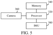
- FIG. 5 is a structural block diagram of an electronic device according to an exemplary embodiment of the present disclosure.
- the electronic device may be the first device 120 and/or the second device 140.
- the electronic device includes: a processor 320, a memory 340, a camera 360, and an IMU 380.
- the processor 320 includes one or more processing cores, which may be, for example, a 4-core processor or an 8-core processor.
- the processor 320 is configured to execute at least one of an instruction, code, a code snippet, and a program stored in the memory 340.
- the processor 320 is electrically connected to the memory 340. In some embodiments, the processor 320 is connected to the memory 340 by using a bus.
- the memory 340 stores one or more instructions, code, code snippets, and/or programs. The instruction, the code, the code snippet, and/or the program are/is executed by the processor 320 to implement a camera attitude tracking method provided in the following embodiments.
- the processor 320 is further electrically connected to the camera 360.
- the processor 320 is connected to the camera 360 by using a bus.
- the camera 360 is a sensing device having an image acquisition capability.
- the camera 360 may also be referred to as another name such as a camera component or a sensing device.
- the camera 360 has a capability of continuously acquiring images or acquiring images a plurality of times.
- the camera 360 is disposed inside the electronic device or outside the device.
- the processor 320 is further electrically connected to IMU 380.
- the IMU 380 is configured to collect an attitude vector of the camera at a pre-determined time interval, and record a timestamp of each set of attitude parameters during collection.
- the attitude parameters of the camera include a displacement vector and a rotation matrix.
- the rotation matrix collected by the IMU 380 is relatively accurate.
- the collected displacement vector may have a relatively large error caused by an actual environment.
- a specific form of the electronic device may be a smartphone, a tablet computer, AR glasses, an AR helmet, a portable notebook computer, an e-book reader, an MP3, an MP4, a handheld console, or the like. This is not limited in this embodiment of the present disclosure.
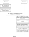
- FIG. 6 is a flowchart of a camera attitude tracking method according to an exemplary embodiment of the present disclosure. The method may be applied to the AR system shown in FIG. 1 or shown in FIG. 2 . The method includes the following steps:
- Step 401 The first device starts an AR scene initialization process.
- a target AR program supporting a multiplayer mode is run in the first device and the second device.
- the first device After the target AR program is started, for example, an AR scene or a round of an AR game is started, the first device performs an AR scene initialization process.
- the initialization process includes as follows:
- the initial attitude parameter is set by the user, or is set by the user by using the target AR program.
- a setting process of the initial attitude parameter may be explicitly perceived by the user, or may be explicitly unperceived by the user.
- the target AR program is a gaming program that superimposes virtual dolls in the real world.
- the image during superimposing the virtual doll is set as the initial image
- the attitude parameter during superimposing the virtual doll is set as the initial attitude parameter.
- the setting process is unperceived by the user.
- the first device performs a camera attitude tracking process according to the initial image and the initial attitude parameter.
- the first device performs a camera attitude tracking process according to the initial image and the initial attitude parameter.
- a camera attitude tracking technology the same as or similar to that a stand-alone form may be used in the camera attitude tracking process.
- Step 402. The first device records an initial image and an initial attitude parameter.
- Step 403. The first device transmits the initial image and the initial attitude parameter to the second device.
- the first device and the second device have the same target AR program installed.
- same target AR programs are installed in the first device and the second device, and a preset condition is met between the two target AR programs.
- the two target AR programs are logged in to by using respective accounts.
- the preset condition includes, but is not limited to, at least one of two user accounts being friends, two user accounts being in the same AR scene, two user accounts being in the same AR mode, and two user accounts being in the same AR game room.
- a target data channel is directly established between the first device and the second device.
- the first device transmits the initial image and the initial attitude parameter to the second device through the target data channel.
- the target data channel includes at least one of WiFi, Bluetooth, a wired network, and a data line.
- data between the first device and the second device needs to be forwarded through the server.
- the first device first transmits the initial image and the initial attitude parameter to the server, and the server forwards the initial image and the initial attitude parameter to the second device.
- Step 404 The second device receives the initial image and the initial attitude parameter that are transmitted by the first device.
- the second device receives the initial image and the initial attitude parameter that are transmitted by the first device through the target data channel or the server.
- the initial image is the first anchor image of the first device in the camera attitude tracking process.
- the initial attitude parameter is a camera attitude parameter corresponding to the first anchor image. Both the initial image and the initial attitude parameter are data generated by the first device, rather than data generated by the second device.
- Step 405. The second device obtains a current image acquired by a camera.
- a second camera is disposed in the second device. After the target AR program is started, the second camera continuously acquires frames of images in the real environment, and then transmits the images to a processor for processing.
- Step 406 The second device obtains a camera attitude variation of the current image relative to the initial image.
- the second device performs camera attitude tracking on the current image acquired by the second device relative to the initial image transmitted by the first device, and obtains, through calculation, the camera attitude variation of the current image relative to the initial image.
- the camera of the second device does not acquire the initial image.
- This step is performing camera attitude tracking by assuming the initial image to be an image acquired by the second device.
- the first device and the second device photograph the same real scene, for example, the same desktop. Therefore, images photographed by the first device and the second device are certainly correlated, and the initial image acquired by the first device may be assumed to be an image acquired by the second device for use.
- Step 407. The second device obtains, through calculation according to the initial attitude parameter and the camera attitude variation, a current camera attitude parameter used by the camera to acquire the current image.
- the second device obtains, through calculation according to the following formula, the camera attitude parameter including R and T used by the second camera to acquire the current image:
- R T 0 1 R cf T cf 0 1 ⁇ R born T born 0 1
- R cf being a rotation matrix in the camera attitude variation
- T cf being a displacement vector in the camera attitude variation
- R born being a rotation matrix in the initial attitude parameter
- T born being a displacement vector in the initial attitude parameter.
- the second device receives the initial image and the initial attitude parameter that are transmitted by the first device, calculates the camera attitude variation of the current image acquired by the camera of the second device relative to the initial image, and obtains, through calculation according to the initial attitude parameter and the camera attitude variation, the camera attitude parameter used by the camera to acquire the current image.
- the second device performs camera attitude tracking on the image acquired by the second device relative to the initial image of the first device, that is, the first device and the second device use the same initial image and initial attitude parameter to perform camera attitude tracking, which ensures that camera attitude tracking results of the first device and the second device are the same, thereby resolving a problem that a large amount of data needs to be transmitted if an environment map constructed on the first device needs to be synchronized to the second device.
- the steps performed by the first device may be separately implemented as a camera attitude tracking method on a first device side
- the steps performed by the second device may be separately implemented as a camera attitude tracking method on a second device side.
- the first device uses an anchor-switching AR system algorithm to perform camera attitude tracking.
- the anchor-switching AR system algorithm in a process of determining a camera attitude, an entire motion process of the first camera is divided into at least two tracking processes for tracking, and each tracking process corresponds to a respective anchor image.
- camera attitude tracking is first performed on a current image photographed by the camera based on the initial image (also referred to as the first anchor image).
- a camera attitude tracking process may include as follows: In a tracking process corresponding to an i th anchor image, when a tracking effect of the current image relative to the i th anchor image is worse than a preset condition (for example, a number of feature points that can be matched is less than a preset threshold), a previous image of the current image is determined as an (i+1) th anchor image, to start an (i+1) th tracking process, i being a positive integer.
- a preset condition for example, a number of feature points that can be matched is less than a preset threshold
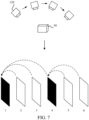
- the device determines the image 1 as an initial image (or an initial anchor) and records an initial attitude parameter.
- the initial attitude parameter may be an initial attitude parameter set by the user, or an attitude parameter used by the camera to acquire the image 1 and acquired by the IMU.
- feature point tracking is performed on the image 2 relative to the image 1, and an attitude parameter used by the camera to photograph the image 2 is calculated according to the initial attitude parameter and a feature point tracking result.
- Feature point tracking is performed on the image 3 relative to the image 1, and an attitude parameter used by the camera to photograph the image 3 is calculated according to the initial attitude parameter and a feature point tracking result.
- Feature point tracking is performed on the image 4 relative to the image 1, and an attitude parameter used by the camera to photograph the image 4 is calculated according to the initial attitude parameter and a feature point tracking result.
- feature point tracking is performed on the image 5 relative to the image 1. If a feature point tracking effect is worse than a preset condition (for example, a number of matched feature points is relatively small), the image 4 is determined as the second anchor image. Feature point tracking is performed on the image 5 relative to the image 4, a displacement variation of the camera between the image 4 and the image 5 during photographing is calculated, and then an attitude parameter used by the camera to photograph the image 5 is calculated with reference to the displacement variation of the camera between the image 4 and the image 1 during photographing and the initial attitude parameter. Then, feature point tracking is performed on the image 6 relative to the image 4. The rest can be done in the same manner. If a feature point tracking effect of a current image is poor, a previous frame of image of the current image may be determined as a new anchor image, and feature point tracking is re-performed based on the new anchor image.
- a preset condition for example, a number of matched feature points is relatively small
- the feature point tracking may use an algorithm based on a visual odometer principle, for example, a feature point method or a direct method.
- the second device after receiving the initial image and the initial attitude parameter, performs camera attitude tracking on a current image acquired by the second camera in the second device relative to the initial image. Assuming that the current image has different image acquisition timing and/or image content, this step may be implemented using at least one of the following two implementations.
- the second device relocates the current image relative to the initial image, to obtain a camera attitude variation.
- the second device obtains a first attitude variation of an i th anchor image relative to the initial image, i > 1, performs feature point tracking on the current image relative to the i th anchor image, to obtain a second attitude variation, and obtains the camera attitude variation through calculation according to the first attitude variation and the second attitude variation.
- the second device uses the first implementation to obtain a camera attitude variation of a current image relative to the initial image.
- the current image is one of the first few frames of images acquired by the second camera in the second device (or a loss occurs in a camera attitude tracking process)
- the second device sets the received initial image as the first anchor image of the second device, and the second device relocates the current image relative to the initial image, to obtain the camera attitude variation.
- the current image is switched (or set) to/as the second anchor image, and feature point tracking is performed on an image acquired after the current image relative to the second anchor image.
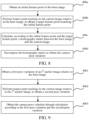
- Step 406 includes, but is not limited to, the following steps:
- Step 406a The second device obtains an initial feature point of the initial image.
- the second device when the first device transmits the initial image to the second device, and also transmits the initial feature point on the initial image, the second device directly reads the initial feature point of the initial image.
- the initial feature point is a feature point extracted from the initial image, and there may be a plurality of initial feature points, for example, 10 to 500 initial feature points.
- the second device extracts the initial feature point on the initial image.
- the first device may extract the feature point by using a feature extraction algorithm such as a features from accelerated segment test (FAST) detection algorithm, a Shi-Tomasi corner detection algorithm, a Harris corner detection algorithm, a scale-invariant feature transform (SIFT) algorithm, or an oriented FAST and rotated binary robust independent elementary feature (BRIEF) (ORB) algorithm.
- FAST accelerated segment test
- SIFT scale-invariant feature transform
- ORB binary robust independent elementary feature
- the device may extract an ORB feature point on the first anchor image.
- One ORB feature point includes two parts: a FAST corner (a key point) and a BRIEF descriptor. Because the ORB feature has a relatively fast calculation speed, the ORB feature is suitable for being implemented on a mobile device.
- the FAST corner refers to a position at which the ORB feature point is in an image.
- the FAST corner mainly detects a position at which a local pixel gray scale changes obviously, which is characterized by a high speed.
- the idea of the FAST corner is as follows: If a pixel differs greatly from (is excessively brighter or excessively darker than) an adjacent pixel, the pixel may be a corner.
- the BRIEF descriptor is a binary vector, which describes information about pixels around the key point in an artificial design manner.
- a description vector of the BRIEF descriptor includes a plurality of 0 and 1, and 0 and 1 herein encode a size relationship between two pixels near the FAST corner.
- Step 406b The second device performs feature point tracking on the current image relative to the initial image, to obtain a target feature point matching the initial feature point.
- the feature point tracking may use a tracking algorithm based on a visual odometer. This is not limited in the present disclosure.
- the feature point tracking uses Kanade-Lucas (KLT) optical flow tracking algorithm.
- the feature point tracking uses an ORB feature descriptor extracted based on the ORB algorithm.
- a specific algorithm for the feature point tracking is not limited in the present disclosure, and a feature point method or a direct method may be used in a feature point tracking process.
- the second device performs feature point extraction on the current image to obtain M candidate feature points, and then matches the M candidate feature points with N initial feature points one by one, to determine at least one matched feature point pair.
- Each matched feature point pair includes one initial feature point and one target feature point.
- the initial feature point is a feature point on the initial image
- the target feature point is a candidate feature point on the current image that matches the initial feature point at a highest degree.
- a number of initial feature points are greater than or equal to a number of target feature points.
- the number of initial feature points is 450, and there are 320 target feature points.
- Step 406c The second device calculates, according to the initial feature point and the target feature point, a homography matrix between the initial image and the current image.
- the homography matrix describes a mapping relationship between two imaging planes of the camera, that is, a mapping relationship between an imaging plane of the initial image and an imaging plane of the current image. If all feature points in a natural scene (a real environment) photographed on the two images fall on the same physical plane, the camera attitude motion estimation may be performed by using the homography matrix.
- Step 406d The second device decomposes the homography matrix to obtain the camera attitude variation.
- the device decomposes the homography matrix through ransac, to obtain the camera attitude variation.
- the camera attitude variation includes a rotation matrix R cf and a translation vector T cf .
- the second device may switch (or set) the current image to/as the second anchor image, and perform camera attitude tracking on other images acquired subsequently by the second camera relative to the second anchor image.
- the second device may switch (or set) the current image to/as the second anchor image, and perform camera attitude tracking on other images acquired subsequently by the second camera relative to the second anchor image.
- the second device relocates the current image relative to the initial image, to obtain the camera attitude variation through calculation.
- various information in a camera attitude tracking process can be constructed according to the current image acquired by the second device and the initial image acquired by the first device, and camera attitude tracking is performed using the same reference as the first device, thereby implementing synchronization of camera attitude tracking processes of an AR scene in a multiplayer mode.
- the second device uses the second implementation to obtain a camera attitude variation of a current image relative to the initial image. If the current image is an image acquired by the second device after a camera attitude tracking process is performed for a period of time, the second device has performed camera attitude tracking according to the anchor-switching AR system algorithm for the period of time. In this case, a camera attitude tracking process based on an i th anchor image is performed, i being an integer greater than 1.
- step 406 includes, but is not limited to, the following steps:
- Step 4061 The second device obtains a first attitude variation of the i th anchor image relative to the initial image, i > 1.
- the i th anchor image is the second anchor image, the third anchor image, the fourth anchor image, or the like. That is, the i th anchor image is an anchor image after the initial image.
- the i th anchor image is an image successfully tracked in a historical process.
- the first attitude variation of the i th anchor image relative to the initial image is buffered in the second device.
- the first attitude variation includes a first rotation matrix R mf and a first displacement vector T mf .
- Step 4062 The second device performs feature point tracking on the current image relative to the i th anchor image, to obtain a second attitude variation.
- the feature point tracking may use a tracking algorithm based on a visual odometer. This is not limited in the present disclosure.
- the feature point tracking uses a KLT optical flow tracking algorithm.
- the feature point tracking uses an ORB feature descriptor extracted based on the ORB algorithm.
- a specific algorithm for the feature point tracking is not limited in the present disclosure, and a feature point method or a direct method may be used in a feature point tracking process.
- this step includes the following sub-steps:
- the second device When setting the i th anchor image, the second device extracts N reference feature points of the i th anchor image.
- the second device When performing feature point tracking on the current image relative to the reference feature points of the i th anchor image, the second device performs feature point extraction on the current image, to obtain M candidate feature points, and then matches the M candidate feature points with the N reference feature points one by one, to determine at least one matched feature point pair.
- Each matched feature point pair includes one reference feature point and one target feature point.
- the reference feature point is a feature point on the i th anchor image
- the target feature point is a candidate feature point on the current image that matches the reference feature point at a highest degree.
- a number of reference feature points is greater than or equal to a number of target feature points.
- the number of reference feature points is 500, and there are 430 target feature points.
- the second device calculates, according to the reference feature point and the target feature point, a homography matrix between the i th anchor image and the current image.
- the homography matrix describes a mapping relationship between two imaging planes of the camera, that is, a mapping relationship between an imaging plane of the initial image and an imaging plane of the current image. If all feature points in a natural scene (a real environment) photographed on the two images fall on the same physical plane, camera attitude motion estimation may be performed by using the homography matrix.
- the second device decomposes the homography matrix to obtain a second attitude variation.
- the device decomposes the homography matrix through ransac, to obtain the second attitude variation.
- the second attitude variation includes a rotation matrix R cm and a translation vector T cm .
- Step 4063 The second device obtains the camera attitude variation through calculation according to the first attitude variation and the second attitude variation.
- S mf is a preset value, or S mf is a projected feature point obtained by mapping an initial feature point on the initial image to the i th anchor image, and the scale corresponding to the i th image is obtained through calculation according to an average depth of projected feature points.
- the second device after performing feature point tracking on the current image relative to the i th anchor image, the second device obtains the camera attitude variation through calculation using the first attitude variation and the second attitude variation, and obtains the current camera attitude parameter through calculation according to the camera attitude variation and the initial attitude parameter.
- various information in a camera attitude tracking process can be constructed according to the current image acquired by the second device and the initial image acquired by the first device, and camera attitude tracking is performed using the same reference as the first device, thereby implementing synchronization of camera attitude tracking processes of an AR scene in a multiplayer mode.
- a process of mapping, by the second device, an initial feature point on the first anchor image to the i th anchor image to obtain a projected feature point, and obtaining, through calculation, a scale corresponding to the i th anchor image according to an average depth of projected feature points is as follows:
- both the first device and the second device assume that a depth of the three-dimensional point corresponding to the initial image is 1, and use the same initial attitude parameter, three-dimensional worlds established by the first device and the second device with respect to the real world are definitely the same. Therefore, alignment of three-dimensional coordinate systems is directly implemented between the two devices.
- the camera attitude tracking method provided in this embodiment of the present disclosure can be applied to the field of AR, to track a motion attitude of a camera in a real environment during a motion process without prior information of the environment.
- Typical application scenarios are as follows:
- a plurality of devices are connected to the same game or game room.
- a first user uses any one of the devices to perform an initialization process to obtain an initial image and an initial attitude parameter, and then synchronizes the initial image and the initial attitude parameter to another device used by a second user.
- the another device performs camera attitude tracking based on the initial image and the initial attitude parameter.
- the plurality of devices finally implement the real-time multiplayer AR game based on the same camera tracking reference.
- AR-based treasure hunting game
- a first user buries a treasure (a virtual treasure) at a location A in the real world by using a first device.
- another user searches the location A for the treasure by using a second device, and may open and take away the treasure by using an AR program on the second device.
- the steps in the embodiments of the present disclosure are not necessarily performed in a sequence indicated by the step numbers. Unless clearly specified in this specification, there is no strict sequence limitation on the execution of the steps, and the steps may be performed in another sequence. Moreover, at least some of the steps in each embodiment may include a plurality of sub-steps or a plurality of stages. The sub-steps or stages are not necessarily performed at the same moment but may be performed at different moments. The sub-steps or stages are not necessarily performed sequentially, but may be performed in turn or alternately with another step or at least some of sub-steps or stages of the another step.
- an electronic device is further provided.
- An electronic device not forming part of the present invention includes a camera attitude tracking apparatus.
- the camera attitude tracking apparatus includes modules, and each module may be all or partially implemented by software, hardware, or a combination thereof.
- FIG. 10 is a block diagram of a camera attitude tracking apparatus which does not form part of the present invention.
- the apparatus may be implemented as a part of an electronic device (a second device) or as the device by software, hardware, or a combination of the two.
- the apparatus includes:
- the variation obtaining module 1060 is configured to relocate the current image relative to the initial image, to obtain the camera attitude variation, and/or the variation obtaining module 1060 is configured to: obtain a first attitude variation of an i th anchor image relative to the initial image, i > 1; perform feature point tracking on the current image relative to the i th anchor image, to obtain a second attitude variation; and obtain the camera attitude variation through calculation according to the first attitude variation and the second attitude variation.
- the variation obtaining module 1060 is configured to: obtain an initial feature point of the initial image; perform feature point tracking on the current image relative to the initial image, to obtain a target feature point matching the initial feature point; calculate, according to the initial feature point and the target feature point, a homography matrix between the initial image and the current image; and decompose the homography matrix to obtain the camera attitude variation.
- the receiving module 1020 is configured to receive the initial image and the initial attitude parameter that are transmitted by the first device through a target data channel, the target data channel including at least one of a WiFi network, Bluetooth, a wired network, and a data line; and/or the receiving module 1020 is configured to receive the initial image and the initial attitude parameter that are transmitted by a server, the initial image and the initial attitude parameter being transmitted to the server by the first device.
- the foregoing functional module For camera attitude tracking performed by the camera attitude tracking apparatus provided in the foregoing embodiment, only division of the foregoing functional module is used as an example for description. During actual application, the foregoing functions may be allocated to and completed by different functional modules according to requirements, that is, the internal structure of the device is divided into different functional modules, to complete all or some of the foregoing described functions.
- the camera attitude tracking apparatus provided in the foregoing embodiments and the camera attitude tracking method embodiments fall within the same conception. For a specific implementation process of the camera attitude tracking apparatus, refer to the method embodiments.
- FIG. 11 is a structural block diagram of a terminal 1100 according to an exemplary embodiment of the present disclosure.
- the terminal 1100 may be a smartphone, a tablet computer, an MP3 player, an MP4 player, a notebook computer, or a desktop computer.
- the terminal 1100 may also be referred to as other names such as a user device, a portable terminal, a laptop computer, or a desktop terminal.
- the terminal 1100 includes a processor 1101 and a memory 1102.
- the processor 1101 may include one or more processing cores, which may be, for example, a 4-core processor or an 8-core processor.
- the processor 1101 may be implemented in at least one hardware form of a digital signal processor (DSP), a field programmable gate array (FPGA), and a programmable logic array (PLA).
- the processor 1101 may also include a main processor and a coprocessor.
- the main processor is a processor configured to process data in an active state, which is also referred to as a central processing unit (CPU).
- the coprocessor is a low power consumption processor configured to process data in a standby state.
- the processor 1101 may be integrated with a graphics processing unit (GPU).
- the GPU is configured to be responsible for rendering and drawing content that a display screen needs to display.
- the processor 1101 may further include an artificial intelligence (AI) processor.
- the AI processor is configured to process a computing operation related to machine learning.
- the memory 1102 may include one or more computer-readable storage media.
- the computer-readable storage medium may be non-transient.
- the memory 1102 may further include a high-speed random access memory (RAM) and a nonvolatile memory, for example, one or more disk storage devices or flash memory devices.
- RAM random access memory
- the non-transitory computer-readable storage medium in the memory 1102 is configured to store at least one instruction.
- the at least one instruction is configured to be executed by the processor 1101 to implement the camera attitude tracking method provided in the method embodiment of the present disclosure.
- the terminal 1100 may optionally further include: a peripheral device interface 1103 and at least one peripheral device.
- the processor 1101 and the memory 1102 may be connected to the peripheral device interface 1103 by using a bus or a signal line.
- the peripheral devices may be connected to the peripheral device interface 1103 by using a bus, a signal line, or a circuit board.
- the peripheral device includes at least one of a radio frequency (RF) circuit 1104, a display screen 1105, a camera component 1106, an audio circuit 1107, a positioning component 1108, and a power supply 1109.
- RF radio frequency
- the peripheral device interface 1103 may be configured to connect at least one input/output (I/O)-related peripheral device to the processor 1101 and the memory 1102.
- the processor 1101, the memory 1102 and the peripheral device interface 1103 are integrated on the same chip or circuit board.
- any one or two of the processor 1101, the memory 1102, and the peripheral device interface 1103 may be implemented on a single chip or circuit board. This is not limited in this embodiment.
- the RF circuit 1104 is configured to receive and transmit an RF signal, which is also referred to as an electromagnetic signal.
- the RF circuit 1104 communicates with a communications network and other communications devices by using the electromagnetic signal.
- the RF circuit 1104 may convert an electric signal into an electromagnetic signal for transmission, or convert a received electromagnetic signal into an electric signal.
- the RF circuit 1104 includes an antenna system, an RF transceiver, one or more amplifiers, a tuner, an oscillator, a digital signal processor, a codec chip set, a subscriber identity module card, and the like.
- the RF circuit 1104 may communicate with other terminals through at least one wireless communication protocol.
- the wireless communication protocol includes, but is not limited to: a world wide web, a metropolitan area network, an intranet, (2G, 3G, 4G, and 5G) mobile communication networks, a wireless local area network, and/or a WiFi network.
- the RF circuit 1104 may also include a circuit related to near field communication (NFC). This is not limited in the present disclosure.
- the display screen 1105 is configured to display a user interface (UI).
- the UI may include a graph, a text, an icon, a video, and any combination thereof.
- the display screen 1105 is a touchscreen, the display screen 1105 is further capable of collecting a touch signal on or over a surface of the display screen 1105.
- the touch signal may be inputted into the processor 1101 as a control signal for processing.
- the display screen 1105 may be further configured to provide a virtual button and/or a virtual keyboard, also referred to as a soft button and/or a soft keyboard.
- the display screen 1105 may be a flexible display screen, disposed on a curved surface or a folded surface of the terminal 1100. Even, the display screen 1105 may be further set to have a non-rectangular irregular graph, that is, a special-shaped screen.
- the display screen 1105 may be manufactured by using a material such as a liquid crystal display (LCD) or an organic light-emitting diode (OLED).
- the camera component 1106 is configured to acquire an image or a video.
- the camera component 1106 includes a front-facing camera and a rear-facing camera.
- the front-facing camera is disposed on the front panel of the terminal
- the rear-facing camera is disposed on a back face of the terminal.
- there are at least two rear-facing cameras each being any one of a main camera, a depth of field camera, a wide-angle camera, and a telephoto camera, to implement a Bokeh function through fusion of the main camera and the depth of field camera, panoramic photo shooting and virtual reality (VR) shooting functions through fusion of the main camera and wide-angle camera, or another fusion shooting function.
- VR virtual reality
- the camera component 1106 may further include a flash.
- the flash may be a single color temperature flash, or may be a double color temperature flash.
- the double color temperature flash refers to a combination of a warm flash and a cold flash, and may be used for light compensation at different color temperatures.
- the audio circuit 1107 may include a microphone and a speaker.
- the microphone is configured to: collect sound waves of a user and an environment, and convert the sound waves into the electric signals to be inputted to the processor 1101 for processing, or to be inputted to the RF circuit 1104 for implementing speech communication.
- the microphone may be further an array microphone or an omni-directional collection type microphone.
- the speaker is configured to convert the electric signals from the processor 1101 or the RF circuit 1104 into the sound waves.
- the speaker may be a conventional thin-film speaker, or may be a piezoelectric ceramic speaker.
- the electric signals not only can be converted into the sound waves audible to a human being, but also can be converted into the sound waves inaudible to the human being for ranging and the like.
- the audio circuit 1107 may further include an earphone jack.
- the positioning component 1108 is configured to position a current geographic location of the terminal 1100, to implement a navigation or a location based service (LBS).
- the positioning component 1108 may be a positioning component based on the global positioning system (GPS) of the United States, the COMPASS System of China, or the Galileo system of Russia.
- GPS global positioning system
- the power supply 1109 is configured to supply power for components in the terminal 1100.
- the power supply 1109 may be an alternating current, a direct current, a primary battery, or a rechargeable battery.
- the rechargeable battery may be a wired charging battery or a wireless charging battery.
- the wired charging battery is a battery charged through a wired line
- the wireless charging battery is a battery charged through a wireless coil.
- the rechargeable battery may be further configured to support a quick charge technology.
- the terminal 1100 further includes one or more sensors 1110.
- the one or more sensors 1110 include, but are not limited to, an acceleration sensor 1111, a gyroscope sensor 1112, a pressure sensor 1113, a fingerprint sensor 1114, an optical sensor 1115, and a proximity sensor 1111.
- the acceleration sensor 1111 may detect acceleration on three coordinate axes of a coordinate system established by the terminal 1100.
- the acceleration sensor 1111 may be configured to detect a component of gravity acceleration on the three coordinate axes.
- the processor 1101 may control, according to a gravity acceleration signal collected by the acceleration sensor 1111, the display screen 1105 to display the UI in a frame view or a longitudinal view.
- the acceleration sensor 1111 may be further configured to collect game or user motion data.
- the gyroscope sensor 1112 may detect a body direction and a rotation angle of the terminal 1100.
- the gyroscope sensor 1112 may cooperate with the acceleration sensor 1111 to collect a 3D action by the user on the terminal 1100.
- the processor 1101 may implement the following functions according to the data collected by the gyroscope sensor 1112: motion sensing (such as changing the UI according to a tilt operation of the user), image stabilization at shooting, game control, and inertial navigation.
- the pressure sensor 1113 may be disposed at a side frame of the terminal 1100 and/or a lower layer of the display screen 1105.
- a holding signal of the user to the terminal 1100 may be detected, and the processor 1101 performs left/right hand identification and a quick action according to the holding signal collected by the pressure sensor 1113.
- the processor 1101 controls an operable control on the UI interface according to a pressure operation of the user on the display screen 1105.
- the operable control includes at least one of a button control, a scroll-bar control, an icon control, and a menu control.
- the fingerprint sensor 1114 is configured to collect a user's fingerprint.
- the processor identifies a user's identity according to the fingerprint collected by the fingerprint sensor 1114, or identifies the user's identity according to the fingerprint collected by the fingerprint sensor 1114.
- the processor 1101 authorizes the user to perform related sensitive operations.
- the sensitive operations includes: unlocking a screen, viewing encryption information, downloading software, paying and changing a setting, and the like.
- the fingerprint sensor 1114 may be disposed on a front surface, a back surface, or a side surface of the terminal 1100. When a physical button or a vendor logo is disposed on the terminal 1100, the fingerprint sensor 1114 may be integrated with the physical button or the vendor logo.
- the optical sensor 1115 is configured to collect ambient light intensity.
- the processor 1101 may control the display brightness of the display screen 1105 according to the ambient light intensity collected by the optical sensor 1115. Specifically, when the ambient light intensity is relatively high, the display brightness of the display screen 1105 is turned up. When the ambient light intensity is relatively low, the display brightness of the display screen 1105 is turned down.
- the processor 1101 may further dynamically adjust a camera parameter of the camera component 1106 according to the ambient light intensity collected by the optical sensor 1115.
- the proximity sensor 1116 also referred to as a distance sensor, is generally disposed on the front panel of the terminal 1100.
- the proximity sensor 1116 is configured to collect a distance between the user and the front surface of the terminal 1100.
- the display screen 1105 is controlled by the processor 1101 to switch from a bright screen state to an on-screen state.
- the display screen 1105 is controlled by the processor 1101 to switch from the on-screen state to the bright screen state.
- FIG. 11 constitutes no limitation on the terminal 1100, and the terminal may include more or fewer components than those shown in the figure, or some components may be combined, or a different component deployment may be used.
- FIG. 12 is a diagram of an internal structure of an electronic device according to an embodiment not forming part of the present invention.
- the electronic device includes a processor, a memory, a network interface, and an input apparatus that are connected by using a system bus.
- the memory includes a non-volatile storage medium and an internal memory.
- the non-volatile storage medium of the electronic device stores an operating system, and may further store computer-readable instructions, the computer-readable instructions, when executed by the processor, causing the processor to perform the camera attitude tracking method.
- the internal memory may also store computer-readable instructions, and the computer-readable instructions, when executed by the processor, causing the processor to perform the camera attitude tracking method.
- the input device may be a touch layer covering a display screen, or may be a button, a trackball, or a touch panel disposed on a housing of the electronic device, or may be an external keyboard, a touch panel, or a mouse.
- FIG. 12 is only a block diagram of a partial structure related to the solution of the present disclosure, and does not constitute a limitation to the electronic device to which the solution of the present disclosure is applied.
- the electronic device may include more or fewer components than those shown in the figure, or some components may be combined, or a different component deployment may be used.
- the camera attitude tracking apparatus may be implemented in a form of a computer-readable instruction, and the computer-readable instruction may run on the electronic device shown in FIG. 12 .
- the memory of the electronic device may store program modules forming the camera attitude tracking apparatus, for example, the receiving module 1020, the image obtaining module 1040, the variation obtaining module 1060, and the attitude calculating module 1080 shown in FIG. 10 .
- the computer-readable instruction formed by the program modules causes the processor to perform the steps in the camera attitude tracking method in the embodiments of the present disclosure described in this specification.
- An embodiment of the present disclosure provides a computer-readable storage medium.
- the storage medium stores computer-readable instructions, the computer-readable instructions being loaded and executed by a processor to implement the camera attitude tracking method shown in FIG. 6 .
- the non-volatile memory may include a read-only memory (ROM), a programmable ROM (PROM), an electrically programmable ROM (EPROM), an electrically erasable programmable ROM (EEPROM), a flash memory, or the like.
- ROM read-only memory
- PROM programmable ROM
- EPROM electrically programmable ROM
- EEPROM electrically erasable programmable ROM
- the volatile memory may include a RAM or an external cache.
- the RAM is available in various forms, such as a static RAM (SRAM), a dynamic RAM (DRAM), a synchronous DRAM (SDRAM), a double data rate SDRAM (DDRSDRAM), an enhanced SDRAM (ESDRAM), a synchronization link (Synchlink) DRAM (SLDRAM), a rambus direct RAM (RDRAM), a direct rambus dynamic RAM (DRDRAM), and a rambus dynamic RAM (RDRAM).
- SRAM static RAM
- DRAM dynamic RAM
- SDRAM synchronous DRAM
- DDRSDRAM double data rate SDRAM
- ESDRAM enhanced SDRAM
- SLDRAM synchronization link
- RDRAM rambus direct RAM
- DRAM direct rambus dynamic RAM
- RDRAM rambus dynamic RAM
Landscapes
- Engineering & Computer Science (AREA)
- Theoretical Computer Science (AREA)
- Physics & Mathematics (AREA)
- General Physics & Mathematics (AREA)
- Computer Vision & Pattern Recognition (AREA)
- General Engineering & Computer Science (AREA)
- Multimedia (AREA)
- Computer Hardware Design (AREA)
- Software Systems (AREA)
- Computer Graphics (AREA)
- Human Computer Interaction (AREA)
- Studio Devices (AREA)
- User Interface Of Digital Computer (AREA)
- Image Analysis (AREA)
Claims (10)
- Computer-implementiertes Verfahren zum Verfolgen einer Kamerastellung, das von einer zweiten Vorrichtung mit einer Kamera durchgeführt wird, wobei das Verfahren umfasst:Empfangen (404) eines anfänglichen Bildes und eines anfänglichen Einstellungsparameters, die von einer ersten Vorrichtung übertragen werden, durch die zweite Vorrichtung, wobei das anfängliche Bild ein erstes Ankerbild der ersten Vorrichtung in einem Kameraeinstellungsverfolgungsprozess ist und der anfängliche Einstellungsparameter ein Kameraeinstellungsparameter ist, der dem ersten Ankerbild entspricht;Erhalten (405), durch die zweite Vorrichtung, eines aktuellen Bildes, das von der Kamera der zweiten Vorrichtung aufgenommen wurde;Erhalten (406), durch die zweite Vorrichtung, einer Kameraeinstellungsänderung des aktuellen Bildes relativ zu dem Ausgangsbild, was Durchführen einer Kameraeinstellungsnachführung an dem aktuellen Bild relativ zu dem Ausgangsbild und das Erhalten, durch Berechnung, der Kameraeinstellungsänderung des aktuellen Bildes relativ zu dem Ausgangsbild enthält; unddadurch gekennzeichnet, dass das Verfahren ferner umfasst:
Erhalten (407) eines aktuellen Kameraeinstellungsparameters, der dem aktuellen Bild entspricht, durch die zweite Vorrichtung, durch Berechnen gemäß dem anfänglichen Einstellungsparameter und der Kameraeinstellungsänderung, umfassend:
Berechnen einer Rotationsmatrix in dem aktuellen Kameraeinstellungsparameter und eines Verschiebungsvektors in dem aktuellen Kameraeinstellungsparameter gemäß: einer Rotationsmatrix in der Kameraeinstellungsänderung, einem Verschiebungsvektor in der Kameraeinstellungsänderung, einer Rotationsmatrix in dem ursprünglichen Einstellungsparameter und einem Verschiebungsvektor in dem ursprünglichen Einstellungsparameter . - Verfahren gemäß Anspruch 1, wobei das Ermitteln der Änderung der Kameraeinstellung des aktuellen Bildes relativ zum Ausgangsbild durch die zweite Vorrichtung umfasst:
Verschieben des aktuellen Bildes relativ zum Ausgangsbild durch die zweite Vorrichtung, um die Änderung der Kameraeinstellung zu erhalten. - Verfahren gemäß Anspruch 1, wobei das Ermitteln der Änderung der Kameraeinstellung des aktuellen Bildes relativ zum Ausgangsbild durch die zweite Vorrichtung umfasst:Erhalten durch die zweite Vorrichtung einer ersten Einstellungsänderung eines iten Ankerbildes gegenüber dem Ausgangsbild, i > 1;Durchführen einer Merkmalspunktverfolgung auf dem aktuellen Bild relativ zu dem iten Ankerbild durch die zweite Vorrichtung, um eine zweite Einstellungsänderung zu erhalten; undErmitteln der Einstellungsänderung der Kamera durch die zweite Vorrichtung durch Berechnen gemäß der ersten Einstellungsänderung und der zweiten Einstellungsänderung.
- Verfahren nach Anspruch 2 oder 3, wobei das Verschieben des aktuellen Bildes relativ zum Ausgangsbild durch die zweite Vorrichtung, um die Änderung der Kameraeinstellung zu erhalten, umfasst:Erhalten (406a), durch die zweite Vorrichtung, eines anfänglichen Merkmalspunktes des Anfangsbildes;Durchführen (406b) einer Merkmalspunktverfolgung auf dem aktuellen Bild relativ zum Ausgangsbild durch die zweite Vorrichtung, um einen Zielmerkmalspunkt zu erhalten, der mit dem Ausgangsmerkmalspunkt übereinstimmt;Berechnen (406c) einer Homographiematrix zwischen dem Ausgangsbild und dem aktuellen Bild durch die zweite Vorrichtung gemäß dem Ausgangsmerkmalspunkt und dem Zielmerkmalspunkt; undZerlegen (406d) der Homographie-Matrix durch die zweite Vorrichtung, um die Kameraeinstellungsänderung zu erhalten.
- Verfahren nach Anspruch 2 oder 3, wobei das Erhalten der Kameraeinstellungsänderung durch die zweite Vorrichtung durch Berechnen gemäß der ersten Einstellungsänderung und der zweiten Einstellungsänderung umfasst:
Erhalten der Kameraeinstellungsänderung, die Rcf und Tcf umfasst, durch Berechnen gemäß der folgenden Formel, unter der Annahme, dass die erste Einstellungsänderung eine erste Rotationsmatrix Rmf und einen ersten Verschiebungsvektor Tmf umfasst, und die zweite Einstellungsänderung eine zweite Rotationsmatrix Rcm und einen zweiten Verschiebungsvektor Tcm umfasst: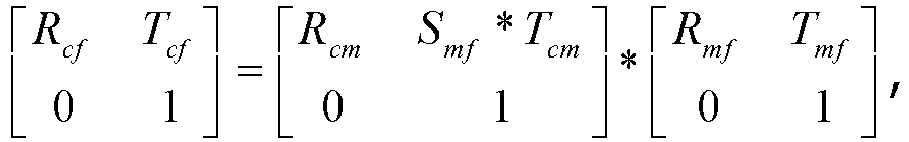
- Verfahren gemäß einem der Ansprüche 1 bis 5, wobei das Erhalten des aktuellen Kameraeinstellungsparameters, der dem aktuellen Bild entspricht, durch die zweite Vorrichtung auf der Grundlage des anfänglichen Einstellungsparameters und der Kameraeinstellungsänderung umfasst:
Ermitteln des R und T umfassenden Kameraeinstellungsparameters durch Berechnen nach der folgenden Formel:
- Verfahren nach einem der Ansprüche 1 bis 5, wobei das Empfangen des Ausgangsbildes und des Ausgangseinstellungsparameters durch die zweite Vorrichtung, die von der ersten Vorrichtung übertragen werden, umfasst:
Empfangen des Ausgangsbildes und des Ausgangseinstellungsparameters, die von der ersten Vorrichtung über einen Zieldatenkanal übertragen werden, durch die zweite Vorrichtung, wobei der Zieldatenkanal mindestens ein drahtloses Fidelity-Netzwerk (WiFi), Bluetooth, ein drahtgebundenes Netzwerk oder eine Datenleitung umfasst. - Verfahren nach einem der Ansprüche 1 bis 5, wobei das Empfangen des Ausgangsbildes und des Ausgangseinstellungsparameters, die von einer ersten Vorrichtung übertragen werden, durch die zweite Vorrichtung umfasst:
Empfangen des Ausgangsbildes und des Ausgangseinstellungsparameters, die von einem Server übertragen werden, durch die zweite Vorrichtung, wobei das Ausgangsbild und der Ausgangseinstellungsparameter von der ersten Vorrichtung an den Server übertragen werden. - Elektronische Vorrichtung, die umfasst:einen Prozessor, undeinen Speicher, der computerlesbare Befehle speichert, die, wenn sie von dem Prozessor ausgeführt werden, den Prozessor veranlassen, das Verfahren zur Verfolgung der Kameraeinstellung gemäß einem der Ansprüche 1 bis 8 durchzuführen.
- Ein oder mehrere nicht transitorische Speichermedien, auf denen computerlesbare Befehle gespeichert sind, wobei die computerlesbaren Befehle, wenn sie von einem oder mehreren Prozessoren ausgeführt werden, den einen oder die mehreren Prozessoren veranlassen, das Verfahren zur Verfolgung der Kameraeinstellung gemäß einem der Ansprüche 1 bis 8 durchzuführen.
Applications Claiming Priority (2)
| Application Number | Priority Date | Filing Date | Title |
|---|---|---|---|
| CN201810495056.7A CN108734736B (zh) | 2018-05-22 | 2018-05-22 | 相机姿态追踪方法、装置、设备及存储介质 |
| PCT/CN2019/083437 WO2019223468A1 (zh) | 2018-05-22 | 2019-04-19 | 相机姿态追踪方法、装置、设备及系统 |
Publications (3)
| Publication Number | Publication Date |
|---|---|
| EP3798983A1 EP3798983A1 (de) | 2021-03-31 |
| EP3798983A4 EP3798983A4 (de) | 2021-07-21 |
| EP3798983B1 true EP3798983B1 (de) | 2024-02-07 |
Family
ID=63937866
Family Applications (1)
| Application Number | Title | Priority Date | Filing Date |
|---|---|---|---|
| EP19808400.6A Active EP3798983B1 (de) | 2018-05-22 | 2019-04-19 | Verfahren und gerät, vorrichtung sowie system zur kameraausrichtungsverfolgung |
Country Status (4)
| Country | Link |
|---|---|
| US (1) | US11321870B2 (de) |
| EP (1) | EP3798983B1 (de) |
| CN (2) | CN108734736B (de) |
| WO (1) | WO2019223468A1 (de) |
Families Citing this family (35)
| Publication number | Priority date | Publication date | Assignee | Title |
|---|---|---|---|---|
| CN108734736B (zh) | 2018-05-22 | 2021-10-26 | 腾讯科技(深圳)有限公司 | 相机姿态追踪方法、装置、设备及存储介质 |
| CN109544615B (zh) * | 2018-11-23 | 2021-08-24 | 深圳市腾讯信息技术有限公司 | 基于图像的重定位方法、装置、终端及存储介质 |
| CN109992111B (zh) * | 2019-03-25 | 2021-02-19 | 联想(北京)有限公司 | 增强现实扩展方法和电子设备 |
| CN109847350A (zh) * | 2019-03-25 | 2019-06-07 | 深圳初影科技有限公司 | 基于ar技术的游戏实现方法、游戏系统、及存储介质 |
| CN109908589B (zh) * | 2019-03-25 | 2022-09-02 | 深圳初影科技有限公司 | 基于ar技术的游戏实现方法、游戏系统、及存储介质 |
| CN110286768B (zh) * | 2019-06-27 | 2022-05-17 | Oppo广东移动通信有限公司 | 虚拟物体显示方法、终端设备及计算机可读存储介质 |
| CN110276794B (zh) * | 2019-06-28 | 2022-03-01 | Oppo广东移动通信有限公司 | 信息处理方法、信息处理装置、终端设备及服务器 |
| CN110473259A (zh) * | 2019-07-31 | 2019-11-19 | 深圳市商汤科技有限公司 | 位姿确定方法及装置、电子设备和存储介质 |
| CN110989825B (zh) * | 2019-09-10 | 2020-12-01 | 中兴通讯股份有限公司 | 增强现实互动实现方法及系统、增强现实设备、存储介质 |
| CN110866977B (zh) * | 2019-10-31 | 2023-06-16 | Oppo广东移动通信有限公司 | 增强现实处理方法及装置、系统、存储介质和电子设备 |
| CN111078003B (zh) | 2019-11-27 | 2021-10-22 | Oppo广东移动通信有限公司 | 数据处理方法、装置、电子设备及存储介质 |
| CN111179435B (zh) * | 2019-12-24 | 2024-02-06 | Oppo广东移动通信有限公司 | 增强现实处理方法及装置、系统、存储介质和电子设备 |
| CN111338474B (zh) * | 2020-02-19 | 2022-11-08 | Oppo广东移动通信有限公司 | 虚拟对象位姿校准方法及装置、存储介质和电子设备 |
| CN112083867A (zh) | 2020-07-29 | 2020-12-15 | 华为技术有限公司 | 一种跨设备的对象拖拽方法及设备 |
| CN113781548B (zh) * | 2020-06-10 | 2024-06-14 | 华为技术有限公司 | 多设备的位姿测量方法、电子设备及系统 |
| CN114115629B (zh) | 2020-08-26 | 2025-01-10 | 华为技术有限公司 | 一种界面显示方法及设备 |
| CN111582385B (zh) * | 2020-05-11 | 2023-10-31 | 杭州易现先进科技有限公司 | Slam质量的量化方法、系统、计算机设备和存储介质 |
| CN111798489B (zh) * | 2020-06-29 | 2024-03-08 | 北京三快在线科技有限公司 | 一种特征点跟踪方法、设备、介质及无人设备 |
| CN117971104A (zh) | 2020-07-29 | 2024-05-03 | 华为技术有限公司 | 一种跨设备的对象拖拽方法及设备 |
| CN111897429B (zh) * | 2020-07-30 | 2025-08-26 | 腾讯科技(深圳)有限公司 | 图像显示方法、装置、计算机设备及存储介质 |
| CN112242008B (zh) * | 2020-10-17 | 2021-09-07 | 郑州西亚斯学院 | 一种用于透明容器的ar交互视觉感知方法及系统 |
| CN112650422B (zh) * | 2020-12-17 | 2022-07-29 | 咪咕文化科技有限公司 | 设备的ar交互方法、装置、电子设备及存储介质 |
| CN112767455B (zh) * | 2021-01-08 | 2022-09-02 | 合肥的卢深视科技有限公司 | 一种双目结构光的校准方法及系统 |
| CN114812381B (zh) * | 2021-01-28 | 2023-07-18 | 华为技术有限公司 | 电子设备的定位方法及电子设备 |
| CN114827338A (zh) * | 2021-01-29 | 2022-07-29 | 北京外号信息技术有限公司 | 用于在设备的显示媒介上呈现虚拟对象的方法和电子装置 |
| CN114088062B (zh) * | 2021-02-24 | 2024-03-22 | 上海商汤临港智能科技有限公司 | 目标定位方法及装置、电子设备和存储介质 |
| US11961201B2 (en) * | 2021-05-21 | 2024-04-16 | Meta Platforms Technologies, Llc | Viewing 3D photo galleries in VR |
| CN113223007A (zh) * | 2021-06-28 | 2021-08-06 | 浙江华睿科技股份有限公司 | 视觉里程计的实现方法、装置及电子设备 |
| CN115705116A (zh) * | 2021-08-04 | 2023-02-17 | 北京字跳网络技术有限公司 | 交互方法、电子设备、存储介质和程序产品 |
| CN118230203B (zh) | 2021-09-08 | 2025-04-18 | 荣耀终端股份有限公司 | Ar翻译的处理方法及电子设备 |
| CN114898084B (zh) * | 2022-04-18 | 2023-08-25 | 荣耀终端有限公司 | 视觉定位方法、设备和存储介质 |
| US12299897B2 (en) * | 2022-05-09 | 2025-05-13 | Htc Corporation | Virtual reality system, control method, and non-transitory computer readable storage medium |
| CN119452330A (zh) * | 2022-09-21 | 2025-02-14 | 海信电子科技(深圳)有限公司 | 一种估计手柄位姿的方法及虚拟显示设备 |
| CN115826808A (zh) * | 2022-11-11 | 2023-03-21 | 北京理工大学 | 一种基于增强现实的手工装配过程干涉性检验系统及方法 |
| CN116246084A (zh) * | 2023-02-15 | 2023-06-09 | 福建汇川物联网技术科技股份有限公司 | 一种边坡的监测方法、装置、电子设备及存储介质 |
Citations (2)
| Publication number | Priority date | Publication date | Assignee | Title |
|---|---|---|---|---|
| WO2016078728A1 (en) * | 2014-11-21 | 2016-05-26 | Metaio Gmbh | Method and system for determining spatial coordinates of a 3d reconstruction of at least part of a real object at absolute spatial scale |
| US20170323458A1 (en) * | 2013-03-15 | 2017-11-09 | Peter Lablans | Camera for Locating Hidden Objects |
Family Cites Families (30)
| Publication number | Priority date | Publication date | Assignee | Title |
|---|---|---|---|---|
| JP4991395B2 (ja) * | 2007-05-28 | 2012-08-01 | キヤノン株式会社 | 情報処理方法及び情報処理装置 |
| US9020187B2 (en) * | 2011-05-27 | 2015-04-28 | Qualcomm Incorporated | Planar mapping and tracking for mobile devices |
| US9524555B2 (en) * | 2011-12-12 | 2016-12-20 | Beihang University | Method and computer program product of the simultaneous pose and points-correspondences determination from a planar model |
| AU2011253973B2 (en) * | 2011-12-12 | 2015-03-12 | Canon Kabushiki Kaisha | Keyframe selection for parallel tracking and mapping |
| JP5872923B2 (ja) * | 2012-02-22 | 2016-03-01 | 株式会社マイクロネット | Ar画像処理装置及び方法 |
| CN103971400B (zh) | 2013-02-06 | 2018-02-02 | 阿里巴巴集团控股有限公司 | 一种基于标识码的三维交互的方法和系统 |
| US9846942B2 (en) * | 2013-10-09 | 2017-12-19 | Apple Inc. | Method and system for determining a pose of camera |
| CN106664393A (zh) * | 2014-07-31 | 2017-05-10 | 索尼公司 | 信息处理装置、信息处理方法以及图像显示系统 |
| US20160133230A1 (en) * | 2014-11-11 | 2016-05-12 | Bent Image Lab, Llc | Real-time shared augmented reality experience |
| CN106296598B (zh) * | 2016-07-29 | 2019-11-26 | 厦门美图之家科技有限公司 | 三维姿态处理方法、系统及拍摄终端 |
| CN106843456B (zh) * | 2016-08-16 | 2018-06-29 | 深圳超多维光电子有限公司 | 一种基于姿态追踪的显示方法、装置和虚拟现实设备 |
| EP3296950A1 (de) | 2016-09-15 | 2018-03-21 | Thomson Licensing | Verfahren und vorrichtung zur verwischung eines virtuellen objekts in einem video |
| JP2018055589A (ja) * | 2016-09-30 | 2018-04-05 | セイコーエプソン株式会社 | プログラム、物体の追跡方法、表示装置 |
| CN108022264B (zh) * | 2016-11-01 | 2023-06-13 | 北京墨土科技有限公司 | 相机位姿确定方法及设备 |
| CN106780601B (zh) * | 2016-12-01 | 2020-03-27 | 北京未动科技有限公司 | 一种空间位置追踪方法、装置及智能设备 |
| CN106873784A (zh) * | 2017-03-29 | 2017-06-20 | 联想(北京)有限公司 | 一种显示控制方法、装置及电子设备 |
| GB2561368B (en) * | 2017-04-11 | 2019-10-09 | Nokia Technologies Oy | Methods and apparatuses for determining positions of multi-directional image capture apparatuses |
| CN107194968B (zh) * | 2017-05-18 | 2024-01-16 | 腾讯科技(上海)有限公司 | 图像的识别跟踪方法、装置、智能终端和可读存储介质 |
| CN107590453B (zh) | 2017-09-04 | 2019-01-11 | 腾讯科技(深圳)有限公司 | 增强现实场景的处理方法、装置及设备、计算机存储介质 |
| US10515458B1 (en) * | 2017-09-06 | 2019-12-24 | The United States Of America, As Represented By The Secretary Of The Navy | Image-matching navigation method and apparatus for aerial vehicles |
| CN108596976B (zh) | 2018-04-27 | 2022-02-22 | 腾讯科技(深圳)有限公司 | 相机姿态追踪过程的重定位方法、装置、设备及存储介质 |
| CN108615248B (zh) | 2018-04-27 | 2022-04-05 | 腾讯科技(深圳)有限公司 | 相机姿态追踪过程的重定位方法、装置、设备及存储介质 |
| CN108615247B (zh) | 2018-04-27 | 2021-09-14 | 深圳市腾讯计算机系统有限公司 | 相机姿态追踪过程的重定位方法、装置、设备及存储介质 |
| CN110555882B (zh) | 2018-04-27 | 2022-11-15 | 腾讯科技(深圳)有限公司 | 界面显示方法、装置及存储介质 |
| CN108682038B (zh) | 2018-04-27 | 2021-12-14 | 腾讯科技(深圳)有限公司 | 位姿确定方法、装置及存储介质 |
| CN110599549B (zh) | 2018-04-27 | 2023-01-10 | 腾讯科技(深圳)有限公司 | 界面显示方法、装置及存储介质 |
| CN108876854B (zh) | 2018-04-27 | 2022-03-08 | 腾讯科技(深圳)有限公司 | 相机姿态追踪过程的重定位方法、装置、设备及存储介质 |
| CN110555883B (zh) | 2018-04-27 | 2022-07-22 | 腾讯科技(深圳)有限公司 | 相机姿态追踪过程的重定位方法、装置及存储介质 |
| CN108682037B (zh) | 2018-04-27 | 2022-03-08 | 腾讯科技(深圳)有限公司 | 相机姿态追踪过程的重定位方法、装置、设备及存储介质 |
| CN108734736B (zh) * | 2018-05-22 | 2021-10-26 | 腾讯科技(深圳)有限公司 | 相机姿态追踪方法、装置、设备及存储介质 |
-
2018
- 2018-05-22 CN CN201810495056.7A patent/CN108734736B/zh active Active
- 2018-05-22 CN CN201910834018.4A patent/CN110544280B/zh active Active
-
2019
- 2019-04-19 EP EP19808400.6A patent/EP3798983B1/de active Active
- 2019-04-19 WO PCT/CN2019/083437 patent/WO2019223468A1/zh not_active Ceased
-
2020
- 2020-08-24 US US17/001,658 patent/US11321870B2/en active Active
Patent Citations (2)
| Publication number | Priority date | Publication date | Assignee | Title |
|---|---|---|---|---|
| US20170323458A1 (en) * | 2013-03-15 | 2017-11-09 | Peter Lablans | Camera for Locating Hidden Objects |
| WO2016078728A1 (en) * | 2014-11-21 | 2016-05-26 | Metaio Gmbh | Method and system for determining spatial coordinates of a 3d reconstruction of at least part of a real object at absolute spatial scale |
Also Published As
| Publication number | Publication date |
|---|---|
| CN108734736A (zh) | 2018-11-02 |
| CN110544280B (zh) | 2021-10-08 |
| WO2019223468A1 (zh) | 2019-11-28 |
| US11321870B2 (en) | 2022-05-03 |
| CN110544280A (zh) | 2019-12-06 |
| CN108734736B (zh) | 2021-10-26 |
| EP3798983A4 (de) | 2021-07-21 |
| US20200388051A1 (en) | 2020-12-10 |
| EP3798983A1 (de) | 2021-03-31 |
Similar Documents
| Publication | Publication Date | Title |
|---|---|---|
| EP3798983B1 (de) | Verfahren und gerät, vorrichtung sowie system zur kameraausrichtungsverfolgung | |
| US11158083B2 (en) | Position and attitude determining method and apparatus, smart device, and storage medium | |
| US11210810B2 (en) | Camera localization method and apparatus, terminal, and storage medium | |
| US11205282B2 (en) | Relocalization method and apparatus in camera pose tracking process and storage medium | |
| US11222440B2 (en) | Position and pose determining method, apparatus, smart device, and storage medium | |
| US11710351B2 (en) | Action recognition method and apparatus, and human-machine interaction method and apparatus | |
| US11517099B2 (en) | Method for processing images, electronic device, and storage medium | |
| US12059615B2 (en) | Virtual-environment-based object construction method and apparatus, computer device, and computer-readable storage medium | |
| US11276183B2 (en) | Relocalization method and apparatus in camera pose tracking process, device, and storage medium | |
| US11978219B2 (en) | Method and device for determining motion information of image feature point, and task performing method and device | |
| CN111768454A (zh) | 位姿确定方法、装置、设备及存储介质 | |
| WO2020108041A1 (zh) | 耳部关键点检测方法、装置及存储介质 | |
| CN113033590B (zh) | 图像特征匹配方法、装置、图像处理设备及存储介质 | |
| CN114093020B (zh) | 动作捕捉方法、装置、电子设备及存储介质 | |
| CN117911520A (zh) | 相机内参标定方法和自动驾驶设备 | |
| WO2024087456A1 (zh) | 确定朝向信息以及自动驾驶车辆 | |
| HK40030631A (en) | Pose determination method and apparatus, device and storage medium |
Legal Events
| Date | Code | Title | Description |
|---|---|---|---|
| STAA | Information on the status of an ep patent application or granted ep patent |
Free format text: STATUS: THE INTERNATIONAL PUBLICATION HAS BEEN MADE |
|
| PUAI | Public reference made under article 153(3) epc to a published international application that has entered the european phase |
Free format text: ORIGINAL CODE: 0009012 |
|
| STAA | Information on the status of an ep patent application or granted ep patent |
Free format text: STATUS: REQUEST FOR EXAMINATION WAS MADE |
|
| 17P | Request for examination filed |
Effective date: 20201014 |
|
| AK | Designated contracting states |
Kind code of ref document: A1 Designated state(s): AL AT BE BG CH CY CZ DE DK EE ES FI FR GB GR HR HU IE IS IT LI LT LU LV MC MK MT NL NO PL PT RO RS SE SI SK SM TR |
|
| AX | Request for extension of the european patent |
Extension state: BA ME |
|
| A4 | Supplementary search report drawn up and despatched |
Effective date: 20210623 |
|
| RIC1 | Information provided on ipc code assigned before grant |
Ipc: G06T 7/73 20170101AFI20210617BHEP Ipc: G06T 19/00 20110101ALI20210617BHEP Ipc: G06T 7/246 20170101ALI20210617BHEP Ipc: G06T 7/269 20170101ALI20210617BHEP Ipc: G06F 3/01 20060101ALI20210617BHEP Ipc: G06T 7/292 20170101ALI20210617BHEP |
|
| DAV | Request for validation of the european patent (deleted) | ||
| DAX | Request for extension of the european patent (deleted) | ||
| STAA | Information on the status of an ep patent application or granted ep patent |
Free format text: STATUS: EXAMINATION IS IN PROGRESS |
|
| 17Q | First examination report despatched |
Effective date: 20220318 |
|
| RAP3 | Party data changed (applicant data changed or rights of an application transferred) |
Owner name: TENCENT TECHNOLOGY (SHENZHEN) COMPANY LIMITED |
|
| GRAP | Despatch of communication of intention to grant a patent |
Free format text: ORIGINAL CODE: EPIDOSNIGR1 |
|
| STAA | Information on the status of an ep patent application or granted ep patent |
Free format text: STATUS: GRANT OF PATENT IS INTENDED |
|
| INTG | Intention to grant announced |
Effective date: 20231026 |
|
| GRAS | Grant fee paid |
Free format text: ORIGINAL CODE: EPIDOSNIGR3 |
|
| GRAA | (expected) grant |
Free format text: ORIGINAL CODE: 0009210 |
|
| STAA | Information on the status of an ep patent application or granted ep patent |
Free format text: STATUS: THE PATENT HAS BEEN GRANTED |
|
| AK | Designated contracting states |
Kind code of ref document: B1 Designated state(s): AL AT BE BG CH CY CZ DE DK EE ES FI FR GB GR HR HU IE IS IT LI LT LU LV MC MK MT NL NO PL PT RO RS SE SI SK SM TR |
|
| REG | Reference to a national code |
Ref country code: GB Ref legal event code: FG4D |
|
| REG | Reference to a national code |
Ref country code: CH Ref legal event code: EP |
|
| REG | Reference to a national code |
Ref country code: IE Ref legal event code: FG4D |
|
| REG | Reference to a national code |
Ref country code: DE Ref legal event code: R096 Ref document number: 602019046236 Country of ref document: DE |
|
| REG | Reference to a national code |
Ref country code: LT Ref legal event code: MG9D |
|
| REG | Reference to a national code |
Ref country code: NL Ref legal event code: MP Effective date: 20240207 |
|
| PG25 | Lapsed in a contracting state [announced via postgrant information from national office to epo] |
Ref country code: IS Free format text: LAPSE BECAUSE OF FAILURE TO SUBMIT A TRANSLATION OF THE DESCRIPTION OR TO PAY THE FEE WITHIN THE PRESCRIBED TIME-LIMIT Effective date: 20240607 |
|
| PG25 | Lapsed in a contracting state [announced via postgrant information from national office to epo] |
Ref country code: LT Free format text: LAPSE BECAUSE OF FAILURE TO SUBMIT A TRANSLATION OF THE DESCRIPTION OR TO PAY THE FEE WITHIN THE PRESCRIBED TIME-LIMIT Effective date: 20240207 |
|
| PG25 | Lapsed in a contracting state [announced via postgrant information from national office to epo] |
Ref country code: GR Free format text: LAPSE BECAUSE OF FAILURE TO SUBMIT A TRANSLATION OF THE DESCRIPTION OR TO PAY THE FEE WITHIN THE PRESCRIBED TIME-LIMIT Effective date: 20240508 |
|
| REG | Reference to a national code |
Ref country code: AT Ref legal event code: MK05 Ref document number: 1655832 Country of ref document: AT Kind code of ref document: T Effective date: 20240207 |
|
| PG25 | Lapsed in a contracting state [announced via postgrant information from national office to epo] |
Ref country code: NL Free format text: LAPSE BECAUSE OF FAILURE TO SUBMIT A TRANSLATION OF THE DESCRIPTION OR TO PAY THE FEE WITHIN THE PRESCRIBED TIME-LIMIT Effective date: 20240207 Ref country code: RS Free format text: LAPSE BECAUSE OF FAILURE TO SUBMIT A TRANSLATION OF THE DESCRIPTION OR TO PAY THE FEE WITHIN THE PRESCRIBED TIME-LIMIT Effective date: 20240507 Ref country code: HR Free format text: LAPSE BECAUSE OF FAILURE TO SUBMIT A TRANSLATION OF THE DESCRIPTION OR TO PAY THE FEE WITHIN THE PRESCRIBED TIME-LIMIT Effective date: 20240207 |
|
| PG25 | Lapsed in a contracting state [announced via postgrant information from national office to epo] |
Ref country code: ES Free format text: LAPSE BECAUSE OF FAILURE TO SUBMIT A TRANSLATION OF THE DESCRIPTION OR TO PAY THE FEE WITHIN THE PRESCRIBED TIME-LIMIT Effective date: 20240207 |
|
| PG25 | Lapsed in a contracting state [announced via postgrant information from national office to epo] |
Ref country code: AT Free format text: LAPSE BECAUSE OF FAILURE TO SUBMIT A TRANSLATION OF THE DESCRIPTION OR TO PAY THE FEE WITHIN THE PRESCRIBED TIME-LIMIT Effective date: 20240207 |
|
| PG25 | Lapsed in a contracting state [announced via postgrant information from national office to epo] |
Ref country code: RS Free format text: LAPSE BECAUSE OF FAILURE TO SUBMIT A TRANSLATION OF THE DESCRIPTION OR TO PAY THE FEE WITHIN THE PRESCRIBED TIME-LIMIT Effective date: 20240507 Ref country code: NO Free format text: LAPSE BECAUSE OF FAILURE TO SUBMIT A TRANSLATION OF THE DESCRIPTION OR TO PAY THE FEE WITHIN THE PRESCRIBED TIME-LIMIT Effective date: 20240507 Ref country code: NL Free format text: LAPSE BECAUSE OF FAILURE TO SUBMIT A TRANSLATION OF THE DESCRIPTION OR TO PAY THE FEE WITHIN THE PRESCRIBED TIME-LIMIT Effective date: 20240207 Ref country code: LT Free format text: LAPSE BECAUSE OF FAILURE TO SUBMIT A TRANSLATION OF THE DESCRIPTION OR TO PAY THE FEE WITHIN THE PRESCRIBED TIME-LIMIT Effective date: 20240207 Ref country code: IS Free format text: LAPSE BECAUSE OF FAILURE TO SUBMIT A TRANSLATION OF THE DESCRIPTION OR TO PAY THE FEE WITHIN THE PRESCRIBED TIME-LIMIT Effective date: 20240607 Ref country code: HR Free format text: LAPSE BECAUSE OF FAILURE TO SUBMIT A TRANSLATION OF THE DESCRIPTION OR TO PAY THE FEE WITHIN THE PRESCRIBED TIME-LIMIT Effective date: 20240207 Ref country code: GR Free format text: LAPSE BECAUSE OF FAILURE TO SUBMIT A TRANSLATION OF THE DESCRIPTION OR TO PAY THE FEE WITHIN THE PRESCRIBED TIME-LIMIT Effective date: 20240508 Ref country code: FI Free format text: LAPSE BECAUSE OF FAILURE TO SUBMIT A TRANSLATION OF THE DESCRIPTION OR TO PAY THE FEE WITHIN THE PRESCRIBED TIME-LIMIT Effective date: 20240207 Ref country code: ES Free format text: LAPSE BECAUSE OF FAILURE TO SUBMIT A TRANSLATION OF THE DESCRIPTION OR TO PAY THE FEE WITHIN THE PRESCRIBED TIME-LIMIT Effective date: 20240207 Ref country code: BG Free format text: LAPSE BECAUSE OF FAILURE TO SUBMIT A TRANSLATION OF THE DESCRIPTION OR TO PAY THE FEE WITHIN THE PRESCRIBED TIME-LIMIT Effective date: 20240207 Ref country code: AT Free format text: LAPSE BECAUSE OF FAILURE TO SUBMIT A TRANSLATION OF THE DESCRIPTION OR TO PAY THE FEE WITHIN THE PRESCRIBED TIME-LIMIT Effective date: 20240207 |
|
| PG25 | Lapsed in a contracting state [announced via postgrant information from national office to epo] |
Ref country code: PL Free format text: LAPSE BECAUSE OF FAILURE TO SUBMIT A TRANSLATION OF THE DESCRIPTION OR TO PAY THE FEE WITHIN THE PRESCRIBED TIME-LIMIT Effective date: 20240207 Ref country code: PT Free format text: LAPSE BECAUSE OF FAILURE TO SUBMIT A TRANSLATION OF THE DESCRIPTION OR TO PAY THE FEE WITHIN THE PRESCRIBED TIME-LIMIT Effective date: 20240607 |
|
| PG25 | Lapsed in a contracting state [announced via postgrant information from national office to epo] |
Ref country code: SE Free format text: LAPSE BECAUSE OF FAILURE TO SUBMIT A TRANSLATION OF THE DESCRIPTION OR TO PAY THE FEE WITHIN THE PRESCRIBED TIME-LIMIT Effective date: 20240207 Ref country code: PT Free format text: LAPSE BECAUSE OF FAILURE TO SUBMIT A TRANSLATION OF THE DESCRIPTION OR TO PAY THE FEE WITHIN THE PRESCRIBED TIME-LIMIT Effective date: 20240607 Ref country code: PL Free format text: LAPSE BECAUSE OF FAILURE TO SUBMIT A TRANSLATION OF THE DESCRIPTION OR TO PAY THE FEE WITHIN THE PRESCRIBED TIME-LIMIT Effective date: 20240207 Ref country code: LV Free format text: LAPSE BECAUSE OF FAILURE TO SUBMIT A TRANSLATION OF THE DESCRIPTION OR TO PAY THE FEE WITHIN THE PRESCRIBED TIME-LIMIT Effective date: 20240207 |
|
| PG25 | Lapsed in a contracting state [announced via postgrant information from national office to epo] |
Ref country code: DK Free format text: LAPSE BECAUSE OF FAILURE TO SUBMIT A TRANSLATION OF THE DESCRIPTION OR TO PAY THE FEE WITHIN THE PRESCRIBED TIME-LIMIT Effective date: 20240207 |
|
| PG25 | Lapsed in a contracting state [announced via postgrant information from national office to epo] |
Ref country code: SM Free format text: LAPSE BECAUSE OF FAILURE TO SUBMIT A TRANSLATION OF THE DESCRIPTION OR TO PAY THE FEE WITHIN THE PRESCRIBED TIME-LIMIT Effective date: 20240207 |
|
| PG25 | Lapsed in a contracting state [announced via postgrant information from national office to epo] |
Ref country code: EE Free format text: LAPSE BECAUSE OF FAILURE TO SUBMIT A TRANSLATION OF THE DESCRIPTION OR TO PAY THE FEE WITHIN THE PRESCRIBED TIME-LIMIT Effective date: 20240207 Ref country code: CZ Free format text: LAPSE BECAUSE OF FAILURE TO SUBMIT A TRANSLATION OF THE DESCRIPTION OR TO PAY THE FEE WITHIN THE PRESCRIBED TIME-LIMIT Effective date: 20240207 |
|
| PG25 | Lapsed in a contracting state [announced via postgrant information from national office to epo] |
Ref country code: SK Free format text: LAPSE BECAUSE OF FAILURE TO SUBMIT A TRANSLATION OF THE DESCRIPTION OR TO PAY THE FEE WITHIN THE PRESCRIBED TIME-LIMIT Effective date: 20240207 |
|
| PG25 | Lapsed in a contracting state [announced via postgrant information from national office to epo] |
Ref country code: SM Free format text: LAPSE BECAUSE OF FAILURE TO SUBMIT A TRANSLATION OF THE DESCRIPTION OR TO PAY THE FEE WITHIN THE PRESCRIBED TIME-LIMIT Effective date: 20240207 Ref country code: SK Free format text: LAPSE BECAUSE OF FAILURE TO SUBMIT A TRANSLATION OF THE DESCRIPTION OR TO PAY THE FEE WITHIN THE PRESCRIBED TIME-LIMIT Effective date: 20240207 Ref country code: RO Free format text: LAPSE BECAUSE OF FAILURE TO SUBMIT A TRANSLATION OF THE DESCRIPTION OR TO PAY THE FEE WITHIN THE PRESCRIBED TIME-LIMIT Effective date: 20240207 Ref country code: EE Free format text: LAPSE BECAUSE OF FAILURE TO SUBMIT A TRANSLATION OF THE DESCRIPTION OR TO PAY THE FEE WITHIN THE PRESCRIBED TIME-LIMIT Effective date: 20240207 Ref country code: DK Free format text: LAPSE BECAUSE OF FAILURE TO SUBMIT A TRANSLATION OF THE DESCRIPTION OR TO PAY THE FEE WITHIN THE PRESCRIBED TIME-LIMIT Effective date: 20240207 Ref country code: CZ Free format text: LAPSE BECAUSE OF FAILURE TO SUBMIT A TRANSLATION OF THE DESCRIPTION OR TO PAY THE FEE WITHIN THE PRESCRIBED TIME-LIMIT Effective date: 20240207 |
|
| REG | Reference to a national code |
Ref country code: DE Ref legal event code: R097 Ref document number: 602019046236 Country of ref document: DE |
|
| PG25 | Lapsed in a contracting state [announced via postgrant information from national office to epo] |
Ref country code: MC Free format text: LAPSE BECAUSE OF FAILURE TO SUBMIT A TRANSLATION OF THE DESCRIPTION OR TO PAY THE FEE WITHIN THE PRESCRIBED TIME-LIMIT Effective date: 20240207 |
|
| PG25 | Lapsed in a contracting state [announced via postgrant information from national office to epo] |
Ref country code: MC Free format text: LAPSE BECAUSE OF FAILURE TO SUBMIT A TRANSLATION OF THE DESCRIPTION OR TO PAY THE FEE WITHIN THE PRESCRIBED TIME-LIMIT Effective date: 20240207 |
|
| REG | Reference to a national code |
Ref country code: CH Ref legal event code: PL |
|
| PG25 | Lapsed in a contracting state [announced via postgrant information from national office to epo] |
Ref country code: IT Free format text: LAPSE BECAUSE OF FAILURE TO SUBMIT A TRANSLATION OF THE DESCRIPTION OR TO PAY THE FEE WITHIN THE PRESCRIBED TIME-LIMIT Effective date: 20240207 |
|
| PLBE | No opposition filed within time limit |
Free format text: ORIGINAL CODE: 0009261 |
|
| STAA | Information on the status of an ep patent application or granted ep patent |
Free format text: STATUS: NO OPPOSITION FILED WITHIN TIME LIMIT |
|
| PG25 | Lapsed in a contracting state [announced via postgrant information from national office to epo] |
Ref country code: LU Free format text: LAPSE BECAUSE OF NON-PAYMENT OF DUE FEES Effective date: 20240419 |
|
| REG | Reference to a national code |
Ref country code: BE Ref legal event code: MM Effective date: 20240430 |
|
| PG25 | Lapsed in a contracting state [announced via postgrant information from national office to epo] |
Ref country code: LU Free format text: LAPSE BECAUSE OF NON-PAYMENT OF DUE FEES Effective date: 20240419 Ref country code: IT Free format text: LAPSE BECAUSE OF FAILURE TO SUBMIT A TRANSLATION OF THE DESCRIPTION OR TO PAY THE FEE WITHIN THE PRESCRIBED TIME-LIMIT Effective date: 20240207 |
|
| 26N | No opposition filed |
Effective date: 20241108 |
|
| PG25 | Lapsed in a contracting state [announced via postgrant information from national office to epo] |
Ref country code: BE Free format text: LAPSE BECAUSE OF NON-PAYMENT OF DUE FEES Effective date: 20240430 |
|
| PG25 | Lapsed in a contracting state [announced via postgrant information from national office to epo] |
Ref country code: BE Free format text: LAPSE BECAUSE OF NON-PAYMENT OF DUE FEES Effective date: 20240430 Ref country code: CH Free format text: LAPSE BECAUSE OF NON-PAYMENT OF DUE FEES Effective date: 20240430 |
|
| PG25 | Lapsed in a contracting state [announced via postgrant information from national office to epo] |
Ref country code: IE Free format text: LAPSE BECAUSE OF NON-PAYMENT OF DUE FEES Effective date: 20240419 |
|
| PG25 | Lapsed in a contracting state [announced via postgrant information from national office to epo] |
Ref country code: SI Free format text: LAPSE BECAUSE OF FAILURE TO SUBMIT A TRANSLATION OF THE DESCRIPTION OR TO PAY THE FEE WITHIN THE PRESCRIBED TIME-LIMIT Effective date: 20240207 |
|
| PGFP | Annual fee paid to national office [announced via postgrant information from national office to epo] |
Ref country code: DE Payment date: 20250417 Year of fee payment: 7 |
|
| PGFP | Annual fee paid to national office [announced via postgrant information from national office to epo] |
Ref country code: FR Payment date: 20250415 Year of fee payment: 7 |
|
| PG25 | Lapsed in a contracting state [announced via postgrant information from national office to epo] |
Ref country code: CY Free format text: LAPSE BECAUSE OF FAILURE TO SUBMIT A TRANSLATION OF THE DESCRIPTION OR TO PAY THE FEE WITHIN THE PRESCRIBED TIME-LIMIT; INVALID AB INITIO Effective date: 20190419 |
|
| PG25 | Lapsed in a contracting state [announced via postgrant information from national office to epo] |
Ref country code: HU Free format text: LAPSE BECAUSE OF FAILURE TO SUBMIT A TRANSLATION OF THE DESCRIPTION OR TO PAY THE FEE WITHIN THE PRESCRIBED TIME-LIMIT; INVALID AB INITIO Effective date: 20190419 |
|
| PGFP | Annual fee paid to national office [announced via postgrant information from national office to epo] |
Ref country code: GB Payment date: 20260324 Year of fee payment: 8 |