EP3798801A1 - Image processing method and apparatus, storage medium, and computer device - Google Patents
Image processing method and apparatus, storage medium, and computer device Download PDFInfo
- Publication number
- EP3798801A1 EP3798801A1 EP19808017.8A EP19808017A EP3798801A1 EP 3798801 A1 EP3798801 A1 EP 3798801A1 EP 19808017 A EP19808017 A EP 19808017A EP 3798801 A1 EP3798801 A1 EP 3798801A1
- Authority
- EP
- European Patent Office
- Prior art keywords
- image
- model
- virtual entry
- virtual
- terminal
- Prior art date
- Legal status (The legal status is an assumption and is not a legal conclusion. Google has not performed a legal analysis and makes no representation as to the accuracy of the status listed.)
- Granted
Links
Images





Classifications
-
- G—PHYSICS
- G06—COMPUTING OR CALCULATING; COUNTING
- G06T—IMAGE DATA PROCESSING OR GENERATION, IN GENERAL
- G06T15/00—Three-dimensional [3D] image rendering
- G06T15/10—Geometric effects
- G06T15/20—Perspective computation
- G06T15/205—Image-based rendering
-
- G—PHYSICS
- G06—COMPUTING OR CALCULATING; COUNTING
- G06F—ELECTRIC DIGITAL DATA PROCESSING
- G06F3/00—Input arrangements for transferring data to be processed into a form capable of being handled by the computer; Output arrangements for transferring data from processing unit to output unit, e.g. interface arrangements
- G06F3/01—Input arrangements or combined input and output arrangements for interaction between user and computer
- G06F3/017—Gesture based interaction, e.g. based on a set of recognized hand gestures
-
- G—PHYSICS
- G06—COMPUTING OR CALCULATING; COUNTING
- G06F—ELECTRIC DIGITAL DATA PROCESSING
- G06F3/00—Input arrangements for transferring data to be processed into a form capable of being handled by the computer; Output arrangements for transferring data from processing unit to output unit, e.g. interface arrangements
- G06F3/01—Input arrangements or combined input and output arrangements for interaction between user and computer
- G06F3/011—Arrangements for interaction with the human body, e.g. for user immersion in virtual reality
-
- G—PHYSICS
- G06—COMPUTING OR CALCULATING; COUNTING
- G06F—ELECTRIC DIGITAL DATA PROCESSING
- G06F3/00—Input arrangements for transferring data to be processed into a form capable of being handled by the computer; Output arrangements for transferring data from processing unit to output unit, e.g. interface arrangements
- G06F3/01—Input arrangements or combined input and output arrangements for interaction between user and computer
- G06F3/03—Arrangements for converting the position or the displacement of a member into a coded form
- G06F3/0304—Detection arrangements using opto-electronic means
-
- G—PHYSICS
- G06—COMPUTING OR CALCULATING; COUNTING
- G06F—ELECTRIC DIGITAL DATA PROCESSING
- G06F3/00—Input arrangements for transferring data to be processed into a form capable of being handled by the computer; Output arrangements for transferring data from processing unit to output unit, e.g. interface arrangements
- G06F3/01—Input arrangements or combined input and output arrangements for interaction between user and computer
- G06F3/03—Arrangements for converting the position or the displacement of a member into a coded form
- G06F3/033—Pointing devices displaced or positioned by the user, e.g. mice, trackballs, pens or joysticks; Accessories therefor
- G06F3/0346—Pointing devices displaced or positioned by the user, e.g. mice, trackballs, pens or joysticks; Accessories therefor with detection of the device orientation or free movement in a three-dimensional [3D] space, e.g. 3D mice, 6-DOF [six degrees of freedom] pointers using gyroscopes, accelerometers or tilt-sensors
-
- G—PHYSICS
- G06—COMPUTING OR CALCULATING; COUNTING
- G06F—ELECTRIC DIGITAL DATA PROCESSING
- G06F3/00—Input arrangements for transferring data to be processed into a form capable of being handled by the computer; Output arrangements for transferring data from processing unit to output unit, e.g. interface arrangements
- G06F3/01—Input arrangements or combined input and output arrangements for interaction between user and computer
- G06F3/048—Interaction techniques based on graphical user interfaces [GUI]
- G06F3/0481—Interaction techniques based on graphical user interfaces [GUI] based on specific properties of the displayed interaction object or a metaphor-based environment, e.g. interaction with desktop elements like windows or icons, or assisted by a cursor's changing behaviour or appearance
- G06F3/04815—Interaction with a metaphor-based environment or interaction object displayed as three-dimensional [3D], e.g. changing the user viewpoint with respect to the environment or object
-
- G—PHYSICS
- G06—COMPUTING OR CALCULATING; COUNTING
- G06T—IMAGE DATA PROCESSING OR GENERATION, IN GENERAL
- G06T15/00—Three-dimensional [3D] image rendering
- G06T15/10—Geometric effects
- G06T15/20—Perspective computation
-
- G—PHYSICS
- G06—COMPUTING OR CALCULATING; COUNTING
- G06T—IMAGE DATA PROCESSING OR GENERATION, IN GENERAL
- G06T19/00—Manipulating three-dimensional [3D] models or images for computer graphics
- G06T19/003—Navigation within 3D models or images
-
- G—PHYSICS
- G06—COMPUTING OR CALCULATING; COUNTING
- G06T—IMAGE DATA PROCESSING OR GENERATION, IN GENERAL
- G06T19/00—Manipulating three-dimensional [3D] models or images for computer graphics
- G06T19/006—Mixed reality
-
- G—PHYSICS
- G06—COMPUTING OR CALCULATING; COUNTING
- G06V—IMAGE OR VIDEO RECOGNITION OR UNDERSTANDING
- G06V20/00—Scenes; Scene-specific elements
- G06V20/40—Scenes; Scene-specific elements in video content
-
- G—PHYSICS
- G06—COMPUTING OR CALCULATING; COUNTING
- G06V—IMAGE OR VIDEO RECOGNITION OR UNDERSTANDING
- G06V40/00—Recognition of biometric, human-related or animal-related patterns in image or video data
- G06V40/20—Movements or behaviour, e.g. gesture recognition
-
- G—PHYSICS
- G06—COMPUTING OR CALCULATING; COUNTING
- G06T—IMAGE DATA PROCESSING OR GENERATION, IN GENERAL
- G06T2207/00—Indexing scheme for image analysis or image enhancement
- G06T2207/30—Subject of image; Context of image processing
- G06T2207/30241—Trajectory
Definitions
- This disclosure relates to the field of computer technologies, and in particular, to an image processing method and an image processing apparatus, a storage medium, and a computer device.
- a user may process an image through professional image processing software to better present the processed image.
- the user may further add a material provided by the image processing software to the image through the image processing software, so that the processed image can convey more information.
- the user needs to open a material library of the image processing software, browse the material library, select a suitable material from the material library, adjust a position of the material in the image, to determine the modification, and complete image processing. Therefore, the current image processing manner needs a lot of manual operations, which is time-consuming, resulting in low efficiency of the image processing process.
- embodiments of this disclosure provide an image processing method, an image processing apparatus, a storage medium, and a computer device, to resolve the problem of low efficiency in a conventional image processing process.
- An image processing method includes: obtaining image frames from image frames collected from a real scene; playing the obtained image frames one by one according to a collection time sequence in which the obtained image frames are collected; determining a position corresponding to a target object in the real scene in a case that a trajectory formed by a movement of the target object in the obtained image frames meets a trigger condition; rendering a virtual entry in a currently played image frame according to the position; and displaying virtual content in the virtual entry.
- An image processing apparatus includes: an obtaining module, configured to obtain image frames from image frames collected from a real scene; a playing module, configured to play the obtained image frames one by one according to a collection time sequence in which the obtained image frames are collected; a determining module, configured to determine a position corresponding to a target object in the real scene in a case that a trajectory formed by a movement of the target object in the obtained image frames meets a trigger condition; and a rendering module, configured to render a virtual entry in a currently played image frame according to the position, and display virtual content in the virtual entry.
- a computer-readable storage medium storing a computer program.
- the computer program when executed by a processor, causes the processor to perform following operations: obtaining image frames from image frames collected from a real scene; playing the obtained image frames one by one according to a collection time sequence in which the obtained image frames are collected; determining a position corresponding to a target object in the real scene in a case that a trajectory formed by a movement of the target object in the obtained image frames meets a trigger condition; rendering a virtual entry in a currently played image frame according to the position; and displaying virtual content in the virtual entry.
- a computer device includes a memory and a processor.
- the memory stores a computer program.
- the computer program when executed by the processor, causes the processor to perform following operations: obtaining image frames from image frames collected from a real scene; playing the obtained image frames one by one according to a collection time sequence in which the obtained image frames are collected; determining a position corresponding to a target object in the real scene in a case that a trajectory formed by a movement of the target object in the obtained image frames meets a trigger condition; rendering a virtual entry in a currently played image frame according to the position; and displaying virtual content in the virtual entry.
- the image frames reflecting the real scene are played, so that the played image frames can reflect the real scene;
- the position corresponding to the target object in the real scene is automatically determined in a case that the trajectory formed by the movement of the target object in the image frames obtained from image frames which are collected from the real scene meets the trigger condition, to render the virtual entry in the currently played image frame according to the determined position and display the virtual content in the virtual entry.
- the virtual content of the virtual world can be displayed in the virtual entry, and real content of the real world can be displayed outside the virtual entry, thereby avoiding complicated steps of manual operations and greatly improving the image processing efficiency.
- FIG. 1 is an application environment diagram of an image processing method according to an embodiment.
- the image processing method is applied to an image processing system.
- the image processing system includes a terminal 110 and a server 120.
- the terminal 110 and the server 120 are connected via a network.
- the terminal 110 is configured to perform the image processing method.
- the terminal 110 may be a desktop terminal or a mobile terminal.
- the mobile terminal may be at least one of a mobile phone, a tablet computer, a notebook computer, and the like.
- the server 120 may be an independent server or a server cluster formed by multiple independent servers.
- the terminal 110 may obtain image frames from image frames collected from a real scene, and play the obtained image frames one by one according to a collection time sequence in which the obtained image frames are collected.
- the image frames may be collected by the terminal 110 from the real world through a built-in image collection apparatus or an externally connected image collection apparatus.
- the built-in image collection apparatus may be a front camera or a rear camera of the terminal 110.
- the image frames may be alternatively sent to the terminal 110 after being collected from the real scene by another device.
- the terminal 110 may determine a position corresponding to a target object in the real scene in a case that it is locally determined that a trajectory formed by a movement of the target object in the multiple obtained image frames meets a trigger condition, and then the terminal 110 may render a virtual entry in a currently played image frame according to the position, and display virtual content in the virtual entry.
- the terminal 110 may alternatively send the collected image frames to the server 120, the server 120 notifies the terminal 110 that a trigger condition is met in a case that the server determines that a trajectory formed by a movement of the target object in the multiple obtained image frames meets the trigger condition, and then the terminal 110 determines a position corresponding to the target object in the real scene, renders a virtual entry in a currently played image frame according to the position, and displays virtual content in the virtual entry.
- FIG. 2 is a schematic flowchart of an image processing method according to an embodiment.
- the computer device may be the terminal 110 in FIG. 1 .
- the image processing method includes the following steps S202 to S210.
- the real scene is a scene existing in the natural world.
- the image frame is a unit in an image frame sequence that can form a dynamic picture and is used for recording a picture in the real scene at a certain moment.
- the terminal may collect the image frames from the real scene at a fixed or dynamic frame rate and obtain image frames from the collected image frames.
- the fixed or dynamic frame rate enables the image frames to form a continuous dynamic picture when the image frames are played at the fixed or dynamic frame rate.
- the terminal may collect image frames from the real scene through a built-in or externally connected image collection apparatus such as a camera in a current view field area of the camera, and obtain image frames from the collected image frames.
- the view field area of the camera may change due to changes in a posture and a position of the terminal.
- the terminal may select an augmented reality (AR) photographing mode provided by an application running on a local machine to collect image frames from the real scene, and obtain image frames from the collected image frames.
- the application may be a social application.
- the social application is an application that can perform network social interaction based on a social network.
- the social application includes an instant messaging application, a social network service (SNS) application, a live streaming application, or a photographing application, such as QQ or WeChat.
- the terminal may receive image frames collected from the real scene and sent by another terminal, and obtain image frames from the received image frames. For example, when establishing a video session through a social application running on the terminal, the terminal receives image frames collected from the real scene and sent by a terminal corresponding to another session party.
- the frame rate at which the image frames are obtained may be the same as a frame rate at which the image frames are collected or may be less than the frame rate at which the image frames are collected.
- S204 Play the obtained image frames one by one according to a collection time sequence in which the obtained image frames are collected.
- the collection time sequence refers to a time sequence in which the obtained image frames are collected, and may be represented through a relationship of timestamps of the image frames recorded during collection. Playing the frames one by one refers to playing the image frames frame by frame.
- the terminal may play the obtained image frames one by one in ascending order of the timestamps according to a frame rate at which the image frames are obtained.
- the terminal may play the obtained image frames directly.
- the terminal may store the obtained image frames in a buffer area according to the collection time sequence, and extract, according to the collection time sequence, the obtained image frames from the buffer area for play.
- the terminal may play, one by one in ascending order of the timestamps according to a frame rate at which the another terminal collects the image frames, the received image frames sent by the another terminal and collected from the real scene.
- the terminal may play the received image frames directly.
- the terminal may store the received image frames in a buffer area according to a collection time sequence, and extract, according to the collection time sequence, the image frames from the buffer area for play.
- FIG. 3 shows a schematic diagram of an interface on which an image frame is played according to an embodiment.
- FIG. 3(a) is a simplified schematic diagram of a terminal interface on which an image frame is played
- FIG. 3(b) is a screenshot of the terminal interface on which the image frame is played. It can be seen that a picture in a real scene is displayed on a display screen of the terminal.
- S206 Determine a position corresponding to a target object in the real scene in a case that a trajectory formed by a movement of the target object in the multiple obtained image frames meets a trigger condition.
- the target object is an entity as a target in the real scene.
- the target object may be a hand, a face, an elongated object or the like.
- the trajectory formed by the movement of the target object may be a trajectory formed by a movement of a reference point of the target object in the obtained image frames when the target object is moving.
- the trigger condition is a constraint condition under which a specific event is triggered.
- the specific event is an event in which a virtual entry is rendered in a played image frame.
- the trigger condition may be that the trajectory formed by the movement of the target object in the multiple obtained image frames is a regular closed shape, such as a triangle, a quadrangle, or a circle.
- the user may select the target object, and control the target object to move in the real scene, so that the trajectory formed by the movement of the target object in the obtained image frames of the target object meets a specific constraint condition (such as the trigger condition), to trigger the specific event (rendering the virtual entry).
- a position corresponding to the target object in the real scene is a mapping of a position, at which the user intends to render the virtual entry by using the terminal in the played image frame, in the real scene. In this way, visual perception of the user is to trigger a virtual entry to appear in the real world, just like a real entry in the real world.
- the terminal determines a coordinate position of the target object in the image frame, and calculates a position of the target object in the real scene according to a projection matrix adapted to an image collection apparatus of the terminal.
- the coordinate position of the target object in the image frame may be specifically a coordinate position of a reference point of the target object in the image frame, for example, a coordinate position of an imaging point of an index finger fingertip of a hand.
- the coordinate position of the target object in the image frame may be alternatively a coordinate position of a centre of a trajectory formed by the movement of the target object, for example, a coordinate position of a centre of a trajectory of a circle when an index finger fingertip of a hand draws the circle.
- the user holds a terminal and starts a built-in camera on the terminal by using an application program for invoking the camera on the terminal, so that the terminal may collect image frames from a real scene in a current view field area of the camera.
- the user controls the camera of the terminal to collect a movement of a target object, so as to obtain image frames which include the target object and which are collected in real time. It may be understood that if the user starts a front camera, the collected image frame includes the target object and a background in the current view field area of the front camera. If the user starts a rear camera, the collected image frame includes the target object and a background in the current view field area of the rear camera.
- S208 Render a virtual entry in a currently played image frame according to the position.
- the virtual entry is a concept relative to a real entry.
- the real entry is an entity used for dividing a real space in the real scene.
- the real entry such as a room door, may divide the real space into an indoor area and an outdoor area.
- the real entry such as an entry to a scenic spot, may divide the real space into a scenic spot and a non-scenic spot.
- the virtual entry is a virtual model used for dividing an area in a virtual scene.
- the virtual entry is, for example, a virtual model door or the like.
- a position in the real scene is an absolute position in the real space.
- the position does not change due to changes in a current view field area of a built-in or externally connected image collection apparatus of the terminal. It can be seen that, when the current view field area of the image collection apparatus changes, a rendering position and a rendering size of the virtual entry in the image frame are changed. Therefore, when the current view field area of the image collection apparatus changes, the rendering position and the rendering size of the virtual entry in the image frame present a foreshortening effect based on an object imaging principle in the real world.
- the terminal may calculate, after determining the position of the target object in the real scene, a rendering position of the virtual entry in the image frame collected in the current view field area according to the real scene and a projection matrix adapted to the image collection apparatus of the terminal in the current view field area, and render the virtual entry at the position.
- FIG. 4 shows a schematic diagram of an interface on which a virtual entry is rendered in a currently played image frame according to an embodiment.
- FIG. 4(a) is a simplified schematic diagram of a terminal interface on which a virtual entry is rendered in a currently played image frame
- FIG. 4(b) is a screenshot of the terminal interface on which the virtual entry is rendered in the currently played image frame.
- FIG. 4(a) includes a rendered virtual entry 410a
- FIG. 4(b) includes a rendered virtual entry 410b.
- the virtual content herein is content that does not exist in a real scene from which the obtained image frame is collected. If the obtained image frame is collected from a real scene A, the virtual content is content that does not exist in the real scene A. It may be understood that the virtual content herein is virtual content relative to a current real scene, but not absolute virtual content. In other words, the virtual content herein may be completely virtual content simulated through computer technologies, or content in a non-current real scene.
- the current real scene is a real scene from which the image frame obtained by the terminal is collected.
- the virtual content may be dynamic content or static content.
- the virtual content may be unified content, content corresponding to a trajectory formed by a movement of a target object in the image frames, or content selected by the user independently.
- the terminal may set a correspondence between the trajectory and the virtual content, so that the terminal may query, after recognizing the trajectory, the virtual content corresponding to the trajectory for display. For example, when the trajectory is a triangle, the displayed virtual content is a football game video; when the trajectory is a quadrangle, the displayed virtual content is a video of a captured shopping mall; and when the trajectory is a circle, the displayed virtual content is a video of a captured scenic spot.
- the terminal may further display a selection dialog box, display available virtual content in the selection dialog box, and then display virtual content selected by a user selection instruction in the virtual entry.
- the virtual content may be a virtual video or a video generated by collecting image frames from a real scene.
- content displayed outside the virtual entry is the real scene of the office
- content displayed in the virtual entry may be a game video, or a real scene collected by another image collection apparatus in a place other than the current office, such as Wangfujing Street.
- the virtual content is displayed in the virtual entrys 410a and 410b, and a picture in the real scene is displayed outside the virtual entrys 410a and 410b.
- visual perception of the user is that a virtual world is displayed in the virtual entry, and a real world is displayed outside the virtual entry.
- the user may view the virtual world in the virtual entry by moving to pass through the virtual entry, or view the real world outside the virtual entry by moving to go out of the virtual entry, so as to experience a passing-through effect between the virtual world and the real world.
- the image frames reflecting the real scene are played, so that the played image frames can reflect the real scene;
- the position corresponding to the target object in the real scene is automatically determined in a case that the trajectory formed by the movement of the target object in the image frames obtained from image frames which are collected from the real scene meets the trigger condition, to render the virtual entry in the currently played image frame according to the determined position and display the virtual content in the virtual entry.
- the virtual content of the virtual world can be displayed in the virtual entry, and real content of the real world can be displayed outside the virtual entry, thereby avoiding complicated steps of manual operations and greatly improving the image processing efficiency.
- the target object is a hand.
- the image processing method further includes: segmenting each of the obtained image frames to obtain a hand image; recognizing a gesture type corresponding to the hand image; determining a movement reference point in each of the obtained image frames in a case that the gesture type is a trigger type; and determining, according to the movement reference points, a trajectory formed by a movement of the hand.
- the hand is a body part of a person or an animal.
- the hand image is an image including the hand and having a hand area accounting for a large proportion of the image area.
- the gesture is an action form made by the user through the hand.
- the gesture type is a type of the gesture in the obtained image frame.
- the trigger type is a type of the gesture that triggers a specific event.
- the movement reference point is a reference standard used for discriminating a movement process of the target object. It may be understood that changes in the position of the movement reference point in different image frames indicate that the target object moves. For example, an imaging point of an index finger fingertip is used as the movement reference point, and when a position of the imaging point of the index finger fingertip in the multiple image frames changes, it is determined that the hand moves.
- segmenting the hand image from the obtained image frame and then recognizing the gesture type of the segmented hand image may avoid an inaccurate recognition caused when the hand image accounts for a small proportion of the entire image frame, so that the interference on the recognition of the gesture type of the hand area caused by the background area relative to the hand area in the original image frame can be reduced, and the recognition accuracy can be improved.
- the segmenting each of the obtained image frames to obtain a hand image includes: encoding the obtained image frame into a semantic segmentation feature matrix through a hand recognition model; decoding the semantic segmentation feature matrix to obtain a semantically segmented image, where a pixel point in the semantically segmented image has a pixel value that represents a classification category to which the pixel point belongs, and pixel points in the semantically segmented image are corresponding to pixel points in the obtained image frame; and segmenting the obtained image frame to obtain a hand image according to pixel points belonging to a hand category.
- the hand recognition model is a machine learning model trained with a hand recognition capability.
- a full English name of machine learning is called ML for short.
- the machine learning model may have a specific capability through sample learning.
- the machine learning model may include a neural network model, a support vector machine, a logistic regression model, or the like.
- the neural network model is, for example, a convolutional neural network.
- the hand recognition model may be a fully convolutional network model.
- the semantic segmentation feature matrix is a low-dimensional expression of a semantic feature of image content in the image frame and covers semantic feature information of the entire image frame.
- the semantically segmented image is an image segmented into several non-overlapping areas with certain meanings.
- a pixel value of a pixel point in the semantically segmented image is used for reflecting a classification category to which the corresponding pixel point belongs.
- the classification of the pixel points may be two-classification or multi-classification.
- the two-classification of the pixel points is, for example, a pixel point corresponding to a road in a map image and other pixel points.
- the multi-classification of the pixel points is, for example, a pixel point corresponding to sky in a scenery map, a pixel point corresponding to a ground, and a pixel point corresponding to a person, etc.
- An image size of the semantically segmented image is the same as an image size of the original image frame. In this way, it may be understood that a model input image is classified pixel point by pixel point.
- a category to which each pixel point in the model input image belongs may be obtained according to a pixel value of the pixel point in the semantically segmented image.
- the terminal may obtain a hand recognition model through training by using image samples of each gesture type.
- the terminal uses the hand image as an input of the hand recognition model after segmenting the obtained image frame to obtain the hand image, and encodes the hand image into a semantic segmentation feature matrix through an encoding structure of the obtained hand recognition model. Then, the terminal continues to decode the semantic segmentation feature matrix through a decoding structure of the hand recognition model to obtain the semantically segmented image.
- the hand recognition model When there is a unique gesture type for a trigger type that is set by the terminal, the hand recognition model is a two-classification model. Image samples used for training the two-classification model include a positive sample belonging to a target gesture type and a negative sample not belonging to the target gesture type. When there are multiple gesture types for the trigger type that are set by the terminal, the hand recognition model is a multi-classification model. Image samples used for training the multi-classification model include samples belonging to all target gesture types.
- FIG. 5 shows a schematic diagram of a hand area obtained by segmenting an obtained image frame according to an embodiment.
- FIG. 5(a) is an obtained original image frame including the hand area
- FIG. 5(b) is a semantically segmented image obtained after semantic segmentation
- FIG. 5(c) is a regular hand image of the segmented hand area.
- the image frame is automatically inputted into the trained machine learning model, the image frame is encoded into a semantic segmentation feature matrix, and then the semantic segmentation feature matrix is decoded to obtain the semantically segmented image.
- a pixel point in the semantically segmented image has a pixel value that represents a classification category to which the pixel point belongs, and pixel points in the semantically segmented image correspond to pixel points in the original image frame. In this way, a hand area is automatically determined according to pixel points belonging to a hand category to segment a hand image, thereby improving the image segmentation accuracy.
- the terminal may compare the segmented hand image with a hand image template of a trigger type, determine, when the segmented hand image matches the hand image template of the trigger type, that the gesture type corresponding to the hand image is the trigger type, and then determine movement reference points in the image frames; and determine, according to the movement reference points, a trajectory formed by a movement of the hand.
- the terminal may alternatively input the segmented hand image into a trained gesture recognition model to obtain a gesture recognition result outputted by the gesture recognition model, and then determine movement reference points in the image frames when the gesture recognition result indicates that a gesture type corresponding to the hand image is a trigger type; and determine, according to the movement reference points, a trajectory formed by a movement of the hand.
- a user makes a gesture toward a camera of the terminal, and determines a movement reference point of the gesture in each of collected continuous image frames when determining that an operation type corresponding to the gesture is a drawing type. Due to a high frequency at which the images are collected, continuous movement reference points may be connected by an extremely short line to form a trajectory.
- the terminal may select an image frame from the obtained image frames according to a collection time sequence at a frame rate less than a frame rate at which the image frames are obtained, to perform the hand image segmenting and the gesture recognition.
- the selecting an image frame from the obtained image frames may be asynchronously selecting the image frame through multi-threading to independently perform the hand image segmenting and the gesture recognition, so that the recognition efficiency can be improved.
- a specific gesture is made by using the hand to draw a specific trajectory across the air, so that a display effect of a virtual entry may be automatically triggered.
- the user does not need to perform an operation in the entire drawing process through an input apparatus, and the user may perform drawing by using a shown gesture in a relatively large space range, thereby improving the convenience for triggering the virtual entry.
- the image processing method further includes: replacing, in played image frames, pixel values of pixel points through which the trajectory passes with reference pixel values in a case that the trigger condition is not met; and playing a reference animation in the currently played image frame according to the position in a case that the trigger condition is met.
- the trajectory when the trigger condition is not met, in order to visually highlight the trajectory formed by the movement of the target object and help the use intuitively perceive whether the trigger condition is met, the trajectory may be displayed by using pixel values different from those of the pixel points in the image.
- the trajectory is essentially a trajectory formed by pixel coordinates corresponding to movement reference points in multiple continuous image frames. Therefore, the terminal may determine the pixel points through which the trajectory passes in the image frame according to the pixel coordinates, and update the pixel values of the pixel points as the reference pixel values.
- the reference pixel value is, for example, a pixel value corresponding to relatively bright green or red.
- the terminal may alternatively update the pixel values of the pixel points within a certain range centered on the pixel points through which the trajectory passes, as the reference pixel values.
- the terminal may alternatively render a particle animation at the pixel points through which the trajectory passes, and cover or replace the pixel values of the pixel points through which the trajectory passes to achieve an effect of a magic gesture movement.
- the terminal may update the pixel values or render the particle animation in real time, and update the pixel values of the pixel points through which the trajectory passes once determining the pixel points through which the trajectory passes in the current image frame, or render the particle animation at the position of the pixel points, so that a movement trajectory can be displayed in real time.
- FIG. 6 shows schematic diagrams of trajectory changes in image frames according to an embodiment.
- FIG. 6 (a), FIG. 6 (b), and FIG. 6 (c) are simplified schematic diagrams of a terminal interface when a trajectory changes in the image frames
- FIG. 6 (d), FIG. 6(e) and FIG. 6(f) are screenshots of the terminal interface when the trajectory changes in the image frames.
- FIG. 6(a) or FIG. 6(d) pixel values of pixel points through which the trajectory passes are updated to be different from original pixel values.
- FIG. 6(b) or FIG. 6(e) that the trajectory formed by a movement of a target object in the multiple obtained image frames is a circle, which meets a trigger condition.
- FIG. 6(c) or FIG. 6(f) that pixel points with values different from the original pixel values gradually approach the center of the trajectory to achieve an animation effect.
- the terminal may play a reference animation in a currently played image frame according to a position corresponding to the target object.
- the reference animation the pixel points updated as the reference pixel values are gradually restored to the original pixel values, or rendering of the particle animation is gradually cancelled, or the rendering is cancelled after the particle animation gradually approaches the center of the trajectory.
- a movement trajectory of the target object may be directly displayed in a current image frame to achieve a real-time drawing effect and improve user perception.
- the reference animation is played, which is more interesting.
- the determining a position corresponding to a target object in the real scene includes: determining a world coordinate position of the target object in a world coordinate space.
- the rendering a virtual entry in a currently played image frame according to the position corresponding to the target object includes: rendering the virtual entry in the currently played image frame according to a camera coordinate position corresponding to the world coordinate position in a camera coordinate space.
- the world coordinate position is a coordinate position of the target object in the world coordinate space.
- the world coordinate space is a coordinate space of the real scene and is a fixed absolute coordinate space.
- the camera coordinate space is a coordinate space formed by using an intersection of an optical axis and an image plane as an origin, and is a relative coordinate space that changes with a position change of an image collection apparatus (a camera).
- the world coordinate position in the world coordinate space may be mapped as a camera coordinate position in the camera coordinate space through a rigid-body change.
- a target object in the real scene generally, when the target object does not move, a world coordinate position of the target object in the world coordinate space is fixed, but as the position and a posture of the image collection apparatus change, a camera coordinate position of the target object in the camera coordinate space is relatively unchanged.
- the virtual entry is intended to be rendered, in the image frame, at a position at which the world coordinate position of a movement of the target object is mapped, so that the user perceives that the virtual entry exists at the world coordinate position of the movement of the target object. Therefore, the world coordinate position of the movement of the target object needs to be obtained, and then the camera coordinate position in the current camera coordinate space is determined in real time. For example, the user holds a terminal to draw a circle with the index finger fingertip of the hand in a view field area of a rear camera. In other words, a virtual door, that is, a virtual entry, appears at a position at which the circle is drawn by the finger in the real scene.
- the terminal may obtain an image coordinate position of the target object in the current image frame, obtain the camera coordinate position of the target object according to a projection change between the image coordinate space and the camera coordinate space, and then obtain a world coordinate position of the target object in the world coordinate space according to a rigid-body change between the camera coordinate space and the world coordinate space.
- the image coordinate space is a coordinate space using the center of the image as an origin, coordinate axes of the image coordinate space are parallel to sides of the image.
- FIG. 7 is used as an example to differentiate and explain the coordinate spaces.
- Oo-XoYoZo is a coordinate system of a model coordinate space
- Ow-XwYwZw is a coordinate system of a world coordinate space
- Oc-XcYcZc is a coordinate system of a camera coordinate space
- Oi-xy is a coordinate system of an image coordinate space
- O 2 -uv is a coordinate system of a pixel coordinate space.
- a point P (Xw, Yw, Zw) is a point in the world coordinate space (that is, a real point in the real world), and a point p is an image point in the image frame matching the point P (Xw, Yw, Zw).
- Position coordinates of the point p in the image coordinate space is (x, y), and the position coordinates in the pixel coordinate space is (u, v).
- a camera coordinate position of the point p in the camera coordinate space may be determined through the position coordinates (x, y) of the point p in the image coordinate space and a depth of the point p. It may be understood that an origin of the pixel coordinate space is a screen vertex.
- the rendering the virtual entry in the currently played image frame according to a camera coordinate position corresponding to the world coordinate position in a camera coordinate space includes: obtaining a position and a posture of a current terminal; determining a transformation matrix between a current camera coordinate space and the world coordinate space according to the position and the posture of the current terminal; transforming the world coordinate position into the camera coordinate position in the camera coordinate space according to the transformation matrix; and rendering the virtual entry in the currently played image frame according to the camera coordinate position.
- the position of the current terminal is a position of an image collection apparatus of the current terminal in the real scene.
- the posture of the current terminal includes spatial states of roll, pitch, and yaw of the image collection apparatus of the current terminal in the real scene.
- the terminal further performs a step of constructing a map before performing image processing.
- the terminal collects a key frame to locate and record a position in the real scene when collecting the key frame. In this way, the terminal may match a currently obtained image frame with the key frame when performing image processing in real time, to correspond to a position recorded for the matched key frame.
- the terminal may construct a corresponding map for the real scene based on simultaneous localization and mapping (SLAM), visual odometry (VO), or visual inertial odometry (VIO).
- SLAM simultaneous localization and mapping
- VO visual odometry
- VIO visual inertial odometry
- the obtaining a position and a posture of a current terminal includes: selecting, from a map, a map node matching the obtained image frame; querying for a stored position that is in the real scene and that corresponds to the map node; obtaining sensor data acquired by an inertial sensor; and determining the posture of the current terminal according to the sensor data.
- the terminal may match the obtained image frame with a node image in the map, locate a map node of the matched node image when the matching is successful, and query for a stored position corresponding to the map node in the real scene, that is, a position of the current terminal.
- the terminal may further obtain the sensor data acquired by the inertial measurement unit (IMU), and determine the posture of the current terminal based on the sensor data. In this way, a rigid-body transformation matrix between the current camera coordinate space and the world coordinate space may be calculated according to the position and the posture of the current terminal.
- IMU inertial measurement unit
- the terminal may calculate the rigid-body transformation matrix between the camera coordinate space and the world coordinate space at a reference map node.
- the rigid-body transformation matrix between the current camera coordinate space and the world coordinate space may be obtained according to changes in the position and the posture of the current map node and the reference map node.
- the terminal may alternatively determine the current rigid-body transformation matrix between the world coordinate space and the current camera coordinate space according to a conversion relationship between a world coordinate position of an object point and a camera coordinate position of an image point in the current camera coordinate space in real time.
- the current terminal is located in combination with an image feature of a currently collected image frame and sensor data acquired by an inertial sensor, thereby improving the location accuracy.
- the terminal may transform the world coordinate position into the camera coordinate position in the camera coordinate space according to the current rigid-body transformation matrix between the world coordinate space and the current camera coordinate space.
- the rendering the virtual entry in the currently played image frame according to the camera coordinate position includes: projecting vertexes of a model of the virtual entry into pixel points corresponding to the vertexes of the model in an image coordinate space; combining the pixel points corresponding to the vertexes of the model into a pattern primitive according to a connection relationship between the vertexes of the model; and rendering rasterized pattern primitive according to pixel values of the pixel points in the pattern primitive at an image coordinate position corresponding to the camera coordinate position in the image coordinate space, to obtain the virtual entry.
- a model of the virtual entry is a preset model.
- a parameter of the model is also preset.
- the parameter of the model includes a vertex parameter of the model and a connection relationship between vertexes of the model.
- the vertex parameter of the model includes a model coordinate position of a vertex of the model in a model coordinate space, a color of the vertex of the model, and a model texture coordinate.
- the pattern primitive is a basic graphic such as a point, a line, or a surface.
- Rasterization is a process of converting the pattern primitive into a set of two-dimensional images. The two-dimensional images represent pixels that may be drawn on a screen.
- the assembled pattern primitive is a graphic including vertexes, and the rasterization is to obtain, through interpolation, pixels of an area of the graphic based on the shape of the graphic.
- the terminal may project the vertexes of the model of the virtual entry into pixel points corresponding to the vertexes of the model in the image coordinate space through a transformation relationship from the model coordinate space, the world coordinate space, and the camera coordinate space, to the image coordinate space. Then, the pixel points corresponding to the vertexes of the model are combined into a pattern primitive according to a connection relationship between the vertexes of the model to achieve pattern primitive assembly. Then, the pattern primitive is rasterized and colorized, and the virtual entry may be rendered at an image coordinate position corresponding to the camera coordinate position in the image coordinate space.
- the terminal may draw a virtual model according to an open graphics library (OpenGL).
- OpenGL open graphics library
- the terminal may render the virtual entry at the image coordinate position corresponding to the camera coordinate position in the image coordinate space in the collected image frame, and then place the image frame having the rendered virtual entry in a buffer area for display; or may directly display the image frame having the rendered virtual entry on a terminal screen.
- the image processing method further includes a step of constructing a map.
- the step of constructing a map includes: selecting an image frame from image frames collected according to a time sequence; taking the selected image frame as a node image in a case that an image feature of the selected image frame conforms to an image feature of the node image; determining a map node corresponding to the node image in the map; and storing, corresponding to the determined map node, the image feature of the node image and a position at which the node image is collected in the real scene.
- the selected image frame may be a key frame in the collected image frames.
- the terminal may receive a user selection instruction, and select an image frame from the collected image frames according to the user selection instruction.
- the terminal may alternatively select an image frame from the collected image frames according to a quantity of spaced frames. For example, one image frame is selected every other 20 image frames.
- the image feature of a node image is an image feature used for selecting the node image.
- the image feature conforming to the node image may be that a quantity of feature points, matched with feature points included in the existing node image, in feature points included in an image exceeds a reference quantity, or may be that a proportion of feature points, matched with feature points included in the existing node image, in feature points included in an image to the feature points included in the existing node image is less than a reference proportion.
- a quantity of feature points included in a recently added node image is 100, and a quantity of feature points included in a currently selected image frame is 120, a reference quantity is 50, and a reference proportion is 90%. If a quantity of feature points, matched with the feature points included in the recently added node image, in the feature points included in the currently selected image frame is 70, the quantity of feature points, matched with feature points included in the existing node image, in feature points included in a current image frame exceeds a reference quantity, it may be determined that the feature of the currently selected image frame conforms to the feature of the node image.
- the terminal may collect image frames at a fixed or dynamic frame rate, select a collected image frame having a quantity of feature points greater than a quantity threshold as an initial node image, and determine a map node corresponding to the node image in the map and positions corresponding to the feature points of the node image in the map, to construct a local map. Then, the terminal selects an image frame from the image frames collected according to a time sequence, and selects the image frame conforming to the feature of the node image as a subsequent node image until a global map is obtained.
- the terminal may track a feature point in a reference node image by using the initial node image as the reference node image.
- a quantity of feature points, matched with feature points included in the reference node image, included in the selected image frame is less than a first quantity and greater than a second quantity
- the selected image frame is used as the node image.
- a recently obtained node image is used as the reference node image, and the image continues to be tracked to select the node image.
- the terminal may determine a map node of the obtained node image projected in a map space in a natural space.
- the terminal may extract a feature of a node image ranking top in a time sequence of the obtained node image, calculate a change matrix between the node image ranking top in the time sequence and the obtained node image, and obtain, according to the change matrix, a change amount from a position when the node image ranking top in the time sequence is collected to a position when the obtained node image is collected, and determine, according to the change amount, a map node corresponding to the obtained node image in the map.
- the change matrix is a similarity change relationship between a feature of one two-dimensional image and a feature of the other two-dimensional image.
- the terminal may extract an image feature of the obtained node image, match the image feature of the obtained node image with an image feature of a node image corresponding to an existing node in the map, and obtain positions of a successfully matched image feature in the obtained node image and in the existing node image.
- the obtained node image is an image frame collected later, and the existing node image is an image frame collected earlier.
- the terminal may determine a change matrix between the image frame collected later and the image frame collected earlier according to the positions of the obtained matched image features on the image frame collected later and the image frame collected earlier, so as to obtain a position change and a posture change when the terminal acquires the two image frames, and then obtain a position and a posture of an image collected later according to a position and a posture of the image collected earlier.
- a node image corresponding to the existing node in the map may have one frame or multiple frames.
- the terminal may further compare the feature of the obtained node image with features of node images corresponding to multiple existing nodes to obtain multiple change matrices between the image frame collected later and the multiple image frames collected earlier, and obtain a position and a gesture of an image collected later according to the multiple change matrices. For example, multiple position change amounts and posture change amounts obtained through calculation are weighted and averaged.
- a conversion relationship between the currently obtained node image and a previously existing node image is obtained through the change matrix between the features of the node images, so that a position of a current image frame in the map may be inferred by the position of the previous image frame in the map, a real-time positioning is achieved.
- the terminal may extract an image feature of a node image, store the image feature of the node image corresponding to a map node of the node image, and may directly search for the image feature of the corresponding node image according to the map node when comparison of image features is needed, to save a storage space and improve the search efficiency.
- the terminal may further store a position at which the obtained node image is collected in a real scene to search for, during performing terminal positioning according to the map node, a position stored for a corresponding node image, to improve the search efficiency.
- the map may be automatically constructed by collecting the image frame and processing of the collected image frame, thereby avoiding artificial surveying and mapping of the environment by a large quantity of staff members having professional drawing capabilities, and high requirements for capabilities of staff members and a large amount of labor on the staff members, and improving the map construction efficiency.
- the virtual content is a panoramic video.
- the image processing method further includes: determining a space area corresponding to the virtual entry in the real scene; and directly displaying a video picture of the panoramic video within a current view field area after a position of a current terminal passes through the space area.
- the panoramic video is a video captured in a 360-degree view by using a 3D camera.
- a user may perform 360-degree panoramic viewing by freely adjusting the angle of view.
- the space area corresponding to the virtual entry in the real scene is a projection, in the world coordinate space, of a space occupied by the virtual entry in a camera coordinate space.
- the space area may be a planar space area having no thickness; or a three-dimensional space area having a thickness.
- the user perceives that a virtual entry (virtual room door) appears at a fixed position in the real scene.
- the user perceives that the user is walking toward the virtual entry (virtual room door).
- the terminal may establish a three-dimensional spherical model by taking the position of current the terminal as the center of the sphere, and render the panoramic video to the inside of a spherical surface in a texture manner. In this way, the terminal may directly display a video picture of the panoramic video within a current view field area of the terminal.
- the current view field area is related to a posture of the current terminal.
- FIG. 8 shows a principle diagram of rendering after a position of a current terminal passes through a space area according to an embodiment.
- FIG. 8(a) shows a schematic diagram of the position of the current terminal passing through the space area. It may be clearly seen that the position of the terminal passes through an area at which the virtual entry 801 is located and moves from one side of the virtual entry to the other side of the virtual entry.
- FIG. 8(b) shows a schematic diagram of determining a video picture in a current view field area in a three-dimensional spherical model for rendering a panoramic video.
- the center of the sphere of the three-dimensional spherical model is a position of the terminal, that is, a position of a terminal camera as an observation point, and a video picture of an intersection area 830 of a current view field area 810 and a spherical surface 820 is a picture to be displayed on a terminal screen.
- FIG. 8(c) shows a simplified schematic diagram of a video picture of the intersection area 830 displayed on the terminal interface
- FIG. 8(d) shows a screenshot of the video picture of the intersection area 830 displayed on the terminal interface.
- the posture of the terminal may change according to a user instruction after the position of the current terminal passes through the space area.
- the current view field area of the terminal changes immediately when the posture of the terminal changes.
- the terminal may display the video picture of the panoramic video in the current view field area in real time.
- the image processing method further includes: determining, after the video picture of the panoramic video within the current view field area is directly displayed, a view field area which is of the current view field area and which is within the virtual entry in a case that the position of the current terminal does not pass through the space area again and the current view field area is moved to cover the virtual entry; and displaying, in the virtual entry, a picture of the obtained image frame within the determined view field area.
- the position of the current terminal not passing through the space area again and the current view field area being moved to cover the virtual entry is that the current terminal is not displaced to pass through the virtual entry, but the posture of the current terminal is adjusted, so that the virtual entry re-enters the current view field area of the terminal.
- the terminal determines, after directly displaying the video picture of the panoramic video in the current view field area, a view field area which is of the current view field area and which is within the virtual entry, and displays, in the virtual entry, the picture of the obtained image frame within the determined view field area.
- the real world is displayed within the virtual entry, and virtual content is displayed outside the virtual entry.
- the room door is behind the user and no longer appears in the view field area of the user.
- the user watches scene pictures everywhere in the room by adjusting the view field area in the room, that is, a directly displayed video picture of a panoramic video in a view current field area after the position of the current terminal passes through the space area in this embodiment, so that the user sees a panoramic video within the virtual entry.
- the room door reappears in the view field area of the user, and the user sees a real picture outside the room through the room door.
- FIG. 9 shows a schematic diagram of an interface displayed on a terminal interface when the position of the current terminal does not pass through the space area again and the current view field area is moved to cover the virtual entry according to an embodiment.
- a picture of the real scene is displayed in the virtual entry, and virtual content is displayed outside the virtual entry.
- the image processing method further includes: determining a view field area which is of the current view field area and which is within the virtual entry in a case that the position of the current terminal is moved around the space area; an displaying, in the virtual entry, a video picture of the panoramic video within the determined view field area.
- FIG. 10 shows a principle diagram of rendering when the position of the current terminal is moved around a space area according to an embodiment.
- the left diagram of FIG. 10 shows a schematic diagram when the position of the current terminal is moved around the space area. It may be clearly seen that the position of the terminal bypasses an area in which the virtual entry 1001 is located and is moved from one side of the virtual entry to the other side of the virtual entry.
- the terminal moves in a manner shown in the left diagram of FIG. 10 , in a picture displayed by the terminal, virtual content is always displayed in the virtual entry, and a picture of the real scene is always displayed outside the virtual entry, as shown in the right diagram of FIG. 10 .
- the user holds a terminal and starts a built-in camera on the terminal by using an application program for invoking the camera on the terminal, so that the terminal may collect image frames from a real scene in a current view field area of the camera.
- the user holds the terminal to draw a circle with the index finger fingertip of the hand in a view field area of a rear camera, so that a virtual door, that is, a virtual entry, appears at a position at which the circle is drawn by the finger in the real scene.
- the terminal renders the virtual entry at an image position of the terminal screen corresponding to the position at which the circle is drawn.
- the picture of the real scene is displayed outside the virtual entry, and a local video picture of a panoramic video is displayed in the virtual entry.
- the virtual entry on the terminal screen gradually becomes larger until the virtual entry no longer appears on the terminal screen after the terminal passes through the position.
- the user sees a local video picture of the panoramic video displayed on the terminal screen.
- the user may adjust the view field area of the rear camera to view panoramic video pictures of different areas.
- the user may step back while holding the terminal to pass through the position again.
- the virtual entry appears on the terminal screen and gradually becomes smaller.
- the picture of the real scene is displayed outside the virtual entry, and the local video picture of the panoramic video is displayed in the virtual entry.
- the user may turn around while holding the terminal, but does not pass through the position again.
- the virtual entry appears on the terminal screen.
- the local video picture of the panoramic video is displayed outside the virtual entry, and the picture of the real scene is displayed in the virtual entry.
- the user holds the terminal and moves around a position of the virtual entry mapped in the real scene.
- the virtual entry always appears on the terminal screen.
- the picture of the real scene is displayed outside the virtual entry, and the local video picture of the panoramic video is displayed in the virtual entry.
- rendered content in the virtual entry and rendered content outside the virtual entry are changed when the position of the current terminal passes through or is moved around the virtual entry. Therefore, the user may move the position from the outside of the entry to the inside of the entry to view the virtual world in the entry, or may move from the inside of the entry to the outside of the entry to view the real world outside, so as to experience a passing-through effect between the virtual world and the real world.
- the virtual content is a panoramic video.
- the image processing method further includes: drawing the obtained image frame on an inner side of a spherical surface of a first spherical model, and drawing a panoramic video picture of the panoramic video on an inner side of a spherical surface of a second spherical model; determining a space area corresponding to the virtual entry in the real scene; and rendering the first spherical model, the second spherical model, and a fully transparent third model in a current view field area according to a rendering order and an ascending order of model depths, to obtain a picture for display, in a case that a position of a current terminal never passes through the space area, or a quantity of times for which the position of the current terminal passes through the space area is an even number.
- a spherical radius of the first spherical model is greater than a spherical radius of the second spherical model.
- a model depth of the first spherical model is greater than a model depth of the second spherical model.
- the model depth of the second spherical model is greater than a model depth of the third model.
- the third model is used for triggering to cancel rendering of the second spherical model in a view field area which is outside the virtual entry and which is in the current view field area in a case that the current view field area covers the virtual entry or the third model is used for triggering to cancel rendering of the second spherical model in a case that the current view field area does not cover the virtual entry.
- the rendering order is an order in which the models are rendered.
- the model depth is a distance from a model boundary to an observation point. A greater model depth indicates a farther distance from the model boundary to the observation point.
- the observation point is a position at which the model is observed in the model, and a picture obtained through rendering in a view field area of the observation point is a picture displayed on the terminal screen. Generally, when the model in the view field area is rendered to obtain a picture for display, rendering is performed in an ascending order of the model depths, that is, a model closer to the observation point is rendered first.
- the rendering order is a manually set order on which the rendering is based.
- rendering is performed according to both the rendering order and the ascending order of the model depths.
- the terminal may write depth information of the models in a depth buffer during modeling, and adds a depth information test mark to the depth buffer.
- the adding a depth information test mark represents that the terminal reads the model depth of the model during drawing of the model and renders the model according to the model depth.
- the terminal may determine a model coordinate position of the virtual entry in a model coordinate space according to a change relationship between the model coordinate space and a world coordinate space, and a world coordinate position of the virtual entry in the world coordinate space. Then, the first spherical model and the second spherical model are established by using the model coordinate position as the center of the sphere. The terminal may further draw a collected video frame in a texture manner on the inner side of the spherical surface of the first spherical model, and draw a panoramic video picture of the panoramic video in the texture manner on the inner side of the spherical surface of the second spherical model.
- the terminal may further create, in front of the observation point, a model plane that may be projected onto the terminal screen.
- the model plane always remains in front of the observation point as the observation point moves and turns. Then, the terminal draws the image frames collected from the real scene on the model plane, so that the obtained image frames are played one by one according to a collection time sequence.
- the terminal may create a third model surrounding the observation point and set the rendering order as: the first spherical model ⁇ the third model ⁇ the second spherical model.
- the virtual entry is located on an interface of the third model, and an area at which the virtual entry is located is empty.
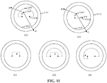
- FIG. 11 shows a schematic cross-sectional diagram of a model according to an embodiment.
- a first spherical model 1101, a second spherical model 1102, a third model 1103, and a virtual entry 1104 are included.
- an observation point 1105 is far away from the virtual entry 1104.
- the terminal when the third model exists on a line of sight of a view field area of the observation point, because the third model is prior to the second spherical model in the rendering order, and a model depth of the third model is less than a model depth of the second spherical model, the terminal only renders the first spherical model and the third model to obtain a picture for display.
- the terminal may further set the third model to be fully transparent.
- the picture for display is actually a video frame collected from the real scene and drawn on an inner side of a spherical surface of the first spherical model. In other words, it is ensured that the real scene is displayed outside the virtual entry.
- a line of sight OA starting from the observation point 1105 and not passing through the virtual entry 1104 successively passes through the third model, the second spherical model, and the first spherical model, as shown in FIG. 12(a) .
- a color obtained on a screen through rendering is: C3 ⁇ T3+ (1-C3) ⁇ T1 ⁇ C1.
- C3 may be set to 0, representing being fully transparent
- C1 may be set to 1, representing being opaque. Therefore, the color displayed on the screen is the color of the first spherical model, that is, it is displayed the image frame collected from the real scene and drawn on the inner side of the spherical surface of the first spherical model.
- the terminal When the third model does exist on the line of sight of the view field area of the observation point, the terminal only renders the first spherical model and the second spherical model to obtain a picture for display.
- the terminal may set the second spherical model to be opaque. Therefore, the picture for display is actually a video frame for drawing a panoramic video on the inner side the spherical surface of the second spherical model. In other words, it is ensured that virtual content is displayed in the virtual entry.
- a line of sight OB starting from the observation point 1105 and passing through the virtual entry 1104 successively passes through the second spherical model and the first spherical model, as shown in FIG. 12(b) .
- a rendering order is: the first spherical model ⁇ the second spherical model. It is assumed that a color of the second spherical model is C2 and transparency of the second spherical model is T2; and a color of the first spherical model is C1, and transparency of the first spherical model is T1.
- a color displayed on a screen obtained through rendering is: C2 ⁇ T2+(1-C2) ⁇ T1 ⁇ C1.
- C2 may be set to 1, representing being opaque
- C1 may be set to 1, representing being opaque. Therefore, the color displayed on the screen is the color of the second spherical model, that is, it is displayed the video frame of the panoramic video drawn on the inner side of the spherical surface of the second spherical model.
- the third model when the user enters the virtual entry, the third model is used for triggering to cancel rendering of the panoramic video on the second spherical model in a view field area which is outside the virtual entry and which is in the current view field area in a case that the current view field area covers the virtual entry and the third model is used for triggering to cancel rendering of the panoramic video on the second spherical model in a case that the current view field area does not cover the virtual entry.
- the user sees content of the panoramic video when the user does not see the virtual entry, and content of the real scene is displayed in the virtual entry and content of the panoramic video is displayed outside the virtual entry when the user sees the virtual entry.
- the image processing method further includes: rendering the first spherical model, the second spherical model, and a fully transparent fourth model in a current view field area according to a rendering order and an ascending order of model depths, to obtain a picture for display, in a case that the quantity of times for which the position of the current terminal passes through the space area is an odd number.
- the model depth of the second spherical model is greater than a model depth of the fourth model.
- the fourth model is used for triggering to cancel rendering of the second spherical model in a view field area which is outside the virtual entry and which is in the current view field area in a case that the current view field area covers the virtual entry or the fourth model is used for triggering to cancel rendering of the second spherical model in a case that the current view field area does not cover the virtual entry.
- the terminal may create a fourth model surrounding the observation point, and set the rendering order to: the first spherical model ⁇ the fourth model ⁇ the second spherical model.
- An interface of the fourth model is the virtual entry.
- a first spherical model 1101, a second spherical model 1102, a fourth model 1106, and a virtual entry 1104 are included.
- an observation point 1107 is far away from the virtual entry 1104.
- the terminal when the fourth model exists on a line of sight of a view field area of the observation point, because the fourth model is prior to the second spherical model in the rendering order, and a model depth of the fourth model is less than a model depth of the second spherical model, the terminal only renders the first spherical model and the fourth model to obtain a picture for display.
- the terminal may further set the fourth model to be fully transparent.
- the picture for display is actually a video frame collected from the real scene and drawn on an inner side of a spherical surface of the first spherical model. In other words, it is ensured that the real scene is displayed in the virtual entry.
- a line of sight OC starting from the observation point 1107 and passing through the virtual entry 1104 successively passes through the fourth model, the second spherical model, and the first spherical model, as shown in FIG. 12(c) .
- a rendering order is: the first spherical model ⁇ the fourth model ⁇ the second spherical model
- a color of the fourth model is C4 and transparency of the fourth model is T4
- a color of the second spherical model is C2
- transparency of the second spherical model is T2
- a color of the first spherical model is C1, and transparency of the first spherical model is T1.
- a color displayed on a screen obtained through rendering is C4 ⁇ T4+ (1-C4) ⁇ T1 ⁇ C1.
- C4 may be set to 0, representing being fully transparent
- C1 may be set to 1, representing being opaque
- the color displayed on the screen is the color of the first spherical model, that is, it is displayed the image frame collected from the real scene and drawn on the inner side of the spherical surface of the first spherical model.
- the terminal When there is no third model exists on the line of sight of the view field area of the observation point, the terminal only renders the first spherical model and the second spherical model to obtain a picture for display.
- the terminal may set the second spherical model to be opaque.
- the picture for display is actually a video frame for drawing a panoramic video on the inner side of the spherical surface of the second spherical model. That is to say, it is ensured that virtual content is displayed outside the virtual entry.
- a line of sight OB starting from an observation point 1107 and passing through the virtual entry 1104 successively passes through the second spherical model and the first spherical model, as shown in FIG. 12(d) .
- a rendering order is: the first spherical model ⁇ the second spherical model
- the color of the second spherical model is C2 and transparency of the second spherical model is T2
- a color of the first spherical model is C1
- transparency of the first spherical model is T1
- a color displayed on a screen obtained through rendering is: C2 ⁇ T2+(1-C2) ⁇ T1 ⁇ C1.
- C2 may be set to 1, representing being opaque
- C1 may be set to 1, representing being opaque. Therefore, the color displayed on the screen is the color of the second spherical model, that is, it is displayed the video frame of the panoramic video drawn on the inner side of the spherical surface of the second spherical model.
- the fourth model when the user does not enter the virtual entry, the fourth model is used for triggering to cancel rendering of the panoramic video content on the second spherical model in a view field area which is outside the virtual entry and which is in the current view field area in a case that the current view field area covers the virtual entry and the fourth model is used for triggering to cancel rendering of the panoramic video content on the second spherical model in a case that the current view field area does not cover the virtual entry.
- FIG. 12(c) is a cross-sectional view of a model when a quantity of times for which the position of the current terminal passes through the space area is an odd number and the current terminal faces and is close to the virtual entry.
- FIG. 12(d) is a cross-sectional view of a model when the position of the current terminal never passes through the space area or a quantity of times for which the position of the current terminal passes through the space area is an even number, and the current terminal faces and is close to the virtual entry.
- FIG. 12(d) is a cross-sectional view of a model when the position of the current terminal never passes through the space area or a quantity of times for which the position of the current terminal passes through the space area is an even number, and the current terminal faces and is close to the virtual entry.
- 12(e) is a cross-sectional view of a model when the position of the current terminal never passes through the space area or the quantity of times for which the position of the current terminal passes through the space area is an even number and the current terminal moves around one side of the virtual entry.
- the third model is flipped on a plane on which the virtual entry is located. In this way, it is ensured that the virtual content is still displayed in the virtual entry and the image frame collected from the real world is still displayed outside the virtual entry. In other words, only after the terminal passes through the virtual entry, the content displayed in the virtual entry and the content displayed outside the virtual entry are exchanged.
- the terminal renders a three-dimensional spherical space in the camera.
- a texture image of a panoramic video is attached and played in the spherical space, the image frame collected from the real scene is played on a spherical surface with a spherical diameter greater than a spherical diameter of the spherical space or is played on a model plane in front of the observation point.
- the terminal then simulates an anywhere door when the trigger condition is met, to display the virtual world in the door and display an image of the real world outside the door.
- the user may move a position of the user from the outside of the door to the inside of the door to view the virtual world inside the door, or move from the inside of the door to the outside of the door to view the real world outside the door, so as to experience a passing-through effect between the virtual world and the real world.
- the door When a person enters an any door and is far away from the door, the door is used as a fourth model that is completely transparent.
- the real world is displayed in the door, and the virtual world is displayed outside the door, that is, the person is in the virtual world.
- the person enters an any door and is extremely close to the door in order to avoid causing rendering jitter when the person passes through the door, a small room just fitting the door is temporarily placed opposite to the door, the door itself is empty and the small room is completely transparent.
- the real world is displayed in the door, and the virtual world is displayed outside the door, that is, the person is in the virtual world.
- a third model surrounding the observation point is created by using the door as a local boundary.
- An area at which the door is located on the third model is empty, and the other area is fully transparent.
- the virtual world is displayed in the door, and the real world is displayed outside the door, that is, the person is in the real world.
- the door is used as a boundary and the boundary is extended on the third model.
- the virtual world is displayed in the door, and the real world is displayed outside the door, that is, the person is in the real world.
- a boundary of one side at which the observation point is located in the third model is extended.
- the third model is flipped on a plane on which the door is located. In this way, when the person looks out through the door, the virtual world is still displayed in the door, and the real world is still displayed outside the door, that is, the person is in the real world.
- the third model and the boundary of the third model may be a plane or a curved surface.
- FIG. 13 is a flowchart of an image processing method according to an exemplary embodiment.
- a user holds a terminal and collects an image frame from a real scene through a camera of the terminal.
- the terminal constructs a map according to the collected image frame, and detects whether the image frame includes a hand area. If the terminal does not detect that the image frame includes the hand area, the terminal continues to detect a subsequently collected image frame. If the terminal detects that the image frame includes the hand area, the terminal determines whether a gesture type corresponding to the hand area is a trigger type. If the gesture type is not the trigger type, the terminal continues to detect a subsequently collected image frame.
- the terminal recognizes a movement reference point of the hand area in the image frame and renders a particle animation at the movement reference point to highlight a trajectory formed by a movement of the hand.
- the terminal may continue to determine whether the trajectory meets a trigger condition. If the trajectory does not meet the trigger condition, the terminal continues to detect a subsequently collected image frame. If the trajectory meets the trigger condition, the terminal triggers to render a virtual entry.
- the terminal determines a position corresponding to the hand in the real scene, renders the virtual entry in the currently played image frame according to the position, displays a panoramic video in the virtual entry, and displays the real scene outside the virtual entry.
- the user may hold the terminal to move, and the terminal then determines whether the terminal passes through the virtual entry. If the terminal determines that the terminal passes through the virtual entry, a video picture of the panoramic video in a current view field area is directly displayed. If the terminal determines that the terminal does not pass through the virtual entry, the panoramic video is still displayed in the virtual entry, and the real scene is displayed outside the virtual entry.
- the terminal may further perform screen recording according to a user instruction, and share a video obtained through the screen recording.
- the terminal may further display guidance information.
- the guidance information may be a text, a voice, or a picture.
- the guidance information includes information for guiding the user to control the movement of the target object to meet the trigger condition, for example, "Use a finger to draw a circle in front of a rear camera, so as to open an any door", as shown in FIG. 3(b) .
- the guidance information may further include information that guides the user to move toward the virtual entry, for example, an arrow pointing to the virtual entry, as shown in FIG. 4(b) .
- steps in the flowcharts of the foregoing embodiments are displayed in order according to arrows, the steps are not necessarily performed in the order indicated by the arrows. Unless clearly stated herein, the steps are not performed strictly in the order, and the steps may be performed in other orders. Moreover, at least a part of the steps in the foregoing embodiments may include multiple sub-steps or multiple stages. The sub-steps or stages are not necessarily performed at the same time, but may be performed at different moments. The sub-steps or stages are not necessarily performed successively in order, but may be performed in turn or alternately with at least a part of other steps or sub-steps or stages of other steps.
- an image processing apparatus 1400 includes an obtaining module 1401, a playing module 1402, a determining module 1403 and a rendering module 1404.
- the obtaining module 1401 is configured to obtain image frames from image frames collected from a real scene.
- the playing module 1402 is configured to play the obtained image frames one by one according to a collection time sequence in which the obtained image frames are collected.
- the determining module 1403 is configured to determine a position corresponding to a target object in the real scene in a case that a trajectory formed by a movement of the target object in the obtained image frames meets a trigger condition.
- the rendering module 1404 is configured to render a virtual entry in a currently played image frame according to the position, and display virtual content in the virtual entry.
- the target object is a hand.
- the determining module 1403 is further configured to: segment each of the obtained image frames to obtain a hand image; recognize a gesture type corresponding to the hand image; determine a movement reference point in each of the obtained image frames in a case that the gesture type is a trigger type; and determine, according to the movement reference points, a trajectory formed by a movement of the hand.
- the determining module 1403 is further configured to: encode the obtained image frame into a semantic segmentation feature matrix through a hand recognition model; decode the semantic segmentation feature matrix to obtain a semantically segmented image, where a pixel point in the semantically segmented image has a pixel value that represents a classification category to which the pixel point belongs, and pixel points in the semantically segmented image are corresponding to pixel points in the obtained image frame; and segment the obtained image frame to obtain a hand image according to pixel points belonging to a hand category.
- the rendering module 1404 is further configured to: replace, in played image frames, pixel values of pixel points through which the trajectory passes with reference pixel values in a case that the trigger condition is not met; and play a reference animation in the currently played image frame according to the position in a case that the trigger condition is met.
- the determining module 1403 is further configured to determine a world coordinate position of the target object in a world coordinate space.
- the rendering module 1404 is further configured to render the virtual entry in the currently played image frame according to a camera coordinate position corresponding to the world coordinate position in a camera coordinate space.
- the rendering module 1404 is further configured to: obtain a position and a posture of a current terminal; determine a transformation matrix between a current camera coordinate space and the world coordinate space according to the position and the posture of the current terminal; transform the world coordinate position into the camera coordinate position in the camera coordinate space according to the transformation matrix; and render the virtual entry in the currently played image frame according to the camera coordinate position.
- the rendering module 1404 is further configured to: select, from a map, a map node matching the obtained image frame; query for a stored position that is in the real scene and that corresponds to the map node; obtain sensor data acquired by an inertial sensor; and determine the posture of the current terminal in the real scene according to the sensor data.
- the image processing apparatus 1400 further includes a map construction module 1405 configured to: select an image frame from image frames collected according to a time sequence; take the selected image frame as a node image in a case that an image feature of the selected image frame conforms to an image feature of the node image; determine a map node corresponding to the node image in the map; and store, corresponding to the determined map node, the image feature of the node image and a position at which the node image is collected in the real scene.
- a map construction module 1405 configured to: select an image frame from image frames collected according to a time sequence; take the selected image frame as a node image in a case that an image feature of the selected image frame conforms to an image feature of the node image; determine a map node corresponding to the node image in the map; and store, corresponding to the determined map node, the image feature of the node image and a position at which the node image is collected in the real scene.
- the rendering module 1404 is further configured to: project vertexes of a model of the virtual entry into pixel points corresponding to the vertexes of the model in an image coordinate space; combine the pixel points corresponding to the vertexes of the model into a pattern primitive according to a connection relationship between the vertexes of the model; and render rasterized pattern primitive according to pixel values of the pixel points in the pattern primitive at an image coordinate position corresponding to the camera coordinate position in the image coordinate space, to obtain the virtual entry.
- virtual content is a panoramic video.
- the rendering module 1404 is further configured to: determine a space area corresponding to the virtual entry in the real scene; and directly display a video picture of the panoramic video within a current view field area after a position of a current terminal passes through the space area.
- the rendering module 1404 is further configured to: determine, after the video picture of the panoramic video within the current view field area is directly displayed, a view field area which is of the current view field area and which is within the virtual entry in a case that the position of the current terminal does not pass through the space area again and the current view field area is moved to cover the virtual entry; and display, in the virtual entry, a picture of the obtained image frame within the determined view field area.
- the rendering module 1404 is further configured to: determine a view field area which is of the current view field area and which is within the virtual entry in a case that the position of the current terminal is moved around the space area; and display, in the virtual entry, a video picture of the panoramic video within the determined view field area.
- the virtual content is a panoramic video.
- the rendering module 1404 is further configured to: draw the obtained image frame on an inner side of a spherical surface of a first spherical model, and draw a panoramic video picture of the panoramic video on an inner side of a spherical surface of a second spherical model; determine a space area corresponding to the virtual entry in the real scene; and render the first spherical model, the second spherical model, and a fully transparent third model in a current view field area according to a rendering order and an ascending order of model depths, to obtain a picture for display, in a case that a position of a current terminal never passes through the space area, or a quantity of times for which the position of the current terminal passes through the space area is an even number.
- a spherical radius of the first spherical model is greater than a spherical radius of the second spherical model.
- a model depth of the first spherical model is greater than a model depth of the second spherical model.
- the model depth of the second spherical model is greater than a model depth of the third model.
- the third model is used for triggering to cancel rendering of the second spherical model in a view field area which is outside the virtual entry and which is in the current view field area in a case that the current view field area covers the virtual entry or the third model is used for triggering to cancel rendering of the second spherical model in a case that the current view field area does not cover the virtual entry.
- the rendering module 1404 is further configured to: render the first spherical model, the second spherical model, and a fully transparent fourth model in a current view field area according to a rendering order and an ascending order of model depths, to obtain a picture for display, in a case that the quantity of times for which the position of the current terminal passes through the space area is an odd number.
- the model depth of the second spherical model is greater than a model depth of the fourth model.
- the fourth model is used for triggering to cancel rendering of the second spherical model in a view field area which is outside the virtual entry and which is in the current view field area in a case that the current view field area covers the virtual entry or the fourth model is used for triggering to cancel rendering of the second spherical model in a case that the current view field area does not cover the virtual entry.
- FIG. 16 shows an internal structure diagram of a computer device according to an embodiment.
- the computer device may be the terminal 110 in FIG. 1 .
- the computer device includes a processor, a memory, a network interface, an input apparatus, and a display screen that are connected through a system bus.
- the memory includes a non-volatile storage medium and an internal memory.
- the non-volatile storage medium of the computer device stores an operating system and may further store a computer program, the computer program, when executed by the processor, causing the processor to implement the image processing method.
- the internal memory may also store a computer program, the computer program, when executed by the processor, causing the processor to perform the image processing method.
- the display screen of the computer device may be a liquid crystal display screen or an electronic ink display screen.
- the input apparatus may be a touch layer covering the display screen, or may be a key, a trackball, or a touch pad disposed on a housing of the computer device, or an external keyboard, touch pad, or mouse. It may be understood by a person skilled in the art that the structure shown in FIG. 16 is only a block diagram of a part of the structure related to the solution of this disclosure, and does not constitute a limitation on the computer device to which the solution of this disclosure is applied.
- the computer device may specifically include more or fewer components than those shown in the figure, or be combined with some components, or have a different component arrangement.
- the image processing apparatus provided in this disclosure may be implemented in a form of a computer program.
- the computer program may be run on the computer device shown in FIG. 16 .
- the non-volatile storage medium of the computer device may store program modules included in the image processing apparatus, such as the obtaining module 1401, the playing module 1402, the determining module 1403, and the rendering module 1404 shown in FIG. 14 .
- the computer program formed by the program modules causes the processor to perform the operations in the image processing method of the embodiments of this disclosure described in the specification.
- the computer device shown in FIG. 16 may obtain image frames from image frames collected from a real scene through the obtaining module 1401 in the image processing apparatus 1400 shown in FIG. 14 , play the obtained image frames one by one according to a collection time sequence in which the obtained image frames are collected through the playing module 1402, determine a position corresponding to a target object in the real scene through the determining module 1403 in a case that a trajectory formed by a movement of the target object in the multiple obtained image frames meets a trigger condition, and render a virtual entry in a currently played image frame according to the position through the rendering module 1404, and display virtual content in the virtual entry.
- a computer-readable storage medium storing a computer program, the computer program, when executed by a processor, causing the processor to perform any one of the foregoing image processing methods.
- a computer device including a memory and a processor, the memory storing a computer program, the computer program, when executed by the processor, causing the processor to perform any one of the foregoing image processing methods.
- the non-volatile memory may include a read-only memory (ROM), a programmable ROM (PROM), an electrically programmable ROM (EPROM), an electrically erasable programmable ROM (EEPROM), or a flash memory.
- ROM read-only memory
- PROM programmable ROM
- EPROM electrically programmable ROM
- EEPROM electrically erasable programmable ROM
- the volatile memory may include a random access memory (RAM) or an external cache.
- the RAM is available in multiple forms, such as a static RAM (SRAM), a dynamic RAM (DRAM), a synchronous DRAM (SDRAM), a double data rate SDRAM (DDRSDRAM), an enhanced SDRAM (ESDRAM), a synchronous link (Synchlink) DRAM (SLDRAM), a Rambus direct RAM (RDRAM), a direct Rambus dynamic RAM (DRDRAM), and a Rambus dynamic RAM (RDRAM).
- SRAM static RAM
- DRAM dynamic RAM
- SDRAM synchronous DRAM
- DDRSDRAM double data rate SDRAM
- ESDRAM enhanced SDRAM
- SLDRAM synchronous link
- RDRAM Rambus direct RAM
- DRAM direct Rambus dynamic RAM
- RDRAM Rambus dynamic RAM
Landscapes
- Engineering & Computer Science (AREA)
- Theoretical Computer Science (AREA)
- General Engineering & Computer Science (AREA)
- Physics & Mathematics (AREA)
- General Physics & Mathematics (AREA)
- Human Computer Interaction (AREA)
- Computer Graphics (AREA)
- Software Systems (AREA)
- Computer Hardware Design (AREA)
- Computing Systems (AREA)
- Geometry (AREA)
- Multimedia (AREA)
- Radar, Positioning & Navigation (AREA)
- Remote Sensing (AREA)
- Social Psychology (AREA)
- Psychiatry (AREA)
- General Health & Medical Sciences (AREA)
- Computer Vision & Pattern Recognition (AREA)
- Health & Medical Sciences (AREA)
- Processing Or Creating Images (AREA)
- User Interface Of Digital Computer (AREA)
- Position Input By Displaying (AREA)
Abstract
Description
- This application claims priority to Chinese Patent Application No.
201810494117.8 - This disclosure relates to the field of computer technologies, and in particular, to an image processing method and an image processing apparatus, a storage medium, and a computer device.
- With the development of computer technologies, image processing technologies are increasingly improved. A user may process an image through professional image processing software to better present the processed image. The user may further add a material provided by the image processing software to the image through the image processing software, so that the processed image can convey more information.
- However, in a current image processing manner, the user needs to open a material library of the image processing software, browse the material library, select a suitable material from the material library, adjust a position of the material in the image, to determine the modification, and complete image processing. Therefore, the current image processing manner needs a lot of manual operations, which is time-consuming, resulting in low efficiency of the image processing process.
- Based on this, embodiments of this disclosure provide an image processing method, an image processing apparatus, a storage medium, and a computer device, to resolve the problem of low efficiency in a conventional image processing process.
- An image processing method includes: obtaining image frames from image frames collected from a real scene; playing the obtained image frames one by one according to a collection time sequence in which the obtained image frames are collected; determining a position corresponding to a target object in the real scene in a case that a trajectory formed by a movement of the target object in the obtained image frames meets a trigger condition; rendering a virtual entry in a currently played image frame according to the position; and displaying virtual content in the virtual entry.
- An image processing apparatus includes: an obtaining module, configured to obtain image frames from image frames collected from a real scene; a playing module, configured to play the obtained image frames one by one according to a collection time sequence in which the obtained image frames are collected; a determining module, configured to determine a position corresponding to a target object in the real scene in a case that a trajectory formed by a movement of the target object in the obtained image frames meets a trigger condition; and a rendering module, configured to render a virtual entry in a currently played image frame according to the position, and display virtual content in the virtual entry.
- A computer-readable storage medium storing a computer program. The computer program, when executed by a processor, causes the processor to perform following operations: obtaining image frames from image frames collected from a real scene; playing the obtained image frames one by one according to a collection time sequence in which the obtained image frames are collected; determining a position corresponding to a target object in the real scene in a case that a trajectory formed by a movement of the target object in the obtained image frames meets a trigger condition; rendering a virtual entry in a currently played image frame according to the position; and displaying virtual content in the virtual entry.
- A computer device includes a memory and a processor. The memory stores a computer program. The computer program, when executed by the processor, causes the processor to perform following operations: obtaining image frames from image frames collected from a real scene; playing the obtained image frames one by one according to a collection time sequence in which the obtained image frames are collected; determining a position corresponding to a target object in the real scene in a case that a trajectory formed by a movement of the target object in the obtained image frames meets a trigger condition; rendering a virtual entry in a currently played image frame according to the position; and displaying virtual content in the virtual entry.
- In the foregoing image processing method, image processing apparatus, storage medium, and computer device, on the one hand, the image frames reflecting the real scene are played, so that the played image frames can reflect the real scene; on the other hand, the position corresponding to the target object in the real scene is automatically determined in a case that the trajectory formed by the movement of the target object in the image frames obtained from image frames which are collected from the real scene meets the trigger condition, to render the virtual entry in the currently played image frame according to the determined position and display the virtual content in the virtual entry. In this way, the virtual content of the virtual world can be displayed in the virtual entry, and real content of the real world can be displayed outside the virtual entry, thereby avoiding complicated steps of manual operations and greatly improving the image processing efficiency.
-
-
FIG. 1 is an application environment diagram of an image processing method according to an embodiment. -
FIG. 2 is a schematic flowchart of an image processing method according to an embodiment. -
FIG. 3 is a schematic diagram of an interface on which an image frame is played according to an embodiment. -
FIG. 4 is a schematic diagram of an interface on which a virtual entry is rendered in a currently played image frame according to an embodiment. -
FIG. 5 is a schematic diagram of a hand area obtained by segmenting an obtained image frame according to an embodiment. -
FIG. 6 shows schematic diagrams of trajectory changes in image frames according to an embodiment. -
FIG. 7 is a schematic diagram of a relationship between coordinate spaces according to an embodiment. -
FIG. 8 is a principle diagram of rendering after a position of a current terminal passes through a space area according to an embodiment. -
FIG. 9 is a schematic diagram of an interface displayed on a terminal interface when the position of the current terminal does not pass through the space area again and a current view field area is moved to cover a virtual entry according to an embodiment. -
FIG. 10 is a principle diagram of rendering when the position of the current terminal is moved around a space area according to an embodiment. -
FIG. 11 is a schematic cross-sectional diagram of a model according to an embodiment. -
FIG. 12 is a schematic principle diagram of rendering according to an embodiment. -
FIG. 13 is a flowchart of an image processing method according to an embodiment. -
FIG. 14 is a module structure diagram of an image processing apparatus according to an embodiment. -
FIG. 15 is a module structure diagram of an image processing apparatus according to another embodiment. -
FIG. 16 is an internal structure diagram of a computer device according to an embodiment. - To make the objectives, technical solutions, and advantages of this disclosure clearer, the following further describes this disclosure in detail with reference to the accompanying drawings and the embodiments. It is to be understood that the specific embodiments described herein are only used for describing this disclosure, instead of limiting this disclosure.
-
FIG. 1 is an application environment diagram of an image processing method according to an embodiment. Referring toFIG. 1 , the image processing method is applied to an image processing system. The image processing system includes aterminal 110 and aserver 120. Theterminal 110 and theserver 120 are connected via a network. Theterminal 110 is configured to perform the image processing method. Exemplarily, theterminal 110 may be a desktop terminal or a mobile terminal. The mobile terminal may be at least one of a mobile phone, a tablet computer, a notebook computer, and the like. Theserver 120 may be an independent server or a server cluster formed by multiple independent servers. - The
terminal 110 may obtain image frames from image frames collected from a real scene, and play the obtained image frames one by one according to a collection time sequence in which the obtained image frames are collected. The image frames may be collected by theterminal 110 from the real world through a built-in image collection apparatus or an externally connected image collection apparatus. The built-in image collection apparatus may be a front camera or a rear camera of theterminal 110. The image frames may be alternatively sent to theterminal 110 after being collected from the real scene by another device. Theterminal 110 may determine a position corresponding to a target object in the real scene in a case that it is locally determined that a trajectory formed by a movement of the target object in the multiple obtained image frames meets a trigger condition, and then theterminal 110 may render a virtual entry in a currently played image frame according to the position, and display virtual content in the virtual entry. Theterminal 110 may alternatively send the collected image frames to theserver 120, theserver 120 notifies theterminal 110 that a trigger condition is met in a case that the server determines that a trajectory formed by a movement of the target object in the multiple obtained image frames meets the trigger condition, and then theterminal 110 determines a position corresponding to the target object in the real scene, renders a virtual entry in a currently played image frame according to the position, and displays virtual content in the virtual entry. -
FIG. 2 is a schematic flowchart of an image processing method according to an embodiment. In this embodiment, an example in which the image processing method is applied to a computer device is mainly used for description. The computer device may be theterminal 110 inFIG. 1 . Referring toFIG. 2 , the image processing method includes the following steps S202 to S210. - S202: Obtain image frames from image frames collected from a real scene.
- The real scene is a scene existing in the natural world. The image frame is a unit in an image frame sequence that can form a dynamic picture and is used for recording a picture in the real scene at a certain moment.
- In an embodiment, the terminal may collect the image frames from the real scene at a fixed or dynamic frame rate and obtain image frames from the collected image frames. The fixed or dynamic frame rate enables the image frames to form a continuous dynamic picture when the image frames are played at the fixed or dynamic frame rate.
- In an embodiment, the terminal may collect image frames from the real scene through a built-in or externally connected image collection apparatus such as a camera in a current view field area of the camera, and obtain image frames from the collected image frames. The view field area of the camera may change due to changes in a posture and a position of the terminal.
- In an exemplary embodiment, the terminal may select an augmented reality (AR) photographing mode provided by an application running on a local machine to collect image frames from the real scene, and obtain image frames from the collected image frames. The application may be a social application. The social application is an application that can perform network social interaction based on a social network. The social application includes an instant messaging application, a social network service (SNS) application, a live streaming application, or a photographing application, such as QQ or WeChat.
- In an embodiment, the terminal may receive image frames collected from the real scene and sent by another terminal, and obtain image frames from the received image frames. For example, when establishing a video session through a social application running on the terminal, the terminal receives image frames collected from the real scene and sent by a terminal corresponding to another session party.
- In an embodiment, the frame rate at which the image frames are obtained may be the same as a frame rate at which the image frames are collected or may be less than the frame rate at which the image frames are collected.
- S204: Play the obtained image frames one by one according to a collection time sequence in which the obtained image frames are collected.
- The collection time sequence refers to a time sequence in which the obtained image frames are collected, and may be represented through a relationship of timestamps of the image frames recorded during collection. Playing the frames one by one refers to playing the image frames frame by frame.
- Exemplarily, the terminal may play the obtained image frames one by one in ascending order of the timestamps according to a frame rate at which the image frames are obtained. The terminal may play the obtained image frames directly. Alternatively, the terminal may store the obtained image frames in a buffer area according to the collection time sequence, and extract, according to the collection time sequence, the obtained image frames from the buffer area for play.
- In an embodiment, the terminal may play, one by one in ascending order of the timestamps according to a frame rate at which the another terminal collects the image frames, the received image frames sent by the another terminal and collected from the real scene. The terminal may play the received image frames directly. Alternatively, the terminal may store the received image frames in a buffer area according to a collection time sequence, and extract, according to the collection time sequence, the image frames from the buffer area for play.
-
FIG. 3 shows a schematic diagram of an interface on which an image frame is played according to an embodiment. Referring toFIG. 3, FIG. 3(a) is a simplified schematic diagram of a terminal interface on which an image frame is played, andFIG. 3(b) is a screenshot of the terminal interface on which the image frame is played. It can be seen that a picture in a real scene is displayed on a display screen of the terminal. - S206: Determine a position corresponding to a target object in the real scene in a case that a trajectory formed by a movement of the target object in the multiple obtained image frames meets a trigger condition.
- The target object is an entity as a target in the real scene. The target object may be a hand, a face, an elongated object or the like. The trajectory formed by the movement of the target object may be a trajectory formed by a movement of a reference point of the target object in the obtained image frames when the target object is moving. For example, a trajectory formed by a movement of an imaging point of an index finger fingertip of a hand in the obtained image frames when a user controls the hand to move. For another example, a trajectory formed by a movement of an imaging point of a top of an elongated object in the obtained image frames when the user holds the elongated object (such as a pen or a magic wand) to move.
- The trigger condition is a constraint condition under which a specific event is triggered. In this embodiment, the specific event is an event in which a virtual entry is rendered in a played image frame. The trigger condition may be that the trajectory formed by the movement of the target object in the multiple obtained image frames is a regular closed shape, such as a triangle, a quadrangle, or a circle.
- It may be understood that the user may select the target object, and control the target object to move in the real scene, so that the trajectory formed by the movement of the target object in the obtained image frames of the target object meets a specific constraint condition (such as the trigger condition), to trigger the specific event (rendering the virtual entry). A position corresponding to the target object in the real scene is a mapping of a position, at which the user intends to render the virtual entry by using the terminal in the played image frame, in the real scene. In this way, visual perception of the user is to trigger a virtual entry to appear in the real world, just like a real entry in the real world.
- Exemplarily, when the trajectory formed by the movement of the target object in the multiple obtained image frames meets the trigger condition, the terminal determines a coordinate position of the target object in the image frame, and calculates a position of the target object in the real scene according to a projection matrix adapted to an image collection apparatus of the terminal. The coordinate position of the target object in the image frame may be specifically a coordinate position of a reference point of the target object in the image frame, for example, a coordinate position of an imaging point of an index finger fingertip of a hand. The coordinate position of the target object in the image frame may be alternatively a coordinate position of a centre of a trajectory formed by the movement of the target object, for example, a coordinate position of a centre of a trajectory of a circle when an index finger fingertip of a hand draws the circle.
- In an exemplary application scenario, the user holds a terminal and starts a built-in camera on the terminal by using an application program for invoking the camera on the terminal, so that the terminal may collect image frames from a real scene in a current view field area of the camera. The user controls the camera of the terminal to collect a movement of a target object, so as to obtain image frames which include the target object and which are collected in real time. It may be understood that if the user starts a front camera, the collected image frame includes the target object and a background in the current view field area of the front camera. If the user starts a rear camera, the collected image frame includes the target object and a background in the current view field area of the rear camera.
- S208: Render a virtual entry in a currently played image frame according to the position.
- The virtual entry is a concept relative to a real entry. The real entry is an entity used for dividing a real space in the real scene. The real entry, such as a room door, may divide the real space into an indoor area and an outdoor area. Alternatively, the real entry, such as an entry to a scenic spot, may divide the real space into a scenic spot and a non-scenic spot. The virtual entry is a virtual model used for dividing an area in a virtual scene. The virtual entry is, for example, a virtual model door or the like.
- It may be understood that a position in the real scene is an absolute position in the real space. The position does not change due to changes in a current view field area of a built-in or externally connected image collection apparatus of the terminal. It can be seen that, when the current view field area of the image collection apparatus changes, a rendering position and a rendering size of the virtual entry in the image frame are changed. Therefore, when the current view field area of the image collection apparatus changes, the rendering position and the rendering size of the virtual entry in the image frame present a foreshortening effect based on an object imaging principle in the real world.
- Exemplarily, the terminal may calculate, after determining the position of the target object in the real scene, a rendering position of the virtual entry in the image frame collected in the current view field area according to the real scene and a projection matrix adapted to the image collection apparatus of the terminal in the current view field area, and render the virtual entry at the position.
-
FIG. 4 shows a schematic diagram of an interface on which a virtual entry is rendered in a currently played image frame according to an embodiment. Referring toFIG. 4, FIG. 4(a) is a simplified schematic diagram of a terminal interface on which a virtual entry is rendered in a currently played image frame, andFIG. 4(b) is a screenshot of the terminal interface on which the virtual entry is rendered in the currently played image frame.FIG. 4(a) includes a renderedvirtual entry 410a, andFIG. 4(b) includes a renderedvirtual entry 410b. - S210: Display virtual content in the virtual entry.
- The virtual content herein is content that does not exist in a real scene from which the obtained image frame is collected. If the obtained image frame is collected from a real scene A, the virtual content is content that does not exist in the real scene A. It may be understood that the virtual content herein is virtual content relative to a current real scene, but not absolute virtual content. In other words, the virtual content herein may be completely virtual content simulated through computer technologies, or content in a non-current real scene. The current real scene is a real scene from which the image frame obtained by the terminal is collected.
- In an embodiment, the virtual content may be dynamic content or static content. The virtual content may be unified content, content corresponding to a trajectory formed by a movement of a target object in the image frames, or content selected by the user independently. Exemplarily, the terminal may set a correspondence between the trajectory and the virtual content, so that the terminal may query, after recognizing the trajectory, the virtual content corresponding to the trajectory for display. For example, when the trajectory is a triangle, the displayed virtual content is a football game video; when the trajectory is a quadrangle, the displayed virtual content is a video of a captured shopping mall; and when the trajectory is a circle, the displayed virtual content is a video of a captured scenic spot. The terminal may further display a selection dialog box, display available virtual content in the selection dialog box, and then display virtual content selected by a user selection instruction in the virtual entry.
- In an embodiment, the virtual content may be a virtual video or a video generated by collecting image frames from a real scene. For example, if the user holds the terminal at an office to collect a real scene at the office to obtain image frames for play, content displayed outside the virtual entry is the real scene of the office, content displayed in the virtual entry may be a game video, or a real scene collected by another image collection apparatus in a place other than the current office, such as Wangfujing Street.
- Still referring to
FIG. 4 , it can be seen that the virtual content is displayed in the virtual entrys 410a and 410b, and a picture in the real scene is displayed outside the virtual entrys 410a and 410b. In this way, visual perception of the user is that a virtual world is displayed in the virtual entry, and a real world is displayed outside the virtual entry. The user may view the virtual world in the virtual entry by moving to pass through the virtual entry, or view the real world outside the virtual entry by moving to go out of the virtual entry, so as to experience a passing-through effect between the virtual world and the real world. - In the foregoing image processing method, on the one hand, the image frames reflecting the real scene are played, so that the played image frames can reflect the real scene; on the other hand, the position corresponding to the target object in the real scene is automatically determined in a case that the trajectory formed by the movement of the target object in the image frames obtained from image frames which are collected from the real scene meets the trigger condition, to render the virtual entry in the currently played image frame according to the determined position and display the virtual content in the virtual entry. In this way, the virtual content of the virtual world can be displayed in the virtual entry, and real content of the real world can be displayed outside the virtual entry, thereby avoiding complicated steps of manual operations and greatly improving the image processing efficiency.
- In an embodiment, the target object is a hand. The image processing method further includes: segmenting each of the obtained image frames to obtain a hand image; recognizing a gesture type corresponding to the hand image; determining a movement reference point in each of the obtained image frames in a case that the gesture type is a trigger type; and determining, according to the movement reference points, a trajectory formed by a movement of the hand.
- The hand is a body part of a person or an animal. The hand image is an image including the hand and having a hand area accounting for a large proportion of the image area. The gesture is an action form made by the user through the hand. The gesture type is a type of the gesture in the obtained image frame. The trigger type is a type of the gesture that triggers a specific event.
- The movement reference point is a reference standard used for discriminating a movement process of the target object. It may be understood that changes in the position of the movement reference point in different image frames indicate that the target object moves. For example, an imaging point of an index finger fingertip is used as the movement reference point, and when a position of the imaging point of the index finger fingertip in the multiple image frames changes, it is determined that the hand moves.
- It may be understood that compared with directly recognizing the gesture type of a hand area in an obtained original image frame, segmenting the hand image from the obtained image frame and then recognizing the gesture type of the segmented hand image may avoid an inaccurate recognition caused when the hand image accounts for a small proportion of the entire image frame, so that the interference on the recognition of the gesture type of the hand area caused by the background area relative to the hand area in the original image frame can be reduced, and the recognition accuracy can be improved.
- In an embodiment, the segmenting each of the obtained image frames to obtain a hand image includes: encoding the obtained image frame into a semantic segmentation feature matrix through a hand recognition model; decoding the semantic segmentation feature matrix to obtain a semantically segmented image, where a pixel point in the semantically segmented image has a pixel value that represents a classification category to which the pixel point belongs, and pixel points in the semantically segmented image are corresponding to pixel points in the obtained image frame; and segmenting the obtained image frame to obtain a hand image according to pixel points belonging to a hand category.
- The hand recognition model is a machine learning model trained with a hand recognition capability. A full English name of machine learning is called ML for short. The machine learning model may have a specific capability through sample learning. The machine learning model may include a neural network model, a support vector machine, a logistic regression model, or the like. The neural network model is, for example, a convolutional neural network. In this embodiment, the hand recognition model may be a fully convolutional network model.
- The semantic segmentation feature matrix is a low-dimensional expression of a semantic feature of image content in the image frame and covers semantic feature information of the entire image frame. The semantically segmented image is an image segmented into several non-overlapping areas with certain meanings. A pixel value of a pixel point in the semantically segmented image is used for reflecting a classification category to which the corresponding pixel point belongs. The classification of the pixel points may be two-classification or multi-classification. The two-classification of the pixel points is, for example, a pixel point corresponding to a road in a map image and other pixel points. The multi-classification of the pixel points is, for example, a pixel point corresponding to sky in a scenery map, a pixel point corresponding to a ground, and a pixel point corresponding to a person, etc. An image size of the semantically segmented image is the same as an image size of the original image frame. In this way, it may be understood that a model input image is classified pixel point by pixel point. A category to which each pixel point in the model input image belongs may be obtained according to a pixel value of the pixel point in the semantically segmented image.
- Exemplarily, the terminal may obtain a hand recognition model through training by using image samples of each gesture type. In this way, the terminal uses the hand image as an input of the hand recognition model after segmenting the obtained image frame to obtain the hand image, and encodes the hand image into a semantic segmentation feature matrix through an encoding structure of the obtained hand recognition model. Then, the terminal continues to decode the semantic segmentation feature matrix through a decoding structure of the hand recognition model to obtain the semantically segmented image.
- When there is a unique gesture type for a trigger type that is set by the terminal, the hand recognition model is a two-classification model. Image samples used for training the two-classification model include a positive sample belonging to a target gesture type and a negative sample not belonging to the target gesture type. When there are multiple gesture types for the trigger type that are set by the terminal, the hand recognition model is a multi-classification model. Image samples used for training the multi-classification model include samples belonging to all target gesture types.
-
FIG. 5 shows a schematic diagram of a hand area obtained by segmenting an obtained image frame according to an embodiment. Referring toFIG. 5, FIG. 5(a) is an obtained original image frame including the hand area;FIG. 5(b) is a semantically segmented image obtained after semantic segmentation; andFIG. 5(c) is a regular hand image of the segmented hand area. - In this embodiment, after the image frame is obtained, the image frame is automatically inputted into the trained machine learning model, the image frame is encoded into a semantic segmentation feature matrix, and then the semantic segmentation feature matrix is decoded to obtain the semantically segmented image. A pixel point in the semantically segmented image has a pixel value that represents a classification category to which the pixel point belongs, and pixel points in the semantically segmented image correspond to pixel points in the original image frame. In this way, a hand area is automatically determined according to pixel points belonging to a hand category to segment a hand image, thereby improving the image segmentation accuracy.
- Further, the terminal may compare the segmented hand image with a hand image template of a trigger type, determine, when the segmented hand image matches the hand image template of the trigger type, that the gesture type corresponding to the hand image is the trigger type, and then determine movement reference points in the image frames; and determine, according to the movement reference points, a trajectory formed by a movement of the hand.
- The terminal may alternatively input the segmented hand image into a trained gesture recognition model to obtain a gesture recognition result outputted by the gesture recognition model, and then determine movement reference points in the image frames when the gesture recognition result indicates that a gesture type corresponding to the hand image is a trigger type; and determine, according to the movement reference points, a trajectory formed by a movement of the hand.
- In an exemplary scenario, a user makes a gesture toward a camera of the terminal, and determines a movement reference point of the gesture in each of collected continuous image frames when determining that an operation type corresponding to the gesture is a drawing type. Due to a high frequency at which the images are collected, continuous movement reference points may be connected by an extremely short line to form a trajectory.
- In an embodiment, the terminal may select an image frame from the obtained image frames according to a collection time sequence at a frame rate less than a frame rate at which the image frames are obtained, to perform the hand image segmenting and the gesture recognition. The selecting an image frame from the obtained image frames may be asynchronously selecting the image frame through multi-threading to independently perform the hand image segmenting and the gesture recognition, so that the recognition efficiency can be improved.
- In the foregoing embodiment, a specific gesture is made by using the hand to draw a specific trajectory across the air, so that a display effect of a virtual entry may be automatically triggered. The user does not need to perform an operation in the entire drawing process through an input apparatus, and the user may perform drawing by using a shown gesture in a relatively large space range, thereby improving the convenience for triggering the virtual entry.
- In an embodiment, the image processing method further includes: replacing, in played image frames, pixel values of pixel points through which the trajectory passes with reference pixel values in a case that the trigger condition is not met; and playing a reference animation in the currently played image frame according to the position in a case that the trigger condition is met.
- Exemplarily, when the trigger condition is not met, in order to visually highlight the trajectory formed by the movement of the target object and help the use intuitively perceive whether the trigger condition is met, the trajectory may be displayed by using pixel values different from those of the pixel points in the image. The trajectory is essentially a trajectory formed by pixel coordinates corresponding to movement reference points in multiple continuous image frames. Therefore, the terminal may determine the pixel points through which the trajectory passes in the image frame according to the pixel coordinates, and update the pixel values of the pixel points as the reference pixel values. The reference pixel value is, for example, a pixel value corresponding to relatively bright green or red.
- In an embodiment, the terminal may alternatively update the pixel values of the pixel points within a certain range centered on the pixel points through which the trajectory passes, as the reference pixel values. The terminal may alternatively render a particle animation at the pixel points through which the trajectory passes, and cover or replace the pixel values of the pixel points through which the trajectory passes to achieve an effect of a magic gesture movement.
- In an embodiment, the terminal may update the pixel values or render the particle animation in real time, and update the pixel values of the pixel points through which the trajectory passes once determining the pixel points through which the trajectory passes in the current image frame, or render the particle animation at the position of the pixel points, so that a movement trajectory can be displayed in real time.
-
FIG. 6 shows schematic diagrams of trajectory changes in image frames according to an embodiment. Referring toFIG. 6, FIG. 6 (a), FIG. 6 (b), and FIG. 6 (c) are simplified schematic diagrams of a terminal interface when a trajectory changes in the image frames, andFIG. 6 (d), FIG. 6(e) and FIG. 6(f) are screenshots of the terminal interface when the trajectory changes in the image frames. It can be clearly seen fromFIG. 6(a) or FIG. 6(d) that pixel values of pixel points through which the trajectory passes are updated to be different from original pixel values. It can be clearly seen fromFIG. 6(b) or FIG. 6(e) that the trajectory formed by a movement of a target object in the multiple obtained image frames is a circle, which meets a trigger condition. It can be clearly seen fromFIG. 6(c) or FIG. 6(f) that pixel points with values different from the original pixel values gradually approach the center of the trajectory to achieve an animation effect. - Further, when the trigger condition is met, the terminal may play a reference animation in a currently played image frame according to a position corresponding to the target object. In the reference animation, the pixel points updated as the reference pixel values are gradually restored to the original pixel values, or rendering of the particle animation is gradually cancelled, or the rendering is cancelled after the particle animation gradually approaches the center of the trajectory.
- In the foregoing embodiment, by updating the pixel values of the pixel points through which the trajectory passes in the image frame, a movement trajectory of the target object may be directly displayed in a current image frame to achieve a real-time drawing effect and improve user perception. In addition, after the trigger condition is met, the reference animation is played, which is more interesting.
- In an embodiment, the determining a position corresponding to a target object in the real scene includes: determining a world coordinate position of the target object in a world coordinate space. The rendering a virtual entry in a currently played image frame according to the position corresponding to the target object includes: rendering the virtual entry in the currently played image frame according to a camera coordinate position corresponding to the world coordinate position in a camera coordinate space. The world coordinate position is a coordinate position of the target object in the world coordinate space.
- The world coordinate space is a coordinate space of the real scene and is a fixed absolute coordinate space. The camera coordinate space is a coordinate space formed by using an intersection of an optical axis and an image plane as an origin, and is a relative coordinate space that changes with a position change of an image collection apparatus (a camera). The world coordinate position in the world coordinate space may be mapped as a camera coordinate position in the camera coordinate space through a rigid-body change.
- It may be understood that for a target object in the real scene, generally, when the target object does not move, a world coordinate position of the target object in the world coordinate space is fixed, but as the position and a posture of the image collection apparatus change, a camera coordinate position of the target object in the camera coordinate space is relatively unchanged.
- In this disclosure, the virtual entry is intended to be rendered, in the image frame, at a position at which the world coordinate position of a movement of the target object is mapped, so that the user perceives that the virtual entry exists at the world coordinate position of the movement of the target object. Therefore, the world coordinate position of the movement of the target object needs to be obtained, and then the camera coordinate position in the current camera coordinate space is determined in real time. For example, the user holds a terminal to draw a circle with the index finger fingertip of the hand in a view field area of a rear camera. In other words, a virtual door, that is, a virtual entry, appears at a position at which the circle is drawn by the finger in the real scene.
- Exemplarily, when determining that the trajectory formed by the movement of the target object in the multiple obtained image frames meets the trigger condition, the terminal may obtain an image coordinate position of the target object in the current image frame, obtain the camera coordinate position of the target object according to a projection change between the image coordinate space and the camera coordinate space, and then obtain a world coordinate position of the target object in the world coordinate space according to a rigid-body change between the camera coordinate space and the world coordinate space. The image coordinate space is a coordinate space using the center of the image as an origin, coordinate axes of the image coordinate space are parallel to sides of the image.
- It may be understood that because a projection change relationship between the camera coordinate space and the image coordinate space is determined based on factory settings, horizontal and vertical coordinates of the target object in the camera coordinate space may be determined according to the projection change relationship and the image coordinate position in the image coordinate space, and then coordinates of the target object in a vertical direction in the camera coordinate space may be obtained according to an image depth of the target object.
- Because multiple coordinate spaces are involved in the embodiments of this disclosure, in order to make the solutions of this disclosure clearer, for example,
FIG. 7 is used as an example to differentiate and explain the coordinate spaces. Referring toFIG. 7 , Oo-XoYoZo is a coordinate system of a model coordinate space, Ow-XwYwZw is a coordinate system of a world coordinate space, Oc-XcYcZc is a coordinate system of a camera coordinate space, Oi-xy is a coordinate system of an image coordinate space, and O2-uv is a coordinate system of a pixel coordinate space. A point P (Xw, Yw, Zw) is a point in the world coordinate space (that is, a real point in the real world), and a point p is an image point in the image frame matching the point P (Xw, Yw, Zw). Position coordinates of the point p in the image coordinate space is (x, y), and the position coordinates in the pixel coordinate space is (u, v). A camera coordinate position of the point p in the camera coordinate space may be determined through the position coordinates (x, y) of the point p in the image coordinate space and a depth of the point p. It may be understood that an origin of the pixel coordinate space is a screen vertex. - In an embodiment, the rendering the virtual entry in the currently played image frame according to a camera coordinate position corresponding to the world coordinate position in a camera coordinate space includes: obtaining a position and a posture of a current terminal; determining a transformation matrix between a current camera coordinate space and the world coordinate space according to the position and the posture of the current terminal; transforming the world coordinate position into the camera coordinate position in the camera coordinate space according to the transformation matrix; and rendering the virtual entry in the currently played image frame according to the camera coordinate position.
- The position of the current terminal is a position of an image collection apparatus of the current terminal in the real scene. The posture of the current terminal includes spatial states of roll, pitch, and yaw of the image collection apparatus of the current terminal in the real scene.
- It may be understood that the terminal further performs a step of constructing a map before performing image processing. The terminal collects a key frame to locate and record a position in the real scene when collecting the key frame. In this way, the terminal may match a currently obtained image frame with the key frame when performing image processing in real time, to correspond to a position recorded for the matched key frame. The terminal may construct a corresponding map for the real scene based on simultaneous localization and mapping (SLAM), visual odometry (VO), or visual inertial odometry (VIO).
- In an embodiment, the obtaining a position and a posture of a current terminal includes: selecting, from a map, a map node matching the obtained image frame; querying for a stored position that is in the real scene and that corresponds to the map node; obtaining sensor data acquired by an inertial sensor; and determining the posture of the current terminal according to the sensor data.
- Exemplarily, the terminal may match the obtained image frame with a node image in the map, locate a map node of the matched node image when the matching is successful, and query for a stored position corresponding to the map node in the real scene, that is, a position of the current terminal. The terminal may further obtain the sensor data acquired by the inertial measurement unit (IMU), and determine the posture of the current terminal based on the sensor data. In this way, a rigid-body transformation matrix between the current camera coordinate space and the world coordinate space may be calculated according to the position and the posture of the current terminal.
- It may be understood that when constructing the map, the terminal may calculate the rigid-body transformation matrix between the camera coordinate space and the world coordinate space at a reference map node. In this way, for the rigid-body transformation matrix between the camera coordinate space and the world coordinate space at another map node position, the rigid-body transformation matrix between the current camera coordinate space and the world coordinate space may be obtained according to changes in the position and the posture of the current map node and the reference map node. The terminal may alternatively determine the current rigid-body transformation matrix between the world coordinate space and the current camera coordinate space according to a conversion relationship between a world coordinate position of an object point and a camera coordinate position of an image point in the current camera coordinate space in real time.
- In this embodiment, the current terminal is located in combination with an image feature of a currently collected image frame and sensor data acquired by an inertial sensor, thereby improving the location accuracy.
- Further, the terminal may transform the world coordinate position into the camera coordinate position in the camera coordinate space according to the current rigid-body transformation matrix between the world coordinate space and the current camera coordinate space.
- In an embodiment, the rendering the virtual entry in the currently played image frame according to the camera coordinate position includes: projecting vertexes of a model of the virtual entry into pixel points corresponding to the vertexes of the model in an image coordinate space; combining the pixel points corresponding to the vertexes of the model into a pattern primitive according to a connection relationship between the vertexes of the model; and rendering rasterized pattern primitive according to pixel values of the pixel points in the pattern primitive at an image coordinate position corresponding to the camera coordinate position in the image coordinate space, to obtain the virtual entry.
- A model of the virtual entry is a preset model. A parameter of the model is also preset. The parameter of the model includes a vertex parameter of the model and a connection relationship between vertexes of the model. The vertex parameter of the model includes a model coordinate position of a vertex of the model in a model coordinate space, a color of the vertex of the model, and a model texture coordinate. The pattern primitive is a basic graphic such as a point, a line, or a surface. Rasterization is a process of converting the pattern primitive into a set of two-dimensional images. The two-dimensional images represent pixels that may be drawn on a screen. Generally, the assembled pattern primitive is a graphic including vertexes, and the rasterization is to obtain, through interpolation, pixels of an area of the graphic based on the shape of the graphic.
- Exemplarily, the terminal may project the vertexes of the model of the virtual entry into pixel points corresponding to the vertexes of the model in the image coordinate space through a transformation relationship from the model coordinate space, the world coordinate space, and the camera coordinate space, to the image coordinate space. Then, the pixel points corresponding to the vertexes of the model are combined into a pattern primitive according to a connection relationship between the vertexes of the model to achieve pattern primitive assembly. Then, the pattern primitive is rasterized and colorized, and the virtual entry may be rendered at an image coordinate position corresponding to the camera coordinate position in the image coordinate space. The terminal may draw a virtual model according to an open graphics library (OpenGL).
- The terminal may render the virtual entry at the image coordinate position corresponding to the camera coordinate position in the image coordinate space in the collected image frame, and then place the image frame having the rendered virtual entry in a buffer area for display; or may directly display the image frame having the rendered virtual entry on a terminal screen.
- In an embodiment, the image processing method further includes a step of constructing a map. The step of constructing a map includes: selecting an image frame from image frames collected according to a time sequence; taking the selected image frame as a node image in a case that an image feature of the selected image frame conforms to an image feature of the node image; determining a map node corresponding to the node image in the map; and storing, corresponding to the determined map node, the image feature of the node image and a position at which the node image is collected in the real scene.
- The selected image frame may be a key frame in the collected image frames.
- In an embodiment, the terminal may receive a user selection instruction, and select an image frame from the collected image frames according to the user selection instruction. The terminal may alternatively select an image frame from the collected image frames according to a quantity of spaced frames. For example, one image frame is selected every other 20 image frames.
- The image feature of a node image is an image feature used for selecting the node image. The image feature conforming to the node image may be that a quantity of feature points, matched with feature points included in the existing node image, in feature points included in an image exceeds a reference quantity, or may be that a proportion of feature points, matched with feature points included in the existing node image, in feature points included in an image to the feature points included in the existing node image is less than a reference proportion.
- For example, it is assumed that a quantity of feature points included in a recently added node image is 100, and a quantity of feature points included in a currently selected image frame is 120, a reference quantity is 50, and a reference proportion is 90%. If a quantity of feature points, matched with the feature points included in the recently added node image, in the feature points included in the currently selected image frame is 70, the quantity of feature points, matched with feature points included in the existing node image, in feature points included in a current image frame exceeds a reference quantity, it may be determined that the feature of the currently selected image frame conforms to the feature of the node image.
- In an embodiment, after obtaining an instruction for constructing a map, the terminal may collect image frames at a fixed or dynamic frame rate, select a collected image frame having a quantity of feature points greater than a quantity threshold as an initial node image, and determine a map node corresponding to the node image in the map and positions corresponding to the feature points of the node image in the map, to construct a local map. Then, the terminal selects an image frame from the image frames collected according to a time sequence, and selects the image frame conforming to the feature of the node image as a subsequent node image until a global map is obtained.
- Exemplarily, the terminal may track a feature point in a reference node image by using the initial node image as the reference node image. When a quantity of feature points, matched with feature points included in the reference node image, included in the selected image frame is less than a first quantity and greater than a second quantity, the selected image frame is used as the node image. When the quantity of feature points, matched with feature points included in the reference node image, included in the selected image frame is less than the second quantity, a recently obtained node image is used as the reference node image, and the image continues to be tracked to select the node image.
- Further, the terminal may determine a map node of the obtained node image projected in a map space in a natural space. The terminal may extract a feature of a node image ranking top in a time sequence of the obtained node image, calculate a change matrix between the node image ranking top in the time sequence and the obtained node image, and obtain, according to the change matrix, a change amount from a position when the node image ranking top in the time sequence is collected to a position when the obtained node image is collected, and determine, according to the change amount, a map node corresponding to the obtained node image in the map.
- The change matrix is a similarity change relationship between a feature of one two-dimensional image and a feature of the other two-dimensional image. Exemplarily, the terminal may extract an image feature of the obtained node image, match the image feature of the obtained node image with an image feature of a node image corresponding to an existing node in the map, and obtain positions of a successfully matched image feature in the obtained node image and in the existing node image. The obtained node image is an image frame collected later, and the existing node image is an image frame collected earlier. The terminal may determine a change matrix between the image frame collected later and the image frame collected earlier according to the positions of the obtained matched image features on the image frame collected later and the image frame collected earlier, so as to obtain a position change and a posture change when the terminal acquires the two image frames, and then obtain a position and a posture of an image collected later according to a position and a posture of the image collected earlier.
- In an embodiment, a node image corresponding to the existing node in the map may have one frame or multiple frames. The terminal may further compare the feature of the obtained node image with features of node images corresponding to multiple existing nodes to obtain multiple change matrices between the image frame collected later and the multiple image frames collected earlier, and obtain a position and a gesture of an image collected later according to the multiple change matrices. For example, multiple position change amounts and posture change amounts obtained through calculation are weighted and averaged.
- In this embodiment, a conversion relationship between the currently obtained node image and a previously existing node image is obtained through the change matrix between the features of the node images, so that a position of a current image frame in the map may be inferred by the position of the previous image frame in the map, a real-time positioning is achieved.
- Exemplarily, the terminal may extract an image feature of a node image, store the image feature of the node image corresponding to a map node of the node image, and may directly search for the image feature of the corresponding node image according to the map node when comparison of image features is needed, to save a storage space and improve the search efficiency.
- The terminal may further store a position at which the obtained node image is collected in a real scene to search for, during performing terminal positioning according to the map node, a position stored for a corresponding node image, to improve the search efficiency.
- In this embodiment, the map may be automatically constructed by collecting the image frame and processing of the collected image frame, thereby avoiding artificial surveying and mapping of the environment by a large quantity of staff members having professional drawing capabilities, and high requirements for capabilities of staff members and a large amount of labor on the staff members, and improving the map construction efficiency.
- In an embodiment, the virtual content is a panoramic video. The image processing method further includes: determining a space area corresponding to the virtual entry in the real scene; and directly displaying a video picture of the panoramic video within a current view field area after a position of a current terminal passes through the space area.
- The panoramic video is a video captured in a 360-degree view by using a 3D camera. When viewing the panoramic video, a user may perform 360-degree panoramic viewing by freely adjusting the angle of view. The space area corresponding to the virtual entry in the real scene is a projection, in the world coordinate space, of a space occupied by the virtual entry in a camera coordinate space. The space area may be a planar space area having no thickness; or a three-dimensional space area having a thickness. For the user, the user perceives that a virtual entry (virtual room door) appears at a fixed position in the real scene. When holding the terminal and moving to the position, the user perceives that the user is walking toward the virtual entry (virtual room door).
- Exemplarily, after the position of the current terminal passes through the space area, it may be understood that the user enters another room or space through the room door. The terminal may establish a three-dimensional spherical model by taking the position of current the terminal as the center of the sphere, and render the panoramic video to the inside of a spherical surface in a texture manner. In this way, the terminal may directly display a video picture of the panoramic video within a current view field area of the terminal. The current view field area is related to a posture of the current terminal.
-
FIG. 8 shows a principle diagram of rendering after a position of a current terminal passes through a space area according to an embodiment. Referring toFIG. 8, FIG. 8(a) shows a schematic diagram of the position of the current terminal passing through the space area. It may be clearly seen that the position of the terminal passes through an area at which thevirtual entry 801 is located and moves from one side of the virtual entry to the other side of the virtual entry.FIG. 8(b) shows a schematic diagram of determining a video picture in a current view field area in a three-dimensional spherical model for rendering a panoramic video. It may be clearly seen that the center of the sphere of the three-dimensional spherical model is a position of the terminal, that is, a position of a terminal camera as an observation point, and a video picture of anintersection area 830 of a currentview field area 810 and aspherical surface 820 is a picture to be displayed on a terminal screen.FIG. 8(c) shows a simplified schematic diagram of a video picture of theintersection area 830 displayed on the terminal interface, andFIG. 8(d) shows a screenshot of the video picture of theintersection area 830 displayed on the terminal interface. - In an embodiment, the posture of the terminal may change according to a user instruction after the position of the current terminal passes through the space area. The current view field area of the terminal changes immediately when the posture of the terminal changes. The terminal may display the video picture of the panoramic video in the current view field area in real time.
- In an embodiment, the image processing method further includes: determining, after the video picture of the panoramic video within the current view field area is directly displayed, a view field area which is of the current view field area and which is within the virtual entry in a case that the position of the current terminal does not pass through the space area again and the current view field area is moved to cover the virtual entry; and displaying, in the virtual entry, a picture of the obtained image frame within the determined view field area.
- It may be understood that the position of the current terminal not passing through the space area again and the current view field area being moved to cover the virtual entry is that the current terminal is not displaced to pass through the virtual entry, but the posture of the current terminal is adjusted, so that the virtual entry re-enters the current view field area of the terminal.
- Exemplarily, when it is detected that the position of the current terminal does not pass through the space area again and the current view field area is moved to cover the virtual entry, the terminal determines, after directly displaying the video picture of the panoramic video in the current view field area, a view field area which is of the current view field area and which is within the virtual entry, and displays, in the virtual entry, the picture of the obtained image frame within the determined view field area. In this way, the real world is displayed within the virtual entry, and virtual content is displayed outside the virtual entry.
- It may be understood that after the user enters a room through a room door, the room door is behind the user and no longer appears in the view field area of the user. The user watches scene pictures everywhere in the room by adjusting the view field area in the room, that is, a directly displayed video picture of a panoramic video in a view current field area after the position of the current terminal passes through the space area in this embodiment, so that the user sees a panoramic video within the virtual entry. After the user turns around, the room door reappears in the view field area of the user, and the user sees a real picture outside the room through the room door. In other words, in this embodiment, when the position of the current terminal does not pass through the space area again and the current view field area is moved to cover the virtual entry, a view field area which is of the current view field area and which is within the virtual entry is determined; and a picture of the obtained image frame within the determined view field area is displayed in the virtual entry. In this way, the user sees a picture of a real scene within the virtual entry.
-
FIG. 9 shows a schematic diagram of an interface displayed on a terminal interface when the position of the current terminal does not pass through the space area again and the current view field area is moved to cover the virtual entry according to an embodiment. Referring toFIG. 9 , a picture of the real scene is displayed in the virtual entry, and virtual content is displayed outside the virtual entry. - In an embodiment, the image processing method further includes: determining a view field area which is of the current view field area and which is within the virtual entry in a case that the position of the current terminal is moved around the space area; an displaying, in the virtual entry, a video picture of the panoramic video within the determined view field area.
-
FIG. 10 shows a principle diagram of rendering when the position of the current terminal is moved around a space area according to an embodiment. Referring toFIG. 10 , the left diagram ofFIG. 10 shows a schematic diagram when the position of the current terminal is moved around the space area. It may be clearly seen that the position of the terminal bypasses an area in which thevirtual entry 1001 is located and is moved from one side of the virtual entry to the other side of the virtual entry. When the terminal moves in a manner shown in the left diagram ofFIG. 10 , in a picture displayed by the terminal, virtual content is always displayed in the virtual entry, and a picture of the real scene is always displayed outside the virtual entry, as shown in the right diagram ofFIG. 10 . - In an exemplary application scenario, the user holds a terminal and starts a built-in camera on the terminal by using an application program for invoking the camera on the terminal, so that the terminal may collect image frames from a real scene in a current view field area of the camera. The user holds the terminal to draw a circle with the index finger fingertip of the hand in a view field area of a rear camera, so that a virtual door, that is, a virtual entry, appears at a position at which the circle is drawn by the finger in the real scene. In this case, the terminal renders the virtual entry at an image position of the terminal screen corresponding to the position at which the circle is drawn. The picture of the real scene is displayed outside the virtual entry, and a local video picture of a panoramic video is displayed in the virtual entry.
- If the user holds the terminal to be close to a position of the virtual entry mapped in the real scene, the virtual entry on the terminal screen gradually becomes larger until the virtual entry no longer appears on the terminal screen after the terminal passes through the position. In this case, the user sees a local video picture of the panoramic video displayed on the terminal screen. The user may adjust the view field area of the rear camera to view panoramic video pictures of different areas.
- The user may step back while holding the terminal to pass through the position again. In this case, the virtual entry appears on the terminal screen and gradually becomes smaller. The picture of the real scene is displayed outside the virtual entry, and the local video picture of the panoramic video is displayed in the virtual entry. The user may turn around while holding the terminal, but does not pass through the position again. In this case, the virtual entry appears on the terminal screen. The local video picture of the panoramic video is displayed outside the virtual entry, and the picture of the real scene is displayed in the virtual entry.
- The user holds the terminal and moves around a position of the virtual entry mapped in the real scene. In this case, the virtual entry always appears on the terminal screen. The picture of the real scene is displayed outside the virtual entry, and the local video picture of the panoramic video is displayed in the virtual entry.
- In the foregoing embodiments, rendered content in the virtual entry and rendered content outside the virtual entry are changed when the position of the current terminal passes through or is moved around the virtual entry. Therefore, the user may move the position from the outside of the entry to the inside of the entry to view the virtual world in the entry, or may move from the inside of the entry to the outside of the entry to view the real world outside, so as to experience a passing-through effect between the virtual world and the real world.
- In an embodiment, the virtual content is a panoramic video. The image processing method further includes: drawing the obtained image frame on an inner side of a spherical surface of a first spherical model, and drawing a panoramic video picture of the panoramic video on an inner side of a spherical surface of a second spherical model; determining a space area corresponding to the virtual entry in the real scene; and rendering the first spherical model, the second spherical model, and a fully transparent third model in a current view field area according to a rendering order and an ascending order of model depths, to obtain a picture for display, in a case that a position of a current terminal never passes through the space area, or a quantity of times for which the position of the current terminal passes through the space area is an even number. A spherical radius of the first spherical model is greater than a spherical radius of the second spherical model. A model depth of the first spherical model is greater than a model depth of the second spherical model. The model depth of the second spherical model is greater than a model depth of the third model. The third model is used for triggering to cancel rendering of the second spherical model in a view field area which is outside the virtual entry and which is in the current view field area in a case that the current view field area covers the virtual entry or the third model is used for triggering to cancel rendering of the second spherical model in a case that the current view field area does not cover the virtual entry.
- The rendering order is an order in which the models are rendered. The model depth is a distance from a model boundary to an observation point. A greater model depth indicates a farther distance from the model boundary to the observation point. The observation point is a position at which the model is observed in the model, and a picture obtained through rendering in a view field area of the observation point is a picture displayed on the terminal screen. Generally, when the model in the view field area is rendered to obtain a picture for display, rendering is performed in an ascending order of the model depths, that is, a model closer to the observation point is rendered first. The rendering order is a manually set order on which the rendering is based.
- In this embodiment, rendering is performed according to both the rendering order and the ascending order of the model depths. In this way, when a certain model is to be rendered, if another model having a model depth less than the model depth of the certain model has been rendered, the certain model is no longer rendered. Exemplarily, the terminal may write depth information of the models in a depth buffer during modeling, and adds a depth information test mark to the depth buffer. The adding a depth information test mark represents that the terminal reads the model depth of the model during drawing of the model and renders the model according to the model depth.
- Exemplarily, the terminal may determine a model coordinate position of the virtual entry in a model coordinate space according to a change relationship between the model coordinate space and a world coordinate space, and a world coordinate position of the virtual entry in the world coordinate space. Then, the first spherical model and the second spherical model are established by using the model coordinate position as the center of the sphere. The terminal may further draw a collected video frame in a texture manner on the inner side of the spherical surface of the first spherical model, and draw a panoramic video picture of the panoramic video in the texture manner on the inner side of the spherical surface of the second spherical model.
- In an embodiment, the terminal may further create, in front of the observation point, a model plane that may be projected onto the terminal screen. The model plane always remains in front of the observation point as the observation point moves and turns. Then, the terminal draws the image frames collected from the real scene on the model plane, so that the obtained image frames are played one by one according to a collection time sequence.
- It may be understood that after the trigger condition is met, when the virtual entry is rendered for the first time, virtual content is displayed in the virtual entry, and a real scene is displayed outside the virtual entry. Therefore, when the position of the current terminal never passes through the space area, or a quantity of times for which the position of the current terminal passes through the space area is an even number, the virtual content is still displayed in the virtual entry, and the real scene is still displayed outside the virtual entry.
- In this way, in order to maintain the virtual content displayed in the virtual entry and the real scene displayed outside the virtual entry, the terminal may create a third model surrounding the observation point and set the rendering order as: the first spherical model→the third model→the second spherical model. The virtual entry is located on an interface of the third model, and an area at which the virtual entry is located is empty.
-
FIG. 11 shows a schematic cross-sectional diagram of a model according to an embodiment. Referring toFIG. 11(a) , a firstspherical model 1101, a secondspherical model 1102, athird model 1103, and avirtual entry 1104 are included. In this case, anobservation point 1105 is far away from thevirtual entry 1104. - In this way, when the third model exists on a line of sight of a view field area of the observation point, because the third model is prior to the second spherical model in the rendering order, and a model depth of the third model is less than a model depth of the second spherical model, the terminal only renders the first spherical model and the third model to obtain a picture for display. The terminal may further set the third model to be fully transparent. In this case, the picture for display is actually a video frame collected from the real scene and drawn on an inner side of a spherical surface of the first spherical model. In other words, it is ensured that the real scene is displayed outside the virtual entry.
- Still referring to
FIG. 11(a) , a line of sight OA starting from theobservation point 1105 and not passing through thevirtual entry 1104 successively passes through the third model, the second spherical model, and the first spherical model, as shown inFIG. 12(a) . In this way, during rendering, because a rendering order is: the first spherical model→the third model→the second spherical model, it is assumed that a color of the third model is C3 and transparency of the third model is T3; a color of the second spherical model is C2, and transparency of the second spherical model is T2; and a color of the first spherical model is C1, and transparency of the first spherical model is T1. Therefore, a color obtained on a screen through rendering is: C3∗T3+ (1-C3) ∗T1∗C1. Exemplarily, C3 may be set to 0, representing being fully transparent, and C1 may be set to 1, representing being opaque. Therefore, the color displayed on the screen is the color of the first spherical model, that is, it is displayed the image frame collected from the real scene and drawn on the inner side of the spherical surface of the first spherical model. - When the third model does exist on the line of sight of the view field area of the observation point, the terminal only renders the first spherical model and the second spherical model to obtain a picture for display. The terminal may set the second spherical model to be opaque. Therefore, the picture for display is actually a video frame for drawing a panoramic video on the inner side the spherical surface of the second spherical model. In other words, it is ensured that virtual content is displayed in the virtual entry.
- Still referring to
FIG. 11(a) , a line of sight OB starting from theobservation point 1105 and passing through thevirtual entry 1104 successively passes through the second spherical model and the first spherical model, as shown inFIG. 12(b) . In this way, during rendering, because a rendering order is: the first spherical model→the second spherical model. It is assumed that a color of the second spherical model is C2 and transparency of the second spherical model is T2; and a color of the first spherical model is C1, and transparency of the first spherical model is T1. Therefore, a color displayed on a screen obtained through rendering is: C2∗T2+(1-C2)∗T1∗C1. Specifically, C2 may be set to 1, representing being opaque, and C1 may be set to 1, representing being opaque. Therefore, the color displayed on the screen is the color of the second spherical model, that is, it is displayed the video frame of the panoramic video drawn on the inner side of the spherical surface of the second spherical model. - In the foregoing embodiment, when the user enters the virtual entry, the third model is used for triggering to cancel rendering of the panoramic video on the second spherical model in a view field area which is outside the virtual entry and which is in the current view field area in a case that the current view field area covers the virtual entry and the third model is used for triggering to cancel rendering of the panoramic video on the second spherical model in a case that the current view field area does not cover the virtual entry. In this way, it is ensured after the user enters the virtual entry, the user sees content of the panoramic video when the user does not see the virtual entry, and content of the real scene is displayed in the virtual entry and content of the panoramic video is displayed outside the virtual entry when the user sees the virtual entry.
- In an embodiment, the image processing method further includes: rendering the first spherical model, the second spherical model, and a fully transparent fourth model in a current view field area according to a rendering order and an ascending order of model depths, to obtain a picture for display, in a case that the quantity of times for which the position of the current terminal passes through the space area is an odd number. The model depth of the second spherical model is greater than a model depth of the fourth model. The fourth model is used for triggering to cancel rendering of the second spherical model in a view field area which is outside the virtual entry and which is in the current view field area in a case that the current view field area covers the virtual entry or the fourth model is used for triggering to cancel rendering of the second spherical model in a case that the current view field area does not cover the virtual entry.
- It may be understood that after the trigger condition is met, when the virtual entry is rendered for the first time, virtual content is displayed in the virtual entry, and a real scene is displayed outside the virtual entry. Therefore, when the quantity of times for which the position of the current terminal passes through the space area is an odd number, content in the virtual entry is changed into the real scene, and content outside the virtual entry is changed into the virtual content scene.
- In this way, in order to maintain that the content in the virtual entry being changed into the real scene and the content outside the virtual entry being changed into the virtual content scene, the terminal may create a fourth model surrounding the observation point, and set the rendering order to: the first spherical model→the fourth model→the second spherical model. An interface of the fourth model is the virtual entry.
- Referring to
FIG. 11(b) , a firstspherical model 1101, a secondspherical model 1102, afourth model 1106, and avirtual entry 1104 are included. In this case, anobservation point 1107 is far away from thevirtual entry 1104. - In this way, when the fourth model exists on a line of sight of a view field area of the observation point, because the fourth model is prior to the second spherical model in the rendering order, and a model depth of the fourth model is less than a model depth of the second spherical model, the terminal only renders the first spherical model and the fourth model to obtain a picture for display. The terminal may further set the fourth model to be fully transparent. In this case, the picture for display is actually a video frame collected from the real scene and drawn on an inner side of a spherical surface of the first spherical model. In other words, it is ensured that the real scene is displayed in the virtual entry.
- Still referring to
FIG. 11(b) , a line of sight OC starting from theobservation point 1107 and passing through thevirtual entry 1104 successively passes through the fourth model, the second spherical model, and the first spherical model, as shown inFIG. 12(c) . In this way, during rendering, because a rendering order is: the first spherical model→the fourth model→the second spherical model, it is assumed that a color of the fourth model is C4 and transparency of the fourth model is T4; a color of the second spherical model is C2, and transparency of the second spherical model is T2; and a color of the first spherical model is C1, and transparency of the first spherical model is T1. Therefore, a color displayed on a screen obtained through rendering is C4∗T4+ (1-C4) ∗T1∗C1. In particular, C4 may be set to 0, representing being fully transparent, and C1 may be set to 1, representing being opaque, and then the color displayed on the screen is the color of the first spherical model, that is, it is displayed the image frame collected from the real scene and drawn on the inner side of the spherical surface of the first spherical model. - When there is no third model exists on the line of sight of the view field area of the observation point, the terminal only renders the first spherical model and the second spherical model to obtain a picture for display. The terminal may set the second spherical model to be opaque. Then, in this case, the picture for display is actually a video frame for drawing a panoramic video on the inner side of the spherical surface of the second spherical model. That is to say, it is ensured that virtual content is displayed outside the virtual entry.
- Still referring to
FIG. 11(a) , a line of sight OB starting from anobservation point 1107 and passing through thevirtual entry 1104 successively passes through the second spherical model and the first spherical model, as shown inFIG. 12(d) . In this way, during rendering, because a rendering order is: the first spherical model→the second spherical model, it is assumed that the color of the second spherical model is C2 and transparency of the second spherical model is T2; a color of the first spherical model is C1, and transparency of the first spherical model is T1; a color displayed on a screen obtained through rendering is: C2∗T2+(1-C2)∗T1∗C1. Specifically, C2 may be set to 1, representing being opaque, and C1 may be set to 1, representing being opaque. Therefore, the color displayed on the screen is the color of the second spherical model, that is, it is displayed the video frame of the panoramic video drawn on the inner side of the spherical surface of the second spherical model. - In the foregoing embodiment, when the user does not enter the virtual entry, the fourth model is used for triggering to cancel rendering of the panoramic video content on the second spherical model in a view field area which is outside the virtual entry and which is in the current view field area in a case that the current view field area covers the virtual entry and the fourth model is used for triggering to cancel rendering of the panoramic video content on the second spherical model in a case that the current view field area does not cover the virtual entry. In this way, it is ensured that in a case that the user dose not enter the virtual entry, the user sees content of the real scene when the user does not see the virtual entry,, and content of the panoramic video is displayed in the virtual entry and content of a real scene is displayed outside the virtual entry when the user sees the virtual entry.
- In another embodiment, when the observation point is closer to the virtual entry, a boundary area of the third model or the fourth model may be added at a position at which the observation point is located, to avoid disturbance during rendering when the observation point passes through or moves around the virtual entry.
FIG. 12(c) is a cross-sectional view of a model when a quantity of times for which the position of the current terminal passes through the space area is an odd number and the current terminal faces and is close to the virtual entry.FIG. 12(d) is a cross-sectional view of a model when the position of the current terminal never passes through the space area or a quantity of times for which the position of the current terminal passes through the space area is an even number, and the current terminal faces and is close to the virtual entry.FIG. 12(e) is a cross-sectional view of a model when the position of the current terminal never passes through the space area or the quantity of times for which the position of the current terminal passes through the space area is an even number and the current terminal moves around one side of the virtual entry. - In an embodiment, when the position of the current terminal never passes through the space area or the quantity of times for which the position of the current terminal passes through the space area is an even number and the current terminal moves around one side of the virtual entry to the other side of the virtual entry, the third model is flipped on a plane on which the virtual entry is located. In this way, it is ensured that the virtual content is still displayed in the virtual entry and the image frame collected from the real world is still displayed outside the virtual entry. In other words, only after the terminal passes through the virtual entry, the content displayed in the virtual entry and the content displayed outside the virtual entry are exchanged.
- It may be understood that the terminal renders a three-dimensional spherical space in the camera. A texture image of a panoramic video is attached and played in the spherical space, the image frame collected from the real scene is played on a spherical surface with a spherical diameter greater than a spherical diameter of the spherical space or is played on a model plane in front of the observation point. The terminal then simulates an anywhere door when the trigger condition is met, to display the virtual world in the door and display an image of the real world outside the door. The user may move a position of the user from the outside of the door to the inside of the door to view the virtual world inside the door, or move from the inside of the door to the outside of the door to view the real world outside the door, so as to experience a passing-through effect between the virtual world and the real world.
- When a person enters an any door and is far away from the door, the door is used as a fourth model that is completely transparent. In this way, when a person looks through the door, the real world is displayed in the door, and the virtual world is displayed outside the door, that is, the person is in the virtual world. When the person enters an any door and is extremely close to the door, in order to avoid causing rendering jitter when the person passes through the door, a small room just fitting the door is temporarily placed opposite to the door, the door itself is empty and the small room is completely transparent. When the person looks through the door, the real world is displayed in the door, and the virtual world is displayed outside the door, that is, the person is in the virtual world.
- When the person does not enter an any door and is far away from the door, a third model surrounding the observation point is created by using the door as a local boundary. An area at which the door is located on the third model is empty, and the other area is fully transparent. In this way, when the person looks through the door, the virtual world is displayed in the door, and the real world is displayed outside the door, that is, the person is in the real world. When the person does not enter an any door and is close to the door, in order to avoid causing rendering jitter when the person passes through the door, the door is used as a boundary and the boundary is extended on the third model. In this way, when the person looks through the door, the virtual world is displayed in the door, and the real world is displayed outside the door, that is, the person is in the real world. When the person does not enter an any door and is close to one side of the door, in order to avoid causing rendering jitter when the person passes through the door, a boundary of one side at which the observation point is located in the third model is extended. When the person passes through a plane on which the door is located, the third model is flipped on a plane on which the door is located. In this way, when the person looks out through the door, the virtual world is still displayed in the door, and the real world is still displayed outside the door, that is, the person is in the real world.
- It may be understood, in the foregoing embodiment, the third model and the boundary of the third model may be a plane or a curved surface.
-
FIG. 13 is a flowchart of an image processing method according to an exemplary embodiment. Referring toFIG. 13 , a user holds a terminal and collects an image frame from a real scene through a camera of the terminal. The terminal constructs a map according to the collected image frame, and detects whether the image frame includes a hand area. If the terminal does not detect that the image frame includes the hand area, the terminal continues to detect a subsequently collected image frame. If the terminal detects that the image frame includes the hand area, the terminal determines whether a gesture type corresponding to the hand area is a trigger type. If the gesture type is not the trigger type, the terminal continues to detect a subsequently collected image frame. If the gesture type is the trigger type, the terminal recognizes a movement reference point of the hand area in the image frame and renders a particle animation at the movement reference point to highlight a trajectory formed by a movement of the hand. The terminal may continue to determine whether the trajectory meets a trigger condition. If the trajectory does not meet the trigger condition, the terminal continues to detect a subsequently collected image frame. If the trajectory meets the trigger condition, the terminal triggers to render a virtual entry. - The terminal then determines a position corresponding to the hand in the real scene, renders the virtual entry in the currently played image frame according to the position, displays a panoramic video in the virtual entry, and displays the real scene outside the virtual entry. The user may hold the terminal to move, and the terminal then determines whether the terminal passes through the virtual entry. If the terminal determines that the terminal passes through the virtual entry, a video picture of the panoramic video in a current view field area is directly displayed. If the terminal determines that the terminal does not pass through the virtual entry, the panoramic video is still displayed in the virtual entry, and the real scene is displayed outside the virtual entry. The terminal may further perform screen recording according to a user instruction, and share a video obtained through the screen recording.
- In an embodiment, the terminal may further display guidance information. The guidance information may be a text, a voice, or a picture. The guidance information includes information for guiding the user to control the movement of the target object to meet the trigger condition, for example, "Use a finger to draw a circle in front of a rear camera, so as to open an any door", as shown in
FIG. 3(b) . The guidance information may further include information that guides the user to move toward the virtual entry, for example, an arrow pointing to the virtual entry, as shown inFIG. 4(b) . - It is to be understood that although the steps in the flowcharts of the foregoing embodiments are displayed in order according to arrows, the steps are not necessarily performed in the order indicated by the arrows. Unless clearly stated herein, the steps are not performed strictly in the order, and the steps may be performed in other orders. Moreover, at least a part of the steps in the foregoing embodiments may include multiple sub-steps or multiple stages. The sub-steps or stages are not necessarily performed at the same time, but may be performed at different moments. The sub-steps or stages are not necessarily performed successively in order, but may be performed in turn or alternately with at least a part of other steps or sub-steps or stages of other steps.
- As shown in
FIG. 14 , in an embodiment, an image processing apparatus 1400 is provided. Referring toFIG. 14 , the image processing apparatus 1400 includes an obtainingmodule 1401, aplaying module 1402, a determiningmodule 1403 and arendering module 1404. The obtainingmodule 1401 is configured to obtain image frames from image frames collected from a real scene. Theplaying module 1402 is configured to play the obtained image frames one by one according to a collection time sequence in which the obtained image frames are collected. The determiningmodule 1403 is configured to determine a position corresponding to a target object in the real scene in a case that a trajectory formed by a movement of the target object in the obtained image frames meets a trigger condition. Therendering module 1404 is configured to render a virtual entry in a currently played image frame according to the position, and display virtual content in the virtual entry. - In an embodiment, the target object is a hand. The determining
module 1403 is further configured to: segment each of the obtained image frames to obtain a hand image; recognize a gesture type corresponding to the hand image; determine a movement reference point in each of the obtained image frames in a case that the gesture type is a trigger type; and determine, according to the movement reference points, a trajectory formed by a movement of the hand. - In an embodiment, the determining
module 1403 is further configured to: encode the obtained image frame into a semantic segmentation feature matrix through a hand recognition model; decode the semantic segmentation feature matrix to obtain a semantically segmented image, where a pixel point in the semantically segmented image has a pixel value that represents a classification category to which the pixel point belongs, and pixel points in the semantically segmented image are corresponding to pixel points in the obtained image frame; and segment the obtained image frame to obtain a hand image according to pixel points belonging to a hand category. - In an embodiment, the
rendering module 1404 is further configured to: replace, in played image frames, pixel values of pixel points through which the trajectory passes with reference pixel values in a case that the trigger condition is not met; and play a reference animation in the currently played image frame according to the position in a case that the trigger condition is met. - In an embodiment, the determining
module 1403 is further configured to determine a world coordinate position of the target object in a world coordinate space. Therendering module 1404 is further configured to render the virtual entry in the currently played image frame according to a camera coordinate position corresponding to the world coordinate position in a camera coordinate space. - In an embodiment, the
rendering module 1404 is further configured to: obtain a position and a posture of a current terminal; determine a transformation matrix between a current camera coordinate space and the world coordinate space according to the position and the posture of the current terminal; transform the world coordinate position into the camera coordinate position in the camera coordinate space according to the transformation matrix; and render the virtual entry in the currently played image frame according to the camera coordinate position. - In an embodiment, the
rendering module 1404 is further configured to: select, from a map, a map node matching the obtained image frame; query for a stored position that is in the real scene and that corresponds to the map node; obtain sensor data acquired by an inertial sensor; and determine the posture of the current terminal in the real scene according to the sensor data. - As shown in
FIG. 15 , in an embodiment, the image processing apparatus 1400 further includes amap construction module 1405 configured to: select an image frame from image frames collected according to a time sequence; take the selected image frame as a node image in a case that an image feature of the selected image frame conforms to an image feature of the node image; determine a map node corresponding to the node image in the map; and store, corresponding to the determined map node, the image feature of the node image and a position at which the node image is collected in the real scene. - In an embodiment, the
rendering module 1404 is further configured to: project vertexes of a model of the virtual entry into pixel points corresponding to the vertexes of the model in an image coordinate space; combine the pixel points corresponding to the vertexes of the model into a pattern primitive according to a connection relationship between the vertexes of the model; and render rasterized pattern primitive according to pixel values of the pixel points in the pattern primitive at an image coordinate position corresponding to the camera coordinate position in the image coordinate space, to obtain the virtual entry. - In an embodiment, virtual content is a panoramic video. The
rendering module 1404 is further configured to: determine a space area corresponding to the virtual entry in the real scene; and directly display a video picture of the panoramic video within a current view field area after a position of a current terminal passes through the space area. - In an embodiment, the
rendering module 1404 is further configured to: determine, after the video picture of the panoramic video within the current view field area is directly displayed, a view field area which is of the current view field area and which is within the virtual entry in a case that the position of the current terminal does not pass through the space area again and the current view field area is moved to cover the virtual entry; and display, in the virtual entry, a picture of the obtained image frame within the determined view field area. - In an embodiment, the
rendering module 1404 is further configured to: determine a view field area which is of the current view field area and which is within the virtual entry in a case that the position of the current terminal is moved around the space area; and display, in the virtual entry, a video picture of the panoramic video within the determined view field area. - In an embodiment, the virtual content is a panoramic video. The
rendering module 1404 is further configured to: draw the obtained image frame on an inner side of a spherical surface of a first spherical model, and draw a panoramic video picture of the panoramic video on an inner side of a spherical surface of a second spherical model; determine a space area corresponding to the virtual entry in the real scene; and render the first spherical model, the second spherical model, and a fully transparent third model in a current view field area according to a rendering order and an ascending order of model depths, to obtain a picture for display, in a case that a position of a current terminal never passes through the space area, or a quantity of times for which the position of the current terminal passes through the space area is an even number. A spherical radius of the first spherical model is greater than a spherical radius of the second spherical model. A model depth of the first spherical model is greater than a model depth of the second spherical model. The model depth of the second spherical model is greater than a model depth of the third model. The third model is used for triggering to cancel rendering of the second spherical model in a view field area which is outside the virtual entry and which is in the current view field area in a case that the current view field area covers the virtual entry or the third model is used for triggering to cancel rendering of the second spherical model in a case that the current view field area does not cover the virtual entry. - In an embodiment, the
rendering module 1404 is further configured to: render the first spherical model, the second spherical model, and a fully transparent fourth model in a current view field area according to a rendering order and an ascending order of model depths, to obtain a picture for display, in a case that the quantity of times for which the position of the current terminal passes through the space area is an odd number. The model depth of the second spherical model is greater than a model depth of the fourth model. The fourth model is used for triggering to cancel rendering of the second spherical model in a view field area which is outside the virtual entry and which is in the current view field area in a case that the current view field area covers the virtual entry or the fourth model is used for triggering to cancel rendering of the second spherical model in a case that the current view field area does not cover the virtual entry. -
FIG. 16 shows an internal structure diagram of a computer device according to an embodiment. The computer device may be the terminal 110 inFIG. 1 . As shown inFIG. 16 , the computer device includes a processor, a memory, a network interface, an input apparatus, and a display screen that are connected through a system bus. The memory includes a non-volatile storage medium and an internal memory. The non-volatile storage medium of the computer device stores an operating system and may further store a computer program, the computer program, when executed by the processor, causing the processor to implement the image processing method. The internal memory may also store a computer program, the computer program, when executed by the processor, causing the processor to perform the image processing method. The display screen of the computer device may be a liquid crystal display screen or an electronic ink display screen. The input apparatus may be a touch layer covering the display screen, or may be a key, a trackball, or a touch pad disposed on a housing of the computer device, or an external keyboard, touch pad, or mouse. It may be understood by a person skilled in the art that the structure shown inFIG. 16 is only a block diagram of a part of the structure related to the solution of this disclosure, and does not constitute a limitation on the computer device to which the solution of this disclosure is applied. The computer device may specifically include more or fewer components than those shown in the figure, or be combined with some components, or have a different component arrangement. - In an embodiment, the image processing apparatus provided in this disclosure may be implemented in a form of a computer program. The computer program may be run on the computer device shown in
FIG. 16 . The non-volatile storage medium of the computer device may store program modules included in the image processing apparatus, such as the obtainingmodule 1401, theplaying module 1402, the determiningmodule 1403, and therendering module 1404 shown inFIG. 14 . The computer program formed by the program modules causes the processor to perform the operations in the image processing method of the embodiments of this disclosure described in the specification. - For example, the computer device shown in
FIG. 16 may obtain image frames from image frames collected from a real scene through the obtainingmodule 1401 in the image processing apparatus 1400 shown inFIG. 14 , play the obtained image frames one by one according to a collection time sequence in which the obtained image frames are collected through theplaying module 1402, determine a position corresponding to a target object in the real scene through the determiningmodule 1403 in a case that a trajectory formed by a movement of the target object in the multiple obtained image frames meets a trigger condition, and render a virtual entry in a currently played image frame according to the position through therendering module 1404, and display virtual content in the virtual entry. - In an embodiment, a computer-readable storage medium is provided, the computer-readable storage medium storing a computer program, the computer program, when executed by a processor, causing the processor to perform any one of the foregoing image processing methods.
- In an embodiment, a computer device is provided, including a memory and a processor, the memory storing a computer program, the computer program, when executed by the processor, causing the processor to perform any one of the foregoing image processing methods.
- A person of ordinary skill in the art may understand that all or some of the processes of the methods in the foregoing embodiments may be implemented by a computer program instructing relevant hardware. The program may be stored in a non-volatile computer-readable storage medium. When the program is executed, the processes of the foregoing method 0embodiments are performed. Any reference to a memory, a storage, a database, or another medium used in the various embodiments provided in this disclosure can include a non-volatile and/or volatile memory. The non-volatile memory may include a read-only memory (ROM), a programmable ROM (PROM), an electrically programmable ROM (EPROM), an electrically erasable programmable ROM (EEPROM), or a flash memory. The volatile memory may include a random access memory (RAM) or an external cache. For the purpose of description instead of limitation, the RAM is available in multiple forms, such as a static RAM (SRAM), a dynamic RAM (DRAM), a synchronous DRAM (SDRAM), a double data rate SDRAM (DDRSDRAM), an enhanced SDRAM (ESDRAM), a synchronous link (Synchlink) DRAM (SLDRAM), a Rambus direct RAM (RDRAM), a direct Rambus dynamic RAM (DRDRAM), and a Rambus dynamic RAM (RDRAM).
- The technical features in the foregoing embodiments may be randomly combined. For concise description, not all possible combinations of the technical features in the embodiment are described. However, the combinations of the technical features shall all be considered as falling within the scope recorded in this specification provided that they do not conflict with each other.
- The foregoing embodiments only show several implementations of this disclosure and are described in detail, but they are not to be construed as a limit to the patent scope of this disclosure. A person of ordinary skill in the art may further make variations and improvements without departing from the ideas of this disclosure, which shall fall within the protection scope of this disclosure. Therefore, the protection scope of the patent of this disclosure shall be subject to the appended claims.
Claims (17)
- An image processing method, applied to a computer device, the method comprising:obtaining image frames from image frames collected from a real scene;playing the obtained image frames one by one according to a collection time sequence in which the obtained image frames are collected;determining a position corresponding to a target object in the real scene in a case that a trajectory formed by a movement of the target object in the obtained image frames meets a trigger condition;rendering a virtual entry in a currently played image frame according to the position; anddisplaying virtual content in the virtual entry.
- The method according to claim 1, wherein the target object is a hand; and the method further comprises:segmenting each of the obtained image frames to obtain a hand image;recognizing a gesture type corresponding to the hand image;determining a movement reference point in each of the obtained image frames in a case that the gesture type is a trigger type; anddetermining, according to the movement reference points, a trajectory formed by a movement of the hand.
- The method according to claim 2, wherein the segmenting each of the obtained image frames to obtain a hand image comprises:encoding the obtained image frame into a semantic segmentation feature matrix through a hand recognition model;decoding the semantic segmentation feature matrix to obtain a semantically segmented image, wherein a pixel point in the semantically segmented image has a pixel value that represents a classification category to which the pixel point belongs, and pixel points in the semantically segmented image are corresponding to pixel points in the obtained image frame; andsegmenting the obtained image frame to obtain a hand image according to pixel points belonging to a hand category.
- The method according to claim 2, further comprising:replacing, in played image frames, pixel values of pixel points through which the trajectory passes with reference pixel values in a case that the trigger condition is not met; andplaying a reference animation in the currently played image frame according to the position in a case that the trigger condition is met.
- The method according to claim 1, wherein the determining a position corresponding to a target object in the real scene comprises:determining a world coordinate position of the target object in a world coordinate space; andthe rendering a virtual entry in a currently played image frame according to the position comprises:
rendering the virtual entry in the currently played image frame according to a camera coordinate position corresponding to the world coordinate position in a camera coordinate space. - The method according to claim 2, wherein the rendering the virtual entry in the currently played image frame according to a camera coordinate position corresponding to the world coordinate position in a camera coordinate space comprises:obtaining a position and a posture of a current terminal;determining a transformation matrix between a current camera coordinate space and the world coordinate space according to the position and the posture of the current terminal;transforming the world coordinate position into the camera coordinate position in the camera coordinate space according to the transformation matrix; andrendering the virtual entry in the currently played image frame according to the camera coordinate position.
- The method according to claim 6, wherein the obtaining a position and a posture of a current terminal comprises:selecting, from a map, a map node matching the obtained image frame;querying for a stored position that is in the real scene and that corresponds to the map node;obtaining sensor data acquired by an inertial sensor; anddetermining the posture of the current terminal in the real scene according to the sensor data.
- The method according to claim 7, further comprising:selecting an image frame from image frames collected according to a time sequence;taking the selected image frame as a node image in a case that an image feature of the selected image frame conforms to an image feature of the node image;determining a map node corresponding to the node image in the map; andstoring, corresponding to the determined map node, the image feature of the node image and a position at which the node image is collected in the real scene.
- The method according to claim 6, wherein the rendering the virtual entry in the currently played image frame according to the camera coordinate position comprises:projecting vertexes of a model of the virtual entry into pixel points corresponding to the vertexes of the model in an image coordinate space;combining the pixel points corresponding to the vertexes of the model into a pattern primitive according to a connection relationship between the vertexes of the model; andrendering rasterized pattern primitive according to pixel values of the pixel points in the pattern primitive at an image coordinate position corresponding to the camera coordinate position in the image coordinate space, to obtain the virtual entry.
- The method according to claim 1, wherein the virtual content is a panoramic video; and the method further comprises:determining a space area corresponding to the virtual entry in the real scene; anddirectly displaying a video picture of the panoramic video within a current view field area after a position of a current terminal passes through the space area.
- The method according to claim 10, further comprising:determining, after the video picture of the panoramic video within the current view field area is directly displayed, a view field area which is of the current view field area and which is within the virtual entry in a case that the position of the current terminal does not pass through the space area again and the current view field area is moved to cover the virtual entry; anddisplaying, in the virtual entry, a picture of the obtained image frame within the determined view field area.
- The method according to claim 10, further comprising:determining a view field area which is of the current view field area and which is within the virtual entry in a case that the position of the current terminal is moved around the space area; anddisplaying, in the virtual entry, a video picture of the panoramic video within the determined view field area.
- The method according to claim 1, wherein the virtual content is a panoramic video; and the method further comprises:drawing the obtained image frame on an inner side of a spherical surface of a first spherical model, and drawing a panoramic video picture of the panoramic video on an inner side of a spherical surface of a second spherical model;determining a space area corresponding to the virtual entry in the real scene; andrendering the first spherical model, the second spherical model, and a fully transparent third model in a current view field area according to a rendering order and an ascending order of model depths, to obtain a picture for display, in a case that a position of a current terminal never passes through the space area, or a quantity of times for which the position of the current terminal passes through the space area is an even number, whereina spherical radius of the first spherical model is greater than a spherical radius of the second spherical model; a model depth of the first spherical model is greater than a model depth of the second spherical model; the model depth of the second spherical model is greater than a model depth of the third model; and the third model is used for triggering to cancel rendering of the second spherical model in a view field area which is outside the virtual entry and which is in the current view field area in a case that the current view field area covers the virtual entry or the third model is used for triggering to cancel rendering of the second spherical model in a case that the current view field area does not cover the virtual entry.
- The method according to claim 13, further comprising:rendering the first spherical model, the second spherical model, and a fully transparent fourth model in a current view field area according to a rendering order and an ascending order of model depths, to obtain a picture for display, in a case that the quantity of times for which the position of the current terminal passes through the space area is an odd number, whereinthe model depth of the second spherical model is greater than a model depth of the fourth model; and the fourth model is used for triggering to cancel rendering of the second spherical model in a view field area which is outside the virtual entry and which is in the current view field area in a case that the current view field area covers the virtual entry or the fourth model is used for triggering to cancel rendering of the second spherical model in a case that the current view field area does not cover the virtual entry.
- An image processing apparatus, applied to a computer device, the apparatus comprising:an obtaining module, configured to obtain image frames from image frames collected from a real scene;a playing module, configured to play the obtained image frames one by one according to a collection time sequence in which the obtained image frames are collected;a determining module, configured to determine a position corresponding to a target object in the real scene in a case that a trajectory formed by a movement of the target object in the obtained image frames meets a trigger condition; anda rendering module, configured to render a virtual entry in a currently played image frame according to the position, and display virtual content in the virtual entry.
- A computer-readable storage medium, storing a computer program, the computer program, when executed by a processor, causing the processor to perform the image processing method according to any one of claims 1 to 14.
- A computer device, comprising a memory and a processor, the memory storing a computer program, the computer program, when executed by the processor, causing the processor to perform the image processing method according to any one of claims 1 to 14.
Applications Claiming Priority (2)
| Application Number | Priority Date | Filing Date | Title |
|---|---|---|---|
| CN201810494117.8A CN110515452B (en) | 2018-05-22 | 2018-05-22 | Image processing method, image processing device, storage medium and computer equipment |
| PCT/CN2019/083295 WO2019223463A1 (en) | 2018-05-22 | 2019-04-18 | Image processing method and apparatus, storage medium, and computer device |
Publications (3)
| Publication Number | Publication Date |
|---|---|
| EP3798801A1 true EP3798801A1 (en) | 2021-03-31 |
| EP3798801A4 EP3798801A4 (en) | 2021-07-14 |
| EP3798801B1 EP3798801B1 (en) | 2025-04-16 |
Family
ID=68616193
Family Applications (1)
| Application Number | Title | Priority Date | Filing Date |
|---|---|---|---|
| EP19808017.8A Active EP3798801B1 (en) | 2018-05-22 | 2019-04-18 | Image processing method, apparatus and storage medium for selection of virtual content and rendering of a corresponding virtual entry |
Country Status (5)
| Country | Link |
|---|---|
| US (1) | US11238644B2 (en) |
| EP (1) | EP3798801B1 (en) |
| JP (1) | JP7096902B2 (en) |
| CN (1) | CN110515452B (en) |
| WO (1) | WO2019223463A1 (en) |
Cited By (1)
| Publication number | Priority date | Publication date | Assignee | Title |
|---|---|---|---|---|
| WO2023049087A1 (en) * | 2021-09-24 | 2023-03-30 | Chinook Labs Llc | Portal view for content items |
Families Citing this family (64)
| Publication number | Priority date | Publication date | Assignee | Title |
|---|---|---|---|---|
| US9332285B1 (en) * | 2014-05-28 | 2016-05-03 | Lucasfilm Entertainment Company Ltd. | Switching modes of a media content item |
| US10957112B2 (en) | 2018-08-13 | 2021-03-23 | Magic Leap, Inc. | Cross reality system |
| US11227435B2 (en) | 2018-08-13 | 2022-01-18 | Magic Leap, Inc. | Cross reality system |
| EP3861387B1 (en) | 2018-10-05 | 2025-05-21 | Magic Leap, Inc. | Rendering location specific virtual content in any location |
| CN114127795A (en) * | 2019-07-04 | 2022-03-01 | 安尼派恩有限公司 | Method, system, and non-transitory computer-readable recording medium for supporting experience sharing between users |
| US11416998B2 (en) * | 2019-07-30 | 2022-08-16 | Microsoft Technology Licensing, Llc | Pixel classification to reduce depth-estimation error |
| US11632679B2 (en) | 2019-10-15 | 2023-04-18 | Magic Leap, Inc. | Cross reality system with wireless fingerprints |
| EP4046070A4 (en) | 2019-10-15 | 2023-10-18 | Magic Leap, Inc. | EXTENDED REALITY SYSTEM SUPPORTING MULTIPLE DEVICE TYPES |
| CN114600064B (en) * | 2019-10-15 | 2026-04-24 | 奇跃公司 | Cross-reality system with location services |
| JP7604478B2 (en) | 2019-10-31 | 2024-12-23 | マジック リープ, インコーポレイテッド | Cross reality systems with quality information about persistent coordinate frames. |
| WO2021096931A1 (en) | 2019-11-12 | 2021-05-20 | Magic Leap, Inc. | Cross reality system with localization service and shared location-based content |
| CN111724439B (en) * | 2019-11-29 | 2024-05-17 | 中国科学院上海微系统与信息技术研究所 | Visual positioning method and device under dynamic scene |
| CN114762008A (en) * | 2019-12-09 | 2022-07-15 | 奇跃公司 | Simplified virtual content programmed cross reality system |
| CN111008260A (en) * | 2019-12-20 | 2020-04-14 | 山东省国土测绘院 | Trajectory visualization method, apparatus, device and storage medium |
| CN113256715B (en) * | 2020-02-12 | 2024-04-05 | 北京京东乾石科技有限公司 | Positioning method and device for robot |
| JP7684321B2 (en) | 2020-02-13 | 2025-05-27 | マジック リープ, インコーポレイテッド | Cross reality system with prioritization of geolocation information for position determination |
| CN119984235A (en) | 2020-02-13 | 2025-05-13 | 奇跃公司 | Cross-reality system with accurate shared maps |
| JP7768888B2 (en) | 2020-02-13 | 2025-11-12 | マジック リープ, インコーポレイテッド | Cross-reality system with map processing using multi-resolution frame descriptors |
| WO2021163289A1 (en) * | 2020-02-13 | 2021-08-19 | Magic Leap, Inc. | Cross reality system for large scale environments |
| JP7671769B2 (en) | 2020-02-26 | 2025-05-02 | マジック リープ, インコーポレイテッド | Cross reality system with fast localization |
| JP2023524446A (en) | 2020-04-29 | 2023-06-12 | マジック リープ, インコーポレイテッド | Cross-reality system for large-scale environments |
| CN111310744B (en) * | 2020-05-11 | 2020-08-11 | 腾讯科技(深圳)有限公司 | Image recognition method, video playing method, related device and medium |
| CN113709389A (en) * | 2020-05-21 | 2021-11-26 | 北京达佳互联信息技术有限公司 | Video rendering method and device, electronic equipment and storage medium |
| CN111862288B (en) * | 2020-07-29 | 2024-08-13 | 北京小米移动软件有限公司 | A posture rendering method, device and medium |
| CN114153307A (en) * | 2020-09-04 | 2022-03-08 | 中移(成都)信息通信科技有限公司 | Scene block processing method, device, electronic device and computer storage medium |
| CN113766117B (en) * | 2020-11-09 | 2023-08-08 | 北京沃东天骏信息技术有限公司 | Video de-jitter method and device |
| JP7620099B2 (en) * | 2020-11-26 | 2025-01-22 | アニペン インコーポレイテッド | Method, system and non-transitory computer-readable recording medium for supporting sharing of experiences between users - Patents.com |
| CN112562068B (en) * | 2020-12-24 | 2023-07-14 | 北京百度网讯科技有限公司 | Human body pose generation method, device, electronic device and storage medium |
| CN112749660B (en) * | 2021-01-13 | 2024-06-28 | 中国科学院上海微系统与信息技术研究所 | A method and device for generating video content description information |
| CN114939278A (en) * | 2021-02-17 | 2022-08-26 | 武汉金运激光股份有限公司 | Rail toy car interaction method and system based on NFC technology |
| CN112933606B (en) * | 2021-03-16 | 2023-05-09 | 天津亚克互动科技有限公司 | Game scene conversion method and device, storage medium and computer equipment |
| US11361519B1 (en) | 2021-03-29 | 2022-06-14 | Niantic, Inc. | Interactable augmented and virtual reality experience |
| JP7467810B2 (en) * | 2021-05-07 | 2024-04-16 | Kyoto’S 3D Studio株式会社 | Mixed reality providing system and method |
| CN113014824B (en) * | 2021-05-11 | 2021-09-24 | 北京远度互联科技有限公司 | Video picture processing method and device and electronic equipment |
| WO2022236808A1 (en) * | 2021-05-14 | 2022-11-17 | 京东方科技集团股份有限公司 | Display system and display device |
| JP7606137B2 (en) * | 2021-05-20 | 2024-12-25 | 日本電信電話株式会社 | Management device, management method, and management program |
| CN113344213A (en) * | 2021-05-25 | 2021-09-03 | 北京百度网讯科技有限公司 | Knowledge distillation method, knowledge distillation device, electronic equipment and computer readable storage medium |
| CN113421343B (en) * | 2021-05-27 | 2024-06-04 | 深圳市晨北科技有限公司 | Method based on internal structure of augmented reality observation equipment |
| CN113822977B (en) * | 2021-06-28 | 2025-12-12 | 腾讯科技(深圳)有限公司 | Image rendering methods, apparatus, devices and storage media |
| CN113642394B (en) | 2021-07-07 | 2024-06-11 | 北京搜狗科技发展有限公司 | A method, device and medium for processing motion of virtual objects |
| CN113674435B (en) * | 2021-07-27 | 2024-08-20 | 阿里巴巴创新公司 | Image processing method, electronic map display method, device and electronic equipment |
| CN113658296B (en) * | 2021-10-20 | 2022-01-25 | 腾讯科技(深圳)有限公司 | An image rendering method and related device |
| CN113885830B (en) * | 2021-10-25 | 2024-07-02 | 北京字跳网络技术有限公司 | Sound effect display method and terminal equipment |
| TWI817479B (en) * | 2022-04-29 | 2023-10-01 | 狂點軟體開發股份有限公司 | A location-appropriate "Metaverse" social system that combines the real world and multiple virtual worlds for virtual and real interaction |
| CN114419226A (en) * | 2021-12-31 | 2022-04-29 | 云南腾云信息产业有限公司 | Panorama rendering method and device, computer equipment and storage medium |
| CN114422698B (en) | 2022-01-19 | 2023-09-26 | 北京字跳网络技术有限公司 | Video generation method, device, equipment and storage medium |
| CN114419267B (en) * | 2022-01-20 | 2025-04-29 | 北京世纪高通科技有限公司 | A three-dimensional model construction method, device and storage medium |
| CN114461064B (en) * | 2022-01-21 | 2023-09-15 | 北京字跳网络技术有限公司 | Virtual reality interaction methods, devices, equipment and storage media |
| CN114419230B (en) * | 2022-01-21 | 2025-03-25 | 北京字跳网络技术有限公司 | Image rendering method, device, electronic device and storage medium |
| CN114494328B (en) * | 2022-02-11 | 2024-01-30 | 北京字跳网络技术有限公司 | Image display method, device, electronic equipment and storage medium |
| CN114758100B (en) * | 2022-04-07 | 2025-02-11 | Oppo广东移动通信有限公司 | Display method, device, electronic device and computer-readable storage medium |
| CN117398680A (en) * | 2022-07-08 | 2024-01-16 | 腾讯科技(深圳)有限公司 | Virtual object display method, device, terminal equipment and storage medium |
| JP7776906B2 (en) * | 2022-07-29 | 2025-11-27 | ガラクーダ株式会社 | Image display device and image display method |
| CN115578254B (en) * | 2022-09-15 | 2026-01-02 | 招联消费金融股份有限公司 | Screenshot generation method, apparatus, computer equipment and storage medium |
| CN116152409B (en) * | 2022-10-31 | 2026-03-03 | 北京百度网讯科技有限公司 | Panoramic scene switching method and device and electronic equipment |
| CN115729838A (en) * | 2022-12-01 | 2023-03-03 | 网易(杭州)网络有限公司 | Test method, device, electronic equipment and storage medium for scene rendering effect |
| CN116156142B (en) * | 2023-01-05 | 2025-03-18 | 杭州易现先进科技有限公司 | Offline rendering method and device for AR video data |
| CN116095355B (en) * | 2023-01-18 | 2024-06-21 | 百果园技术(新加坡)有限公司 | Video display control method and device, equipment, medium and product thereof |
| CN116271825A (en) * | 2023-03-20 | 2023-06-23 | 网易(杭州)网络有限公司 | Screen display method, device and electronic terminal in game |
| CN116603235B (en) * | 2023-04-14 | 2025-11-14 | 网易(杭州)网络有限公司 | Information processing methods, apparatus, readable storage media, and electronic devices for the model |
| CN116475905B (en) * | 2023-05-05 | 2024-01-09 | 浙江闽立电动工具有限公司 | Control system and method for angle grinder |
| CN116778127B (en) * | 2023-07-05 | 2024-01-05 | 广州视景医疗软件有限公司 | A panoramic-based three-dimensional digital scene construction method and system |
| CN117032618B (en) * | 2023-10-07 | 2024-02-02 | 启迪数字科技(深圳)有限公司 | Animation rotation method, equipment and medium based on multiple screens |
| CN117078975B (en) * | 2023-10-10 | 2024-01-02 | 四川易利数字城市科技有限公司 | AR space-time scene pattern matching method based on evolutionary algorithm |
Family Cites Families (18)
| Publication number | Priority date | Publication date | Assignee | Title |
|---|---|---|---|---|
| JP5424405B2 (en) * | 2010-01-14 | 2014-02-26 | 学校法人立命館 | Image generation method and image generation system using mixed reality technology |
| JP5601045B2 (en) * | 2010-06-24 | 2014-10-08 | ソニー株式会社 | Gesture recognition device, gesture recognition method and program |
| US9142062B2 (en) * | 2011-03-29 | 2015-09-22 | Qualcomm Incorporated | Selective hand occlusion over virtual projections onto physical surfaces using skeletal tracking |
| WO2013063767A1 (en) * | 2011-11-01 | 2013-05-10 | Intel Corporation | Dynamic gesture based short-range human-machine interaction |
| US9530232B2 (en) * | 2012-09-04 | 2016-12-27 | Qualcomm Incorporated | Augmented reality surface segmentation |
| US9552673B2 (en) * | 2012-10-17 | 2017-01-24 | Microsoft Technology Licensing, Llc | Grasping virtual objects in augmented reality |
| JP2016062486A (en) * | 2014-09-19 | 2016-04-25 | 株式会社ソニー・コンピュータエンタテインメント | Image generation device and image generation method |
| CN104331929B (en) * | 2014-10-29 | 2018-02-02 | 深圳先进技术研究院 | Scene of a crime restoring method based on video map and augmented reality |
| CN104536579B (en) * | 2015-01-20 | 2018-07-27 | 深圳威阿科技有限公司 | Interactive three-dimensional outdoor scene and digital picture high speed fusion processing system and processing method |
| CN105988562A (en) * | 2015-02-06 | 2016-10-05 | 刘小洋 | Intelligent wearing equipment and method for realizing gesture entry based on same |
| US20170186219A1 (en) * | 2015-12-28 | 2017-06-29 | Le Holdings (Beijing) Co., Ltd. | Method for 360-degree panoramic display, display module and mobile terminal |
| US9898256B2 (en) * | 2015-12-31 | 2018-02-20 | Microsoft Technology Licensing, Llc | Translation of gesture to gesture code description using depth camera |
| US11100650B2 (en) * | 2016-03-31 | 2021-08-24 | Sony Depthsensing Solutions Sa/Nv | Method for foreground and background determination in an image |
| DE102016212236A1 (en) * | 2016-07-05 | 2018-01-11 | Siemens Aktiengesellschaft | Interaction system and procedure |
| CN107168619B (en) * | 2017-03-29 | 2023-09-19 | 腾讯科技(深圳)有限公司 | User generated content processing method and device |
| CN107707839A (en) * | 2017-09-11 | 2018-02-16 | 广东欧珀移动通信有限公司 | Image processing method and device |
| CN110827376A (en) * | 2018-08-09 | 2020-02-21 | 北京微播视界科技有限公司 | Augmented reality multi-plane model animation interaction method, device, equipment and storage medium |
| CN110020909A (en) * | 2019-01-14 | 2019-07-16 | 启云科技股份有限公司 | Using the purchase system of virtual reality technology |
-
2018
- 2018-05-22 CN CN201810494117.8A patent/CN110515452B/en active Active
-
2019
- 2019-04-18 WO PCT/CN2019/083295 patent/WO2019223463A1/en not_active Ceased
- 2019-04-18 JP JP2020551294A patent/JP7096902B2/en active Active
- 2019-04-18 EP EP19808017.8A patent/EP3798801B1/en active Active
-
2020
- 2020-08-18 US US16/996,566 patent/US11238644B2/en active Active
Cited By (1)
| Publication number | Priority date | Publication date | Assignee | Title |
|---|---|---|---|---|
| WO2023049087A1 (en) * | 2021-09-24 | 2023-03-30 | Chinook Labs Llc | Portal view for content items |
Also Published As
| Publication number | Publication date |
|---|---|
| US11238644B2 (en) | 2022-02-01 |
| EP3798801B1 (en) | 2025-04-16 |
| EP3798801A4 (en) | 2021-07-14 |
| CN110515452A (en) | 2019-11-29 |
| WO2019223463A1 (en) | 2019-11-28 |
| JP2021517309A (en) | 2021-07-15 |
| US20200380769A1 (en) | 2020-12-03 |
| JP7096902B2 (en) | 2022-07-06 |
| CN110515452B (en) | 2022-02-22 |
Similar Documents
| Publication | Publication Date | Title |
|---|---|---|
| US11238644B2 (en) | Image processing method and apparatus, storage medium, and computer device | |
| US20240378827A1 (en) | Positional tracking within an object-based coordinate system | |
| US11335379B2 (en) | Video processing method, device and electronic equipment | |
| CN112771539B (en) | Use 3D data predicted from 2D images using neural networks for 3D modeling applications | |
| US12586294B2 (en) | Systems and methods for generating stabilized images of a real environment in artificial reality | |
| US11451758B1 (en) | Systems, methods, and media for colorizing grayscale images | |
| EP3533218B1 (en) | Simulating depth of field | |
| US12400475B2 (en) | Face detection to generate parameters for a neural network that determines facial landmarks used for facial synthesis for head turns in augmented reality content | |
| WO2023093217A1 (en) | Data labeling method and apparatus, and computer device, storage medium and program | |
| JP2023532285A (en) | Object Recognition Neural Network for Amodal Center Prediction | |
| JP2006053694A (en) | Space simulator, space simulation method, space simulation program, recording medium | |
| KR101875047B1 (en) | System and method for 3d modelling using photogrammetry | |
| CN112891940A (en) | Image data processing method and device, storage medium and computer equipment | |
| US20240062425A1 (en) | Automatic Colorization of Grayscale Stereo Images | |
| CN114581987A (en) | Image processing method, device, electronic device and storage medium | |
| CN119832193A (en) | Virtual reality interaction system, virtual reality interaction method and related equipment thereof | |
| KR102781319B1 (en) | The Method and System to Implement Precise Interactive Objects Based on Filming in Metaverse | |
| CN108510433B (en) | Space display method and device and terminal | |
| KR102788540B1 (en) | The Method and System to Provide Multi-point Metaverse Service Based on Live Action Shooting | |
| US20260099990A1 (en) | Three-dimensional variable perspective radiance field viewing | |
| CN119478102A (en) | Image processing method, electronic device and storage medium | |
| CN121213752A (en) | A display, interaction method, device, product, electronic device, and medium |
Legal Events
| Date | Code | Title | Description |
|---|---|---|---|
| STAA | Information on the status of an ep patent application or granted ep patent |
Free format text: STATUS: THE INTERNATIONAL PUBLICATION HAS BEEN MADE |
|
| PUAI | Public reference made under article 153(3) epc to a published international application that has entered the european phase |
Free format text: ORIGINAL CODE: 0009012 |
|
| STAA | Information on the status of an ep patent application or granted ep patent |
Free format text: STATUS: REQUEST FOR EXAMINATION WAS MADE |
|
| 17P | Request for examination filed |
Effective date: 20200925 |
|
| AK | Designated contracting states |
Kind code of ref document: A1 Designated state(s): AL AT BE BG CH CY CZ DE DK EE ES FI FR GB GR HR HU IE IS IT LI LT LU LV MC MK MT NL NO PL PT RO RS SE SI SK SM TR |
|
| AX | Request for extension of the european patent |
Extension state: BA ME |
|
| A4 | Supplementary search report drawn up and despatched |
Effective date: 20210611 |
|
| RIC1 | Information provided on ipc code assigned before grant |
Ipc: G06F 3/01 20060101AFI20210607BHEP Ipc: G06K 9/00 20060101ALI20210607BHEP Ipc: G06F 3/03 20060101ALI20210607BHEP Ipc: G06F 3/0346 20130101ALI20210607BHEP Ipc: G06T 15/20 20110101ALI20210607BHEP Ipc: G06T 19/00 20110101ALI20210607BHEP |
|
| DAV | Request for validation of the european patent (deleted) | ||
| DAX | Request for extension of the european patent (deleted) | ||
| RAP3 | Party data changed (applicant data changed or rights of an application transferred) |
Owner name: TENCENT TECHNOLOGY (SHENZHEN) COMPANY LIMITED |
|
| STAA | Information on the status of an ep patent application or granted ep patent |
Free format text: STATUS: EXAMINATION IS IN PROGRESS |
|
| 17Q | First examination report despatched |
Effective date: 20220802 |
|
| REG | Reference to a national code |
Ref country code: DE Ref legal event code: R079 Free format text: PREVIOUS MAIN CLASS: G06F0003010000 Ipc: G06V0040200000 Ref document number: 602019068745 Country of ref document: DE |
|
| GRAP | Despatch of communication of intention to grant a patent |
Free format text: ORIGINAL CODE: EPIDOSNIGR1 |
|
| STAA | Information on the status of an ep patent application or granted ep patent |
Free format text: STATUS: GRANT OF PATENT IS INTENDED |
|
| RIC1 | Information provided on ipc code assigned before grant |
Ipc: G06F 3/03 20060101ALI20241209BHEP Ipc: G06F 3/0346 20130101ALI20241209BHEP Ipc: G06F 3/01 20060101ALI20241209BHEP Ipc: G06V 20/40 20220101ALI20241209BHEP Ipc: G06V 40/20 20220101AFI20241209BHEP |
|
| INTG | Intention to grant announced |
Effective date: 20250107 |
|
| GRAS | Grant fee paid |
Free format text: ORIGINAL CODE: EPIDOSNIGR3 |
|
| GRAA | (expected) grant |
Free format text: ORIGINAL CODE: 0009210 |
|
| STAA | Information on the status of an ep patent application or granted ep patent |
Free format text: STATUS: THE PATENT HAS BEEN GRANTED |
|
| AK | Designated contracting states |
Kind code of ref document: B1 Designated state(s): AL AT BE BG CH CY CZ DE DK EE ES FI FR GB GR HR HU IE IS IT LI LT LU LV MC MK MT NL NO PL PT RO RS SE SI SK SM TR |
|
| REG | Reference to a national code |
Ref country code: GB Ref legal event code: FG4D |
|
| REG | Reference to a national code |
Ref country code: CH Ref legal event code: EP Ref country code: DE Ref legal event code: R096 Ref document number: 602019068745 Country of ref document: DE |
|
| REG | Reference to a national code |
Ref country code: IE Ref legal event code: FG4D |
|
| PGFP | Annual fee paid to national office [announced via postgrant information from national office to epo] |
Ref country code: DE Payment date: 20250603 Year of fee payment: 7 |
|
| PGFP | Annual fee paid to national office [announced via postgrant information from national office to epo] |
Ref country code: FR Payment date: 20250602 Year of fee payment: 7 |
|
| REG | Reference to a national code |
Ref country code: NL Ref legal event code: MP Effective date: 20250416 |
|
| PG25 | Lapsed in a contracting state [announced via postgrant information from national office to epo] |
Ref country code: NL Free format text: LAPSE BECAUSE OF FAILURE TO SUBMIT A TRANSLATION OF THE DESCRIPTION OR TO PAY THE FEE WITHIN THE PRESCRIBED TIME-LIMIT Effective date: 20250416 |
|
| REG | Reference to a national code |
Ref country code: AT Ref legal event code: MK05 Ref document number: 1786317 Country of ref document: AT Kind code of ref document: T Effective date: 20250416 |
|
| PG25 | Lapsed in a contracting state [announced via postgrant information from national office to epo] |
Ref country code: PT Free format text: LAPSE BECAUSE OF FAILURE TO SUBMIT A TRANSLATION OF THE DESCRIPTION OR TO PAY THE FEE WITHIN THE PRESCRIBED TIME-LIMIT Effective date: 20250818 Ref country code: ES Free format text: LAPSE BECAUSE OF FAILURE TO SUBMIT A TRANSLATION OF THE DESCRIPTION OR TO PAY THE FEE WITHIN THE PRESCRIBED TIME-LIMIT Effective date: 20250416 Ref country code: FI Free format text: LAPSE BECAUSE OF FAILURE TO SUBMIT A TRANSLATION OF THE DESCRIPTION OR TO PAY THE FEE WITHIN THE PRESCRIBED TIME-LIMIT Effective date: 20250416 |
|
| REG | Reference to a national code |
Ref country code: LT Ref legal event code: MG9D |
|
| PG25 | Lapsed in a contracting state [announced via postgrant information from national office to epo] |
Ref country code: GR Free format text: LAPSE BECAUSE OF FAILURE TO SUBMIT A TRANSLATION OF THE DESCRIPTION OR TO PAY THE FEE WITHIN THE PRESCRIBED TIME-LIMIT Effective date: 20250717 Ref country code: NO Free format text: LAPSE BECAUSE OF FAILURE TO SUBMIT A TRANSLATION OF THE DESCRIPTION OR TO PAY THE FEE WITHIN THE PRESCRIBED TIME-LIMIT Effective date: 20250716 |
|
| PG25 | Lapsed in a contracting state [announced via postgrant information from national office to epo] |
Ref country code: PL Free format text: LAPSE BECAUSE OF FAILURE TO SUBMIT A TRANSLATION OF THE DESCRIPTION OR TO PAY THE FEE WITHIN THE PRESCRIBED TIME-LIMIT Effective date: 20250416 |
|
| PG25 | Lapsed in a contracting state [announced via postgrant information from national office to epo] |
Ref country code: BG Free format text: LAPSE BECAUSE OF FAILURE TO SUBMIT A TRANSLATION OF THE DESCRIPTION OR TO PAY THE FEE WITHIN THE PRESCRIBED TIME-LIMIT Effective date: 20250416 |
|
| PG25 | Lapsed in a contracting state [announced via postgrant information from national office to epo] |
Ref country code: HR Free format text: LAPSE BECAUSE OF FAILURE TO SUBMIT A TRANSLATION OF THE DESCRIPTION OR TO PAY THE FEE WITHIN THE PRESCRIBED TIME-LIMIT Effective date: 20250416 |
|
| PG25 | Lapsed in a contracting state [announced via postgrant information from national office to epo] |
Ref country code: AT Free format text: LAPSE BECAUSE OF FAILURE TO SUBMIT A TRANSLATION OF THE DESCRIPTION OR TO PAY THE FEE WITHIN THE PRESCRIBED TIME-LIMIT Effective date: 20250416 |
|
| PG25 | Lapsed in a contracting state [announced via postgrant information from national office to epo] |
Ref country code: RS Free format text: LAPSE BECAUSE OF FAILURE TO SUBMIT A TRANSLATION OF THE DESCRIPTION OR TO PAY THE FEE WITHIN THE PRESCRIBED TIME-LIMIT Effective date: 20250716 |
|
| PG25 | Lapsed in a contracting state [announced via postgrant information from national office to epo] |
Ref country code: IS Free format text: LAPSE BECAUSE OF FAILURE TO SUBMIT A TRANSLATION OF THE DESCRIPTION OR TO PAY THE FEE WITHIN THE PRESCRIBED TIME-LIMIT Effective date: 20250816 |
|
| PG25 | Lapsed in a contracting state [announced via postgrant information from national office to epo] |
Ref country code: LV Free format text: LAPSE BECAUSE OF FAILURE TO SUBMIT A TRANSLATION OF THE DESCRIPTION OR TO PAY THE FEE WITHIN THE PRESCRIBED TIME-LIMIT Effective date: 20250416 |
|
| REG | Reference to a national code |
Ref country code: CH Ref legal event code: H13 Free format text: ST27 STATUS EVENT CODE: U-0-0-H10-H13 (AS PROVIDED BY THE NATIONAL OFFICE) Effective date: 20251125 |
|
| PG25 | Lapsed in a contracting state [announced via postgrant information from national office to epo] |
Ref country code: LU Free format text: LAPSE BECAUSE OF NON-PAYMENT OF DUE FEES Effective date: 20250418 |
|
| REG | Reference to a national code |
Ref country code: BE Ref legal event code: MM Effective date: 20250430 |
|
| PG25 | Lapsed in a contracting state [announced via postgrant information from national office to epo] |
Ref country code: DK Free format text: LAPSE BECAUSE OF FAILURE TO SUBMIT A TRANSLATION OF THE DESCRIPTION OR TO PAY THE FEE WITHIN THE PRESCRIBED TIME-LIMIT Effective date: 20250416 Ref country code: SM Free format text: LAPSE BECAUSE OF FAILURE TO SUBMIT A TRANSLATION OF THE DESCRIPTION OR TO PAY THE FEE WITHIN THE PRESCRIBED TIME-LIMIT Effective date: 20250416 |
|
| PG25 | Lapsed in a contracting state [announced via postgrant information from national office to epo] |
Ref country code: BE Free format text: LAPSE BECAUSE OF NON-PAYMENT OF DUE FEES Effective date: 20250430 |
|
| PG25 | Lapsed in a contracting state [announced via postgrant information from national office to epo] |
Ref country code: CH Free format text: LAPSE BECAUSE OF NON-PAYMENT OF DUE FEES Effective date: 20250430 |
|
| REG | Reference to a national code |
Ref country code: DE Ref legal event code: R097 Ref document number: 602019068745 Country of ref document: DE |
|
| PG25 | Lapsed in a contracting state [announced via postgrant information from national office to epo] |
Ref country code: CZ Free format text: LAPSE BECAUSE OF FAILURE TO SUBMIT A TRANSLATION OF THE DESCRIPTION OR TO PAY THE FEE WITHIN THE PRESCRIBED TIME-LIMIT Effective date: 20250416 |
|
| PG25 | Lapsed in a contracting state [announced via postgrant information from national office to epo] |
Ref country code: EE Free format text: LAPSE BECAUSE OF FAILURE TO SUBMIT A TRANSLATION OF THE DESCRIPTION OR TO PAY THE FEE WITHIN THE PRESCRIBED TIME-LIMIT Effective date: 20250416 |
|
| PG25 | Lapsed in a contracting state [announced via postgrant information from national office to epo] |
Ref country code: SK Free format text: LAPSE BECAUSE OF FAILURE TO SUBMIT A TRANSLATION OF THE DESCRIPTION OR TO PAY THE FEE WITHIN THE PRESCRIBED TIME-LIMIT Effective date: 20250416 Ref country code: RO Free format text: LAPSE BECAUSE OF FAILURE TO SUBMIT A TRANSLATION OF THE DESCRIPTION OR TO PAY THE FEE WITHIN THE PRESCRIBED TIME-LIMIT Effective date: 20250416 |
|
| PG25 | Lapsed in a contracting state [announced via postgrant information from national office to epo] |
Ref country code: IT Free format text: LAPSE BECAUSE OF FAILURE TO SUBMIT A TRANSLATION OF THE DESCRIPTION OR TO PAY THE FEE WITHIN THE PRESCRIBED TIME-LIMIT Effective date: 20250416 |
|
| PG25 | Lapsed in a contracting state [announced via postgrant information from national office to epo] |
Ref country code: MC Free format text: LAPSE BECAUSE OF FAILURE TO SUBMIT A TRANSLATION OF THE DESCRIPTION OR TO PAY THE FEE WITHIN THE PRESCRIBED TIME-LIMIT Effective date: 20250416 |
|
| PLBE | No opposition filed within time limit |
Free format text: ORIGINAL CODE: 0009261 |
|
| STAA | Information on the status of an ep patent application or granted ep patent |
Free format text: STATUS: NO OPPOSITION FILED WITHIN TIME LIMIT |
|
| REG | Reference to a national code |
Ref country code: CH Ref legal event code: L10 Free format text: ST27 STATUS EVENT CODE: U-0-0-L10-L00 (AS PROVIDED BY THE NATIONAL OFFICE) Effective date: 20260225 |
|
| 26N | No opposition filed |
Effective date: 20260119 |
|
| PGFP | Annual fee paid to national office [announced via postgrant information from national office to epo] |
Ref country code: GB Payment date: 20260324 Year of fee payment: 8 |
|
| PG25 | Lapsed in a contracting state [announced via postgrant information from national office to epo] |
Ref country code: IE Free format text: LAPSE BECAUSE OF NON-PAYMENT OF DUE FEES Effective date: 20250418 |